EP4155208A1 - Thermal management system for an aircraft - Google Patents
Thermal management system for an aircraft Download PDFInfo
- Publication number
- EP4155208A1 EP4155208A1 EP21199174.0A EP21199174A EP4155208A1 EP 4155208 A1 EP4155208 A1 EP 4155208A1 EP 21199174 A EP21199174 A EP 21199174A EP 4155208 A1 EP4155208 A1 EP 4155208A1
- Authority
- EP
- European Patent Office
- Prior art keywords
- cooling
- battery
- unit
- thermal management
- management system
- Prior art date
- Legal status (The legal status is an assumption and is not a legal conclusion. Google has not performed a legal analysis and makes no representation as to the accuracy of the status listed.)
- Pending
Links
Images

Classifications
-
- B—PERFORMING OPERATIONS; TRANSPORTING
- B64—AIRCRAFT; AVIATION; COSMONAUTICS
- B64D—EQUIPMENT FOR FITTING IN OR TO AIRCRAFT; FLIGHT SUITS; PARACHUTES; ARRANGEMENT OR MOUNTING OF POWER PLANTS OR PROPULSION TRANSMISSIONS IN AIRCRAFT
- B64D13/00—Arrangements or adaptations of air-treatment apparatus for aircraft crew or passengers, or freight space
- B64D13/06—Arrangements or adaptations of air-treatment apparatus for aircraft crew or passengers, or freight space the air being conditioned
-
- B—PERFORMING OPERATIONS; TRANSPORTING
- B64—AIRCRAFT; AVIATION; COSMONAUTICS
- B64D—EQUIPMENT FOR FITTING IN OR TO AIRCRAFT; FLIGHT SUITS; PARACHUTES; ARRANGEMENT OR MOUNTING OF POWER PLANTS OR PROPULSION TRANSMISSIONS IN AIRCRAFT
- B64D13/00—Arrangements or adaptations of air-treatment apparatus for aircraft crew or passengers, or freight space
- B64D13/06—Arrangements or adaptations of air-treatment apparatus for aircraft crew or passengers, or freight space the air being conditioned
- B64D13/08—Arrangements or adaptations of air-treatment apparatus for aircraft crew or passengers, or freight space the air being conditioned the air being heated or cooled
-
- B—PERFORMING OPERATIONS; TRANSPORTING
- B64—AIRCRAFT; AVIATION; COSMONAUTICS
- B64D—EQUIPMENT FOR FITTING IN OR TO AIRCRAFT; FLIGHT SUITS; PARACHUTES; ARRANGEMENT OR MOUNTING OF POWER PLANTS OR PROPULSION TRANSMISSIONS IN AIRCRAFT
- B64D27/00—Arrangement or mounting of power plants in aircraft; Aircraft characterised by the type or position of power plants
- B64D27/02—Aircraft characterised by the type or position of power plants
- B64D27/30—Aircraft characterised by electric power plants
- B64D27/34—All-electric aircraft
-
- B—PERFORMING OPERATIONS; TRANSPORTING
- B64—AIRCRAFT; AVIATION; COSMONAUTICS
- B64D—EQUIPMENT FOR FITTING IN OR TO AIRCRAFT; FLIGHT SUITS; PARACHUTES; ARRANGEMENT OR MOUNTING OF POWER PLANTS OR PROPULSION TRANSMISSIONS IN AIRCRAFT
- B64D27/00—Arrangement or mounting of power plants in aircraft; Aircraft characterised by the type or position of power plants
- B64D27/02—Aircraft characterised by the type or position of power plants
- B64D27/30—Aircraft characterised by electric power plants
- B64D27/35—Arrangements for on-board electric energy production, distribution, recovery or storage
- B64D27/357—Arrangements for on-board electric energy production, distribution, recovery or storage using batteries
-
- B—PERFORMING OPERATIONS; TRANSPORTING
- B64—AIRCRAFT; AVIATION; COSMONAUTICS
- B64D—EQUIPMENT FOR FITTING IN OR TO AIRCRAFT; FLIGHT SUITS; PARACHUTES; ARRANGEMENT OR MOUNTING OF POWER PLANTS OR PROPULSION TRANSMISSIONS IN AIRCRAFT
- B64D33/00—Arrangement in aircraft of power plant parts or auxiliaries not otherwise provided for
- B64D33/08—Arrangement in aircraft of power plant parts or auxiliaries not otherwise provided for of power plant cooling systems
-
- H—ELECTRICITY
- H01—ELECTRIC ELEMENTS
- H01M—PROCESSES OR MEANS, e.g. BATTERIES, FOR THE DIRECT CONVERSION OF CHEMICAL ENERGY INTO ELECTRICAL ENERGY
- H01M10/00—Secondary cells; Manufacture thereof
- H01M10/42—Methods or arrangements for servicing or maintenance of secondary cells or secondary half-cells
- H01M10/48—Accumulators combined with arrangements for measuring, testing or indicating the condition of cells, e.g. the level or density of the electrolyte
- H01M10/482—Accumulators combined with arrangements for measuring, testing or indicating the condition of cells, e.g. the level or density of the electrolyte for several batteries or cells simultaneously or sequentially
-
- H—ELECTRICITY
- H01—ELECTRIC ELEMENTS
- H01M—PROCESSES OR MEANS, e.g. BATTERIES, FOR THE DIRECT CONVERSION OF CHEMICAL ENERGY INTO ELECTRICAL ENERGY
- H01M10/00—Secondary cells; Manufacture thereof
- H01M10/42—Methods or arrangements for servicing or maintenance of secondary cells or secondary half-cells
- H01M10/48—Accumulators combined with arrangements for measuring, testing or indicating the condition of cells, e.g. the level or density of the electrolyte
- H01M10/486—Accumulators combined with arrangements for measuring, testing or indicating the condition of cells, e.g. the level or density of the electrolyte for measuring temperature
-
- H—ELECTRICITY
- H01—ELECTRIC ELEMENTS
- H01M—PROCESSES OR MEANS, e.g. BATTERIES, FOR THE DIRECT CONVERSION OF CHEMICAL ENERGY INTO ELECTRICAL ENERGY
- H01M10/00—Secondary cells; Manufacture thereof
- H01M10/60—Heating or cooling; Temperature control
- H01M10/61—Types of temperature control
- H01M10/613—Cooling or keeping cold
-
- H—ELECTRICITY
- H01—ELECTRIC ELEMENTS
- H01M—PROCESSES OR MEANS, e.g. BATTERIES, FOR THE DIRECT CONVERSION OF CHEMICAL ENERGY INTO ELECTRICAL ENERGY
- H01M10/00—Secondary cells; Manufacture thereof
- H01M10/60—Heating or cooling; Temperature control
- H01M10/62—Heating or cooling; Temperature control specially adapted for specific applications
- H01M10/625—Vehicles
-
- H—ELECTRICITY
- H01—ELECTRIC ELEMENTS
- H01M—PROCESSES OR MEANS, e.g. BATTERIES, FOR THE DIRECT CONVERSION OF CHEMICAL ENERGY INTO ELECTRICAL ENERGY
- H01M10/00—Secondary cells; Manufacture thereof
- H01M10/60—Heating or cooling; Temperature control
- H01M10/65—Means for temperature control structurally associated with the cells
- H01M10/656—Means for temperature control structurally associated with the cells characterised by the type of heat-exchange fluid
- H01M10/6567—Liquids
- H01M10/6568—Liquids characterised by flow circuits, e.g. loops, located externally to the cells or cell casings
-
- H—ELECTRICITY
- H01—ELECTRIC ELEMENTS
- H01M—PROCESSES OR MEANS, e.g. BATTERIES, FOR THE DIRECT CONVERSION OF CHEMICAL ENERGY INTO ELECTRICAL ENERGY
- H01M10/00—Secondary cells; Manufacture thereof
- H01M10/60—Heating or cooling; Temperature control
- H01M10/65—Means for temperature control structurally associated with the cells
- H01M10/656—Means for temperature control structurally associated with the cells characterised by the type of heat-exchange fluid
- H01M10/6569—Fluids undergoing a liquid-gas phase change or transition, e.g. evaporation or condensation
-
- H—ELECTRICITY
- H01—ELECTRIC ELEMENTS
- H01M—PROCESSES OR MEANS, e.g. BATTERIES, FOR THE DIRECT CONVERSION OF CHEMICAL ENERGY INTO ELECTRICAL ENERGY
- H01M10/00—Secondary cells; Manufacture thereof
- H01M10/60—Heating or cooling; Temperature control
- H01M10/66—Heat-exchange relationships between the cells and other systems, e.g. central heating systems or fuel cells
- H01M10/663—Heat-exchange relationships between the cells and other systems, e.g. central heating systems or fuel cells the system being an air-conditioner or an engine
-
- B—PERFORMING OPERATIONS; TRANSPORTING
- B64—AIRCRAFT; AVIATION; COSMONAUTICS
- B64D—EQUIPMENT FOR FITTING IN OR TO AIRCRAFT; FLIGHT SUITS; PARACHUTES; ARRANGEMENT OR MOUNTING OF POWER PLANTS OR PROPULSION TRANSMISSIONS IN AIRCRAFT
- B64D13/00—Arrangements or adaptations of air-treatment apparatus for aircraft crew or passengers, or freight space
- B64D13/06—Arrangements or adaptations of air-treatment apparatus for aircraft crew or passengers, or freight space the air being conditioned
- B64D2013/0603—Environmental Control Systems
- B64D2013/0611—Environmental Control Systems combined with auxiliary power units (APU's)
-
- B—PERFORMING OPERATIONS; TRANSPORTING
- B64—AIRCRAFT; AVIATION; COSMONAUTICS
- B64D—EQUIPMENT FOR FITTING IN OR TO AIRCRAFT; FLIGHT SUITS; PARACHUTES; ARRANGEMENT OR MOUNTING OF POWER PLANTS OR PROPULSION TRANSMISSIONS IN AIRCRAFT
- B64D13/00—Arrangements or adaptations of air-treatment apparatus for aircraft crew or passengers, or freight space
- B64D13/06—Arrangements or adaptations of air-treatment apparatus for aircraft crew or passengers, or freight space the air being conditioned
- B64D2013/0603—Environmental Control Systems
- B64D2013/0674—Environmental Control Systems comprising liquid subsystems
-
- H—ELECTRICITY
- H01—ELECTRIC ELEMENTS
- H01M—PROCESSES OR MEANS, e.g. BATTERIES, FOR THE DIRECT CONVERSION OF CHEMICAL ENERGY INTO ELECTRICAL ENERGY
- H01M2220/00—Batteries for particular applications
- H01M2220/20—Batteries in motive systems, e.g. vehicle, ship, plane
-
- Y—GENERAL TAGGING OF NEW TECHNOLOGICAL DEVELOPMENTS; GENERAL TAGGING OF CROSS-SECTIONAL TECHNOLOGIES SPANNING OVER SEVERAL SECTIONS OF THE IPC; TECHNICAL SUBJECTS COVERED BY FORMER USPC CROSS-REFERENCE ART COLLECTIONS [XRACs] AND DIGESTS
- Y02—TECHNOLOGIES OR APPLICATIONS FOR MITIGATION OR ADAPTATION AGAINST CLIMATE CHANGE
- Y02E—REDUCTION OF GREENHOUSE GAS [GHG] EMISSIONS, RELATED TO ENERGY GENERATION, TRANSMISSION OR DISTRIBUTION
- Y02E60/00—Enabling technologies; Technologies with a potential or indirect contribution to GHG emissions mitigation
- Y02E60/10—Energy storage using batteries
Definitions
- the present invention relates to a thermal management system for an aircraft with a cabin and a battery assembly comprising a plurality of battery modules as well as to an aircraft equipped with such a thermal management system.
- a high-performance thermal management system for the according battery assembly is required in order to be able to handle the heat produced by battery assemblies with high capacity and high peak power output during their operation.
- cabins in aircraft also require a thermal management system since, especially in designs in which a large percentage of the cabin is covered by glass surfaces, heat will accumulate in the cabin to an extent which would be uncomfortable for passengers and pilots.
- thermal management systems need to be able to fulfill the objectives of providing large cooling capacities through small surfaces in order to enable the extraction of high heat fluxes and to provide uniform cooling to all battery cells provided in the battery modules. Furthermore, finding a lightweight and energy-efficient design for the thermal management system is also of utmost importance for any aircraft in order to be able to achieve efficient operation.
- the system according to the present invention comprises a cooling circuit configured to circulate a two-phase cooling fluid, the cooling circuit in turn comprising a compressor for compressing the cooling fluid in its vapor phase, a condenser unit for condensing the compressed cooling fluid and outputting the cooling fluid in its liquid phase, a cabin cooling unit with a controllable expansion valve and configured to cool the cabin, and a battery cooling unit with at least one controllable expansion valve and configured to cool the plurality of battery modules, as well as a control unit for controlling operation of the compressor and the controllable expansion valves, wherein each of the cabin cooling unit and the battery cooling unit are configured to evaporate the liquid cooling fluid and to output the cooling fluid in its vapor phase.
- the battery modules each typically consist of a plurality of separate battery cells, which are housed in a battery module housing and are interconnected with one another according to a certain scheme within the module housing.
- the cooling circuit in the system according to the present invention may further comprise at least one liquid-vapor separator unit, which is positioned upstream of the compressor in the circulation direction of the cooling fluid in the cooling circuit.
- the system according to the invention comprises several temperature sensors.
- a temperature sensor is positioned downstream of at least one expansion valve in the cooling circuit.
- One additional temperature sensor per expansion valve is furthermore positioned downstream of the corresponding evaporator unit. If evaporator units which are arranged in parallel share a single expansion valve, the corresponding single temperature sensor is placed downstream of the unification point of the parallel evaporation branches.
- the system according to the invention may further comprise at least one temperature sensor unit configured to measure a temperature of the cabin or the battery assembly, wherein preferably each battery module is provided with at least one separate temperature sensor unit.
- the control unit of the thermal management system may not only be coupled to the respective at least one sensor unit in order to receive its output and control the compressor as well as the controllable expansion valves accordingly, but may furthermore also be coupled to additional data collecting and data processing components of the aircraft.
- the control unit of the thermal management system may be coupled to a central computing unit of the aircraft or may even be integrated therein.
- system according to the present invention may further comprise a heat exchanger to recover the heat produced in the condenser unit for providing heat to other systems of the aircraft, such as a de-icing system for wing tips and/or engines.
- each of the cabin cooling unit and the battery cooling unit may comprise an evaporator in which the liquid cooling fluid is evaporated, wherein the evaporator of the battery cooling unit is coupled to a secondary cooling circuit to form a heat exchanger, wherein the secondary cooling circuit provides secondary cooling fluid to the battery modules of the battery assembly for cooling them.
- a decoupling between the battery modules and the evaporator unit is achieved and that the cooling circuit and the secondary cooling circuit may be provided with different cooling fluids, which in some embodiments may yield beneficial effects concerning the reliability and efficiency of the system.
- the secondary cooling circuit of the battery cooling unit can be operated in single-phase or two-phase heat exchange. In two-phase operation, partial evaporation of the cooling fluid in the battery modules can be tolerated in the secondary cooling circuit.
- the battery cooling unit may be integrated with the battery assembly in such a manner that the evaporation of the liquid cooling fluid takes place inside the housings of the individual battery modules.
- the housings of the individual battery modules themselves serve as evaporators and the latent heat for evaporating the cooling fluid is directly provided by the battery cells themselves. Providing such a uniform cooling to each of the battery cells with a fixed evaporation temperature of the cooling fluid may further contribute to reduced aging of the battery cells during operation and thus an increase in the cycle life of the battery cells, which over the lifespan of the aircraft may lead to a substantial reduction of costs.
- the battery cooling unit may be provided with a single controllable expansion valve. While this particular design of the system according to the invention eliminates the need for a dedicated evaporator in the battery cooling unit, it nevertheless has to be made sure that only cooling fluid in its vapor phase will reach the compressor.
- a liquid-vapor separator may be provided downstream of the battery modules of the battery cooling unit, wherein the liquid-vapor separator may be arranged such that cooling fluid in its vapor phase is directed to the compressor, while cooling fluid in its liquid phase is directed to the battery assembly by means of a pump unit.
- the overheating of the cooling fluid being discharged from the cabin cooling unit has to be controlled to such an amount that in the liquid-vapor separator liquid cooling fluid will evaporate in order to be supplied to the compressor.
- the battery cooling unit may be provided with a plurality of controllable expansion valves, wherein each of the battery modules is provided with a separate controllable expansion valve.
- This particular variation has the advantage that differences in heat produced between the individual battery modules can individually be levelled by accordingly controlled cooling fluid mass flows for the individual battery modules.
- This leads to the necessity of providing thermally controlled expansion valves for each battery module, which are able to control the cooling fluid flow in such a manner that a complete evaporation of the cooling fluid provided to each battery module will occur.
- the battery cooling unit may again be provided with a single expansion valve, wherein in said battery cooling unit, an additional liquid-vapor separator as well as a pump unit may be provided, such that the liquid-vapor separator may serve as a reservoir for cooling fluid which will again be evaporated directly inside the individual battery modules, while the expansion valve is controlled in such a manner that the liquid level inside the liquid-vapor separator is kept substantially constant during operation.
- the present invention relates to an aircraft, comprising a fuselage with a cabin, a battery assembly comprising a plurality of battery modules and a thermal management system according to the present invention.
- Said aircraft may in particular be an electrically propelled aircraft, for example with vertical takeoff and landing capabilities, since in such aircraft designs, high electrical power is drawn from the battery assembly especially during takeoff, hovering and landing operations.
- the aircraft according to the invention may further comprise at least one additional component to be cooled by the thermal management system, in particular at least one electrical propulsion engine.
- Said cooling can accordingly be performed with either direct evaporation of the cooling fluid in the vicinity of the component to be cooled or by means of a heat exchanger and a secondary cooling circuit as discussed above.
- At least some of the battery modules of the battery assembly may be positioned adjacent to the inner walls of the fuselage and the thermal management system may be positioned at the centerline of the aircraft in between the battery modules.
- the system can be built relatively compact and extensive piping can be avoided, which leads to a reduced weight and an efficiency increase of the system.
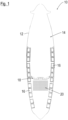
- FIG. 1 the fuselage of an aircraft 10 according to the invention is shown and denoted with reference numeral 12.
- the aircraft 10 is shown without its wings, yet comprises a cabin 14 in its front part as well as a number of battery modules 16 positioned adjacent to the inner walls of the fuselage 12 along some of its longitudinal extension.
- Said battery modules 16 each consist of a housing in which a plurality of individual battery cells are housed and interconnected. Behind a bulkhead 18 separating the cabin 14 from the rear part of the fuselage 12, some components of a thermal management system 20 according to the invention are positioned, such as the compressor and the condenser unit as will be discussed below.
- Said thermal management system 20 is adapted to cool both the cabin 14 and the battery modules 16, wherein all of the battery modules 16 in total form the battery assembly of the aircraft 10.
- Fig. 2 schematically shows a first embodiment of a thermal management system according to the invention, which may serve as the thermal management system 20 in the aircraft 10 of Fig. 1 .
- Said thermal management system 100 comprises a cooling circuit 102 configured to circulate a two-phase cooling fluid, such as for example R134a or R1233zd, and to which a compressor 104 for compressing the cooling fluid in its vapor phase and a condenser unit 106 for condensing the compressed cooling fluid and outputting the cooling fluid in its liquid phase are provided.
- a cooling circuit 102 configured to circulate a two-phase cooling fluid, such as for example R134a or R1233zd, and to which a compressor 104 for compressing the cooling fluid in its vapor phase and a condenser unit 106 for condensing the compressed cooling fluid and outputting the cooling fluid in its liquid phase are provided.
- each of the cabin cooling unit 108 and the battery cooling unit 110 in turn comprises a controllable expansion valve 108a, 110a and an evaporator 108b, 110b.
- the controllable expansion valves 108a, 110a as well as the compressor 104 are controlled by a control unit, which is omitted in Fig. 2 as well as Figs. 3A-3C described below.
- a second cooling fluid which may be different from the cooling fluid circulating in the cooling circuit 102, circulates and is for this purpose driven by a pump unit 114, which ensures that each of the battery modules 16 is adequately supplied with the second cooling fluid.
- the three variations of a second embodiment shown in Figs. 3A-3C rely on evaporating the cooling fluid directly inside the individual battery modules 16.
- the three individual variations are denoted with the reference numerals 200, 300 and 400 and each comprise cooling circuits 202, 302, 402, compressors 204, 304, 404 as well as condensers 206, 306, 406 similar to the embodiment shown in Fig. 2 .
- the respective cabin cooling units 208, 308, 408 also correspond to the cabin cooling unit 108 shown in the embodiment of Fig. 2 , each comprising controllable expansion valves 208a, 308a, 408a as well as evaporators 208b, 308b, 408b.
- a single controllable expansion valve 210a is provided, which is associated with all of the battery modules 16.
- This design requires both an additional liquid vapor separator 212 upstream of the compressor 204 and an according control strategy for the cabin cooling unit 208, such that the overheating of the cooling fluid circulating through the evaporator 208b of the cabin cooling unit is controlled in such a manner that in the liquid-vapor separator 212 the liquid cooling unit evaporates to a sufficient degree in order to be able to supply it to the compressor 204 for further circulation in the cooling circuit 202.
- each of the battery modules 16 is individually provided with a separate controllable expansion valve 310a, such that the flow of cooling fluid to each of the battery modules 16 may be separately controlled. While this particular design allows for a highly granular heat dissipation from each of the battery modules 16, in particular according to temperature data provided for each battery module 16 individually by suitable temperature sensors which are not shown in Fig. 3B , care has to be taken that in each battery module 16 the cooling fluid is fully evaporated.
- Fig. 3C shows a third variation, in which in the battery cooling unit 410 again a single expansion valve 410a is provided.
- an additional liquid-vapor separator 412 as well as a pump unit 414 is provided, such that the liquid-vapor separator 412 serves as a reservoir for cooling fluid which will again be evaporated directly inside the individual battery modules 16, while the expansion valve 410 is controlled in such a manner that the liquid level inside the liquid-vapor separator 412 is kept substantially constant during operation.
Landscapes
- Engineering & Computer Science (AREA)
- Chemical & Material Sciences (AREA)
- Aviation & Aerospace Engineering (AREA)
- General Chemical & Material Sciences (AREA)
- Manufacturing & Machinery (AREA)
- Chemical Kinetics & Catalysis (AREA)
- Electrochemistry (AREA)
- Pulmonology (AREA)
- General Health & Medical Sciences (AREA)
- Health & Medical Sciences (AREA)
- Combustion & Propulsion (AREA)
- Mechanical Engineering (AREA)
- Secondary Cells (AREA)
Abstract
Description
- The present invention relates to a thermal management system for an aircraft with a cabin and a battery assembly comprising a plurality of battery modules as well as to an aircraft equipped with such a thermal management system.
- In particular in electrically propelled aircraft or aircraft which supply other major loads with energy from battery cells, a high-performance thermal management system for the according battery assembly is required in order to be able to handle the heat produced by battery assemblies with high capacity and high peak power output during their operation. Furthermore, cabins in aircraft also require a thermal management system since, especially in designs in which a large percentage of the cabin is covered by glass surfaces, heat will accumulate in the cabin to an extent which would be uncomfortable for passengers and pilots.
- In general, such thermal management systems need to be able to fulfill the objectives of providing large cooling capacities through small surfaces in order to enable the extraction of high heat fluxes and to provide uniform cooling to all battery cells provided in the battery modules. Furthermore, finding a lightweight and energy-efficient design for the thermal management system is also of utmost importance for any aircraft in order to be able to achieve efficient operation.
- However, especially for high capacity and high power battery systems that are locally distributed within such an aircraft, uniform cooling at high cooling capacities can hardly be achieved with standard battery thermal management systems. Such standard battery thermal management systems cycle a cooling liquid, which absorbs sensible heat and changes its temperature. Such cooling systems, however, require large components with corresponding heavy weight in order to be able to provide the required cooling performance. Furthermore, the temperature change of the cooling liquid complicates the uniform cooling of all battery cells in the battery modules.
- It is therefore the object of the present invention to provide a high-performance thermal management system for an aircraft with low weight and uniform cooling capabilities for all battery cells in the battery modules of the aircraft.
- For this purpose, the system according to the present invention comprises a cooling circuit configured to circulate a two-phase cooling fluid, the cooling circuit in turn comprising a compressor for compressing the cooling fluid in its vapor phase, a condenser unit for condensing the compressed cooling fluid and outputting the cooling fluid in its liquid phase, a cabin cooling unit with a controllable expansion valve and configured to cool the cabin, and a battery cooling unit with at least one controllable expansion valve and configured to cool the plurality of battery modules, as well as a control unit for controlling operation of the compressor and the controllable expansion valves, wherein each of the cabin cooling unit and the battery cooling unit are configured to evaporate the liquid cooling fluid and to output the cooling fluid in its vapor phase.
- Thus, by evaporating a two-phase fluid in both a cabin cooling unit and a battery cooling unit, an improved cooling performance can be achieved, since instead of a single-phase fluid drawing on sensible heat, the invention suggests using a two-phase fluid drawing on latent heat, which per volume flow or mass flow is larger than sensible heat. Consequently, the cooling fluid volume flow or mass flow can accordingly be reduced, which in turn allows a reduction of the size of the cooling circuit and the amount of cooling fluid to be carried. This downsizing of relevant components leads to substantial mass savings in the system according to the invention.
- Furthermore, during the liquid-vapor phase change of the cooling fluid, its temperature does not change. Consequently, the battery assembly is subjected to a uniform cooling temperature, which in turn results in a very uniform cooling performance. It shall at this point be mentioned that the battery modules each typically consist of a plurality of separate battery cells, which are housed in a battery module housing and are interconnected with one another according to a certain scheme within the module housing.
- In order to be able to ensure that the compressor unit does not draw in the cooling fluid in its liquid phase, the cooling circuit in the system according to the present invention may further comprise at least one liquid-vapor separator unit, which is positioned upstream of the compressor in the circulation direction of the cooling fluid in the cooling circuit.
- Also, and in order to be able to suitably control the operation of the compressor and the controllable expansion valves by means of the control unit, the system according to the invention comprises several temperature sensors. In order to suitably control the complete evaporation of the cooling fluid before it enters the compressor, a temperature sensor is positioned downstream of at least one expansion valve in the cooling circuit. One additional temperature sensor per expansion valve is furthermore positioned downstream of the corresponding evaporator unit. If evaporator units which are arranged in parallel share a single expansion valve, the corresponding single temperature sensor is placed downstream of the unification point of the parallel evaporation branches.
- The system according to the invention may further comprise at least one temperature sensor unit configured to measure a temperature of the cabin or the battery assembly, wherein preferably each battery module is provided with at least one separate temperature sensor unit. For this purpose, the control unit of the thermal management system may not only be coupled to the respective at least one sensor unit in order to receive its output and control the compressor as well as the controllable expansion valves accordingly, but may furthermore also be coupled to additional data collecting and data processing components of the aircraft. In particular, the control unit of the thermal management system may be coupled to a central computing unit of the aircraft or may even be integrated therein.
- While it is in principle possible to divert the heat removed from the cabin as well as the battery assembly by means of the condenser unit to the outside of the aircraft, in other embodiments the system according to the present invention may further comprise a heat exchanger to recover the heat produced in the condenser unit for providing heat to other systems of the aircraft, such as a de-icing system for wing tips and/or engines.
- In one possible embodiment of the system according to the present invention, each of the cabin cooling unit and the battery cooling unit may comprise an evaporator in which the liquid cooling fluid is evaporated, wherein the evaporator of the battery cooling unit is coupled to a secondary cooling circuit to form a heat exchanger, wherein the secondary cooling circuit provides secondary cooling fluid to the battery modules of the battery assembly for cooling them. While this particular embodiment requires a dedicated evaporator for the battery cooling unit as well as an additional pump unit in the secondary cooling circuit, it offers the advantages that due to the provision of the secondary cooling circuit, a decoupling between the battery modules and the evaporator unit is achieved and that the cooling circuit and the secondary cooling circuit may be provided with different cooling fluids, which in some embodiments may yield beneficial effects concerning the reliability and efficiency of the system. The secondary cooling circuit of the battery cooling unit can be operated in single-phase or two-phase heat exchange. In two-phase operation, partial evaporation of the cooling fluid in the battery modules can be tolerated in the secondary cooling circuit.
- In another embodiment, the battery cooling unit may be integrated with the battery assembly in such a manner that the evaporation of the liquid cooling fluid takes place inside the housings of the individual battery modules. Thus, in this particular embodiment, the housings of the individual battery modules themselves serve as evaporators and the latent heat for evaporating the cooling fluid is directly provided by the battery cells themselves. Providing such a uniform cooling to each of the battery cells with a fixed evaporation temperature of the cooling fluid may further contribute to reduced aging of the battery cells during operation and thus an increase in the cycle life of the battery cells, which over the lifespan of the aircraft may lead to a substantial reduction of costs.
- Different variations of the embodiment with direct evaporation of the cooling fluid inside the battery modules are conceivable, for example the battery cooling unit may be provided with a single controllable expansion valve. While this particular design of the system according to the invention eliminates the need for a dedicated evaporator in the battery cooling unit, it nevertheless has to be made sure that only cooling fluid in its vapor phase will reach the compressor.
- For this purpose, downstream of the battery modules of the battery cooling unit, a liquid-vapor separator may be provided, wherein the liquid-vapor separator may be arranged such that cooling fluid in its vapor phase is directed to the compressor, while cooling fluid in its liquid phase is directed to the battery assembly by means of a pump unit. While in this particular design of the system according to the invention providing only a single controllable expansion valve for the entire battery assembly will lead to a reduction of weight and costs of the system, the overheating of the cooling fluid being discharged from the cabin cooling unit has to be controlled to such an amount that in the liquid-vapor separator liquid cooling fluid will evaporate in order to be supplied to the compressor.
- In another variation of the above-discussed embodiment, the battery cooling unit may be provided with a plurality of controllable expansion valves, wherein each of the battery modules is provided with a separate controllable expansion valve. This particular variation has the advantage that differences in heat produced between the individual battery modules can individually be levelled by accordingly controlled cooling fluid mass flows for the individual battery modules. This, on the other hand, leads to the necessity of providing thermally controlled expansion valves for each battery module, which are able to control the cooling fluid flow in such a manner that a complete evaporation of the cooling fluid provided to each battery module will occur.
- In another possible embodiment of the present invention, the battery cooling unit may again be provided with a single expansion valve, wherein in said battery cooling unit, an additional liquid-vapor separator as well as a pump unit may be provided, such that the liquid-vapor separator may serve as a reservoir for cooling fluid which will again be evaporated directly inside the individual battery modules, while the expansion valve is controlled in such a manner that the liquid level inside the liquid-vapor separator is kept substantially constant during operation.
- Furthermore, the present invention relates to an aircraft, comprising a fuselage with a cabin, a battery assembly comprising a plurality of battery modules and a thermal management system according to the present invention. Said aircraft may in particular be an electrically propelled aircraft, for example with vertical takeoff and landing capabilities, since in such aircraft designs, high electrical power is drawn from the battery assembly especially during takeoff, hovering and landing operations.
- The aircraft according to the invention may further comprise at least one additional component to be cooled by the thermal management system, in particular at least one electrical propulsion engine. Said cooling can accordingly be performed with either direct evaporation of the cooling fluid in the vicinity of the component to be cooled or by means of a heat exchanger and a secondary cooling circuit as discussed above.
- In a possible design of the aircraft according to the invention, at least some of the battery modules of the battery assembly may be positioned adjacent to the inner walls of the fuselage and the thermal management system may be positioned at the centerline of the aircraft in between the battery modules. Thus, the system can be built relatively compact and extensive piping can be avoided, which leads to a reduced weight and an efficiency increase of the system.
- Additional features and advantages of the present invention will become even clearer from the following description of embodiments thereof when taken together with the accompanying drawings. These show in particular:
- Fig. 1
- a schematic plan view of the fuselage of an aircraft according to the invention;
- Fig. 2
- a first embodiment of a thermal management system according to the invention in a schematic view; and
- Figs. 3A-3C
- three variations of a second embodiment of a thermal management system according to the invention.
- In
Fig. 1 , the fuselage of anaircraft 10 according to the invention is shown and denoted withreference numeral 12. Herein, theaircraft 10 is shown without its wings, yet comprises acabin 14 in its front part as well as a number ofbattery modules 16 positioned adjacent to the inner walls of thefuselage 12 along some of its longitudinal extension. - Said
battery modules 16 each consist of a housing in which a plurality of individual battery cells are housed and interconnected. Behind abulkhead 18 separating thecabin 14 from the rear part of thefuselage 12, some components of athermal management system 20 according to the invention are positioned, such as the compressor and the condenser unit as will be discussed below. - Said
thermal management system 20 is adapted to cool both thecabin 14 and thebattery modules 16, wherein all of thebattery modules 16 in total form the battery assembly of theaircraft 10. -
Fig. 2 schematically shows a first embodiment of a thermal management system according to the invention, which may serve as thethermal management system 20 in theaircraft 10 ofFig. 1 . - Said
thermal management system 100 comprises acooling circuit 102 configured to circulate a two-phase cooling fluid, such as for example R134a or R1233zd, and to which acompressor 104 for compressing the cooling fluid in its vapor phase and acondenser unit 106 for condensing the compressed cooling fluid and outputting the cooling fluid in its liquid phase are provided. - Said cooling fluid in its liquid phase is then supplied to a
cabin cooling unit 108 as well as abattery cooling unit 110, which are arranged in parallel in thecooling circuit 102. In the embodiment ofFig. 1 , each of thecabin cooling unit 108 and thebattery cooling unit 110 in turn comprises acontrollable expansion valve evaporator controllable expansion valves compressor 104 are controlled by a control unit, which is omitted inFig. 2 as well asFigs. 3A-3C described below. - While the
cabin evaporator 108b in the embodiment shown inFig. 2 directly cools thecabin 12 of theaircraft 10, the evaporator 110b of thebattery cooling unit 110 is coupled to asecondary cooling circuit 112 to form a heat exchanger. In saidsecondary cooling circuit 112, a second cooling fluid, which may be different from the cooling fluid circulating in thecooling circuit 102, circulates and is for this purpose driven by apump unit 114, which ensures that each of thebattery modules 16 is adequately supplied with the second cooling fluid. - While thus the embodiment shown in
Fig. 2 relies on the evaporator 110b of the battery cooling unit to form part of a heat exchanger as well as on thesecondary cooling circuit 112, the three variations of a second embodiment shown inFigs. 3A-3C rely on evaporating the cooling fluid directly inside theindividual battery modules 16. Therein, the three individual variations are denoted with thereference numerals circuits compressors condensers Fig. 2 . The respectivecabin cooling units cabin cooling unit 108 shown in the embodiment ofFig. 2 , each comprisingcontrollable expansion valves evaporators - Thus, the differences between the three variations shown in
Figs. 3A-3C merely relate to the design of thebattery cooling units Fig. 3A , a singlecontrollable expansion valve 210a is provided, which is associated with all of thebattery modules 16. This design requires both an additional liquid vapor separator 212 upstream of thecompressor 204 and an according control strategy for thecabin cooling unit 208, such that the overheating of the cooling fluid circulating through the evaporator 208b of the cabin cooling unit is controlled in such a manner that in the liquid-vapor separator 212 the liquid cooling unit evaporates to a sufficient degree in order to be able to supply it to thecompressor 204 for further circulation in thecooling circuit 202. - In contrast, in the variation shown in
Fig. 3B , each of thebattery modules 16 is individually provided with a separatecontrollable expansion valve 310a, such that the flow of cooling fluid to each of thebattery modules 16 may be separately controlled. While this particular design allows for a highly granular heat dissipation from each of thebattery modules 16, in particular according to temperature data provided for eachbattery module 16 individually by suitable temperature sensors which are not shown inFig. 3B , care has to be taken that in eachbattery module 16 the cooling fluid is fully evaporated. - Lastly,
Fig. 3C shows a third variation, in which in thebattery cooling unit 410 again asingle expansion valve 410a is provided. In saidbattery cooling unit 410, an additional liquid-vapor separator 412 as well as apump unit 414 is provided, such that the liquid-vapor separator 412 serves as a reservoir for cooling fluid which will again be evaporated directly inside theindividual battery modules 16, while theexpansion valve 410 is controlled in such a manner that the liquid level inside the liquid-vapor separator 412 is kept substantially constant during operation.
Claims (14)
- Thermal management system (100; 200; 300; 400) for an aircraft (10) with a cabin (14) and a battery assembly comprising a plurality of battery modules (16), the system (100; 200; 300; 400) comprising:- a cooling circuit (102; 202; 302; 402) configured to circulate a two-phase cooling fluid, the cooling circuit comprising:∘ a compressor (104; 204; 304; 404) for compressing the cooling fluid in its vapor phase;∘ a condenser unit (106; 206; 306; 406) for condensing the compressed cooling fluid and outputting the cooling fluid in its liquid phase;∘ a cabin cooling unit (108; 208; 308; 408) with a controllable expansion valve (108a; 208a; 308a; 408a) and configured to cool the cabin (14); and∘ a battery cooling unit (110; 210; 310; 410) with at least one controllable expansion valve (110a; 210a; 310a; 410a) and configured to cool the plurality of battery modules (16);- a plurality of temperature sensors;- a control unit for controlling operation of the compressor (104; 204; 304; 404) and the controllable expansion valves (108a, 110a; 208a, 210a; 308a, 310a; 408a, 410a);wherein each of the cabin cooling unit (108; 208; 308; 408) and the battery cooling unit (110; 210; 310; 410) are configured to evaporate the liquid cooling fluid.
- Thermal management system (200; 400) according to claim 1,
wherein the cooling circuit (202; 402) further comprises at least one liquid-vapor separator unit (212; 412) which is positioned upstream of the compressor (204; 404) in the circulation direction of the cooling fluid. - Thermal management system according to any of the preceding claims, wherein the plurality of temperature sensors comprises at least one temperature sensor unit configured to measure a temperature of the cabin (14) or the battery assembly, wherein preferably each battery module (16) is provided with a separate temperature sensor unit.
- Thermal management system according to any of the preceding claims,
further comprising a heat exchanger to recover the heat produced in the condenser unit. - Thermal management system (100) according to any of the preceding claims,wherein each of the cabin cooling unit (108) and the battery cooling unit (110) comprises an evaporator (108b, 110b) in which the liquid cooling fluid is evaporated,wherein the evaporator (110b) of the battery cooling unit (110) is coupled to a secondary cooling circuit (112) to form a heat exchanger,wherein the secondary cooling circuit (112) provides secondary cooling fluid to the battery modules (16) of the battery assembly for cooling them.
- Thermal management system (100) according to claim 5,
wherein the secondary cooling circuit (112) is provided with a pump unit (114) for circulating cooling fluid therein. - Thermal management (100) system according to any of claims 5 and 6,
wherein cooling circuit (102) and the secondary cooling circuit (112) are provided with different cooling fluids. - Thermal management system (200; 300; 400) according to any of claims 1 to 4,
wherein the battery cooling unit (210; 310; 410) is integrated with the battery assembly in such a manner that the evaporation of the liquid cooling fluid takes place inside the battery modules (16). - Thermal management system (200) according to claim 8,
wherein the battery cooling unit (210) is provided with a single controllable expansion valve (210a). - Thermal management system (400) according to claim 9,wherein downstream of the single controllable expansion valve (410a) of the battery cooling unit (410) a liquid-vapor separator unit (412) is provided,wherein the liquid-vapor separator unit (412) is arranged such that cooling fluid in vapor phase is directed to the compressor (404) while cooling fluid in liquid phase is directed to the battery assembly by means of a pump unit (414).
- Thermal management system (300) according to claim 8,
wherein the battery cooling unit (310) is provided with a plurality of controllable expansion valves (310a), wherein each of the battery modules (16) is provided with a separate controllable expansion valve (310a). - Aircraft (10), comprising a fuselage (12) with a cabin (14), a battery assembly comprising a plurality of battery modules (16) and a thermal management system (20) according to any of the preceding claims.
- Aircraft according to claim 12,
wherein the aircraft further comprises at least one additional component to be cooled by the thermal management system (20), in particular at least one electrical propulsion engine. - Aircraft (10) according to any of claims 12 and 13,
wherein at least some of the battery modules (16) of the battery assembly are positioned adjacent to the inner walls of the fuselage (12) and the thermal management system (20) is positioned at the centerline of the aircraft in between the battery modules.
Priority Applications (1)
| Application Number | Priority Date | Filing Date | Title |
|---|---|---|---|
| EP21199174.0A EP4155208A1 (en) | 2021-09-27 | 2021-09-27 | Thermal management system for an aircraft |
Applications Claiming Priority (1)
| Application Number | Priority Date | Filing Date | Title |
|---|---|---|---|
| EP21199174.0A EP4155208A1 (en) | 2021-09-27 | 2021-09-27 | Thermal management system for an aircraft |
Publications (1)
| Publication Number | Publication Date |
|---|---|
| EP4155208A1 true EP4155208A1 (en) | 2023-03-29 |
Family
ID=77998752
Family Applications (1)
| Application Number | Title | Priority Date | Filing Date |
|---|---|---|---|
| EP21199174.0A Pending EP4155208A1 (en) | 2021-09-27 | 2021-09-27 | Thermal management system for an aircraft |
Country Status (1)
| Country | Link |
|---|---|
| EP (1) | EP4155208A1 (en) |
Cited By (3)
| Publication number | Priority date | Publication date | Assignee | Title |
|---|---|---|---|---|
| CN117622492A (en) * | 2024-01-25 | 2024-03-01 | 四川沃飞长空科技发展有限公司 | Aircraft cabin temperature adjustment system and control method |
| US12330524B2 (en) | 2023-10-16 | 2025-06-17 | Archer Aviation, Inc. | Systems and methods for high voltage battery charging and vertiport operations |
| DE102024116403A1 (en) | 2024-06-12 | 2025-12-18 | Dr. Ing. H.C. F. Porsche Aktiengesellschaft | Device and method for cooling a component of a vertical take-off and landing aircraft, the device comprising a vertical take-off and landing aircraft |
Citations (8)
| Publication number | Priority date | Publication date | Assignee | Title |
|---|---|---|---|---|
| US20090249802A1 (en) * | 2008-04-04 | 2009-10-08 | Gm Global Technology Operations, Inc. | Vehicle HVAC and Battery Thermal Management |
| CN108688803A (en) * | 2018-07-26 | 2018-10-23 | 杨福鼎 | It is a kind of can VTOL aircraft |
| DE102018101514A1 (en) * | 2018-01-24 | 2019-07-25 | Hanon Systems | Motor vehicle refrigeration system with several evaporators of different refrigerating capacity |
| US10384511B2 (en) * | 2017-01-27 | 2019-08-20 | Ford Global Technologies, Llc | Method to control battery cooling using the battery coolant pump in electrified vehicles |
| US20200343611A1 (en) * | 2018-01-25 | 2020-10-29 | Denso Corporation | Refrigeration cycle device for cooling battery |
| US20200361279A1 (en) * | 2019-05-13 | 2020-11-19 | Aikar Technology Inc. | Vehicle thermal method and system |
| EP3800724A1 (en) * | 2019-10-04 | 2021-04-07 | Siemens Aktiengesellschaft | Battery cooling system for an aircraft |
| US20210213798A1 (en) * | 2020-01-15 | 2021-07-15 | Ford Global Technologies, Llc | Thermal management for electrified vehicle |
-
2021
- 2021-09-27 EP EP21199174.0A patent/EP4155208A1/en active Pending
Patent Citations (8)
| Publication number | Priority date | Publication date | Assignee | Title |
|---|---|---|---|---|
| US20090249802A1 (en) * | 2008-04-04 | 2009-10-08 | Gm Global Technology Operations, Inc. | Vehicle HVAC and Battery Thermal Management |
| US10384511B2 (en) * | 2017-01-27 | 2019-08-20 | Ford Global Technologies, Llc | Method to control battery cooling using the battery coolant pump in electrified vehicles |
| DE102018101514A1 (en) * | 2018-01-24 | 2019-07-25 | Hanon Systems | Motor vehicle refrigeration system with several evaporators of different refrigerating capacity |
| US20200343611A1 (en) * | 2018-01-25 | 2020-10-29 | Denso Corporation | Refrigeration cycle device for cooling battery |
| CN108688803A (en) * | 2018-07-26 | 2018-10-23 | 杨福鼎 | It is a kind of can VTOL aircraft |
| US20200361279A1 (en) * | 2019-05-13 | 2020-11-19 | Aikar Technology Inc. | Vehicle thermal method and system |
| EP3800724A1 (en) * | 2019-10-04 | 2021-04-07 | Siemens Aktiengesellschaft | Battery cooling system for an aircraft |
| US20210213798A1 (en) * | 2020-01-15 | 2021-07-15 | Ford Global Technologies, Llc | Thermal management for electrified vehicle |
Cited By (4)
| Publication number | Priority date | Publication date | Assignee | Title |
|---|---|---|---|---|
| US12330524B2 (en) | 2023-10-16 | 2025-06-17 | Archer Aviation, Inc. | Systems and methods for high voltage battery charging and vertiport operations |
| CN117622492A (en) * | 2024-01-25 | 2024-03-01 | 四川沃飞长空科技发展有限公司 | Aircraft cabin temperature adjustment system and control method |
| CN117622492B (en) * | 2024-01-25 | 2024-05-17 | 四川沃飞长空科技发展有限公司 | Temperature regulating system in aircraft cabin and control method |
| DE102024116403A1 (en) | 2024-06-12 | 2025-12-18 | Dr. Ing. H.C. F. Porsche Aktiengesellschaft | Device and method for cooling a component of a vertical take-off and landing aircraft, the device comprising a vertical take-off and landing aircraft |
Similar Documents
| Publication | Publication Date | Title |
|---|---|---|
| US12319127B2 (en) | Heat pump arrangement with indirect battery heating for battery-operated motor vehicles and method of operating a heat pump arrangement | |
| CN110549817B (en) | Heat flow management device and method for operating a heat flow management device | |
| EP3017256B1 (en) | Aircraft galley air chiller system | |
| KR102294593B1 (en) | Thermal system of a motor vehicle and method for operating the thermal system | |
| CA2925337C (en) | Aircraft air chiller with reduced profile | |
| US10800535B2 (en) | Integrated environmental control systems and methods for controlling environmental temperature of an enclosed space | |
| US7954331B2 (en) | Thermally-balanced solid state cooling | |
| CN115042977B (en) | Aircraft thermal management system for megawatt-class heat loads using low-temperature consumable heat sinks | |
| US20100084118A1 (en) | Cooling system for aircraft electric or electronic devices | |
| TR201612616A2 (en) | ||
| US9561856B2 (en) | Heat exchanger, cooling system and method for operating a heat exchanger and a cooling system | |
| US10364043B2 (en) | Passive aircraft cooling systems and methods | |
| US12240620B2 (en) | Thermal management system | |
| US7523622B2 (en) | Aircraft galley chiller system | |
| WO2003039953A1 (en) | Recirculating regenerative air cycle | |
| WO2012158297A2 (en) | Method and apparatus for aircraft galley cooling | |
| US12220965B2 (en) | Thermal management system with dual condensers | |
| US9272788B2 (en) | Aircraft cooling system and method for operating an aircraft cooling system | |
| US20230347708A1 (en) | Method of operating a cooling system | |
| US9698435B2 (en) | System and method for cooling an aircraft fuel cell system | |
| EP2650218B1 (en) | Aircraft thermal control system and method of operating an aircraft thermal control system | |
| EP1441947A1 (en) | Recirculating regenerative air cycle |
Legal Events
| Date | Code | Title | Description |
|---|---|---|---|
| PUAI | Public reference made under article 153(3) epc to a published international application that has entered the european phase |
Free format text: ORIGINAL CODE: 0009012 |
|
| STAA | Information on the status of an ep patent application or granted ep patent |
Free format text: STATUS: THE APPLICATION HAS BEEN PUBLISHED |
|
| AK | Designated contracting states |
Kind code of ref document: A1 Designated state(s): AL AT BE BG CH CY CZ DE DK EE ES FI FR GB GR HR HU IE IS IT LI LT LU LV MC MK MT NL NO PL PT RO RS SE SI SK SM TR |
|
| STAA | Information on the status of an ep patent application or granted ep patent |
Free format text: STATUS: REQUEST FOR EXAMINATION WAS MADE |
|
| 17P | Request for examination filed |
Effective date: 20230510 |
|
| RBV | Designated contracting states (corrected) |
Designated state(s): AL AT BE BG CH CY CZ DE DK EE ES FI FR GB GR HR HU IE IS IT LI LT LU LV MC MK MT NL NO PL PT RO RS SE SI SK SM TR |
|
| STAA | Information on the status of an ep patent application or granted ep patent |
Free format text: STATUS: EXAMINATION IS IN PROGRESS |
|
| 17Q | First examination report despatched |
Effective date: 20240301 |
|
| GRAP | Despatch of communication of intention to grant a patent |
Free format text: ORIGINAL CODE: EPIDOSNIGR1 |
|
| STAA | Information on the status of an ep patent application or granted ep patent |
Free format text: STATUS: GRANT OF PATENT IS INTENDED |
|
| RIC1 | Information provided on ipc code assigned before grant |
Ipc: B64D 27/357 20240101ALI20250115BHEP Ipc: H01M 10/663 20140101ALI20250115BHEP Ipc: H01M 10/48 20060101ALI20250115BHEP Ipc: H01M 10/6569 20140101ALI20250115BHEP Ipc: H01M 10/6568 20140101ALI20250115BHEP Ipc: H01M 10/625 20140101ALI20250115BHEP Ipc: H01M 10/613 20140101ALI20250115BHEP Ipc: B64D 33/08 20060101ALI20250115BHEP Ipc: B64D 27/34 20240101ALI20250115BHEP Ipc: B64D 13/08 20060101ALI20250115BHEP Ipc: B64D 13/06 20060101AFI20250115BHEP |
|
| INTG | Intention to grant announced |
Effective date: 20250129 |
|
| 19U | Interruption of proceedings before grant |
Effective date: 20250313 |
|
| 19W | Proceedings resumed before grant after interruption of proceedings |
Effective date: 20260401 |
|
| RAP1 | Party data changed (applicant data changed or rights of an application transferred) |
Owner name: ARCHER AVIATION INC. |
|
| GRAS | Grant fee paid |
Free format text: ORIGINAL CODE: EPIDOSNIGR3 |
|
| GRAA | (expected) grant |
Free format text: ORIGINAL CODE: 0009210 |
|
| STAA | Information on the status of an ep patent application or granted ep patent |
Free format text: STATUS: THE PATENT HAS BEEN GRANTED |