EP4155186A1 - Bicycle electric/electronic derailleur of the articulated parallelogram type - Google Patents
Bicycle electric/electronic derailleur of the articulated parallelogram type Download PDFInfo
- Publication number
- EP4155186A1 EP4155186A1 EP22197993.3A EP22197993A EP4155186A1 EP 4155186 A1 EP4155186 A1 EP 4155186A1 EP 22197993 A EP22197993 A EP 22197993A EP 4155186 A1 EP4155186 A1 EP 4155186A1
- Authority
- EP
- European Patent Office
- Prior art keywords
- derailleur
- component
- case
- hole
- axis
- Prior art date
- Legal status (The legal status is an assumption and is not a legal conclusion. Google has not performed a legal analysis and makes no representation as to the accuracy of the status listed.)
- Granted
Links
Images



Classifications
-
- B—PERFORMING OPERATIONS; TRANSPORTING
- B62—LAND VEHICLES FOR TRAVELLING OTHERWISE THAN ON RAILS
- B62M—RIDER PROPULSION OF WHEELED VEHICLES OR SLEDGES; POWERED PROPULSION OF SLEDGES OR SINGLE-TRACK CYCLES; TRANSMISSIONS SPECIALLY ADAPTED FOR SUCH VEHICLES
- B62M9/00—Transmissions characterised by use of an endless chain, belt, or the like
- B62M9/04—Transmissions characterised by use of an endless chain, belt, or the like of changeable ratio
- B62M9/06—Transmissions characterised by use of an endless chain, belt, or the like of changeable ratio using a single chain, belt, or the like
- B62M9/10—Transmissions characterised by use of an endless chain, belt, or the like of changeable ratio using a single chain, belt, or the like involving different-sized wheels, e.g. rear sprocket chain wheels selectively engaged by the chain, belt, or the like
- B62M9/12—Transmissions characterised by use of an endless chain, belt, or the like of changeable ratio using a single chain, belt, or the like involving different-sized wheels, e.g. rear sprocket chain wheels selectively engaged by the chain, belt, or the like the chain, belt, or the like being laterally shiftable, e.g. using a rear derailleur
- B62M9/121—Rear derailleurs
- B62M9/122—Rear derailleurs electrically or fluid actuated; Controls thereof
-
- B—PERFORMING OPERATIONS; TRANSPORTING
- B62—LAND VEHICLES FOR TRAVELLING OTHERWISE THAN ON RAILS
- B62M—RIDER PROPULSION OF WHEELED VEHICLES OR SLEDGES; POWERED PROPULSION OF SLEDGES OR SINGLE-TRACK CYCLES; TRANSMISSIONS SPECIALLY ADAPTED FOR SUCH VEHICLES
- B62M9/00—Transmissions characterised by use of an endless chain, belt, or the like
- B62M9/04—Transmissions characterised by use of an endless chain, belt, or the like of changeable ratio
- B62M9/06—Transmissions characterised by use of an endless chain, belt, or the like of changeable ratio using a single chain, belt, or the like
- B62M9/10—Transmissions characterised by use of an endless chain, belt, or the like of changeable ratio using a single chain, belt, or the like involving different-sized wheels, e.g. rear sprocket chain wheels selectively engaged by the chain, belt, or the like
- B62M9/12—Transmissions characterised by use of an endless chain, belt, or the like of changeable ratio using a single chain, belt, or the like involving different-sized wheels, e.g. rear sprocket chain wheels selectively engaged by the chain, belt, or the like the chain, belt, or the like being laterally shiftable, e.g. using a rear derailleur
- B62M9/121—Rear derailleurs
- B62M9/124—Mechanisms for shifting laterally
- B62M9/1242—Mechanisms for shifting laterally characterised by the linkage mechanisms
-
- B—PERFORMING OPERATIONS; TRANSPORTING
- B62—LAND VEHICLES FOR TRAVELLING OTHERWISE THAN ON RAILS
- B62M—RIDER PROPULSION OF WHEELED VEHICLES OR SLEDGES; POWERED PROPULSION OF SLEDGES OR SINGLE-TRACK CYCLES; TRANSMISSIONS SPECIALLY ADAPTED FOR SUCH VEHICLES
- B62M9/00—Transmissions characterised by use of an endless chain, belt, or the like
- B62M9/04—Transmissions characterised by use of an endless chain, belt, or the like of changeable ratio
- B62M9/06—Transmissions characterised by use of an endless chain, belt, or the like of changeable ratio using a single chain, belt, or the like
- B62M9/10—Transmissions characterised by use of an endless chain, belt, or the like of changeable ratio using a single chain, belt, or the like involving different-sized wheels, e.g. rear sprocket chain wheels selectively engaged by the chain, belt, or the like
- B62M9/12—Transmissions characterised by use of an endless chain, belt, or the like of changeable ratio using a single chain, belt, or the like involving different-sized wheels, e.g. rear sprocket chain wheels selectively engaged by the chain, belt, or the like the chain, belt, or the like being laterally shiftable, e.g. using a rear derailleur
- B62M9/121—Rear derailleurs
- B62M9/124—Mechanisms for shifting laterally
- B62M9/1244—Mechanisms for shifting laterally limiting or positioning the movement
- B62M9/1246—Mechanisms for shifting laterally limiting or positioning the movement using cams or plates
Definitions
- the present invention relates to a bicycle electric/electronic derailleur of the articulated parallelogram type.
- electric/electronic is used to indicate an electric device that may also include electronic components and/or a data processing system.
- a motion transmission system in a bicycle typically comprises a closed-loop chain extending between toothed wheels associated with the bottom bracket spindle and with the hub of the rear wheel, respectively.
- a closed-loop chain extending between toothed wheels associated with the bottom bracket spindle and with the hub of the rear wheel, respectively.
- chain is replaced by a toothed belt, but for the sake of brevity hereinafter and in the attached claims, term “chain” will be used to refer to both cases of motion transmission member between the two toothed wheels, in particular in the expression "chain guide”.
- chain guide is used to indicate the component which, overall, is moved with respect to the support body and to the connecting arms; in the case of a rear derailleur it may include a first member articulated in the articulated parallelogram, sometimes called “bottom body”, and a second member movable therewith, sometimes called “rocker arm”, while in the case of a front derailleur it typically comprises a single member, sometimes called "cage”.
- a bicycle derailleur of the articulated parallelogram type comprises a plurality of mutually movable components, comprising a support body configured to be attached to a bicycle frame, a chain guide, and a pair of connecting arms for connection between the support body and the chain guide at respective articulation axes.
- geared motor a motor not coupled with any speed reducer is meant to be encom passed.
- the output shaft of the geared motor may extend along an articulation axis in order to directly control the angular position of one of the mutually movable components, for example of one of the connecting arms, or it may extend along the diagonal of the parallelogram.
- gearshift For controlling the geared motor, electric/electronic signals issued by the manual control devices and/or processed by a data processing system, on the basis of detected quantities relating to the status of the cyclist and/or of the bicycle (deraille included) and/or of the route, are used, so that the gearshift may generally operate in manual mode (which on the other hand is the only one available in the case of a mechanical gearshift), in totally automatic mode and/or in semiautomatic mode.
- EP 3 266 694 A1 and corresponding US 2018/0001960 A1 disclose a bicycle electric derailleur comprising a support body that is configured to be attached to a frame of the bicycle, a chain guide connected to the support body through a linkage, an electric motor that drives the linkage to displace the chain guide among toothed wheels of a motion transmission system, wherein the linkage includes two connecting rods, the opposite ends of each of which are articulated to the support body and to the chain guide, to form an articulated parallelogram, wherein an output shaft of the electric motor or of the motor gear coincides with an articulation pivot of the articulated parallelogram linkage, wherein a pivot extending from one of the connecting rods engages in a hole formed at one end of the output shaft, and a second end of the output shaft of the electric motor or of the motor gear engages in a hole formed in said one of the connecting arms.
- the geared motor is supported by a framework that has two holes at the two ends of the output shaft of the motor gear, which framework is housed within an inner chamber defined by casing portions suitably constrained to each other, for example by thermowelding, ultrasound welding, sealing, gluing, etcetera.
- the configuration of that document requires a geared motor having an output shaft extended along the entire length necessary to define the articulation pivot, and that is hollow at the first end, what entails size and weight of the geared motor that may not be desirable in certain derailleurs - in particular, but not limited to, in the field of racing bicycles.
- the casing has a wide opening extending from one end of the output shaft of the geared motor to the other one in order to allow the rotation of one of the connecting arms, what allows entry of dirt, water and other liquids in the inner chamber, which may impair electric/electronic devices housed in the casing.
- the technical problem at the basis of the invention is to provide an electric/electronic derailleur of the articulated parallelogram type provided with at least one chamber that is or may be adequately and conveniently hermetically closed, so as to be well suited to contain one or more electric/electronic devices in the conditions of dirt and humidity to which the derailleur is subject.
- a secondary aim is to allow the derailleur to have contained weight and dimensions.
- the invention relates to a bicycle electric/electronic derailleur comprising:
- proximal and distal refer to the mounted condition of the derailleur on the bicycle.
- proximal is used to indicate closer to the frame and adjective “distal” is used to indicate farther from the frame.
- the first blind hole of the case may be provided with a blind bushing.
- the blind bushing may be overprinted in the first component.
- the pivot may be formed in a member comprising a screwing tool engagement head and a shank extending from the head, a portion of the shank contiguous to the head being provided with an external threading and the remaining portion of the shank being without threading, wherein the portion provided with external threading is screwed into an internally threaded through hole of the second component, the portion without threading protruding from the through hole forming said pivot.
- the internally threaded through hole may be made in an insert of the second component.
- the insert may be co-moulded in the second component.
- Said case may comprise a second blind hole coaxial with said first crossed axis and open outwards on one opposite side of said case with respect to the first blind hole, the second component comprising a second pivot pivotable in the second blind hole.
- said case may further comprise a through hole coaxial with said first crossed axis, the through hole being on the opposed side of said case with respect to the first blind hole, an output shaft of the geared motor extending through the through hole and through a hole of the second component, a hermetic seal gasket being provided for between the through hole and the output shaft.
- the pivotal coupling between the first and the second components may be made there through other means, for example a through hole extended in a case region not crossing the chamber wherein a pivot of the second component is pivotable, or a pivot of the first component pivotable in a hole of the second component.
- said case may comprise one or two additional blind hole(s), coaxial with the second crossed axis, a third component of the mutually movable components articulated to the first component at said second crossed axis comprising one or respectively two pivot(s) pivotable in said one or two additional blind hole(s).
- first component may be made also in one or more other components, so as to have plural hermetically closed chambers at disposal, with the structural restriction that each of the articulation axes is shared by two components.
- each of the second and the third components may have whatever conformation along the articulation axis that it shares with the fourth component, but along the other articulation axes they will in the first place have to feature the member matching that featured by the "first component".
- Said one or more electric/electronic devices may comprise an electric power supply unit, preferably of the secondary cell battery type, and/or one or more components controlling the geared motor and/or the electric power supply unit, if present.
- the first component may be the support body.
- the derailleur is, for example, a rear derailleur.
- the derailleur may also include a data processing system, controlling the geared motor and any other electric/electronic components of the derailleur.
- the data processing system may comprise electric components and/or discrete electronic components and/or a micro-controller, that may also integrate memory means.
- the data processing system may be borne for example on at least one printed circuit board or PCB.
- the derailleur may therefore be electronic.
- FIG. 1 a bicycle electric/electronic derailleur 1, of the articulated parallelogram type, is shown.
- the derailleur 1 comprises a support body 2 configured to be attached to a bicycle frame, a chain guide 3, and a pair of connecting arms 4, 5 between the support body 2 and the chain guide 3, forming a plurality of mutually movable components.
- the pair of connecting arms comprises a proximal connecting arm 4 and a distal connecting arm 5.
- the support body 4 may be attached to the frame through a connection device so-called "articulated joint" 15.
- the mutually movable components 2, 3, 4, 5 may for example be made of steel, a light alloy, a techno-polymer, a composite material and similar.
- the connecting arms 4, 5 are connected to the support body 2 and to the chain guide 3 at respective geometric articulation axes: a support body-proximal connecting arm articulation axis 6, a support body-distal connecting arm articulation axis 7, a chain guide-proximal connecting arm articulation axis 8, and a chain guide-distal connecting arm articulation axis 9.
- the electric derailleur 1 comprises a geared motor 10 ( FIG. 3 , 4 ).
- the geared motor 10 may be merely electric or electronic, when the derailleur also includes a data processing system controlling the geared motor 10 and any other electric/electronic components of the derailleur 1, for example comprising one or more components borne by one or more printed circuit boards or PCBs.
- the geared motor 10 may also comprise a motor not coupled with any speed reducer.
- the geared motor 10 controls the mutual motion of the mutually movable components 2, 3, 4, 5, in particular it determined the aperture and closure of the articulated parallelogram, and therefore a displacement of the chain guide 3 -with respect to the support body 2 and therefore to the bicycle frame- having at least one displacement component in the direction of the axis of the group of toothed wheels associated with the hub of the rear wheel or "sprocket assembly", so as to bring the transmission chain (or belt) into engagement with a predetermined toothed wheel or sprocket of the sprocket assembly.
- the displacement of the chain guide 3 has at least one displacement component in the direction of the bottom bracket spindle, so as to bring the transmission chain (or belt) into engagement with a preselected toothed wheel or chainring of the "crankset".
- the derailleur 1 further comprises an electric power supply unit 12 comprising one or more secondary cells, for powering the geared motor 10 and any other electric/electronic devices.
- the electric power supply unit 12 is shown supported by the proximal connecting arm 4, but different locations of the electric power supply unit 12 are possible.
- the electric power supply unit 12 may also include at least one printed circuit board or PCB bearing electronic components controlling the electric power supply unit 12.
- the electric power supply unit 12 may therefore be a so-called smart battery.
- the electric power supply unit 12 possibly of the smart battery type, the data processing system for controlling the geared motor 10 and/or other electric/electronic devices represent examples of electric/electronic devices that, just as the geared motor 10, it is advisable to protect against dirt, water and other liquids.
- the geared motor 10 For the sake of simplicity, hereinafter reference will be made, in this respect, to the geared motor 10 only.
- the geared motor 10 is housed in the support body 2, that has to be understood as illustrative of the first component mentioned in the introductory part of the present description. In those figures, for the sake of clarity the chain guide 3 is omitted.
- the support body 2 comprises a case 20 wherein a chamber 21 is formed.
- the case 20 is formed by two portions 22, 23 that, after insertion of the geared motor 10 and whatever else has to be housed in the chamber 21, are fixedly connected to each other, for example through thermo-welding, ultrasound welding, sealing, gluing etc.
- a mechanical connection between two members is said to be “removable” if it allows them to be detached without the aid of tools, “permanent” if it allows them to be detached only with the aid of tools, and “fixed” it the detachment may only take place damaging at least one of the two members.
- connection of the two portions 22, 23 is such as to ensure the hermetic seal and may take place for example forming a sort of labyrinth seal 24 between their coupled edges, filled with resin, for example epoxy resin.
- a hole 25 made in the case portion 22 and useful for attaching the support body 2 to the bicycle through the articulated joint 15 may also be recognized.
- the geared motor 10 is permanently connected, internally of the chamber 21, for example through screws, of which a screw 26 is visible. In the case shown, the geared motor 10 is fixed to the case portion 22.
- the output shaft 30 of the geared motor 10 is at the support body-proximal connecting arm articulation axis 6.
- the chamber 21 thus crosses such articulation axis, that is one of the two axes 6, 7 - among said articulation axes 6, 7, 8, 9 - to which the support body 2 is articulated.
- the proximal connecting arm 4 should therefore be understood as illustrative of the second component mentioned in the introductory part of the present description.
- the output shaft 30 extends through a through hole 31 of the case 20, in particular made in the case portion 22 to which the geared motor is permanently connected.
- a hermetic seal gasket 32 is provided between the through hole 31 and the output shaft 30.
- the through hole 31 is a counterbored hole and thus it has a first portion 33 contiguous to the chamber 21 having a diameter comparatively larger than a second portion 34 thereof open outwards of the case 20.
- the hermetic seal gasket 32 is housed in the first portion 33, and is in interference fit with the lateral wall of the same, while the output shaft 30 may rotate dragging on the hermetic seal gasket 32.
- the output shaft 30 also extends, at a driving end 35 thereof, through a hole 36 of the proximal connecting arm 4.
- the output shaft 30 is in interference fit with the hole 36.
- the hole 36 of the proximal connecting arm 4 is a through hole, but it could also be a blind hole.
- the hole 36 is provided with a reinforcement insert 37, that for example may be co-moulded with the rest of the proximal connecting arm 4.
- the output shaft 30 of the geared motor 10 does not extend through the case 20 at its second end 38 opposed to the driving end 35, and is thus shorter than the conventional configuration wherein the output shaft 30 is connected at both ends thereof with the driven connecting arm. Furthermore, the output shaft 30 of the geared motor 10 does not require any hole at its second end 38. The geared motor 10 is thus more compact and lighter and simpler to be made.
- a drum 39 of a so-called “(gearshift) release device” is also shown, having the function of disengaging the output shaft 30 of the geared motor 10 from the rest of the kinematic chain when the drive torque is excessive, for example in case of seizing of the chain guide 3, or in case of a shock acting from the outside on the connecting arms 6, 7 or on the chain guide 5.
- the output shaft 30 and the drum 39 are interference fitted through, for example, an external knurl of the coupled portion of the output shaft 30.
- the case 20 comprises a blind hole 40 coaxial with the support body-proximal connecting arm articulation axis 6, open outwards of the case 20.
- the blind hole 40 is on the opposed side of the case 20 with respect to the through hole 31 - namely, adjacent to the side of the second end 38 of the output shaft 30 of geared motor 10.
- the chamber 21 is closed at that position, so that no provision is necessary in order to ensure hermetic sealing thereof.
- the proximal connecting arm 4 comprises a pivot 41 pivotable in the blind hole 40.
- the support body-proximal connecting arm (geometric) articulation axis 6 two "physical" articulation semiaxes are therefore defined, comprising the pair output shaft/through hole 30, 31 and the pair blind hole/pivot 40, 41.
- the pivot 41 is formed in a member 42 comprising a screwing tool engagement head 43, and a shank 44 extended from the head 43.
- a portion 45 of the shank 44 contiguous to the head 43 is provided with an external threading, and the remaining portion 46 of the shank 44 is without threading.
- the portion 45 provided with external threading is screwed in an internally threaded through hole 47 of the proximal connecting arm 4; the portion 46 without threading, that protrudes from the through hole 47, forms said pivot 41.
- the member 42 may be made of steel, for example of martensitic stainless steel, optionally solubilized and aged, in particular of martensitic stainless steel of class AISI 630 H1075 of the AISI, solubilized and aged at 1075°F.
- the member 42 may be subject to a blackening surface treatment, for aesthetic purposes.
- the head 43 is provided, merely by way of a non-limiting example, with an hexalobular recess 48 of the type present in the screws commercially known as Torx screws.
- the internally threaded through hole 47 may be made in an insert 50 of the proximal connecting arm 4.
- the insert 50 may be co-moulded in the proximal connecting arm 4.
- the insert may be made of steel, for example of austenitic stainless steel, in particular of austenitic stainless steel of class AISI 304 of the AISI.
- the blind hole 40 of the case 20 may be provided with a blind bushing 51.
- the blind bushing 51 may be overprinted in the first component.
- the blind bushing 51 may be made of steel, for example of martensitic stainless steel, possibly solubilized and non-aged, in particular of martensitic stainless steel of class AISI 630 of the American Iron and Steel Institute (AISI), solubilized and non-aged.
- martensitic stainless steel possibly solubilized and non-aged, in particular of martensitic stainless steel of class AISI 630 of the American Iron and Steel Institute (AISI), solubilized and non-aged.
- the blind bushing 51 may be subject to a surface chemical treatment to reduce the sliding friction coefficient of the pair blind hole/pivot 40, 41, for example to a Nickel-Teflon surface chemical treatment.
- the chamber 21 also crosses the support body-distal connecting arm articulation axis 7, that is the second of the two articulation axes 6, 7 to which the support body 2 is articulated.
- the case 20 comprises two blind holes 52, 53 coaxial along said axis and open outwards on opposed sides of the case 20, and the distal connecting arm 5 comprises pivots 54, 55 respectively pivotable in the blind holes 52, 53.
- the distal connecting arm 5 should be meant as being illustrative of the third component mentioned in the introductory part of the present description.
- only one of the two "physical" semiaxes could be defined by a pair blind hole/pivot, namely only the blind hole 52 and the pivot 54 or only the blind hole 53 and the pivot 55 could be provided for.
- the pivotal coupling between the support body 2 and the proximal connecting arm 4, respectively the distal connecting arm 5, may be made therein through other means, for example a through hole extended in a region of the case 20 not crossing the chamber 21 (for example in a suitably arranged appendage or bracket) in which a pivot of the proximal connecting arm 4, respectively of the distal connecting arm 5, is pivotable, or a pivot of the support body 2 pivotable in a hole of the proximal connecting arm 4, respectively of the distal connecting arm 5.
- the geared motor 10 may be housed in the support body 2, but have the output shaft 30 at the support body-distal connecting arm articulation axis 7, using for example an opposed configuration of the pairs blind hole/pivot and drive shaft/through hole with respect to that shown, including all the variants and changes discussed above.
- the geared motor 10 may also be housed in the chain guide 3 and have the output shaft 30 at the chain guide-proximal connecting arm articulation axis 8 or at the chain guide-distal connecting arm articulation axis 9; it may be housed in the proximal connecting arm 4 and have output shaft 30 at the chain guide-proximal connecting arm articulation axis 8 or at the support body-proximal connecting arm articulation axis 6; it may be housed in the distal connecting arm 5 and have the output shaft 30 at the support body-distal connecting arm articulation axis 7 or at the chain guide-distal connecting arm 9 articulation axis; the configurations of the pairs blind hole/pivot and drive motor/through hole to be used in each case being clear in the light of the present description.
- one or more of the other mutually movable components 2, 3, 4, 5 of the derailleur 1 may comprise a hermetically closed chamber housing other electric/electronic devices, among which for example the electric power supply unit 12 or the data processing system.
- one or more of the "physical" semiaxes corresponding to the two (geometric) articulation axes to which this component is articulated may be defined through pairs blind hole/pivot, the component thus having one to four blind holes.
- the chamber is hermetically closed.
- the chamber may still necessitate a through hole for electric cables to pass, but such a passage may be easily hermetically sealable through a suitable gasket.
- one of the blind holes represents the first blind hole under the terms used in the introductory part, and the second blind hole under the terms used in the introductory part, coaxial with the first blind hole, may be or not be present.
- the geared motor 10 may also be arranged with its output shaft 30 extended along the diagonal of the articulated parallelogram, in its own case: in that case all four mutually movable components 2, 3, 4, 5 are available to house electric/electronic devices and may provide for up to four pairs blind hole/pivot.
- first component whether it contains the geared motor 10 or not, may be made also in one or more other components, so as to have plural hermetically closed chambers at disposal, with the structural restriction that each of the articulation axes is shared by two components.
- each of the second and third components -under the terms of the introductory part- may have whatever conformation along the articulation axis that it shares with the fourth component, but along the other articulation axes it should first of all feature the member matching that featured by the "first component".
- the derailleur 1 may comprise other members and devices, among which for example the above mentioned “(gearshift) release device”.
- the derailleur 1 may also have a shape even considerably different from that shown, and/or additional components not shown for the sake of simplicity.
- the secondary cells of the electric power supply unit may be recharged while the electric power supply unit is on board of the bicycle, by providing for suitable recharge connectors, and/or the electric power supply unit may be recharged in a recharge cradle after having been detached from the derailleur.
Landscapes
- Engineering & Computer Science (AREA)
- Chemical & Material Sciences (AREA)
- Combustion & Propulsion (AREA)
- Transportation (AREA)
- Mechanical Engineering (AREA)
- Connection Of Motors, Electrical Generators, Mechanical Devices, And The Like (AREA)
- Transmission Devices (AREA)
- Steering Devices For Bicycles And Motorcycles (AREA)
- Motorcycle And Bicycle Frame (AREA)
- Compositions Of Oxide Ceramics (AREA)
Abstract
Description
- The present invention relates to a bicycle electric/electronic derailleur of the articulated parallelogram type.
- In the present description and in the attached claims, expression "electric/electronic" is used to indicate an electric device that may also include electronic components and/or a data processing system.
- A motion transmission system in a bicycle typically comprises a closed-loop chain extending between toothed wheels associated with the bottom bracket spindle and with the hub of the rear wheel, respectively. When at at least one of the bottom bracket spindle and the hub of the rear wheel there is a group of coaxial toothed wheels (comprising more than one toothed wheel), respectively also called chain rings and sprockets, and the motion transmission system is thus provided with a gearshift, a front derailleur and/or a rear derailleur is/are provided for bringing the transmission chain into engagement with a preselected toothed wheel, thus changing the gear ratio.
- In some cases, the chain is replaced by a toothed belt, but for the sake of brevity hereinafter and in the attached claims, term "chain" will be used to refer to both cases of motion transmission member between the two toothed wheels, in particular in the expression "chain guide".
- In the present description and in the attached claims, term "chain guide" is used to indicate the component which, overall, is moved with respect to the support body and to the connecting arms; in the case of a rear derailleur it may include a first member articulated in the articulated parallelogram, sometimes called "bottom body", and a second member movable therewith, sometimes called "rocker arm", while in the case of a front derailleur it typically comprises a single member, sometimes called "cage".
- A bicycle derailleur of the articulated parallelogram type comprises a plurality of mutually movable components, comprising a support body configured to be attached to a bicycle frame, a chain guide, and a pair of connecting arms for connection between the support body and the chain guide at respective articulation axes.
- While in the case of a mechanical gearshift, the derailleurs are controlled exclusively by the cyclist through one or more manual control devices, for example mounted on the handlebars, and the mutual motion of the components in order to change the parallelogram angles is forced for example through a sheathed inextensible cable (also known as Bowden cable), in the case of an electric/electronic gearshift, a geared motor is provided for mutually moving said components. In the present description and in the attached claims, under term "geared motor", a motor not coupled with any speed reducer is meant to be encom passed.
- The output shaft of the geared motor may extend along an articulation axis in order to directly control the angular position of one of the mutually movable components, for example of one of the connecting arms, or it may extend along the diagonal of the parallelogram.
- For controlling the geared motor, electric/electronic signals issued by the manual control devices and/or processed by a data processing system, on the basis of detected quantities relating to the status of the cyclist and/or of the bicycle (derailleurs included) and/or of the route, are used, so that the gearshift may generally operate in manual mode (which on the other hand is the only one available in the case of a mechanical gearshift), in totally automatic mode and/or in semiautomatic mode.
- The geared motor, as well as the electric/electronic components among which for example the data processing system, need to be electrically powered, so that it may be desirable to provide, in the derailleur itself, for an electric power supply unit, typically of the secondary cell battery type.
-
EP 3 266 694 A1US 2018/0001960 A1 disclose a bicycle electric derailleur comprising a support body that is configured to be attached to a frame of the bicycle, a chain guide connected to the support body through a linkage, an electric motor that drives the linkage to displace the chain guide among toothed wheels of a motion transmission system, wherein the linkage includes two connecting rods, the opposite ends of each of which are articulated to the support body and to the chain guide, to form an articulated parallelogram, wherein an output shaft of the electric motor or of the motor gear coincides with an articulation pivot of the articulated parallelogram linkage, wherein a pivot extending from one of the connecting rods engages in a hole formed at one end of the output shaft, and a second end of the output shaft of the electric motor or of the motor gear engages in a hole formed in said one of the connecting arms. The geared motor is supported by a framework that has two holes at the two ends of the output shaft of the motor gear, which framework is housed within an inner chamber defined by casing portions suitably constrained to each other, for example by thermowelding, ultrasound welding, sealing, gluing, etcetera. - The configuration of that document requires a geared motor having an output shaft extended along the entire length necessary to define the articulation pivot, and that is hollow at the first end, what entails size and weight of the geared motor that may not be desirable in certain derailleurs - in particular, but not limited to, in the field of racing bicycles. Furthermore, as visible in
figure 5 of that document, the casing has a wide opening extending from one end of the output shaft of the geared motor to the other one in order to allow the rotation of one of the connecting arms, what allows entry of dirt, water and other liquids in the inner chamber, which may impair electric/electronic devices housed in the casing. - The technical problem at the basis of the invention is to provide an electric/electronic derailleur of the articulated parallelogram type provided with at least one chamber that is or may be adequately and conveniently hermetically closed, so as to be well suited to contain one or more electric/electronic devices in the conditions of dirt and humidity to which the derailleur is subject. A secondary aim is to allow the derailleur to have contained weight and dimensions.
- In an aspect, the invention relates to a bicycle electric/electronic derailleur comprising:
- a plurality of mutually movable components, comprising a support body configured to be attached to a bicycle frame, a chain guide, and a pair of connecting arms comprising a proximal connecting arm and a distal connecting arm, for connection between the support body and the chain guide at respective geometric articulation axed, comprising a support body-proximal connecting arm articulation axis, a support body-distal connecting arm articulation axis, a chain guide-proximal connecting arm articulation axis, and a chain guide-distal connecting arm articulation axis,
- a geared motor for controlling the mutual motion of the plurality of mutually movable components,
- wherein at least one first component of the mutually movable components comprises a case,
- wherein a chamber containing said geared motor and/or one or more electric/electronic devices is formed in said case, the chamber crossing at least one first axis of the two among said articulation axes to which the first component is articulated,
- characterized in that said case comprises a first blind hole coaxial with said crossed first axis and open outwards of said case, and a second component of the mutually movable components articulated to the first component at said crossed first axis comprises a pivot pivotable in the first blind hole.
- In the present description and in the attached claims, adjectives such as "proximal" and "distal" refer to the mounted condition of the derailleur on the bicycle. In particular, "proximal" is used to indicate closer to the frame and adjective "distal" is used to indicate farther from the frame.
- By defining the geometric articulation axis, at least partially, through the coupling of the pivot and the blind hole, in said area no opening in the case is necessary for the passage of the pivot, so that the hermetic sealing of the chamber is at least simplified.
- The first blind hole of the case may be provided with a blind bushing.
- The blind bushing may be overprinted in the first component.
- The pivot may be formed in a member comprising a screwing tool engagement head and a shank extending from the head, a portion of the shank contiguous to the head being provided with an external threading and the remaining portion of the shank being without threading, wherein the portion provided with external threading is screwed into an internally threaded through hole of the second component, the portion without threading protruding from the through hole forming said pivot.
- The internally threaded through hole may be made in an insert of the second component.
- The insert may be co-moulded in the second component.
- Said case may comprise a second blind hole coaxial with said first crossed axis and open outwards on one opposite side of said case with respect to the first blind hole, the second component comprising a second pivot pivotable in the second blind hole.
- As far as the second blind hole and/or the second pivot are concerned, the considerations made above with reference to the first blind hole and to the second pivot apply.
- Alternatively, when said chamber contains said geared motor and possibly said one or more electric/electronic devices, said case may further comprise a through hole coaxial with said first crossed axis, the through hole being on the opposed side of said case with respect to the first blind hole, an output shaft of the geared motor extending through the through hole and through a hole of the second component, a hermetic seal gasket being provided for between the through hole and the output shaft.
- It is noted that when the case of the first component, at the first crossed axis and on the side opposed to the first blind hole, has neither a second blind hole nor a through hole crossed by the output shaft of the geared motor, then the pivotal coupling between the first and the second components may be made there through other means, for example a through hole extended in a case region not crossing the chamber wherein a pivot of the second component is pivotable, or a pivot of the first component pivotable in a hole of the second component.
- Alternatively or additionally to any of the various alternatives mentioned above, when the chamber crosses both articulation axes to which the first component is articulated, said case may comprise one or two additional blind hole(s), coaxial with the second crossed axis, a third component of the mutually movable components articulated to the first component at said second crossed axis comprising one or respectively two pivot(s) pivotable in said one or two additional blind hole(s).
- As far as the additional blind holes and/or the respective pivots are concerned, the considerations made above with reference to the first blind hole and to the second pivot apply.
- It is furthermore noted that what has been described for the first component may be made also in one or more other components, so as to have plural hermetically closed chambers at disposal, with the structural restriction that each of the articulation axes is shared by two components. In practice, each of the second and the third components may have whatever conformation along the articulation axis that it shares with the fourth component, but along the other articulation axes they will in the first place have to feature the member matching that featured by the "first component".
- Said one or more electric/electronic devices may comprise an electric power supply unit, preferably of the secondary cell battery type, and/or one or more components controlling the geared motor and/or the electric power supply unit, if present.
- The first component may be the support body.
- The derailleur is, for example, a rear derailleur.
- The derailleur may also include a data processing system, controlling the geared motor and any other electric/electronic components of the derailleur. The data processing system may comprise electric components and/or discrete electronic components and/or a micro-controller, that may also integrate memory means. The data processing system may be borne for example on at least one printed circuit board or PCB. The derailleur may therefore be electronic.
- Further features and advantages of the present invention will become clearer from the following detailed description of some preferred embodiments thereof, made with reference to the attached drawings, wherein:
-
FIG. 1 is a perspective view of a bicycle derailleur of the articulated parallelogram type, -
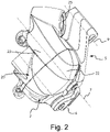
FIG. 2 is a view of some components of the derailleur ofFIG. 1 , according to another perspective, -
FIG. 3 is a partially exploded view of the components ofFIG. 2 , according to another perspective, -
FIG. 4 is a sectional view of the components ofFIG. 3 , -
FIGs. 5 and 6 show a member defining a pivot used in the derailleur ofFIG. 1 , in longitudinal section and in a lateral view, -
FIGs. 7 and 8 show an insert used in the derailleur ofFIG. 1 , in longitudinal section and in a lateral view, and -
FIGs. 9 and 10 show a blind bushing used in the derailleur ofFIG. 1 , in longitudinal section and in a lateral view. - In
FIG. 1 a bicycle electric/electronic derailleur 1, of the articulated parallelogram type, is shown. - In the case shown, it is a rear derailleur 1, but this is to be understood as being merely by way of an example, and the derailleur may be a front derailleur.
- The derailleur 1 comprises a
support body 2 configured to be attached to a bicycle frame, achain guide 3, and a pair of connectingarms support body 2 and thechain guide 3, forming a plurality of mutually movable components. The pair of connecting arms comprises a proximal connectingarm 4 and a distal connectingarm 5. For example, thesupport body 4 may be attached to the frame through a connection device so-called "articulated joint" 15. - The mutually
movable components - The connecting
arms support body 2 and to thechain guide 3 at respective geometric articulation axes: a support body-proximal connectingarm articulation axis 6, a support body-distal connectingarm articulation axis 7, a chain guide-proximal connectingarm articulation axis 8, and a chain guide-distal connectingarm articulation axis 9. - The electric derailleur 1 comprises a geared motor 10 (
FIG. 3 ,4 ). The gearedmotor 10 may be merely electric or electronic, when the derailleur also includes a data processing system controlling the gearedmotor 10 and any other electric/electronic components of the derailleur 1, for example comprising one or more components borne by one or more printed circuit boards or PCBs. As mentioned above, the gearedmotor 10 may also comprise a motor not coupled with any speed reducer. - The geared
motor 10 controls the mutual motion of the mutuallymovable components support body 2 and therefore to the bicycle frame- having at least one displacement component in the direction of the axis of the group of toothed wheels associated with the hub of the rear wheel or "sprocket assembly", so as to bring the transmission chain (or belt) into engagement with a predetermined toothed wheel or sprocket of the sprocket assembly. In the case of a front derailleur, the displacement of thechain guide 3 has at least one displacement component in the direction of the bottom bracket spindle, so as to bring the transmission chain (or belt) into engagement with a preselected toothed wheel or chainring of the "crankset". - The derailleur 1 further comprises an electric
power supply unit 12 comprising one or more secondary cells, for powering the gearedmotor 10 and any other electric/electronic devices. In the case shown, the electricpower supply unit 12 is shown supported by the proximal connectingarm 4, but different locations of the electricpower supply unit 12 are possible. - The electric
power supply unit 12 may also include at least one printed circuit board or PCB bearing electronic components controlling the electricpower supply unit 12. The electricpower supply unit 12 may therefore be a so-called smart battery. - The electric
power supply unit 12, possibly of the smart battery type, the data processing system for controlling the gearedmotor 10 and/or other electric/electronic devices represent examples of electric/electronic devices that, just as the gearedmotor 10, it is advisable to protect against dirt, water and other liquids. For the sake of simplicity, hereinafter reference will be made, in this respect, to the gearedmotor 10 only. - With reference also to
FIGs. 2-4 , in the case shown the gearedmotor 10 is housed in thesupport body 2, that has to be understood as illustrative of the first component mentioned in the introductory part of the present description. In those figures, for the sake of clarity thechain guide 3 is omitted. - In order to house the geared
motor 10, thesupport body 2 comprises acase 20 wherein achamber 21 is formed. Thecase 20 is formed by twoportions motor 10 and whatever else has to be housed in thechamber 21, are fixedly connected to each other, for example through thermo-welding, ultrasound welding, sealing, gluing etc. - In the present description and in the attached claims, a mechanical connection between two members is said to be "removable" if it allows them to be detached without the aid of tools, "permanent" if it allows them to be detached only with the aid of tools, and "fixed" it the detachment may only take place damaging at least one of the two members.
- The connection of the two
portions labyrinth seal 24 between their coupled edges, filled with resin, for example epoxy resin. - A
hole 25 made in thecase portion 22 and useful for attaching thesupport body 2 to the bicycle through the articulated joint 15 may also be recognized. - The geared
motor 10 is permanently connected, internally of thechamber 21, for example through screws, of which ascrew 26 is visible. In the case shown, the gearedmotor 10 is fixed to thecase portion 22. - In the case shown merely by way of an example, the
output shaft 30 of the gearedmotor 10 is at the support body-proximal connectingarm articulation axis 6. As shown, thechamber 21 thus crosses such articulation axis, that is one of the twoaxes 6, 7 - among said articulation axes 6, 7, 8, 9 - to which thesupport body 2 is articulated. The proximal connectingarm 4 should therefore be understood as illustrative of the second component mentioned in the introductory part of the present description. - The
output shaft 30 extends through a throughhole 31 of thecase 20, in particular made in thecase portion 22 to which the geared motor is permanently connected. - A
hermetic seal gasket 32 is provided between the throughhole 31 and theoutput shaft 30. For example, the throughhole 31 is a counterbored hole and thus it has afirst portion 33 contiguous to thechamber 21 having a diameter comparatively larger than asecond portion 34 thereof open outwards of thecase 20. Thehermetic seal gasket 32 is housed in thefirst portion 33, and is in interference fit with the lateral wall of the same, while theoutput shaft 30 may rotate dragging on thehermetic seal gasket 32. - The
output shaft 30 also extends, at a drivingend 35 thereof, through ahole 36 of the proximal connectingarm 4. Theoutput shaft 30 is in interference fit with thehole 36. In the case shown, thehole 36 of the proximal connectingarm 4 is a through hole, but it could also be a blind hole. In the case shown, thehole 36 is provided with areinforcement insert 37, that for example may be co-moulded with the rest of the proximal connectingarm 4. - The
output shaft 30 of the gearedmotor 10 does not extend through thecase 20 at itssecond end 38 opposed to the drivingend 35, and is thus shorter than the conventional configuration wherein theoutput shaft 30 is connected at both ends thereof with the driven connecting arm. Furthermore, theoutput shaft 30 of the gearedmotor 10 does not require any hole at itssecond end 38. The gearedmotor 10 is thus more compact and lighter and simpler to be made. - Along the
output shaft 30, adrum 39 of a so-called "(gearshift) release device" is also shown, having the function of disengaging theoutput shaft 30 of the gearedmotor 10 from the rest of the kinematic chain when the drive torque is excessive, for example in case of seizing of thechain guide 3, or in case of a shock acting from the outside on the connectingarms chain guide 5. Theoutput shaft 30 and thedrum 39 are interference fitted through, for example, an external knurl of the coupled portion of theoutput shaft 30. - The
case 20 comprises ablind hole 40 coaxial with the support body-proximal connectingarm articulation axis 6, open outwards of thecase 20. Theblind hole 40 is on the opposed side of thecase 20 with respect to the through hole 31 - namely, adjacent to the side of thesecond end 38 of theoutput shaft 30 of gearedmotor 10. - The
chamber 21 is closed at that position, so that no provision is necessary in order to ensure hermetic sealing thereof. - The proximal connecting
arm 4 comprises apivot 41 pivotable in theblind hole 40. Along the support body-proximal connecting arm (geometric)articulation axis 6, two "physical" articulation semiaxes are therefore defined, comprising the pair output shaft/throughhole pivot - In the case shown and with reference also to
FIGs. 5 and 6 , thepivot 41 is formed in amember 42 comprising a screwingtool engagement head 43, and ashank 44 extended from thehead 43. Aportion 45 of theshank 44 contiguous to thehead 43 is provided with an external threading, and the remainingportion 46 of theshank 44 is without threading. - The
portion 45 provided with external threading is screwed in an internally threaded throughhole 47 of the proximal connectingarm 4; theportion 46 without threading, that protrudes from the throughhole 47, forms saidpivot 41. - The
member 42 may be made of steel, for example of martensitic stainless steel, optionally solubilized and aged, in particular of martensitic stainless steel of class AISI 630 H1075 of the AISI, solubilized and aged at 1075°F. - The
member 42 may be subject to a blackening surface treatment, for aesthetic purposes. - In the case shown, the
head 43 is provided, merely by way of a non-limiting example, with anhexalobular recess 48 of the type present in the screws commercially known as Torx screws. - In the case shown and with reference also to
FIGs. 7 and 8 , the internally threaded throughhole 47 may be made in aninsert 50 of the proximal connectingarm 4. - The
insert 50 may be co-moulded in the proximal connectingarm 4. - The insert may be made of steel, for example of austenitic stainless steel, in particular of austenitic stainless steel of class AISI 304 of the AISI.
- In the case shown and with reference also to
FIGs. 9 and 10 , theblind hole 40 of thecase 20 may be provided with ablind bushing 51. - The
blind bushing 51 may be overprinted in the first component. - The
blind bushing 51 may be made of steel, for example of martensitic stainless steel, possibly solubilized and non-aged, in particular of martensitic stainless steel of class AISI 630 of the American Iron and Steel Institute (AISI), solubilized and non-aged. - The
blind bushing 51 may be subject to a surface chemical treatment to reduce the sliding friction coefficient of the pair blind hole/pivot - Turning back to
FIG. 4 , in the case shown thechamber 21 also crosses the support body-distal connectingarm articulation axis 7, that is the second of the twoarticulation axes support body 2 is articulated. - In the case shown, also along such support body-distal connecting arm (geometric)
articulation axis 7, two "physical" articulation semiaxis are defined, comprising in this case two pairs blind hole/pivot. - In detail, in the case shown the
case 20 comprises twoblind holes case 20, and the distal connectingarm 5 comprisespivots blind holes arm 5 should be meant as being illustrative of the third component mentioned in the introductory part of the present description. - However, only one of the two "physical" semiaxes could be defined by a pair blind hole/pivot, namely only the
blind hole 52 and thepivot 54 or only theblind hole 53 and thepivot 55 could be provided for. - As far as the embodiment of each of the two pairs blind hole/
pivot pivot - It is noted that instead of each of the pairs blind hole/
pivot support body 2 and the proximal connectingarm 4, respectively the distal connectingarm 5, may be made therein through other means, for example a through hole extended in a region of thecase 20 not crossing the chamber 21 (for example in a suitably arranged appendage or bracket) in which a pivot of the proximal connectingarm 4, respectively of the distal connectingarm 5, is pivotable, or a pivot of thesupport body 2 pivotable in a hole of the proximal connectingarm 4, respectively of the distal connectingarm 5. - Although it has been described with reference to a geared
motor 10 housed in thesupport body 2 havingoutput shaft 30 at the support body-proximal connectingarm articulation axis 6, the invention applies to other derailleur configurations. - So, the geared
motor 10 may be housed in thesupport body 2, but have theoutput shaft 30 at the support body-distal connectingarm articulation axis 7, using for example an opposed configuration of the pairs blind hole/pivot and drive shaft/through hole with respect to that shown, including all the variants and changes discussed above. - The geared
motor 10 may also be housed in thechain guide 3 and have theoutput shaft 30 at the chain guide-proximal connectingarm articulation axis 8 or at the chain guide-distal connectingarm articulation axis 9; it may be housed in the proximal connectingarm 4 and haveoutput shaft 30 at the chain guide-proximal connectingarm articulation axis 8 or at the support body-proximal connectingarm articulation axis 6; it may be housed in the distal connectingarm 5 and have theoutput shaft 30 at the support body-distal connectingarm articulation axis 7 or at the chain guide-distalconnecting arm 9 articulation axis; the configurations of the pairs blind hole/pivot and drive motor/through hole to be used in each case being clear in the light of the present description. - As mentioned above, alternatively or additionally to the hermetically
closed chamber 21 housing the geared motor 10 (besides any other electric/electronic devices), one or more of the other mutuallymovable components power supply unit 12 or the data processing system. In this case, one or more of the "physical" semiaxes corresponding to the two (geometric) articulation axes to which this component is articulated may be defined through pairs blind hole/pivot, the component thus having one to four blind holes. By providing for four pairs blind hole/pivot, if all the electric/electronic devices are housed in the chamber without the need for electric cables to pass, then the chamber is hermetically closed. In some cases, the chamber may still necessitate a through hole for electric cables to pass, but such a passage may be easily hermetically sealable through a suitable gasket. - When the component now described is considered as the first component under the terms used in the introductory part, for example when it is an alternative rather than an addition with respect to the provision, in a first component, of the hermetically
closed chamber 21 housing the gearedmotor 10, then one of the blind holes represents the first blind hole under the terms used in the introductory part, and the second blind hole under the terms used in the introductory part, coaxial with the first blind hole, may be or not be present. - In any case, as far as the embodiment of each of the -one to fourpairs blind hole/pivot is concerned, reference is made to the previous description of the embodiment of the pair blind hole/
pivot - As far as the embodiment of possible "physical" axes not defined by a respective pair blind hole/pivot is concerned, the above mentioned considerations apply.
- Last it is noted that the geared
motor 10 may also be arranged with itsoutput shaft 30 extended along the diagonal of the articulated parallelogram, in its own case: in that case all four mutuallymovable components - Summing up and generally stated, what has been described for the first component, whether it contains the geared
motor 10 or not, may be made also in one or more other components, so as to have plural hermetically closed chambers at disposal, with the structural restriction that each of the articulation axes is shared by two components. In practice, each of the second and third components -under the terms of the introductory part- may have whatever conformation along the articulation axis that it shares with the fourth component, but along the other articulation axes it should first of all feature the member matching that featured by the "first component". - Those skilled in the art will understand that the derailleur 1 may comprise other members and devices, among which for example the above mentioned "(gearshift) release device".
- Those skilled in the art will understand that the derailleur 1 may also have a shape even considerably different from that shown, and/or additional components not shown for the sake of simplicity.
- The secondary cells of the electric power supply unit may be recharged while the electric power supply unit is on board of the bicycle, by providing for suitable recharge connectors, and/or the electric power supply unit may be recharged in a recharge cradle after having been detached from the derailleur.
- The various embodiments, variants and/or possibilities of each component or group of components that have been described are to be meant as combinable with each other in any manner, unless they are mutually incompatible.
- The above is a description of various embodiments of inventive aspects, and further changes can be made without departing from the scope of the present invention. The shape and/or size and/or location and/or orientation of the various components and/or the succession of the various steps can be changed. The functions of an element or module can be carried out by two or more components or modules, and vice-versa. Components shown directly connected to or contacting each other can have intermediate structures arranged in between them. Steps shown directly following each other can have intermediate steps carried out between them. The details shown in a figure and/or described with reference to a figure or to an embodiment can apply in other figures or embodiments. Not all of the details shown in a figure or described in a same context must necessarily be present in a same embodiment. Features or aspects that turn out to be innovative with respect to the prior art, alone or in combination with other features, should be deemed to be described per se, irrespective of what is explicitly described as innovative.
Claims (12)
- Bicycle electric/electronic derailleur (1) comprising:- a plurality of mutually movable components (2, 3, 4, 5), comprising a support body (2) configured to be attached to a bicycle frame, a chain guide (3), and a pair of connecting arms (4, 5) comprising a proximal connecting arm (4) and a distal connecting arm (5), for connection between the support body (2) and the chain guide (3) at respective geometric articulation axes (6, 7, 8, 9), comprising a support body-proximal connecting arm articulation axis (6), a support body-distal connecting arm articulation axis (7), a chain guide-proximal connecting arm articulation axis (8), and a chain guide-distal connecting arm articulation axis (9),a geared motor (10) for controlling the mutual motion of the plurality of mutually movable components (2, 3, 4, 5),wherein at least one first component (2) of the mutually movable components (2, 3, 4, 5) comprises a case (20),wherein a chamber (21) containing said geared motor (10) and/or one or more electric/electronic devices is formed in said case (20), the chamber (21) crossing at least one first axis (6; 7) of the two among said articulation axes (6, 7, 8, 9) to which the first component (2) is articulated,characterized in that said case (20) comprises a first blind hole (40; 52) coaxial with said crossed first axis (6; 7) and open outwards of said case (20), and a second component (4; 5) of the mutually movable components (2, 3, 4, 5) articulated to the first component (2) at said crossed first axis (6; 7) comprises a pivot (41; 54) pivotable in the first blind hole (40; 52).
- Derailleur (1) according to claim 1, wherein the first blind hole (40; 52) of the case (20) is provided with a blind bushing (51).
- Derailleur (1) according to claim 2, wherein the blind bushing (51) is overprinted in the first component (2).
- Derailleur (1) according to any of the previous claims, wherein the pivot (41; 54) is formed in a member (42) comprising a screwing tool engagement head (43) and a shank (44) extending from the head (43), a portion (45) of the shank (44) contiguous to the head (43) being provided with an external threading and the remaining portion (46) of the shank (44) being without threading, wherein the portion (45) provided with external threading is screwed into an internally threaded through hole (47) of the second component, the portion (46) without threading protruding from the through hole (47) forming said pivot (41; 54).
- Derailleur (1) according to claim 4, wherein the internally threaded through hole (47) is made in an insert (50) of the second component (4; 5).
- Derailleur (1) according to claim 5, wherein the insert (50) is co-moulded in the second component (4; 5).
- Derailleur (1) according to any of the previous claims, wherein the case (20) comprises a second blind hole (53) coaxial with said first crossed axis (6) and open outwards on one side of said case (20) opposed with respect to the first blind hole (52), the second component (5) comprising a second pivot (55) pivotable in the second blind hole (53).
- Derailleur (1) according to any of claims 1-6, wherein the chamber (21) contains said geared motor (10) and possibly said one or more electric/electronic devices, wherein said case (20) further comprises a through hole (31) coaxial with said first crossed axis (7), the through hole (31) being on the opposite side of said case (20) with respect to the first blind hole (40), an output shaft (30) of the geared motor (10) extending through the through hole (31) and through a hole (36) of the second component (4), a hermetic seal gasket (32) being provided for between the through hole (31) and the output shaft (30).
- Derailleur (1) according to any of the previous claims, wherein the chamber (21) crosses both articulation axes (6; 7) to which the first component (2) is articulated, wherein said case (20) comprises one or two additional blind holes (52, 53), coaxial with the second crossed axis (7; 6), a third component (5) of the mutually movable components (2, 3, 4, 5) articulated to the first component (2) at said second crossed axis (7; 6) comprising one or respectively two pivot(s) (54, 55) pivotable in said one or two additional blind hole(s) (52, 53).
- Derailleur (1) according to any of the previous claims, wherein said one or more electric/electronic devices comprise(s) an electric power supply unit, preferably of the secondary cell battery type, and/or one or more components controlling the geared motor (10) and/or the electric power supply unit, if provided for.
- Derailleur (1) according to any of the previous claims, wherein the first component (2) is the support body.
- Derailleur (1) according to any of the previous claims, wherein the derailleur is a rear derailleur.
Applications Claiming Priority (1)
| Application Number | Priority Date | Filing Date | Title |
|---|---|---|---|
| IT102021000024737A IT202100024737A1 (en) | 2021-09-28 | 2021-09-28 | ARTICULATED PARALLELOGRAM ELECTRIC/ELECTRONIC BICYCLE DERAILLEUR |
Publications (2)
| Publication Number | Publication Date |
|---|---|
| EP4155186A1 true EP4155186A1 (en) | 2023-03-29 |
| EP4155186B1 EP4155186B1 (en) | 2026-03-04 |
Family
ID=78771076
Family Applications (1)
| Application Number | Title | Priority Date | Filing Date |
|---|---|---|---|
| EP22197993.3A Active EP4155186B1 (en) | 2021-09-28 | 2022-09-27 | Bicycle electric/electronic derailleur of the articulated parallelogram type |
Country Status (5)
| Country | Link |
|---|---|
| US (1) | US11753109B2 (en) |
| EP (1) | EP4155186B1 (en) |
| CN (1) | CN115871861A (en) |
| IT (1) | IT202100024737A1 (en) |
| TW (1) | TW202319290A (en) |
Cited By (1)
| Publication number | Priority date | Publication date | Assignee | Title |
|---|---|---|---|---|
| US12024263B2 (en) | 2022-05-13 | 2024-07-02 | Campagnolo S.R.L. | Articulated parallelogram bicycle electric/electronic derailleur |
Families Citing this family (5)
| Publication number | Priority date | Publication date | Assignee | Title |
|---|---|---|---|---|
| USD1038844S1 (en) * | 2020-12-22 | 2024-08-13 | Marcin GOLEC | Chain-guide for cycle gear |
| US11713095B2 (en) * | 2021-05-07 | 2023-08-01 | Sram, Llc | Bicycle derailleur |
| US11787505B1 (en) * | 2022-04-12 | 2023-10-17 | Shimano Inc. | Linkage and derailleur for human-powered vehicle |
| DE102022204093A1 (en) | 2022-04-27 | 2023-11-02 | Shimano Inc. | DERAILLEUR FOR A HUMAN POWERED VEHICLE |
| US12617492B1 (en) * | 2025-02-26 | 2026-05-05 | Tien Hsin Industries Co., Ltd. | Electronic derailleur |
Citations (3)
| Publication number | Priority date | Publication date | Assignee | Title |
|---|---|---|---|---|
| US20180001960A1 (en) | 2016-07-04 | 2018-01-04 | Campagnolo S.R.L. | Bicycle electric front derailleur |
| US20190144071A1 (en) * | 2017-11-09 | 2019-05-16 | Sram Deutschland Gmbh | Electromechanical derailleur |
| US20200255089A1 (en) * | 2012-09-27 | 2020-08-13 | Sram, Llc | Rear derailleur |
Family Cites Families (19)
| Publication number | Priority date | Publication date | Assignee | Title |
|---|---|---|---|---|
| US6203459B1 (en) * | 1997-07-25 | 2001-03-20 | John L. Calendrille, Jr. | Bicycle derailleur system with integral flexible seal to protect moving parts from contaminants |
| DE102005034330A1 (en) * | 2005-07-22 | 2007-01-25 | Sram Deutschland Gmbh | articulation |
| ITUA201696738U1 (en) * | 2016-05-04 | 2017-11-04 | Campagnolo Srl | ACTUATOR DEVICE FOR A BICYCLE CHANGE AND ITS BICYCLE CHANGE. |
| TWM562815U (en) * | 2018-04-03 | 2018-07-01 | 彥豪金屬工業股份有限公司 | Derailleur assembly |
| TWM562816U (en) * | 2018-04-03 | 2018-07-01 | 彥豪金屬工業股份有限公司 | Derailleur assembly |
| US11661139B2 (en) * | 2018-04-11 | 2023-05-30 | Sram, Llc | Electromechanical control device and methods for electromechanical control of a bicycle |
| US11428279B2 (en) * | 2018-11-26 | 2022-08-30 | Fox Factory, Inc. | Suspension enhancing hub and rear derailleur assembly |
| US11459061B2 (en) * | 2019-01-12 | 2022-10-04 | Sram, Llc | Bicycle component motion control |
| US11015705B2 (en) * | 2019-01-18 | 2021-05-25 | Sram, Llc | Bicycle control system |
| DE102020000827A1 (en) * | 2019-04-25 | 2020-10-29 | Sram Deutschland Gmbh | Electromechanical switching mechanism for coaxial assembly |
| US11840315B2 (en) * | 2019-05-02 | 2023-12-12 | Sram, Llc | Gear changer adjustment and device |
| US11608139B2 (en) * | 2019-05-13 | 2023-03-21 | Shimano Inc. | Bicycle rear derailleur |
| TWI719705B (en) * | 2019-11-06 | 2021-02-21 | 天心工業股份有限公司 | Rear derailleur |
| TWI712547B (en) * | 2019-11-06 | 2020-12-11 | 天心工業股份有限公司 | Rear derailleur |
| TWI729556B (en) * | 2019-11-06 | 2021-06-01 | 天心工業股份有限公司 | Rear derailleur |
| US11535338B2 (en) * | 2020-06-16 | 2022-12-27 | Tien Hsin Industries Co., Ltd. | Electronic rear derailleur |
| US11685469B2 (en) * | 2020-09-11 | 2023-06-27 | Shimano Inc. | Bicycle derailleur |
| US12384491B2 (en) * | 2021-05-07 | 2025-08-12 | Sram, Llc | Bicycle derailleur |
| EP4685043A1 (en) * | 2021-06-29 | 2026-01-28 | SRAM Deutschland GmbH | Modular bicycle derailleur |
-
2021
- 2021-09-28 IT IT102021000024737A patent/IT202100024737A1/en unknown
-
2022
- 2022-09-20 TW TW111135461A patent/TW202319290A/en unknown
- 2022-09-26 CN CN202211172265.0A patent/CN115871861A/en active Pending
- 2022-09-27 EP EP22197993.3A patent/EP4155186B1/en active Active
- 2022-09-27 US US17/954,009 patent/US11753109B2/en active Active
Patent Citations (4)
| Publication number | Priority date | Publication date | Assignee | Title |
|---|---|---|---|---|
| US20200255089A1 (en) * | 2012-09-27 | 2020-08-13 | Sram, Llc | Rear derailleur |
| US20180001960A1 (en) | 2016-07-04 | 2018-01-04 | Campagnolo S.R.L. | Bicycle electric front derailleur |
| EP3266694A1 (en) | 2016-07-04 | 2018-01-10 | Campagnolo S.R.L. | Bicycle electric front derailleur |
| US20190144071A1 (en) * | 2017-11-09 | 2019-05-16 | Sram Deutschland Gmbh | Electromechanical derailleur |
Cited By (1)
| Publication number | Priority date | Publication date | Assignee | Title |
|---|---|---|---|---|
| US12024263B2 (en) | 2022-05-13 | 2024-07-02 | Campagnolo S.R.L. | Articulated parallelogram bicycle electric/electronic derailleur |
Also Published As
| Publication number | Publication date |
|---|---|
| EP4155186B1 (en) | 2026-03-04 |
| IT202100024737A1 (en) | 2023-03-28 |
| CN115871861A (en) | 2023-03-31 |
| US11753109B2 (en) | 2023-09-12 |
| US20230099532A1 (en) | 2023-03-30 |
| TW202319290A (en) | 2023-05-16 |
Similar Documents
| Publication | Publication Date | Title |
|---|---|---|
| EP4155186B1 (en) | Bicycle electric/electronic derailleur of the articulated parallelogram type | |
| US20260098572A1 (en) | Front gear changer | |
| CN1821014B (en) | Motorized bicycle derailleur assembly | |
| US5433284A (en) | Electrical bicycle | |
| TWI756650B (en) | Bicycle rear derailleur | |
| CN107571961B (en) | Electric front speed variator for bicycle | |
| US20050187048A1 (en) | Gear reduction apparatus for a bicycle component | |
| US10239579B2 (en) | Bicycle electric rear derailleur | |
| US12024263B2 (en) | Articulated parallelogram bicycle electric/electronic derailleur | |
| US5569104A (en) | Electronic transmission control for human powered vehicle | |
| US7341532B2 (en) | Electric derailleur motor unit | |
| US9381974B2 (en) | Electric derailleur motor unit and motorized derailleur | |
| US10696358B2 (en) | Electric bicycle derailleur | |
| EP3165439B1 (en) | Power supply for a bicycle derailleur | |
| EP1588934A2 (en) | Electric bicycle derailleur | |
| EP2189367A1 (en) | Bicycle rear derailleur | |
| JP2008222211A (en) | Electric derailluer for bicycle | |
| US10589821B2 (en) | Bicycle chain device | |
| US20160318582A1 (en) | Gear transmission and derailleur system | |
| ATE383304T1 (en) | BICYCLE GEAR GEARS | |
| US20210403124A1 (en) | Bicycle derailleur and link pin for bicycle derailleur | |
| EP0800988B1 (en) | Bicycle with electric drive mechanism | |
| EP3333062B1 (en) | Straddled electric vehicle | |
| EP0089129B1 (en) | A power transmission mechanism with a backlash regulator for industrial robots | |
| EP4309989B1 (en) | Bicycle derailleur |
Legal Events
| Date | Code | Title | Description |
|---|---|---|---|
| PUAI | Public reference made under article 153(3) epc to a published international application that has entered the european phase |
Free format text: ORIGINAL CODE: 0009012 |
|
| STAA | Information on the status of an ep patent application or granted ep patent |
Free format text: STATUS: THE APPLICATION HAS BEEN PUBLISHED |
|
| AK | Designated contracting states |
Kind code of ref document: A1 Designated state(s): AL AT BE BG CH CY CZ DE DK EE ES FI FR GB GR HR HU IE IS IT LI LT LU LV MC MK MT NL NO PL PT RO RS SE SI SK SM TR |
|
| P01 | Opt-out of the competence of the unified patent court (upc) registered |
Effective date: 20230516 |
|
| STAA | Information on the status of an ep patent application or granted ep patent |
Free format text: STATUS: REQUEST FOR EXAMINATION WAS MADE |
|
| 17P | Request for examination filed |
Effective date: 20230925 |
|
| RBV | Designated contracting states (corrected) |
Designated state(s): AL AT BE BG CH CY CZ DE DK EE ES FI FR GB GR HR HU IE IS IT LI LT LU LV MC MK MT NL NO PL PT RO RS SE SI SK SM TR |
|
| GRAP | Despatch of communication of intention to grant a patent |
Free format text: ORIGINAL CODE: EPIDOSNIGR1 |
|
| STAA | Information on the status of an ep patent application or granted ep patent |
Free format text: STATUS: GRANT OF PATENT IS INTENDED |
|
| INTG | Intention to grant announced |
Effective date: 20251002 |
|
| GRAS | Grant fee paid |
Free format text: ORIGINAL CODE: EPIDOSNIGR3 |
|
| GRAA | (expected) grant |
Free format text: ORIGINAL CODE: 0009210 |
|
| STAA | Information on the status of an ep patent application or granted ep patent |
Free format text: STATUS: THE PATENT HAS BEEN GRANTED |
|
| AK | Designated contracting states |
Kind code of ref document: B1 Designated state(s): AL AT BE BG CH CY CZ DE DK EE ES FI FR GB GR HR HU IE IS IT LI LT LU LV MC MK MT NL NO PL PT RO RS SE SI SK SM TR |
|
| REG | Reference to a national code |
Ref country code: CH Ref legal event code: F10 Free format text: ST27 STATUS EVENT CODE: U-0-0-F10-F00 (AS PROVIDED BY THE NATIONAL OFFICE) Effective date: 20260304 Ref country code: GB Ref legal event code: FG4D |
|
| REG | Reference to a national code |
Ref country code: DE Ref legal event code: R096 Ref document number: 602022031513 Country of ref document: DE |
|
| REG | Reference to a national code |
Ref country code: IE Ref legal event code: FG4D |