EP4155183A1 - Bicycle equipment provided with an electric power supply unit - Google Patents
Bicycle equipment provided with an electric power supply unit Download PDFInfo
- Publication number
- EP4155183A1 EP4155183A1 EP22197992.5A EP22197992A EP4155183A1 EP 4155183 A1 EP4155183 A1 EP 4155183A1 EP 22197992 A EP22197992 A EP 22197992A EP 4155183 A1 EP4155183 A1 EP 4155183A1
- Authority
- EP
- European Patent Office
- Prior art keywords
- slider
- power supply
- supply unit
- electric power
- component
- Prior art date
- Legal status (The legal status is an assumption and is not a legal conclusion. Google has not performed a legal analysis and makes no representation as to the accuracy of the status listed.)
- Granted
Links
Images



Classifications
-
- B—PERFORMING OPERATIONS; TRANSPORTING
- B62—LAND VEHICLES FOR TRAVELLING OTHERWISE THAN ON RAILS
- B62J—CYCLE SADDLES OR SEATS; AUXILIARY DEVICES OR ACCESSORIES SPECIALLY ADAPTED TO CYCLES AND NOT OTHERWISE PROVIDED FOR, e.g. ARTICLE CARRIERS OR CYCLE PROTECTORS
- B62J43/00—Arrangements of batteries
- B62J43/30—Arrangements of batteries for providing power to equipment other than for propulsion
-
- B—PERFORMING OPERATIONS; TRANSPORTING
- B62—LAND VEHICLES FOR TRAVELLING OTHERWISE THAN ON RAILS
- B62J—CYCLE SADDLES OR SEATS; AUXILIARY DEVICES OR ACCESSORIES SPECIALLY ADAPTED TO CYCLES AND NOT OTHERWISE PROVIDED FOR, e.g. ARTICLE CARRIERS OR CYCLE PROTECTORS
- B62J43/00—Arrangements of batteries
- B62J43/20—Arrangements of batteries characterised by the mounting
-
- B—PERFORMING OPERATIONS; TRANSPORTING
- B62—LAND VEHICLES FOR TRAVELLING OTHERWISE THAN ON RAILS
- B62M—RIDER PROPULSION OF WHEELED VEHICLES OR SLEDGES; POWERED PROPULSION OF SLEDGES OR SINGLE-TRACK CYCLES; TRANSMISSIONS SPECIALLY ADAPTED FOR SUCH VEHICLES
- B62M9/00—Transmissions characterised by use of an endless chain, belt, or the like
- B62M9/04—Transmissions characterised by use of an endless chain, belt, or the like of changeable ratio
- B62M9/06—Transmissions characterised by use of an endless chain, belt, or the like of changeable ratio using a single chain, belt, or the like
- B62M9/10—Transmissions characterised by use of an endless chain, belt, or the like of changeable ratio using a single chain, belt, or the like involving different-sized wheels, e.g. rear sprocket chain wheels selectively engaged by the chain, belt, or the like
- B62M9/12—Transmissions characterised by use of an endless chain, belt, or the like of changeable ratio using a single chain, belt, or the like involving different-sized wheels, e.g. rear sprocket chain wheels selectively engaged by the chain, belt, or the like the chain, belt, or the like being laterally shiftable, e.g. using a rear derailleur
- B62M9/121—Rear derailleurs
- B62M9/122—Rear derailleurs electrically or fluid actuated; Controls thereof
-
- B—PERFORMING OPERATIONS; TRANSPORTING
- B62—LAND VEHICLES FOR TRAVELLING OTHERWISE THAN ON RAILS
- B62M—RIDER PROPULSION OF WHEELED VEHICLES OR SLEDGES; POWERED PROPULSION OF SLEDGES OR SINGLE-TRACK CYCLES; TRANSMISSIONS SPECIALLY ADAPTED FOR SUCH VEHICLES
- B62M9/00—Transmissions characterised by use of an endless chain, belt, or the like
- B62M9/04—Transmissions characterised by use of an endless chain, belt, or the like of changeable ratio
- B62M9/06—Transmissions characterised by use of an endless chain, belt, or the like of changeable ratio using a single chain, belt, or the like
- B62M9/10—Transmissions characterised by use of an endless chain, belt, or the like of changeable ratio using a single chain, belt, or the like involving different-sized wheels, e.g. rear sprocket chain wheels selectively engaged by the chain, belt, or the like
- B62M9/12—Transmissions characterised by use of an endless chain, belt, or the like of changeable ratio using a single chain, belt, or the like involving different-sized wheels, e.g. rear sprocket chain wheels selectively engaged by the chain, belt, or the like the chain, belt, or the like being laterally shiftable, e.g. using a rear derailleur
- B62M9/131—Front derailleurs
- B62M9/132—Front derailleurs electrically or fluid actuated; Controls thereof
Definitions
- the present invention relates in general to a bicycle equipment provided with an electric power supply unit.
- Bicycle electric/electronic pieces of equipment which require an electric power supply unit typically of the secondary cell battery type, comprise for example a derailleur associated with the bottom bracket spindle, a derailleur associated with the hub of the rear wheel, a suspension, a saddle setting adjuster, a lighting system, a satellite navigator, a training device, an anti-theft device, a cycle computer capable of providing information on the status of the bicycle, of the cyclist and/or of the route, a torque or power meter, a motor of a pedal assisted bicycle, a manual control device of another equipment, and others.
- equipment a set of components mechanically coupled with each other and configured to be attached to the bicycle in a single location is meant to be understood.
- the equipment may comprise for example a derailleur or a manual control device for a derailleur attachable to the handlebars or in proximity thereto, but not the assembly of both.
- electric/electronic is used to indicate an electric device that may also include electronic components and/or a data processing system.
- the electric power supply unit is typically removably attached to the bicycle equipment, in order to allow recharge thereof from the mains (possibly through a recharge saddle) besides any possibility of recharging it on board of the bicycle and/or in order to allow replacement thereof in case of performance degradation.
- a mechanical connection between two members is called “removable” if it allows them to be detached without the aid of tools.
- the technical problem at the basis of the invention is to provide a bicycle equipment with an electric power supply unit which may be attached and detached in an easy, quick and reliable manner despite the conditions of dirt and humidity to which the equipment is subject; desirably the weight and cost associated with the elements intended for removable attachment of the electric power supply unit should be contained.
- the invention relates to an electrically powered bicycle equipment, comprising:
- the Applicant has recognised that the local deformation of the gasket towards the bottom of the peripheral groove, establishing a gap between the gasket and the inner wall of the blind hole of the sliding seat, counteracts the establishment of an overpressure in the blind hole itself, whereby the resistance offered by the sliding seat against the push of the slider in rearward direction (in order to open the latch and thus release the electric power supply unit or allow seating thereof) is not increased by the overpressure, thus requiring less physical effort with the finger.
- the gap acts as a vent for air from the blind hole during the push on the slider, favouring expulsion of dust particles, dirt and water possibly present in the proximity of the mouth of the blind hole of the sliding seat, hindering entry thereof in the blind hole of the seat where they could jam or in any case hinder the correct operation of the latch assembly: thus not only the gap is not detrimental for the hermetic sealing function, rather it enhances that function.
- the depth of the intermediate section may be continuously variable from a maximum depth value at its center to a depth value of the two aligned sections.
- the latch assembly may comprise elastic means urging the slider towards the advanced position, in particular at least one compression spring housed in the blind hole and acting by pushing on the back of the slider.
- elastic means urging the slider towards the advanced position, in particular at least one compression spring housed in the blind hole and acting by pushing on the back of the slider.
- said one or more compression springs is/are provided for, the problem of inlet of dirt and humidity in the blind hole is particularly felt.
- Said at least one region of the back of the slider may also comprise two regions of the back of the slider, in particular two opposed regions.
- the back of the slider may have, in cross-section, an oval shape.
- valve shape a rounded and slightly elongate shape is meant to be understood. More specifically, under “oval” a closed plane line enclosing a convex plane region and provided in any point with a tangent straight line that is continually variable, for example an ellipse, is meant to be understood.
- said at least one region of the back of the slider is, for example, comprised in at least one longest side of the oval cross-section.
- the sliding seat may further comprise a guide channel contiguous to the blind hole, the guide channel having a sliding bottom for the slider, the bottom being formed on said one of the electric power supply unit and the component.
- the guide channel has a longitudinal direction extending along the sliding direction.
- the slider may have a control region sliding along the guide channel.
- the control region may have a finger resting surface, which may have the concavity towards the head of the slider.
- a crosspiece may be provided for, the head of the slider being in sliding and/or rolling coupling with the crosspiece.
- the crosspiece is effective to hold the slider on the bottom of the guide channel.
- crosspiece a member extending orthogonally to the sliding direction and spaced from and parallel to the bottom of the channel is meant to be indicated.
- the crosspiece may be a non-pivotable pin, with sliding friction between the crosspiece and the head, or a pin pivotable about its ow longitudinal axis, with rolling friction between pin and head.
- the head of the slider may form a step with the control region of the slider, the riser of the step abutting against the crosspiece in the fully advanced position of the slider.
- the crosspiece then also plays the role of limiter of the slider and provides a tactile and acoustic feeling to the operator because the stop of the slider is determined by the sudden shock of the riser on the pin.
- the retaining seat formed in said other one of the electric power supply unit and the component may define an abutment or limiter surface configured to receive, in abutment and pushing relationship, a surface of the head facing away from said one of the electric power supply unit and the component. In this manner the latch assembly is effective to retain the electric power supply unit against removal from the component.
- the retaining seat may further define at least one second abutment surface configured to receive, in abutment and pushing relationship, another surface of the head, facing toward said one of the electric power supply unit and the component or facing laterally with respect to said one of the electric power supply unit and the component, for example the surface sliding on the bottom of the channel and/or a surface of the head not parallel to the bottom of the channel.
- the retaining seat is effective to retain the electric power supply unit against movements also in other oriented directions, in particular against movements along the direction transverse to the guide channel.
- the attachment/detachment seat formed on the component may be configured to retain at least one region of the electric power supply unit, substantially opposed to a region involved by the latch assembly, against removal from the component at least in a second way of the retaining direction, opposed to the first way.
- At least one second latch assembly may be provided for in said region of the electric power supply unit substantially opposed to the region involved by the latch assembly.
- the attachment/detachment seat formed on the component may comprise at least one sliding guide of the electric power supply unit along the retaining direction, and/or at least one of the electric power supply unit and the attachment/detachment seat may comprise at least one pilot member.
- cavity is broadly meant to encompass a through cavity and a blind cavity or recess.
- the retaining direction may be the vertical direction and the first way may be downwards in the condition wherein the bicycle equipment is mounted on the bicycle and with the bicycle in the condition of straight travel on level ground. In this manner, the electric power supply unit is held suspended by the latch assembly.
- the matching electric contacts may be provided for on paired surfaces of the electric power supply unit and of the component, extending substantially orthogonal to the retaining direction.
- the electric contacts of one and a same between the electric power supply unit and the component may be of the pogo pin type.
- the ground electric contact may be more outcropping than the other electric contacts.
- the matching electric contacts may be arranged in a protrusion and a cavity having complementary shapes.
- the pogo pin contacts may be arranged in a cavity so as not to protrude when the electric power supply unit is not seated.
- the protrusion may have a peripheral groove, a hermetic seal gasket extending in said peripheral groove.
- the bicycle equipment may be a derailleur comprising:
- chain guide is used to indicate the component which, overall, is moved with respect to the support body and to the connecting arms; in the case of a rear derailleur it may include a first member articulated in the articulated parallelogram, sometimes called “bottom body”, and a second member movable therewith, sometimes called “rocker arm”, while in the case of a front derailleur it typically comprises a single member, sometimes called "cage”.
- geared motor a motor not coupled with any speed reducer is meant to be encompassed.
- the derailleur is, for example, a rear derailleur.
- the preselected component is, for example, a connecting arm, in particular the proximal connecting arm.
- the electric power supply unit turns out to be particularly protected against shocks to which it is subject during the travel of the bicycle.
- the derailleur may be a front derailleur, the preselected component being for example the support body.
- the geared motor may be housed in a second component of the plurality of mutually movable components different from the preselected component, for example in the support body when the preselected component is a connecting arm, an electric connection being provided for, extended between the contacts of the attachment/detachment seat and the second component.
- the geared motor may be housed in the preselected component, for example geared motor and electric power supply unit may both be housed in the support body.
- the derailleur may also include a data processing system, controlling the geared motor and any other electric/electronic components of the derailleur.
- the data processing system may comprise electric components and/or discrete electronic components and/or a micro-controller, which may also integrate memory means.
- the data processing system may be borne for example on at least one printed circuit board or PCB.
- the derailleur may thus be electronic.
- FIGs. 1-2 an illustrative bicycle equipment 1 is shown, provided with an electric power supply unit 2.
- the bicycle equipment 1 is a rear derailleur 3 comprising a support body 4 configured to be attached to a bicycle frame, a chain guide 5 and a pair of connecting arms 6, 7 extended between the support body 4 and the chain guide 5, forming a plurality of mutually movable components and in particular an articulated parallelogram.
- the pair of connecting arms comprises a proximal connecting arm 6 and a distal connecting arm 7.
- adjectives such as "proximal” and “distal” refer to the mounted condition of the derailleur on the bicycle. In particular, "proximal” is used to indicate closer to the frame and adjective “distal” is used to indicate farther from the frame.
- the derailleur 3 comprises a geared motor 9.
- the geared motor 9 may be purely electric or electronic, when the derailleur 3 also includes a data processing system controlling the geared motor and any other electric/electronic components of the derailleur 3, for example comprising one or more components borne by one or more printed circuit boards or PCBs.
- the geared motor may also comprise a motor not coupled with any speed reducer.
- the geared motor controls the mutual motion between chain guide 5 and support body 4, in particular determines the aperture and closure of the articulated parallelogram, and therefore a displacement of the chain guide 5 having at least one displacement component in the direction of the axis of the group of toothed wheels associated with the hub of the rear wheel or "sprocket assembly", so as to bring the transmission chain or belt into engagement with a predetermined toothed wheel or sprocket of the sprocket assembly.
- the geared motor 9 is for example housed in the support body 4 and controls the rotation of one of the connecting arms 6, 7 (in the case shown, the proximal connecting arm 6) about a pivotal axis thereof to the support body 4.
- the geared motor 9 is shown directly coupled with the proximal connecting arm 6, but this is not strictly necessary.
- the support body 4 may be attached to the frame through a connecting device so-called "articulated joint" 8.
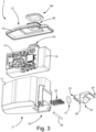
- the electric power supply unit 2 comprises one or more secondary cells 10 and a hermetic case housing said one or more secondary cells 10, formed for example by a container 11 and a cover 12.
- the electric power supply unit 2 may also include at least one printed circuit board or PCB 13 bearing electronic components controlling the electric power supply unit 2, housed in the hermetic case.
- the electric power supply unit 2 may therefore also be a so-called smart battery.
- the electric power supply unit 2 is removably attached to the derailleur 3, and it is shown in the detached condition in FIG. 4 .
- a component of the derailleur 3, the proximal connecting arm 6 in the case shown has an attachment/detachment seat 21 for the electric power supply unit 2.
- the component having the seat 21 for the electric power supply unit 2 is not necessarily the proximal connecting arm 6 and therefore hereinafter the component provided with the seat 21 will be referred to as component 20.
- At least one latch assembly 22 for holding the electric power supply unit 2 in the seated state, on the component 20, is provided for, wherein the electric power supply unit 2 is arranged in the attachment/detachment seat 21.
- the electric power supply unit 2 is firmly held on the derailleur 3 despite the vibrations and shocks to which it is subject during the bicycle travel.
- the latch assembly 22 first comprises a slider 23 having a head 24 and a back 25 opposed to the head 24.
- the electric power supply unit 2 has a sliding seat 26 of the slider 23 along a sliding direction X ( FIG. 8 ), and the component 20 has a retaining seat 27 of the head 24 against a displacement at least in a first way of a retaining direction Y (cf. the positive direction of the axis Y emphasised in FIG. 8 ), in the seated state of the electric power supply unit 2 and in the latched condition of the latch assembly 22.
- the retaining seat 27 is formed by a cavity that defines an abutment surface or limiter 29 configured to receive, in abutment and pushing relationship, a first surface 30 of the head 24.
- the surfaces 29, 30 are shown flat and orthogonal to the retaining direction Y, but they could deviate from such a shape.
- the slider 23 slides in the sliding seat 26 between a fully advanced position ( FIGs. 4 , 7 , 8 ) wherein the head 24 protrudes from the sliding seat 26 in order to be able to insert - in said seated state of the electric power supply unit 2 on the component 20 - in the retaining seat 27, and a fully retracted position ( FIGs. 5 , 6 , 11 ) wherein the head 24 does not protrude from the sliding seat 26 - allowing the seating of the electric power supply unit 2 in the component 20 or vice versa the extraction thereof from the attachment/detachment seat 21 for removal from the component 20.
- the sliding seat 26 comprises a blind hole 31.
- the blind hole 31 and the back 25 of the slider 23 have complementary shapes in a section transverse to the sliding direction X.
- the blind hole 31 is sized to receive the back 25 of the slider 23 in a sliding manner.
- the latch assembly 22 comprises a plurality of side-by-side compression springs 32, housed in the blind hole 31 and acting by pushing on the back 25 of the slider 23, for urging the slider 23 towards the advanced position.
- the sliding seat 26 further comprises a guide channel 33 contiguous to the blind hole 31.
- the bottom 34 of the guide channel 33 that provides a sliding surface for the slider 23, is formed on the electric power supply unit 2.
- the guide channel 33 is open outwards with respect to the electric power supply unit 2.
- the guide channel has a longitudinal direction extended along the sliding direction X.
- the first surface 30 of the head 24 is opposed to a second surface 35 of the head 24, that is slidingly coupled on the bottom 34 of the guide channel 33.
- the slider 23 has, in the case shown, a control region 36, sliding along the guide channel 33.
- the control region 36 may have, as shown, a finger resting surface 37 that has the concavity towards the head 24 of the slider 23.
- the control region 37 may have a cavity 38 open towards the bottom 34 of the guide channel 33, for reasons of moulding and lightening.
- a crosspiece 39 is provided for, in the case shown.
- the crosspiece 39 extends in a transverse direction Z ( FIG. 8 ) with respect to the sliding direction X, and is parallel to the bottom 34 of the guide channel 33, spaced therefrom.
- the crosspiece 39 is effective to hold the head 24 of the slider 23 on the bottom 34 of the guide channel 33.
- the head 24 and in particular its first surface 30 may be in sliding fit with the crosspiece 39.
- the crosspiece 39 is formed by a pin.
- the friction between the crosspiece 39 and the head 24 is sliding friction.
- the crosspiece 39 may also be formed by a pin pivotable about its own longitudinal axis, so that it turns out to be in rolling coupling with the first surface 30 of the head 24; in this manner the friction between the crosspiece 39 and the head 24 is rolling friction.
- the head 24 of the slider 23 forms, in the case shown, a step 40 with the control region 36 of the slider 23, the riser 41 of the step abutting against the crosspiece 39 in the fully advanced position of the slider 23.
- the crosspiece 39 thus also plays the role of limiter of the slider 23 and provides a tactile and acoustic feeling to the operator because the stop of the slider 23 is determined by the sudden shock of the riser 41 on the crosspiece 39.
- the slider 23 in order to release the latch assembly 22, the slider 23 has to be pushed in the direction of the arrow shown in FIGs. 5 and 6 , for example acting on the finger resting surface 37 of the control region 36. That pushing action has to overcome the resistance offered by the sliding seat 26, caused by the compression springs 32 if present, and in any case by the friction at play between the sliding and/or rolling coupling parts mentioned above, as well as possibly by the weight of the slider 23 itself in the case in which the sliding direction has a vertically upwards component.
- the Applicant has recognized that the blind hole 31, if on the one side it protects the slider 23 and any compression springs 32 better than a through hole, is subject to the entry of dirt and humidity that may have as a consequence the jamming of the slider 23 and damaging or rusting of any compression springs 32. Furthermore, during the push of the slider 23, air is compressed by the slider 23 inside the blind hole 31, so that an overpressure establishes in the blind hole 31, tending to increase the resistance offered by the sliding seat 26, what not only increases the physical effort by the user, but also entails the risk of breaking the slider 23 or the need to make it stronger and heavier.
- the latch assembly 22 may be configured as described hereinafter.
- the back 25 of the slider 23 has a closed-loop peripheral groove 50 or peripheral throat ( FIG. 3 ) (namely that runs all around the outer surface of the back 25).
- a ring gasket 51 for example an O-ring, is housed in the peripheral groove 50.
- the groove 50 does not have a constant depth along its extension, as evident in FIGs. 10 and 13 .
- the groove 50 has two aligned shallow portions 53, 54 and a deeper portion 55 intermediate therebetween.
- the depth of the portion 55 may be continually variable from a maximum depth value P2 at the centre to the depth value P1 of the two aligned sections 53, 54 as shown, but this is not strictly necessary.
- the portion 55 is formed by a recess in the groove 50 substantially rounded and symmetric (considered in the cross-section of the slider 23), but this is not strictly necessary.
- the back 25 of the slider 23, as well as the inner wall of the blind hole 31 wherein it slides, has, in cross-section, an oval and in particular elliptical shape.
- the region 52 is comprised in a longest side of the oval/elliptical section, but this is not necessary.
- the shape of the slider 23 may also be polygonal (for example square) with rounded edges or even substantially circular.
- the bottom of the peripheral groove 50 defines a concave plane figure in the plane of the drawing, transversal to the sliding direction X.
- concave plane figure it is meant that at least two points of the figure are ends of a segment that is not entirely contained inside the figure.
- the gasket 51 mounted with adequate tension in the peripheral groove 50, is only subject to the longitudinal tensile stress.
- a portion 57 thereof bridges the intermediate section 55 of the peripheral groove 50 between the two aligned sections 53, 54.
- the entire extent of the gasket 51 contacts the inner wall of the blind hole 31, ensuring hermetic sealing.
- the gap 58 in the condition of maximum deformation of the gasket 51 is manifest in FIGs. 11-13 that represent the fully retracted position of the slider 23.
- said gap acts as a vent for air, favouring the expulsion of particles of dust, dirt and water that may be present in the vicinity of the mouth of the blind hole 31, hindering their entry into the blind bottom 31 itself.
- dust and dirt may jam the latch assembly 22 -in particular when there are the compression springs 32- or in any case hinder its proper functioning, the sealing function of the gasket 51 is in fact enhanced.
- the retaining seat 27 of the head 24, formed in the component 20, is effective - thanks to its abutment surface or limiter 29 - to retain the electric power supply unit 2, through its first surface 30, against a displacement in the first way of the retaining direction Y (cf. the positive direction of axis Y shown in FIG. 8 ), in the seated state of the electric power supply unit 2 and in the latched condition of the latch assembly 22.
- the retaining seat 27 may be configured to also define one or more abutment surfaces or limiters (not shown), configured to receive, in an abutment and pushing relationship, the second surface 35 of the head 24, facing toward the electric power supply unit 2 and the component 20 and sliding on the bottom 34 of the guide channel 33, and/or side surfaces 59, 60 of the head 24, so as to retain the electric power supply unit 2 against movements also in other oriented directions. In this manner the latch assembly 22 may be even more effective to firmly hold the electric power supply unit 2 on the component 20.
- the retaining seat 27 may be configured to also define an abutment surface or limiter (not shown) configured to receive, in abutment and pushing relationship, the front surface 61 of the head 24, so as to prevent the exit of the slider 23 from the blind hole 31 in case of breaking of the crosspiece 39 while the battery power supply unit is seated.
- the front surface 61 may be slanted with respect to the insertion direction X, as shown, the slanting acting as a pilot during the seating of the head 24 in the retaining seat 27.
- the retaining seat 27 may be oversized with respect to the head 24 along one or more of the axes X, Z, or of the negative direction of axis Y, so as to allow insertion thereof without relative sliding.
- the region 71 ( FIG. 3 ) of the electric power supply unit 2 involved by the latch assembly 22 is intended to be the bottom one in the condition wherein the derailleur 3 is mounted on the bicycle and with the bicycle in the condition of straight travel on level ground, so that the electric power supply unit 2 is held suspended by the latch assembly 22.
- the electric power supply unit 2 In its opposed, or at least substantially opposed, region 72 ( FIG. 3 ) the electric power supply unit 2 is supported (in case of overturning or nearly overturning of the bicycle) and held by the attachment/detachment seat 21.
- the attachment/detachment seat 21 is configured to retain said opposed region 72 of the electric power supply unit 2 against removal from the component 20 in the opposed direction of the retaining direction (axis Y), upwards in said condition of straight travel on level ground of the bicycle and in FIG. 12 , through a bracket 73.
- Either one of the electric power supply unit 2 and the attachment/detachment seat 21 may comprise a cavity and/or a protrusion having slanted pilot surfaces (not shown), to guide the correct seating of the electric power supply unit 2 in the component 20, as shown. There may also be more pilot members.
- the attachment/detachment seat 21 shown has one or more sliding guide(s) 76 extended along the retaining direction Y and conformed so as to retain the electric power supply unit 2 against removal in sliding direction X and in transverse direction Z, for example through one or more undercut groove(s) 77 for accommodating a respective lug(s) 78 of the electric power supply unit 2.
- under "undercut” a recessed surface inaccessible when using a straight tool is meant to be indicated.
- the sliding seat 76 is, however, not essential.
- the attachment/detachment seat 21 may be shaped in a manner even appreciably different from what has been shown, and may support and retain the electric power supply unit 2 in a different manner and/or not in all the above mentioned directions.
- a latch assembly analogous to the latch assembly 22 may be provided for at said region 72 of the electric power supply unit 2 substantially opposed to the region 71 involved by the latch assembly 22, and/or at other regions of the electric power supply unit 2.
- the electric power supply unit 2 shown has substantially the shape of a rectangular parallelepiped, but the shape of the electric power supply unit 2 may also deviate appreciably from that shown.
- the electric power supply unit 2 may have the shape of an oblique parallelepiped or may comprise one or more concave or convex faces (or regions thereof).
- the attachment/detachment seat 21 and the electric power supply unit 2 have matching electric contacts 80, 81 ( FIGs. 4, 5 , 16, 18 ) that establish the electric connection in the seated state of the electric power supply unit 2.
- matching electric contacts 80, 81 are provided for, of which two pairs are connected to the negative pole (ground) and to the positive pole (power supply) of the secondary cells 10 of the electric power supply unit 2 and are provided to lead the power supply voltage from the electric power supply unit 2 to the user(s) provided for in the component 20, for example to the geared motor 9, and possibly for recharging the secondary cells when the electric power supply unit 2 is not seated.
- the other two pairs of matching electric contacts 80, 81 may be for example used for full duplex serial connection between the equipment 1 and the electric power supply unit 2, when it is of the smart battery type, provided with electronic components borne for example by the PCB 13.
- the matching electric contacts 80, 81 are provided on the bracket 73 of the attachment/detachment seat 21 and in the surface or region of the electric power supply unit 2 paired thereto, extended substantially orthogonal to the retaining direction Y, that corresponds to the seating direction of the electric power supply unit 2.
- the matching electric contacts 80, 81 may be provided on other surfaces of the attachment/detachment seat 21 and of the electric power supply unit 2 that enter into mechanical contact when the electric power supply unit 2 is seated, in particular when the seating movement of the electric power supply unit 2 is a roto-translatory one.
- the matching electric contacts 80, 81 may be arranged in a protrusion 83 and a cavity or recess 84 of complementary shapes.
- the protrusion 83 is made in the electric power supply unit 2 and the cavity 84 is made in the component 20, but they might be reversed.
- the protrusion 83 may have a peripheral groove 85, a hermetic seal gasket 86 ( FIG. 3 ) extending in the peripheral groove 85.
- the "male” electric contacts, of the component 20 in the case shown by way of an example, may be of the pogo pin type.
- a pogo pin - see the pogo-pins 90 of which a section is schematically shown in FIG. 17 - comprises a plunger 91 sliding in a blind barrel 92; the plunger 91 is forced in the position protruding from the barrel 92, outwards, by a helical spring 93.
- the pogo pin contacts are for example gathered on a printed circuit board or PCB 94 and the barrels 92 extend through parallel through holes 95 of an electrically insulating support 96 that may also serve as a hermetic seal.
- the pogo-pin may be directly tinned to the respective electrical conductors.
- the matching contact 100 ( FIG. 19 ) of a pogo pin comprises a plane or concave plate 101 contacting the plunger 91 of the pogo pin 90.
- the matching contacts 100 are for example gathered on a printed circuit board or PCB 102 and extend through parallel through holes 103 of an electrically insulating support 104 that may also serve as a hermetic seal.
- the plate 101 may be directly embodied by a plated pad on the PCB 102.
- the ground electric contact 105 (“female” or matching contact 100 of the pogo pin 90) may be more outcropping than the other electric contacts of the electric power supply unit 2 (in the illustrative case shown). In this manner, it is the first to enter into mechanical and electric contact with the respective pogo pin 97 during the movement of seating of the electric power supply unit 2, so as to protect the electronics by stabilizing the reference voltage level before the establishment of the remaining electrical connections.
- latch assembly 22 is shown as having the slider 23 supported by the electric power supply unit 2 and interacting with the retaining seat 27 provided on the component 20, those skilled in the art will understand, in the light of the previous description, that a dual configuration is possible, wherein the latch assembly 22 has the slider 23 supported by the component 20, and the retaining seat 27 is provided on the electric power supply unit 2.
- the sliding seat 26 need not necessarily comprise a guide channel 33, which may be totally absent or replaced for example by a guide slit made in the lateral wall of the blind hole 31.
- the control region 36 of the slider 23 might in that case be replaced by a grip member sliding in the slit and protruding therefrom.
- a different member may be provided for gripping or engaging the slider 23 and pushing it - or puling it - to bring the latch assembly 22 from the latched condition to the released condition.
- the compression spring 32 might be absent or be replaced by other elastic means for urging the slider 23 towards the advanced position.
- the derailleur 3 may have a shape even considerably different from that shown and/or additional components not shown for the sake of simplicity.
- the geared motor 9 is housed in the support body 4, differently from the attachment/detachment seat 21 for the electric power supply unit 2 that is made in the proximal connecting arm 6. In this case, there is an electric connection extended between the contacts of the attachment/detachment seat 21 and the support body 4.
- the geared motor 9 might be housed in still another component of the derailleur 3 or in general of the bicycle equipment 1, different from the component 20 preselected for the attachment/detachment seat 21.
- the geared motor 9 may be housed in the or supported by the same component 20 preselected for the attachment/detachment seat 21, for example geared motor 9 and electric power supply unit may both be housed in the support body 4 of a derailleur 3.
- the secondary cells of the electric power supply unit 2 may be recharged while the electric power supply unit 2 is on board of the bicycle, by providing for suitable recharge connectors, and/or the electric power supply unit 2 may be recharged in a recharge cradle after having been detached from the equipment 1, possibly exploiting the same electric contacts 81.
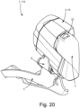
- FIG. 20 shows a front derailleur 110, wherein the electric power supply unit 2 is seated and clamped. Similar numbers are used for the same members or corresponding to those used for the rear derailleur 3.
- the displacement of the chain guide 5 has at least one displacement component in the direction of the bottom bracket spindle, so as to bring the transmission chain or belt into engagement with a toothed wheel or chain ring of the crankset.
- the component 10 having the seat 21 for removable attachment of the electric power supply unit 2 is the support body 4, and the geared motor 9 is, for example, also supported by the top body 4, but also in this case, different locations of the electric power supply unit 2 and of the geared motor are possible.
Landscapes
- Engineering & Computer Science (AREA)
- Mechanical Engineering (AREA)
- Chemical & Material Sciences (AREA)
- Combustion & Propulsion (AREA)
- Transportation (AREA)
- Battery Mounting, Suspending (AREA)
- Motorcycle And Bicycle Frame (AREA)
- Electric Propulsion And Braking For Vehicles (AREA)
- Steering Devices For Bicycles And Motorcycles (AREA)
- Axle Suspensions And Sidecars For Cycles (AREA)
Abstract
Description
- The present invention relates in general to a bicycle equipment provided with an electric power supply unit.
- Bicycle electric/electronic pieces of equipment which require an electric power supply unit, typically of the secondary cell battery type, comprise for example a derailleur associated with the bottom bracket spindle, a derailleur associated with the hub of the rear wheel, a suspension, a saddle setting adjuster, a lighting system, a satellite navigator, a training device, an anti-theft device, a cycle computer capable of providing information on the status of the bicycle, of the cyclist and/or of the route, a torque or power meter, a motor of a pedal assisted bicycle, a manual control device of another equipment, and others.
- In the present description and in the attached claims, under "equipment" a set of components mechanically coupled with each other and configured to be attached to the bicycle in a single location is meant to be understood. Thus, the equipment may comprise for example a derailleur or a manual control device for a derailleur attachable to the handlebars or in proximity thereto, but not the assembly of both.
- In the present description and in the attached claims, expression "electric/electronic" is used to indicate an electric device that may also include electronic components and/or a data processing system.
- The electric power supply unit is typically removably attached to the bicycle equipment, in order to allow recharge thereof from the mains (possibly through a recharge saddle) besides any possibility of recharging it on board of the bicycle and/or in order to allow replacement thereof in case of performance degradation.
- In the present description and in the attached claims, a mechanical connection between two members is called "removable" if it allows them to be detached without the aid of tools.
- The technical problem at the basis of the invention is to provide a bicycle equipment with an electric power supply unit which may be attached and detached in an easy, quick and reliable manner despite the conditions of dirt and humidity to which the equipment is subject; desirably the weight and cost associated with the elements intended for removable attachment of the electric power supply unit should be contained.
- In an aspect, the invention relates to an electrically powered bicycle equipment, comprising:
- an electric power supply unit comprising one or more secondary cells,
- a component having an attachment/detachment seat for removable attachment of the electric power supply unit,
the attachment/detachment seat and the electric power supply unit having matching electric contacts that establish electrical connection in the seated state of the electric power supply unit, and - at least one latch assembly for retaining the electric power supply unit in the seated state, comprising a slider having a head and a back opposed to the head,
- one of the electric power supply unit and the component having a sliding seat of the slider, the other one of the electric power supply unit and the component having a retaining seat of the head against a displacement at least in a first way of a retaining direction, in the seated state of the electric power supply unit and in the latched condition of the latch assembly,
- wherein the slider is slidable in the sliding seat between a fully advanced position wherein the head protrudes from the sliding seat in order to be able to insert in the retaining seat, and a fully retracted position wherein the head does not protrude from the sliding seat,
- wherein the sliding seat comprises a blind hole, the blind hole and the back of the slider having complementary shapes in a section transverse to the sliding direction, and the blind hole being sized to accommodate the back of the slider in a sliding manner,
- wherein the back of the slider has a closed-loop peripheral groove, and wherein a ring gasket is housed taut in the peripheral groove,
- wherein in at least one region of the back of the slider, the peripheral groove has two aligned sections and an intermediate section therebetween, the intermediate section being comparatively deeper than the two aligned sections,
- whereby in the fully advanced position of the slider, a portion of the gasket bridges the intermediate section between the two aligned sections, and while the slider moves back, the portion of the gasket is free to curve towards the bottom of the intermediate section of the peripheral groove.
- In the present description and in the attached claims, under "sliding" a type of clearance coupling wherein the force may not be transmitted by the coupling force alone is meant.
- In the present description and in the attached claims, term "intermediate" does not imply that the portion is central and equidistant from the aligned sections.
- The Applicant has recognised that the local deformation of the gasket towards the bottom of the peripheral groove, establishing a gap between the gasket and the inner wall of the blind hole of the sliding seat, counteracts the establishment of an overpressure in the blind hole itself, whereby the resistance offered by the sliding seat against the push of the slider in rearward direction (in order to open the latch and thus release the electric power supply unit or allow seating thereof) is not increased by the overpressure, thus requiring less physical effort with the finger. Furthermore, the gap acts as a vent for air from the blind hole during the push on the slider, favouring expulsion of dust particles, dirt and water possibly present in the proximity of the mouth of the blind hole of the sliding seat, hindering entry thereof in the blind hole of the seat where they could jam or in any case hinder the correct operation of the latch assembly: thus not only the gap is not detrimental for the hermetic sealing function, rather it enhances that function.
- The depth of the intermediate section may be continuously variable from a maximum depth value at its center to a depth value of the two aligned sections.
- The latch assembly may comprise elastic means urging the slider towards the advanced position, in particular at least one compression spring housed in the blind hole and acting by pushing on the back of the slider. In case said one or more compression springs is/are provided for, the problem of inlet of dirt and humidity in the blind hole is particularly felt.
- Said at least one region of the back of the slider may also comprise two regions of the back of the slider, in particular two opposed regions.
- The back of the slider may have, in cross-section, an oval shape.
- In the present description and in the attached claims, under "oval shape" a rounded and slightly elongate shape is meant to be understood. More specifically, under "oval" a closed plane line enclosing a convex plane region and provided in any point with a tangent straight line that is continually variable, for example an ellipse, is meant to be understood.
- When the back of the slider has an oval cross-section, said at least one region of the back of the slider is, for example, comprised in at least one longest side of the oval cross-section.
- The sliding seat may further comprise a guide channel contiguous to the blind hole, the guide channel having a sliding bottom for the slider, the bottom being formed on said one of the electric power supply unit and the component. The guide channel has a longitudinal direction extending along the sliding direction.
- In the present description and in the attached claims, under "contiguous", adjacent and adjoining is meant to be understood.
- The slider may have a control region sliding along the guide channel.
- The control region may have a finger resting surface, which may have the concavity towards the head of the slider.
- In the proximity of the end of the guide channel opposed to that contiguous to the blind hole, a crosspiece may be provided for, the head of the slider being in sliding and/or rolling coupling with the crosspiece. The crosspiece is effective to hold the slider on the bottom of the guide channel.
- In the present description and in the attached claims, under "crosspiece" a member extending orthogonally to the sliding direction and spaced from and parallel to the bottom of the channel is meant to be indicated.
- The crosspiece may be a non-pivotable pin, with sliding friction between the crosspiece and the head, or a pin pivotable about its ow longitudinal axis, with rolling friction between pin and head.
- The head of the slider may form a step with the control region of the slider, the riser of the step abutting against the crosspiece in the fully advanced position of the slider. The crosspiece then also plays the role of limiter of the slider and provides a tactile and acoustic feeling to the operator because the stop of the slider is determined by the sudden shock of the riser on the pin.
- The retaining seat formed in said other one of the electric power supply unit and the component may define an abutment or limiter surface configured to receive, in abutment and pushing relationship, a surface of the head facing away from said one of the electric power supply unit and the component. In this manner the latch assembly is effective to retain the electric power supply unit against removal from the component.
- The retaining seat may further define at least one second abutment surface configured to receive, in abutment and pushing relationship, another surface of the head, facing toward said one of the electric power supply unit and the component or facing laterally with respect to said one of the electric power supply unit and the component, for example the surface sliding on the bottom of the channel and/or a surface of the head not parallel to the bottom of the channel. In this manner, the retaining seat is effective to retain the electric power supply unit against movements also in other oriented directions, in particular against movements along the direction transverse to the guide channel.
- The attachment/detachment seat formed on the component may be configured to retain at least one region of the electric power supply unit, substantially opposed to a region involved by the latch assembly, against removal from the component at least in a second way of the retaining direction, opposed to the first way.
- Alternatively or additionally, at least one second latch assembly may be provided for in said region of the electric power supply unit substantially opposed to the region involved by the latch assembly.
- The attachment/detachment seat formed on the component may comprise at least one sliding guide of the electric power supply unit along the retaining direction, and/or at least one of the electric power supply unit and the attachment/detachment seat may comprise at least one pilot member.
- In the present description and in the attached claims, under "pilot member" a gradual thinning of a protrusion or a widening of a cavity wherein it has to be inserted is meant to be indicated.
- In the present description and in the attached claims, term "cavity" is broadly meant to encompass a through cavity and a blind cavity or recess.
- The retaining direction may be the vertical direction and the first way may be downwards in the condition wherein the bicycle equipment is mounted on the bicycle and with the bicycle in the condition of straight travel on level ground. In this manner, the electric power supply unit is held suspended by the latch assembly.
- The matching electric contacts may be provided for on paired surfaces of the electric power supply unit and of the component, extending substantially orthogonal to the retaining direction.
- The electric contacts of one and a same between the electric power supply unit and the component may be of the pogo pin type.
- In at least one of the electric power supply unit and the component, the ground electric contact may be more outcropping than the other electric contacts.
- The matching electric contacts may be arranged in a protrusion and a cavity having complementary shapes. For example, the pogo pin contacts may be arranged in a cavity so as not to protrude when the electric power supply unit is not seated.
- The protrusion may have a peripheral groove, a hermetic seal gasket extending in said peripheral groove.
- The bicycle equipment may be a derailleur comprising:
- a plurality of mutually movable components, comprising a support body configured to be attached to a bicycle frame, a chain guide, and a pair of connecting arms extended between the support body and the chain guide, and
- a geared motor controlling the mutual motion between chain guide and support body,
- wherein said component having the attachment/detachment seat is a preselected component of the mutually movable components.
- In the present description and in the attached claims, term "chain guide" is used to indicate the component which, overall, is moved with respect to the support body and to the connecting arms; in the case of a rear derailleur it may include a first member articulated in the articulated parallelogram, sometimes called "bottom body", and a second member movable therewith, sometimes called "rocker arm", while in the case of a front derailleur it typically comprises a single member, sometimes called "cage".
- In the present description and in the attached claims, under term "geared motor", a motor not coupled with any speed reducer is meant to be encompassed.
- The derailleur is, for example, a rear derailleur.
- In that case, the preselected component is, for example, a connecting arm, in particular the proximal connecting arm. In such a location, the electric power supply unit turns out to be particularly protected against shocks to which it is subject during the travel of the bicycle.
- Alternatively, the derailleur may be a front derailleur, the preselected component being for example the support body.
- The geared motor may be housed in a second component of the plurality of mutually movable components different from the preselected component, for example in the support body when the preselected component is a connecting arm, an electric connection being provided for, extended between the contacts of the attachment/detachment seat and the second component.
- Alternatively, the geared motor may be housed in the preselected component, for example geared motor and electric power supply unit may both be housed in the support body.
- The derailleur may also include a data processing system, controlling the geared motor and any other electric/electronic components of the derailleur. The data processing system may comprise electric components and/or discrete electronic components and/or a micro-controller, which may also integrate memory means. The data processing system may be borne for example on at least one printed circuit board or PCB. The derailleur may thus be electronic.
- Further features and advantages of the present invention will become clearer from the following detailed description of some preferred embodiments thereof, made with reference to the attached drawings, wherein:
-
FIG. 1 is a perspective view of a bicycle equipment provided with an electric power supply unit, -
FIG. 2 is a view according to another perspective of the bicycle equipment provided with an electric power supply unit ofFIG. 1 , -
FIG. 3 is an exploded view of the electric power supply unit and of the associated components of a latch assembly for holding the electric power supply unit to the bicycle equipment, -
FIGs. 4-7 show some steps during the movement for seating and locking the electric power supply unit on a component of the bicycle equipment ofFIG. 1 , in a perspective view, -
FIG. 8 is a cross-sectional partially cutaway view taken at the latch assembly, in the latched condition, -
FIG. 9 shows some members of the latch assembly in the latched condition, in a perspective view, -
FIG. 10 shows a cross-section across the latch assembly, in the latched condition, -
FIG. 11-13 are views corresponding toFIGs. 8-10 , wherein the latch assembly is in the released condition, -
FIG. 14-15 are views corresponding toFIGs. 10 and13 , with a modified latch assembly, -
FIGs. 16-19 show some details relating to the electrical connection of the electric power supply unit to the bicycle equipment, and -
FIG. 20 is a perspective view of another bicycle equipment, with the electric power supply unit attached thereto. - In
FIGs. 1-2 an illustrative bicycle equipment 1 is shown, provided with an electricpower supply unit 2. - In the case shown, the bicycle equipment 1 is a rear derailleur 3 comprising a
support body 4 configured to be attached to a bicycle frame, achain guide 5 and a pair of connectingarms 6, 7 extended between thesupport body 4 and thechain guide 5, forming a plurality of mutually movable components and in particular an articulated parallelogram. The pair of connecting arms comprises a proximal connectingarm 6 and a distal connecting arm 7. In the present description and in the attached claims, adjectives such as "proximal" and "distal" refer to the mounted condition of the derailleur on the bicycle. In particular, "proximal" is used to indicate closer to the frame and adjective "distal" is used to indicate farther from the frame. - The derailleur 3 comprises a geared
motor 9. The gearedmotor 9 may be purely electric or electronic, when the derailleur 3 also includes a data processing system controlling the geared motor and any other electric/electronic components of the derailleur 3, for example comprising one or more components borne by one or more printed circuit boards or PCBs. As mentioned above, the geared motor may also comprise a motor not coupled with any speed reducer. - The geared motor controls the mutual motion between
chain guide 5 andsupport body 4, in particular determines the aperture and closure of the articulated parallelogram, and therefore a displacement of thechain guide 5 having at least one displacement component in the direction of the axis of the group of toothed wheels associated with the hub of the rear wheel or "sprocket assembly", so as to bring the transmission chain or belt into engagement with a predetermined toothed wheel or sprocket of the sprocket assembly. The gearedmotor 9 is for example housed in thesupport body 4 and controls the rotation of one of the connectingarms 6, 7 (in the case shown, the proximal connecting arm 6) about a pivotal axis thereof to thesupport body 4. The gearedmotor 9 is shown directly coupled with the proximal connectingarm 6, but this is not strictly necessary. For example, thesupport body 4 may be attached to the frame through a connecting device so-called "articulated joint" 8. - With reference also to
FIG. 3 , the electricpower supply unit 2 comprises one or moresecondary cells 10 and a hermetic case housing said one or moresecondary cells 10, formed for example by acontainer 11 and acover 12. The electricpower supply unit 2 may also include at least one printed circuit board orPCB 13 bearing electronic components controlling the electricpower supply unit 2, housed in the hermetic case. The electricpower supply unit 2 may therefore also be a so-called smart battery. - With reference also to
FIGs. 4-7 , the electricpower supply unit 2 is removably attached to the derailleur 3, and it is shown in the detached condition inFIG. 4 . To this end, a component of the derailleur 3, the proximal connectingarm 6 in the case shown, has an attachment/detachment seat 21 for the electricpower supply unit 2. The component having theseat 21 for the electricpower supply unit 2 is not necessarily the proximal connectingarm 6 and therefore hereinafter the component provided with theseat 21 will be referred to ascomponent 20. - At least one
latch assembly 22 for holding the electricpower supply unit 2 in the seated state, on thecomponent 20, is provided for, wherein the electricpower supply unit 2 is arranged in the attachment/detachment seat 21. When the electricpower supply unit 2 is seated and thelatch assembly 22 is in the latched condition, the electricpower supply unit 2 is firmly held on the derailleur 3 despite the vibrations and shocks to which it is subject during the bicycle travel. - With reference also to
FIGs. 8-10 , thelatch assembly 22 first comprises aslider 23 having ahead 24 and a back 25 opposed to thehead 24. - In the case shown, the electric
power supply unit 2 has a slidingseat 26 of theslider 23 along a sliding direction X (FIG. 8 ), and thecomponent 20 has a retainingseat 27 of thehead 24 against a displacement at least in a first way of a retaining direction Y (cf. the positive direction of the axis Y emphasised inFIG. 8 ), in the seated state of the electricpower supply unit 2 and in the latched condition of thelatch assembly 22. - For example, the retaining
seat 27 is formed by a cavity that defines an abutment surface orlimiter 29 configured to receive, in abutment and pushing relationship, afirst surface 30 of thehead 24. Thesurfaces - The
slider 23 slides in the slidingseat 26 between a fully advanced position (FIGs. 4 ,7 ,8 ) wherein thehead 24 protrudes from the slidingseat 26 in order to be able to insert - in said seated state of the electricpower supply unit 2 on the component 20 - in the retainingseat 27, and a fully retracted position (FIGs. 5 ,6 ,11 ) wherein thehead 24 does not protrude from the sliding seat 26 - allowing the seating of the electricpower supply unit 2 in thecomponent 20 or vice versa the extraction thereof from the attachment/detachment seat 21 for removal from thecomponent 20. - The sliding
seat 26 comprises ablind hole 31. Theblind hole 31 and theback 25 of theslider 23 have complementary shapes in a section transverse to the sliding direction X. Theblind hole 31 is sized to receive theback 25 of theslider 23 in a sliding manner. - In the case shown, the
latch assembly 22 comprises a plurality of side-by-side compression springs 32, housed in theblind hole 31 and acting by pushing on theback 25 of theslider 23, for urging theslider 23 towards the advanced position. - In the case shown, the sliding
seat 26 further comprises aguide channel 33 contiguous to theblind hole 31. The bottom 34 of theguide channel 33, that provides a sliding surface for theslider 23, is formed on the electricpower supply unit 2. Theguide channel 33 is open outwards with respect to the electricpower supply unit 2. The guide channel has a longitudinal direction extended along the sliding direction X. - The
first surface 30 of thehead 24 is opposed to asecond surface 35 of thehead 24, that is slidingly coupled on the bottom 34 of theguide channel 33. - The
slider 23 has, in the case shown, acontrol region 36, sliding along theguide channel 33. Thecontrol region 36 may have, as shown, afinger resting surface 37 that has the concavity towards thehead 24 of theslider 23. - The
control region 37 may have acavity 38 open towards the bottom 34 of theguide channel 33, for reasons of moulding and lightening. - In the proximity of the end of the
guide channel 33 opposed to the one contiguous to the blind hole 31 (or head end) acrosspiece 39 is provided for, in the case shown. Thecrosspiece 39 extends in a transverse direction Z (FIG. 8 ) with respect to the sliding direction X, and is parallel to the bottom 34 of theguide channel 33, spaced therefrom. Thecrosspiece 39 is effective to hold thehead 24 of theslider 23 on the bottom 34 of theguide channel 33. For example, thehead 24 and in particular itsfirst surface 30 may be in sliding fit with thecrosspiece 39. - In the case shown, the
crosspiece 39 is formed by a pin. The friction between the crosspiece 39 and thehead 24 is sliding friction. Thecrosspiece 39 may also be formed by a pin pivotable about its own longitudinal axis, so that it turns out to be in rolling coupling with thefirst surface 30 of thehead 24; in this manner the friction between the crosspiece 39 and thehead 24 is rolling friction. - The
head 24 of theslider 23 forms, in the case shown, astep 40 with thecontrol region 36 of theslider 23, theriser 41 of the step abutting against thecrosspiece 39 in the fully advanced position of theslider 23. Thecrosspiece 39 thus also plays the role of limiter of theslider 23 and provides a tactile and acoustic feeling to the operator because the stop of theslider 23 is determined by the sudden shock of theriser 41 on thecrosspiece 39. - It is understood that in order to release the
latch assembly 22, theslider 23 has to be pushed in the direction of the arrow shown inFIGs. 5 and6 , for example acting on thefinger resting surface 37 of thecontrol region 36. That pushing action has to overcome the resistance offered by the slidingseat 26, caused by the compression springs 32 if present, and in any case by the friction at play between the sliding and/or rolling coupling parts mentioned above, as well as possibly by the weight of theslider 23 itself in the case in which the sliding direction has a vertically upwards component. - The Applicant has recognized that the
blind hole 31, if on the one side it protects theslider 23 and any compression springs 32 better than a through hole, is subject to the entry of dirt and humidity that may have as a consequence the jamming of theslider 23 and damaging or rusting of any compression springs 32. Furthermore, during the push of theslider 23, air is compressed by theslider 23 inside theblind hole 31, so that an overpressure establishes in theblind hole 31, tending to increase the resistance offered by the slidingseat 26, what not only increases the physical effort by the user, but also entails the risk of breaking theslider 23 or the need to make it stronger and heavier. - To the end, among others, of reducing or totally eliminating the drawbacks emphasised above, the
latch assembly 22 may be configured as described hereinafter. - The
back 25 of theslider 23 has a closed-loopperipheral groove 50 or peripheral throat (FIG. 3 ) (namely that runs all around the outer surface of the back 25). Aring gasket 51, for example an O-ring, is housed in theperipheral groove 50. - The
groove 50 does not have a constant depth along its extension, as evident inFIGs. 10 and13 . In detail, in aregion 52 of theback 25 of theslider 23, thegroove 50 has two alignedshallow portions deeper portion 55 intermediate therebetween. The depth of theportion 55 may be continually variable from a maximum depth value P2 at the centre to the depth value P1 of the two alignedsections portion 55 is formed by a recess in thegroove 50 substantially rounded and symmetric (considered in the cross-section of the slider 23), but this is not strictly necessary. - In the case shown, the back 25 of the
slider 23, as well as the inner wall of theblind hole 31 wherein it slides, has, in cross-section, an oval and in particular elliptical shape. In the case shown, theregion 52 is comprised in a longest side of the oval/elliptical section, but this is not necessary. The shape of theslider 23 may also be polygonal (for example square) with rounded edges or even substantially circular. - Furthermore, in the case shown there is an analogous confirmation of the
peripheral groove 50 in anotherregion 56 of theback 25 of theslider 23, but this is not necessary, as manifest fromFIGs. 14, 15 . Theregion 56 is opposed to theregion 52, but this is not necessary. - In both cases shown, it is noted that the bottom of the
peripheral groove 50 defines a concave plane figure in the plane of the drawing, transversal to the sliding direction X. In the present description and in the attached claims, under "concave plane figure" it is meant that at least two points of the figure are ends of a segment that is not entirely contained inside the figure. - As shown in
FIGs. 9 and 10 , in the fully advanced position of theslider 23, thegasket 51, mounted with adequate tension in theperipheral groove 50, is only subject to the longitudinal tensile stress. Aportion 57 thereof bridges theintermediate section 55 of theperipheral groove 50 between the two alignedsections gasket 51 contacts the inner wall of theblind hole 31, ensuring hermetic sealing. - While the
slider 23 moves back, theportion 57 of thegasket 51, subject to the overpressure that is established in theblind hole 31 due to the increase in the volume occupied by theslider 23, is free to curve toward the bottom of theintermediate section 55 of theperipheral groove 50, counteracting the establishment of the overpressure itself, because a gap establishes between thegasket 51 and the inner wall of theblind hole 31. - The
gap 58 in the condition of maximum deformation of thegasket 51 is manifest inFIGs. 11-13 that represent the fully retracted position of theslider 23. - As a consequence, the resistance offered by the sliding
seat 26 against the pushing of theslider 23 towards the backward position (in order to release thelatch assembly 22 and therefore set the electricpower supply unit 2 free, or allow its seating on the component 20) is not increased by the overpressure, thus requiring less physical effort with the finger. - In addition, during the push on the
slider 23 in the blind hole 31 (towards the fully retracted position) said gap acts as a vent for air, favouring the expulsion of particles of dust, dirt and water that may be present in the vicinity of the mouth of theblind hole 31, hindering their entry into the blind bottom 31 itself. By avoiding that dust and dirt may jam the latch assembly 22 -in particular when there are the compression springs 32- or in any case hinder its proper functioning, the sealing function of thegasket 51 is in fact enhanced. - As mentioned, the retaining
seat 27 of thehead 24, formed in thecomponent 20, is effective - thanks to its abutment surface or limiter 29 - to retain the electricpower supply unit 2, through itsfirst surface 30, against a displacement in the first way of the retaining direction Y (cf. the positive direction of axis Y shown inFIG. 8 ), in the seated state of the electricpower supply unit 2 and in the latched condition of thelatch assembly 22. - The retaining
seat 27 may be configured to also define one or more abutment surfaces or limiters (not shown), configured to receive, in an abutment and pushing relationship, thesecond surface 35 of thehead 24, facing toward the electricpower supply unit 2 and thecomponent 20 and sliding on the bottom 34 of theguide channel 33, and/or side surfaces 59, 60 of thehead 24, so as to retain the electricpower supply unit 2 against movements also in other oriented directions. In this manner thelatch assembly 22 may be even more effective to firmly hold the electricpower supply unit 2 on thecomponent 20. - The retaining
seat 27 may be configured to also define an abutment surface or limiter (not shown) configured to receive, in abutment and pushing relationship, thefront surface 61 of thehead 24, so as to prevent the exit of theslider 23 from theblind hole 31 in case of breaking of thecrosspiece 39 while the battery power supply unit is seated. Thefront surface 61 may be slanted with respect to the insertion direction X, as shown, the slanting acting as a pilot during the seating of thehead 24 in the retainingseat 27. - Alternatively, the retaining
seat 27 may be oversized with respect to thehead 24 along one or more of the axes X, Z, or of the negative direction of axis Y, so as to allow insertion thereof without relative sliding. - Turning back to
FIGs. 1-2 , in the case shown, the region 71 (FIG. 3 ) of the electricpower supply unit 2 involved by thelatch assembly 22 is intended to be the bottom one in the condition wherein the derailleur 3 is mounted on the bicycle and with the bicycle in the condition of straight travel on level ground, so that the electricpower supply unit 2 is held suspended by thelatch assembly 22. - In its opposed, or at least substantially opposed, region 72 (
FIG. 3 ) the electricpower supply unit 2 is supported (in case of overturning or nearly overturning of the bicycle) and held by the attachment/detachment seat 21. - In the case shown, in particular, the attachment/
detachment seat 21 is configured to retain saidopposed region 72 of the electricpower supply unit 2 against removal from thecomponent 20 in the opposed direction of the retaining direction (axis Y), upwards in said condition of straight travel on level ground of the bicycle and inFIG. 12 , through abracket 73. - Either one of the electric
power supply unit 2 and the attachment/detachment seat 21 may comprise a cavity and/or a protrusion having slanted pilot surfaces (not shown), to guide the correct seating of the electricpower supply unit 2 in thecomponent 20, as shown. There may also be more pilot members. - The attachment/
detachment seat 21 shown has one or more sliding guide(s) 76 extended along the retaining direction Y and conformed so as to retain the electricpower supply unit 2 against removal in sliding direction X and in transverse direction Z, for example through one or more undercut groove(s) 77 for accommodating a respective lug(s) 78 of the electricpower supply unit 2. In the present description and in the attached claims, under "undercut" a recessed surface inaccessible when using a straight tool is meant to be indicated. - The sliding
seat 76 is, however, not essential. - The attachment/
detachment seat 21 may be shaped in a manner even appreciably different from what has been shown, and may support and retain the electricpower supply unit 2 in a different manner and/or not in all the above mentioned directions. - Alternatively or additionally, a latch assembly analogous to the
latch assembly 22 may be provided for at saidregion 72 of the electricpower supply unit 2 substantially opposed to theregion 71 involved by thelatch assembly 22, and/or at other regions of the electricpower supply unit 2. - The electric
power supply unit 2 shown has substantially the shape of a rectangular parallelepiped, but the shape of the electricpower supply unit 2 may also deviate appreciably from that shown. For example the electricpower supply unit 2 may have the shape of an oblique parallelepiped or may comprise one or more concave or convex faces (or regions thereof). - The attachment/
detachment seat 21 and the electricpower supply unit 2 have matchingelectric contacts 80, 81 (FIGs. 4, 5 ,16, 18 ) that establish the electric connection in the seated state of the electricpower supply unit 2. In the case shown, four pairs of matchingelectric contacts secondary cells 10 of the electricpower supply unit 2 and are provided to lead the power supply voltage from the electricpower supply unit 2 to the user(s) provided for in thecomponent 20, for example to the gearedmotor 9, and possibly for recharging the secondary cells when the electricpower supply unit 2 is not seated. The other two pairs of matchingelectric contacts power supply unit 2, when it is of the smart battery type, provided with electronic components borne for example by thePCB 13. From the electricpower supply unit 2 to the equipment 1, for example the residual charge, the number of recharge cycles made, etc., may be communicated. From the equipment 1 to the electricpower supply unit 2, for example a serial number thereof, a firmware update program, a request to communicate said data, etc., may be communicated. - However, a different number of pairs of matching
electric contacts - In the case shown, the matching
electric contacts bracket 73 of the attachment/detachment seat 21 and in the surface or region of the electricpower supply unit 2 paired thereto, extended substantially orthogonal to the retaining direction Y, that corresponds to the seating direction of the electricpower supply unit 2. However, the matchingelectric contacts detachment seat 21 and of the electricpower supply unit 2 that enter into mechanical contact when the electricpower supply unit 2 is seated, in particular when the seating movement of the electricpower supply unit 2 is a roto-translatory one. - With reference also to
FIGs. 16-19 , regardless of where they are located, the matchingelectric contacts protrusion 83 and a cavity orrecess 84 of complementary shapes. In the case shown theprotrusion 83 is made in the electricpower supply unit 2 and thecavity 84 is made in thecomponent 20, but they might be reversed. - The
protrusion 83 may have aperipheral groove 85, a hermetic seal gasket 86 (FIG. 3 ) extending in theperipheral groove 85. - Arranging the protruding or "male" contacts in the cavity or
recess 84, they are more protected also when the electricpower supply unit 2 is not seated. - The "male" electric contacts, of the
component 20 in the case shown by way of an example, may be of the pogo pin type. - A pogo pin - see the pogo-
pins 90 of which a section is schematically shown inFIG. 17 - comprises aplunger 91 sliding in ablind barrel 92; theplunger 91 is forced in the position protruding from thebarrel 92, outwards, by ahelical spring 93. The pogo pin contacts are for example gathered on a printed circuit board orPCB 94 and thebarrels 92 extend through parallel throughholes 95 of an electrically insulatingsupport 96 that may also serve as a hermetic seal. Alternatively to thePCB 94, the pogo-pin may be directly tinned to the respective electrical conductors. - The matching contact 100 (
FIG. 19 ) of a pogo pin comprises a plane orconcave plate 101 contacting theplunger 91 of thepogo pin 90. The matchingcontacts 100 are for example gathered on a printed circuit board orPCB 102 and extend through parallel throughholes 103 of an electrically insulatingsupport 104 that may also serve as a hermetic seal. Alternatively, theplate 101 may be directly embodied by a plated pad on thePCB 102. - These types of matching
contacts - The ground electric contact 105 ("female" or matching
contact 100 of the pogo pin 90) may be more outcropping than the other electric contacts of the electric power supply unit 2 (in the illustrative case shown). In this manner, it is the first to enter into mechanical and electric contact with therespective pogo pin 97 during the movement of seating of the electricpower supply unit 2, so as to protect the electronics by stabilizing the reference voltage level before the establishment of the remaining electrical connections. - Although the
latch assembly 22 is shown as having theslider 23 supported by the electricpower supply unit 2 and interacting with the retainingseat 27 provided on thecomponent 20, those skilled in the art will understand, in the light of the previous description, that a dual configuration is possible, wherein thelatch assembly 22 has theslider 23 supported by thecomponent 20, and the retainingseat 27 is provided on the electricpower supply unit 2. - The sliding
seat 26 need not necessarily comprise aguide channel 33, which may be totally absent or replaced for example by a guide slit made in the lateral wall of theblind hole 31. Thecontrol region 36 of theslider 23 might in that case be replaced by a grip member sliding in the slit and protruding therefrom. - In any case, alternatively to the
control region 36 provided with thefinger resting surface 37, a different member may be provided for gripping or engaging theslider 23 and pushing it - or puling it - to bring thelatch assembly 22 from the latched condition to the released condition. - The
compression spring 32 might be absent or be replaced by other elastic means for urging theslider 23 towards the advanced position. - Those skilled in the art will understand that the derailleur 3 may have a shape even considerably different from that shown and/or additional components not shown for the sake of simplicity.
- In the case shown, as mentioned the geared
motor 9 is housed in thesupport body 4, differently from the attachment/detachment seat 21 for the electricpower supply unit 2 that is made in the proximal connectingarm 6. In this case, there is an electric connection extended between the contacts of the attachment/detachment seat 21 and thesupport body 4. The gearedmotor 9 might be housed in still another component of the derailleur 3 or in general of the bicycle equipment 1, different from thecomponent 20 preselected for the attachment/detachment seat 21. - Alternatively, the geared
motor 9 may be housed in the or supported by thesame component 20 preselected for the attachment/detachment seat 21, for example gearedmotor 9 and electric power supply unit may both be housed in thesupport body 4 of a derailleur 3. - The secondary cells of the electric
power supply unit 2 may be recharged while the electricpower supply unit 2 is on board of the bicycle, by providing for suitable recharge connectors, and/or the electricpower supply unit 2 may be recharged in a recharge cradle after having been detached from the equipment 1, possibly exploiting the sameelectric contacts 81. - Although it has been described in the context of a rear derailleur 3, the invention disclosed herein, including all variants and generalisations thereof, also applies to a front derailleur.
- Merely by way of an example,
FIG. 20 shows a front derailleur 110, wherein the electricpower supply unit 2 is seated and clamped. Similar numbers are used for the same members or corresponding to those used for the rear derailleur 3. - In the case of the front derailleur 110, the displacement of the
chain guide 5 has at least one displacement component in the direction of the bottom bracket spindle, so as to bring the transmission chain or belt into engagement with a toothed wheel or chain ring of the crankset. - In the case of the front derailleur 110 shown, the
component 10 having theseat 21 for removable attachment of the electricpower supply unit 2 is thesupport body 4, and the gearedmotor 9 is, for example, also supported by thetop body 4, but also in this case, different locations of the electricpower supply unit 2 and of the geared motor are possible. - Furthermore, the invention disclosed herein also applies to a different electrically powered bicycle equipment, for example one of those listed in the introductory part.
- The various embodiments, variants and/or possibilities of each component or group of components that have been described are to be meant as combinable with each other in any manner, unless they are mutually incompatible.
- The above is a description of various embodiments of inventive aspects, and further changes can be made without departing from the scope of the present invention. The shape and/or size and/or location and/or orientation of the various components and/or the succession of the various steps can be changed. The functions of an element or module can be carried out by two or more components or modules, and vice-versa. Components shown directly connected to or contacting each other can have intermediate structures arranged in between them. Steps shown directly following each other can have intermediate steps carried out between them. The details shown in a figure and/or described with reference to a figure or to an embodiment can apply in other figures or embodiments. Not all of the details shown in a figure or described in a same context must necessarily be present in a same embodiment. Features or aspects that turn out to be innovative with respect to the prior art, alone or in combination with other features, should be deemed to be described per se, irrespective of what is explicitly described as innovative.
Claims (15)
- Electrically powered bicycle equipment (1), comprising:- an electric power supply unit (2) comprising one or more secondary cells (10),- a component (20) having an attachment/detachment seat (21) for removable attachment of the electric power supply unit (2),
the attachment/detachment seat (21) and the electric power supply unit (2) having matching electric contacts (80, 81) that establish electrical connection in the seated state of the electric power supply unit (2), and- at least one latch assembly (22) for retaining the electric power supply unit (2) in the seated state, comprising a slider (23) having a head (24) and a back (25) opposed to the head (24),one of the electric power supply unit (2) and the component (20) having a sliding seat (26) of the slider (23), the other one of the electric power supply unit (2) and the component (20) having a retaining seat (27) of the head (24) against a displacement at least in a first way of a retaining direction (Y), in the seated state of the electric power supply unit (2) and in the latched condition of the latch assembly (22),wherein the slider (23) is slidable in the sliding seat (26) between a fully advanced position wherein the head (24) protrudes from the sliding seat (26) in order to be able to insert in the retaining seat (27), and a fully retracted position wherein the head (24) does not protrude from the sliding seat (26),wherein the sliding seat (26) comprises a blind hole (31), the blind hole (31) and the back (25) of the slider (23) having complementary shapes in a section transverse to the sliding direction (X), and the blind hole (31) being sized to accommodate the back (25) of the slider (23) in a sliding manner,wherein the back (25) of the slider (23) has a closed-loop peripheral groove (50), and wherein a ring gasket (51) is housed taut in the peripheral groove (50),wherein in at least one region (52, 56) of the back (25) of the slider (23), the peripheral groove (50) has two aligned sections (53, 54) and an intermediate section (55) therebetween, the intermediate section (55) being comparatively deeper than the two aligned sections (53, 54,whereby in the fully advanced position of the slider (23), a portion (57) of the gasket (51) bridges the intermediate section (55) between the two aligned sections (53, 54), and while the slider (23) moves back, the portion (57) of the gasket (51) is free to curve towards the bottom of the intermediate section (55) of the peripheral groove (50). - Bicycle equipment (1) according to claim 1, wherein the latch assembly (22) comprises elastic means (32) urging the slider (23) towards the advanced position, preferably at least one compression spring (32) housed in the blind hole (31) and acting by pushing on the back (25) of the slider (23).
- Bicycle equipment (1) according to any of the previous claims, wherein said at least one region (52, 56) of the back (25) of the slider (23) comprises two regions (52, 56) of the back (25) of the slider (23), preferably two opposed regions (52, 56).
- Bicycle equipment (1) according to any of the previous claims, wherein the back (25) of the slider (23) has, in cross-section, an oval shape, and said at least one region (52, 56) of the back (25) of the slider (23) is preferably comprised in at least one longest side of the oval section.
- Bicycle equipment (1) according to any of the previous claims, wherein the sliding seat (26) further comprises a guide channel (33) contiguous to the blind hole (31), the guide channel (33) having a sliding bottom (34) for the slider (23), the bottom (34) being formed on said one of the electric power supply unit (2) and the component (20), and wherein preferably the slider (23) has a control region (36) sliding along the guide channel (33).
- Bicycle equipment (1) according to claim 5, wherein the control region (36) has a finger resting surface (37), having the concavity towards the head (24) of the slider (23).
- Bicycle equipment (1) according to claim 5 or 6, wherein in the proximity of the end of the guide channel (33) opposed to that contiguous to the blind hole (31), a crosspiece (39) is provided for, the head (24) of the slider (23) being in sliding and/or rolling coupling with the crosspiece (39), wherein preferably the crosspiece (39) is a pin, possibly pivotable about its own longitudinal axis.
- Bicycle equipment (1) according to any of claims 5-7, wherein the head (24) of the slider (23) forms a step (40) with the control region (36) of the slider (23), the riser (41) of the step (40) abutting against the crosspiece (39) in the fully advanced position of the slider (23).
- Bicycle equipment (1) according to any of the previous claims, wherein the retaining seat (27) formed in said other one of the electric power supply unit (2) and the component (20) defines an abutment surface (29) configured to receive, in abutment and pushing relationship, a surface (30) of the head (24) facing away from said one of the electric power supply unit (2) and the component (20).
- Bicycle equipment (1) according to any of the previous claims, wherein the attachment/detachment seat (21) formed on the component (20) is configured to retain at least one region (72) of the electric power supply unit (2), substantially opposed to a region (71) involved by the latch assembly (22), against removal from the component (20) at least in a second way of the retaining direction (Y), contrary to the first way.
- Bicycle equipment (1) according to any of the previous claims, wherein the attachment/detachment seat (21) formed on the component (20) comprises at least one sliding guide (76) of the electric power supply unit (2) along the retaining direction (Y), and/or at least one of the electric power supply unit (2) and the attachment/detachment seat (21) comprises at least one pilot member.
- Bicycle equipment (1) according to any of the previous claims, wherein the retaining direction (Y) is the vertical direction, and the first way is downwards in the condition wherein the bicycle equipment (1) is mounted on the bicycle and with the bicycle in the condition of straight travel on level ground.
- Bicycle equipment (1) according to any of the previous claims, wherein the electric contacts (80, 81) of one and a same between the electric power supply unit (2) and the component (20) are of the pogo pin type and/or wherein in at least one of the electric power supply unit (2) and the component (20), the ground electric contact (97, 105) is more outcropping than the other electric contacts.
- Bicycle equipment (1) according to any of the previous claims, wherein the bicycle equipment (1) is a derailleur (3, 110), comprising:a plurality of mutually movable components (4, 5, 6, 7), comprising a support body (4) configured to be attached to a bicycle frame, a chain guide (5), and a pair of connecting arms (6, 7) extended between the support body (4) and the chain guide (5), anda geared motor controlling the mutual motion between chain guide (5) and support body (4),wherein said component (20) having the attachment/detachment seat (21) is a preselected component (20) of the mutually movable components (4, 5, 6, 7).
- Bicycle equipment (1) according to claim 14, wherein the derailleur (3, 110) is a rear derailleur and the component (20) is a connecting arm, in particular the proximal connecting arm (6), or wherein the derailleur (3, 110) is a front derailleur and the component (20) is the support body (4).
Applications Claiming Priority (1)
| Application Number | Priority Date | Filing Date | Title |
|---|---|---|---|
| IT102021000024725A IT202100024725A1 (en) | 2021-09-28 | 2021-09-28 | BICYCLE EQUIPMENT EQUIPPED WITH ELECTRIC POWER SUPPLY UNIT |
Publications (2)
| Publication Number | Publication Date |
|---|---|
| EP4155183A1 true EP4155183A1 (en) | 2023-03-29 |
| EP4155183B1 EP4155183B1 (en) | 2024-05-01 |
Family
ID=78771075
Family Applications (1)
| Application Number | Title | Priority Date | Filing Date |
|---|---|---|---|
| EP22197992.5A Active EP4155183B1 (en) | 2021-09-28 | 2022-09-27 | Bicycle equipment provided with an electric power supply unit |
Country Status (5)
| Country | Link |
|---|---|
| US (1) | US11919594B2 (en) |
| EP (1) | EP4155183B1 (en) |
| CN (1) | CN115871830A (en) |
| IT (1) | IT202100024725A1 (en) |
| TW (1) | TW202323126A (en) |
Families Citing this family (6)
| Publication number | Priority date | Publication date | Assignee | Title |
|---|---|---|---|---|
| US9394030B2 (en) * | 2012-09-27 | 2016-07-19 | Sram, Llc | Rear derailleur |
| IT202100024800A1 (en) | 2021-09-28 | 2023-03-28 | Campagnolo Srl | ELECTRONIC BICYCLE EQUIPMENT |
| DE102022204093A1 (en) | 2022-04-27 | 2023-11-02 | Shimano Inc. | DERAILLEUR FOR A HUMAN POWERED VEHICLE |
| US12116085B1 (en) | 2023-10-20 | 2024-10-15 | Shimano Inc. | Component for human-powered vehicle |
| EP4725817A1 (en) * | 2024-10-08 | 2026-04-15 | Campagnolo S.r.l. | Bicycle electric device |
| US12617492B1 (en) * | 2025-02-26 | 2026-05-05 | Tien Hsin Industries Co., Ltd. | Electronic derailleur |
Citations (2)
| Publication number | Priority date | Publication date | Assignee | Title |
|---|---|---|---|---|
| US5881823A (en) * | 1995-06-14 | 1999-03-16 | Robert Bosch Gmbh | Hand machine tool with battery operated drive motor, and battery unit for the same |
| US10981625B2 (en) * | 2017-10-02 | 2021-04-20 | Sram, Llc | Bicycle rear derailleur |
Family Cites Families (44)
| Publication number | Priority date | Publication date | Assignee | Title |
|---|---|---|---|---|
| JP4065286B2 (en) * | 2005-08-09 | 2008-03-19 | 株式会社シマノ | Bicycle electric derailleur |
| US9394030B2 (en) * | 2012-09-27 | 2016-07-19 | Sram, Llc | Rear derailleur |
| US9890838B2 (en) * | 2012-10-18 | 2018-02-13 | Sram, Llc | Front gear changer |
| US8888620B2 (en) * | 2012-12-05 | 2014-11-18 | Shimano Inc. | Front derailleur |
| JP2014213705A (en) * | 2013-04-25 | 2014-11-17 | 株式会社シマノ | Derailleur for bicycle |
| US9676444B2 (en) * | 2013-10-23 | 2017-06-13 | Sram, Llc | Electromechanical rear derailleur |
| US9555857B2 (en) * | 2014-06-04 | 2017-01-31 | Shimano Inc. | Bicycle front derailleur |
| EP3002185B1 (en) | 2014-10-03 | 2017-11-15 | Campagnolo S.R.L. | Bicycle control device |
| US20170101155A1 (en) * | 2015-10-09 | 2017-04-13 | Shimano Inc. | Bicycle electrical component |
| US9963197B2 (en) * | 2015-10-26 | 2018-05-08 | Shimano Inc. | Electric bicycle rear derailleur |
| US10370060B2 (en) * | 2015-10-30 | 2019-08-06 | Shimano Inc. | Bicycle electrical component assembly |
| US9944350B2 (en) * | 2016-01-11 | 2018-04-17 | Sram, Llc | Chain guide sensor and methods of controling a bicycle |
| IT201600069087A1 (en) * | 2016-07-04 | 2018-01-04 | Campagnolo Srl | Front electric bicycle derailleur |
| IT201600081324A1 (en) | 2016-08-02 | 2018-02-02 | Campagnolo Srl | Bicycle control device |
| US10875601B2 (en) * | 2017-02-10 | 2020-12-29 | Sram, Llc | Bicycle derailleur and connection |
| IT201700018702A1 (en) * | 2017-02-20 | 2018-08-20 | Campagnolo Srl | Rear electric derailleur of bicycle |
| US10953950B2 (en) * | 2017-03-08 | 2021-03-23 | Shimano Inc. | Bicycle electric device and bicycle wireless control system |
| US10843757B2 (en) * | 2017-03-08 | 2020-11-24 | Shimano Inc. | Bicycle electric telescopic apparatus, bicycle power supply system, and bicycle electric component system |
| US10793222B1 (en) * | 2017-03-21 | 2020-10-06 | Jonathan K. Harris | Bicycle derailleur having upper and lower alignment assemblies |
| US11199240B2 (en) * | 2017-03-27 | 2021-12-14 | Sram, Llc | Fluid damper for a bicycle component |
| IT201700038213A1 (en) | 2017-04-06 | 2018-10-06 | Campagnolo Srl | Manual control device for bicycle and electronic bicycle system that includes it |
| US11560199B2 (en) * | 2018-12-12 | 2023-01-24 | Brandon Rodgers | Gearshifting system comprising a linear actuator |
| US10894574B2 (en) * | 2017-10-02 | 2021-01-19 | Sram, Llc | Bicycle rear derailleur |
| DE102017010348A1 (en) * | 2017-11-09 | 2019-05-09 | Sram Deutschland Gmbh | Electromechanical rear derailleur |
| TWM562815U (en) * | 2018-04-03 | 2018-07-01 | 彥豪金屬工業股份有限公司 | Derailleur assembly |
| TWM562816U (en) * | 2018-04-03 | 2018-07-01 | 彥豪金屬工業股份有限公司 | Derailleur assembly |
| US11661139B2 (en) * | 2018-04-11 | 2023-05-30 | Sram, Llc | Electromechanical control device and methods for electromechanical control of a bicycle |
| DE102018207493A1 (en) * | 2018-05-15 | 2019-11-21 | Sram Deutschland Gmbh | A bicycle adjusting device and method of controlling or adjusting such adjusting devices |
| TWI687345B (en) * | 2018-11-16 | 2020-03-11 | 彥豪金屬工業股份有限公司 | Bicycle front derailleur |
| US11518472B2 (en) * | 2019-02-15 | 2022-12-06 | Sram, Llc | Bicycle control system |
| TWI723397B (en) * | 2019-03-19 | 2021-04-01 | 彥豪金屬工業股份有限公司 | Bicycle rear derailleur |
| DE102020000827A1 (en) * | 2019-04-25 | 2020-10-29 | Sram Deutschland Gmbh | Electromechanical switching mechanism for coaxial assembly |
| US11840315B2 (en) * | 2019-05-02 | 2023-12-12 | Sram, Llc | Gear changer adjustment and device |
| US11192607B2 (en) * | 2019-05-30 | 2021-12-07 | Shimano Inc. | Electric front derailleur |
| US11535339B2 (en) * | 2019-08-30 | 2022-12-27 | Shimano Inc. | Bicycle derailleur |
| WO2021080995A1 (en) | 2019-10-20 | 2021-04-29 | Mckt Products Llc | Apparatuses and methods for crank-based lighting |
| TWI712547B (en) * | 2019-11-06 | 2020-12-11 | 天心工業股份有限公司 | Rear derailleur |
| TWI719705B (en) * | 2019-11-06 | 2021-02-21 | 天心工業股份有限公司 | Rear derailleur |
| ES1241315Y (en) | 2019-11-21 | 2020-07-29 | Zuma Innovation S L | Rear derailleur with wireless floating drive |
| US12128989B2 (en) * | 2019-12-18 | 2024-10-29 | Sram, Llc | Bicycle electronic control device and system |
| US11697474B2 (en) * | 2020-06-30 | 2023-07-11 | Shimano Inc. | Bicycle derailleur and link pin for bicycle derailleur |
| EP4685043A1 (en) * | 2021-06-29 | 2026-01-28 | SRAM Deutschland GmbH | Modular bicycle derailleur |
| DE102022104742A1 (en) * | 2021-07-22 | 2023-01-26 | Shimano Inc. | BICYCLE COMPONENT, CONTACTLESS CHARGING SYSTEM AND CONTACTLESS CHARGING PROCESS |
| IT202100024800A1 (en) | 2021-09-28 | 2023-03-28 | Campagnolo Srl | ELECTRONIC BICYCLE EQUIPMENT |
-
2021
- 2021-09-28 IT IT102021000024725A patent/IT202100024725A1/en unknown
-
2022
- 2022-09-20 TW TW111135457A patent/TW202323126A/en unknown
- 2022-09-26 CN CN202211172290.9A patent/CN115871830A/en active Pending
- 2022-09-27 EP EP22197992.5A patent/EP4155183B1/en active Active
- 2022-09-27 US US17/953,997 patent/US11919594B2/en active Active
Patent Citations (2)
| Publication number | Priority date | Publication date | Assignee | Title |
|---|---|---|---|---|
| US5881823A (en) * | 1995-06-14 | 1999-03-16 | Robert Bosch Gmbh | Hand machine tool with battery operated drive motor, and battery unit for the same |
| US10981625B2 (en) * | 2017-10-02 | 2021-04-20 | Sram, Llc | Bicycle rear derailleur |
Also Published As
| Publication number | Publication date |
|---|---|
| CN115871830A (en) | 2023-03-31 |
| IT202100024725A1 (en) | 2023-03-28 |
| US20230093851A1 (en) | 2023-03-30 |
| TW202323126A (en) | 2023-06-16 |
| US11919594B2 (en) | 2024-03-05 |
| EP4155183B1 (en) | 2024-05-01 |
Similar Documents
| Publication | Publication Date | Title |
|---|---|---|
| EP4155183B1 (en) | Bicycle equipment provided with an electric power supply unit | |
| EP4155178B1 (en) | Clamping device of an electric power supply unit of bicycle equipment | |
| US6896277B2 (en) | Integrated control and power unit for use aboard a bicycle | |
| TWI733841B (en) | Bicycle electric front derailleur | |
| EP4155184A1 (en) | Bicycle equipment provided with an electric power supply unit | |
| CN102376918A (en) | Battery pack with a connector to supply power to electrical apparatus connecting terminals | |
| US8961217B2 (en) | Electrical connector assembly with integrated latching system, strain relief, and EMI shielding | |
| TW202030118A (en) | Bicycle rear derailleur | |
| EP1238902B1 (en) | Bicycle electrical connector cord | |
| JP7831597B2 (en) | Connection and separation of the main housing and functional attachments of a handheld personal care device. | |
| US20040115962A1 (en) | Apparatus for wiring bicycle electrical components | |
| CN102849170A (en) | Bicycle battery holder | |
| TW201632405A (en) | Electric bicycle rear derailleur | |
| CN101587999A (en) | Electric connector assembly | |
| TW201601389A (en) | Straddle-type electric vehicle | |
| CN1868687A (en) | Power tool | |
| US20180006277A1 (en) | Battery holder, battery unit, and battery component including battery holder and battery unit | |
| US20030022633A1 (en) | Mobile phone with battery latch | |
| WO2025260516A1 (en) | Electronic derailleur | |
| AU2019473822B2 (en) | Battery pack and method | |
| CN219370103U (en) | Pupil distance adjusting mechanism and head-mounted equipment | |
| CN108206361A (en) | Connector module | |
| CN217436034U (en) | Handle assembly and underwater propeller | |
| CN117578672A (en) | Backpack power supply system | |
| CN112186421A (en) | Connector with a locking member |
Legal Events
| Date | Code | Title | Description |
|---|---|---|---|
| PUAI | Public reference made under article 153(3) epc to a published international application that has entered the european phase |
Free format text: ORIGINAL CODE: 0009012 |
|
| STAA | Information on the status of an ep patent application or granted ep patent |
Free format text: STATUS: THE APPLICATION HAS BEEN PUBLISHED |
|
| AK | Designated contracting states |
Kind code of ref document: A1 Designated state(s): AL AT BE BG CH CY CZ DE DK EE ES FI FR GB GR HR HU IE IS IT LI LT LU LV MC MK MT NL NO PL PT RO RS SE SI SK SM TR |
|
| P01 | Opt-out of the competence of the unified patent court (upc) registered |
Effective date: 20230516 |
|
| STAA | Information on the status of an ep patent application or granted ep patent |
Free format text: STATUS: REQUEST FOR EXAMINATION WAS MADE |
|
| 17P | Request for examination filed |
Effective date: 20230828 |
|
| RBV | Designated contracting states (corrected) |
Designated state(s): AL AT BE BG CH CY CZ DE DK EE ES FI FR GB GR HR HU IE IS IT LI LT LU LV MC MK MT NL NO PL PT RO RS SE SI SK SM TR |
|
| GRAP | Despatch of communication of intention to grant a patent |
Free format text: ORIGINAL CODE: EPIDOSNIGR1 |
|
| STAA | Information on the status of an ep patent application or granted ep patent |
Free format text: STATUS: GRANT OF PATENT IS INTENDED |
|
| RIC1 | Information provided on ipc code assigned before grant |
Ipc: B62M 9/132 20100101ALI20231116BHEP Ipc: B62J 43/30 20200101ALI20231116BHEP Ipc: B62J 43/20 20200101ALI20231116BHEP Ipc: B62M 9/122 20100101AFI20231116BHEP |
|
| INTG | Intention to grant announced |
Effective date: 20231208 |
|
| GRAS | Grant fee paid |
Free format text: ORIGINAL CODE: EPIDOSNIGR3 |
|
| GRAA | (expected) grant |
Free format text: ORIGINAL CODE: 0009210 |
|
| STAA | Information on the status of an ep patent application or granted ep patent |
Free format text: STATUS: THE PATENT HAS BEEN GRANTED |
|
| AK | Designated contracting states |
Kind code of ref document: B1 Designated state(s): AL AT BE BG CH CY CZ DE DK EE ES FI FR GB GR HR HU IE IS IT LI LT LU LV MC MK MT NL NO PL PT RO RS SE SI SK SM TR |
|
| REG | Reference to a national code |
Ref country code: GB Ref legal event code: FG4D |
|
| REG | Reference to a national code |
Ref country code: CH Ref legal event code: EP |
|
| REG | Reference to a national code |
Ref country code: IE Ref legal event code: FG4D |
|
| REG | Reference to a national code |
Ref country code: DE Ref legal event code: R096 Ref document number: 602022003207 Country of ref document: DE |
|
| REG | Reference to a national code |
Ref country code: LT Ref legal event code: MG9D |
|
| REG | Reference to a national code |
Ref country code: NL Ref legal event code: MP Effective date: 20240501 |
|
| PG25 | Lapsed in a contracting state [announced via postgrant information from national office to epo] |
Ref country code: IS Free format text: LAPSE BECAUSE OF FAILURE TO SUBMIT A TRANSLATION OF THE DESCRIPTION OR TO PAY THE FEE WITHIN THE PRESCRIBED TIME-LIMIT Effective date: 20240901 |
|
| PG25 | Lapsed in a contracting state [announced via postgrant information from national office to epo] |
Ref country code: BG Free format text: LAPSE BECAUSE OF FAILURE TO SUBMIT A TRANSLATION OF THE DESCRIPTION OR TO PAY THE FEE WITHIN THE PRESCRIBED TIME-LIMIT Effective date: 20240501 |
|
| PG25 | Lapsed in a contracting state [announced via postgrant information from national office to epo] |
Ref country code: HR Free format text: LAPSE BECAUSE OF FAILURE TO SUBMIT A TRANSLATION OF THE DESCRIPTION OR TO PAY THE FEE WITHIN THE PRESCRIBED TIME-LIMIT Effective date: 20240501 Ref country code: FI Free format text: LAPSE BECAUSE OF FAILURE TO SUBMIT A TRANSLATION OF THE DESCRIPTION OR TO PAY THE FEE WITHIN THE PRESCRIBED TIME-LIMIT Effective date: 20240501 |
|
| PG25 | Lapsed in a contracting state [announced via postgrant information from national office to epo] |
Ref country code: GR Free format text: LAPSE BECAUSE OF FAILURE TO SUBMIT A TRANSLATION OF THE DESCRIPTION OR TO PAY THE FEE WITHIN THE PRESCRIBED TIME-LIMIT Effective date: 20240802 |
|
| PG25 | Lapsed in a contracting state [announced via postgrant information from national office to epo] |
Ref country code: PT Free format text: LAPSE BECAUSE OF FAILURE TO SUBMIT A TRANSLATION OF THE DESCRIPTION OR TO PAY THE FEE WITHIN THE PRESCRIBED TIME-LIMIT Effective date: 20240902 |
|
| REG | Reference to a national code |
Ref country code: AT Ref legal event code: MK05 Ref document number: 1682010 Country of ref document: AT Kind code of ref document: T Effective date: 20240501 |
|
| PG25 | Lapsed in a contracting state [announced via postgrant information from national office to epo] |
Ref country code: NL Free format text: LAPSE BECAUSE OF FAILURE TO SUBMIT A TRANSLATION OF THE DESCRIPTION OR TO PAY THE FEE WITHIN THE PRESCRIBED TIME-LIMIT Effective date: 20240501 |
|
| PG25 | Lapsed in a contracting state [announced via postgrant information from national office to epo] |
Ref country code: ES Free format text: LAPSE BECAUSE OF FAILURE TO SUBMIT A TRANSLATION OF THE DESCRIPTION OR TO PAY THE FEE WITHIN THE PRESCRIBED TIME-LIMIT Effective date: 20240501 |
|
| PG25 | Lapsed in a contracting state [announced via postgrant information from national office to epo] |
Ref country code: AT Free format text: LAPSE BECAUSE OF FAILURE TO SUBMIT A TRANSLATION OF THE DESCRIPTION OR TO PAY THE FEE WITHIN THE PRESCRIBED TIME-LIMIT Effective date: 20240501 |
|
| PG25 | Lapsed in a contracting state [announced via postgrant information from national office to epo] |
Ref country code: PL Free format text: LAPSE BECAUSE OF FAILURE TO SUBMIT A TRANSLATION OF THE DESCRIPTION OR TO PAY THE FEE WITHIN THE PRESCRIBED TIME-LIMIT Effective date: 20240501 |
|
| PG25 | Lapsed in a contracting state [announced via postgrant information from national office to epo] |
Ref country code: LV Free format text: LAPSE BECAUSE OF FAILURE TO SUBMIT A TRANSLATION OF THE DESCRIPTION OR TO PAY THE FEE WITHIN THE PRESCRIBED TIME-LIMIT Effective date: 20240501 |
|
| PG25 | Lapsed in a contracting state [announced via postgrant information from national office to epo] |
Ref country code: PT Free format text: LAPSE BECAUSE OF FAILURE TO SUBMIT A TRANSLATION OF THE DESCRIPTION OR TO PAY THE FEE WITHIN THE PRESCRIBED TIME-LIMIT Effective date: 20240902 Ref country code: PL Free format text: LAPSE BECAUSE OF FAILURE TO SUBMIT A TRANSLATION OF THE DESCRIPTION OR TO PAY THE FEE WITHIN THE PRESCRIBED TIME-LIMIT Effective date: 20240501 Ref country code: NO Free format text: LAPSE BECAUSE OF FAILURE TO SUBMIT A TRANSLATION OF THE DESCRIPTION OR TO PAY THE FEE WITHIN THE PRESCRIBED TIME-LIMIT Effective date: 20240801 Ref country code: NL Free format text: LAPSE BECAUSE OF FAILURE TO SUBMIT A TRANSLATION OF THE DESCRIPTION OR TO PAY THE FEE WITHIN THE PRESCRIBED TIME-LIMIT Effective date: 20240501 Ref country code: LV Free format text: LAPSE BECAUSE OF FAILURE TO SUBMIT A TRANSLATION OF THE DESCRIPTION OR TO PAY THE FEE WITHIN THE PRESCRIBED TIME-LIMIT Effective date: 20240501 Ref country code: IS Free format text: LAPSE BECAUSE OF FAILURE TO SUBMIT A TRANSLATION OF THE DESCRIPTION OR TO PAY THE FEE WITHIN THE PRESCRIBED TIME-LIMIT Effective date: 20240901 Ref country code: HR Free format text: LAPSE BECAUSE OF FAILURE TO SUBMIT A TRANSLATION OF THE DESCRIPTION OR TO PAY THE FEE WITHIN THE PRESCRIBED TIME-LIMIT Effective date: 20240501 Ref country code: GR Free format text: LAPSE BECAUSE OF FAILURE TO SUBMIT A TRANSLATION OF THE DESCRIPTION OR TO PAY THE FEE WITHIN THE PRESCRIBED TIME-LIMIT Effective date: 20240802 Ref country code: FI Free format text: LAPSE BECAUSE OF FAILURE TO SUBMIT A TRANSLATION OF THE DESCRIPTION OR TO PAY THE FEE WITHIN THE PRESCRIBED TIME-LIMIT Effective date: 20240501 Ref country code: ES Free format text: LAPSE BECAUSE OF FAILURE TO SUBMIT A TRANSLATION OF THE DESCRIPTION OR TO PAY THE FEE WITHIN THE PRESCRIBED TIME-LIMIT Effective date: 20240501 Ref country code: BG Free format text: LAPSE BECAUSE OF FAILURE TO SUBMIT A TRANSLATION OF THE DESCRIPTION OR TO PAY THE FEE WITHIN THE PRESCRIBED TIME-LIMIT Effective date: 20240501 Ref country code: AT Free format text: LAPSE BECAUSE OF FAILURE TO SUBMIT A TRANSLATION OF THE DESCRIPTION OR TO PAY THE FEE WITHIN THE PRESCRIBED TIME-LIMIT Effective date: 20240501 Ref country code: RS Free format text: LAPSE BECAUSE OF FAILURE TO SUBMIT A TRANSLATION OF THE DESCRIPTION OR TO PAY THE FEE WITHIN THE PRESCRIBED TIME-LIMIT Effective date: 20240801 |
|
| PG25 | Lapsed in a contracting state [announced via postgrant information from national office to epo] |
Ref country code: DK Free format text: LAPSE BECAUSE OF FAILURE TO SUBMIT A TRANSLATION OF THE DESCRIPTION OR TO PAY THE FEE WITHIN THE PRESCRIBED TIME-LIMIT Effective date: 20240501 |
|
| PG25 | Lapsed in a contracting state [announced via postgrant information from national office to epo] |
Ref country code: EE Free format text: LAPSE BECAUSE OF FAILURE TO SUBMIT A TRANSLATION OF THE DESCRIPTION OR TO PAY THE FEE WITHIN THE PRESCRIBED TIME-LIMIT Effective date: 20240501 |
|
| PG25 | Lapsed in a contracting state [announced via postgrant information from national office to epo] |
Ref country code: CZ Free format text: LAPSE BECAUSE OF FAILURE TO SUBMIT A TRANSLATION OF THE DESCRIPTION OR TO PAY THE FEE WITHIN THE PRESCRIBED TIME-LIMIT Effective date: 20240501 |
|
| PG25 | Lapsed in a contracting state [announced via postgrant information from national office to epo] |
Ref country code: SK Free format text: LAPSE BECAUSE OF FAILURE TO SUBMIT A TRANSLATION OF THE DESCRIPTION OR TO PAY THE FEE WITHIN THE PRESCRIBED TIME-LIMIT Effective date: 20240501 Ref country code: RO Free format text: LAPSE BECAUSE OF FAILURE TO SUBMIT A TRANSLATION OF THE DESCRIPTION OR TO PAY THE FEE WITHIN THE PRESCRIBED TIME-LIMIT Effective date: 20240501 |
|
| PG25 | Lapsed in a contracting state [announced via postgrant information from national office to epo] |
Ref country code: SM Free format text: LAPSE BECAUSE OF FAILURE TO SUBMIT A TRANSLATION OF THE DESCRIPTION OR TO PAY THE FEE WITHIN THE PRESCRIBED TIME-LIMIT Effective date: 20240501 |
|
| PG25 | Lapsed in a contracting state [announced via postgrant information from national office to epo] |
Ref country code: SM Free format text: LAPSE BECAUSE OF FAILURE TO SUBMIT A TRANSLATION OF THE DESCRIPTION OR TO PAY THE FEE WITHIN THE PRESCRIBED TIME-LIMIT Effective date: 20240501 Ref country code: SK Free format text: LAPSE BECAUSE OF FAILURE TO SUBMIT A TRANSLATION OF THE DESCRIPTION OR TO PAY THE FEE WITHIN THE PRESCRIBED TIME-LIMIT Effective date: 20240501 Ref country code: RO Free format text: LAPSE BECAUSE OF FAILURE TO SUBMIT A TRANSLATION OF THE DESCRIPTION OR TO PAY THE FEE WITHIN THE PRESCRIBED TIME-LIMIT Effective date: 20240501 Ref country code: EE Free format text: LAPSE BECAUSE OF FAILURE TO SUBMIT A TRANSLATION OF THE DESCRIPTION OR TO PAY THE FEE WITHIN THE PRESCRIBED TIME-LIMIT Effective date: 20240501 Ref country code: DK Free format text: LAPSE BECAUSE OF FAILURE TO SUBMIT A TRANSLATION OF THE DESCRIPTION OR TO PAY THE FEE WITHIN THE PRESCRIBED TIME-LIMIT Effective date: 20240501 Ref country code: CZ Free format text: LAPSE BECAUSE OF FAILURE TO SUBMIT A TRANSLATION OF THE DESCRIPTION OR TO PAY THE FEE WITHIN THE PRESCRIBED TIME-LIMIT Effective date: 20240501 |
|
| REG | Reference to a national code |
Ref country code: DE Ref legal event code: R097 Ref document number: 602022003207 Country of ref document: DE |
|
| PLBE | No opposition filed within time limit |
Free format text: ORIGINAL CODE: 0009261 |
|
| STAA | Information on the status of an ep patent application or granted ep patent |
Free format text: STATUS: NO OPPOSITION FILED WITHIN TIME LIMIT |
|
| 26N | No opposition filed |
Effective date: 20250204 |
|
| PG25 | Lapsed in a contracting state [announced via postgrant information from national office to epo] |
Ref country code: MC Free format text: LAPSE BECAUSE OF FAILURE TO SUBMIT A TRANSLATION OF THE DESCRIPTION OR TO PAY THE FEE WITHIN THE PRESCRIBED TIME-LIMIT Effective date: 20240501 Ref country code: SI Free format text: LAPSE BECAUSE OF FAILURE TO SUBMIT A TRANSLATION OF THE DESCRIPTION OR TO PAY THE FEE WITHIN THE PRESCRIBED TIME-LIMIT Effective date: 20240501 |
|
| PG25 | Lapsed in a contracting state [announced via postgrant information from national office to epo] |
Ref country code: LU Free format text: LAPSE BECAUSE OF NON-PAYMENT OF DUE FEES Effective date: 20240927 |
|
| REG | Reference to a national code |
Ref country code: BE Ref legal event code: MM Effective date: 20240930 |
|
| PG25 | Lapsed in a contracting state [announced via postgrant information from national office to epo] |
Ref country code: BE Free format text: LAPSE BECAUSE OF NON-PAYMENT OF DUE FEES Effective date: 20240930 |
|
| PG25 | Lapsed in a contracting state [announced via postgrant information from national office to epo] |
Ref country code: IE Free format text: LAPSE BECAUSE OF NON-PAYMENT OF DUE FEES Effective date: 20240927 |
|
| PG25 | Lapsed in a contracting state [announced via postgrant information from national office to epo] |
Ref country code: SE Free format text: LAPSE BECAUSE OF FAILURE TO SUBMIT A TRANSLATION OF THE DESCRIPTION OR TO PAY THE FEE WITHIN THE PRESCRIBED TIME-LIMIT Effective date: 20240501 |
|
| PGFP | Annual fee paid to national office [announced via postgrant information from national office to epo] |
Ref country code: DE Payment date: 20250929 Year of fee payment: 4 |
|
| PGFP | Annual fee paid to national office [announced via postgrant information from national office to epo] |
Ref country code: FR Payment date: 20250925 Year of fee payment: 4 |
|
| PGFP | Annual fee paid to national office [announced via postgrant information from national office to epo] |
Ref country code: IT Payment date: 20250930 Year of fee payment: 4 |
|
| PG25 | Lapsed in a contracting state [announced via postgrant information from national office to epo] |
Ref country code: CY Free format text: LAPSE BECAUSE OF FAILURE TO SUBMIT A TRANSLATION OF THE DESCRIPTION OR TO PAY THE FEE WITHIN THE PRESCRIBED TIME-LIMIT; INVALID AB INITIO Effective date: 20220927 |
|
| PG25 | Lapsed in a contracting state [announced via postgrant information from national office to epo] |
Ref country code: HU Free format text: LAPSE BECAUSE OF FAILURE TO SUBMIT A TRANSLATION OF THE DESCRIPTION OR TO PAY THE FEE WITHIN THE PRESCRIBED TIME-LIMIT; INVALID AB INITIO Effective date: 20220927 |
|
| REG | Reference to a national code |
Ref country code: CH Ref legal event code: H13 Free format text: ST27 STATUS EVENT CODE: U-0-0-H10-H13 (AS PROVIDED BY THE NATIONAL OFFICE) Effective date: 20260504 |