EP4155165B1 - Train integrity monitoring apparatus and method based on rfid technology - Google Patents
Train integrity monitoring apparatus and method based on rfid technology Download PDFInfo
- Publication number
- EP4155165B1 EP4155165B1 EP21893565.8A EP21893565A EP4155165B1 EP 4155165 B1 EP4155165 B1 EP 4155165B1 EP 21893565 A EP21893565 A EP 21893565A EP 4155165 B1 EP4155165 B1 EP 4155165B1
- Authority
- EP
- European Patent Office
- Prior art keywords
- train
- rfid
- electronic tag
- tail
- carriage
- Prior art date
- Legal status (The legal status is an assumption and is not a legal conclusion. Google has not performed a legal analysis and makes no representation as to the accuracy of the status listed.)
- Active
Links
Images


Classifications
-
- B—PERFORMING OPERATIONS; TRANSPORTING
- B61—RAILWAYS
- B61L—GUIDING RAILWAY TRAFFIC; ENSURING THE SAFETY OF RAILWAY TRAFFIC
- B61L15/00—Indicators provided on the vehicle or train for signalling purposes
- B61L15/0054—Train integrity supervision, e.g. end-of-train [EOT] devices
-
- B—PERFORMING OPERATIONS; TRANSPORTING
- B61—RAILWAYS
- B61L—GUIDING RAILWAY TRAFFIC; ENSURING THE SAFETY OF RAILWAY TRAFFIC
- B61L1/00—Devices along the route controlled by interaction with the vehicle or train
- B61L1/14—Devices for indicating the passing of the end of the vehicle or train
-
- B—PERFORMING OPERATIONS; TRANSPORTING
- B61—RAILWAYS
- B61L—GUIDING RAILWAY TRAFFIC; ENSURING THE SAFETY OF RAILWAY TRAFFIC
- B61L15/00—Indicators provided on the vehicle or train for signalling purposes
-
- B—PERFORMING OPERATIONS; TRANSPORTING
- B61—RAILWAYS
- B61L—GUIDING RAILWAY TRAFFIC; ENSURING THE SAFETY OF RAILWAY TRAFFIC
- B61L15/00—Indicators provided on the vehicle or train for signalling purposes
- B61L15/0072—On-board train data handling
-
- B—PERFORMING OPERATIONS; TRANSPORTING
- B61—RAILWAYS
- B61L—GUIDING RAILWAY TRAFFIC; ENSURING THE SAFETY OF RAILWAY TRAFFIC
- B61L25/00—Recording or indicating positions or identities of vehicles or trains or setting of track apparatus
- B61L25/02—Indicating or recording positions or identities of vehicles or trains
- B61L25/021—Measuring and recording of train speed
-
- B—PERFORMING OPERATIONS; TRANSPORTING
- B61—RAILWAYS
- B61L—GUIDING RAILWAY TRAFFIC; ENSURING THE SAFETY OF RAILWAY TRAFFIC
- B61L25/00—Recording or indicating positions or identities of vehicles or trains or setting of track apparatus
- B61L25/02—Indicating or recording positions or identities of vehicles or trains
- B61L25/025—Absolute localisation, e.g. providing geodetic coordinates
-
- B—PERFORMING OPERATIONS; TRANSPORTING
- B61—RAILWAYS
- B61L—GUIDING RAILWAY TRAFFIC; ENSURING THE SAFETY OF RAILWAY TRAFFIC
- B61L25/00—Recording or indicating positions or identities of vehicles or trains or setting of track apparatus
- B61L25/02—Indicating or recording positions or identities of vehicles or trains
- B61L25/04—Indicating or recording train identities
- B61L25/041—Indicating or recording train identities using reflecting tags
-
- B—PERFORMING OPERATIONS; TRANSPORTING
- B61—RAILWAYS
- B61L—GUIDING RAILWAY TRAFFIC; ENSURING THE SAFETY OF RAILWAY TRAFFIC
- B61L27/00—Central railway traffic control systems; Trackside control; Communication systems specially adapted therefor
- B61L27/50—Trackside diagnosis or maintenance, e.g. software upgrades
- B61L27/53—Trackside diagnosis or maintenance, e.g. software upgrades for trackside elements or systems, e.g. trackside supervision of trackside control system conditions
-
- B—PERFORMING OPERATIONS; TRANSPORTING
- B61—RAILWAYS
- B61L—GUIDING RAILWAY TRAFFIC; ENSURING THE SAFETY OF RAILWAY TRAFFIC
- B61L3/00—Devices along the route for controlling devices on the vehicle or train, e.g. to release brake or to operate a warning signal
- B61L3/02—Devices along the route for controlling devices on the vehicle or train, e.g. to release brake or to operate a warning signal at selected places along the route, e.g. intermittent control simultaneous mechanical and electrical control
- B61L3/08—Devices along the route for controlling devices on the vehicle or train, e.g. to release brake or to operate a warning signal at selected places along the route, e.g. intermittent control simultaneous mechanical and electrical control controlling electrically
- B61L3/12—Devices along the route for controlling devices on the vehicle or train, e.g. to release brake or to operate a warning signal at selected places along the route, e.g. intermittent control simultaneous mechanical and electrical control controlling electrically using magnetic or electrostatic induction; using radio waves
- B61L3/125—Devices along the route for controlling devices on the vehicle or train, e.g. to release brake or to operate a warning signal at selected places along the route, e.g. intermittent control simultaneous mechanical and electrical control controlling electrically using magnetic or electrostatic induction; using radio waves using short-range radio transmission
-
- Y—GENERAL TAGGING OF NEW TECHNOLOGICAL DEVELOPMENTS; GENERAL TAGGING OF CROSS-SECTIONAL TECHNOLOGIES SPANNING OVER SEVERAL SECTIONS OF THE IPC; TECHNICAL SUBJECTS COVERED BY FORMER USPC CROSS-REFERENCE ART COLLECTIONS [XRACs] AND DIGESTS
- Y02—TECHNOLOGIES OR APPLICATIONS FOR MITIGATION OR ADAPTATION AGAINST CLIMATE CHANGE
- Y02T—CLIMATE CHANGE MITIGATION TECHNOLOGIES RELATED TO TRANSPORTATION
- Y02T30/00—Transportation of goods or passengers via railways, e.g. energy recovery or reducing air resistance
Definitions
- the disclosure relates to a train integrity detection device and a train integrity detection method, both based on an RFID technology.
- Train integrity detection refers to use of all kinds of equipment in the train operation process to detect the integrity of a train, that is, to detect whether the train is unhooked and uncoupled. If the train is unhooked and uncoupled, whether the train is unhooked cannot be judged on the basis of an existing interval track circuit, thus a train control system certainly will allow other subsequent trains to continue to move forwards, resulting in serious accidents such as train rear-end accidents. Therefore, the judgment of the train integrity plays an important role in on-board ATP control.
- Main methods for existing train integrity inspection mainly adopts the following technologies:
- the train tail device is composed of a host mounted at the tail of the train and a control box in a cab, can detect the air pressure of the air pipe at the tail of the train in real time, and can feed back air pressure information to the control box in real time.
- the train tail device has the following problems in the use process: an existing or new wireless train dispatching telephone has no reserved interface for the control box, resulting in difficulty in mounting; improper use of the operating frequency of the wireless train dispatching telephone causes mutual interference between the host of the train tail device in a hub and the wireless train dispatching telephone, which affects the train operation; and the train tail device has the low air pressure detection frequency, which cannot guarantee the real time of the train integrity detection.
- detecting the train integrity by mounting the axle counter equipment on the trackside and calculating the number of the wheels of the train passing the equipment also has the problems of high fault rate of the axle counter equipment, difficulty in maintenance and high cost.
- the present disclosure aims to overcome the above defects of the prior art to provide a train integrity detection device based on an RFID technology and a corresponding method, which further improves the safety of a system and ensures the accuracy and safety of detection results.
- the train integrity detection system must calculate, after receiving the train head and tail RFID electronic tag information sent by the two RFID readers in one group on the ground, the train length respectively according to head and tail RFID electronic tag data fed back by the two RFID readers and an actual interval Tb.
- the train length is calculated as follows:
- the RFID electronic tags are mounted on two sides of the carriages and are mounted at the height matching the mounting height of the RFID readers; or the RFID electronic tags are mounted on the trackside and should be higher than lowest edges of carriage bodies of the carriages.
- the RFID readers are mounted in the track center, and the RFID electronic tags are mounted in the bottom center of a vehicle.
- received electronic tags are sent by the RFID readers to a ground train control center system and then are sent to the train integrity detection system by the ground train control center system.
- making second pre-judgment by the TMIS on whether the train is integral currently in Step (6) specifically comprises: making judgment by the TMIS on whether a head locomotive number and a tail carriage number corresponding to the two electronic tag numbers of the head and tail of the train that are read by the RFID reader 2 belong to the head and tail of the current train according to the information stored in the database, calculating the train length according to a displacement value during the two times of pressing, and comparing the train length with the actual train length.
- the internal structure and working principle of the ground RFID electronic tag read-write equipment are as follows:
- the present disclosure achieves the reliable detection of the train integrity by means of the mature RFID technology and the dual sets of ground RFID readers.
- the technical solution is simple in design principle, has a few intermediate links, is little disturbed and has few demands for personnel and maintenance, so that the construction and maintenance costs of the system can be greatly reduced under the condition that the demands of the system are met.
- the electronic tags of the vehicles of the system can also be used in a train number identification system, so that multi-purpose application of one system is achieved, and the application and construction costs of the system can be further reduced; and the system has been recognized by local railway users at present, and is planned to be applied and promoted in the next step.
Landscapes
- Engineering & Computer Science (AREA)
- Mechanical Engineering (AREA)
- Automation & Control Theory (AREA)
- Health & Medical Sciences (AREA)
- Biomedical Technology (AREA)
- General Health & Medical Sciences (AREA)
- Train Traffic Observation, Control, And Security (AREA)
Description
- The disclosure relates to a train integrity detection device and a train integrity detection method, both based on an RFID technology.
- Train integrity detection refers to use of all kinds of equipment in the train operation process to detect the integrity of a train, that is, to detect whether the train is unhooked and uncoupled. If the train is unhooked and uncoupled, whether the train is unhooked cannot be judged on the basis of an existing interval track circuit, thus a train control system certainly will allow other subsequent trains to continue to move forwards, resulting in serious accidents such as train rear-end accidents. Therefore, the judgment of the train integrity plays an important role in on-board ATP control. Main methods for existing train integrity inspection mainly adopts the following technologies:
- (a) mounting air pressure monitoring equipment and wireless communication equipment at the tail of the train, so as to complete the train integrity inspection by monitoring the air pressure of an air pipe in real time;
- (b) mounting axle counter equipment on the trackside, and checking the number of wheels of the train that pass the two pieces of axle counter equipment, so as to realize the train integrity inspection;
- (c) realizing the train integrity inspection by detecting the length and speed change of the train in real time by means of satellite navigation and inertial navigation equipment; and
- (d) realizing the train integrity inspection by detecting the length and air pressure change of the train in real time by means of comprehensive application of satellite navigation and positioning and train tail air pressure equipment.
- At present, these technologies for detecting the train integrity are mainly completed by mounting a safety protection device (train tail device) at the tail of the train or mounting the axle counter equipment on the trackside. Generally, the train tail device is composed of a host mounted at the tail of the train and a control box in a cab, can detect the air pressure of the air pipe at the tail of the train in real time, and can feed back air pressure information to the control box in real time. However, the train tail device has the following problems in the use process: an existing or new wireless train dispatching telephone has no reserved interface for the control box, resulting in difficulty in mounting; improper use of the operating frequency of the wireless train dispatching telephone causes mutual interference between the host of the train tail device in a hub and the wireless train dispatching telephone, which affects the train operation; and the train tail device has the low air pressure detection frequency, which cannot guarantee the real time of the train integrity detection. In addition, detecting the train integrity by mounting the axle counter equipment on the trackside and calculating the number of the wheels of the train passing the equipment also has the problems of high fault rate of the axle counter equipment, difficulty in maintenance and high cost. Besides, currently popular satellite navigation and positioning and inertial navigation technologies which are used to detect the train integrity have the problems that blind areas exist in satellite navigation and positioning and the accuracy cannot be ensured to reach 100%. Especially for some local freight railways at present, freight trains are not fixed in train formation, if train tail devices are mounted routinely, it is necessary to specially increase corresponding personnel to complete mounting of the train tail devices and mounting of interfaces of air pipes of the train with the train tail devices, which is high in requirement for the personnel quality, and relevant personnel need to be specially trained and set, which certainly will lead to the increase in user cost.
- Document
US 2017 043 797 A1 discloses a train integrity detection device based on a trackside mounted tag and tag readers at the head and at the end of the train. - The present disclosure aims to overcome the above defects of the prior art to provide a train integrity detection device based on an RFID technology and a corresponding method, which further improves the safety of a system and ensures the accuracy and safety of detection results.
- The present invention is defined by the features of the independent claims. Preferred embodiments are defined by the features of the dependent claims.
- As the preferred technical solution, the train integrity detection system must calculate, after receiving the train head and tail RFID electronic tag information sent by the two RFID readers in one group on the ground, the train length respectively according to head and tail RFID electronic tag data fed back by the two RFID readers and an actual interval Tb.
- As the preferred technical solution, the train length is calculated as follows:
- L1w=LC1s-LC1w, and L2w=LC2s-LC2w, wherein
- L1w represents the train length calculated by the first RFID reader in one group, L2w represents the train length calculated by the second RFID reader in the group, LC1s represents a mileage value when the first RFID reader in the first group reads the RFID electronic tag at the head of the train, LC1w represents a mileage value when the first RFID reader in the first group reads the RFID electronic tag at the tail of the train, LC2s represents a mileage value when the second RFID reader in the first group reads the RFID electronic tag at the head of the train, and LC2w represents a mileage value when the second RFID reader in the first group reads the RFID electronic tag at the tail of the train; and
- only when the train length calculated by the two feedback RFID electronic tags is complete, the train is considered to meet the integrity detection.
- As the preferred technical solution, the RFID electronic tags are mounted on two sides of the carriages and are mounted at the height matching the mounting height of the RFID readers; or the RFID electronic tags are mounted on the trackside and should be higher than lowest edges of carriage bodies of the carriages.
- As the preferred technical solution, the RFID readers are mounted in the track center, and the RFID electronic tags are mounted in the bottom center of a vehicle.
- As the preferred technical solution, contents of identification data stored in each of the RFID electronic tags include tag IDs, line codes, area codes, station codes and speed level information.
- As the preferred technical solution, received electronic tags are sent by the RFID readers to a ground train control center system and then are sent to the train integrity detection system by the ground train control center system.
- As the preferred technical solution, making first pre-judgment by the TMIS on whether the train is integral currently in Step (3) specifically comprises:
judging, by the TMIS, whether a head locomotive number and a tail carriage number corresponding to the two electronic tag numbers of the head and tail of the train that are read by theRFID reader 1 belong to the head and tail of the current train according to the information stored in the database, calculating the train length according to a displacement value during the two times of pressing, and comparing the train length with the actual train length. - As the preferred technical solution, making second pre-judgment by the TMIS on whether the train is integral currently in Step (6) specifically comprises:
making judgment by the TMIS on whether a head locomotive number and a tail carriage number corresponding to the two electronic tag numbers of the head and tail of the train that are read by theRFID reader 2 belong to the head and tail of the current train according to the information stored in the database, calculating the train length according to a displacement value during the two times of pressing, and comparing the train length with the actual train length. - Compared with the prior art, the present disclosure has the following advantages:
- (1) detection of the train integrity is achieved by means of the present disclosure by mounting ground RFID read-write equipment and train vehicle electronic tags, and the technical solutions are high in system reliability and availability;
- (2) the present disclosure is simple in realization principle, and since a group of two sets of ground RFID read-write equipment are used to detect the train integrity simultaneously, the technical safety of the solutions is further improved;
- (3) with regard to the present disclosure, the number and mounting positions of the RFID read-write equipment mounted on the ground can be flexibly adjusted according to the actual locomotive tracking density, and thus the system is flexible in solution and high in practicability; and
- (4) The present disclosure can realize tracking of all the locomotives and vehicles while realizing the train integrity detection, and can also realize automatic identification of all the vehicles by means of the system, which can replace an existing train number identification system.
-
-
FIG. 1 is a flow chart of a method of the present disclosure; -
FIG. 2 is an internal structure diagram of ground RFID read-write equipment of the present disclosure; -
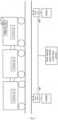
FIG. 3 is a schematic diagram of mounting electronic tags at the bottom of a train of the present disclosure; and -
FIG. 4 is a schematic diagram of mounting electronic tags on sides of the train of the present disclosure. - The technical solution in an embodiment of the present disclosure will be described clearly and completely below in conjunction with the accompanying drawings in the embodiment of the present disclosure. Obviously, the described embodiment is a part of embodiments of the present disclosure, not all of them. On the basis of the embodiment of the present disclosure, all other embodiments obtained by the person of ordinary skill in the art without involving any inventive effort should fall within the scope of protection of the present disclosure.
- The present disclosure provides a solution for detecting the train integrity by means of an RFID technology. The solution is easy to realize and convenient to mount and maintain, and there is no need to specially set technicians to mount train tail equipment, which reduces the labor cost and the later maintenance cost. In the solution, a group of two sets of ground RFID read-write equipment is used to ensure the accuracy and the reliability of read train head and tail vehicle electronic tags, so as to further improve the safety of a system and ensures the accuracy and safety of detection results.
- The solution of the present disclosure comprises mounting the RFID read-write equipment on a ground track, if the ground RFID read-write equipment is mounted on the whole line, the design and construction costs are excessively high, and thus the main features of the technical solution are as follows:
- (1) the solution mainly comprises the electronic tags (TAG) and the ground read-write equipment (wireless transceiver modules, antennas, control modules, communication units and power supplies);
- (2) contents of identification data stored in the electronic tags include tag IDs, line codes, area codes, station codes and speed levels;
- (3) ground RFID readers are mounted and arranged at tunnel entrances, station entrances and exits and some special areas according to site requirements;
- (4) locomotive electronic tags are mounted on bottom cross rails of locomotives and vehicles, or are mounted on side surfaces of the locomotives and the vehicles;
- (5) read electronic tag numbers of locomotive tag numbers and vehicle tail carriage tag numbers should be input, by a handheld card reader, to a system before the locomotives run;
- (6) the RFID read-write equipment is mounted between sleepers of the ground track or on the trackside;
- (7) the equipment adopts the integrated design, supports external AC220V DC power supply, and is arranged at the tunnel entrances, the station entrances and exits and some special areas of a line;
- (8) the RFID read-write equipment mounted on the ground track or the trackside reads the electronic tags at the head and tail of a train, and then sends read information to a train integrity detection system (TMIS) of the locomotive by means of the communication units of the equipment; and the TMIS calculates the train length according to stored locomotive and tail carriages corresponding to the electronic tags, received interval time sent by the electronic tags at the locomotive and the tail of the same train and the current speed and displacement of the train, so as to calculate the integrity of the train;
- (9) the TMIS must calculate, after receiving the train head and tail electronic tag information sent by the two pieces of RFID read-write equipment in one group on the ground, the train length Lw in meters respectively according to head and tail electronic tag data fed back by the two RFID readers and an actual interval Tb (L1w=LC1s- Lc1w, and L2w=LC2s- LC2w, wherein L1w represents the train length calculated by the first reader in one group, L2w represents the train length calculated by the second reader in the group, LC1s represents a mileage value when the first reader in the first group reads the tag at the head of the train, LC1w represents a mileage value when the first reader in the first group reads the tag at the tail of the train, LC2s represents a mileage value when the second reader in the first group reads the tag at the head of the train, and LC2w represents a mileage value when the second reader in the first group reads the tag at the tail of the train; and it is considered that transmission delay time Td of the two read data of the head and the tail can cancel each other and therefore can be omitted in the calculation formulas), only when the train length calculated by the two feedback electronic tags is complete, the train is considered to meet the integrity detection, and otherwise, a train integrity missing alarm is sent to an on-board ATP; and
- (10) the electronic tags are mounted on the locomotives and vehicles in the following two manners: (1) the electronic tags are mounted at the bottoms of the locomotives and the vehicles; and (2) the electronic tags are mounted on the side surfaces of the locomotives and the vehicles.
- The RFID electronic tags and the readers are mounted in the following two manners:
- (1) the RFID electronic tags are mounted on two sides of the carriages (with the mounting height matching that of the RFID readers and within the readable ranges of the RFID readers), and the RFID readers are mounted on the trackside and should be higher than lowest edges of carriage bodies of the carriages; the RFID readers are powered by trackside power supplies and are connected to the center by means of wired network channels, so as to send the received RFID electronic tags to a central processing server, the central processing server processes all the received tags and calculates the read-write interval time of the electronic tags at the head and the tail of the same locomotive and the length, so as to figure out the integrity state of the train, and the state is sent to a trackside control center, as shown in
FIG. 3 ; and - (2) the RFID readers are mounted in the track center, and the RFID electronic tags are mounted in the bottom centers of the vehicles. The mounting positions and intervals can be set according to the actual train operation interval time and distance on the specific site, as shown in
FIG. 4 . - As shown in
FIG. 1 , the RFID readers mounted on the ground track or the trackside read the electronic tags at the head and tail of the train, and then send the read information to the on-board train integrity detection system (TMIS) of the locomotive by means of the communication units of the readers, and the TMIS calculates the train length according to the stored locomotive and tail carriages corresponding to the electronic tags, the received interval time sent by the electronic tags at the locomotive and the tail of the same train and the current speed and displacement of the train, and calculates the integrity of the train according to the actual train length; and the process comprises the following steps: -
Step 1, when the head of the train presses theRFID reader 1 arranged on the ground, sending, by theground RFID reader 1, the electronic tag number of the head of the train to an RFID processing server of the ground train control center system, then transmitting the electronic tag number to the on-board train integrity detection system (TMIS) by means of an RBC, and acquiring, by the TMIS, train head locomotive information according to train information, corresponding to the electronic tag number, in a database and recording the speed, displacement and time of the current train; -
Step 2, when the tail of the train presses theRFID reader 1 arranged on the ground, sending, by theground RFID reader 1, the electronic tag number of the head of the train to the ground train control center system, then transmitting the electronic tag number to the on-board train integrity detection system (TMIS), and acquiring, by the TMIS, train tail locomotive information according to the train information, corresponding to the electronic tag number, in the database and recording the speed, displacement and time of the current train; -
Step 3, making judgment on whether a head locomotive number and a tail carriage number corresponding to the two read electronic tag numbers of the head and tail of the train belong to the head and tail of the current train according to the information stored in the database, calculating the train length according to a displacement value during the two times of pressing, and comparing the train length with the actual train length; and making pre-judgment, by the TMIS according to the two conditions, on whether the train is integral currently; -
Step 4, when the head of the train presses theRFID reader 2 arranged on the ground, sending, by theground RFID reader 2, the electronic tag number of the head of the train to the ground train control center system, then transmitting the electronic tag number to the on-board train integrity detection system (TMIS), and acquiring, by the TMIS, the train head locomotive information according to the train information, corresponding to the electronic tag number, in the database and recording the speed, displacement and time of the current train; -
Step 5, when the tail of the train presses theRFID reader 2 arranged on the ground, sending, by theground RFID reader 2, the electronic tag number of the head of the train to the RFID processing server of the ground train control center system, then transmitting the electronic tag number to the on-board train integrity detection system (TMIS) by means of the RBC, and acquiring, by the TMIS, train tail locomotive information according to train information, corresponding to the electronic tag number, in the database and recording the speed, displacement and time of the current train; -
Step 6, making judgment on whether a head locomotive number and a tail carriage number corresponding to the two electronic tag numbers of the head and tail of the train that are read by the RFID readers in a second group belong to the head and tail of the current train according to the information stored in the database, calculating the train length according to a displacement value during the two times of pressing, and comparing the train length with the actual train length; and making pre-judgment, by the TMIS according to the two conditions, on whether the train is integral currently; -
Step 7, calculating, by the TMIS, the train integrity state according to values returned by the two groups of RFID readers, with the judgment conditions as follows: if the train integrity judgment is met twice, the train is considered to be integral currently; otherwise, the train is considered to be not integral; and -
Step 8, if the train is not integral, sending a train integrity missing alarm to the on-board ATP. - As shown in
FIG. 2 , the internal structure and working principle of the ground RFID electronic tag read-write equipment are as follows: - (1) the ground RFID electronic tag read-write equipment is composed of the RFID reader, the RFID antenna, the communication unit, a core processor and the power supply;
- (2) after the train operates into the range that can be identified by the ground RFID electronic tag read-write equipment, the electronic tag receives a radio frequency signal sent by the reader and sends information, stored in a chip, by means of energy obtained through induction current, the reader decodes the received information and sends the information to the processor, the processor processes the information and then sends the received electronic tag to the ground train control center system by means of the network (in a wired/wireless manner), and then the electronic tag is sent by the RBC to the on-board TMIS; and
- (3) the on-board TMIS calculates the integrity of the train after receiving the electronic tag information.
- The present disclosure achieves the reliable detection of the train integrity by means of the mature RFID technology and the dual sets of ground RFID readers. The technical solution is simple in design principle, has a few intermediate links, is little disturbed and has few demands for personnel and maintenance, so that the construction and maintenance costs of the system can be greatly reduced under the condition that the demands of the system are met. Meanwhile, the electronic tags of the vehicles of the system can also be used in a train number identification system, so that multi-purpose application of one system is achieved, and the application and construction costs of the system can be further reduced; and the system has been recognized by local railway users at present, and is planned to be applied and promoted in the next step.
- The above is only the detailed description of the embodiments of the disclosure, but the scope of protection of the disclosure is defined by the appended claims only.
Claims (10)
- A train integrity detection device based on an RFID technology, the device comprising RFID electronic tags mounted to a head carriage and to a tail carriage of a train subject to train integrity detection, the train including a locomotive, RFID readers and a train integrity detection system, whereinthe RFID readers are mounted on a ground track or trackside and are configured to read the RFID electronic tags at the head carriage and tail carriage of a train, and then send read information to a train integrity detection system of the locomotive by means of communication units of the RFID readers; andthe train integrity detection system is configured to calculate the train's length according to stored train head and tail carriages data corresponding to the RFID electronic tags, an interval time defined by reading the RFID electronic tags at the head carriage and tail carriage of the train, and the current speed and displacement of the train, so as to calculate the integrity of the train.
- The device according to claim 1, wherein the train integrity detection system is configured to calculate, after receiving the train head carriage and tail carriage RFID electronic tag information sent by the two RFID readers forming a group on the ground, the train length respectively according to head carriage and tail carriage RFID electronic tag data fed back by the two RFID readers and an actual interval Tb.
- The device according to claim 2, wherein the train length is calculated as follows:L1w=LC1s-LC1w, and L2w=LC2s-LC2w, whereinL1w represents a train length calculated by a first RFID reader in the group, L2w represents a train length calculated by a second RFID reader in the group, LC1s represents a displacement value when the first RFID reader in the group reads the RFID electronic tag at the head carriage of the train, LC1w represents a displacement value when the first RFID reader in the group reads the RFID electronic tag at the tail carriage of the train, LC2s represents a displacement value when the second RFID reader in the group reads the RFID electronic tag at the head carriage of the train, and LC2w represents a displacement value when the second RFID reader in the group reads the RFID electronic tag at the tail carriage of the train; andonly when the train lengths L1w and L2w are completely calculated, the train is considered to meet the integrity detection.
- The device according to claim 1, wherein the RFID electronic tags are mounted on two sides of the carriages and are mounted at the height matching the mounting height of the RFID readers; or the RFID electronic tags are mounted on the trackside and should be higher than lowest edges of carriage bodies of the carriages.
- The device according to claim 1, wherein the RFID readers are mounted in the track center, and the RFID electronic tags are mounted in the bottom center of a vehicle.
- The device according to claim 1, wherein contents of identification data stored in each of the RFID electronic tags include tag IDs, line codes, area codes, station codes and speed level information.
- The device according to claim 1, wherein received electronic tags are sent by the RFID readers to a ground train control center system and then are sent to the train integrity detection system by the ground train control center system.
- A method for using the train integrity detection device based on an RFID technology according to claim 1, the method comprising the steps of:Step (1), when the RFID reader 1 arranged on the ground reads the RFID electronic tag mounted to the head carriage of the train, sending, by the RFID reader 1, an electronic tag number of the RFID electronic tag mounted to the head carriage of the train to the ground train control center system, then transmitting the electronic tag number to an on-board train integrity detection system (TMIS), and acquiring, by the TMIS, train head locomotive information according to train information, corresponding to the electronic tag number, in a database and recording the speed, displacement and time of the current train;Step (2), when the RFID reader 1 arranged on the ground reads the RFID electronic tag mounted to the tail of the train, sending, by the ground RFID reader 1, the electronic tag number of the RFID electronic tag mounted to the tail of the train to the ground train control center system, then transmitting the electronic tag number to the on-board train integrity detection system (TMIS), and acquiring, by the TMIS, train tail locomotive information according to the train information, corresponding to the electronic tag number, in the database and recording the speed, displacement and time of the current train;Step (3), making first pre-judgment by the TMIS on whether the train is integral currently;Step (4), when the RFID reader 2 arranged on the ground reads the RFID electronic tag mounted to the head carriage of the train, sending, by the ground RFID reader 2, the electronic tag number of the RFID electronic tag mounted to the head carriage of the train to the ground train control center system, then transmitting the electronic tag number to the on-board train integrity detection system (TMIS), and acquiring, by the TMIS, the train head locomotive information according to the train information, corresponding to the electronic tag number, in the database and recording the speed, displacement and time of the current train;Step (5), when the RFID reader 2 arranged on the ground reads the RFID electronic tag mounted to the tail of the train, sending, by the ground RFID reader 2, the electronic tag number of the RFID electronic tag mounted to the tail of the train to the ground train control center system, then transmitting the electronic tag number to the on-board train integrity detection system (TMIS), and acquiring, by the TMIS, train tail locomotive information according to the train information, corresponding to the electronic tag number, in the database and recording the speed, displacement and time of the current train;Step (6), making second pre-judgment by the TMIS on whether the train is integral currently;Step (7), calculating, by the TMIS, the train integrity state according to values returned by the two RFID readers, with the judgment conditions as follows: if the train integrity judgment is met twice, the train is considered to be integral currently; otherwise, the train is considered to be not integral; andStep (8), if the train is not integral, sending a train integrity missing alarm to an on-board ATP.
- The method according to claim 8, wherein making first pre-judgment by the TMIS on whether the train is integral currently in Step (3) specifically comprises:
judging, by the TMIS, whether a head locomotive number and a tail carriage number corresponding to the two electronic tag numbers of the RFID electronic tags mounted to the head carriage and tail carriage of the train that are read by the RFID reader 1 belong to the head carriage and tail carriage of the current train according to the information stored in the database, calculating the train length according to a displacement value during the two times of reading, and comparing the train length with the actual train length. - The method according to claim 8, wherein making second pre-judgment by the TMIS on whether the train is integral currently in Step (6) specifically comprises:
making judgment by the TMIS on whether a head locomotive number and a tail carriage number corresponding to the two electronic tag numbers of the RFID electronic tags mounted to the head carriage and tail carriage of the train that are read by the RFID reader 2 belong to the head carriage and tail carriage of the current train according to the information stored in the database, calculating the train length according to a displacement value during the two times of reading, and comparing the train length with the actual train length.
Applications Claiming Priority (2)
| Application Number | Priority Date | Filing Date | Title |
|---|---|---|---|
| CN202011305305.5A CN112429042B (en) | 2020-11-19 | 2020-11-19 | Train integrity detection device and method based on RFID technology |
| PCT/CN2021/119761 WO2022105414A1 (en) | 2020-11-19 | 2021-09-23 | Train integrity monitoring apparatus and method based on rfid technology |
Publications (3)
| Publication Number | Publication Date |
|---|---|
| EP4155165A1 EP4155165A1 (en) | 2023-03-29 |
| EP4155165A4 EP4155165A4 (en) | 2024-01-17 |
| EP4155165B1 true EP4155165B1 (en) | 2025-06-04 |
Family
ID=74694514
Family Applications (1)
| Application Number | Title | Priority Date | Filing Date |
|---|---|---|---|
| EP21893565.8A Active EP4155165B1 (en) | 2020-11-19 | 2021-09-23 | Train integrity monitoring apparatus and method based on rfid technology |
Country Status (3)
| Country | Link |
|---|---|
| EP (1) | EP4155165B1 (en) |
| CN (1) | CN112429042B (en) |
| WO (1) | WO2022105414A1 (en) |
Families Citing this family (13)
| Publication number | Priority date | Publication date | Assignee | Title |
|---|---|---|---|---|
| CN112429042B (en) * | 2020-11-19 | 2022-08-26 | 卡斯柯信号有限公司 | Train integrity detection device and method based on RFID technology |
| CN114089719B (en) * | 2021-10-27 | 2024-03-29 | 卡斯柯信号有限公司 | Vehicle signal interface simulation verification method and device for TACS system |
| CN114407979B (en) * | 2021-12-27 | 2023-08-29 | 卡斯柯信号有限公司 | Train integrity monitoring method, device, equipment and medium |
| CN115031640B (en) * | 2022-08-12 | 2022-11-01 | 广州运达智能科技有限公司 | Train wheel set online detection method, system, equipment and storage medium |
| CN115230772B (en) * | 2022-08-22 | 2023-07-28 | 南京恩瑞特实业有限公司 | A redundant protection method for urban rail train speed measurement and distance measurement |
| CN115626196A (en) * | 2022-10-31 | 2023-01-20 | 株洲中车时代电气股份有限公司 | Rail transit equipment detection system and method |
| CN115571195B (en) * | 2022-11-11 | 2024-11-01 | 卡斯柯信号有限公司 | A train length automatic detection device and method |
| CN116443051B (en) * | 2023-02-24 | 2025-07-29 | 浙江众合科技股份有限公司 | Device and method for identifying train consist of connected trains |
| CN115946740A (en) * | 2023-03-13 | 2023-04-11 | 广汉科峰电子有限责任公司 | Integrated train monitoring and identifying system |
| CN118010810A (en) * | 2024-04-08 | 2024-05-10 | 四川凯路威科技有限公司 | Device, method, equipment, medium and product for detecting integrity of concealed material |
| CN118810870B (en) * | 2024-06-24 | 2025-03-14 | 北京交通大学 | Train integrity status acquisition method based on optimization fuzzy reasoning |
| EP4717548A1 (en) * | 2024-09-26 | 2026-04-01 | Siemens Rail Automation S.A.U. | System and method for evaluating a time of use of a railway infrastructure |
| CN121234971A (en) * | 2025-09-29 | 2025-12-30 | 广州中铁信息工程有限公司 | Train tail running state monitoring FRD data acquisition system based on ultrahigh frequency identification |
Family Cites Families (9)
| Publication number | Priority date | Publication date | Assignee | Title |
|---|---|---|---|---|
| DE102004057545A1 (en) * | 2004-11-30 | 2006-06-08 | Alcatel | Train detachment automatic recognition method, involves recognizing detachment if distance determined between engine and last coach of train exceeds train length or if determined speed of coach falls below train speed, by given value |
| US10000222B2 (en) * | 2015-08-13 | 2018-06-19 | Lockheed Martin Corporation | Methods and systems of determining end of train location and clearance of trackside points of interest |
| DE102016212395A1 (en) * | 2016-07-07 | 2018-01-11 | Siemens Aktiengesellschaft | Method and device for determining a length of a track-bound vehicle |
| GB2560581B (en) * | 2017-03-17 | 2019-05-22 | Hitachi Rail Europe Ltd | Train integrity determination |
| CN107310591B (en) * | 2017-05-19 | 2020-05-19 | 中国神华能源股份有限公司 | Train integrity detection method, device, and system |
| CN108839677B (en) * | 2018-05-07 | 2021-04-13 | 中国铁路总公司 | Train integrity detection method and system |
| CN110745162A (en) * | 2019-09-04 | 2020-02-04 | 北京全路通信信号研究设计院集团有限公司 | Train integrity checking method and system |
| CN110758467B (en) * | 2019-10-28 | 2023-11-03 | 虞萍 | Preceding train integrity judging method and device based on time interval ratio |
| CN112429042B (en) * | 2020-11-19 | 2022-08-26 | 卡斯柯信号有限公司 | Train integrity detection device and method based on RFID technology |
-
2020
- 2020-11-19 CN CN202011305305.5A patent/CN112429042B/en active Active
-
2021
- 2021-09-23 EP EP21893565.8A patent/EP4155165B1/en active Active
- 2021-09-23 WO PCT/CN2021/119761 patent/WO2022105414A1/en not_active Ceased
Also Published As
| Publication number | Publication date |
|---|---|
| CN112429042B (en) | 2022-08-26 |
| CN112429042A (en) | 2021-03-02 |
| WO2022105414A1 (en) | 2022-05-27 |
| EP4155165A4 (en) | 2024-01-17 |
| EP4155165A1 (en) | 2023-03-29 |
Similar Documents
| Publication | Publication Date | Title |
|---|---|---|
| EP4155165A1 (en) | Train integrity monitoring apparatus and method based on rfid technology | |
| US6666411B1 (en) | Communications-based vehicle control system and method | |
| CN104884331B (en) | Urban railway transit train Anticollision information system | |
| CN105760802B (en) | Can identify train license number go forward side by side row position tracking device and its operation method | |
| CN202022221U (en) | RFID (radio frequency identification) assistant subway train position detection and precise parking system | |
| CN105346566B (en) | Bullet train is run close to early warning system and its implementation | |
| CN102167064A (en) | RFID (radio frequency identification devices)-assisted subway train position detecting and accurate parking system | |
| US10000222B2 (en) | Methods and systems of determining end of train location and clearance of trackside points of interest | |
| CN208978874U (en) | Train operation control system based on Big Dipper short message | |
| WO2021174866A1 (en) | Transmission method for receiving-route information and departure-route information, and system | |
| US20210016812A1 (en) | Train control system and train control method including virtual train stop | |
| CN108995677A (en) | The automatically-monitored management method in station track | |
| CN110422209B (en) | Control method and system for shunting operation of railway container freight yard | |
| CN110525484A (en) | Implementation method is calculated in station track based on BDS and STP at a distance from shunting service key point | |
| CN110843865B (en) | Train compartment marshalling identification system and method | |
| CN107215343A (en) | A kind of automated driving system applied to high-speed railway | |
| CN117775082A (en) | Rail transit backup degradation operation system and method based on secondary radar | |
| CN113147834B (en) | Auxiliary train positioning system and method for CBTC system | |
| CN110146308A (en) | For diagnosing method, server and the fault diagnosis system of bogie failure | |
| CN101186217B (en) | Structure for switching locomotive operation safety monitoring expert system | |
| CN206704213U (en) | A kind of tramcar operation control system based on truck traffic | |
| CN108860222A (en) | A kind of non-centralized interlocking area shunting service positioning system | |
| CN205788206U (en) | Be capable of identify that train license number go forward side by side line position follow the trail of device | |
| CN202011412U (en) | Real-time locomotive vehicle position tracking system | |
| CN221138102U (en) | System for calculating accurate stock of stock |
Legal Events
| Date | Code | Title | Description |
|---|---|---|---|
| STAA | Information on the status of an ep patent application or granted ep patent |
Free format text: STATUS: THE INTERNATIONAL PUBLICATION HAS BEEN MADE |
|
| PUAI | Public reference made under article 153(3) epc to a published international application that has entered the european phase |
Free format text: ORIGINAL CODE: 0009012 |
|
| STAA | Information on the status of an ep patent application or granted ep patent |
Free format text: STATUS: REQUEST FOR EXAMINATION WAS MADE |
|
| 17P | Request for examination filed |
Effective date: 20221223 |
|
| AK | Designated contracting states |
Kind code of ref document: A1 Designated state(s): AL AT BE BG CH CY CZ DE DK EE ES FI FR GB GR HR HU IE IS IT LI LT LU LV MC MK MT NL NO PL PT RO RS SE SI SK SM TR |
|
| A4 | Supplementary search report drawn up and despatched |
Effective date: 20231220 |
|
| RIC1 | Information provided on ipc code assigned before grant |
Ipc: B61L 3/12 20060101ALI20231214BHEP Ipc: B61L 1/14 20060101ALI20231214BHEP Ipc: B61L 15/00 20060101ALI20231214BHEP Ipc: B61L 27/00 20220101ALI20231214BHEP Ipc: B61L 25/04 20060101ALI20231214BHEP Ipc: B61L 25/02 20060101AFI20231214BHEP |
|
| DAV | Request for validation of the european patent (deleted) | ||
| DAX | Request for extension of the european patent (deleted) | ||
| STAA | Information on the status of an ep patent application or granted ep patent |
Free format text: STATUS: EXAMINATION IS IN PROGRESS |
|
| 17Q | First examination report despatched |
Effective date: 20240819 |
|
| GRAP | Despatch of communication of intention to grant a patent |
Free format text: ORIGINAL CODE: EPIDOSNIGR1 |
|
| STAA | Information on the status of an ep patent application or granted ep patent |
Free format text: STATUS: GRANT OF PATENT IS INTENDED |
|
| INTG | Intention to grant announced |
Effective date: 20250207 |
|
| GRAS | Grant fee paid |
Free format text: ORIGINAL CODE: EPIDOSNIGR3 |
|
| GRAA | (expected) grant |
Free format text: ORIGINAL CODE: 0009210 |
|
| STAA | Information on the status of an ep patent application or granted ep patent |
Free format text: STATUS: THE PATENT HAS BEEN GRANTED |
|
| AK | Designated contracting states |
Kind code of ref document: B1 Designated state(s): AL AT BE BG CH CY CZ DE DK EE ES FI FR GB GR HR HU IE IS IT LI LT LU LV MC MK MT NL NO PL PT RO RS SE SI SK SM TR |
|
| REG | Reference to a national code |
Ref country code: GB Ref legal event code: FG4D |
|
| REG | Reference to a national code |
Ref country code: CH Ref legal event code: EP |
|
| REG | Reference to a national code |
Ref country code: DE Ref legal event code: R096 Ref document number: 602021031949 Country of ref document: DE |
|
| REG | Reference to a national code |
Ref country code: IE Ref legal event code: FG4D |
|
| REG | Reference to a national code |
Ref country code: NL Ref legal event code: MP Effective date: 20250604 |
|
| PG25 | Lapsed in a contracting state [announced via postgrant information from national office to epo] |
Ref country code: FI Free format text: LAPSE BECAUSE OF FAILURE TO SUBMIT A TRANSLATION OF THE DESCRIPTION OR TO PAY THE FEE WITHIN THE PRESCRIBED TIME-LIMIT Effective date: 20250604 Ref country code: ES Free format text: LAPSE BECAUSE OF FAILURE TO SUBMIT A TRANSLATION OF THE DESCRIPTION OR TO PAY THE FEE WITHIN THE PRESCRIBED TIME-LIMIT Effective date: 20250604 |
|
| REG | Reference to a national code |
Ref country code: LT Ref legal event code: MG9D |
|
| PG25 | Lapsed in a contracting state [announced via postgrant information from national office to epo] |
Ref country code: NO Free format text: LAPSE BECAUSE OF FAILURE TO SUBMIT A TRANSLATION OF THE DESCRIPTION OR TO PAY THE FEE WITHIN THE PRESCRIBED TIME-LIMIT Effective date: 20250904 Ref country code: GR Free format text: LAPSE BECAUSE OF FAILURE TO SUBMIT A TRANSLATION OF THE DESCRIPTION OR TO PAY THE FEE WITHIN THE PRESCRIBED TIME-LIMIT Effective date: 20250905 |
|
| PG25 | Lapsed in a contracting state [announced via postgrant information from national office to epo] |
Ref country code: PL Free format text: LAPSE BECAUSE OF FAILURE TO SUBMIT A TRANSLATION OF THE DESCRIPTION OR TO PAY THE FEE WITHIN THE PRESCRIBED TIME-LIMIT Effective date: 20250604 |
|
| PGFP | Annual fee paid to national office [announced via postgrant information from national office to epo] |
Ref country code: TR Payment date: 20250915 Year of fee payment: 5 |
|
| PG25 | Lapsed in a contracting state [announced via postgrant information from national office to epo] |
Ref country code: BG Free format text: LAPSE BECAUSE OF FAILURE TO SUBMIT A TRANSLATION OF THE DESCRIPTION OR TO PAY THE FEE WITHIN THE PRESCRIBED TIME-LIMIT Effective date: 20250604 |
|
| PG25 | Lapsed in a contracting state [announced via postgrant information from national office to epo] |
Ref country code: HR Free format text: LAPSE BECAUSE OF FAILURE TO SUBMIT A TRANSLATION OF THE DESCRIPTION OR TO PAY THE FEE WITHIN THE PRESCRIBED TIME-LIMIT Effective date: 20250604 |
|
| PGFP | Annual fee paid to national office [announced via postgrant information from national office to epo] |
Ref country code: AT Payment date: 20251020 Year of fee payment: 5 Ref country code: FR Payment date: 20250926 Year of fee payment: 5 |
|
| PG25 | Lapsed in a contracting state [announced via postgrant information from national office to epo] |
Ref country code: RS Free format text: LAPSE BECAUSE OF FAILURE TO SUBMIT A TRANSLATION OF THE DESCRIPTION OR TO PAY THE FEE WITHIN THE PRESCRIBED TIME-LIMIT Effective date: 20250904 |
|
| PG25 | Lapsed in a contracting state [announced via postgrant information from national office to epo] |
Ref country code: LV Free format text: LAPSE BECAUSE OF FAILURE TO SUBMIT A TRANSLATION OF THE DESCRIPTION OR TO PAY THE FEE WITHIN THE PRESCRIBED TIME-LIMIT Effective date: 20250604 |
|
| PG25 | Lapsed in a contracting state [announced via postgrant information from national office to epo] |
Ref country code: NL Free format text: LAPSE BECAUSE OF FAILURE TO SUBMIT A TRANSLATION OF THE DESCRIPTION OR TO PAY THE FEE WITHIN THE PRESCRIBED TIME-LIMIT Effective date: 20250604 |
|
| PG25 | Lapsed in a contracting state [announced via postgrant information from national office to epo] |
Ref country code: PT Free format text: LAPSE BECAUSE OF FAILURE TO SUBMIT A TRANSLATION OF THE DESCRIPTION OR TO PAY THE FEE WITHIN THE PRESCRIBED TIME-LIMIT Effective date: 20251006 |
|
| REG | Reference to a national code |
Ref country code: AT Ref legal event code: MK05 Ref document number: 1800101 Country of ref document: AT Kind code of ref document: T Effective date: 20250604 |
|
| PG25 | Lapsed in a contracting state [announced via postgrant information from national office to epo] |
Ref country code: IS Free format text: LAPSE BECAUSE OF FAILURE TO SUBMIT A TRANSLATION OF THE DESCRIPTION OR TO PAY THE FEE WITHIN THE PRESCRIBED TIME-LIMIT Effective date: 20251004 |
|
| PG25 | Lapsed in a contracting state [announced via postgrant information from national office to epo] |
Ref country code: SM Free format text: LAPSE BECAUSE OF FAILURE TO SUBMIT A TRANSLATION OF THE DESCRIPTION OR TO PAY THE FEE WITHIN THE PRESCRIBED TIME-LIMIT Effective date: 20250604 Ref country code: AT Free format text: LAPSE BECAUSE OF FAILURE TO SUBMIT A TRANSLATION OF THE DESCRIPTION OR TO PAY THE FEE WITHIN THE PRESCRIBED TIME-LIMIT Effective date: 20250604 |
|
| PG25 | Lapsed in a contracting state [announced via postgrant information from national office to epo] |
Ref country code: CZ Free format text: LAPSE BECAUSE OF FAILURE TO SUBMIT A TRANSLATION OF THE DESCRIPTION OR TO PAY THE FEE WITHIN THE PRESCRIBED TIME-LIMIT Effective date: 20250604 |
|
| PG25 | Lapsed in a contracting state [announced via postgrant information from national office to epo] |
Ref country code: EE Free format text: LAPSE BECAUSE OF FAILURE TO SUBMIT A TRANSLATION OF THE DESCRIPTION OR TO PAY THE FEE WITHIN THE PRESCRIBED TIME-LIMIT Effective date: 20250604 |
|
| PG25 | Lapsed in a contracting state [announced via postgrant information from national office to epo] |
Ref country code: SK Free format text: LAPSE BECAUSE OF FAILURE TO SUBMIT A TRANSLATION OF THE DESCRIPTION OR TO PAY THE FEE WITHIN THE PRESCRIBED TIME-LIMIT Effective date: 20250604 |
|
| PG25 | Lapsed in a contracting state [announced via postgrant information from national office to epo] |
Ref country code: IT Free format text: LAPSE BECAUSE OF FAILURE TO SUBMIT A TRANSLATION OF THE DESCRIPTION OR TO PAY THE FEE WITHIN THE PRESCRIBED TIME-LIMIT Effective date: 20250604 |
|
| PG25 | Lapsed in a contracting state [announced via postgrant information from national office to epo] |
Ref country code: RO Free format text: LAPSE BECAUSE OF FAILURE TO SUBMIT A TRANSLATION OF THE DESCRIPTION OR TO PAY THE FEE WITHIN THE PRESCRIBED TIME-LIMIT Effective date: 20250604 |
|
| REG | Reference to a national code |
Ref country code: DE Ref legal event code: R097 Ref document number: 602021031949 Country of ref document: DE |
|
| PLBE | No opposition filed within time limit |
Free format text: ORIGINAL CODE: 0009261 |
|
| STAA | Information on the status of an ep patent application or granted ep patent |
Free format text: STATUS: NO OPPOSITION FILED WITHIN TIME LIMIT |
|
| PG25 | Lapsed in a contracting state [announced via postgrant information from national office to epo] |
Ref country code: DK Free format text: LAPSE BECAUSE OF FAILURE TO SUBMIT A TRANSLATION OF THE DESCRIPTION OR TO PAY THE FEE WITHIN THE PRESCRIBED TIME-LIMIT Effective date: 20250604 |
|
| REG | Reference to a national code |
Ref country code: CH Ref legal event code: L10 Free format text: ST27 STATUS EVENT CODE: U-0-0-L10-L00 (AS PROVIDED BY THE NATIONAL OFFICE) Effective date: 20260416 |
|
| REG | Reference to a national code |
Ref country code: CH Ref legal event code: H13 Free format text: ST27 STATUS EVENT CODE: U-0-0-H10-H13 (AS PROVIDED BY THE NATIONAL OFFICE) Effective date: 20260504 |
|
| 26N | No opposition filed |
Effective date: 20260305 |