EP4155059A2 - Method for joining dissimilar materials and joint of dissimilar materials - Google Patents
Method for joining dissimilar materials and joint of dissimilar materials Download PDFInfo
- Publication number
- EP4155059A2 EP4155059A2 EP22197100.5A EP22197100A EP4155059A2 EP 4155059 A2 EP4155059 A2 EP 4155059A2 EP 22197100 A EP22197100 A EP 22197100A EP 4155059 A2 EP4155059 A2 EP 4155059A2
- Authority
- EP
- European Patent Office
- Prior art keywords
- recess
- dissimilar materials
- joint
- present
- joining
- Prior art date
- Legal status (The legal status is an assumption and is not a legal conclusion. Google has not performed a legal analysis and makes no representation as to the accuracy of the status listed.)
- Granted
Links
Images



Classifications
-
- B—PERFORMING OPERATIONS; TRANSPORTING
- B29—WORKING OF PLASTICS; WORKING OF SUBSTANCES IN A PLASTIC STATE IN GENERAL
- B29C—SHAPING OR JOINING OF PLASTICS; SHAPING OF MATERIAL IN A PLASTIC STATE, NOT OTHERWISE PROVIDED FOR; AFTER-TREATMENT OF THE SHAPED PRODUCTS, e.g. REPAIRING
- B29C37/00—Component parts, details, accessories or auxiliary operations, not covered by group B29C33/00 or B29C35/00
- B29C37/0078—Measures or configurations for obtaining anchoring effects in the contact areas between layers
- B29C37/0082—Mechanical anchoring
-
- B—PERFORMING OPERATIONS; TRANSPORTING
- B29—WORKING OF PLASTICS; WORKING OF SUBSTANCES IN A PLASTIC STATE IN GENERAL
- B29C—SHAPING OR JOINING OF PLASTICS; SHAPING OF MATERIAL IN A PLASTIC STATE, NOT OTHERWISE PROVIDED FOR; AFTER-TREATMENT OF THE SHAPED PRODUCTS, e.g. REPAIRING
- B29C66/00—General aspects of processes or apparatus for joining preformed parts
- B29C66/01—General aspects dealing with the joint area or with the area to be joined
- B29C66/05—Particular design of joint configurations
- B29C66/303—Particular design of joint configurations the joint involving an anchoring effect
- B29C66/3032—Particular design of joint configurations the joint involving an anchoring effect making use of protrusions or cavities belonging to at least one of the parts to be joined
- B29C66/30325—Particular design of joint configurations the joint involving an anchoring effect making use of protrusions or cavities belonging to at least one of the parts to be joined making use of cavities belonging to at least one of the parts to be joined
-
- B—PERFORMING OPERATIONS; TRANSPORTING
- B23—MACHINE TOOLS; METAL-WORKING NOT OTHERWISE PROVIDED FOR
- B23K—SOLDERING OR UNSOLDERING; WELDING; CLADDING OR PLATING BY SOLDERING OR WELDING; CUTTING BY APPLYING HEAT LOCALLY, e.g. FLAME CUTTING; WORKING BY LASER BEAM
- B23K26/00—Working by laser beam, e.g. welding, cutting or boring
- B23K26/20—Bonding
- B23K26/32—Bonding taking account of the properties of the material involved
- B23K26/324—Bonding taking account of the properties of the material involved involving non-metallic parts
-
- B—PERFORMING OPERATIONS; TRANSPORTING
- B23—MACHINE TOOLS; METAL-WORKING NOT OTHERWISE PROVIDED FOR
- B23K—SOLDERING OR UNSOLDERING; WELDING; CLADDING OR PLATING BY SOLDERING OR WELDING; CUTTING BY APPLYING HEAT LOCALLY, e.g. FLAME CUTTING; WORKING BY LASER BEAM
- B23K26/00—Working by laser beam, e.g. welding, cutting or boring
- B23K26/36—Removing material
- B23K26/362—Laser etching
- B23K26/364—Laser etching for making a groove or trench, e.g. for scribing a break initiation groove
-
- B—PERFORMING OPERATIONS; TRANSPORTING
- B29—WORKING OF PLASTICS; WORKING OF SUBSTANCES IN A PLASTIC STATE IN GENERAL
- B29C—SHAPING OR JOINING OF PLASTICS; SHAPING OF MATERIAL IN A PLASTIC STATE, NOT OTHERWISE PROVIDED FOR; AFTER-TREATMENT OF THE SHAPED PRODUCTS, e.g. REPAIRING
- B29C45/00—Injection moulding, i.e. forcing the required volume of moulding material through a nozzle into a closed mould; Apparatus therefor
- B29C45/14—Injection moulding, i.e. forcing the required volume of moulding material through a nozzle into a closed mould; Apparatus therefor incorporating preformed parts or layers, e.g. injection moulding around inserts or for coating articles
- B29C45/14311—Injection moulding, i.e. forcing the required volume of moulding material through a nozzle into a closed mould; Apparatus therefor incorporating preformed parts or layers, e.g. injection moulding around inserts or for coating articles using means for bonding the coating to the articles
-
- B—PERFORMING OPERATIONS; TRANSPORTING
- B29—WORKING OF PLASTICS; WORKING OF SUBSTANCES IN A PLASTIC STATE IN GENERAL
- B29C—SHAPING OR JOINING OF PLASTICS; SHAPING OF MATERIAL IN A PLASTIC STATE, NOT OTHERWISE PROVIDED FOR; AFTER-TREATMENT OF THE SHAPED PRODUCTS, e.g. REPAIRING
- B29C65/00—Joining or sealing of preformed parts, e.g. welding of plastics materials; Apparatus therefor
- B29C65/02—Joining or sealing of preformed parts, e.g. welding of plastics materials; Apparatus therefor by heating, with or without pressure
- B29C65/14—Joining or sealing of preformed parts, e.g. welding of plastics materials; Apparatus therefor by heating, with or without pressure using wave energy, i.e. electromagnetic radiation, or particle radiation
- B29C65/16—Laser beams
-
- B—PERFORMING OPERATIONS; TRANSPORTING
- B29—WORKING OF PLASTICS; WORKING OF SUBSTANCES IN A PLASTIC STATE IN GENERAL
- B29C—SHAPING OR JOINING OF PLASTICS; SHAPING OF MATERIAL IN A PLASTIC STATE, NOT OTHERWISE PROVIDED FOR; AFTER-TREATMENT OF THE SHAPED PRODUCTS, e.g. REPAIRING
- B29C65/00—Joining or sealing of preformed parts, e.g. welding of plastics materials; Apparatus therefor
- B29C65/02—Joining or sealing of preformed parts, e.g. welding of plastics materials; Apparatus therefor by heating, with or without pressure
- B29C65/44—Joining a heated non plastics element to a plastics element
-
- B—PERFORMING OPERATIONS; TRANSPORTING
- B29—WORKING OF PLASTICS; WORKING OF SUBSTANCES IN A PLASTIC STATE IN GENERAL
- B29C—SHAPING OR JOINING OF PLASTICS; SHAPING OF MATERIAL IN A PLASTIC STATE, NOT OTHERWISE PROVIDED FOR; AFTER-TREATMENT OF THE SHAPED PRODUCTS, e.g. REPAIRING
- B29C65/00—Joining or sealing of preformed parts, e.g. welding of plastics materials; Apparatus therefor
- B29C65/56—Joining or sealing of preformed parts, e.g. welding of plastics materials; Apparatus therefor using mechanical means or mechanical connections, e.g. form-fits
- B29C65/64—Joining a non-plastics element to a plastics element, e.g. by force
-
- B—PERFORMING OPERATIONS; TRANSPORTING
- B29—WORKING OF PLASTICS; WORKING OF SUBSTANCES IN A PLASTIC STATE IN GENERAL
- B29C—SHAPING OR JOINING OF PLASTICS; SHAPING OF MATERIAL IN A PLASTIC STATE, NOT OTHERWISE PROVIDED FOR; AFTER-TREATMENT OF THE SHAPED PRODUCTS, e.g. REPAIRING
- B29C65/00—Joining or sealing of preformed parts, e.g. welding of plastics materials; Apparatus therefor
- B29C65/74—Joining or sealing of preformed parts, e.g. welding of plastics materials; Apparatus therefor by welding and severing, or by joining and severing, the severing being performed in the area to be joined, next to the area to be joined, in the joint area or next to the joint area
- B29C65/747—Joining or sealing of preformed parts, e.g. welding of plastics materials; Apparatus therefor by welding and severing, or by joining and severing, the severing being performed in the area to be joined, next to the area to be joined, in the joint area or next to the joint area using other than mechanical means
- B29C65/7473—Joining or sealing of preformed parts, e.g. welding of plastics materials; Apparatus therefor by welding and severing, or by joining and severing, the severing being performed in the area to be joined, next to the area to be joined, in the joint area or next to the joint area using other than mechanical means using radiation, e.g. laser, for simultaneously welding and severing
-
- B—PERFORMING OPERATIONS; TRANSPORTING
- B29—WORKING OF PLASTICS; WORKING OF SUBSTANCES IN A PLASTIC STATE IN GENERAL
- B29C—SHAPING OR JOINING OF PLASTICS; SHAPING OF MATERIAL IN A PLASTIC STATE, NOT OTHERWISE PROVIDED FOR; AFTER-TREATMENT OF THE SHAPED PRODUCTS, e.g. REPAIRING
- B29C66/00—General aspects of processes or apparatus for joining preformed parts
- B29C66/01—General aspects dealing with the joint area or with the area to be joined
- B29C66/02—Preparation of the material, in the area to be joined, prior to joining or welding
- B29C66/024—Thermal pre-treatments
- B29C66/0246—Cutting or perforating, e.g. burning away by using a laser or using hot air
-
- B—PERFORMING OPERATIONS; TRANSPORTING
- B29—WORKING OF PLASTICS; WORKING OF SUBSTANCES IN A PLASTIC STATE IN GENERAL
- B29C—SHAPING OR JOINING OF PLASTICS; SHAPING OF MATERIAL IN A PLASTIC STATE, NOT OTHERWISE PROVIDED FOR; AFTER-TREATMENT OF THE SHAPED PRODUCTS, e.g. REPAIRING
- B29C66/00—General aspects of processes or apparatus for joining preformed parts
- B29C66/01—General aspects dealing with the joint area or with the area to be joined
- B29C66/05—Particular design of joint configurations
- B29C66/10—Particular design of joint configurations particular design of the joint cross-sections
- B29C66/11—Joint cross-sections comprising a single joint-segment, i.e. one of the parts to be joined comprising a single joint-segment in the joint cross-section
- B29C66/112—Single lapped joints
- B29C66/1122—Single lap to lap joints, i.e. overlap joints
-
- B—PERFORMING OPERATIONS; TRANSPORTING
- B29—WORKING OF PLASTICS; WORKING OF SUBSTANCES IN A PLASTIC STATE IN GENERAL
- B29C—SHAPING OR JOINING OF PLASTICS; SHAPING OF MATERIAL IN A PLASTIC STATE, NOT OTHERWISE PROVIDED FOR; AFTER-TREATMENT OF THE SHAPED PRODUCTS, e.g. REPAIRING
- B29C66/00—General aspects of processes or apparatus for joining preformed parts
- B29C66/01—General aspects dealing with the joint area or with the area to be joined
- B29C66/05—Particular design of joint configurations
- B29C66/20—Particular design of joint configurations particular design of the joint lines, e.g. of the weld lines
- B29C66/21—Particular design of joint configurations particular design of the joint lines, e.g. of the weld lines said joint lines being formed by a single dot or dash or by several dots or dashes, i.e. spot joining or spot welding
-
- B—PERFORMING OPERATIONS; TRANSPORTING
- B29—WORKING OF PLASTICS; WORKING OF SUBSTANCES IN A PLASTIC STATE IN GENERAL
- B29C—SHAPING OR JOINING OF PLASTICS; SHAPING OF MATERIAL IN A PLASTIC STATE, NOT OTHERWISE PROVIDED FOR; AFTER-TREATMENT OF THE SHAPED PRODUCTS, e.g. REPAIRING
- B29C66/00—General aspects of processes or apparatus for joining preformed parts
- B29C66/01—General aspects dealing with the joint area or with the area to be joined
- B29C66/05—Particular design of joint configurations
- B29C66/20—Particular design of joint configurations particular design of the joint lines, e.g. of the weld lines
- B29C66/23—Particular design of joint configurations particular design of the joint lines, e.g. of the weld lines said joint lines being multiple and parallel or being in the form of tessellations
- B29C66/234—Particular design of joint configurations particular design of the joint lines, e.g. of the weld lines said joint lines being multiple and parallel or being in the form of tessellations said joint lines being in the form of tessellations
-
- B—PERFORMING OPERATIONS; TRANSPORTING
- B29—WORKING OF PLASTICS; WORKING OF SUBSTANCES IN A PLASTIC STATE IN GENERAL
- B29C—SHAPING OR JOINING OF PLASTICS; SHAPING OF MATERIAL IN A PLASTIC STATE, NOT OTHERWISE PROVIDED FOR; AFTER-TREATMENT OF THE SHAPED PRODUCTS, e.g. REPAIRING
- B29C66/00—General aspects of processes or apparatus for joining preformed parts
- B29C66/40—General aspects of joining substantially flat articles, e.g. plates, sheets or web-like materials; Making flat seams in tubular or hollow articles; Joining single elements to substantially flat surfaces
- B29C66/41—Joining substantially flat articles ; Making flat seams in tubular or hollow articles
- B29C66/45—Joining of substantially the whole surface of the articles
-
- B—PERFORMING OPERATIONS; TRANSPORTING
- B29—WORKING OF PLASTICS; WORKING OF SUBSTANCES IN A PLASTIC STATE IN GENERAL
- B29C—SHAPING OR JOINING OF PLASTICS; SHAPING OF MATERIAL IN A PLASTIC STATE, NOT OTHERWISE PROVIDED FOR; AFTER-TREATMENT OF THE SHAPED PRODUCTS, e.g. REPAIRING
- B29C66/00—General aspects of processes or apparatus for joining preformed parts
- B29C66/70—General aspects of processes or apparatus for joining preformed parts characterised by the composition, physical properties or the structure of the material of the parts to be joined; Joining with non-plastics material
- B29C66/74—Joining plastics material to non-plastics material
- B29C66/742—Joining plastics material to non-plastics material to metals or their alloys
-
- F—MECHANICAL ENGINEERING; LIGHTING; HEATING; WEAPONS; BLASTING
- F16—ENGINEERING ELEMENTS AND UNITS; GENERAL MEASURES FOR PRODUCING AND MAINTAINING EFFECTIVE FUNCTIONING OF MACHINES OR INSTALLATIONS; THERMAL INSULATION IN GENERAL
- F16B—DEVICES FOR FASTENING OR SECURING CONSTRUCTIONAL ELEMENTS OR MACHINE PARTS TOGETHER, e.g. NAILS, BOLTS, CIRCLIPS, CLAMPS, CLIPS OR WEDGES; JOINTS OR JOINTING
- F16B5/00—Joining sheets or plates, e.g. panels, to one another or to strips or bars parallel to them
- F16B5/08—Joining sheets or plates, e.g. panels, to one another or to strips or bars parallel to them by means of welds or the like
-
- B—PERFORMING OPERATIONS; TRANSPORTING
- B23—MACHINE TOOLS; METAL-WORKING NOT OTHERWISE PROVIDED FOR
- B23K—SOLDERING OR UNSOLDERING; WELDING; CLADDING OR PLATING BY SOLDERING OR WELDING; CUTTING BY APPLYING HEAT LOCALLY, e.g. FLAME CUTTING; WORKING BY LASER BEAM
- B23K2103/00—Materials to be soldered, welded or cut
- B23K2103/18—Dissimilar materials
-
- B—PERFORMING OPERATIONS; TRANSPORTING
- B29—WORKING OF PLASTICS; WORKING OF SUBSTANCES IN A PLASTIC STATE IN GENERAL
- B29C—SHAPING OR JOINING OF PLASTICS; SHAPING OF MATERIAL IN A PLASTIC STATE, NOT OTHERWISE PROVIDED FOR; AFTER-TREATMENT OF THE SHAPED PRODUCTS, e.g. REPAIRING
- B29C45/00—Injection moulding, i.e. forcing the required volume of moulding material through a nozzle into a closed mould; Apparatus therefor
- B29C45/14—Injection moulding, i.e. forcing the required volume of moulding material through a nozzle into a closed mould; Apparatus therefor incorporating preformed parts or layers, e.g. injection moulding around inserts or for coating articles
- B29C45/14311—Injection moulding, i.e. forcing the required volume of moulding material through a nozzle into a closed mould; Apparatus therefor incorporating preformed parts or layers, e.g. injection moulding around inserts or for coating articles using means for bonding the coating to the articles
- B29C2045/14327—Injection moulding, i.e. forcing the required volume of moulding material through a nozzle into a closed mould; Apparatus therefor incorporating preformed parts or layers, e.g. injection moulding around inserts or for coating articles using means for bonding the coating to the articles anchoring by forcing the material to pass through a hole in the article
-
- B—PERFORMING OPERATIONS; TRANSPORTING
- B29—WORKING OF PLASTICS; WORKING OF SUBSTANCES IN A PLASTIC STATE IN GENERAL
- B29C—SHAPING OR JOINING OF PLASTICS; SHAPING OF MATERIAL IN A PLASTIC STATE, NOT OTHERWISE PROVIDED FOR; AFTER-TREATMENT OF THE SHAPED PRODUCTS, e.g. REPAIRING
- B29C45/00—Injection moulding, i.e. forcing the required volume of moulding material through a nozzle into a closed mould; Apparatus therefor
- B29C45/14—Injection moulding, i.e. forcing the required volume of moulding material through a nozzle into a closed mould; Apparatus therefor incorporating preformed parts or layers, e.g. injection moulding around inserts or for coating articles
- B29C2045/1486—Details, accessories and auxiliary operations
- B29C2045/14868—Pretreatment of the insert, e.g. etching, cleaning
-
- B—PERFORMING OPERATIONS; TRANSPORTING
- B29—WORKING OF PLASTICS; WORKING OF SUBSTANCES IN A PLASTIC STATE IN GENERAL
- B29C—SHAPING OR JOINING OF PLASTICS; SHAPING OF MATERIAL IN A PLASTIC STATE, NOT OTHERWISE PROVIDED FOR; AFTER-TREATMENT OF THE SHAPED PRODUCTS, e.g. REPAIRING
- B29C2791/00—Shaping characteristics in general
- B29C2791/004—Shaping under special conditions
- B29C2791/009—Using laser
-
- B—PERFORMING OPERATIONS; TRANSPORTING
- B29—WORKING OF PLASTICS; WORKING OF SUBSTANCES IN A PLASTIC STATE IN GENERAL
- B29C—SHAPING OR JOINING OF PLASTICS; SHAPING OF MATERIAL IN A PLASTIC STATE, NOT OTHERWISE PROVIDED FOR; AFTER-TREATMENT OF THE SHAPED PRODUCTS, e.g. REPAIRING
- B29C66/00—General aspects of processes or apparatus for joining preformed parts
- B29C66/70—General aspects of processes or apparatus for joining preformed parts characterised by the composition, physical properties or the structure of the material of the parts to be joined; Joining with non-plastics material
- B29C66/71—General aspects of processes or apparatus for joining preformed parts characterised by the composition, physical properties or the structure of the material of the parts to be joined; Joining with non-plastics material characterised by the composition of the plastics material of the parts to be joined
-
- B—PERFORMING OPERATIONS; TRANSPORTING
- B29—WORKING OF PLASTICS; WORKING OF SUBSTANCES IN A PLASTIC STATE IN GENERAL
- B29C—SHAPING OR JOINING OF PLASTICS; SHAPING OF MATERIAL IN A PLASTIC STATE, NOT OTHERWISE PROVIDED FOR; AFTER-TREATMENT OF THE SHAPED PRODUCTS, e.g. REPAIRING
- B29C66/00—General aspects of processes or apparatus for joining preformed parts
- B29C66/70—General aspects of processes or apparatus for joining preformed parts characterised by the composition, physical properties or the structure of the material of the parts to be joined; Joining with non-plastics material
- B29C66/71—General aspects of processes or apparatus for joining preformed parts characterised by the composition, physical properties or the structure of the material of the parts to be joined; Joining with non-plastics material characterised by the composition of the plastics material of the parts to be joined
- B29C66/712—General aspects of processes or apparatus for joining preformed parts characterised by the composition, physical properties or the structure of the material of the parts to be joined; Joining with non-plastics material characterised by the composition of the plastics material of the parts to be joined the composition of one of the parts to be joined being different from the composition of the other part
-
- B—PERFORMING OPERATIONS; TRANSPORTING
- B29—WORKING OF PLASTICS; WORKING OF SUBSTANCES IN A PLASTIC STATE IN GENERAL
- B29C—SHAPING OR JOINING OF PLASTICS; SHAPING OF MATERIAL IN A PLASTIC STATE, NOT OTHERWISE PROVIDED FOR; AFTER-TREATMENT OF THE SHAPED PRODUCTS, e.g. REPAIRING
- B29C66/00—General aspects of processes or apparatus for joining preformed parts
- B29C66/70—General aspects of processes or apparatus for joining preformed parts characterised by the composition, physical properties or the structure of the material of the parts to be joined; Joining with non-plastics material
- B29C66/74—Joining plastics material to non-plastics material
- B29C66/742—Joining plastics material to non-plastics material to metals or their alloys
- B29C66/7422—Aluminium or alloys of aluminium
-
- B—PERFORMING OPERATIONS; TRANSPORTING
- B29—WORKING OF PLASTICS; WORKING OF SUBSTANCES IN A PLASTIC STATE IN GENERAL
- B29C—SHAPING OR JOINING OF PLASTICS; SHAPING OF MATERIAL IN A PLASTIC STATE, NOT OTHERWISE PROVIDED FOR; AFTER-TREATMENT OF THE SHAPED PRODUCTS, e.g. REPAIRING
- B29C66/00—General aspects of processes or apparatus for joining preformed parts
- B29C66/70—General aspects of processes or apparatus for joining preformed parts characterised by the composition, physical properties or the structure of the material of the parts to be joined; Joining with non-plastics material
- B29C66/74—Joining plastics material to non-plastics material
- B29C66/742—Joining plastics material to non-plastics material to metals or their alloys
- B29C66/7428—Transition metals or their alloys
- B29C66/74281—Copper or alloys of copper
-
- B—PERFORMING OPERATIONS; TRANSPORTING
- B29—WORKING OF PLASTICS; WORKING OF SUBSTANCES IN A PLASTIC STATE IN GENERAL
- B29C—SHAPING OR JOINING OF PLASTICS; SHAPING OF MATERIAL IN A PLASTIC STATE, NOT OTHERWISE PROVIDED FOR; AFTER-TREATMENT OF THE SHAPED PRODUCTS, e.g. REPAIRING
- B29C66/00—General aspects of processes or apparatus for joining preformed parts
- B29C66/70—General aspects of processes or apparatus for joining preformed parts characterised by the composition, physical properties or the structure of the material of the parts to be joined; Joining with non-plastics material
- B29C66/74—Joining plastics material to non-plastics material
- B29C66/742—Joining plastics material to non-plastics material to metals or their alloys
- B29C66/7428—Transition metals or their alloys
- B29C66/74283—Iron or alloys of iron, e.g. steel
-
- B—PERFORMING OPERATIONS; TRANSPORTING
- B29—WORKING OF PLASTICS; WORKING OF SUBSTANCES IN A PLASTIC STATE IN GENERAL
- B29C—SHAPING OR JOINING OF PLASTICS; SHAPING OF MATERIAL IN A PLASTIC STATE, NOT OTHERWISE PROVIDED FOR; AFTER-TREATMENT OF THE SHAPED PRODUCTS, e.g. REPAIRING
- B29C66/00—General aspects of processes or apparatus for joining preformed parts
- B29C66/70—General aspects of processes or apparatus for joining preformed parts characterised by the composition, physical properties or the structure of the material of the parts to be joined; Joining with non-plastics material
- B29C66/74—Joining plastics material to non-plastics material
- B29C66/746—Joining plastics material to non-plastics material to inorganic materials not provided for in groups B29C66/742 - B29C66/744
- B29C66/7461—Ceramics
Definitions
- the present invention relates to a method for joining dissimilar materials and a joint of dissimilar materials.
- Japanese Patent No. 4020957 is a prior art document disclosing a method for machining a metal material having a joining part with a dissimilar material using a laser.
- the joining part for joining with the dissimilar material is formed by laser scanning a metal surface in a scanning direction and another scanning direction crossing the scanning direction. The dissimilar material is joined to the metal surface subjected to laser scanning.
- the present invention has been made to solve the above-described problems, and it is therefore an object of the present invention to provide a method for joining dissimilar materials and a joint of dissimilar materials that can eliminate a low-strength direction in which a joint strength between dissimilar materials joined to each other is low to suppress separation of the dissimilar materials.
- a method for joining dissimilar materials includes forming a first recess and a second recess by irradiating a surface of a first member with laser light, the first recess and the second recess being cut into the surface obliquely at angles different from each other, and joining a second member to the surface of the first member with a part of the second member engaging with each of the first recess and the second recess by melting the part of the second member lower in melting point than the first member to cause the part of the second member to flow into each of the first recess and the second recess and solidifying the part of the second member.
- Causing the part of the second member to engage with each of the first recess and the second recess cut into the surface of the first member obliquely at angles different from each other makes it possible to eliminate a low-strength direction in which a joint strength between the first member and the second member joined to each other is low to suppress separation of the first member and the second member.
- At least one of the first recess and the second recess is formed in a linear shape in the surface.
- At least one of the first recess and the second recess is formed in a spot shape.
- the first member is formed of a metal material
- the second member is formed of a resin material
- the metal material and the resin material can be joined to each other as dissimilar materials.
- a joint of dissimilar materials includes a first member and a second member.
- the first member has a first recess and a second recess cut into a surface of the first member obliquely at angles different from each other.
- the second member is lower in melting point than the first member and joined to the surface of the first member. A part of the second member flows into each of the first recess and the second recess to engage with each of the first recess and the second recess.
- Causing the part of the second member to engage with each of the first recess and the second recess cut into the surface of the first member obliquely at angles different from each other makes it possible to eliminate a low-strength direction in which a joint strength between the first member and the second member joined to each other is low to suppress separation of the first member and the second member.
- a direction parallel to a surface of a first member is defined as an X direction
- a direction orthogonal to the X direction on the surface of the first member is defined as a Y direction
- a direction orthogonal to the surface of the first member is defined as a Z direction.
- Fig. 1 is a perspective view of a configuration of a joint of dissimilar materials according to a first embodiment of the present invention.
- Fig. 2 is a cross-sectional view of the joint illustrated in Fig. 1 when viewed in the direction of a II-II arrow.
- a joint 1 of dissimilar materials includes a first member 10 and a second member 20.
- first member 10 has an approximately rectangular parallelepiped shape.
- the shape of first member 10, however, is not limited to the rectangular parallelepiped shape.
- First member 10 is formed of a metal material.
- the material of first member 10 is, for example, aluminum.
- the material of first member 10 is not limited to aluminum and may be a metal material such as iron or copper.
- first member 10 is not limited to a metal material as long as laser machining can be performed, and may be a resin material, ceramics, or the like.
- First member 10 has a first recess 100 and a second recess 110 cut into the surface of first member 10 obliquely at angles different from each other.
- first recess 100 and second recess 110 are formed so as to come closer to each other as being away from the surface (XY plane) of first member 10. That is, first recess 100 and second recess 110 are formed so as to be spaced apart from each other relative to a virtual plane (XZ plane) perpendicular to the surface of first member 10 and to come closer to each other at their tip sides in a cutting direction.
- first recess 100 and second recess 110 may be formed plane-symmetrically with respect to the virtual plane (XZ plane).
- First recess 100 and second recess 110 are each formed extending in, for example, an oblique direction intersecting the surface of first member 10 at an angle in a range of greater than or equal to 60° and less than or equal to 80° when viewed in the X direction.
- the angles at which first recess 100 and second recess 110 intersect the surface of first member 10 only need to be different from each other, and are not limited to being within the above-described range of greater than or equal to 60° and less than or equal to 80°.
- one first recess 100 and one second recess 110 are formed in the surface of first member 10, but at least one of first recess 100 and second recess 110 may be formed at a plurality places.
- a recess may be formed by cutting the surface at an angle different from the angles of first recess 100 and second recess 110.
- first recess 100 and second recess 110 may be formed in a linear shape in the surface of first member 10.
- first recess 100 and second recess 110 are each formed in a linear shape extending in the X direction in the surface of first member 10.
- first recess 100 and second recess 110 are each formed in a linear shape in the surface of first member 10, but may be formed in a curved shape.
- second member 20 has an approximately rectangular parallelepiped shape.
- the shape of second member 20, however, is not limited to a rectangular parallelepiped shape.
- Second member 20 is made of a material lower in melting point than first member 10.
- second member 20 is made of a resin material.
- Second member 20 is made of, for example, polypropylene.
- the material of second member 20 is not limited to polypropylene, and may be a resin material such as polycarbonate or polyamide.
- the material of second member 20 is not limited to a resin material and may be a metal material.
- Second member 20 is lower in melting point than first member 10 by, for example, at least 100°C.
- Second member 20 is adjacent to first member 10 in the Z direction. Second member 20 is joined to the surface of first member 10.
- Second member 20 partially flows into each of first recess 100 and second recess 110 to engage with each of first recess 100 and second recess 110.
- a first projection 120 and a second projection 130 are formed on second member 20.
- First projection 120 is formed to adapt to an internal shape of first recess 100 and engages with first recess 100.
- Second projection 130 is formed to adapt to an internal shape of second recess 110 and engages with second recess 110.
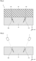
- FIG. 3 is a cross-sectional view of the first member, illustrating a state where the first member is irradiated with laser light to form the first recess and the second recess under the method for joining dissimilar materials according to the first embodiment of the present invention.
- first, the surface of first member 10 is irradiated with laser light to form first recess 100 and second recess 110, first recess 100 and second recess 110 being cut into the surface of first member 10 obliquely at angles different from each other.
- first recess 100 and second recess 110 are each formed by irradiation of the surface of first member 10 with laser light emitted from a laser oscillator 2.
- the laser light is emitted from laser oscillator 2 obliquely to the surface of first member 10.
- first recess 100 and second recess 110 may be formed by one pulse irradiation with laser light, may be formed by a plurality of times of pulse irradiation with laser light, or may be formed by continuous irradiation with laser light.
- Various conditions such as the power of the laser light emitted from laser oscillator 2 are suitably adjusted to material characteristics of first member 10.
- a part of second member 20 is melted to flow into each of first recess 100 and second recess 110 and then solidify, thereby causing second member 20 to join to the surface of first member 10 with the part of second member 20 engaging with each of first recess 100 and second recess 110.
- the part of second member 20 is melted to flow into each of first recess 100 and second recess 110 and then solidify by injection molding, for example.
- the method by which second member 20 is melted to flow is not limited to injection molding, and may be a method by which heat is applied to second member 20 through first member 10 to melt the part of second member 20 in contact with first member 10.
- first recess and the second recess cut into the surface of first member 10 in the same direction perpendicular or oblique to the surface of first member 10, when a load of separating first member 10 and second member 20 is applied in the direction in which the first recess and second recess are cut, the first projection easily separates from the first recess, the second projection easily separates from the second recess, and the joint between the first member and the second member becomes significantly weak accordingly.
- first recess and the second recess are cut into the surface of first member 10 in the same direction perpendicular or oblique to the surface of first member 10, the joint strength against the load of separating the first member and the second member in the low-strength direction along the direction is significantly reduced, and first member 10 and second member 20 easily separate from each other accordingly.
- first projection 120 does not easily separate from first recess 100 cut at an angle different from second recess 110, so that the joint strength between first member 10 and second member 20 can be made higher.
- the low-strength direction in which the joint strength between first member 10 and second member 20 joined to each other is low can be eliminated to suppress separation of first member 10 and second member 20.
- the method for joining dissimilar materials and joint 1 of dissimilar materials according to the first embodiment of the present invention can suppress separation of the dissimilar materials by causing the part of second member 20 to engage with each of first recess 100 and second recess 110 cut into the surface of first member 10 obliquely at angles different from each other to eliminate the low-strength direction in which the joint strength between the dissimilar materials joined to each other is low.
- the method for joining dissimilar materials and joint 1 of dissimilar materials according to the first embodiment of the present invention can suppress separation of first member 10 and second member 20 by forming at least one of first recess 100 and second recess 110 in a linear shape in the surface of first member 10 to increasing the joint strength between first member 10 and second member 20.
- the method for joining dissimilar materials and joint 1 of dissimilar materials according to the first embodiment of the present invention can join, with first member 10 formed of a metal material, and second member 20 formed of a resin material, the metal material and the resin material as dissimilar materials.
- Fig. 4 is a cross-sectional view of a configuration of a joint of dissimilar materials according to a first modification of the first embodiment of the present invention.
- a joint 1A of dissimilar materials according to the first modification of the first embodiment of the present invention includes a first member 10A and a second member 20A.
- First member 10A has a first recess 101 and a second recess 111 cut into the surface of first member 10A obliquely at angles different from each other.
- a joining part 141 is formed at their respective tips, in the cutting direction, of first recess 101 and second recess 111. Joining part 141 causes first recess 101 and second recess 111 to communicate with each other.
- a part of second member 20A flows into each of first recess 101 and second recess 111 to engage with each of first recess 101 and second recess 111.
- a first projection 121 and a second projection 131 are formed on second member 20A.
- First projection 121 engages with first recess 101
- second projection 131 engages with second recess 111.
- First projection 121 and second projection 131 are joined at joining part 141.
- the method for joining dissimilar materials and joint 1A of dissimilar materials according to the first modification of the first embodiment of the present invention can suppress separation of the dissimilar materials by joining, at joining part 141, first projection 121 and second projection 131, each of which being a part of second member 20A, and causing the part of second member 20A to engage with each of first recess 101 and second recess 111 to eliminate the low-strength direction in which the joint strength between the dissimilar materials joined to each other is low and increase the joint strength between the dissimilar materials.
- Fig. 5 is a cross-sectional view of a configuration of a joint of dissimilar materials according to a second modification of the first embodiment of the present invention.
- a joint 1B of dissimilar materials according to the second modification of the first embodiment of the present invention includes a first member 10B and a second member 20B.
- First member 10B has a first recess 102 and a second recess 112 cut into the surface of first member 10B obliquely at angles different from each other. According to the present modification, first recess 102 and second recess 112 intersect each other to form a joining part 142 at the intersection. Joining part 142 causes first recess 102 and second recess 112 to communicate with each other.
- a part of second member 20B flows into each of first recess 102 and second recess 112 to engage with each of first recess 102 and second recess 112.
- a first projection 122 and a second projection 132 are formed on second member 20B.
- First projection 122 engages with first recess 102
- second projection 132 engages with second recess 112.
- First projection 122 and second projection 132 are joined at joining part 142.
- the method for joining dissimilar materials and joint 1B of dissimilar materials according to the second modification of the first embodiment of the present invention can suppress separation of the dissimilar materials by joining, at joining part 142, first projection 122 and second projection 132, each of which being a part of second member 20B, and causing the part of second member 20B to engage with each of first recess 102 and second recess 112 to eliminate the low-strength direction in which the joint strength between the dissimilar materials joined to each other is low and increase the joint strength between the dissimilar materials.
- the method for joining dissimilar materials and the joint of dissimilar materials according to the second embodiment of the present invention are different from the method for joining dissimilar materials and joint 1 of dissimilar materials according to the first embodiment of the present invention only in configuration of the first recess and in configuration of the second recess, so that no description will be given below of the same configurations as in the method for joining dissimilar materials and joint 1 of dissimilar materials according to the first embodiment of the present invention.
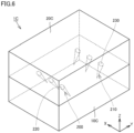
- Fig. 6 is a perspective view of a configuration of the joint of dissimilar materials according to the second embodiment of the present invention.
- a joint 1C of dissimilar materials according to the second embodiment of the present invention includes a first member 10C and a second member 20C.
- First member 10C has a first recess 200 and a second recess 210 cut into the surface of first member 10C obliquely at angles different from each other. At least one of first recess 200 and second recess 210 is formed in a spot shape. According to the present embodiment, first recess 200 and second recess 210 are each formed in a spot shape. A plurality of first recesses 200 and a plurality of second recesses 210 are arranged side by side in the X direction.
- a part of second member 20C flows into each of first recess 200 and second recess 210 to engage with each of first recess 200 and second recess 210.
- a first projection 220 and a second projection 230 are formed on second member 20C.
- First projection 220 engages with first recess 200
- second projection 230 engages with second recess 210.
- the method for joining dissimilar materials and joint 1C of dissimilar materials according to the second embodiment of the present invention can reduce energy required for irradiation with laser light by forming at least one of first recess 200 and second recess 210 in a spot shape as compared with a case where the first recess and the second recess are each formed in a linear shape.
- the method for joining dissimilar materials and the joint of dissimilar materials according to the third embodiment of the present invention are different from the method for joining dissimilar materials and joint 1 of dissimilar materials according to the first embodiment of the present invention mainly in configuration of the first member, so that no description will be given below of the same configurations as in the method for joining dissimilar materials and joint 1 of dissimilar materials according to the first embodiment of the present invention.
- Fig. 7 is a top view of a configuration of the first member of the joint of dissimilar materials according to the third embodiment of the present invention. Note that Fig. 7 illustrates a second member in a see-through manner for easy understanding.
- a joint 1D of dissimilar materials includes a first member 10D and the second member.
- First member 10D has a first recess 300, a second recess 310, and a third recess 320 cut into the surface of first member 10D obliquely at angles different from each other.
- First recess 300, second recess 310, and third recess 320 linearly extend to intersect each other at an angle of about 60° on the XY plane.
- a plurality of triangles surrounded by first recess 300, second recess 310, and third recess 320 are formed in the surface of first member 10D.
- Their respective tips, in the cutting direction, of first recess 300, second recess 310, and third recess 320 are located inside the triangles when viewed in the Z direction. That is, first recess 300, second recess 310, and third recess 320 are each formed extending along a corresponding peripheral surface of each triangular frustum.
- first recess 300, second recess 310, and third recess 320 are configured to form a plurality of triangular shapes in the surface of first member 10D, but the present disclosure is not limited to such a configuration, and at least four types of recesses may be cut into the surface of first member 10D obliquely at angles different from each other to form polygons each having four sides or more in the surface of first member 10D.
- the method for joining dissimilar materials and joint 1D of dissimilar materials can suppress separation of the dissimilar materials by forming polygons in the surface of first member 10D with a plurality of recesses cut into the surface of first member 10D obliquely at angles different from each other to eliminate the low-strength direction in which the joint strength between the dissimilar materials joined to each other is low and forming the part of the second member to surround all peripheries of polygonal frustum to increase the joint strength between the dissimilar material.
Landscapes
- Engineering & Computer Science (AREA)
- Mechanical Engineering (AREA)
- Physics & Mathematics (AREA)
- Optics & Photonics (AREA)
- Plasma & Fusion (AREA)
- General Engineering & Computer Science (AREA)
- Toxicology (AREA)
- Health & Medical Sciences (AREA)
- Electromagnetism (AREA)
- Thermal Sciences (AREA)
- Manufacturing & Machinery (AREA)
- Laser Beam Processing (AREA)
- Lining Or Joining Of Plastics Or The Like (AREA)
Abstract
Description
- The present invention relates to a method for joining dissimilar materials and a joint of dissimilar materials.
-
Japanese Patent No. 4020957 Japanese Patent No. 4020957 - When a surface of one of dissimilar materials is irradiated with laser light in one irradiation direction to join the dissimilar materials using the surface irradiated with the laser light, a joint strength between the dissimilar materials against a load of separating the dissimilar materials in a low-strength direction along the one irradiation direction is low, and the dissimilar materials joined to each other are easily separated.
- The present invention has been made to solve the above-described problems, and it is therefore an object of the present invention to provide a method for joining dissimilar materials and a joint of dissimilar materials that can eliminate a low-strength direction in which a joint strength between dissimilar materials joined to each other is low to suppress separation of the dissimilar materials.
- A method for joining dissimilar materials according to an aspect of the present invention includes forming a first recess and a second recess by irradiating a surface of a first member with laser light, the first recess and the second recess being cut into the surface obliquely at angles different from each other, and joining a second member to the surface of the first member with a part of the second member engaging with each of the first recess and the second recess by melting the part of the second member lower in melting point than the first member to cause the part of the second member to flow into each of the first recess and the second recess and solidifying the part of the second member.
- Causing the part of the second member to engage with each of the first recess and the second recess cut into the surface of the first member obliquely at angles different from each other makes it possible to eliminate a low-strength direction in which a joint strength between the first member and the second member joined to each other is low to suppress separation of the first member and the second member.
- According to another aspect of the present invention, at least one of the first recess and the second recess is formed in a linear shape in the surface.
- This can make the joint strength between the first member and the second member higher to suppress separation of the first member and the second member.
- According to another aspect of the present invention, at least one of the first recess and the second recess is formed in a spot shape.
- This allows a reduction in energy required for irradiation with laser light.
- According to another aspect of the present invention, the first member is formed of a metal material, and the second member is formed of a resin material.
- In this case, the metal material and the resin material can be joined to each other as dissimilar materials.
- A joint of dissimilar materials according to an aspect of the present invention includes a first member and a second member. The first member has a first recess and a second recess cut into a surface of the first member obliquely at angles different from each other. The second member is lower in melting point than the first member and joined to the surface of the first member. A part of the second member flows into each of the first recess and the second recess to engage with each of the first recess and the second recess.
- Causing the part of the second member to engage with each of the first recess and the second recess cut into the surface of the first member obliquely at angles different from each other makes it possible to eliminate a low-strength direction in which a joint strength between the first member and the second member joined to each other is low to suppress separation of the first member and the second member.
- The foregoing and other objects, features, aspects, and advantages of the present invention will become more apparent from the following detailed description of the present invention when taken in conjunction with the accompanying drawings.
-
-
Fig. 1 is a perspective view of a configuration of a joint of dissimilar materials according to a first embodiment of the present invention. -
Fig. 2 is a cross-sectional view of the joint illustrated inFig. 1 when viewed in the direction of a II-II arrow. -
Fig. 3 is a cross-sectional view of a first member, illustrating a state where the first member is irradiated with laser light to form a first recess and a second recess under a method for joining dissimilar materials according to the first embodiment of the present invention. -
Fig. 4 is a cross-sectional view of a configuration of a joint of dissimilar materials according to a first modification of the first embodiment of the present invention. -
Fig. 5 is a cross-sectional view of a configuration of a joint of dissimilar materials according to a second modification of the first embodiment of the present invention. -
Fig. 6 is a perspective view of a configuration of a joint of dissimilar materials according to a second embodiment of the present invention. -
Fig. 7 is a top view of a configuration of a first member of a joint of dissimilar materials according to a third embodiment of the present invention. - Hereinafter, a method for joining dissimilar materials and a joint of dissimilar materials according to each embodiment of the present invention will be described with reference to the drawings. In the following description of the embodiments, the same or corresponding parts in the drawings are denoted by the same reference numerals to avoid the description from being redundant.
- In the drawings, a direction parallel to a surface of a first member is defined as an X direction, a direction orthogonal to the X direction on the surface of the first member is defined as a Y direction, and a direction orthogonal to the surface of the first member is defined as a Z direction.
-
Fig. 1 is a perspective view of a configuration of a joint of dissimilar materials according to a first embodiment of the present invention.Fig. 2 is a cross-sectional view of the joint illustrated inFig. 1 when viewed in the direction of a II-II arrow. - As illustrated in
Figs. 1 and2 , a joint 1 of dissimilar materials according to the first embodiment of the present invention includes afirst member 10 and asecond member 20. - According to the present embodiment,
first member 10 has an approximately rectangular parallelepiped shape. The shape offirst member 10, however, is not limited to the rectangular parallelepiped shape. -
First member 10 is formed of a metal material. The material offirst member 10 is, for example, aluminum. Note that the material offirst member 10 is not limited to aluminum and may be a metal material such as iron or copper. Furthermore,first member 10 is not limited to a metal material as long as laser machining can be performed, and may be a resin material, ceramics, or the like. -
First member 10 has afirst recess 100 and asecond recess 110 cut into the surface offirst member 10 obliquely at angles different from each other. According to the present embodiment,first recess 100 andsecond recess 110 are formed so as to come closer to each other as being away from the surface (XY plane) offirst member 10. That is,first recess 100 andsecond recess 110 are formed so as to be spaced apart from each other relative to a virtual plane (XZ plane) perpendicular to the surface offirst member 10 and to come closer to each other at their tip sides in a cutting direction. For example,first recess 100 andsecond recess 110 may be formed plane-symmetrically with respect to the virtual plane (XZ plane). -
First recess 100 andsecond recess 110 according to the present embodiment are each formed extending in, for example, an oblique direction intersecting the surface offirst member 10 at an angle in a range of greater than or equal to 60° and less than or equal to 80° when viewed in the X direction. The angles at which first recess 100 andsecond recess 110 intersect the surface offirst member 10 only need to be different from each other, and are not limited to being within the above-described range of greater than or equal to 60° and less than or equal to 80°. Note that, according to the present embodiment, onefirst recess 100 and onesecond recess 110 are formed in the surface offirst member 10, but at least one offirst recess 100 andsecond recess 110 may be formed at a plurality places. Further, in the surface offirst member 10, a recess may be formed by cutting the surface at an angle different from the angles offirst recess 100 andsecond recess 110. - At least one of
first recess 100 andsecond recess 110 may be formed in a linear shape in the surface offirst member 10. According to the present embodiment,first recess 100 andsecond recess 110 are each formed in a linear shape extending in the X direction in the surface offirst member 10. Note that, according to the present embodiment,first recess 100 andsecond recess 110 are each formed in a linear shape in the surface offirst member 10, but may be formed in a curved shape. - According to the present embodiment,
second member 20 has an approximately rectangular parallelepiped shape. The shape ofsecond member 20, however, is not limited to a rectangular parallelepiped shape. -
Second member 20 is made of a material lower in melting point thanfirst member 10. According to the present embodiment,second member 20 is made of a resin material.Second member 20 is made of, for example, polypropylene. Note that the material ofsecond member 20 is not limited to polypropylene, and may be a resin material such as polycarbonate or polyamide. Furthermore, the material ofsecond member 20 is not limited to a resin material and may be a metal material.Second member 20 is lower in melting point thanfirst member 10 by, for example, at least 100°C. -
Second member 20 is adjacent tofirst member 10 in the Z direction.Second member 20 is joined to the surface offirst member 10. -
Second member 20 partially flows into each offirst recess 100 andsecond recess 110 to engage with each offirst recess 100 andsecond recess 110. Specifically, afirst projection 120 and asecond projection 130 are formed onsecond member 20.First projection 120 is formed to adapt to an internal shape offirst recess 100 and engages withfirst recess 100.Second projection 130 is formed to adapt to an internal shape ofsecond recess 110 and engages withsecond recess 110. - A method for joining dissimilar materials according to the first embodiment of the present invention will be now described.
Fig. 3 is a cross-sectional view of the first member, illustrating a state where the first member is irradiated with laser light to form the first recess and the second recess under the method for joining dissimilar materials according to the first embodiment of the present invention. - As illustrated in
Fig. 3 , under the method for joining dissimilar materials according to the first embodiment of the present invention, first, the surface offirst member 10 is irradiated with laser light to formfirst recess 100 andsecond recess 110,first recess 100 andsecond recess 110 being cut into the surface offirst member 10 obliquely at angles different from each other. - According to the present embodiment,
first recess 100 andsecond recess 110 are each formed by irradiation of the surface offirst member 10 with laser light emitted from alaser oscillator 2. The laser light is emitted fromlaser oscillator 2 obliquely to the surface offirst member 10. Note thatfirst recess 100 andsecond recess 110 may be formed by one pulse irradiation with laser light, may be formed by a plurality of times of pulse irradiation with laser light, or may be formed by continuous irradiation with laser light. Various conditions such as the power of the laser light emitted fromlaser oscillator 2 are suitably adjusted to material characteristics offirst member 10. - Next, as illustrated in
Fig. 2 , a part ofsecond member 20 is melted to flow into each offirst recess 100 andsecond recess 110 and then solidify, thereby causingsecond member 20 to join to the surface offirst member 10 with the part ofsecond member 20 engaging with each offirst recess 100 andsecond recess 110. - The part of
second member 20 is melted to flow into each offirst recess 100 andsecond recess 110 and then solidify by injection molding, for example. The method by whichsecond member 20 is melted to flow, however, is not limited to injection molding, and may be a method by which heat is applied tosecond member 20 throughfirst member 10 to melt the part ofsecond member 20 in contact withfirst member 10. - With the first recess and the second recess cut into the surface of
first member 10 in the same direction perpendicular or oblique to the surface offirst member 10, when a load of separatingfirst member 10 andsecond member 20 is applied in the direction in which the first recess and second recess are cut, the first projection easily separates from the first recess, the second projection easily separates from the second recess, and the joint between the first member and the second member becomes significantly weak accordingly. That is, when the first recess and the second recess are cut into the surface offirst member 10 in the same direction perpendicular or oblique to the surface offirst member 10, the joint strength against the load of separating the first member and the second member in the low-strength direction along the direction is significantly reduced, andfirst member 10 andsecond member 20 easily separate from each other accordingly. - On the other hand, according to the present embodiment, even when the load of separating
first member 10 andsecond member 20 is applied in a direction in whichfirst recess 100 is cut,second projection 130 does not easily separate fromsecond recess 110 cut at an angle different fromfirst recess 100, so that the joint strength betweenfirst member 10 andsecond member 20 can be made higher. Further, even when the load of separatingfirst member 10 andsecond member 20 is applied in a direction in whichsecond recess 110 is cut,first projection 120 does not easily separate fromfirst recess 100 cut at an angle different fromsecond recess 110, so that the joint strength betweenfirst member 10 andsecond member 20 can be made higher. As described above, according to the present embodiment, the low-strength direction in which the joint strength betweenfirst member 10 andsecond member 20 joined to each other is low can be eliminated to suppress separation offirst member 10 andsecond member 20. - The method for joining dissimilar materials and joint 1 of dissimilar materials according to the first embodiment of the present invention can suppress separation of the dissimilar materials by causing the part of
second member 20 to engage with each offirst recess 100 andsecond recess 110 cut into the surface offirst member 10 obliquely at angles different from each other to eliminate the low-strength direction in which the joint strength between the dissimilar materials joined to each other is low. - The method for joining dissimilar materials and joint 1 of dissimilar materials according to the first embodiment of the present invention can suppress separation of
first member 10 andsecond member 20 by forming at least one offirst recess 100 andsecond recess 110 in a linear shape in the surface offirst member 10 to increasing the joint strength betweenfirst member 10 andsecond member 20. - The method for joining dissimilar materials and joint 1 of dissimilar materials according to the first embodiment of the present invention can join, with
first member 10 formed of a metal material, andsecond member 20 formed of a resin material, the metal material and the resin material as dissimilar materials. - Hereinafter, a method for joining dissimilar materials and a joint of dissimilar materials according to a modification of the first embodiment of the present invention will be described with reference to the drawings. The method for joining dissimilar materials and the joint of dissimilar materials according to the present modification are different from the method for joining dissimilar materials and joint 1 of dissimilar materials according to the first embodiment of the present invention only in configuration of the first recess and in configuration of the second recess, so that no description will be given below of the same configurations as in the method for joining dissimilar materials and joint 1 of dissimilar materials according to the first embodiment of the present invention.
-
Fig. 4 is a cross-sectional view of a configuration of a joint of dissimilar materials according to a first modification of the first embodiment of the present invention. As illustrated inFig. 4 , a joint 1A of dissimilar materials according to the first modification of the first embodiment of the present invention includes afirst member 10A and asecond member 20A. -
First member 10A has afirst recess 101 and asecond recess 111 cut into the surface offirst member 10A obliquely at angles different from each other. According to the present modification, a joiningpart 141 is formed at their respective tips, in the cutting direction, offirst recess 101 andsecond recess 111. Joiningpart 141 causesfirst recess 101 andsecond recess 111 to communicate with each other. - A part of
second member 20A flows into each offirst recess 101 andsecond recess 111 to engage with each offirst recess 101 andsecond recess 111. Specifically, afirst projection 121 and asecond projection 131 are formed onsecond member 20A.First projection 121 engages withfirst recess 101, andsecond projection 131 engages withsecond recess 111.First projection 121 andsecond projection 131 are joined at joiningpart 141. - The method for joining dissimilar materials and joint 1A of dissimilar materials according to the first modification of the first embodiment of the present invention can suppress separation of the dissimilar materials by joining, at joining
part 141,first projection 121 andsecond projection 131, each of which being a part ofsecond member 20A, and causing the part ofsecond member 20A to engage with each offirst recess 101 andsecond recess 111 to eliminate the low-strength direction in which the joint strength between the dissimilar materials joined to each other is low and increase the joint strength between the dissimilar materials. -
Fig. 5 is a cross-sectional view of a configuration of a joint of dissimilar materials according to a second modification of the first embodiment of the present invention. As illustrated inFig. 5 , a joint 1B of dissimilar materials according to the second modification of the first embodiment of the present invention includes afirst member 10B and asecond member 20B. -
First member 10B has afirst recess 102 and asecond recess 112 cut into the surface offirst member 10B obliquely at angles different from each other. According to the present modification,first recess 102 andsecond recess 112 intersect each other to form a joiningpart 142 at the intersection. Joiningpart 142 causesfirst recess 102 andsecond recess 112 to communicate with each other. - A part of
second member 20B flows into each offirst recess 102 andsecond recess 112 to engage with each offirst recess 102 andsecond recess 112. Specifically, afirst projection 122 and asecond projection 132 are formed onsecond member 20B.First projection 122 engages withfirst recess 102, andsecond projection 132 engages withsecond recess 112.First projection 122 andsecond projection 132 are joined at joiningpart 142. - The method for joining dissimilar materials and joint 1B of dissimilar materials according to the second modification of the first embodiment of the present invention can suppress separation of the dissimilar materials by joining, at joining
part 142,first projection 122 andsecond projection 132, each of which being a part ofsecond member 20B, and causing the part ofsecond member 20B to engage with each offirst recess 102 andsecond recess 112 to eliminate the low-strength direction in which the joint strength between the dissimilar materials joined to each other is low and increase the joint strength between the dissimilar materials. - Hereinafter, a method for joining dissimilar materials and a joint of dissimilar materials according to a second embodiment of the present invention will be described with reference to the drawings. The method for joining dissimilar materials and the joint of dissimilar materials according to the second embodiment of the present invention are different from the method for joining dissimilar materials and joint 1 of dissimilar materials according to the first embodiment of the present invention only in configuration of the first recess and in configuration of the second recess, so that no description will be given below of the same configurations as in the method for joining dissimilar materials and joint 1 of dissimilar materials according to the first embodiment of the present invention.
-
Fig. 6 is a perspective view of a configuration of the joint of dissimilar materials according to the second embodiment of the present invention. As illustrated inFig. 6 , a joint 1C of dissimilar materials according to the second embodiment of the present invention includes a first member 10C and a second member 20C. - First member 10C has a
first recess 200 and asecond recess 210 cut into the surface of first member 10C obliquely at angles different from each other. At least one offirst recess 200 andsecond recess 210 is formed in a spot shape. According to the present embodiment,first recess 200 andsecond recess 210 are each formed in a spot shape. A plurality offirst recesses 200 and a plurality ofsecond recesses 210 are arranged side by side in the X direction. - A part of second member 20C flows into each of
first recess 200 andsecond recess 210 to engage with each offirst recess 200 andsecond recess 210. Specifically, afirst projection 220 and asecond projection 230 are formed on second member 20C.First projection 220 engages withfirst recess 200, andsecond projection 230 engages withsecond recess 210. - The method for joining dissimilar materials and joint 1C of dissimilar materials according to the second embodiment of the present invention can reduce energy required for irradiation with laser light by forming at least one of
first recess 200 andsecond recess 210 in a spot shape as compared with a case where the first recess and the second recess are each formed in a linear shape. - Hereinafter, a method for joining dissimilar materials and a joint of dissimilar materials according to a third embodiment of the present invention will be described with reference to the drawings. The method for joining dissimilar materials and the joint of dissimilar materials according to the third embodiment of the present invention are different from the method for joining dissimilar materials and joint 1 of dissimilar materials according to the first embodiment of the present invention mainly in configuration of the first member, so that no description will be given below of the same configurations as in the method for joining dissimilar materials and joint 1 of dissimilar materials according to the first embodiment of the present invention.
-
Fig. 7 is a top view of a configuration of the first member of the joint of dissimilar materials according to the third embodiment of the present invention. Note thatFig. 7 illustrates a second member in a see-through manner for easy understanding. - As illustrated in
Fig. 7 , a joint 1D of dissimilar materials according to the third embodiment of the present invention includes afirst member 10D and the second member. -
First member 10D has afirst recess 300, asecond recess 310, and athird recess 320 cut into the surface offirst member 10D obliquely at angles different from each other.First recess 300,second recess 310, andthird recess 320 linearly extend to intersect each other at an angle of about 60° on the XY plane. As a result, a plurality of triangles surrounded byfirst recess 300,second recess 310, andthird recess 320 are formed in the surface offirst member 10D. Their respective tips, in the cutting direction, offirst recess 300,second recess 310, andthird recess 320 are located inside the triangles when viewed in the Z direction. That is,first recess 300,second recess 310, andthird recess 320 are each formed extending along a corresponding peripheral surface of each triangular frustum. - Note that, according to the present embodiment,
first recess 300,second recess 310, andthird recess 320 are configured to form a plurality of triangular shapes in the surface offirst member 10D, but the present disclosure is not limited to such a configuration, and at least four types of recesses may be cut into the surface offirst member 10D obliquely at angles different from each other to form polygons each having four sides or more in the surface offirst member 10D. - The method for joining dissimilar materials and joint 1D of dissimilar materials according to the third embodiment of the present invention can suppress separation of the dissimilar materials by forming polygons in the surface of
first member 10D with a plurality of recesses cut into the surface offirst member 10D obliquely at angles different from each other to eliminate the low-strength direction in which the joint strength between the dissimilar materials joined to each other is low and forming the part of the second member to surround all peripheries of polygonal frustum to increase the joint strength between the dissimilar material. - Although the present invention has been described and illustrated in detail, it is clearly understood that the same is by way of illustration and example only and is not to be taken by way of limitation, the scope of the present invention being interpreted by the terms of the appended claims.
Claims (5)
- A method for joining dissimilar materials, comprising:forming a first recess (100) and a second recess (110) by irradiating a surface of a first member (10) with laser light, the first recess (100) and the second recess (110) being cut into the surface obliquely at angles different from each other; andjoining a second member (20) to the surface of the first member (10) with a part of the second member (20) engaging with each of the first recess (100) and the second recess (110) by melting the part of the second member (20) lower in melting point than the first member (10) to cause the part of the second member (20) to flow into each of the first recess (100) and the second recess (110) and solidifying the part of the second member (20).
- The method for joining dissimilar materials according to claim 1, wherein at least one of the first recess (100) and the second recess (110) is formed in a linear shape in the surface.
- The method for joining dissimilar materials according to claim 1, wherein at least one of the first recess (200) and the second recess (210) is formed in a spot shape.
- The method for joining dissimilar materials according to any one of claims 1 to 3, wherein the first member (10) is formed of a metal material, and the second member (20) is formed of a resin material.
- A joint of dissimilar materials, comprising:a first member (10) having a first recess (100) and a second recess (110) cut into a surface of the first member (10) obliquely at angles different from each other; anda second member (20) lower in melting point than the first member (10) and joined to the surface of the first member (10),wherein a part of the second member (20) flows into each of the first recess (100) and the second recess (110) to engage with each of the first recess (100) and the second recess (110).
Applications Claiming Priority (1)
| Application Number | Priority Date | Filing Date | Title |
|---|---|---|---|
| JP2021155847A JP7769502B2 (en) | 2021-09-24 | 2021-09-24 | Method for connecting dissimilar materials and connected body of dissimilar materials |
Publications (3)
| Publication Number | Publication Date |
|---|---|
| EP4155059A2 true EP4155059A2 (en) | 2023-03-29 |
| EP4155059A3 EP4155059A3 (en) | 2023-04-12 |
| EP4155059B1 EP4155059B1 (en) | 2025-11-05 |
Family
ID=83438771
Family Applications (1)
| Application Number | Title | Priority Date | Filing Date |
|---|---|---|---|
| EP22197100.5A Active EP4155059B1 (en) | 2021-09-24 | 2022-09-22 | Method for joining dissimilar materials and joint of dissimilar materials |
Country Status (4)
| Country | Link |
|---|---|
| US (1) | US20230095883A1 (en) |
| EP (1) | EP4155059B1 (en) |
| JP (1) | JP7769502B2 (en) |
| CN (1) | CN115889990A (en) |
Citations (1)
| Publication number | Priority date | Publication date | Assignee | Title |
|---|---|---|---|---|
| JP4020957B2 (en) | 2005-12-19 | 2007-12-12 | ヤマセ電気株式会社 | Metal material having joint part with different material and its processing method using laser |
Family Cites Families (10)
| Publication number | Priority date | Publication date | Assignee | Title |
|---|---|---|---|---|
| JPH094119A (en) * | 1995-06-19 | 1997-01-07 | Tekken Constr Co Ltd | Concrete structure, resin plate used for the structure, and method for producing the same |
| DK1603736T3 (en) * | 2003-03-06 | 2006-12-04 | Vestas Wind System As | Connection between elements |
| JP2009051131A (en) * | 2007-08-28 | 2009-03-12 | Toyoda Gosei Co Ltd | Composite body of metal and resin, and method of manufacturing the same |
| JP2009226643A (en) * | 2008-03-19 | 2009-10-08 | Aisin Seiki Co Ltd | Bonding method and bonded body |
| JP5788836B2 (en) * | 2012-07-13 | 2015-10-07 | ダイセルポリマー株式会社 | Composite molded body and manufacturing method thereof |
| TW201515817A (en) * | 2013-10-21 | 2015-05-01 | Taiwan Green Point Entpr Co | Heteromaterial bonding structure and manufacturing method thereof |
| CN105522780B (en) * | 2014-11-28 | 2017-08-04 | 比亚迪股份有限公司 | A kind of metal-resin composite body and preparation method thereof |
| DK179387B1 (en) * | 2016-10-31 | 2018-05-28 | Vkr Holding As | A method for attaching two window components |
| JP6729535B2 (en) * | 2017-11-07 | 2020-07-22 | Dic株式会社 | Method for manufacturing metal-resin-bonded molded product |
| JP2019177704A (en) * | 2019-07-26 | 2019-10-17 | 株式会社大貫工業所 | Method for joining metal component and resin, and integral molding of metal component and resin |
-
2021
- 2021-09-24 JP JP2021155847A patent/JP7769502B2/en active Active
-
2022
- 2022-09-21 US US17/949,491 patent/US20230095883A1/en active Pending
- 2022-09-22 EP EP22197100.5A patent/EP4155059B1/en active Active
- 2022-09-23 CN CN202211177608.2A patent/CN115889990A/en active Pending
Patent Citations (1)
| Publication number | Priority date | Publication date | Assignee | Title |
|---|---|---|---|---|
| JP4020957B2 (en) | 2005-12-19 | 2007-12-12 | ヤマセ電気株式会社 | Metal material having joint part with different material and its processing method using laser |
Also Published As
| Publication number | Publication date |
|---|---|
| JP2023046975A (en) | 2023-04-05 |
| CN115889990A (en) | 2023-04-04 |
| JP7769502B2 (en) | 2025-11-13 |
| EP4155059A3 (en) | 2023-04-12 |
| US20230095883A1 (en) | 2023-03-30 |
| EP4155059B1 (en) | 2025-11-05 |
Similar Documents
| Publication | Publication Date | Title |
|---|---|---|
| EP3132884B1 (en) | Joined body of dissimilar metals | |
| EP3093095B1 (en) | Laser welding method | |
| US20160167353A1 (en) | Systems and methods for joining components | |
| CN108883484B (en) | Joint structure | |
| CN112601630A (en) | Welding method and welding device | |
| CN108778609B (en) | joint structure | |
| WO2017104378A1 (en) | Bus bar and electricity storage module | |
| CN114829057A (en) | Method for welding metal foil | |
| EP4155059A2 (en) | Method for joining dissimilar materials and joint of dissimilar materials | |
| CN108884851B (en) | Joint structure | |
| EP3922397B1 (en) | Laser welding device and laser welding method | |
| CN114054949B (en) | Laser processing method, laser processing device, and sealed battery | |
| CN111819025B (en) | Bonding structure and bonding method | |
| KR20160010303A (en) | Weld for differential assembly | |
| JP2020093285A (en) | How to join dissimilar metals | |
| Amend et al. | Effect of additive manufactured metallic structures on laser-based thermal joining of thermoplastic metal hybrids | |
| CN109909518B (en) | Cutting insert for reverse turning | |
| CN113692328A (en) | Joint structure | |
| US20220170494A1 (en) | Joint structure | |
| CN102689094B (en) | Beam welding of a multi-sheet work stack with a single common welding interface | |
| JP2020120451A (en) | Coil joining method | |
| CN119115273B (en) | Connection structure and laser welding method | |
| JP6973172B2 (en) | Joined structure | |
| WO2013114910A1 (en) | Lid box joining structure and joining method | |
| JP2024154530A (en) | Welded Structures |
Legal Events
| Date | Code | Title | Description |
|---|---|---|---|
| PUAI | Public reference made under article 153(3) epc to a published international application that has entered the european phase |
Free format text: ORIGINAL CODE: 0009012 |
|
| STAA | Information on the status of an ep patent application or granted ep patent |
Free format text: STATUS: REQUEST FOR EXAMINATION WAS MADE |
|
| REG | Reference to a national code |
Ref country code: DE Ref legal event code: R079 Free format text: PREVIOUS MAIN CLASS: B29C0065440000 Ipc: B29C0065560000 Ref document number: 602022024327 Country of ref document: DE |
|
| PUAL | Search report despatched |
Free format text: ORIGINAL CODE: 0009013 |
|
| 17P | Request for examination filed |
Effective date: 20220922 |
|
| AK | Designated contracting states |
Kind code of ref document: A2 Designated state(s): AL AT BE BG CH CY CZ DE DK EE ES FI FR GB GR HR HU IE IS IT LI LT LU LV MC MK MT NL NO PL PT RO RS SE SI SK SM TR |
|
| AK | Designated contracting states |
Kind code of ref document: A3 Designated state(s): AL AT BE BG CH CY CZ DE DK EE ES FI FR GB GR HR HU IE IS IT LI LT LU LV MC MK MT NL NO PL PT RO RS SE SI SK SM TR |
|
| RIC1 | Information provided on ipc code assigned before grant |
Ipc: B29K 705/12 20060101ALN20230306BHEP Ipc: B29K 705/10 20060101ALN20230306BHEP Ipc: B29K 705/02 20060101ALN20230306BHEP Ipc: B29K 705/00 20060101ALN20230306BHEP Ipc: B29K 77/00 20060101ALN20230306BHEP Ipc: B29K 69/00 20060101ALN20230306BHEP Ipc: B29K 23/00 20060101ALN20230306BHEP Ipc: B29C 70/68 20060101ALI20230306BHEP Ipc: B29C 37/00 20060101ALI20230306BHEP Ipc: B29C 45/14 20060101ALI20230306BHEP Ipc: B29C 65/64 20060101ALI20230306BHEP Ipc: B29C 65/44 20060101ALI20230306BHEP Ipc: B29C 65/56 20060101AFI20230306BHEP |
|
| RBV | Designated contracting states (corrected) |
Designated state(s): AL AT BE BG CH CY CZ DE DK EE ES FI FR GB GR HR HU IE IS IT LI LT LU LV MC MK MT NL NO PL PT RO RS SE SI SK SM TR |
|
| STAA | Information on the status of an ep patent application or granted ep patent |
Free format text: STATUS: EXAMINATION IS IN PROGRESS |
|
| 17Q | First examination report despatched |
Effective date: 20240502 |
|
| GRAP | Despatch of communication of intention to grant a patent |
Free format text: ORIGINAL CODE: EPIDOSNIGR1 |
|
| STAA | Information on the status of an ep patent application or granted ep patent |
Free format text: STATUS: GRANT OF PATENT IS INTENDED |
|
| RIC1 | Information provided on ipc code assigned before grant |
Ipc: B29K 705/12 20060101ALN20250527BHEP Ipc: B29K 705/10 20060101ALN20250527BHEP Ipc: B29K 705/02 20060101ALN20250527BHEP Ipc: B29K 705/00 20060101ALN20250527BHEP Ipc: B29K 77/00 20060101ALN20250527BHEP Ipc: B29K 69/00 20060101ALN20250527BHEP Ipc: B29K 23/00 20060101ALN20250527BHEP Ipc: B29C 70/68 20060101ALI20250527BHEP Ipc: B29C 37/00 20060101ALI20250527BHEP Ipc: B29C 45/14 20060101ALI20250527BHEP Ipc: B29C 65/64 20060101ALI20250527BHEP Ipc: B29C 65/44 20060101ALI20250527BHEP Ipc: B29C 65/56 20060101AFI20250527BHEP |
|
| RIC1 | Information provided on ipc code assigned before grant |
Ipc: B29K 705/12 20060101ALN20250605BHEP Ipc: B29K 705/10 20060101ALN20250605BHEP Ipc: B29K 705/02 20060101ALN20250605BHEP Ipc: B29K 705/00 20060101ALN20250605BHEP Ipc: B29K 77/00 20060101ALN20250605BHEP Ipc: B29K 69/00 20060101ALN20250605BHEP Ipc: B29K 23/00 20060101ALN20250605BHEP Ipc: B29C 70/68 20060101ALI20250605BHEP Ipc: B29C 37/00 20060101ALI20250605BHEP Ipc: B29C 45/14 20060101ALI20250605BHEP Ipc: B29C 65/64 20060101ALI20250605BHEP Ipc: B29C 65/44 20060101ALI20250605BHEP Ipc: B29C 65/56 20060101AFI20250605BHEP |
|
| INTG | Intention to grant announced |
Effective date: 20250620 |
|
| GRAS | Grant fee paid |
Free format text: ORIGINAL CODE: EPIDOSNIGR3 |
|
| GRAA | (expected) grant |
Free format text: ORIGINAL CODE: 0009210 |
|
| STAA | Information on the status of an ep patent application or granted ep patent |
Free format text: STATUS: THE PATENT HAS BEEN GRANTED |
|
| AK | Designated contracting states |
Kind code of ref document: B1 Designated state(s): AL AT BE BG CH CY CZ DE DK EE ES FI FR GB GR HR HU IE IS IT LI LT LU LV MC MK MT NL NO PL PT RO RS SE SI SK SM TR |
|
| REG | Reference to a national code |
Ref country code: CH Ref legal event code: F10 Free format text: ST27 STATUS EVENT CODE: U-0-0-F10-F00 (AS PROVIDED BY THE NATIONAL OFFICE) Effective date: 20251105 Ref country code: GB Ref legal event code: FG4D |
|
| REG | Reference to a national code |
Ref country code: DE Ref legal event code: R096 Ref document number: 602022024327 Country of ref document: DE |
|
| REG | Reference to a national code |
Ref country code: IE Ref legal event code: FG4D |
|
| REG | Reference to a national code |
Ref country code: NL Ref legal event code: MP Effective date: 20251105 |
|
| PG25 | Lapsed in a contracting state [announced via postgrant information from national office to epo] |
Ref country code: ES Free format text: LAPSE BECAUSE OF FAILURE TO SUBMIT A TRANSLATION OF THE DESCRIPTION OR TO PAY THE FEE WITHIN THE PRESCRIBED TIME-LIMIT Effective date: 20251105 |
|
| REG | Reference to a national code |
Ref country code: LT Ref legal event code: MG9D |
|
| PG25 | Lapsed in a contracting state [announced via postgrant information from national office to epo] |
Ref country code: NO Free format text: LAPSE BECAUSE OF FAILURE TO SUBMIT A TRANSLATION OF THE DESCRIPTION OR TO PAY THE FEE WITHIN THE PRESCRIBED TIME-LIMIT Effective date: 20260205 |
|
| PG25 | Lapsed in a contracting state [announced via postgrant information from national office to epo] |
Ref country code: FI Free format text: LAPSE BECAUSE OF FAILURE TO SUBMIT A TRANSLATION OF THE DESCRIPTION OR TO PAY THE FEE WITHIN THE PRESCRIBED TIME-LIMIT Effective date: 20251105 Ref country code: AT Free format text: LAPSE BECAUSE OF FAILURE TO SUBMIT A TRANSLATION OF THE DESCRIPTION OR TO PAY THE FEE WITHIN THE PRESCRIBED TIME-LIMIT Effective date: 20251105 Ref country code: HR Free format text: LAPSE BECAUSE OF FAILURE TO SUBMIT A TRANSLATION OF THE DESCRIPTION OR TO PAY THE FEE WITHIN THE PRESCRIBED TIME-LIMIT Effective date: 20251105 |
|
| REG | Reference to a national code |
Ref country code: AT Ref legal event code: MK05 Ref document number: 1853914 Country of ref document: AT Kind code of ref document: T Effective date: 20251105 |
|
| PG25 | Lapsed in a contracting state [announced via postgrant information from national office to epo] |
Ref country code: NL Free format text: LAPSE BECAUSE OF FAILURE TO SUBMIT A TRANSLATION OF THE DESCRIPTION OR TO PAY THE FEE WITHIN THE PRESCRIBED TIME-LIMIT Effective date: 20251105 |
|
| PG25 | Lapsed in a contracting state [announced via postgrant information from national office to epo] |
Ref country code: RS Free format text: LAPSE BECAUSE OF FAILURE TO SUBMIT A TRANSLATION OF THE DESCRIPTION OR TO PAY THE FEE WITHIN THE PRESCRIBED TIME-LIMIT Effective date: 20260205 |
|
| PG25 | Lapsed in a contracting state [announced via postgrant information from national office to epo] |
Ref country code: IS Free format text: LAPSE BECAUSE OF FAILURE TO SUBMIT A TRANSLATION OF THE DESCRIPTION OR TO PAY THE FEE WITHIN THE PRESCRIBED TIME-LIMIT Effective date: 20260305 |
|
| PG25 | Lapsed in a contracting state [announced via postgrant information from national office to epo] |
Ref country code: PT Free format text: LAPSE BECAUSE OF FAILURE TO SUBMIT A TRANSLATION OF THE DESCRIPTION OR TO PAY THE FEE WITHIN THE PRESCRIBED TIME-LIMIT Effective date: 20260305 |
|
| PG25 | Lapsed in a contracting state [announced via postgrant information from national office to epo] |
Ref country code: PL Free format text: LAPSE BECAUSE OF FAILURE TO SUBMIT A TRANSLATION OF THE DESCRIPTION OR TO PAY THE FEE WITHIN THE PRESCRIBED TIME-LIMIT Effective date: 20251105 |
|
| PG25 | Lapsed in a contracting state [announced via postgrant information from national office to epo] |
Ref country code: LV Free format text: LAPSE BECAUSE OF FAILURE TO SUBMIT A TRANSLATION OF THE DESCRIPTION OR TO PAY THE FEE WITHIN THE PRESCRIBED TIME-LIMIT Effective date: 20251105 |