EP4155022A1 - Machine tool system - Google Patents
Machine tool system Download PDFInfo
- Publication number
- EP4155022A1 EP4155022A1 EP21808744.3A EP21808744A EP4155022A1 EP 4155022 A1 EP4155022 A1 EP 4155022A1 EP 21808744 A EP21808744 A EP 21808744A EP 4155022 A1 EP4155022 A1 EP 4155022A1
- Authority
- EP
- European Patent Office
- Prior art keywords
- workpiece
- machine tool
- leg
- bed
- tool system
- Prior art date
- Legal status (The legal status is an assumption and is not a legal conclusion. Google has not performed a legal analysis and makes no representation as to the accuracy of the status listed.)
- Granted
Links
Images






Classifications
-
- B—PERFORMING OPERATIONS; TRANSPORTING
- B23—MACHINE TOOLS; METAL-WORKING NOT OTHERWISE PROVIDED FOR
- B23Q—DETAILS, COMPONENTS, OR ACCESSORIES FOR MACHINE TOOLS, e.g. ARRANGEMENTS FOR COPYING OR CONTROLLING; MACHINE TOOLS IN GENERAL CHARACTERISED BY THE CONSTRUCTION OF PARTICULAR DETAILS OR COMPONENTS; COMBINATIONS OR ASSOCIATIONS OF METAL-WORKING MACHINES, NOT DIRECTED TO A PARTICULAR RESULT
- B23Q7/00—Arrangements for handling work specially combined with or arranged in, or specially adapted for use in connection with, machine tools, e.g. for conveying, loading, positioning, discharging, sorting
- B23Q7/14—Arrangements for handling work specially combined with or arranged in, or specially adapted for use in connection with, machine tools, e.g. for conveying, loading, positioning, discharging, sorting co-ordinated in production lines
-
- B—PERFORMING OPERATIONS; TRANSPORTING
- B23—MACHINE TOOLS; METAL-WORKING NOT OTHERWISE PROVIDED FOR
- B23B—TURNING; BORING
- B23B3/00—General-purpose turning-machines or devices, e.g. centre lathes with feed rod and lead screw; Sets of turning-machines
- B23B3/16—Turret lathes for turning individually-chucked workpieces
- B23B3/167—Turret lathes for turning individually-chucked workpieces lathe with two or more toolslides carrying turrets
- B23B3/168—Arrangements for performing other machining operations, e.g. milling, drilling
-
- B—PERFORMING OPERATIONS; TRANSPORTING
- B23—MACHINE TOOLS; METAL-WORKING NOT OTHERWISE PROVIDED FOR
- B23Q—DETAILS, COMPONENTS, OR ACCESSORIES FOR MACHINE TOOLS, e.g. ARRANGEMENTS FOR COPYING OR CONTROLLING; MACHINE TOOLS IN GENERAL CHARACTERISED BY THE CONSTRUCTION OF PARTICULAR DETAILS OR COMPONENTS; COMBINATIONS OR ASSOCIATIONS OF METAL-WORKING MACHINES, NOT DIRECTED TO A PARTICULAR RESULT
- B23Q1/00—Members which are comprised in the general build-up of a form of machine, particularly relatively large fixed members
- B23Q1/01—Frames, beds, pillars or like members; Arrangement of ways
- B23Q1/015—Frames, beds, pillars
-
- B—PERFORMING OPERATIONS; TRANSPORTING
- B23—MACHINE TOOLS; METAL-WORKING NOT OTHERWISE PROVIDED FOR
- B23Q—DETAILS, COMPONENTS, OR ACCESSORIES FOR MACHINE TOOLS, e.g. ARRANGEMENTS FOR COPYING OR CONTROLLING; MACHINE TOOLS IN GENERAL CHARACTERISED BY THE CONSTRUCTION OF PARTICULAR DETAILS OR COMPONENTS; COMBINATIONS OR ASSOCIATIONS OF METAL-WORKING MACHINES, NOT DIRECTED TO A PARTICULAR RESULT
- B23Q11/00—Accessories fitted to machine tools for keeping tools or parts of the machine in good working condition or for cooling work; Safety devices specially combined with or arranged in, or specially adapted for use in connection with, machine tools
- B23Q11/0032—Arrangements for preventing or isolating vibrations in parts of the machine
-
- B—PERFORMING OPERATIONS; TRANSPORTING
- B23—MACHINE TOOLS; METAL-WORKING NOT OTHERWISE PROVIDED FOR
- B23Q—DETAILS, COMPONENTS, OR ACCESSORIES FOR MACHINE TOOLS, e.g. ARRANGEMENTS FOR COPYING OR CONTROLLING; MACHINE TOOLS IN GENERAL CHARACTERISED BY THE CONSTRUCTION OF PARTICULAR DETAILS OR COMPONENTS; COMBINATIONS OR ASSOCIATIONS OF METAL-WORKING MACHINES, NOT DIRECTED TO A PARTICULAR RESULT
- B23Q41/00—Combinations or associations of metal-working machines not directed to a particular result according to classes B21, B23, or B24
- B23Q41/02—Features relating to transfer of work between machines
-
- B—PERFORMING OPERATIONS; TRANSPORTING
- B23—MACHINE TOOLS; METAL-WORKING NOT OTHERWISE PROVIDED FOR
- B23Q—DETAILS, COMPONENTS, OR ACCESSORIES FOR MACHINE TOOLS, e.g. ARRANGEMENTS FOR COPYING OR CONTROLLING; MACHINE TOOLS IN GENERAL CHARACTERISED BY THE CONSTRUCTION OF PARTICULAR DETAILS OR COMPONENTS; COMBINATIONS OR ASSOCIATIONS OF METAL-WORKING MACHINES, NOT DIRECTED TO A PARTICULAR RESULT
- B23Q7/00—Arrangements for handling work specially combined with or arranged in, or specially adapted for use in connection with, machine tools, e.g. for conveying, loading, positioning, discharging, sorting
- B23Q7/04—Arrangements for handling work specially combined with or arranged in, or specially adapted for use in connection with, machine tools, e.g. for conveying, loading, positioning, discharging, sorting by means of grippers
-
- B—PERFORMING OPERATIONS; TRANSPORTING
- B23—MACHINE TOOLS; METAL-WORKING NOT OTHERWISE PROVIDED FOR
- B23Q—DETAILS, COMPONENTS, OR ACCESSORIES FOR MACHINE TOOLS, e.g. ARRANGEMENTS FOR COPYING OR CONTROLLING; MACHINE TOOLS IN GENERAL CHARACTERISED BY THE CONSTRUCTION OF PARTICULAR DETAILS OR COMPONENTS; COMBINATIONS OR ASSOCIATIONS OF METAL-WORKING MACHINES, NOT DIRECTED TO A PARTICULAR RESULT
- B23Q7/00—Arrangements for handling work specially combined with or arranged in, or specially adapted for use in connection with, machine tools, e.g. for conveying, loading, positioning, discharging, sorting
- B23Q7/14—Arrangements for handling work specially combined with or arranged in, or specially adapted for use in connection with, machine tools, e.g. for conveying, loading, positioning, discharging, sorting co-ordinated in production lines
- B23Q7/1426—Arrangements for handling work specially combined with or arranged in, or specially adapted for use in connection with, machine tools, e.g. for conveying, loading, positioning, discharging, sorting co-ordinated in production lines with work holders not rigidly fixed to the transport devices
- B23Q7/1494—Arrangements for handling work specially combined with or arranged in, or specially adapted for use in connection with, machine tools, e.g. for conveying, loading, positioning, discharging, sorting co-ordinated in production lines with work holders not rigidly fixed to the transport devices using grippers
-
- B—PERFORMING OPERATIONS; TRANSPORTING
- B23—MACHINE TOOLS; METAL-WORKING NOT OTHERWISE PROVIDED FOR
- B23B—TURNING; BORING
- B23B13/00—Arrangements for automatically conveying or chucking or guiding stock
- B23B13/04—Arrangements for automatically conveying or chucking or guiding stock for turning-machines with a plurality of working-spindles
-
- B—PERFORMING OPERATIONS; TRANSPORTING
- B23—MACHINE TOOLS; METAL-WORKING NOT OTHERWISE PROVIDED FOR
- B23Q—DETAILS, COMPONENTS, OR ACCESSORIES FOR MACHINE TOOLS, e.g. ARRANGEMENTS FOR COPYING OR CONTROLLING; MACHINE TOOLS IN GENERAL CHARACTERISED BY THE CONSTRUCTION OF PARTICULAR DETAILS OR COMPONENTS; COMBINATIONS OR ASSOCIATIONS OF METAL-WORKING MACHINES, NOT DIRECTED TO A PARTICULAR RESULT
- B23Q39/00—Metal-working machines incorporating a plurality of sub-assemblies, each capable of performing a metal-working operation
- B23Q2039/002—Machines with twin spindles
-
- B—PERFORMING OPERATIONS; TRANSPORTING
- B23—MACHINE TOOLS; METAL-WORKING NOT OTHERWISE PROVIDED FOR
- B23Q—DETAILS, COMPONENTS, OR ACCESSORIES FOR MACHINE TOOLS, e.g. ARRANGEMENTS FOR COPYING OR CONTROLLING; MACHINE TOOLS IN GENERAL CHARACTERISED BY THE CONSTRUCTION OF PARTICULAR DETAILS OR COMPONENTS; COMBINATIONS OR ASSOCIATIONS OF METAL-WORKING MACHINES, NOT DIRECTED TO A PARTICULAR RESULT
- B23Q39/00—Metal-working machines incorporating a plurality of sub-assemblies, each capable of performing a metal-working operation
- B23Q2039/004—Machines with tool turrets
-
- B—PERFORMING OPERATIONS; TRANSPORTING
- B23—MACHINE TOOLS; METAL-WORKING NOT OTHERWISE PROVIDED FOR
- B23Q—DETAILS, COMPONENTS, OR ACCESSORIES FOR MACHINE TOOLS, e.g. ARRANGEMENTS FOR COPYING OR CONTROLLING; MACHINE TOOLS IN GENERAL CHARACTERISED BY THE CONSTRUCTION OF PARTICULAR DETAILS OR COMPONENTS; COMBINATIONS OR ASSOCIATIONS OF METAL-WORKING MACHINES, NOT DIRECTED TO A PARTICULAR RESULT
- B23Q39/00—Metal-working machines incorporating a plurality of sub-assemblies, each capable of performing a metal-working operation
- B23Q2039/008—Machines of the lathe type
-
- B—PERFORMING OPERATIONS; TRANSPORTING
- B23—MACHINE TOOLS; METAL-WORKING NOT OTHERWISE PROVIDED FOR
- B23Q—DETAILS, COMPONENTS, OR ACCESSORIES FOR MACHINE TOOLS, e.g. ARRANGEMENTS FOR COPYING OR CONTROLLING; MACHINE TOOLS IN GENERAL CHARACTERISED BY THE CONSTRUCTION OF PARTICULAR DETAILS OR COMPONENTS; COMBINATIONS OR ASSOCIATIONS OF METAL-WORKING MACHINES, NOT DIRECTED TO A PARTICULAR RESULT
- B23Q2701/00—Members which are comprised in the general build-up of a form of the machine
- B23Q2701/01—Frames or slideways for lathes; Frames for boring machines
-
- B—PERFORMING OPERATIONS; TRANSPORTING
- B23—MACHINE TOOLS; METAL-WORKING NOT OTHERWISE PROVIDED FOR
- B23Q—DETAILS, COMPONENTS, OR ACCESSORIES FOR MACHINE TOOLS, e.g. ARRANGEMENTS FOR COPYING OR CONTROLLING; MACHINE TOOLS IN GENERAL CHARACTERISED BY THE CONSTRUCTION OF PARTICULAR DETAILS OR COMPONENTS; COMBINATIONS OR ASSOCIATIONS OF METAL-WORKING MACHINES, NOT DIRECTED TO A PARTICULAR RESULT
- B23Q2707/00—Automatic supply or removal of metal workpieces
- B23Q2707/003—Automatic supply or removal of metal workpieces in a lathe
-
- B—PERFORMING OPERATIONS; TRANSPORTING
- B23—MACHINE TOOLS; METAL-WORKING NOT OTHERWISE PROVIDED FOR
- B23Q—DETAILS, COMPONENTS, OR ACCESSORIES FOR MACHINE TOOLS, e.g. ARRANGEMENTS FOR COPYING OR CONTROLLING; MACHINE TOOLS IN GENERAL CHARACTERISED BY THE CONSTRUCTION OF PARTICULAR DETAILS OR COMPONENTS; COMBINATIONS OR ASSOCIATIONS OF METAL-WORKING MACHINES, NOT DIRECTED TO A PARTICULAR RESULT
- B23Q39/00—Metal-working machines incorporating a plurality of sub-assemblies, each capable of performing a metal-working operation
- B23Q39/04—Metal-working machines incorporating a plurality of sub-assemblies, each capable of performing a metal-working operation the sub-assemblies being arranged to operate simultaneously at different stations, e.g. with an annular work-table moved in steps
-
- Y—GENERAL TAGGING OF NEW TECHNOLOGICAL DEVELOPMENTS; GENERAL TAGGING OF CROSS-SECTIONAL TECHNOLOGIES SPANNING OVER SEVERAL SECTIONS OF THE IPC; TECHNICAL SUBJECTS COVERED BY FORMER USPC CROSS-REFERENCE ART COLLECTIONS [XRACs] AND DIGESTS
- Y10—TECHNICAL SUBJECTS COVERED BY FORMER USPC
- Y10T—TECHNICAL SUBJECTS COVERED BY FORMER US CLASSIFICATION
- Y10T29/00—Metal working
- Y10T29/51—Plural diverse manufacturing apparatus including means for metal shaping or assembling
- Y10T29/5104—Type of machine
- Y10T29/5109—Lathe
-
- Y—GENERAL TAGGING OF NEW TECHNOLOGICAL DEVELOPMENTS; GENERAL TAGGING OF CROSS-SECTIONAL TECHNOLOGIES SPANNING OVER SEVERAL SECTIONS OF THE IPC; TECHNICAL SUBJECTS COVERED BY FORMER USPC CROSS-REFERENCE ART COLLECTIONS [XRACs] AND DIGESTS
- Y10—TECHNICAL SUBJECTS COVERED BY FORMER USPC
- Y10T—TECHNICAL SUBJECTS COVERED BY FORMER US CLASSIFICATION
- Y10T82/00—Turning
- Y10T82/25—Lathe
- Y10T82/2514—Lathe with work feeder or remover
-
- Y—GENERAL TAGGING OF NEW TECHNOLOGICAL DEVELOPMENTS; GENERAL TAGGING OF CROSS-SECTIONAL TECHNOLOGIES SPANNING OVER SEVERAL SECTIONS OF THE IPC; TECHNICAL SUBJECTS COVERED BY FORMER USPC CROSS-REFERENCE ART COLLECTIONS [XRACs] AND DIGESTS
- Y10—TECHNICAL SUBJECTS COVERED BY FORMER USPC
- Y10T—TECHNICAL SUBJECTS COVERED BY FORMER US CLASSIFICATION
- Y10T82/00—Turning
- Y10T82/25—Lathe
- Y10T82/2566—Bed
Definitions
- the present invention relates to a machine tool system.
- Patent Literature 1 discloses a configuration in which the legs of the transport apparatus are installed on the floor surface independently of the bed of the machine tool as shown in Fig. 9 .
- Patent Literature 1 also discloses a configuration in which the legs of the transport apparatus are mounted on the bed of the machine tool as shown in Fig. 8 .
- Patent Literature 1 Japanese Patent No. 5708825
- the legs of the transport apparatus are installed on the bed of the machine tool, and as a result, vibrations occurring at the time of driving the transport apparatus are likely to be transmitted to the bed (processor) and may thus have an increased influence on workpiece processing accuracy, while the transport apparatus and the machine tool are unlikely to be displaced relatively to each other.
- An object of the present invention is to provide a machine tool system capable of suppressing displacement of the relative positions of a transport apparatus and a machine tool while suppressing a reduction in workpiece processing accuracy caused by vibrations of the transport apparatus.
- a machine tool system comprises: a machine tool having a processor to process a workpiece with a tool, and a bed on which the processor is mounted; a transport apparatus that has two, left and right, legs arranged apart from the bed, that transports the workpiece, and that feeds the workpiece to the processor or discharges the workpiece from the processor; and a plate that connects the bed to the leg and is elastically deformable, wherein the plate is arranged upright and such that a plate surface is aligned with a front-rear direction, and a connection portion of the plate that connects with the bed and a connection portion of the plate that connects with the leg are displaced in a front-back direction.
- the machine tool system of the above aspect suppresses transmission of vibrations of the transport apparatus, which occur when a workpiece is transported or discharged, to the bed (processor), so that it is possible to suppress deterioration of workpiece processing accuracy. Since the legs of the transport apparatus are connected to the bed by a plate, relative displacement between the transport apparatus and the machine tool is regulated, and transfer of a workpiece can thus be performed smoothly between the transport apparatus and the machine tool.
- the processor may have a main spindle that holds and rotates a workpiece, and the tool may move in a left-right direction to thereby regulate the depth of cutting in the workpiece being rotated.
- the legs may be arranged in contact with a mounting surface on which the bed is mounted. With this configuration, it is possible to maintain the positional relationship between the legs and the bed in the left-right direction by means of the plate while releasing the load of the transport apparatus to the mounting surface.
- the legs may be arranged apart in the up-down direction from the mounting surface, on which the bed is mounted.
- the plate has a rigidity capable of receiving the load of the transport apparatus in the vertical direction. With this configuration, the plate can reliably support the load of the transport apparatus.
- the bed may have a supporter in contact with the mounting surface, and the leg may be arranged directly above or in the vicinity of a position directly above the supporter and may be apart from the bed.
- a second leg may be arranged in rear of each of the two, left and right, legs, and one of the plate may connect the leg and the second leg arranged in the front-rear direction to the bed.
- a connection portion of the plate that connects with the bed may be provided between a connection portion that connects with the leg and a connection portion that connects with the second leg.
- the Y directions indicate up-down directions of the machine tool system 10, with the +Y direction being the upper side and the -Y direction being the lower side.
- the Z directions are directions orthogonal to the X directions and the Y directions and indicate front-rear directions of the machine tool system 10, with the +Z direction being the front side and the -Z direction being the rear side when the machine tool system 10 is viewed from the front side.
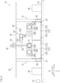
- FIG. 1 is a front elevation view showing an example of the machine tool system 10 according to the first embodiment.
- Fig. 2 is a right-side view of the machine tool system 10 shown in Fig. 1 .
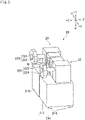
- Fig. 3 is a perspective view showing an example of a machine tool 20 that constitutes the machine tool system 10. It should be noted that illustration of tools 226 described later is omitted in Fig. 3 .
- the machine tool system 10 includes a machine tool 20, a loader (transport apparatus) 30, a workpiece feeder 40, a workpiece collector 50, connecting plates (plates) 60, and a controller 70.
- This machine tool system 10 is installed on a floor surface (mounting surface) FS of a building of a factory or the like.
- the controller 70 controls the machine tool 20 and the loader 30, and the machine tool 20 processes a workpiece W transported by the loader 30.
- the workpiece W is of a cylindrical shape, however, the workpiece W may be of an arbitrary shape and may, for example, be a disc-shaped workpiece.
- the workpiece W may be an elongated rod-shaped workpiece.
- the machine tool 20 includes a first processing apparatus 21, a second processing apparatus 22, and a reversing apparatus 23.
- the machine tool 20 processes the workpiece W transported by the loader 30.
- the first processing apparatus 21 has a bed 210 and a processor 220.
- the bed 210 has a main body 212 and a plurality of leveling bolts (supporters) 214.
- the main body 212 is, for example, of a rectangular parallelepiped shape, and is supported by the plurality of leveling bolts 214 and mounted on the floor surface FS.
- the leveling bolts 214 are attached in the vicinity of four corners on the lower face side of the main body 212, and each thereof comes in contact with the floor surface FS. That is to say, the bed 210 is mounted on the floor surface FS.
- the bed 210 has the processor 220 mounted on an upper face side thereof.
- the processor 220 has a main spindle 222, a turret 224 and a plurality of tools 226.
- the main spindle 222 is supported rotatably around an axis parallel to the Z direction (front-rear direction) and is rotated by a rotation driver not shown in the drawings.
- the main spindle 222 includes a chuck not shown in the drawings capable of gripping the workpiece W at a distal end thereof on the +Z side.
- the chuck has a plurality of gripping claws capable of gripping an end of the workpiece W.
- the main spindle 222 rotates the workpiece W gripped by the chuck around an axis parallel to the Z direction.
- the turret 224 is arranged on the -X side of the main spindle 222.
- the turret 224 is supported rotatably around an axis parallel to the Z direction and is rotated by a rotation driver not shown in the drawings.
- the plurality of tools 226 are, for example, cutting tool bits, end mills, or the like, and are attached respectively to the tool holders of the turret 224 in a detachable manner.
- the plurality of tools 226 may be tools of the same type or tools of different types.
- the first processing apparatus 21 rotates the turret 224 to select a tool 226 for use from the plurality of tools 226 and moves the turret 224 in the X direction (and the Z direction) while axially rotating the workpiece W together with the main spindle 222, to thereby process the workpiece W by means of the tool 226.
- the movement of the turret 224 in the X direction is controlled by the controller 70.
- the position to which the turret 224 is moved in the X direction (left-right direction) regulates the depth of cutting in the workpiece W.
- the second processing apparatus 22 is arranged on the +X direction side with respect to the first processing apparatus 21 and has the same components as those of the first processing apparatus 21.
- the second processing apparatus 22 performs the second processing on the workpiece W that has undergone the first processing performed by the first processing apparatus 21, for example.
- the second processing apparatus 22 differs from the first processing apparatus 21 in that the arrangement of the main spindle 222 and the turret 224 is reversed in the X direction.
- the first processing apparatus 21 and the second processing apparatus 22 each have an individual bed 210, however, the invention is not limited to this form.
- the first processing apparatus 21 and the second processing apparatus 22 may be configured to share one bed 210.
- the processing performed on the workpiece W by the second processing apparatus 22 may differ from the processing performed on the workpiece W by the first processing apparatus 21. Therefore, the tool 226 used by the processor 220 of the second processing apparatus 22 may be different from the tool 226 used by the processor 220 of the first processing apparatus 21.
- the reversing apparatus 23 is arranged on the +Y side (above) of the first processing apparatus 21 and the second processing apparatus 22.
- the reversing apparatus 23 is supported on the bed 210, for example, by a frame or the like not shown in the drawings.
- the reversing apparatus 23 reverses the workpiece W that has undergone the first processing performed by the first processing apparatus 21 in the Z direction before transporting the workpiece W to the second processing apparatus 22.
- the reversing apparatus 23 has chucks 231, 232 and a reverser 234.
- the chucks 231, 232 are arranged in a line along the X direction.
- the chucks 231, 232 each have gripping claws not shown in the drawings and can grip the workpiece W.
- the chuck 232 is provided on the reverser 234.
- the reverser 234 moves the chuck 232 so as to face the chuck 231. After having gripped an end of the workpiece W by means of the chuck 231, the reversing apparatus 23 causes the reverser 234 to move the chuck 232 and causes the chuck 232 to grip the opposite end of the workpiece W.
- the reverser 234 returns the chuck 232 to the original position thereof to thereby reverse the workpiece W in the Z direction.
- Such operations of the reversing apparatus 23 are controlled by the controller 70. It should be noted that the reversing apparatus 23 may be of any configuration. In a case where the workpiece W need not be reversed, the machine tool 20 need not include the reversing apparatus 23.
- the configuration including the first processing apparatus 21 and the second processing apparatus 22 has been described as an example of the machine tool 20, however, the invention is not limited to this configuration.
- the machine tool may include only either one of the first processing apparatus 21 and the second processing apparatus 22.
- the machine tool 20 may include another processing apparatus in addition to the first processing apparatus 21 and the second processing apparatus 22, for example.
- the form in which the tools 226 are attached to the turret 224 has been described as an example, however, the invention is not limited to this form.
- the tools 226 may be held by a comb-shaped tool post instead of the turret 224. In such a case also, by moving in the X direction (left-right direction), the comb-shaped tool post regulates the depth of cutting in the workpiece W performed by the tool 226.
- the loader 30 has two, left and right, legs 31, a beam 32 (see Fig. 2 ), an X-guide 33, an X-slider 34, a Z-slider 35, an elevation rod 36, a loader head 37, and two, left and right, second legs (see Fig. 2 ).
- the loader 30 is a portal-type loader or a gantry loader. The loader 30 transports the workpiece W between the workpiece feeder 40, the first processing apparatus 21, the second processing apparatus 22, and the workpiece collector 50.
- the loader 30 transports the workpiece W from the workpiece feeder 40 to feed it to the first processing apparatus 21; transports the workpiece W processed by the first processing apparatus 21 to the reversing apparatus 23; feeds the workpiece W reversed by the reversing apparatus 23 to the second processing apparatus 23 from the reversing apparatus 23; and transports the workpiece W processed by the second processing apparatus 22 to the workpiece collector 50 from the second processing apparatus 22.
- the two, left and right, legs 31 are arranged on both the left and right sides respectively of the machine tool 20 on the +Z side (front side) of the machine tool 20. These legs 31 are arranged apart from the bed 210 of the machine tool 20.
- Each leg 31 has a leg main body 31A and a leveling bolt 31B.
- the leveling bolt 31B is attached to a lower end of the leg main body 31A and is in contact with the floor surface FS.
- the two, left and right, second legs 131 are arranged on both the left and right sides respectively of the machine tool 20 on the -Z side (rear side) of the machine tool 20. Each of the two second legs 131 is arranged on the rear side (-Z side) of the leg 31.
- Each second leg 131 is arranged apart from the bed 210 of the machine tool 20.
- Each second leg 131 has a leg main body 131A and a leveling bolt 131B.
- the leveling bolt 131B is attached to a lower end of the leg main body 131A and is in contact with the floor surface FS. That is to say, in the present embodiment, the two legs 31 and the two second legs 131 are both in contact with the floor surface FS.
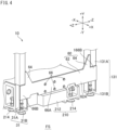
- Fig. 4 is a perspective view of a lower right portion of the machine tool system 10.
- Fig. 5 is a plan view showing an example of an arrangement of the bed 210, the leg 31, and the connecting plate 60. As shown in Fig. 4 and Fig. 5 , the leg 31 is arranged near the leveling bolt 214 of the bed 210. A clearance D is formed between the leg 31 and the bed 210 in the X direction (left-right direction).
- the -X side portion is also configured in a similar manner in which the leg 31 is arranged near the leveling bolt 214 of the bed 210, and a clearance D is formed between the leg 31 and the bed 210 in the X direction (left-right direction).
- the two second legs 131 are arranged in rear (in the -Z direction) of the respective legs 31 and apart from the bed 210 in the -Z direction.
- the beam 32 extends in the Z direction and connects an upper portion of the leg 31 and an upper portion of the second leg 131 to increase the rigidity of the loader 30.
- the X guide 33 extends in the X direction and is fixed to upper ends of the two, left and right, legs 31 (leg main body 31A).
- the X-slider 34 is moved in the X direction (left-right direction) along the X-guide 33 by the driver not shown in the drawings.
- the Z-slider 35 is moved by a driver not shown in the drawings in the Z direction (front-rear direction) along a Z-guide that is included in the X-slider 34 and not shown in the drawings.
- the elevation rod 36 is moved by a driver not shown in the drawings in the Y direction (up-down direction) along an elevation guide that is included in the Z-slider 35 and not shown in the drawings.
- the loader head 37 is provided at a lower end of the elevation rod 36.
- the loader head 37 includes a chuck (gripping claws) not shown in the drawings and is capable of gripping an end of the workpiece W.
- the loader head 37 can switch the orientation of the gripped workpiece W between downward-facing (-Y direction) and side-facing (-Z direction) by means of a swivel joint or the like, for example.
- the workpiece feeder 40 is arranged on the -X side of the machine tool 20. One or more workpieces W that have not been processed by the machine tool 20 are placed on the workpiece feeder 40.
- the workpiece collector 50 is arranged on the +X side of the machine tool 20. One or more workpieces W that have been processed by the machine tool 20 are placed on the workpiece feeder 50.
- the connecting plate 60 connects a lower part of the leg 31 to the bed 210.
- the connecting plate 60 also connects a lower part of the second leg 131 to the bed 210. That is to say, one connecting plate 60 connects the leg 31, the second leg 31, and the bed 210.
- two of the connecting plates 60 are used. Of the two connecting plates 60, one connecting plate 60 is used on the -X side of the first processing apparatus 21 to connect the leg 31, the second leg 131, and the bed 210 of the first processing apparatus 21.
- the other one of the connecting plates 60 is used on the +X side of the second processing apparatus 210 to connect the leg 31, the second leg 131, and the bed 210 of the second processing apparatus 22.
- the two connecting plates 60 are identical or substantially identical, however, may be of different shapes.
- the connecting plate 60 is arranged upright and such that a plate surface 62A is aligned with the Z direction (front-rear direction). That is to say, the connecting plate 60 is arranged in a manner such that the plate surface 62A orthogonal to the plate thickness direction (left-right direction, X direction) thereof includes the Y direction (up-down direction) and the Z direction (front-rear direction).
- the connecting plate 60 has a symmetrical shape as viewed in the X direction and has a main body 62 and two projections 64.
- the main body 62 is of a rectangular shape as viewed from the plate thickness direction thereof.
- the projections 64 are provided to increase the strength of connection between the leg 31 and the second leg 131.
- Each of the two projections 64 is of a triangular shape as viewed from the plate thickness direction thereof.
- the two projections 64 project upward from an upper end face of the main body 62 at both ends in the longitudinal direction of the main body 62 (in the front-rear direction or the Z direction), with their inclined faces opposed to each other, and are provided so as to be shifted toward the center from both ends of the main body 62 in the longitudinal direction.
- the plate thickness and the vertical dimension of the connecting plate 60 can be set arbitrarily.
- the connecting plate 60 is connected to a side face of the bed 210 by a plurality of screws 66 arranged in the Z direction and the Y direction, forming a connection portion 66A.
- the connecting plate 60 is connected to the leg main body 31A of the leg 31 by screws or the like not shown in the drawings to form a connection portion 66B.
- the connecting plate 60 is connected to the leg main body 131A of the second leg 131 by screws or the like not shown in the drawings to form a connection portion 166B.
- the connection portion 66A deviates from the lengthwise center thereof toward the +Z side.
- the distance between the connection portion 66A and the connection portion 66B is shorter than the distance between the connection portion 66A and the connection portion 166B.
- the supporting rigidity of the leg 31 in the X direction (left-right direction) and in the Y direction (up-down direction) is higher than the supporting rigidity of the second leg 131 in the X direction and in the Y direction. Since the leg 31 includes the X-guide 33 at an upper end thereof, it receives much of the load of the loader 30 and is likely to vibrate. Since the supporting rigidity of the legs 31 is high as mentioned above, the loader 30 can be operated stably. It should be noted that the two projections 64 are both arranged between the leg 31 and the second leg 131 as shown in Fig. 4 .
- the connecting plate 60 is a plate composed of metal and is elastically deformable in a direction orthogonal to the plate surface 62A (plate thickness direction). As described above, the connecting plate 60 is arranged upright and such that the plate surface 62A is aligned with the Z direction (front-rear direction). Therefore, the connecting plate 60 has a rigidity higher in the Y direction (up-down direction) and in the Z direction (front-rear direction) than in the X direction (left-right direction). That is to say, the connecting plate 60 has a rigidity capable of receiving the load of the loader 30 in the Y direction (up-down direction) while being allowed to flex (deform elastically) in the X direction (left-right direction). As a result, while receiving the load of the loader 30, if the leg 31 vibrates (oscillates) in the X direction, the connecting plate 60 flexes to thereby suppress transmission of the vibrations in the X direction to the bed 210.
- the controller 70 controls each component of the machine tool 20 and each component of the loader 30. The control of the operation of each component performed by the controller 70 will be described later.
- Fig. 6 to Fig. 9 are diagrams for describing operations of the processing performed on the workpiece W by the machine tool system 10 of the present embodiment and are front elevation views of the machine tool system 10 showing from the start of the processing to the end of the processing. These figures are numbered in chronological order of the processing operations.
- the controller 70 When a worker inputs processing conditions and so forth for the workpiece W into an operation panel (interface) not shown in the drawings, the controller 70 performs control of the machine tool system 10 in accordance with the input information.
- the loader head 37 of the loader 30 descends from above the workpiece feeder 40, grips the workpiece W, and then lifts it (see Fig. 6 ).
- the leg 31 and the second leg 131 vibrate in the up-down direction (Y direction).
- the X-slider 34 moves in the +X direction along the X-guide 33 and stops above the main spindle 222 of the first processing apparatus 21 (see Fig. 7 ).
- the leg 31 and the second leg 131 vibrate in the left-right direction (X direction).
- the loader head 37 descends to a position opposed to the main spindle 222 (overlapping position in the Z direction) as the elevation rod 36 descends, and after changing the orientation of the workpiece W from downward direction to -Z side-facing, the Z-slider 35 moves in the - Z direction to thereby transfer the workpiece W to the main spindle 222 (see Fig. 8 ).
- the first processing apparatus 21 axially rotates the workpiece W held by the main spindle 222 and performs processing on the workpiece W while moving the tool 226 attached to the turret 224 in the +X direction.
- the workpiece W held by the main spindle 222 is transferred to the loader head 37.
- the workpiece W on the loader head 37 is transferred to the chuck 231 of the reversing apparatus 23 by moving the X-slider 34, the Z-slider 35, and the elevation rod 36 (omitted in the drawings).
- the reversing apparatus 23 reverses the workpiece W by transferring the workpiece W from the chuck 231 to the chuck 232.
- the workpiece W is transferred to the main spindle 222 of the second processing apparatus 22 by moving the X-slider 34, the Z-slider 35, and the elevation rod 36 (omitted in the drawings).
- the second processing apparatus 22 axially rotates the workpiece W held by the main spindle 222 and performs processing on the workpiece W while moving the tool 226 attached to the turret 224 in the -X direction.
- the workpiece W held by the main spindle 222 is transferred to the loader head 37.
- the movement of the X-slider 34 causes the leg 31 and the second leg 131 to vibrate in the left-right direction (X direction)
- the ascent and descent of the elevation rod 36 causes the leg 31 and the second leg 131 to vibrate in the up-down direction (Y direction)
- the movement of the Z-slider 35 causes the leg 31 and the second leg 131 to vibrate in the front-rear direction (Z direction).
- the X-slider 34 moves in the +X direction along the X-guide 33 and stops above the workpiece collector 50.
- the movement of the X-slider 34 performed in this manner causes the leg 31 and the second leg 131 to vibrate in the left-right direction (X direction).
- the loader head 37 gripping the workpiece W, which has already undergone the processing descends as the elevation rod 36 descends, and places the workpiece W on the workpiece collector 50 (see Fig. 9 ).
- the ascent and descent of the elevation rod 36 performed in this manner causes the leg 31 and the second leg 131 to vibrate in the up-down direction (Y direction).
- a plurality of workpieces W are processed, and as such processing is performed on the workpieces W, the leg 31 and the second leg 131 vibrate in the left-right direction (X direction) and the up-down directions (Y direction), (Z direction).
- the loader 30 continues to operate even during the processing being performed on the workpiece W by the first processing apparatus 21 and the second processing apparatus 22.
- the bed 210 of the machine tool 20 and the leg 31 and the second leg 131 of the loader 30 are connected to each other by the connecting plate 60.
- the connecting plate 60 is an elastic deformable plate, and the connection portion 66A that connects with the bed 210 and the connection portion 66B that connects with the leg 31 are displaced in the Z direction (front-back direction).
- the connection portion 66A that connects with the bed 210 and the connection portion 166B that connects with the second leg 131 are also displaced in the Z direction (front-back direction).
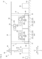
- Fig. 10 is a schematic diagram showing routes over which vibrations generated by the loader 30 are transmitted to the floor surface FS in the machine tool system 10 according to the present embodiment.
- the black arrows denote the propagation direction of vibrations of the legs 31 generated by the loader 30, and the white arrows denote the propagation direction of vibrations generated by the main spindles 222 of the first processing apparatus 21 and the second processing apparatus 22.
- the leg 31 and the bed 210 are connected by the connecting plate 60. Therefore, the relative positions of the machine tool 20 and the loader 30 to each other are unlikely to displace, and thus the workpiece W can be transferred smoothly between the machine tool 20 and the loader 30.
- Some of the vibrations generated by the operation of the loader 30 are transmitted to the bed 210 of the machine tool 20 and transmitted from the leveling bolts 214 of the bed 210 to the floor surface FS. Since the connecting plate 60 has a high rigidity in the up-down direction and the front-rear direction, vibrations of the legs 31 in the up-down direction and the front-rear direction are transmitted from the connecting plate 60 to the floor surface FS through the leveling bolts 214 of the bed 210. The vibrations generated by the main spindle 222 and the tool 226 (turret 224) of the machine tool 20 are transmitted to the floor surface FS through the leveling bolts 214 of the bed 210.
- the connecting plate 60 is elastically deformable in the X direction, and furthermore, the connection portion 66A that connects with the bed 210 and the connection portion 66B that connects with the leg 31 are displaced in the Z direction (front-back direction). Therefore, even when the leg 31 vibrates in the X direction, the elastic deformation of the connecting plate 60 absorbs some of the vibrations and reduces transmission of the vibrations in the X direction to the bed 210.
- the X direction (left-right direction) is a direction in which the depth of cutting in the workpiece W performed by the tool 226 is regulated in the first processing apparatus 21 and the second processing apparatus 22.
- the vibrations of the loader 30 (legs 31) in the X direction are unlikely to be transmitted to the bed 210, variations in the depth of cutting in the workpiece W are small, and a reduction in the accuracy of the processing performed on the workpiece W can be suppressed.
- the elastic deformation of the connecting plate 60 absorbs some of the vibrations and reduces transmission of the vibrations in the X direction to the bed 210. That is to say, in the present embodiment, it is possible to suppress displacement of the relative positions of the machine tool 20 and the loader 30 while suppressing a reduction in the accuracy of the processing performed on the workpiece W.
- the two legs 31 are in contact with the floor surface FS by means of the leveling bolts 31B.
- the two second legs 131 are also in contact with the floor surface FS by means of the leveling bolts 131B.
- some of the vibrations generated by the loader 30 can be transmitted directly to the floor surface FS. Therefore, vibrations to be absorbed by the connecting plate 60 can be reduced. That is to say, by releasing some of the vibrations generated by loader 30 from the legs 31, it is possible to adjust the magnitude of the vibrations transmitted to bed 210.
- the connecting plate 60 has a rigidity more capable of receiving the load of the loader 30 in the Y direction (up-down direction) and in the Z direction (front-rear direction) than in the X direction (left-right direction). Accordingly, when the connecting plate 60 receives the vibrations of the loader 30, even if it deforms elastically in the X direction, it is unlikely to or does not deform in the Y direction and the Z direction. Therefore, in the machine tool system 10 of the present embodiment, transmission of vibrations of the legs 31 (second legs 131) in the X direction to the bed 210 is suppressed, and vibrations of the legs 31 in the Y direction and the Z direction are transmitted to the bed 210 so as to be dampened together with the bed 210.
- vibrations in the Y direction and the Z direction have limited influence on the accuracy of the processing performed on the workpiece W. Therefore, it is possible by suppressing vibrations in the X direction to suppress a reduction in the accuracy of the processing performed on the workpiece W.
- the legs 31 and the second legs 131 are in contact with the floor surface FS by means of the leveling bolts 31B, 131B. That is to say, a majority of the load of the loader 30 can be released from the legs 31 and the second legs 131 to the floor surface FS through the leveling bolts 31B, 131B.
- the burden on the connecting plate 60 in the up-down direction (Y direction) is reduced, and the rigidity of the connecting plate 60 in the up-down direction can be reduced, which reduces the sourcing cost of the connecting plate 60 and prevents deterioration of the connecting plate 60.
- one connecting plate 60 is connected to the leg 31 and the second leg 131. That is to say, one connecting plate 60 is used for both connecting with the leg 31 and connecting with the second leg 131. Therefore, the number of connecting plates 60 used can be reduced compared to the case where the leg 31 and the second leg 131 are connected by separate connecting plates 60, and as a result, the manufacturing cost of the machine tool system 10 can be reduced.
- the configuration is not limited to using one connecting plate 60 to connect the leg 31 and the second leg 131 to the bed 210.
- the leg 31 and the second leg 131 may each be connected to the bed 210 by a separate connecting plate 60.
- FIG. 11 is a perspective view of a lower right portion of the machine tool system 10A according to the second embodiment.
- configurations similar to those of the machine tool system 10 of the first embodiment are assigned with the same reference signs and descriptions thereof are omitted or simplified.
- portions that differ from those of the machine tool system 10 according to the first embodiment will be described.
- the machine tool system 10A differs from the machine tool system 10 of the first embodiment (see Fig.
- the leg 31 is composed of the leg main body 31A only
- the second leg 131 is composed of the leg main body 131A only
- the leg 31 and the second leg 131 do not have the leveling bolts 31B, 131B.
- the leg 31 (leg main body 31A) is arranged directly above or in the vicinity of a position directly above the leveling bolt 214 of the bed 210 and is apart from the bed 210.
- the term "vicinity" means, for example, a position shifted from a position directly above the leveling bolt 214, and as shown in Fig. 5 , the leg main body 31A and the leveling bolt 214 of the bed 210 are adjacent to each other in the X direction while having a clearance D therebetween in the Y direction.
- the leg main body 31A is arranged in the vicinity of a position directly above the leveling bolt 214, however, the invention is not limited to this form.
- the leg 31 (leg main body 31A) may be arranged directly above the leveling bolt 214.
- the connecting plate 60 has a rigidity capable of receiving the load of the loader 30 in the up-down direction.
- the load of the loader 30 is received by the bed 210 through the connecting plate 60. Since each leg 31 is arranged in the vicinity of a position directly above the leveling bolt 214, the bending moment on the bed 210 can be reduced and vibrations transmitted from the leg 31 to the bed 210 through the connecting plate 60 can be released quickly to the floor surface FS compared to the case where the leg 31 is positioned far away from the position directly above the leveling bolt 214. That is to say, the influence of the load of the loader 30 or of the vibrations of the loader 30 on the bed 210 can be reduced. The same applies to the case where the leg 31 is arranged directly above the leveling bolt 214.
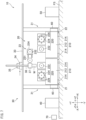
- Fig. 12 is a schematic diagram showing routes over which vibrations generated by the loader 30 are transmitted to the floor surface FS in the machine tool system 10A according to the present embodiment.
- the black arrows denote the propagation direction of vibrations generated by the loader 30, and the white arrows denote the propagation direction of vibrations generated by the main spindles 222 of the first processing apparatus 21 and the second processing apparatus 22.
- Fig. 12 is a schematic diagram showing routes over which vibrations generated by the loader 30 are transmitted to the floor surface FS in the machine tool system 10A according to the present embodiment.
- the black arrows denote the propagation direction of vibrations generated by the loader 30, and the white arrows denote the propagation direction of vibrations generated by the main spindles 222 of the first processing apparatus 21 and the second processing apparatus 22.
- the positions of the machine tool 20 and the loader 30 are unlikely to displace relatively to each other, and the connecting plate 60 reduces transmission of vibrations of the loader 30 (legs 31) in the X direction to the bed 210, which suppresses a reduction in the accuracy of the processing performed on the workpiece W.
- the load of the loader 30 and the vibrations of the leg 31 in the up-down direction and the front-rear direction are transmitted from the connecting plate 60 to the floor surface FS through the leveling bolts 214 of the bed 210. That is to say, in the present embodiment, as with the first embodiment described above, it is possible to suppress displacement of the relative positions of the machine tool 20 and the loader 30 while suppressing a reduction in the accuracy of the processing performed on the workpiece W.
- the distance between the connection portion 66A that connects with the bed 210 and the connection portion 66B that connects with the leg 31 is shorter than the distance between the connection portion 66A and the connection portion 166B that connects with the second leg 131.
- the invention is not limited to this form.
- the distance between the connection portion 66A and the connection portion 66B may be the same as the distance between the connection portion 66A and the connection portion 166B, and for example, the distance between the connection portion 66A and the connection portion 66B may be longer than the distance between the connection portion 66A and the connection portion 166B.
Landscapes
- Engineering & Computer Science (AREA)
- Mechanical Engineering (AREA)
- Machine Tool Units (AREA)
- Auxiliary Devices For Machine Tools (AREA)
- Feeding Of Workpieces (AREA)
- Multi-Process Working Machines And Systems (AREA)
- Turning (AREA)
Abstract
Description
- The present invention relates to a machine tool system.
- There is known a machine tool system that includes a machine tool having a processor to process a workpiece with a tool, and a bed on which the processor is mounted, and a transport apparatus that has a plurality of legs, that transports the workpiece, and that feeds the workpiece to the processor or discharges the workpiece from the processor (see Patent Literature 1). Patent Literature 1 discloses a configuration in which the legs of the transport apparatus are installed on the floor surface independently of the bed of the machine tool as shown in
Fig. 9 . Patent Literature 1 also discloses a configuration in which the legs of the transport apparatus are mounted on the bed of the machine tool as shown inFig. 8 . - [Patent Literature 1]
Japanese Patent No. 5708825 - In the machine tool system shown in
Fig. 9 of Patent Literature 1, the legs of the transport apparatus are installed independently of the bed of the machine tool, and as a result, vibrations occurring at the time of driving the transport apparatus are unlikely to be transmitted to the bed and thus have a limited influence on workpiece processing accuracy. However, since the bed and the legs are independent of each other, the transport apparatus and the machine tool may be displaced relatively to each other, which may hinder transfer of the workpiece between the transport apparatus and the machine tool. In the machine tool system shown inFig. 8 of Patent Literature 1, the legs of the transport apparatus are installed on the bed of the machine tool, and as a result, vibrations occurring at the time of driving the transport apparatus are likely to be transmitted to the bed (processor) and may thus have an increased influence on workpiece processing accuracy, while the transport apparatus and the machine tool are unlikely to be displaced relatively to each other. - An object of the present invention is to provide a machine tool system capable of suppressing displacement of the relative positions of a transport apparatus and a machine tool while suppressing a reduction in workpiece processing accuracy caused by vibrations of the transport apparatus.
- A machine tool system according to an aspect of the present invention comprises: a machine tool having a processor to process a workpiece with a tool, and a bed on which the processor is mounted; a transport apparatus that has two, left and right, legs arranged apart from the bed, that transports the workpiece, and that feeds the workpiece to the processor or discharges the workpiece from the processor; and a plate that connects the bed to the leg and is elastically deformable, wherein the plate is arranged upright and such that a plate surface is aligned with a front-rear direction, and a connection portion of the plate that connects with the bed and a connection portion of the plate that connects with the leg are displaced in a front-back direction.
- The machine tool system of the above aspect suppresses transmission of vibrations of the transport apparatus, which occur when a workpiece is transported or discharged, to the bed (processor), so that it is possible to suppress deterioration of workpiece processing accuracy. Since the legs of the transport apparatus are connected to the bed by a plate, relative displacement between the transport apparatus and the machine tool is regulated, and transfer of a workpiece can thus be performed smoothly between the transport apparatus and the machine tool.
- In the above machine tool system, the processor may have a main spindle that holds and rotates a workpiece, and the tool may move in a left-right direction to thereby regulate the depth of cutting in the workpiece being rotated. With this configuration, it is possible to suppress a reduction in positional accuracy of the cutting depth of the tool with respect to a workpiece. In the above machine tool system, the legs may be arranged in contact with a mounting surface on which the bed is mounted. With this configuration, it is possible to maintain the positional relationship between the legs and the bed in the left-right direction by means of the plate while releasing the load of the transport apparatus to the mounting surface. In the above machine tool system, the legs may be arranged apart in the up-down direction from the mounting surface, on which the bed is mounted. With this configuration, it is possible to suppress transmission of vibrations in the left-right direction to the bed while receiving the load of the transport apparatus by means of the plate. In the above machine tool system, the plate has a rigidity capable of receiving the load of the transport apparatus in the vertical direction. With this configuration, the plate can reliably support the load of the transport apparatus. In the above machine tool system, the bed may have a supporter in contact with the mounting surface, and the leg may be arranged directly above or in the vicinity of a position directly above the supporter and may be apart from the bed. With this configuration, the load of the transport apparatus is applied to a position directly above or to a position in the vicinity of a position directly above the supporter, so that vibrations of the legs can be quickly transmitted to the mounting surface, and furthermore it is possible to suppress a bending moment and the like from occurring in the bed of the machine tool. In the above machine tool system, a second leg may be arranged in rear of each of the two, left and right, legs, and one of the plate may connect the leg and the second leg arranged in the front-rear direction to the bed. With this configuration, it is possible, with one plate, to connect both the leg and the second leg to the bed. In the above machine tool system, a connection portion of the plate that connects with the bed may be provided between a connection portion that connects with the leg and a connection portion that connects with the second leg. With this configuration, it is possible to suppress transmission of vibrations in the left-right direction of the second leg to the bed.
-
-
Fig. 1 is a front elevation view showing an example of a machine tool system according to a first embodiment. -
Fig. 2 is a right-side view of the machine tool system shown inFig. 1 . -
Fig. 3 is a perspective view showing an example of a machine tool. -
Fig. 4 is a perspective view of a lower right portion of the machine tool system according to the first embodiment. -
Fig. 5 is a plan view showing an example of an arrangement of a bed, a leg, and a connecting plate. -
Fig. 6 is a diagram for describing a workpiece processing operation and is a diagram showing a state where a workpiece has been received from a workpiece feeder by a transport apparatus. -
Fig. 7 is a diagram for describing a workpiece processing operation and is a diagram showing a state where the workpiece is being transported in the left-right direction by the transport apparatus. -
Fig. 8 is a diagram for describing a workpiece processing operation and is a diagram showing a state where the workpiece has been transported to a main spindle by the transport apparatus. -
Fig. 9 is a diagram for describing a workpiece processing operation and is a diagram showing a state where the workpiece has been transferred to a workpiece collector by the transport apparatus. -
Fig. 10 is a schematic diagram showing routes over which vibrations generated by the transport apparatus are transmitted to a mounting surface in the machine tool system according to the first embodiment. -
Fig. 11 is a perspective view of a lower right portion of a machine tool system according to a second embodiment. -
Fig. 12 is a schematic diagram showing routes over which vibrations generated by a transport apparatus are transmitted to a mounting surface in the machine tool system according to the second embodiment. - Hereinafter, preferred embodiments will be described. In the drawings referred to in the following description, from the viewpoint of simplification of the description, scale may be changed as necessary such as by illustrating a component or an element in a size that differs from the actual size thereof, or by enlarging or emphasizing it to make a contrast with other components or elements. In the drawings, an XYZ Cartesian coordinate system is used to describe directions of components or elements in each drawing. The X directions indicate left-right directions of a
machine tool system 10, with the +X direction being the right side and the -X direction being the left side when themachine tool system 10 is viewed from the front side. The Y directions indicate up-down directions of themachine tool system 10, with the +Y direction being the upper side and the -Y direction being the lower side. The Z directions are directions orthogonal to the X directions and the Y directions and indicate front-rear directions of themachine tool system 10, with the +Z direction being the front side and the -Z direction being the rear side when themachine tool system 10 is viewed from the front side. - A first embodiment will be described below, with reference to the drawings. Configurations and functions of a
machine tool system 10 according to the present embodiment will be described, with reference toFig. 1 to Fig. 3 .Fig. 1 is a front elevation view showing an example of themachine tool system 10 according to the first embodiment.Fig. 2 is a right-side view of themachine tool system 10 shown inFig. 1 .Fig. 3 is a perspective view showing an example of amachine tool 20 that constitutes themachine tool system 10. It should be noted that illustration oftools 226 described later is omitted inFig. 3 . - As shown in
Fig. 1 andFig. 2 , themachine tool system 10 includes amachine tool 20, a loader (transport apparatus) 30, aworkpiece feeder 40, aworkpiece collector 50, connecting plates (plates) 60, and acontroller 70. Thismachine tool system 10 is installed on a floor surface (mounting surface) FS of a building of a factory or the like. In themachine tool system 10, thecontroller 70 controls themachine tool 20 and theloader 30, and themachine tool 20 processes a workpiece W transported by theloader 30. In the present embodiment, the workpiece W is of a cylindrical shape, however, the workpiece W may be of an arbitrary shape and may, for example, be a disc-shaped workpiece. The workpiece W may be an elongated rod-shaped workpiece. - As shown in
Fig. 1 andFig. 2 , themachine tool 20 includes afirst processing apparatus 21, asecond processing apparatus 22, and a reversingapparatus 23. Themachine tool 20 processes the workpiece W transported by theloader 30. As shown inFig. 1 andFig. 3 , thefirst processing apparatus 21 has abed 210 and aprocessor 220. Thefirst processing apparatus 21, for example, performs the first processing on the workpiece W by means of theprocessor 220. - The
bed 210 has amain body 212 and a plurality of leveling bolts (supporters) 214. Themain body 212 is, for example, of a rectangular parallelepiped shape, and is supported by the plurality of levelingbolts 214 and mounted on the floor surface FS. The levelingbolts 214 are attached in the vicinity of four corners on the lower face side of themain body 212, and each thereof comes in contact with the floor surface FS. That is to say, thebed 210 is mounted on the floor surface FS. - The
bed 210 has theprocessor 220 mounted on an upper face side thereof. Theprocessor 220 has amain spindle 222, aturret 224 and a plurality oftools 226. Themain spindle 222 is supported rotatably around an axis parallel to the Z direction (front-rear direction) and is rotated by a rotation driver not shown in the drawings. Themain spindle 222 includes a chuck not shown in the drawings capable of gripping the workpiece W at a distal end thereof on the +Z side. The chuck has a plurality of gripping claws capable of gripping an end of the workpiece W. Themain spindle 222 rotates the workpiece W gripped by the chuck around an axis parallel to the Z direction. Theturret 224 is arranged on the -X side of themain spindle 222. Theturret 224 is supported rotatably around an axis parallel to the Z direction and is rotated by a rotation driver not shown in the drawings. On an outer peripheral surface ofturret 224 there are provided a plurality of tool holders to hold thetools 226. The plurality oftools 226 are, for example, cutting tool bits, end mills, or the like, and are attached respectively to the tool holders of theturret 224 in a detachable manner. The plurality oftools 226 may be tools of the same type or tools of different types. - The
first processing apparatus 21 rotates theturret 224 to select atool 226 for use from the plurality oftools 226 and moves theturret 224 in the X direction (and the Z direction) while axially rotating the workpiece W together with themain spindle 222, to thereby process the workpiece W by means of thetool 226. In such a case, the movement of theturret 224 in the X direction is controlled by thecontroller 70. The position to which theturret 224 is moved in the X direction (left-right direction) regulates the depth of cutting in the workpiece W. - As shown in
Fig. 1 andFig. 3 , thesecond processing apparatus 22 is arranged on the +X direction side with respect to thefirst processing apparatus 21 and has the same components as those of thefirst processing apparatus 21. Thesecond processing apparatus 22 performs the second processing on the workpiece W that has undergone the first processing performed by thefirst processing apparatus 21, for example. Thesecond processing apparatus 22 differs from thefirst processing apparatus 21 in that the arrangement of themain spindle 222 and theturret 224 is reversed in the X direction. Thefirst processing apparatus 21 and thesecond processing apparatus 22 each have anindividual bed 210, however, the invention is not limited to this form. For example, thefirst processing apparatus 21 and thesecond processing apparatus 22 may be configured to share onebed 210. The processing performed on the workpiece W by thesecond processing apparatus 22 may differ from the processing performed on the workpiece W by thefirst processing apparatus 21. Therefore, thetool 226 used by theprocessor 220 of thesecond processing apparatus 22 may be different from thetool 226 used by theprocessor 220 of thefirst processing apparatus 21. - As shown in
Fig. 1 andFig. 2 , the reversingapparatus 23 is arranged on the +Y side (above) of thefirst processing apparatus 21 and thesecond processing apparatus 22. The reversingapparatus 23 is supported on thebed 210, for example, by a frame or the like not shown in the drawings. The reversingapparatus 23 reverses the workpiece W that has undergone the first processing performed by thefirst processing apparatus 21 in the Z direction before transporting the workpiece W to thesecond processing apparatus 22. - As shown in
Fig. 1 andFig. 2 , the reversingapparatus 23 haschucks reverser 234. Thechucks chucks chuck 232 is provided on thereverser 234. Thereverser 234 moves thechuck 232 so as to face thechuck 231. After having gripped an end of the workpiece W by means of thechuck 231, the reversingapparatus 23 causes thereverser 234 to move thechuck 232 and causes thechuck 232 to grip the opposite end of the workpiece W. Next, after the grip of the workpiece W by means of thechuck 231 has been released, thereverser 234 returns thechuck 232 to the original position thereof to thereby reverse the workpiece W in the Z direction. Such operations of the reversingapparatus 23 are controlled by thecontroller 70. It should be noted that the reversingapparatus 23 may be of any configuration. In a case where the workpiece W need not be reversed, themachine tool 20 need not include the reversingapparatus 23. - In the present embodiment, the configuration including the
first processing apparatus 21 and thesecond processing apparatus 22 has been described as an example of themachine tool 20, however, the invention is not limited to this configuration. For example, the machine tool may include only either one of thefirst processing apparatus 21 and thesecond processing apparatus 22. Also, themachine tool 20 may include another processing apparatus in addition to thefirst processing apparatus 21 and thesecond processing apparatus 22, for example. In the present embodiment, the form in which thetools 226 are attached to theturret 224 has been described as an example, however, the invention is not limited to this form. For example, thetools 226 may be held by a comb-shaped tool post instead of theturret 224. In such a case also, by moving in the X direction (left-right direction), the comb-shaped tool post regulates the depth of cutting in the workpiece W performed by thetool 226. - The
loader 30 has two, left and right,legs 31, a beam 32 (seeFig. 2 ), an X-guide 33, an X-slider 34, a Z-slider 35, anelevation rod 36, aloader head 37, and two, left and right, second legs (seeFig. 2 ). Theloader 30 is a portal-type loader or a gantry loader. Theloader 30 transports the workpiece W between theworkpiece feeder 40, thefirst processing apparatus 21, thesecond processing apparatus 22, and theworkpiece collector 50. For example, the loader 30: transports the workpiece W from theworkpiece feeder 40 to feed it to thefirst processing apparatus 21; transports the workpiece W processed by thefirst processing apparatus 21 to the reversingapparatus 23; feeds the workpiece W reversed by the reversingapparatus 23 to thesecond processing apparatus 23 from the reversingapparatus 23; and transports the workpiece W processed by thesecond processing apparatus 22 to theworkpiece collector 50 from thesecond processing apparatus 22. - The two, left and right,
legs 31 are arranged on both the left and right sides respectively of themachine tool 20 on the +Z side (front side) of themachine tool 20. Theselegs 31 are arranged apart from thebed 210 of themachine tool 20. Eachleg 31 has a legmain body 31A and aleveling bolt 31B. The levelingbolt 31B is attached to a lower end of the legmain body 31A and is in contact with the floor surface FS. The two, left and right,second legs 131 are arranged on both the left and right sides respectively of themachine tool 20 on the -Z side (rear side) of themachine tool 20. Each of the twosecond legs 131 is arranged on the rear side (-Z side) of theleg 31. Thesesecond legs 131 are arranged apart from thebed 210 of themachine tool 20. Eachsecond leg 131 has a legmain body 131A and aleveling bolt 131B. The levelingbolt 131B is attached to a lower end of the legmain body 131A and is in contact with the floor surface FS. That is to say, in the present embodiment, the twolegs 31 and the twosecond legs 131 are both in contact with the floor surface FS. -
Fig. 4 is a perspective view of a lower right portion of themachine tool system 10.Fig. 5 is a plan view showing an example of an arrangement of thebed 210, theleg 31, and the connectingplate 60. As shown inFig. 4 andFig. 5 , theleg 31 is arranged near the levelingbolt 214 of thebed 210. A clearance D is formed between theleg 31 and thebed 210 in the X direction (left-right direction).Fig. 4 andFig. 5 only show the +X side portion of themachine tool system 10, however, the -X side portion is also configured in a similar manner in which theleg 31 is arranged near the levelingbolt 214 of thebed 210, and a clearance D is formed between theleg 31 and thebed 210 in the X direction (left-right direction). The twosecond legs 131 are arranged in rear (in the -Z direction) of therespective legs 31 and apart from thebed 210 in the -Z direction. - As shown in
Fig. 2 , thebeam 32 extends in the Z direction and connects an upper portion of theleg 31 and an upper portion of thesecond leg 131 to increase the rigidity of theloader 30. As shown inFig. 1 ,Fig. 2 and so forth, theX guide 33 extends in the X direction and is fixed to upper ends of the two, left and right, legs 31 (legmain body 31A). The X-slider 34 is moved in the X direction (left-right direction) along the X-guide 33 by the driver not shown in the drawings. The Z-slider 35 is moved by a driver not shown in the drawings in the Z direction (front-rear direction) along a Z-guide that is included in the X-slider 34 and not shown in the drawings. Theelevation rod 36 is moved by a driver not shown in the drawings in the Y direction (up-down direction) along an elevation guide that is included in the Z-slider 35 and not shown in the drawings. Theloader head 37 is provided at a lower end of theelevation rod 36. Theloader head 37 includes a chuck (gripping claws) not shown in the drawings and is capable of gripping an end of the workpiece W. Theloader head 37 can switch the orientation of the gripped workpiece W between downward-facing (-Y direction) and side-facing (-Z direction) by means of a swivel joint or the like, for example. - The
workpiece feeder 40 is arranged on the -X side of themachine tool 20. One or more workpieces W that have not been processed by themachine tool 20 are placed on theworkpiece feeder 40. Theworkpiece collector 50 is arranged on the +X side of themachine tool 20. One or more workpieces W that have been processed by themachine tool 20 are placed on theworkpiece feeder 50. - As shown in
Fig. 1 andFig. 2 , the connectingplate 60 connects a lower part of theleg 31 to thebed 210. The connectingplate 60 also connects a lower part of thesecond leg 131 to thebed 210. That is to say, one connectingplate 60 connects theleg 31, thesecond leg 31, and thebed 210. In themachine tool system 10 of the present embodiment, two of the connectingplates 60 are used. Of the two connectingplates 60, one connectingplate 60 is used on the -X side of thefirst processing apparatus 21 to connect theleg 31, thesecond leg 131, and thebed 210 of thefirst processing apparatus 21. The other one of the connectingplates 60 is used on the +X side of thesecond processing apparatus 210 to connect theleg 31, thesecond leg 131, and thebed 210 of thesecond processing apparatus 22. The two connectingplates 60 are identical or substantially identical, however, may be of different shapes. - As shown in
Fig. 1 ,Fig. 2 ,Fig. 4 andFig. 5 , the connectingplate 60 is arranged upright and such that aplate surface 62A is aligned with the Z direction (front-rear direction). That is to say, the connectingplate 60 is arranged in a manner such that theplate surface 62A orthogonal to the plate thickness direction (left-right direction, X direction) thereof includes the Y direction (up-down direction) and the Z direction (front-rear direction). As shown inFig. 2 andFig. 4 , the connectingplate 60 has a symmetrical shape as viewed in the X direction and has amain body 62 and twoprojections 64. Themain body 62 is of a rectangular shape as viewed from the plate thickness direction thereof. Theprojections 64 are provided to increase the strength of connection between theleg 31 and thesecond leg 131. Each of the twoprojections 64 is of a triangular shape as viewed from the plate thickness direction thereof. The twoprojections 64 project upward from an upper end face of themain body 62 at both ends in the longitudinal direction of the main body 62 (in the front-rear direction or the Z direction), with their inclined faces opposed to each other, and are provided so as to be shifted toward the center from both ends of themain body 62 in the longitudinal direction. The plate thickness and the vertical dimension of the connectingplate 60 can be set arbitrarily. - As shown in
Fig. 4 andFig. 5 , the connectingplate 60 is connected to a side face of thebed 210 by a plurality ofscrews 66 arranged in the Z direction and the Y direction, forming aconnection portion 66A. The connectingplate 60 is connected to the legmain body 31A of theleg 31 by screws or the like not shown in the drawings to form aconnection portion 66B. The connectingplate 60 is connected to the legmain body 131A of thesecond leg 131 by screws or the like not shown in the drawings to form aconnection portion 166B. In the longitudinal direction of themain body 62, theconnection portion 66A deviates from the lengthwise center thereof toward the +Z side. That is to say, in the Z direction (front-rear direction), the distance between theconnection portion 66A and theconnection portion 66B is shorter than the distance between theconnection portion 66A and theconnection portion 166B. As a result, the supporting rigidity of theleg 31 in the X direction (left-right direction) and in the Y direction (up-down direction) is higher than the supporting rigidity of thesecond leg 131 in the X direction and in the Y direction. Since theleg 31 includes the X-guide 33 at an upper end thereof, it receives much of the load of theloader 30 and is likely to vibrate. Since the supporting rigidity of thelegs 31 is high as mentioned above, theloader 30 can be operated stably. It should be noted that the twoprojections 64 are both arranged between theleg 31 and thesecond leg 131 as shown inFig. 4 . - As an example, the connecting
plate 60 is a plate composed of metal and is elastically deformable in a direction orthogonal to theplate surface 62A (plate thickness direction). As described above, the connectingplate 60 is arranged upright and such that theplate surface 62A is aligned with the Z direction (front-rear direction). Therefore, the connectingplate 60 has a rigidity higher in the Y direction (up-down direction) and in the Z direction (front-rear direction) than in the X direction (left-right direction). That is to say, the connectingplate 60 has a rigidity capable of receiving the load of theloader 30 in the Y direction (up-down direction) while being allowed to flex (deform elastically) in the X direction (left-right direction). As a result, while receiving the load of theloader 30, if theleg 31 vibrates (oscillates) in the X direction, the connectingplate 60 flexes to thereby suppress transmission of the vibrations in the X direction to thebed 210. - The
controller 70 controls each component of themachine tool 20 and each component of theloader 30. The control of the operation of each component performed by thecontroller 70 will be described later. - Next, operations of the processing performed on the workpiece W by the
machine tool system 10 according to the present embodiment will be described, with reference toFig. 6 to Fig. 9. Fig. 6 to Fig. 9 are diagrams for describing operations of the processing performed on the workpiece W by themachine tool system 10 of the present embodiment and are front elevation views of themachine tool system 10 showing from the start of the processing to the end of the processing. These figures are numbered in chronological order of the processing operations. - When a worker inputs processing conditions and so forth for the workpiece W into an operation panel (interface) not shown in the drawings, the
controller 70 performs control of themachine tool system 10 in accordance with the input information. First, as shown inFig. 6 , at the start of the processing, theloader head 37 of theloader 30 descends from above theworkpiece feeder 40, grips the workpiece W, and then lifts it (seeFig. 6 ). As theloader head 37 ascends or descends, theleg 31 and thesecond leg 131 vibrate in the up-down direction (Y direction). Next, after theloader head 37 has ascended, the X-slider 34 moves in the +X direction along the X-guide 33 and stops above themain spindle 222 of the first processing apparatus 21 (seeFig. 7 ). As the X-slider 34 moves and stops in this manner, theleg 31 and thesecond leg 131 vibrate in the left-right direction (X direction). Next, theloader head 37 descends to a position opposed to the main spindle 222 (overlapping position in the Z direction) as theelevation rod 36 descends, and after changing the orientation of the workpiece W from downward direction to -Z side-facing, the Z-slider 35 moves in the - Z direction to thereby transfer the workpiece W to the main spindle 222 (seeFig. 8 ). - The
first processing apparatus 21 axially rotates the workpiece W held by themain spindle 222 and performs processing on the workpiece W while moving thetool 226 attached to theturret 224 in the +X direction. When the processing has ended, the workpiece W held by themain spindle 222 is transferred to theloader head 37. The workpiece W on theloader head 37 is transferred to thechuck 231 of the reversingapparatus 23 by moving the X-slider 34, the Z-slider 35, and the elevation rod 36 (omitted in the drawings). The reversingapparatus 23 reverses the workpiece W by transferring the workpiece W from thechuck 231 to thechuck 232. After theloader head 37 has received the reversed workpiece W, the workpiece W is transferred to themain spindle 222 of thesecond processing apparatus 22 by moving the X-slider 34, the Z-slider 35, and the elevation rod 36 (omitted in the drawings). - The
second processing apparatus 22 axially rotates the workpiece W held by themain spindle 222 and performs processing on the workpiece W while moving thetool 226 attached to theturret 224 in the -X direction. When the processing has ended, the workpiece W held by themain spindle 222 is transferred to theloader head 37. During the transfer of the workpiece W between themain spindle 222 and the reversingapparatus 23, the movement of the X-slider 34 causes theleg 31 and thesecond leg 131 to vibrate in the left-right direction (X direction), the ascent and descent of theelevation rod 36 causes theleg 31 and thesecond leg 131 to vibrate in the up-down direction (Y direction), and the movement of the Z-slider 35 causes theleg 31 and thesecond leg 131 to vibrate in the front-rear direction (Z direction). - Next, the X-slider 34 moves in the +X direction along the X-guide 33 and stops above the
workpiece collector 50. The movement of the X-slider 34 performed in this manner causes theleg 31 and thesecond leg 131 to vibrate in the left-right direction (X direction). Next, theloader head 37 gripping the workpiece W, which has already undergone the processing, descends as theelevation rod 36 descends, and places the workpiece W on the workpiece collector 50 (seeFig. 9 ). The ascent and descent of theelevation rod 36 performed in this manner causes theleg 31 and thesecond leg 131 to vibrate in the up-down direction (Y direction). Through the operations exemplified above, the processing of the workpiece W according to the present embodiment is completed. By repeating the above operations, a plurality of workpieces W are processed, and as such processing is performed on the workpieces W, theleg 31 and thesecond leg 131 vibrate in the left-right direction (X direction) and the up-down directions (Y direction), (Z direction). Theloader 30 continues to operate even during the processing being performed on the workpiece W by thefirst processing apparatus 21 and thesecond processing apparatus 22. - Next, actions of the first embodiment will be described, with reference to the drawings. As mentioned above, the
bed 210 of themachine tool 20 and theleg 31 and thesecond leg 131 of theloader 30 are connected to each other by the connectingplate 60. The connectingplate 60 is an elastic deformable plate, and theconnection portion 66A that connects with thebed 210 and theconnection portion 66B that connects with theleg 31 are displaced in the Z direction (front-back direction). Theconnection portion 66A that connects with thebed 210 and theconnection portion 166B that connects with thesecond leg 131 are also displaced in the Z direction (front-back direction). -
Fig. 10 is a schematic diagram showing routes over which vibrations generated by theloader 30 are transmitted to the floor surface FS in themachine tool system 10 according to the present embodiment. The black arrows denote the propagation direction of vibrations of thelegs 31 generated by theloader 30, and the white arrows denote the propagation direction of vibrations generated by themain spindles 222 of thefirst processing apparatus 21 and thesecond processing apparatus 22. As shown inFig. 10 , in themachine tool system 10 of the present embodiment, theleg 31 and thebed 210 are connected by the connectingplate 60. Therefore, the relative positions of themachine tool 20 and theloader 30 to each other are unlikely to displace, and thus the workpiece W can be transferred smoothly between themachine tool 20 and theloader 30. Some of the vibrations generated by the operation of theloader 30 are transmitted to thebed 210 of themachine tool 20 and transmitted from the levelingbolts 214 of thebed 210 to the floor surface FS. Since the connectingplate 60 has a high rigidity in the up-down direction and the front-rear direction, vibrations of thelegs 31 in the up-down direction and the front-rear direction are transmitted from the connectingplate 60 to the floor surface FS through the levelingbolts 214 of thebed 210. The vibrations generated by themain spindle 222 and the tool 226 (turret 224) of themachine tool 20 are transmitted to the floor surface FS through the levelingbolts 214 of thebed 210. - The connecting
plate 60 is elastically deformable in the X direction, and furthermore, theconnection portion 66A that connects with thebed 210 and theconnection portion 66B that connects with theleg 31 are displaced in the Z direction (front-back direction). Therefore, even when theleg 31 vibrates in the X direction, the elastic deformation of the connectingplate 60 absorbs some of the vibrations and reduces transmission of the vibrations in the X direction to thebed 210. The X direction (left-right direction) is a direction in which the depth of cutting in the workpiece W performed by thetool 226 is regulated in thefirst processing apparatus 21 and thesecond processing apparatus 22. Therefore, since the vibrations of the loader 30 (legs 31) in the X direction are unlikely to be transmitted to thebed 210, variations in the depth of cutting in the workpiece W are small, and a reduction in the accuracy of the processing performed on the workpiece W can be suppressed. Although not illustrated inFig. 10 , similarly, even when thesecond leg 131 vibrates in the X direction, the elastic deformation of the connectingplate 60 absorbs some of the vibrations and reduces transmission of the vibrations in the X direction to thebed 210. That is to say, in the present embodiment, it is possible to suppress displacement of the relative positions of themachine tool 20 and theloader 30 while suppressing a reduction in the accuracy of the processing performed on the workpiece W. - As shown in
Fig. 1 andFig. 2 , in themachine tool system 10 of the present embodiment, the twolegs 31 are in contact with the floor surface FS by means of the levelingbolts 31B. The twosecond legs 131 are also in contact with the floor surface FS by means of the levelingbolts 131B. As a result, some of the vibrations generated by theloader 30 can be transmitted directly to the floor surface FS. Therefore, vibrations to be absorbed by the connectingplate 60 can be reduced. That is to say, by releasing some of the vibrations generated byloader 30 from thelegs 31, it is possible to adjust the magnitude of the vibrations transmitted tobed 210. - The connecting
plate 60 has a rigidity more capable of receiving the load of theloader 30 in the Y direction (up-down direction) and in the Z direction (front-rear direction) than in the X direction (left-right direction). Accordingly, when the connectingplate 60 receives the vibrations of theloader 30, even if it deforms elastically in the X direction, it is unlikely to or does not deform in the Y direction and the Z direction. Therefore, in themachine tool system 10 of the present embodiment, transmission of vibrations of the legs 31 (second legs 131) in the X direction to thebed 210 is suppressed, and vibrations of thelegs 31 in the Y direction and the Z direction are transmitted to thebed 210 so as to be dampened together with thebed 210. In many cases, vibrations in the Y direction and the Z direction have limited influence on the accuracy of the processing performed on the workpiece W. Therefore, it is possible by suppressing vibrations in the X direction to suppress a reduction in the accuracy of the processing performed on the workpiece W. - In the present embodiment, the
legs 31 and thesecond legs 131 are in contact with the floor surface FS by means of the levelingbolts loader 30 can be released from thelegs 31 and thesecond legs 131 to the floor surface FS through the levelingbolts plate 60 in the up-down direction (Y direction) is reduced, and the rigidity of the connectingplate 60 in the up-down direction can be reduced, which reduces the sourcing cost of the connectingplate 60 and prevents deterioration of the connectingplate 60. - In the present embodiment, as shown in
Fig. 2 ,Fig. 4 andFig. 5 , one connectingplate 60 is connected to theleg 31 and thesecond leg 131. That is to say, one connectingplate 60 is used for both connecting with theleg 31 and connecting with thesecond leg 131. Therefore, the number of connectingplates 60 used can be reduced compared to the case where theleg 31 and thesecond leg 131 are connected by separate connectingplates 60, and as a result, the manufacturing cost of themachine tool system 10 can be reduced. In the present embodiment, the configuration is not limited to using one connectingplate 60 to connect theleg 31 and thesecond leg 131 to thebed 210. For example, theleg 31 and thesecond leg 131 may each be connected to thebed 210 by a separate connectingplate 60. - Next, a
machine tool system 10A according to a second embodiment will be described, with reference toFig. 11 andFig. 12 .Fig. 11 is a perspective view of a lower right portion of themachine tool system 10A according to the second embodiment. In the following description, configurations similar to those of themachine tool system 10 of the first embodiment are assigned with the same reference signs and descriptions thereof are omitted or simplified. In the following description, portions that differ from those of themachine tool system 10 according to the first embodiment will be described. As shown inFig. 11 , themachine tool system 10A differs from themachine tool system 10 of the first embodiment (seeFig. 1 and so forth) in that the twolegs 31 and the twosecond legs 131 are arranged apart in the Y direction (up-down direction) from the floor surface FS. That is to say, in themachine tool system 10A, theleg 31 is composed of the legmain body 31A only, thesecond leg 131 is composed of the legmain body 131A only, and theleg 31 and thesecond leg 131 do not have the levelingbolts - The leg 31 (leg
main body 31A) is arranged directly above or in the vicinity of a position directly above the levelingbolt 214 of thebed 210 and is apart from thebed 210. Here, the term "vicinity" means, for example, a position shifted from a position directly above the levelingbolt 214, and as shown inFig. 5 , the legmain body 31A and theleveling bolt 214 of thebed 210 are adjacent to each other in the X direction while having a clearance D therebetween in the Y direction. In the present embodiment, the legmain body 31A is arranged in the vicinity of a position directly above the levelingbolt 214, however, the invention is not limited to this form. For example, the leg 31 (legmain body 31A) may be arranged directly above the levelingbolt 214. - The connecting
plate 60 has a rigidity capable of receiving the load of theloader 30 in the up-down direction. In the present embodiment, the load of theloader 30 is received by thebed 210 through the connectingplate 60. Since eachleg 31 is arranged in the vicinity of a position directly above the levelingbolt 214, the bending moment on thebed 210 can be reduced and vibrations transmitted from theleg 31 to thebed 210 through the connectingplate 60 can be released quickly to the floor surface FS compared to the case where theleg 31 is positioned far away from the position directly above the levelingbolt 214. That is to say, the influence of the load of theloader 30 or of the vibrations of theloader 30 on thebed 210 can be reduced. The same applies to the case where theleg 31 is arranged directly above the levelingbolt 214. - Next, actions of the present embodiment will be described, with reference to
Fig. 12. Fig. 12 is a schematic diagram showing routes over which vibrations generated by theloader 30 are transmitted to the floor surface FS in themachine tool system 10A according to the present embodiment. The black arrows denote the propagation direction of vibrations generated by theloader 30, and the white arrows denote the propagation direction of vibrations generated by themain spindles 222 of thefirst processing apparatus 21 and thesecond processing apparatus 22. As shown inFig. 12 , in themachine tool system 10A of the present embodiment, the positions of themachine tool 20 and theloader 30 are unlikely to displace relatively to each other, and the connectingplate 60 reduces transmission of vibrations of the loader 30 (legs 31) in the X direction to thebed 210, which suppresses a reduction in the accuracy of the processing performed on the workpiece W. The load of theloader 30 and the vibrations of theleg 31 in the up-down direction and the front-rear direction are transmitted from the connectingplate 60 to the floor surface FS through the levelingbolts 214 of thebed 210. That is to say, in the present embodiment, as with the first embodiment described above, it is possible to suppress displacement of the relative positions of themachine tool 20 and theloader 30 while suppressing a reduction in the accuracy of the processing performed on the workpiece W. - The embodiments of the present invention have been described above. However, the technical scope of the present invention is not limited to the forms described in the above embodiments. For example, the present invention may omit some of the components described in the above embodiments. Also, one or more of the components described in the above embodiments may be combined where appropriate. The contents of all documents cited in the detailed description of the present invention are incorporated herein by reference to the extent permitted by law.
- Furthermore, in the embodiments described above, the distance between the
connection portion 66A that connects with thebed 210 and theconnection portion 66B that connects with theleg 31 is shorter than the distance between theconnection portion 66A and theconnection portion 166B that connects with thesecond leg 131. However, the invention is not limited to this form. For example, the distance between theconnection portion 66A and theconnection portion 66B may be the same as the distance between theconnection portion 66A and theconnection portion 166B, and for example, the distance between theconnection portion 66A and theconnection portion 66B may be longer than the distance between theconnection portion 66A and theconnection portion 166B. - One or more of the requirements described in the above embodiments may be omitted in some cases. One or more of the requirements described in the above embodiments may be combined where appropriate. The contents of
Japanese Patent Application No. 2020-092386 -
- 10:
- Machine tool system
- 10A:
- Machine tool system
- 20:
- Machine tool
- 21:
- First processing apparatus
- 22:
- Second processing apparatus
- 30:
- Loader (transport apparatus)
- 31:
- Leg
- 131:
- Second leg
- 60:
- Connecting plate (plate)
- 62:
- Plate surface
- 66A:
- Connection portion
- 66B:
- Connection portion
- 210:
- Bed
- 214:
- Leveling bolt (supporter)
- 220:
- Processor
- 222:
- Main spindle
- 226:
- Tool
- FS:
- Floor surface (mounting surface)
- W:
- Workpiece
Claims (8)
- A machine tool system comprising:a machine tool having a processor to process a workpiece with a tool, and a bed on which the processor is mounted;a transport apparatus that has two, left and right, legs arranged apart from the bed, that transports the workpiece, and that feeds the workpiece to the processor or discharges the workpiece from the processor; anda plate that connects the bed to the leg and is elastically deformable,wherein the plate is arranged upright and such that a plate surface is aligned with a front-rear direction, andwherein a connection portion of the plate that connects with the bed and a connection portion of the plate that connects with the leg are displaced in a front-back direction.
- The machine tool system according to claim 1,wherein the processor has a main spindle that holds and rotates a workpiece, andwherein the tool moves in a left-right direction to thereby regulate a depth of cutting in the workpiece being rotated.
- The machine tool system according to claim 1 or 2, wherein the legs are arranged in contact with a mounting surface on which the bed is mounted.
- The machine tool system according to claim 1 or 2, wherein the legs are arranged apart in an up-down direction from a mounting surface on which the bed is mounted.
- The machine tool system according to claim 4, wherein the plate has a rigidity capable of receiving a load of the transport apparatus in a vertical direction.
- The machine tool system according to claim 4 or 5,wherein the bed has a supporter in contact with the mounting surface, andthe leg is arranged directly above or in the vicinity of a position directly above the supporter and is apart from the bed.
- The machine tool system according to any one of claims 1 to 6,wherein a second leg is arranged in rear of each of the two, left and right, legs, andwherein one of the plate connects the leg and the second leg arranged in the front-rear direction to the bed.
- The machine tool system according to claim 7, wherein a connection portion of the plate that connects with the bed is provided between a connection portion that connects with the leg and a connection portion that connects with the second leg.
Applications Claiming Priority (2)
| Application Number | Priority Date | Filing Date | Title |
|---|---|---|---|
| JP2020086628 | 2020-05-18 | ||
| PCT/JP2021/015429 WO2021235142A1 (en) | 2020-05-18 | 2021-04-14 | Machine tool system |
Publications (3)
| Publication Number | Publication Date |
|---|---|
| EP4155022A1 true EP4155022A1 (en) | 2023-03-29 |
| EP4155022A4 EP4155022A4 (en) | 2024-05-22 |
| EP4155022B1 EP4155022B1 (en) | 2025-03-12 |
Family
ID=78707773
Family Applications (1)
| Application Number | Title | Priority Date | Filing Date |
|---|---|---|---|
| EP21808744.3A Active EP4155022B1 (en) | 2020-05-18 | 2021-04-14 | Machine tool system |
Country Status (6)
| Country | Link |
|---|---|
| US (1) | US12311490B2 (en) |
| EP (1) | EP4155022B1 (en) |
| JP (1) | JP7371774B2 (en) |
| KR (1) | KR102743825B1 (en) |
| CN (1) | CN115605317B (en) |
| WO (1) | WO2021235142A1 (en) |
Families Citing this family (4)
| Publication number | Priority date | Publication date | Assignee | Title |
|---|---|---|---|---|
| JP7774642B2 (en) * | 2021-12-14 | 2025-11-21 | 株式会社Fuji | machine tools |
| JP2023161243A (en) * | 2022-04-25 | 2023-11-07 | 株式会社Fuji | Machine Tools |
| JP2024029974A (en) * | 2022-08-23 | 2024-03-07 | 株式会社Fuji | Machine tool with gantry loader |
| CN121132367B (en) * | 2025-11-18 | 2026-02-27 | 沈阳精锐数控机床有限公司 | Feeding mechanism for machine tool spindles that are not rotating. |
Family Cites Families (16)
| Publication number | Priority date | Publication date | Assignee | Title |
|---|---|---|---|---|
| JPH071213Y2 (en) * | 1988-02-17 | 1995-01-18 | 本田技研工業株式会社 | Machine tool chuck device |
| US5920973A (en) * | 1997-03-09 | 1999-07-13 | Electro Scientific Industries, Inc. | Hole forming system with multiple spindles per station |
| JP4400011B2 (en) | 2001-07-27 | 2010-01-20 | 村田機械株式会社 | Machine Tools |
| KR100450427B1 (en) * | 2001-12-31 | 2004-09-30 | 대우종합기계 주식회사 | Manufacturing machine for cutting work |
| CN201002184Y (en) | 2006-12-08 | 2008-01-09 | 天水星火机床有限责任公司 | Machine tool supporting piece |
| JP5161468B2 (en) * | 2007-03-13 | 2013-03-13 | ホーコス株式会社 | Machine Tools |
| WO2010110030A1 (en) | 2009-03-27 | 2010-09-30 | 村田機械株式会社 | Two-axis machine tool |
| JP5295855B2 (en) * | 2009-04-28 | 2013-09-18 | 住友重機械工業株式会社 | Reaction force processing mechanism |
| JP2011245563A (en) * | 2010-05-24 | 2011-12-08 | Murata Machinery Ltd | Machine tool |
| EP2689889B1 (en) * | 2011-03-24 | 2015-07-22 | Murata Machinery, Ltd. | Machine tool system |
| EP2796239A4 (en) | 2011-12-22 | 2015-07-29 | Murata Machinery Ltd | Machining equipment |
| CN203031276U (en) * | 2013-01-25 | 2013-07-03 | 泉州市科荣机械制造有限公司 | Strengthening structure of computerized numerical control (CNC) milling machine |
| JP2016043453A (en) * | 2014-08-25 | 2016-04-04 | 株式会社ディスコ | Processing device |
| ES2727783T3 (en) * | 2017-05-03 | 2019-10-18 | Schwaebische Werkzeugmaschinen Gmbh | Machine tool with load cell by modular robot |
| JP7200641B2 (en) | 2018-12-07 | 2023-01-10 | 日本電信電話株式会社 | COMMUNICATION CONTROL METHOD, COMMUNICATION CONTROL DEVICE, AND COMMUNICATION CONTROL PROGRAM |
| CN110640482B (en) * | 2019-10-15 | 2021-06-08 | 台州市东部数控设备有限公司 | Machine tool |
-
2021
- 2021-04-14 JP JP2022524331A patent/JP7371774B2/en active Active
- 2021-04-14 CN CN202180034775.9A patent/CN115605317B/en active Active
- 2021-04-14 WO PCT/JP2021/015429 patent/WO2021235142A1/en not_active Ceased
- 2021-04-14 US US17/925,040 patent/US12311490B2/en active Active
- 2021-04-14 EP EP21808744.3A patent/EP4155022B1/en active Active
- 2021-04-14 KR KR1020227040126A patent/KR102743825B1/en active Active
Also Published As
| Publication number | Publication date |
|---|---|
| CN115605317B (en) | 2025-09-23 |
| KR20230002804A (en) | 2023-01-05 |
| KR102743825B1 (en) | 2024-12-18 |
| CN115605317A (en) | 2023-01-13 |
| US20230182251A1 (en) | 2023-06-15 |
| US12311490B2 (en) | 2025-05-27 |
| EP4155022B1 (en) | 2025-03-12 |
| JP7371774B2 (en) | 2023-10-31 |
| WO2021235142A1 (en) | 2021-11-25 |
| EP4155022A4 (en) | 2024-05-22 |
| JPWO2021235142A1 (en) | 2021-11-25 |
Similar Documents
| Publication | Publication Date | Title |
|---|---|---|
| EP4155022B1 (en) | Machine tool system | |
| JP5423441B2 (en) | Work system, robot apparatus, and manufacturing method of machine product | |
| US20200353523A1 (en) | Bending machine | |
| JPWO2016047288A1 (en) | Machine tool system and work transfer method | |
| CN107803819B (en) | Robot system | |
| KR100706330B1 (en) | Test handler | |
| JP2016036881A (en) | Work carrying device and machine tool | |
| US9469005B2 (en) | Workpiece conveyor and machine tool | |
| JPH06238457A (en) | Welding equipment | |
| JP2019063930A (en) | Workpiece transport apparatus | |
| JPH1076492A (en) | Component insertion device and component insertion method | |
| US20070111647A1 (en) | Apparatus for supplying small part for manufacturing vehicle | |
| US20100089208A1 (en) | Manipulating device for lathes, in particular for vertical turret lathes, and a lathe including said device | |
| JP2016175154A (en) | Loader device and manufacturing method of the same | |
| JP7568102B2 (en) | Two-axis counter lathe | |
| EP3763453B1 (en) | Method of bending sheet material using a clamp structure | |
| JP3924278B2 (en) | Transfer device and workpiece holding device | |
| JP5830083B2 (en) | Assembly system | |
| JP5355262B2 (en) | Work conveying apparatus and method | |
| WO2021070460A1 (en) | Workpiece conveyance system, machine tool system, and workpiece conveyance method | |
| WO2008107420A1 (en) | Manipulating device for lathes, in particular for vertical turret lathes, and a lathe including said device | |
| JP2002520869A (en) | Equipment for processing workpieces automatically | |
| JP2023041249A (en) | Processing system | |
| JP2008212959A (en) | Crossbar supporting device of workpiece conveying device | |
| JP2002144185A (en) | Intermediate buffer member |
Legal Events
| Date | Code | Title | Description |
|---|---|---|---|
| STAA | Information on the status of an ep patent application or granted ep patent |
Free format text: STATUS: THE INTERNATIONAL PUBLICATION HAS BEEN MADE |
|
| PUAI | Public reference made under article 153(3) epc to a published international application that has entered the european phase |
Free format text: ORIGINAL CODE: 0009012 |
|
| STAA | Information on the status of an ep patent application or granted ep patent |
Free format text: STATUS: REQUEST FOR EXAMINATION WAS MADE |
|
| 17P | Request for examination filed |
Effective date: 20221114 |
|
| AK | Designated contracting states |
Kind code of ref document: A1 Designated state(s): AL AT BE BG CH CY CZ DE DK EE ES FI FR GB GR HR HU IE IS IT LI LT LU LV MC MK MT NL NO PL PT RO RS SE SI SK SM TR |
|
| DAV | Request for validation of the european patent (deleted) | ||
| DAX | Request for extension of the european patent (deleted) | ||
| RAP3 | Party data changed (applicant data changed or rights of an application transferred) |
Owner name: MURATA MACHINERY, LTD. |
|
| A4 | Supplementary search report drawn up and despatched |
Effective date: 20240423 |
|
| RIC1 | Information provided on ipc code assigned before grant |
Ipc: B23Q 41/02 20060101ALI20240417BHEP Ipc: B23Q 11/00 20060101ALI20240417BHEP Ipc: B23Q 7/14 20060101ALI20240417BHEP Ipc: B23Q 1/01 20060101ALI20240417BHEP Ipc: B23B 17/00 20060101ALI20240417BHEP Ipc: B23B 15/00 20060101ALI20240417BHEP Ipc: B23Q 1/00 20060101AFI20240417BHEP |
|
| REG | Reference to a national code |
Ref legal event code: R079 Ipc: B23Q0007040000 Ref country code: DE Ref legal event code: R079 Ref document number: 602021027593 Country of ref document: DE Free format text: PREVIOUS MAIN CLASS: B23Q0001000000 Ipc: B23Q0007040000 |
|
| GRAP | Despatch of communication of intention to grant a patent |
Free format text: ORIGINAL CODE: EPIDOSNIGR1 |
|
| STAA | Information on the status of an ep patent application or granted ep patent |
Free format text: STATUS: GRANT OF PATENT IS INTENDED |
|
| RIC1 | Information provided on ipc code assigned before grant |
Ipc: B23Q 11/00 20060101ALI20240919BHEP Ipc: B23Q 1/01 20060101ALI20240919BHEP Ipc: B23Q 7/04 20060101AFI20240919BHEP |
|
| INTG | Intention to grant announced |
Effective date: 20241014 |
|
| GRAS | Grant fee paid |
Free format text: ORIGINAL CODE: EPIDOSNIGR3 |
|
| GRAA | (expected) grant |
Free format text: ORIGINAL CODE: 0009210 |
|
| STAA | Information on the status of an ep patent application or granted ep patent |
Free format text: STATUS: THE PATENT HAS BEEN GRANTED |
|
| AK | Designated contracting states |
Kind code of ref document: B1 Designated state(s): AL AT BE BG CH CY CZ DE DK EE ES FI FR GB GR HR HU IE IS IT LI LT LU LV MC MK MT NL NO PL PT RO RS SE SI SK SM TR |
|
| REG | Reference to a national code |
Ref country code: GB Ref legal event code: FG4D |
|
| REG | Reference to a national code |
Ref country code: CH Ref legal event code: EP |
|
| REG | Reference to a national code |
Ref country code: DE Ref legal event code: R096 Ref document number: 602021027593 Country of ref document: DE |
|
| REG | Reference to a national code |
Ref country code: IE Ref legal event code: FG4D |
|
| PG25 | Lapsed in a contracting state [announced via postgrant information from national office to epo] |
Ref country code: RS Free format text: LAPSE BECAUSE OF FAILURE TO SUBMIT A TRANSLATION OF THE DESCRIPTION OR TO PAY THE FEE WITHIN THE PRESCRIBED TIME-LIMIT Effective date: 20250612 |
|
| PG25 | Lapsed in a contracting state [announced via postgrant information from national office to epo] |
Ref country code: FI Free format text: LAPSE BECAUSE OF FAILURE TO SUBMIT A TRANSLATION OF THE DESCRIPTION OR TO PAY THE FEE WITHIN THE PRESCRIBED TIME-LIMIT Effective date: 20250312 |
|
| PGFP | Annual fee paid to national office [announced via postgrant information from national office to epo] |
Ref country code: DE Payment date: 20250319 Year of fee payment: 5 |
|
| PG25 | Lapsed in a contracting state [announced via postgrant information from national office to epo] |
Ref country code: ES Free format text: LAPSE BECAUSE OF FAILURE TO SUBMIT A TRANSLATION OF THE DESCRIPTION OR TO PAY THE FEE WITHIN THE PRESCRIBED TIME-LIMIT Effective date: 20250312 |
|
| REG | Reference to a national code |
Ref country code: LT Ref legal event code: MG9D |
|
| PG25 | Lapsed in a contracting state [announced via postgrant information from national office to epo] |
Ref country code: NO Free format text: LAPSE BECAUSE OF FAILURE TO SUBMIT A TRANSLATION OF THE DESCRIPTION OR TO PAY THE FEE WITHIN THE PRESCRIBED TIME-LIMIT Effective date: 20250612 |
|
| PG25 | Lapsed in a contracting state [announced via postgrant information from national office to epo] |
Ref country code: HR Free format text: LAPSE BECAUSE OF FAILURE TO SUBMIT A TRANSLATION OF THE DESCRIPTION OR TO PAY THE FEE WITHIN THE PRESCRIBED TIME-LIMIT Effective date: 20250312 |
|
| REG | Reference to a national code |
Ref country code: NL Ref legal event code: MP Effective date: 20250312 |
|
| PG25 | Lapsed in a contracting state [announced via postgrant information from national office to epo] |
Ref country code: LV Free format text: LAPSE BECAUSE OF FAILURE TO SUBMIT A TRANSLATION OF THE DESCRIPTION OR TO PAY THE FEE WITHIN THE PRESCRIBED TIME-LIMIT Effective date: 20250312 |
|
| PG25 | Lapsed in a contracting state [announced via postgrant information from national office to epo] |
Ref country code: BG Free format text: LAPSE BECAUSE OF FAILURE TO SUBMIT A TRANSLATION OF THE DESCRIPTION OR TO PAY THE FEE WITHIN THE PRESCRIBED TIME-LIMIT Effective date: 20250312 Ref country code: GR Free format text: LAPSE BECAUSE OF FAILURE TO SUBMIT A TRANSLATION OF THE DESCRIPTION OR TO PAY THE FEE WITHIN THE PRESCRIBED TIME-LIMIT Effective date: 20250613 |
|
| REG | Reference to a national code |
Ref country code: AT Ref legal event code: MK05 Ref document number: 1774618 Country of ref document: AT Kind code of ref document: T Effective date: 20250312 |
|
| PG25 | Lapsed in a contracting state [announced via postgrant information from national office to epo] |
Ref country code: NL Free format text: LAPSE BECAUSE OF FAILURE TO SUBMIT A TRANSLATION OF THE DESCRIPTION OR TO PAY THE FEE WITHIN THE PRESCRIBED TIME-LIMIT Effective date: 20250312 |
|
| PG25 | Lapsed in a contracting state [announced via postgrant information from national office to epo] |
Ref country code: SE Free format text: LAPSE BECAUSE OF FAILURE TO SUBMIT A TRANSLATION OF THE DESCRIPTION OR TO PAY THE FEE WITHIN THE PRESCRIBED TIME-LIMIT Effective date: 20250312 |
|
| PG25 | Lapsed in a contracting state [announced via postgrant information from national office to epo] |
Ref country code: SM Free format text: LAPSE BECAUSE OF FAILURE TO SUBMIT A TRANSLATION OF THE DESCRIPTION OR TO PAY THE FEE WITHIN THE PRESCRIBED TIME-LIMIT Effective date: 20250312 |
|
| PG25 | Lapsed in a contracting state [announced via postgrant information from national office to epo] |
Ref country code: PT Free format text: LAPSE BECAUSE OF FAILURE TO SUBMIT A TRANSLATION OF THE DESCRIPTION OR TO PAY THE FEE WITHIN THE PRESCRIBED TIME-LIMIT Effective date: 20250714 |
|
| PG25 | Lapsed in a contracting state [announced via postgrant information from national office to epo] |
Ref country code: PL Free format text: LAPSE BECAUSE OF FAILURE TO SUBMIT A TRANSLATION OF THE DESCRIPTION OR TO PAY THE FEE WITHIN THE PRESCRIBED TIME-LIMIT Effective date: 20250312 |
|
| PG25 | Lapsed in a contracting state [announced via postgrant information from national office to epo] |
Ref country code: AT Free format text: LAPSE BECAUSE OF FAILURE TO SUBMIT A TRANSLATION OF THE DESCRIPTION OR TO PAY THE FEE WITHIN THE PRESCRIBED TIME-LIMIT Effective date: 20250312 |
|
| PG25 | Lapsed in a contracting state [announced via postgrant information from national office to epo] |
Ref country code: CZ Free format text: LAPSE BECAUSE OF FAILURE TO SUBMIT A TRANSLATION OF THE DESCRIPTION OR TO PAY THE FEE WITHIN THE PRESCRIBED TIME-LIMIT Effective date: 20250312 Ref country code: EE Free format text: LAPSE BECAUSE OF FAILURE TO SUBMIT A TRANSLATION OF THE DESCRIPTION OR TO PAY THE FEE WITHIN THE PRESCRIBED TIME-LIMIT Effective date: 20250312 |
|
| PG25 | Lapsed in a contracting state [announced via postgrant information from national office to epo] |
Ref country code: RO Free format text: LAPSE BECAUSE OF FAILURE TO SUBMIT A TRANSLATION OF THE DESCRIPTION OR TO PAY THE FEE WITHIN THE PRESCRIBED TIME-LIMIT Effective date: 20250312 |
|
| PG25 | Lapsed in a contracting state [announced via postgrant information from national office to epo] |
Ref country code: SK Free format text: LAPSE BECAUSE OF FAILURE TO SUBMIT A TRANSLATION OF THE DESCRIPTION OR TO PAY THE FEE WITHIN THE PRESCRIBED TIME-LIMIT Effective date: 20250312 |
|
| PG25 | Lapsed in a contracting state [announced via postgrant information from national office to epo] |
Ref country code: IS Free format text: LAPSE BECAUSE OF FAILURE TO SUBMIT A TRANSLATION OF THE DESCRIPTION OR TO PAY THE FEE WITHIN THE PRESCRIBED TIME-LIMIT Effective date: 20250712 |
|
| REG | Reference to a national code |
Ref country code: CH Ref legal event code: H13 Free format text: ST27 STATUS EVENT CODE: U-0-0-H10-H13 (AS PROVIDED BY THE NATIONAL OFFICE) Effective date: 20251125 |
|
| PG25 | Lapsed in a contracting state [announced via postgrant information from national office to epo] |
Ref country code: LU Free format text: LAPSE BECAUSE OF NON-PAYMENT OF DUE FEES Effective date: 20250414 |
|
| REG | Reference to a national code |
Ref country code: DE Ref legal event code: R097 Ref document number: 602021027593 Country of ref document: DE |
|
| PG25 | Lapsed in a contracting state [announced via postgrant information from national office to epo] |
Ref country code: MC Free format text: LAPSE BECAUSE OF FAILURE TO SUBMIT A TRANSLATION OF THE DESCRIPTION OR TO PAY THE FEE WITHIN THE PRESCRIBED TIME-LIMIT Effective date: 20250312 |
|
| REG | Reference to a national code |
Ref country code: BE Ref legal event code: MM Effective date: 20250430 |
|
| PG25 | Lapsed in a contracting state [announced via postgrant information from national office to epo] |
Ref country code: DK Free format text: LAPSE BECAUSE OF FAILURE TO SUBMIT A TRANSLATION OF THE DESCRIPTION OR TO PAY THE FEE WITHIN THE PRESCRIBED TIME-LIMIT Effective date: 20250312 |
|
| PG25 | Lapsed in a contracting state [announced via postgrant information from national office to epo] |
Ref country code: BE Free format text: LAPSE BECAUSE OF NON-PAYMENT OF DUE FEES Effective date: 20250430 |
|
| PLBE | No opposition filed within time limit |
Free format text: ORIGINAL CODE: 0009261 |
|
| STAA | Information on the status of an ep patent application or granted ep patent |
Free format text: STATUS: NO OPPOSITION FILED WITHIN TIME LIMIT |
|
| PG25 | Lapsed in a contracting state [announced via postgrant information from national office to epo] |
Ref country code: CH Free format text: LAPSE BECAUSE OF NON-PAYMENT OF DUE FEES Effective date: 20250430 |
|
| REG | Reference to a national code |
Ref country code: CH Ref legal event code: L10 Free format text: ST27 STATUS EVENT CODE: U-0-0-L10-L00 (AS PROVIDED BY THE NATIONAL OFFICE) Effective date: 20260121 |
|
| 26N | No opposition filed |
Effective date: 20251215 |
|
| GBPC | Gb: european patent ceased through non-payment of renewal fee |
Effective date: 20250612 |
|
| PG25 | Lapsed in a contracting state [announced via postgrant information from national office to epo] |
Ref country code: GB Free format text: LAPSE BECAUSE OF NON-PAYMENT OF DUE FEES Effective date: 20250612 |
|
| PG25 | Lapsed in a contracting state [announced via postgrant information from national office to epo] |
Ref country code: IE Free format text: LAPSE BECAUSE OF NON-PAYMENT OF DUE FEES Effective date: 20250414 |
|
| PGFP | Annual fee paid to national office [announced via postgrant information from national office to epo] |
Ref country code: IT Payment date: 20260319 Year of fee payment: 6 |
|
| PG25 | Lapsed in a contracting state [announced via postgrant information from national office to epo] |
Ref country code: FR Free format text: LAPSE BECAUSE OF NON-PAYMENT OF DUE FEES Effective date: 20250512 |