EP4154938A1 - Branched connector and catheter - Google Patents
Branched connector and catheter Download PDFInfo
- Publication number
- EP4154938A1 EP4154938A1 EP21807918.4A EP21807918A EP4154938A1 EP 4154938 A1 EP4154938 A1 EP 4154938A1 EP 21807918 A EP21807918 A EP 21807918A EP 4154938 A1 EP4154938 A1 EP 4154938A1
- Authority
- EP
- European Patent Office
- Prior art keywords
- main body
- catheter
- branched connector
- hole
- connection port
- Prior art date
- Legal status (The legal status is an assumption and is not a legal conclusion. Google has not performed a legal analysis and makes no representation as to the accuracy of the status listed.)
- Pending
Links
Images



Classifications
-
- A—HUMAN NECESSITIES
- A61—MEDICAL OR VETERINARY SCIENCE; HYGIENE
- A61B—DIAGNOSIS; SURGERY; IDENTIFICATION
- A61B5/00—Measuring for diagnostic purposes; Identification of persons
- A61B5/0059—Measuring for diagnostic purposes; Identification of persons using light, e.g. diagnosis by transillumination, diascopy, fluorescence
- A61B5/0082—Measuring for diagnostic purposes; Identification of persons using light, e.g. diagnosis by transillumination, diascopy, fluorescence adapted for particular medical purposes
- A61B5/0084—Measuring for diagnostic purposes; Identification of persons using light, e.g. diagnosis by transillumination, diascopy, fluorescence adapted for particular medical purposes for introduction into the body, e.g. by catheters
-
- A—HUMAN NECESSITIES
- A61—MEDICAL OR VETERINARY SCIENCE; HYGIENE
- A61B—DIAGNOSIS; SURGERY; IDENTIFICATION
- A61B5/00—Measuring for diagnostic purposes; Identification of persons
- A61B5/0059—Measuring for diagnostic purposes; Identification of persons using light, e.g. diagnosis by transillumination, diascopy, fluorescence
- A61B5/0071—Measuring for diagnostic purposes; Identification of persons using light, e.g. diagnosis by transillumination, diascopy, fluorescence by measuring fluorescence emission
-
- A—HUMAN NECESSITIES
- A61—MEDICAL OR VETERINARY SCIENCE; HYGIENE
- A61B—DIAGNOSIS; SURGERY; IDENTIFICATION
- A61B5/00—Measuring for diagnostic purposes; Identification of persons
- A61B5/01—Measuring temperature of body parts ; Diagnostic temperature sensing, e.g. for malignant or inflamed tissue
-
- A—HUMAN NECESSITIES
- A61—MEDICAL OR VETERINARY SCIENCE; HYGIENE
- A61B—DIAGNOSIS; SURGERY; IDENTIFICATION
- A61B5/00—Measuring for diagnostic purposes; Identification of persons
- A61B5/20—Measuring for diagnostic purposes; Identification of persons for measuring urological functions restricted to the evaluation of the urinary system
- A61B5/207—Sensing devices adapted to collect urine
-
- A—HUMAN NECESSITIES
- A61—MEDICAL OR VETERINARY SCIENCE; HYGIENE
- A61B—DIAGNOSIS; SURGERY; IDENTIFICATION
- A61B5/00—Measuring for diagnostic purposes; Identification of persons
- A61B5/68—Arrangements of detecting, measuring or recording means, e.g. sensors, in relation to patient
- A61B5/6846—Arrangements of detecting, measuring or recording means, e.g. sensors, in relation to patient specially adapted to be brought in contact with an internal body part, i.e. invasive
- A61B5/6847—Arrangements of detecting, measuring or recording means, e.g. sensors, in relation to patient specially adapted to be brought in contact with an internal body part, i.e. invasive mounted on an invasive device
- A61B5/6852—Catheters
- A61B5/6853—Catheters with a balloon
-
- A—HUMAN NECESSITIES
- A61—MEDICAL OR VETERINARY SCIENCE; HYGIENE
- A61M—DEVICES FOR INTRODUCING MEDIA INTO, OR ONTO, THE BODY; DEVICES FOR TRANSDUCING BODY MEDIA OR FOR TAKING MEDIA FROM THE BODY; DEVICES FOR PRODUCING OR ENDING SLEEP OR STUPOR
- A61M39/00—Tubes, tube connectors, tube couplings, valves, access sites or the like, specially adapted for medical use
- A61M39/10—Tube connectors; Tube couplings
- A61M39/105—Multi-channel connectors or couplings, e.g. for connecting multi-lumen tubes
-
- A—HUMAN NECESSITIES
- A61—MEDICAL OR VETERINARY SCIENCE; HYGIENE
- A61M—DEVICES FOR INTRODUCING MEDIA INTO, OR ONTO, THE BODY; DEVICES FOR TRANSDUCING BODY MEDIA OR FOR TAKING MEDIA FROM THE BODY; DEVICES FOR PRODUCING OR ENDING SLEEP OR STUPOR
- A61M39/00—Tubes, tube connectors, tube couplings, valves, access sites or the like, specially adapted for medical use
- A61M39/22—Valves or arrangement of valves
- A61M39/24—Check- or non-return valves
-
- A—HUMAN NECESSITIES
- A61—MEDICAL OR VETERINARY SCIENCE; HYGIENE
- A61M—DEVICES FOR INTRODUCING MEDIA INTO, OR ONTO, THE BODY; DEVICES FOR TRANSDUCING BODY MEDIA OR FOR TAKING MEDIA FROM THE BODY; DEVICES FOR PRODUCING OR ENDING SLEEP OR STUPOR
- A61M39/00—Tubes, tube connectors, tube couplings, valves, access sites or the like, specially adapted for medical use
- A61M39/10—Tube connectors; Tube couplings
- A61M2039/1027—Quick-acting type connectors
-
- A—HUMAN NECESSITIES
- A61—MEDICAL OR VETERINARY SCIENCE; HYGIENE
- A61M—DEVICES FOR INTRODUCING MEDIA INTO, OR ONTO, THE BODY; DEVICES FOR TRANSDUCING BODY MEDIA OR FOR TAKING MEDIA FROM THE BODY; DEVICES FOR PRODUCING OR ENDING SLEEP OR STUPOR
- A61M2205/00—General characteristics of the apparatus
- A61M2205/02—General characteristics of the apparatus characterised by a particular materials
- A61M2205/0216—Materials providing elastic properties, e.g. for facilitating deformation and avoid breaking
-
- A—HUMAN NECESSITIES
- A61—MEDICAL OR VETERINARY SCIENCE; HYGIENE
- A61M—DEVICES FOR INTRODUCING MEDIA INTO, OR ONTO, THE BODY; DEVICES FOR TRANSDUCING BODY MEDIA OR FOR TAKING MEDIA FROM THE BODY; DEVICES FOR PRODUCING OR ENDING SLEEP OR STUPOR
- A61M2205/00—General characteristics of the apparatus
- A61M2205/35—Communication
- A61M2205/3576—Communication with non implanted data transmission devices, e.g. using external transmitter or receiver
-
- A—HUMAN NECESSITIES
- A61—MEDICAL OR VETERINARY SCIENCE; HYGIENE
- A61M—DEVICES FOR INTRODUCING MEDIA INTO, OR ONTO, THE BODY; DEVICES FOR TRANSDUCING BODY MEDIA OR FOR TAKING MEDIA FROM THE BODY; DEVICES FOR PRODUCING OR ENDING SLEEP OR STUPOR
- A61M2210/00—Anatomical parts of the body
- A61M2210/10—Trunk
- A61M2210/1078—Urinary tract
- A61M2210/1089—Urethra
-
- A—HUMAN NECESSITIES
- A61—MEDICAL OR VETERINARY SCIENCE; HYGIENE
- A61M—DEVICES FOR INTRODUCING MEDIA INTO, OR ONTO, THE BODY; DEVICES FOR TRANSDUCING BODY MEDIA OR FOR TAKING MEDIA FROM THE BODY; DEVICES FOR PRODUCING OR ENDING SLEEP OR STUPOR
- A61M25/00—Catheters; Hollow probes
- A61M25/0017—Catheters; Hollow probes specially adapted for long-term hygiene care, e.g. urethral or indwelling catheters to prevent infections
-
- A—HUMAN NECESSITIES
- A61—MEDICAL OR VETERINARY SCIENCE; HYGIENE
- A61M—DEVICES FOR INTRODUCING MEDIA INTO, OR ONTO, THE BODY; DEVICES FOR TRANSDUCING BODY MEDIA OR FOR TAKING MEDIA FROM THE BODY; DEVICES FOR PRODUCING OR ENDING SLEEP OR STUPOR
- A61M25/00—Catheters; Hollow probes
- A61M25/0097—Catheters; Hollow probes characterised by the hub
-
- A—HUMAN NECESSITIES
- A61—MEDICAL OR VETERINARY SCIENCE; HYGIENE
- A61M—DEVICES FOR INTRODUCING MEDIA INTO, OR ONTO, THE BODY; DEVICES FOR TRANSDUCING BODY MEDIA OR FOR TAKING MEDIA FROM THE BODY; DEVICES FOR PRODUCING OR ENDING SLEEP OR STUPOR
- A61M25/00—Catheters; Hollow probes
- A61M25/10—Balloon catheters
Definitions
- the present invention relates to a catheter capable of mainly measuring an oxygen partial pressure and a branched connector used in the catheter.
- Acute kidney injury that occurs in 30 to 50% of inpatients in an intensive care unit adversely affects prognoses of the patients even if the acute kidney injury is mild.
- a death rate reaches as high as 60% when blood purification is necessary. Transition to chronic renal failure is also a problem.
- Low oxygen of the renal medulla is one of critical causes of the AKI. It is considered possible to estimate a renal medulla oxygen partial pressure by measuring an oxygen partial pressure in urine in the urinary bladder.
- a urethral catheter having an oxygen partial pressure measurement sensor projecting from a side hole portion of the urethral catheter for measuring an oxygen partial pressure in the urinary bladder or the wall of urinary bladder.
- the urethral catheter includes a catheter main body, a balloon portion, a branched connector, a sensor portion, and a urination route.
- the sensor portion for measuring an oxygen partial pressure is inserted into a hole portion formed in the branched connector and pass through the branched connector, and inserted into the catheter main body.
- a medical instrument for channel switching including a partition wall member having a slit in a syringe connecting part (see, for example, Patent Literature 1) and a medical instrument for guide wire fixing that can surely fix a guide wire even in a high moisture state (see, for example, Patent Literature 2).
- the urethral catheter and the medical instrument according to the related art when a sensor portion having very small thickness compared with the thickness of the catheter main body such as a wire-like sensor portion for measuring an oxygen partial pressure is used, the sensor portion is not sufficiently sealed and a liquid leak from a position where the sensor portion is inserted into the branched connector is likely to occur.
- An object of the present invention is to provide a catheter and a branched connector that can solve the problems by the related art and improve sealing properties and have high versatility.
- the present invention is a branched connector used in a catheter, the branched connector comprising: a first end portion to which a catheter main body is attached and having a first hole portion communicating with the catheter main body being formed; and a second end portion including an elastic member and having a second hole portion for inserting a wire-like instrument being formed in the elastic member, wherein the second hole portion communicates with the first hole portion and has a flow passage area smaller than a flow passage area of the first hole portion.
- the elastic member may be formed of silicone rubber.
- the branched connector may include: a main body portion including the first end portion; and a sensor connection port portion including the second end portion, wherein a joint portion for detachably coupling to the main body portion.
- the main body portion and the sensor connection port portion may be formed of an elastic member, and the joint portion may be formed of a resin material.
- the joint portion may be formed in a cylindrical shape including a flange portion.
- the main body portion may be provided with a drainage pipe communicating with the first hole portion and branching in a direction crossing a direction in which the sensor connection port portion is inserted into the main body portion.
- the sensor connection port portion may be provided with a valve for opening and closing a channel connecting the joint portion and the second end portion.
- the first end portion may include a cylindrical shape portion for attaching another catheter.
- the present invention is a catheter including the above branched connector.
- an outer side of the second end portion may be provided with a transmitting portion for transmitting a detection result by the sensor.
- the present invention can provide a catheter and a branched connector that can improve sealing properties and have high versatility.
- a urethral balloon catheter according to an embodiment of the present invention is explained with reference to the drawings.
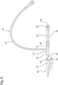
- Fig. 1 is a schematic diagram showing a state in which the urethral balloon catheter is inserted into a urinary bladder.
- a urethral balloon catheter 100 includes, as shown in Fig. 1 , a catheter main body 10, a probe (an instrument) 20, and a branched connector 40.
- the catheter main body 10 is formed in a tube shape such that fluid can flow through inside and the probe 20 can be inserted through inside.
- the catheter main body 10 according to this embodiment is formed of silicone rubber but may be formed of latex, natural rubber, isoprene rubber, thermoplastic resin, for example, PVC and urethan rubber, fluorocarbon rubber and fluorocarbon resin, or the like.
- a balloon 12 is provided near a distal end 11 of the catheter main body 10.
- the catheter main body is to be fixed in a urinary bladder 30 by expanding the balloon 12 in a state in which the balloon 12 is inserted into the urinary bladder 30.
- the branched connector 40 is formed of an elastic material, for example, silicone rubber but may be formed of latex, natural rubber, isoprene rubber, thermoplastic resin, for example, PVC and urethan rubber, fluorocarbon rubber and fluorocarbon resin, or the like.
- a fluorescent optode that measures the intensity of light emitted from a fluorescent dye reacting with urine 31 in the urinary bladder 30, a double fiber laser doppler probe, and a temperature sensor are incorporated in the probe 20. Consequently, the probe 20 can measure an oxygen partial pressure in urine. Coating may be applied to the probe 20 in order to reduce friction with a lumen of the catheter main body 10.
- a coating agent only has to be a material that can reduce the friction with the lumen of the catheter main body 10 such as Teflon (registered trademark) coat, Parylene, or hydrophilic polymer. Note that the coating agent explained above may be applied to the lumen side of the catheter main body 10.
- the urethral balloon catheter 100 is explained more in detail below.
- Fig. 2 is a sectional view showing the distal end of the urethral balloon catheter.
- Fig. 2(a) shows a state in which the probe 20 is housed in the catheter main body 10
- Fig. 2(b) shows a state in which the probe 20 projects from the catheter main body.
- the catheter main body 10 is configured by combining a tube portion 10a and an insertion end 10b as shown in Fig. 2 .
- a pair of lateral holes (side holes) 13 for the urine 31 stored in the urinary bladder 30 to flow through is formed near the distal end 11, that is, between the distal end 11 and the balloon 12 (see Fig. 1 ).
- the pair of lateral holes (side holes) 13 is located to be opposed and is respectively formed to pass through a wall portion 15 of the catheter main body 10 in a direction perpendicular to an axial direction Z.
- the pair of lateral holes (side holes) 13 is formed to have a long hole shape expanding in the axial direction Z.
- Two lateral holes (side holes) 13 are desirably formed. However, the number of the lateral holes (side holes) 13 is not limited to two.
- a longitudinal hole (distal hole) 14 is formed at the distal end 11 of the catheter main body 10.
- the longitudinal hole (distal hole) 14 has a substantially perfect circular shape and is formed to pass through the distal end 11 in the axial direction Z. That is, the longitudinal hole (distal hole) 14 passes through the distal end 11 of the catheter main body 10 in a direction perpendicular to a direction in which the pair of lateral holes (side holes) 13 passes through the catheter main body 10.
- the longitudinal hole (distal hole) may be a distal end portion formed at an obtuse angle by polishing the distal end portion of the catheter main body, or only the distal end portion may be manufactured by molding and bonded to the catheter main body.
- the inner circumference of the longitudinal hole (distal hole) 14 is formed to be the same as or shorter than the inner circumference of a channel 16 passing the inside of the catheter main body 10. That is, a flow passage area of the longitudinal hole (distal hole) 14 is the same as or smaller than a flow passage area of the channel 16.
- the inner circumference of the longitudinal hole (distal hole) 14 is formed longer than the outer circumference of the probe 20. Consequently, the probe 20 is capable of sliding to pass through the longitudinal hole (distal hole) 14.
- the longitudinal hole (distal hole) 14 may have a substantially perfect circular shape and the inner circumference of the longitudinal hole (distal hole) 14 may have substantially the same length as the outer circumference of the probe.
- the catheter main body 10 can prevent the probe 20 from moving in a direction perpendicular to the axial direction Z.
- the insertion end 10b of the catheter main body 10 includes an inclined portion 18, the inner circumferential surface of which is formed in a conical shape.
- the inclined portion 18 is formed such that an angle between the inclined portion 18 and the axial direction Z is an acute angle compared with the outer circumferential surface of the insertion end 10b. Consequently, when the probe 20 is pushed in toward the distal end 11, the probe 20 can easily pass through the longitudinal hole 14 while being guided by the inclined portion 18.
- the channel 16 and the probe 20 may be formed in separate conduits.
- Fig. 3 is an enlarged view showing the branched connector of the urethral balloon catheter.
- the branched connector 40 includes, as shown in Fig. 3 , a main body portion 41 and a sensor connection port portion 42 detachably coupled to the main body portion 41. Note that, in this embodiment, the main body portion 41 and the sensor connection port portion 42 are detachably provided. However, the main body portion 41 and the sensor connection port portion 42 may be integrally provided.
- the main body portion 41 is formed of silicone rubber and includes a first end portion 44 to which the catheter main body 10 is attached, a first hole portion 43 communicating with the catheter main body 10 being formed at the first end portion 44.
- An inclined surface 45 an opening portion of which is reduced in a funnel shape toward the first hole portion 43, is formed in the first end portion 44. Consequently, the distal end of the probe 20 inserted into the branched connector 40 is guided toward the first hole portion 43 by the inclined surface 45.
- a delivery conduit 46 for delivering gas or liquid such as air or sterilized water to expand the balloon 12 is provided in the main body portion 41.
- a one-way valve is equipped in the delivery conduit 46.
- a syringe can be connected to the one-way valve.
- a drainage pipe 47 communicating with the first hole portion 43 and branching in a direction crossing a direction in which the sensor connection port portion 42 is inserted into the main body portion 41, that is, a direction in which the probe 20 is inserted is provided.
- the drainage pipe 47 may be longer than the entire length of the branched connector 40 and a flow passage area of the conduit may be the same as a flow passage area of the branched connector 40. Consequently, when the urethral balloon catheter 100 is used, it is possible to prevent the catheter main body 10 from being pulled by an instrument or the like connected to the branched connector 40 and discharge urine without being retained in the branched connector 40.
- the drainage pipe 47 is provided in the branched connector 40, the probe 20 can be inserted into the catheter main body 10 through a route not having a bend.
- a funnel portion (not shown) is provided at the distal end of the drainage pipe 47.
- a urine storage bag or the like is provided to be connectable to the funnel portion. Consequently, drainage such as urine flowing into the branched connector 40 from the first hole portion 43 through the catheter main body 10 flows out to the urine storage bag or the like from the drainage pipe 47.
- the drainage pipe 47 according to this embodiment is provided in the main body portion 41 to extend in a direction perpendicular to a direction in which the sensor connection port portion 42 is inserted into the main body portion 41, that is, a direction in which the catheter main body 10 and the probe 20 are inserted.
- the drainage pipe 47 may be provided to extend in an oblique direction and a direction away from the first end portion 44 with respect to the direction in which the catheter main body 10 and the probe 20 are inserted of the main body portion 41 .
- the sensor connection port portion 42 is mainly formed of silicone rubber and includes a second end portion 49 in which a second hole portion 48 for inserting the wire-like probe 20 is formed.
- the sensor connection port portion 42 may be formed of ABS resin, polycarbonate, or the like.
- the second hole portion 48 is formed in the elastic member.
- the second hole portion 48 is formed as a circular-shape hole in the center of a sheet made of silicone rubber formed in a circular shape.
- the second hole portion 48 communicates with the first hole portion 43 and has a flow passage area smaller than a flow passage area of the first hole portion 43.
- the length of the inner circumference of the second hole portion 48 is larger than the length of the outer circumference of the probe 20 in a state in which the probe 20 is not inserted.
- the inner diameter of the second hole portion 48 is smaller than the outer diameter of the probe 20. Since the second hole portion 48 is formed in the sheet made of silicon rubber, the second hole portion 48 is provided to be expandable in diameter with the inner circumference extending when the probe 20 is inserted. At this time, since the second hole portion 48 is formed in the circular shape in the center of the sheet made of silicone rubber formed in the circular shape, tensile stress substantially uniformly acts when the second hole portion 48 is expanded in diameter. Therefore, a contact surface with the probe 20 adheres to the probe 20 to substantially uniformly tighten the probe 20 and high sealing properties can be realized. Note that, in this embodiment, the second hole portion 48 is formed in one sheet made of silicone rubber.
- the second hole portion 48 may be formed to pass through each of overlapped two or more sheets made of silicone rubber.
- the second end portion 49 may be formed in a cylindrical shape and may have a shape expanded in a circular shape like a flange at the end portion of a cylindrical shape portion.
- nothing is interposed in a channel connecting a joint portion 50 and the second hole portion 48.
- a valve for opening and closing the channel connecting the joint portion 50 and the second hole portion 48 may be provided.
- the sensor connection port portion 42 is provided with a joint portion 50 for detachably coupling with the main body portion 41.
- the joint portion 50 is formed of resin material in a cylindrical shape and integrally includes, near the center in in the axial direction of the cylindrical shape, that is, a direction in which the probe 20 is inserted, a flange portion 51 expanding in a direction perpendicular to the axis.
- the flange portion 51 is inserted into the funnel portion having the funnel shape formed in the main body portion 41, the flange portion 51 is inserted while pushing and expanding the funnel portion. Consequently, the sensor connection port portion 42 can be easily inserted into and pulled out from the main body portion 41.
- the joint portion 50 is fixed, at a certain degree of strength, to a part of the sensor connection port portion 42 formed of silicone rubber and is manufactured using a method such as rim molding.
- a flow passage area of the joint portion 50 is smaller than a flow passage area of a body portion 52 of the sensor connection port portion 42 but is larger than a flow passage area of the second hole portion 48.
- the sensor connection port portion 42 can be detached.
- the probe 20 can also be integrally detached simply by detaching the sensor connection port portion 42. Therefore, it is possible to facilitate replacement of the probe 20.
- the main body portion 41 and the sensor connection port portion 42 are coupled.
- the first hole portion 43 and the second hole portion 48 of the joint portion 50 are provided to be located on a straight line. Consequently, in the straight state in which the main body portion 41 and the sensor connection port portion 42 are not bent, if the wire-like probe 20 inserted from the second hole portion 48 passes through the joint portion 50, the probe 20 is directly guided by a channel formed in the joint portion 50 toward the first hole portion 43 or the inclined surface 45 formed around the first hole portion 43.
- the branched connector 40 of the urethral balloon catheter 100 comprises the first end portion 44 to which the catheter main body 10 is attached and having the first hole portion 43 communicating with the catheter main body 10 is formed; and the second end portion 49 including the elastic member and having the second hole portion 48 for inserting the wire-like probe 20 being formed in the elastic member.
- the second hole portion 48 communicates with the first hole portion 43 and has the flow passage area smaller than the flow passage area of the first hole portion 43. Consequently, the second hole portion 48 can adhere to an instrument such as the probe 20 inserted into the branched connector 40 to tighten the instrument, and any other instrument can be inserted into the second hole portion 48 if the other instrument is a wire-like instrument having the same degree of thickness. Therefore, it is possible to improve sealing properties on the contact surface with the probe 20 and improve versatility.
- the embodiment of the present invention is explained above. However, the embodiment of the invention explained facilitates understanding of the present invention and does not limit the present invention. The present invention can be changed and improved without departing from the gist of the present invention. Equivalents of the present invention are included in the present invention.
- the urethral balloon catheter 100 inserted into the urinary bladder 30 is explained.
- the present invention is not limited to this. The present invention may be applied to a catheter used for another site, for example, a catheter inserted into the upper urinary tract.
- the urethral balloon catheter 100 in which the catheter main body 10 is bonded to the branched connector 40 in advance is explained.
- the first end portion 44 may include a cylindrical shape portion 53 to be inserted into and attached to a funnel portion 61 of commercially available another catheter 60. Consequently, the present invention can be applied to various uses such as a catheter different in a distal end portion structure and thickness.
- the branched connector 40 is provided as a single member.
- the branched connector 40 may include the main body portion 41 and the sensor connection port portion 42 and may be detachably provided.
- the probe 20 is connected to measurement equipment by wired connection.
- a transmitting portion 54 for transmitting a detection result by the probe 20 to the measurement equipment may be provided at the second end portion 49 via a cable 55. Consequently, since a cable for wired connection is unnecessary, it is possible to enlarge a sphere of activity of a user in a clinical site.
- the present invention is applied to a urethral balloon catheter, in view of a situation in a medical site, the urethral balloon catheter is set in a body lower part.
- biological monitor equipment that needs to perform measurement in emergency, an ICU, and the like is often measurement equipment used in the upper half of the body or above.
Landscapes
- Health & Medical Sciences (AREA)
- Life Sciences & Earth Sciences (AREA)
- Heart & Thoracic Surgery (AREA)
- General Health & Medical Sciences (AREA)
- Animal Behavior & Ethology (AREA)
- Engineering & Computer Science (AREA)
- Biomedical Technology (AREA)
- Veterinary Medicine (AREA)
- Public Health (AREA)
- Biophysics (AREA)
- Hematology (AREA)
- Pulmonology (AREA)
- Anesthesiology (AREA)
- Medical Informatics (AREA)
- Surgery (AREA)
- Molecular Biology (AREA)
- Physics & Mathematics (AREA)
- Pathology (AREA)
- Urology & Nephrology (AREA)
- Physiology (AREA)
- Media Introduction/Drainage Providing Device (AREA)
- Materials For Medical Uses (AREA)
- External Artificial Organs (AREA)
- Epidemiology (AREA)
- Child & Adolescent Psychology (AREA)
Abstract
Description
- The present invention relates to a catheter capable of mainly measuring an oxygen partial pressure and a branched connector used in the catheter.
- Acute kidney injury (AKI) that occurs in 30 to 50% of inpatients in an intensive care unit adversely affects prognoses of the patients even if the acute kidney injury is mild. A death rate reaches as high as 60% when blood purification is necessary. Transition to chronic renal failure is also a problem. Low oxygen of the renal medulla is one of critical causes of the AKI. It is considered possible to estimate a renal medulla oxygen partial pressure by measuring an oxygen partial pressure in urine in the urinary bladder. In order to measure the oxygen partial pressure in the urine in the urinary bladder, there has been proposed a urethral catheter having an oxygen partial pressure measurement sensor projecting from a side hole portion of the urethral catheter for measuring an oxygen partial pressure in the urinary bladder or the wall of urinary bladder.
- The urethral catheter includes a catheter main body, a balloon portion, a branched connector, a sensor portion, and a urination route. The sensor portion for measuring an oxygen partial pressure is inserted into a hole portion formed in the branched connector and pass through the branched connector, and inserted into the catheter main body. In order to prevent a liquid leak in a connecting part of two instruments, there have been proposed a medical instrument for channel switching including a partition wall member having a slit in a syringe connecting part (see, for example, Patent Literature 1) and a medical instrument for guide wire fixing that can surely fix a guide wire even in a high moisture state (see, for example, Patent Literature 2).
-
- PTL 1:
Japanese Patent No. 4556701 - PTL 2:
Japanese Patent No. 5151322 - However, in the urethral catheter and the medical instrument according to the related art, when a sensor portion having very small thickness compared with the thickness of the catheter main body such as a wire-like sensor portion for measuring an oxygen partial pressure is used, the sensor portion is not sufficiently sealed and a liquid leak from a position where the sensor portion is inserted into the branched connector is likely to occur.
- In the medical instrument for channel switching according to the related art, since the distal end of a syringe is only inserted, an insertion amount is small. When an instrument having a large insertion amount such as the wire-like sensor portion is inserted through the partition wall member, a liquid leak is likely to occur.
- An object of the present invention is to provide a catheter and a branched connector that can solve the problems by the related art and improve sealing properties and have high versatility.
- The present invention is a branched connector used in a catheter, the branched connector comprising: a first end portion to which a catheter main body is attached and having a first hole portion communicating with the catheter main body being formed; and a second end portion including an elastic member and having a second hole portion for inserting a wire-like instrument being formed in the elastic member, wherein the second hole portion communicates with the first hole portion and has a flow passage area smaller than a flow passage area of the first hole portion.
- In this case, the elastic member may be formed of silicone rubber. The branched connector may include: a main body portion including the first end portion; and a sensor connection port portion including the second end portion, wherein a joint portion for detachably coupling to the main body portion. The main body portion and the sensor connection port portion may be formed of an elastic member, and the joint portion may be formed of a resin material. The joint portion may be formed in a cylindrical shape including a flange portion. The main body portion may be provided with a drainage pipe communicating with the first hole portion and branching in a direction crossing a direction in which the sensor connection port portion is inserted into the main body portion. The sensor connection port portion may be provided with a valve for opening and closing a channel connecting the joint portion and the second end portion. The first end portion may include a cylindrical shape portion for attaching another catheter.
- The present invention is a catheter including the above branched connector.
- In this case, an outer side of the second end portion may be provided with a transmitting portion for transmitting a detection result by the sensor.
- The present invention can provide a catheter and a branched connector that can improve sealing properties and have high versatility.
-
- [
Fig. 1] Fig. 1 is a schematic diagram showing a state in which a urethral balloon catheter is inserted into a urinary bladder. - [
Fig. 2] Fig. 2 is a sectional view schematically showing the distal end of the urethral balloon catheter. - [
Fig. 3] Fig. 3 is an enlarged view showing a branched connector of the urethral balloon catheter. - [
Fig. 4] Fig. 4 is an enlarged view showing a branched connector according to a modification. - [
Fig. 5] Fig. 5 is an enlarged view showing a branched connector according to a modification. - [
Fig. 6] Fig. 6 is an enlarged view showing a urethral balloon catheter according to a modification. - A urethral balloon catheter according to an embodiment of the present invention is explained with reference to the drawings.
-
Fig. 1 is a schematic diagram showing a state in which the urethral balloon catheter is inserted into a urinary bladder. - A
urethral balloon catheter 100 includes, as shown inFig. 1 , a cathetermain body 10, a probe (an instrument) 20, and abranched connector 40. - The catheter
main body 10 is formed in a tube shape such that fluid can flow through inside and theprobe 20 can be inserted through inside. The cathetermain body 10 according to this embodiment is formed of silicone rubber but may be formed of latex, natural rubber, isoprene rubber, thermoplastic resin, for example, PVC and urethan rubber, fluorocarbon rubber and fluorocarbon resin, or the like. Aballoon 12 is provided near adistal end 11 of the cathetermain body 10. The catheter main body is to be fixed in aurinary bladder 30 by expanding theballoon 12 in a state in which theballoon 12 is inserted into theurinary bladder 30. - The
branched connector 40 is formed of an elastic material, for example, silicone rubber but may be formed of latex, natural rubber, isoprene rubber, thermoplastic resin, for example, PVC and urethan rubber, fluorocarbon rubber and fluorocarbon resin, or the like. - A fluorescent optode (optical electrode) that measures the intensity of light emitted from a fluorescent dye reacting with
urine 31 in theurinary bladder 30, a double fiber laser doppler probe, and a temperature sensor are incorporated in theprobe 20. Consequently, theprobe 20 can measure an oxygen partial pressure in urine. Coating may be applied to theprobe 20 in order to reduce friction with a lumen of the cathetermain body 10. A coating agent only has to be a material that can reduce the friction with the lumen of the cathetermain body 10 such as Teflon (registered trademark) coat, Parylene, or hydrophilic polymer. Note that the coating agent explained above may be applied to the lumen side of the cathetermain body 10. - The
urethral balloon catheter 100 is explained more in detail below. -
Fig. 2 is a sectional view showing the distal end of the urethral balloon catheter. InFig. 2, Fig. 2(a) shows a state in which theprobe 20 is housed in the cathetermain body 10 andFig. 2(b) shows a state in which theprobe 20 projects from the catheter main body. - The catheter
main body 10 is configured by combining atube portion 10a and aninsertion end 10b as shown inFig. 2 . In the cathetermain body 10, a pair of lateral holes (side holes) 13 for theurine 31 stored in theurinary bladder 30 to flow through is formed near thedistal end 11, that is, between thedistal end 11 and the balloon 12 (seeFig. 1 ). The pair of lateral holes (side holes) 13 is located to be opposed and is respectively formed to pass through awall portion 15 of the cathetermain body 10 in a direction perpendicular to an axial direction Z. The pair of lateral holes (side holes) 13 is formed to have a long hole shape expanding in the axial direction Z. Two lateral holes (side holes) 13 are desirably formed. However, the number of the lateral holes (side holes) 13 is not limited to two. - A longitudinal hole (distal hole) 14 is formed at the
distal end 11 of the cathetermain body 10. The longitudinal hole (distal hole) 14 has a substantially perfect circular shape and is formed to pass through thedistal end 11 in the axial direction Z. That is, the longitudinal hole (distal hole) 14 passes through thedistal end 11 of the cathetermain body 10 in a direction perpendicular to a direction in which the pair of lateral holes (side holes) 13 passes through the cathetermain body 10. The longitudinal hole (distal hole) may be a distal end portion formed at an obtuse angle by polishing the distal end portion of the catheter main body, or only the distal end portion may be manufactured by molding and bonded to the catheter main body. - The inner circumference of the longitudinal hole (distal hole) 14 is formed to be the same as or shorter than the inner circumference of a
channel 16 passing the inside of the cathetermain body 10. That is, a flow passage area of the longitudinal hole (distal hole) 14 is the same as or smaller than a flow passage area of thechannel 16. The inner circumference of the longitudinal hole (distal hole) 14 is formed longer than the outer circumference of theprobe 20. Consequently, theprobe 20 is capable of sliding to pass through the longitudinal hole (distal hole) 14. At this time, in the cathetermain body 10, the longitudinal hole (distal hole) 14 may have a substantially perfect circular shape and the inner circumference of the longitudinal hole (distal hole) 14 may have substantially the same length as the outer circumference of the probe. The cathetermain body 10 can prevent theprobe 20 from moving in a direction perpendicular to the axial direction Z. - The
insertion end 10b of the cathetermain body 10 includes aninclined portion 18, the inner circumferential surface of which is formed in a conical shape. Theinclined portion 18 is formed such that an angle between theinclined portion 18 and the axial direction Z is an acute angle compared with the outer circumferential surface of theinsertion end 10b. Consequently, when theprobe 20 is pushed in toward thedistal end 11, theprobe 20 can easily pass through thelongitudinal hole 14 while being guided by theinclined portion 18. - In the catheter
main body 10, since a gap is formed between thechannel 16 and theprobe 20, theurine 31 can flow in the gap. Note that, in the cathetermain body 10, thechannel 16 and theprobe 20 may be formed in separate conduits. -
Fig. 3 is an enlarged view showing the branched connector of the urethral balloon catheter. - The branched
connector 40 includes, as shown inFig. 3 , amain body portion 41 and a sensorconnection port portion 42 detachably coupled to themain body portion 41. Note that, in this embodiment, themain body portion 41 and the sensorconnection port portion 42 are detachably provided. However, themain body portion 41 and the sensorconnection port portion 42 may be integrally provided. - The
main body portion 41 is formed of silicone rubber and includes afirst end portion 44 to which the cathetermain body 10 is attached, afirst hole portion 43 communicating with the cathetermain body 10 being formed at thefirst end portion 44. - An
inclined surface 45, an opening portion of which is reduced in a funnel shape toward thefirst hole portion 43, is formed in thefirst end portion 44. Consequently, the distal end of theprobe 20 inserted into the branchedconnector 40 is guided toward thefirst hole portion 43 by theinclined surface 45. - In the
main body portion 41, adelivery conduit 46 for delivering gas or liquid such as air or sterilized water to expand theballoon 12 is provided. A one-way valve is equipped in thedelivery conduit 46. A syringe can be connected to the one-way valve. - In the
main body portion 41, adrainage pipe 47 communicating with thefirst hole portion 43 and branching in a direction crossing a direction in which the sensorconnection port portion 42 is inserted into themain body portion 41, that is, a direction in which theprobe 20 is inserted is provided. Thedrainage pipe 47 may be longer than the entire length of the branchedconnector 40 and a flow passage area of the conduit may be the same as a flow passage area of the branchedconnector 40. Consequently, when theurethral balloon catheter 100 is used, it is possible to prevent the cathetermain body 10 from being pulled by an instrument or the like connected to the branchedconnector 40 and discharge urine without being retained in the branchedconnector 40. Since thedrainage pipe 47 is provided in the branchedconnector 40, theprobe 20 can be inserted into the cathetermain body 10 through a route not having a bend. A funnel portion (not shown) is provided at the distal end of thedrainage pipe 47. A urine storage bag or the like is provided to be connectable to the funnel portion. Consequently, drainage such as urine flowing into the branchedconnector 40 from thefirst hole portion 43 through the cathetermain body 10 flows out to the urine storage bag or the like from thedrainage pipe 47. Note that thedrainage pipe 47 according to this embodiment is provided in themain body portion 41 to extend in a direction perpendicular to a direction in which the sensorconnection port portion 42 is inserted into themain body portion 41, that is, a direction in which the cathetermain body 10 and theprobe 20 are inserted. However, not only this, but, like thedelivery conduit 46, thedrainage pipe 47 may be provided to extend in an oblique direction and a direction away from thefirst end portion 44 with respect to the direction in which the cathetermain body 10 and theprobe 20 are inserted of themain body portion 41 . - The sensor
connection port portion 42 is mainly formed of silicone rubber and includes asecond end portion 49 in which asecond hole portion 48 for inserting the wire-like probe 20 is formed. Note that the sensorconnection port portion 42 may be formed of ABS resin, polycarbonate, or the like. Thesecond hole portion 48 is formed in the elastic member. In this embodiment, thesecond hole portion 48 is formed as a circular-shape hole in the center of a sheet made of silicone rubber formed in a circular shape. Thesecond hole portion 48 communicates with thefirst hole portion 43 and has a flow passage area smaller than a flow passage area of thefirst hole portion 43. The length of the inner circumference of thesecond hole portion 48 is larger than the length of the outer circumference of theprobe 20 in a state in which theprobe 20 is not inserted. That is, when theprobe 20 has a circular cross section, the inner diameter of thesecond hole portion 48 is smaller than the outer diameter of theprobe 20. Since thesecond hole portion 48 is formed in the sheet made of silicon rubber, thesecond hole portion 48 is provided to be expandable in diameter with the inner circumference extending when theprobe 20 is inserted. At this time, since thesecond hole portion 48 is formed in the circular shape in the center of the sheet made of silicone rubber formed in the circular shape, tensile stress substantially uniformly acts when thesecond hole portion 48 is expanded in diameter. Therefore, a contact surface with theprobe 20 adheres to theprobe 20 to substantially uniformly tighten theprobe 20 and high sealing properties can be realized. Note that, in this embodiment, thesecond hole portion 48 is formed in one sheet made of silicone rubber. However, thesecond hole portion 48 may be formed to pass through each of overlapped two or more sheets made of silicone rubber. Thesecond end portion 49 may be formed in a cylindrical shape and may have a shape expanded in a circular shape like a flange at the end portion of a cylindrical shape portion. Further, in the sensorconnection port portion 42 according to this embodiment, nothing is interposed in a channel connecting ajoint portion 50 and thesecond hole portion 48. However, a valve for opening and closing the channel connecting thejoint portion 50 and thesecond hole portion 48 may be provided. - The sensor
connection port portion 42 is provided with ajoint portion 50 for detachably coupling with themain body portion 41. Thejoint portion 50 is formed of resin material in a cylindrical shape and integrally includes, near the center in in the axial direction of the cylindrical shape, that is, a direction in which theprobe 20 is inserted, aflange portion 51 expanding in a direction perpendicular to the axis. When theflange portion 51 is inserted into the funnel portion having the funnel shape formed in themain body portion 41, theflange portion 51 is inserted while pushing and expanding the funnel portion. Consequently, the sensorconnection port portion 42 can be easily inserted into and pulled out from themain body portion 41. Thejoint portion 50 is fixed, at a certain degree of strength, to a part of the sensorconnection port portion 42 formed of silicone rubber and is manufactured using a method such as rim molding. - A flow passage area of the
joint portion 50 is smaller than a flow passage area of abody portion 52 of the sensorconnection port portion 42 but is larger than a flow passage area of thesecond hole portion 48. In thebranched connector 40, the sensorconnection port portion 42 can be detached. Theprobe 20 can also be integrally detached simply by detaching the sensorconnection port portion 42. Therefore, it is possible to facilitate replacement of theprobe 20. - In the
branched connector 40, themain body portion 41 and the sensorconnection port portion 42 are coupled. In a straight state in which themain body portion 41 and the sensorconnection port portion 42 are not bent, thefirst hole portion 43 and thesecond hole portion 48 of thejoint portion 50 are provided to be located on a straight line. Consequently, in the straight state in which themain body portion 41 and the sensorconnection port portion 42 are not bent, if the wire-like probe 20 inserted from thesecond hole portion 48 passes through thejoint portion 50, theprobe 20 is directly guided by a channel formed in thejoint portion 50 toward thefirst hole portion 43 or theinclined surface 45 formed around thefirst hole portion 43. When theprobe 20 is inserted into the cathetermain body 10, it is difficult to insert theprobe 20 to the distal end of the cathetermain body 10 because of frictional resistance. Therefore, lubricant is used or a guide instrument (not shown) or the like for guiding theprobe 20 is used. - The branched
connector 40 of theurethral balloon catheter 100 according to this embodiment comprises thefirst end portion 44 to which the cathetermain body 10 is attached and having thefirst hole portion 43 communicating with the cathetermain body 10 is formed; and thesecond end portion 49 including the elastic member and having thesecond hole portion 48 for inserting the wire-like probe 20 being formed in the elastic member. Thesecond hole portion 48 communicates with thefirst hole portion 43 and has the flow passage area smaller than the flow passage area of thefirst hole portion 43. Consequently, thesecond hole portion 48 can adhere to an instrument such as theprobe 20 inserted into the branchedconnector 40 to tighten the instrument, and any other instrument can be inserted into thesecond hole portion 48 if the other instrument is a wire-like instrument having the same degree of thickness. Therefore, it is possible to improve sealing properties on the contact surface with theprobe 20 and improve versatility. - The embodiment of the present invention is explained above. However, the embodiment of the invention explained facilitates understanding of the present invention and does not limit the present invention. The present invention can be changed and improved without departing from the gist of the present invention. Equivalents of the present invention are included in the present invention. For example, in the embodiment, the
urethral balloon catheter 100 inserted into theurinary bladder 30 is explained. However, the present invention is not limited to this. The present invention may be applied to a catheter used for another site, for example, a catheter inserted into the upper urinary tract. - In the embodiment, the
urethral balloon catheter 100 in which the cathetermain body 10 is bonded to the branchedconnector 40 in advance is explained. However, not only this, but, for example, as shown inFig. 4 , thefirst end portion 44 may include acylindrical shape portion 53 to be inserted into and attached to afunnel portion 61 of commercially available anothercatheter 60. Consequently, the present invention can be applied to various uses such as a catheter different in a distal end portion structure and thickness. Note that, inFig. 4 , the branchedconnector 40 is provided as a single member. However, as shown inFig. 5 , the branchedconnector 40 may include themain body portion 41 and the sensorconnection port portion 42 and may be detachably provided. - Further, in the embodiment, the
probe 20 is connected to measurement equipment by wired connection. However, not only this, but, for example, as shown inFig. 6 , a transmittingportion 54 for transmitting a detection result by theprobe 20 to the measurement equipment may be provided at thesecond end portion 49 via acable 55. Consequently, since a cable for wired connection is unnecessary, it is possible to enlarge a sphere of activity of a user in a clinical site. When the present invention is applied to a urethral balloon catheter, in view of a situation in a medical site, the urethral balloon catheter is set in a body lower part. However, biological monitor equipment that needs to perform measurement in emergency, an ICU, and the like is often measurement equipment used in the upper half of the body or above. Therefore, in extending an extension cord from the body lower part to a body upper part, disadvantages such as that from a viewpoint of handling of equipment and an increase in an equipment unit price are easily imagined. Therefore, by providing the transmittingportion 54 for data at the end of the branchedconnector 40 via thecable 55 to make the extension cord unnecessary and providing a data receiving portion in the biological monitor equipment, it is possible to provide a more convenient product. - Furthermore, in the embodiment, a case in which the wire-
like probe 20 is inserted into thesecond hole portion 48 of theurethral balloon catheter 100 is explained. However, not only this, but, an instrument other than the sensor and the like may be inserted into thesecond hole portion 48 if the instrument is an instrument extending in a wire shape. -
- 10
- Catheter main body
- 10a
- Tube portion
- 10b
- Insertion end
- 11
- Distal end
- 12
- Balloon
- 14
- Longitudinal hole
- 15
- Wall portion
- 16
- Channel
- 18
- Inclined portion
- 20
- Probe (instrument)
- 30
- Urinary bladder
- 31
- Urine
- 40
- Branched connector
- 41
- Main body portion
- 42
- Sensor connection port portion
- 43
- First hole portion
- 44
- First end portion
- 45
- Inclined surface
- 46
- Delivery conduit
- 47
- Drainage pipe
- 48
- Second hole portion
- 49
- Second end portion
- 50
- Joint portion
- 51
- Flange portion
- 52
- Body portion
- 53
- Cylindrical shape portion
- 54
- Transmitting portion
- 55
- Cable
- 60
- Catheter
- 61
- Funnel portion
- 100
- Urethral balloon catheter
- Z
- Axial direction
Claims (10)
- A branched connector used in a catheter, the branched connector comprising:a first end portion to which a catheter main body is attached and having a first hole portion communicating with the catheter main body being formed; anda second end portion including an elastic member and having a second hole portion for inserting a wire-like instrument being formed in the elastic member,wherein, the second hole portion communicates with the first hole portion and has a flow passage area smaller than a flow passage area of the first hole portion.
- The branched connector according to claim 1, wherein the elastic member is formed of silicone rubber.
- The branched connector according to claim 1 or 2, further comprising:a main body portion including the first end portion; anda sensor connection port portion including the second end portion,wherein the sensor connection port portion is provided with a joint portion for detachably coupling to the main body portion.
- The branched connector according to claim 3, wherein the main body portion and the sensor connection port portion are formed of an elastic member, and the joint portion is formed of a resin material.
- The branched connector according to claim 3 or 4, wherein the joint portion is formed in a cylindrical shape including a flange portion.
- The branched connector according to any one of claims 3 to 5, wherein the main body portion is provided with a drainage pipe communicating with the first hole portion and branching in a direction crossing a direction in which the sensor connection port portion is inserted into the main body portion.
- The branched connector according to any one of claims 3 to 6, wherein the sensor connection port portion is provided with a valve for opening and closing a channel connecting the joint portion and the second end portion.
- The branched connector according to any one of claims 1 to 7, wherein the first end portion includes a cylindrical shape portion for attaching another catheter.
- A catheter comprising the branched connector according to any one of claims 1 to 8.
- The catheter according to claim 9, wherein an outer side of the second end portion is provided with a transmitting portion for transmitting a detection result by the sensor.
Applications Claiming Priority (2)
| Application Number | Priority Date | Filing Date | Title |
|---|---|---|---|
| JP2020088871 | 2020-05-21 | ||
| PCT/JP2021/019127 WO2021235513A1 (en) | 2020-05-21 | 2021-05-20 | Branched connector and catheter |
Publications (2)
| Publication Number | Publication Date |
|---|---|
| EP4154938A1 true EP4154938A1 (en) | 2023-03-29 |
| EP4154938A4 EP4154938A4 (en) | 2024-06-26 |
Family
ID=78707941
Family Applications (1)
| Application Number | Title | Priority Date | Filing Date |
|---|---|---|---|
| EP21807918.4A Pending EP4154938A4 (en) | 2020-05-21 | 2021-05-20 | Branched connector and catheter |
Country Status (6)
| Country | Link |
|---|---|
| US (1) | US20230211124A1 (en) |
| EP (1) | EP4154938A4 (en) |
| JP (1) | JP7610211B2 (en) |
| KR (1) | KR20230012630A (en) |
| AU (1) | AU2021275293B2 (en) |
| WO (1) | WO2021235513A1 (en) |
Families Citing this family (1)
| Publication number | Priority date | Publication date | Assignee | Title |
|---|---|---|---|---|
| AU2024396820A1 (en) * | 2023-12-07 | 2026-05-14 | The University Of Osaka | Catheter |
Family Cites Families (13)
| Publication number | Priority date | Publication date | Assignee | Title |
|---|---|---|---|---|
| DE8607358U1 (en) * | 1986-03-18 | 1986-05-28 | Ruß, Jürgen, 5300 Bonn | Tubular, flexible probe for insertion into the trachea and bronchi |
| AU704588B2 (en) | 1995-10-24 | 1999-04-29 | Cook Incorporated | Hemostasis cannula |
| US6179806B1 (en) | 1999-08-05 | 2001-01-30 | Scimed Life Systems, Inc. | Self-occluding catheter |
| EP1848913B1 (en) * | 2005-02-14 | 2013-07-10 | Industrie Borla S.p.A. | Valved fluid connector |
| JP4556701B2 (en) | 2005-02-17 | 2010-10-06 | 株式会社ジェイ・エム・エス | Channel switching device |
| US20080027416A1 (en) * | 2006-07-25 | 2008-01-31 | Hamel Kory P | Catheter with Light Source |
| JP5151322B2 (en) | 2007-08-31 | 2013-02-27 | 住友ベークライト株式会社 | Medical device for fixing guide wire |
| WO2014162347A1 (en) * | 2013-04-01 | 2014-10-09 | テルモ株式会社 | Connector and transfusion set |
| AU2014302183A1 (en) * | 2013-06-27 | 2016-02-11 | Theranova, Llc | Sensing foley catheter |
| US20190282157A1 (en) | 2016-11-04 | 2019-09-19 | Oxford Optronix Limited | Sensing a property of a bladder wall |
| US11052234B2 (en) * | 2017-02-15 | 2021-07-06 | Celeste V. Bonham | Connector with integrated non-return check valve for extension tubing and urology collection systems |
| CN115251911B (en) | 2017-03-30 | 2024-10-11 | 泰尔茂株式会社 | Oxygen measurement equipment |
| JP7301291B2 (en) * | 2019-10-15 | 2023-07-03 | 株式会社塚田メディカル・リサーチ | Catheter and oxygen partial pressure measurement method |
-
2021
- 2021-05-20 KR KR1020227044767A patent/KR20230012630A/en active Pending
- 2021-05-20 WO PCT/JP2021/019127 patent/WO2021235513A1/en not_active Ceased
- 2021-05-20 AU AU2021275293A patent/AU2021275293B2/en active Active
- 2021-05-20 JP JP2022524531A patent/JP7610211B2/en active Active
- 2021-05-20 US US17/926,348 patent/US20230211124A1/en active Pending
- 2021-05-20 EP EP21807918.4A patent/EP4154938A4/en active Pending
Also Published As
| Publication number | Publication date |
|---|---|
| KR20230012630A (en) | 2023-01-26 |
| JPWO2021235513A1 (en) | 2021-11-25 |
| AU2021275293A1 (en) | 2023-01-05 |
| AU2021275293B2 (en) | 2026-04-09 |
| US20230211124A1 (en) | 2023-07-06 |
| JP7610211B2 (en) | 2025-01-08 |
| WO2021235513A1 (en) | 2021-11-25 |
| CN115666706A (en) | 2023-01-31 |
| EP4154938A4 (en) | 2024-06-26 |
Similar Documents
| Publication | Publication Date | Title |
|---|---|---|
| US4874378A (en) | Catheter sheath introducer | |
| US8715228B2 (en) | Balloon catheter with metal shaft | |
| US20090318757A1 (en) | Flexible visually directed medical intubation instrument and method | |
| US20090318798A1 (en) | Flexible visually directed medical intubation instrument and method | |
| US20190282157A1 (en) | Sensing a property of a bladder wall | |
| EP0208787A1 (en) | Medical guiding micro-tube | |
| AU2021275293B2 (en) | Branched connector and catheter | |
| US11357899B2 (en) | Measuring device and method for measuring a property of a fluid in a line | |
| US20120136339A1 (en) | Protective sleeve for a catheter | |
| JPH0928665A (en) | Catheter | |
| US20100106051A1 (en) | Single lumen catheter with separate tubes therein | |
| JP7301291B2 (en) | Catheter and oxygen partial pressure measurement method | |
| JP2019170691A (en) | Intra-aortic balloon catheter | |
| CN115666706B (en) | Branch connector and catheter | |
| CN221771208U (en) | Medical Devices and Systems | |
| US5823967A (en) | Flush valve with cable attachment | |
| CN210698464U (en) | catheter with sheath | |
| US5820565A (en) | Flush valve with interlocking seal | |
| CN219397176U (en) | Endoscope guide | |
| CN217338531U (en) | Flexible bladder soft endoscope sheath | |
| JP2025091565A (en) | catheter | |
| CN218046176U (en) | Multi-channel joint | |
| CN215875924U (en) | Coaxial double-cavity micro-catheter for delivering bi-component hydrogel | |
| CN218484996U (en) | A disposable urethral dilator that can be torn off and viewed inside | |
| JP2025091553A (en) | Balloon catheter |
Legal Events
| Date | Code | Title | Description |
|---|---|---|---|
| STAA | Information on the status of an ep patent application or granted ep patent |
Free format text: STATUS: THE INTERNATIONAL PUBLICATION HAS BEEN MADE |
|
| PUAI | Public reference made under article 153(3) epc to a published international application that has entered the european phase |
Free format text: ORIGINAL CODE: 0009012 |
|
| STAA | Information on the status of an ep patent application or granted ep patent |
Free format text: STATUS: REQUEST FOR EXAMINATION WAS MADE |
|
| 17P | Request for examination filed |
Effective date: 20221214 |
|
| AK | Designated contracting states |
Kind code of ref document: A1 Designated state(s): AL AT BE BG CH CY CZ DE DK EE ES FI FR GB GR HR HU IE IS IT LI LT LU LV MC MK MT NL NO PL PT RO RS SE SI SK SM TR |
|
| DAV | Request for validation of the european patent (deleted) | ||
| DAX | Request for extension of the european patent (deleted) | ||
| A4 | Supplementary search report drawn up and despatched |
Effective date: 20240527 |
|
| RIC1 | Information provided on ipc code assigned before grant |
Ipc: A61B 5/20 20060101ALI20240522BHEP Ipc: A61B 5/01 20060101ALI20240522BHEP Ipc: A61M 25/00 20060101ALI20240522BHEP Ipc: A61M 1/00 20060101ALI20240522BHEP Ipc: A61B 5/00 20060101ALI20240522BHEP Ipc: A61M 39/10 20060101AFI20240522BHEP |