EP4154934A1 - An introducer sheath having an intentional friction zone to hold in position a delivery system suitable for implantable intravascular devices - Google Patents
An introducer sheath having an intentional friction zone to hold in position a delivery system suitable for implantable intravascular devices Download PDFInfo
- Publication number
- EP4154934A1 EP4154934A1 EP22196746.6A EP22196746A EP4154934A1 EP 4154934 A1 EP4154934 A1 EP 4154934A1 EP 22196746 A EP22196746 A EP 22196746A EP 4154934 A1 EP4154934 A1 EP 4154934A1
- Authority
- EP
- European Patent Office
- Prior art keywords
- introducer sheath
- intentional
- friction zone
- straight
- section
- Prior art date
- Legal status (The legal status is an assumption and is not a legal conclusion. Google has not performed a legal analysis and makes no representation as to the accuracy of the status listed.)
- Pending
Links
Images




Classifications
-
- A—HUMAN NECESSITIES
- A61—MEDICAL OR VETERINARY SCIENCE; HYGIENE
- A61B—DIAGNOSIS; SURGERY; IDENTIFICATION
- A61B17/00—Surgical instruments, devices or methods
- A61B17/12—Surgical instruments, devices or methods for ligaturing or otherwise compressing tubular parts of the body, e.g. blood vessels or umbilical cord
- A61B17/12022—Occluding by internal devices, e.g. balloons or releasable wires
- A61B17/12131—Occluding by internal devices, e.g. balloons or releasable wires characterised by the type of occluding device
- A61B17/1214—Coils or wires
-
- A—HUMAN NECESSITIES
- A61—MEDICAL OR VETERINARY SCIENCE; HYGIENE
- A61M—DEVICES FOR INTRODUCING MEDIA INTO, OR ONTO, THE BODY; DEVICES FOR TRANSDUCING BODY MEDIA OR FOR TAKING MEDIA FROM THE BODY; DEVICES FOR PRODUCING OR ENDING SLEEP OR STUPOR
- A61M25/00—Catheters; Hollow probes
- A61M25/0043—Catheters; Hollow probes characterised by structural features
-
- A—HUMAN NECESSITIES
- A61—MEDICAL OR VETERINARY SCIENCE; HYGIENE
- A61B—DIAGNOSIS; SURGERY; IDENTIFICATION
- A61B17/00—Surgical instruments, devices or methods
- A61B17/12—Surgical instruments, devices or methods for ligaturing or otherwise compressing tubular parts of the body, e.g. blood vessels or umbilical cord
- A61B17/12022—Occluding by internal devices, e.g. balloons or releasable wires
- A61B17/12099—Occluding by internal devices, e.g. balloons or releasable wires characterised by the location of the occluder
- A61B17/12109—Occluding by internal devices, e.g. balloons or releasable wires characterised by the location of the occluder in a blood vessel
- A61B17/12113—Occluding by internal devices, e.g. balloons or releasable wires characterised by the location of the occluder in a blood vessel within an aneurysm
-
- A—HUMAN NECESSITIES
- A61—MEDICAL OR VETERINARY SCIENCE; HYGIENE
- A61M—DEVICES FOR INTRODUCING MEDIA INTO, OR ONTO, THE BODY; DEVICES FOR TRANSDUCING BODY MEDIA OR FOR TAKING MEDIA FROM THE BODY; DEVICES FOR PRODUCING OR ENDING SLEEP OR STUPOR
- A61M25/00—Catheters; Hollow probes
- A61M25/0009—Making of catheters or other medical or surgical tubes
-
- A—HUMAN NECESSITIES
- A61—MEDICAL OR VETERINARY SCIENCE; HYGIENE
- A61M—DEVICES FOR INTRODUCING MEDIA INTO, OR ONTO, THE BODY; DEVICES FOR TRANSDUCING BODY MEDIA OR FOR TAKING MEDIA FROM THE BODY; DEVICES FOR PRODUCING OR ENDING SLEEP OR STUPOR
- A61M25/00—Catheters; Hollow probes
- A61M25/01—Introducing, guiding, advancing, emplacing or holding catheters
- A61M25/06—Body-piercing guide needles or the like
- A61M25/0662—Guide tubes
-
- A—HUMAN NECESSITIES
- A61—MEDICAL OR VETERINARY SCIENCE; HYGIENE
- A61B—DIAGNOSIS; SURGERY; IDENTIFICATION
- A61B17/00—Surgical instruments, devices or methods
- A61B2017/00526—Methods of manufacturing
-
- A—HUMAN NECESSITIES
- A61—MEDICAL OR VETERINARY SCIENCE; HYGIENE
- A61B—DIAGNOSIS; SURGERY; IDENTIFICATION
- A61B17/00—Surgical instruments, devices or methods
- A61B17/12—Surgical instruments, devices or methods for ligaturing or otherwise compressing tubular parts of the body, e.g. blood vessels or umbilical cord
- A61B17/12022—Occluding by internal devices, e.g. balloons or releasable wires
- A61B2017/1205—Introduction devices
-
- A—HUMAN NECESSITIES
- A61—MEDICAL OR VETERINARY SCIENCE; HYGIENE
- A61M—DEVICES FOR INTRODUCING MEDIA INTO, OR ONTO, THE BODY; DEVICES FOR TRANSDUCING BODY MEDIA OR FOR TAKING MEDIA FROM THE BODY; DEVICES FOR PRODUCING OR ENDING SLEEP OR STUPOR
- A61M25/00—Catheters; Hollow probes
- A61M25/01—Introducing, guiding, advancing, emplacing or holding catheters
- A61M25/06—Body-piercing guide needles or the like
- A61M25/0662—Guide tubes
- A61M2025/0681—Systems with catheter and outer tubing, e.g. sheath, sleeve or guide tube
-
- A—HUMAN NECESSITIES
- A61—MEDICAL OR VETERINARY SCIENCE; HYGIENE
- A61M—DEVICES FOR INTRODUCING MEDIA INTO, OR ONTO, THE BODY; DEVICES FOR TRANSDUCING BODY MEDIA OR FOR TAKING MEDIA FROM THE BODY; DEVICES FOR PRODUCING OR ENDING SLEEP OR STUPOR
- A61M25/00—Catheters; Hollow probes
- A61M25/0043—Catheters; Hollow probes characterised by structural features
- A61M25/0045—Catheters; Hollow probes characterised by structural features multi-layered, e.g. coated
Definitions
- the present invention relates to an intervascular intervention system for delivery of an implantable intravascular device used during an endovascular treatment or procedure.
- the present invention is directed to an introducer sheath having an intentional friction zone to maintain in position a delivery system suitable for use with implantable intravascular devices (e.g., embolic coils) of varying outer diameter during endovascular treatment (e.g., brain aneurysm).
- implantable intravascular devices e.g., embolic coils
- endovascular treatment e.g., brain aneurysm
- Implantable intravascular devices are commonly used in the endovascular procedures or treatments of various vascular ailments, for example, brain aneurysms.
- a catheter is inserted into the femoral artery in patient's leg and guided by imaging navigated through the vessel to the target site in the brain where the aneurysm is located. With the distal end of the catheter properly positioned on a proximal side of the aneurysm, a microcatheter is tracked through the catheter to the proximal side of the aneurysm.
- a delivery and deployment system loaded with an implantable intravascular device e.g., embolic coil
- an implantable intravascular device e.g., embolic coil
- the implantable intravascular device is secured to the delivery system, typically via a wire.
- the wire When properly positioned at the target site (e.g., at the location of the aneurysm) the wire is severed or detached releasing the implantable intravascular device (e.g., embolic coil) to be deposited within the aneurysm. This process is repeated until the area of the vessel with the weakened wall is tightly packed with numerous embolic coils occluding blood flow thereto thereby preventing rupture. Severing of the embolic coil from the securement wire is typically achieved by passing of a small electrical current through the wire.
- the present invention is directed to an intravascular intervention system including an introducer sheath having at least one intentional friction zone along a section thereof imposing an intentional friction force on the outer surface of a catheter shaft slidable therein.
- the friction zone representing a non-straight (e.g., curved or bent) section of the introducer sheath and/or a section of the introducer sheath whose inner wall has a reduced inner diameter (e.g., fused heat shrink material).
- sufficient axial force may be applied to overcome the imposed intentional friction force and advance the intravascular treatment device in a distal direction to a desired target site in the artery. Once properly positioned, the imposed intentional friction force ensures that the intravascular treatment device is maintained at the desired target site when being deployed.
- Another aspect of the present invention relates to a method of manufacturing an introducer sheath of an intravascular intervention system.
- a straight introducer sheath having a proximal end, an opposite distal end, and a longitudinal lumen of uniform inner diameter defined therebetween is provided.
- Radially about an outer surface of the introducer sheath a heat shrink material is positioned.
- Into the longitudinal lumen of the straight introducer sheath a non-straight mandrel is inserted.
- Another aspect of the present invention is directed to a method of manufacturing an introducer sheath of an intravascular intervention system by providing a straight introducer sheath having a proximal end, an opposite distal end, and a longitudinal lumen having a uniform inner diameter therebetween
- a heat shrink material is applied to a section of an inner wall of the straight introducer sheath and thereafter a straight mandrel is inserted into the lumen of the straight introducer sheath.
- Heat is applied at a predetermined temperature for a predetermined period of time sufficient to reflow the applied heat shrink material reducing the inner diameter of the longitudinal lumen along the section of the inner wall of the straight introducer sheath forming an intentional friction zone of an assembled structure.
- the staight mandrel is removed from the assembled structure.
- Still yet another aspect of the present invention relates to a method for using an intravascular intervention system by providing an introducer sheath having a proximal end, an opposite distal end, a longitudinal lumen with an inner diameter extending therebetween the proximal and distal ends, and an intentional friction zone along a section of the introducer sheath.
- a catheter shaft is introduced into the longitudinal lumen of the introducer sheath.
- sufficient force is applied in a distal direction on a proximal end of the catheter shaft to overcome an intentional frictional force imposed by the intentional friction zone of the introducer sheath on an outer surface of the catheter shaft.
- the catheter shaft Upon reaching the target position, the catheter shaft is retained at the target position by the imposed intentional frictional force.
- distal or proximal are used in the following description with respect to a position or direction relative to the treating physician or medical interventionalist.
- distal or disally are a position distant from or in a direction away from the physician or interventionalist.
- Proximal or “proximally” or “proximate” are a position near or in a direction toward the physician or medical interventionist.
- occlusion or “clot” or “blockage” are used interchangeably.
- an endovascular treatment procedure e.g., coil embolization
- the delivery and detachment/deployment system to reliably deliver and deposit the implantable intravascular device (e.g., embolic coil) at a precise location or target site (e.g., aneurysm) within a vessel or artery.
- the implantable intravascular device e.g., embolic coil
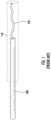
- the implantable intravascular device is secured to the distal end of a delivery system that together as a unit are advanced to a target site in the vessel or artery via a conventional introducer sheath representing a straight (parallel to the longitudinal axis running therethrough) tubing, as illustrated in the exemplary prior art assembly of Figure 1 .
- Delivery system 100 has an outer diameter of approximately 0.014". Secured to the distal end of the delivery system 100 is a coil 105 (implantable intravascular device) with an outer diameter of approximately 0.009". Together the delivery system loaded with the coil as a unit are receivable so as to freely slide in an axial direction within the lumen of the conventional straight introducer sheath 110 having an inner diameter of approximately 0.017".
- the conventional introducer sheath representing a straight (parallel to the longitudinal axis configuration) cylindrical tubing minimizes any direct physical contact or engagement (thus minimizing any non-intentional or undesirable friction force) between the inner wall of the lumen of the conventional straight introducer sheath and the outer surface of the delivery system slidable in a longitudinal direction therein.
- the inner diameter of the introducer sheath is desirably as large as possible so as to accommodate (receive and allow to freely slide in an axial direction therein) delivery systems suitable for delivery of diverse outer diameters.
- the inner diameter of the lumen of the introducer sheath is made too large those delivery systems having a significantly smaller outer diameter relative thereto may undesirably shift in position when located at the target site resulting in imprecise deposit or placement of the coil in the artery.
- retrograde flushing e.g., using saline
- the delivery system may undesirably be pushed out from the proximal end of the introducer sheath.
- the present inventive universal introducer sheath solves the aforementioned concerns by having a sufficiently large inner diameter ranging, for example, from approximately 0.012" to approximately 0.023" for use with a delivery system able to accommodate implantable intravascular devices of different size outer diameters, yet nevertheless maintain the position of the delivery system and implantable intravascular device loaded therein (i.e., minimizing or preventing altogether shifting or falling out) by intentionally introducing a friction zone along one or more discrete sections of the introducer sheath.
- the intentional friction zone provided in the present inventive introducer sheath is an inexpensive and simplistic design that maintains the position of the delivery system therein while eliminating the need for proper alignment of conventional mechanical engaging mechanisms.
- This user-friendly simplification of the present inventive introducer sheath eliminates the dexterous physical manipulation of mechanical components requiring physical alignment in order to engage one another thus eliminating potential malfunction (e.g., unintentional failure of engagement or unintended/premature disengagement).
- the present inventive introducer sheath having one or more intentionally created friction zone(s) the imparted friction from which is overcome during advancement of the delivery system through the lumen of the introducer sheath (including passing of the distal end delivery system through and beyond the friction zone), while intentionally imparting a desired or controlled amount of frictional force on the outer surface of the delivery system to maintain or hold it in place ensuring that the implantable intravascular device loaded therein is precisely deposited at the target site (e.g., brain aneurysm) in the artery.
- the target site e.g., brain aneurysm
- the present inventive introducer sheath with at least one intentional friction zone is intended for use with a delivery system having a wide range of outer diameters (for example, in a range of approximately 0.0136" to approximately 0.0156") suitable for use with various implantable intravascular devices having different size outer diameters (for example, ranging from approximately 0.009" to approximately 0.016").
- Conventional introducer sheaths represent cylindrical tubing having a straight (parallel to the longitudinal axis extending therethrough) configuration to minimize or avoid altogether any undesirable friction or direct physical contact/engagement between the outer surface of the delivery system and the inner wall of the lumen of the introducer sheath extending in an axial/longitudinal direction therethrough.
- the present invention deliberately and intentionally introduces a friction zone along a desired section (e.g., along a proximal and/or distal section) of the introducer sheath to intentionally impose a targeted or controlled friction force on the outer surface of the delivery system as it is slid through therethrough.
- Intentional introduction of the friction zone along the present inventive introducer sheath may be achieved in a number of ways, of which each design may be used independently of or simultaneously with one another.
- proximal section is herein defined to include any axial section or portion of the introducer sheath between a midway point (i.e., midway between an open proximal end and an opposite open distal end) and the proximal end/tip of the introducer sheath.
- the proximal section may, but doesn't necessarily, include the midway point and/or the proximal end/tip of the introducer sheath.
- distal section is hereinafter defined to include any axial section or portion of the introducer sheath between a midway point (i.e., midway between an open proximal end and an opposite open distal end) and the distal end/tip of the introducer sheath.
- the distal section may, but doesn't necessarily, include the midway point and/or the distal end/tip of the introducer sheath.
- the intentional friction zone may be disposed anywhere (e.g., proximal section, distal section and/or anywhere between the proximal and distal ends) along the introducer sheath and may include more than one friction zone.
- One exemplary way to create an intentional friction zone in the present inventive introducer sheath is to deliberately alter (e.g., curving or bending) the shape of straight cylindrical tubing so that a friction zone section thereof is no longer straight (i.e., non-straight).
- non-straight when describing the present inventive introducer sheath is referring to the friction zone thereof. Outside of the non-straight friction zone, the remaining unaltered sections of the introducer sheath remains straight.
- the controlled alteration e.g., curving or bending
- the controlled alteration increases the direct contact surface area between the inner wall along the friction zone of the introducer sheath and the outer surface of the delivery system thereby intentionally imparting a desired amount of friction between the two components.
- curvature/curve/curved/curving or "bend/bent/bending” when describing the intentional friction zone created along the altered non-straight introducer sheath is expressly defined for the purposes herein to be a non-zero angle relative to a longitudinal axis therethrough.
- the non-straight (curved or bent) portion comprising the intentional friction zone is non-parallel to the longitudinal axis through the introducer sheath.
- the targeted or controlled imposed intentional frictional force is able to be overcome upon application of a sufficient axial pushing force on a proximal end of the delivery system in a distal direction during advancement of the implantable intravascular device to a target site in the artery.
- the targeted or controlled frictional force induced or imparted is sufficient to ensure that the delivery system is held in place (i.e., prevent or minimize shifting, movement, or translation) within the introducer sheath once the implantable intravascular device is precisely positioned at the target site in the artery.
- a preferred range of targeted or controlled intentional friction force imposed by the non-straight (curved or bent) intentional friction zone of the introducer sheath on the outer surface of the delivery system is preferably in a range between approximately 2.5 gf to approximately 11 gf. Any range of intentional friction force may be imposed, induced or established, as desired, taking these competing factors into consideration.
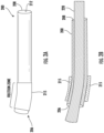
- FIG. 2A is a side view of an exemplary reshaped introducer sheath 200 with a non-straight (curved or bent) intentional friction zone about which is disposed a heat shrinkable sleeve 215.
- the introducer sheath 200 of Figure 2A is achieved by starting with a cylindrical tubing of a biocompatible material (e.g., Polypropylene (PP) or Polyethylene (PE)) having a straight (parallel to the longitudinal axis) cylindrical tubing structure with an open proximal end 206, an opposite open distal end 208, and a lumen 212 defined axially therethrough.
- a biocompatible material e.g., Polypropylene (PP) or Polyethylene (PE)
- the axial length of the heat shrink sleeve 215 in the exemplary embodiment is approximately 2 cm. Any desired axial length of the heat shrink sleeve may be selected including spanning the entire length of the introducer sheath.
- a mandrel 220 having a desired shape curvature or bend is inserted into the straight cylindrical tubing so that the curvature of the mandrel is aligned with the heat shrink sleeve 215 disposed at a desired location about the outer surface of the cylindrical tubing.
- mandrel 220 has an outer diameter in the range of approximately 0.01604" to approximately 0.01704" and a curvature/chord diameter of approximately 50.5 mm. These specified values are merely illustrative - the outer diameter of the mandrel and curvature/chord diameter of the curve may be modified, as desired.
- heating is applied at a specified temperature for a predetermined duration of time sufficient to soften, reshape, and mold the straight cylindrical tubing to conform with the curvature or bend of the mandrel 220. Simultaneously the heat causes the heat shrinkable sleeve 215 to reflow/shrink/conform about the outer surface of the reshaped or molded (e.g., curved or bent) introducer sheath 200 matching the curve of the mandrel.
- curved mandrel 220 was heated in a temperature range of approximately 320°F to approximately 330°F for a preferred duration of approximately 30 sec. to approximately 35 sec.
- the temperature and duration to which the curved mandrel 220 is heated may be selected, as desired, based on one or more factors including: (i) the material of the cylindrical tubing of the introducer sheath 200; (ii) the material of the heat shrink sleeve 215; (iii) the distance between the heating element relative to the part being heated; and (iv) the desired severity of the curve.
- pressure from the heat shrink sleeve may, but need not necessarily, result in minimal/negligible collapse (reduction) of the inner diameter of the lumen of the introducer sheath along the friction zone.
- the inner diameter for this configuration is described as having a substantially uniform (substantially unchanging) inner diameter.
- the cooled heat shrink sleeve 215 hardens thereby maintaining the curvature along the friction zone of the introducer sheath 200.
- the introducer sheath 200 nevertheless maintains its curvature or bend and hence intentional friction force imposed on the delivery system when advanced therethrough.
- a friction force is imposed between the inner wall of the introducer sheath and the outer surface of the delivery system in direct physical contact or direct engagement therewith maintaining the position of the delivery system therein.
- the proximal section along the introducer sheath in the exemplary embodiment of Figures 2A & 2B is selected as the intentional friction zone (i.e., section in which the heat shrink sleeve together with the introducer sleeve is curved or bent) so that at no time during implantation in the body does the implantable intravascular device (e.g., embolic coil) loaded in the delivery system directly physically contact or directly engage the introducer sheath (i.e., no contact between the implantable intravascular device and the inner wall of the introducer sheath within the friction zone or elsewhere). It is only the outer surface of the delivery system that directly physically contacts or directly engages only within the friction zone (controlled curvature or bend) of the inner wall of the introducer sheath.
- the implantable intravascular device e.g., embolic coil
- the heat shrink sleeve 215 is disposed so that its proximal edge is in a range of approximately 29 mm to approximately 31 mm from the proximal end 206 of the introducer sheath 200.
- the heat shrink sleeve may span the entire length of the introducer sheath or any desired portion thereof.
- the heat shrinkable sleeve disposed along the friction zone in accordance with the present invention ensures that the shape, configuration, and degree of the curvature or bend in the introducer sheath is maintained in concert with the intentional frictional force imparted between the inner wall of the introducer sheath and the outer surface of the delivery system slidable in an axial direction therethrough.
- the sleeve disposed about the outer surface of and aligned with the curve or bend in the proximal section of the introducer sheath may be made of a biocompatible metal (e.g., titanium) to prevent otherwise undesirable lessening of the curvature (reduction of the introduced friction) occurring with repeated use or runs.
- the present inventive introducer sheath is illustrated and described, by way of example, as having a single (one) friction zone (i.e., a single discrete curvature or bent section) in the proximal section of the introducer sheath; however, the introducer sheath may have more than one friction zone (each discrete friction zone comprising a curvature or bend) separated a predetermined distance in an axial direction from one another. Moreover, the one or more friction zone(s) may be located along a proximal section, a distal section, or anywhere between the proximal and distal ends of the introducer sheath. The curvature or bend of each discrete friction zone section may, but need not necessarily be, the same in dimensions.
- the curvature or bend disposed along one or more sections of the introducer sheath creates an intentional friction zone in direct physical contact/engagement with the outer surface of the delivery system.
- the embolic coil implantable intravascular device
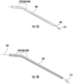
- experimental testing was performed to measure the frictional force between the introducer sheath and delivery system slidable therethrough (as shown in Figures 3A & 3B ).
- Testing was performed on an introducer sheath having a heat shrink sleeve made of polyolefin disposed about the outer surface of the introducer sheath positioned approximately 30 mm in a distal direction from the proximal end 206 of the introducer sheath.
- the heat shrink sleeve used during testing was 2 cm in length in an axial/longitudinal direction having an expanded state of approximately 0.045" and a recovered state of approximately 0.017" (representing the inner diameter of the introducer before and after heating, respectively).
- a curved mandrel having a diameter of 50.5 mm and an outer diameter of 0.01654" was inserted into the lumen of the introducer sheath until the curvature of the mandrel aligned with the heat shrink sleeve.
- Using a heat gun thermal heating at a temperature of 325°F for 30 sec. resulted in curvature or bending of the introducer sheath to match/conform with that of the mandrel simultaneously as the heat shrink sleeve shrunk about the outer surface of the curved proximal section of the introducer sheath.
- the heat shrink material of the sleeve cooled and hardened to conform to that of the curved or bent proximal section of the introducer sheath (also matching that of the withdrawn curved mandrel).
- Figure 3C shows for five different sample heat shrink sleeves each constructed using the same materials and methods with each sample being tested for 5 different runs, a graphical representation of the measured frictional force (gf) along the intentional friction zone when the delivery system engages with the inner wall of the introducer sheath of Figures 3A & 3B .
- the measured 5 gf -8 gf range of measured frictional force is deemed consistent and effectively equivalent with an average frictional force of 6.7 gf among the samples tested.
- the introducer sheath 400 retains its straight (non-bent or non-curved) (parallel to the longitudinal axis) configuration while the friction zone is created along a section thereof by intentionally reducing the inner diameter (e.g., applying to the inner wall a supplemental material). For example, an approximately 5% intentional reduction of inner diameter of the introducer sheath is created along the friction zone.
- a reflowable material 415 preferably a peelable tubing made of a heat shrink material
- a straight (non-bent, or non-curved)(i.e., parallel to the longitudinal axis extending therethrough) mandrel 420 is inserted into the lumen 412 of the straight cylindrical tubing 400.
- Heat is applied at a predetermined temperature and for a specified period of time using a heat gun or other thermal source causing reflow of the peelable heat shrink tubing 415 along the inner wall of the introducer sheath straight cylindrical tubing 400.
- the cooled peelable heat shrink tubing 415 shrinks reducing or narrowing the inner diameter of the straight cylindrical tubing 400 creating the intentional friction zone through which the delivery system 405 directly physically contacts or directly engages therewith, as depicted in Figure 4C .
- the resulting introducer may have an inner diameter reduced by approximately 5% (e.g., reduction of approximately 0.0005").
- an introducer sheath having an inner diameter (ID) 0.0165” along the friction zone the introducer sheath has an approximate 5% reduction in inner diameter (e.g., an introducer sheath having a 0.0165" inner diameter produces a resulting/reduced inner diameter of approximately 0.0157") producing a friction fit therebetween the two components.
- experimental testing was performed to measure the frictional force when the delivery system is advanced through the lumen of the introducer sheath having a configuration in Figure 4A-4C .
- Testing was performed on an exemplary introducer sheath having a peelable heat shrink tubing 2 cm in length in an axial/longitudinal direction made of polyolefin having an expanded state of approximately 0.039" and a recovered state of approximately 0.028" (representing the inner diameter of the introducer before and after heating) disposed about the outer surface of the introducer sheath positioned approximately 50mm in a distal direction from the proximal end of the introducer sheath.
- a straight or linear mandrel having an outer diameter of 0.015" was inserted into the lumen of the introducer sheath.
- the proximal section of the introducer sheath where the peelable heat shrink tubing is applied is heated to a temperature of 350°F for 30 sec. resulting in reflow of the peelable heat shrink tubing causing a reduction/narrowing in inner diameter of the lumen of the introducer sheath smaller than the outer diameter of the delivery system slidable therethrough thereby imposing the friction force therebetween.
- the proximal edge of the heat shrink tubing may be positioned to coincide or align with the proximal end of the introducer sheath and extend in a range from approximately 30 mm to approximately 100 mm in a distal direction.
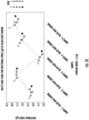
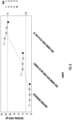
- Figure 5 is a graphical representation of the measured frictional force (gf) of three different samples in which peelable heat shrink tubing was applied to a proximal section of the inner wall of the introducer sheath that forms the intentional friction zone where the introducer sheath and delivery system directly physically contact or directly engage one another in the assembly of Figure 4C .
- the graph shows each of three samples having three trials/runs, as depicted by the distinct circular symbols provided in the legend located on the right-hand side of the graph.
- the average measured frictional force was 14.8 gf.
- the graphical representation among the multi-samples tested in Figure 5 illustrates that the consistency and repeatability of achieving a desired targeted or controlled frictional force is less than that when using the shaped (curved or bent) configuration of the introducer sheath ( Figures 2A-2B ), as shown in Figure 3C .
- Figure 6 is a graphical representational comparison of detected/measured frictional force among the following three different introducer sheath configurations: (1) first configuration: a conventional ("unaltered") introducer sheath having a straight configuration and a uniform inner diameter therethrough (i.e., absent or free of any intentional friction zone); (2) second configuration: an introducer sheath having an intentional targeted or controlled friction zone comprising a non-straight (bent or curved)(i.e., non-parallel to the longitudinal axis) section with a sleeve of heat shrinkable material disposed about the outer surface thereof, wherein the lumen of the introducer sheath has a substantially uniform inner diameter (i.e., substantially no inner diameter (ID) change); and (3) third configuration: an introducer sheath having a straight configuration producing an intentional targeted or controlled friction zone along a section of the introducer sheath (having a 0.015" inner diameter) in which the inner wall has fused thereto a heat shrink material with a reduced/narrowed
- each introducer sheath configuration is represented, while the measured/detected frictional force is represented along the y-axis.
- frictional force measurements were obtained for five different trials/runs (five data points denoted in Figure 6 by different symbols (identified in the right-hand-side legend)).
- the horizonal dashed lines depict a preferred range of frictional force from 2.5 gf (lower line) to 11 gf (upper line).
- the measured/detected level of frictional force for all five trials/runs taken with the first configuration introducer sheath was less than the preferred minimum of 2.5 gf.
- the third configuration of the introducer sheath in accordance with the present invention although not as consistent and reliable as that of the second configuration of the present inventive introducer sheath is nevertheless more advantageous than a conventional device (e.g., first configuration) free or absent of any intentional friction zone.
- any number of one or more parameters such as, but not limited to, heating parameters (e.g., temperature; duration of exposure to heat; continuous vs. intermittent application of heat); length of tubing in an axial direction; method of heating; and severity of the curve may be selected, as desired, to control the level, amount or degree of friction force imparted on the delivery system when slid through the lumen of the introducer.
- heating parameters e.g., temperature; duration of exposure to heat; continuous vs. intermittent application of heat
- length of tubing in an axial direction e.g., length of tubing in an axial direction
- method of heating e.g., a degree of friction force imparted on the delivery system when slid through the lumen of the introducer.
- the desired range of imparted frictional force is preferably between approximately 2.5 gram-force (gf) - approximately 11 gram-force (gf).
- the desired friction force imposed in the friction zone of the introducer sheath may nevertheless be overcome upon application of a sufficient axial force (pushing) applied to the proximal end of the delivery system with the implantable intravascular device loaded therein that together as a unit are slidable though the lumen of the introducer sheath during delivery to the target site in the artery.
- the imposed friction force is sufficiently strong so that when the implantable intravascular device is precisely located at the target site the position of the delivery system within the introducer sheath is held or maintained (i.e., substantially free from movement, translation or shifting) therein.
- the friction force imposed is also sufficient to prevent the delivery system from falling out from the proximal end of the introducer sheath when a flushing fluid (e.g., saline) is introduced in a retrograde direction.
- a flushing fluid e.g., saline
- Figure 7 is a graphical representation of measured frictional force with the configuration of the present inventive introducer sheath represented in Figure 3A having a non-straight (curve) configuration and a black heat shrink sleeve (with substantially no variation in inner diameter) for five different samples each sample having five different tests/runs (depicted by different symbols identified in the right-hand-side legend).
- Figure 3A having a non-straight (curve) configuration and a black heat shrink sleeve (with substantially no variation in inner diameter) for five different samples each sample having five different tests/runs (depicted by different symbols identified in the right-hand-side legend).
- Figure 8 is a graphical representational comparison among the following four different configurations of the present inventive introducer sheath: (i) first configuration - black heat shrink sleeve disposed about a curved section of the introducer sheath having a substantially uniform inner diameter; (ii) second configuration - clear heat shrink sleeve disposed about a curved section of the introducer sheath having a substantially uniform inner diameter; (iii) third configuration - mechanically bent or curved introducer sheath without any heat shrink sleeve; and (iv) fourth configuration - straight introducer sheath (no curved or bent section) with heat shrink material fused along the inner wall thereby reducing or narrowing its inner diameter along a section thereof.
- Testing was conducted with each configuration - - specifically between 2-5 samples were tested for each configuration with each sample having 5 runs/trials (as depicted by the different symbols identified in the right-hand-side legend).
- the preferred range of imposed frictional force is denoted by the two horizontal dashed lines of 2.5 gf (lower dashed line) and 11.0 gf (upper dashed line).
- the testing included five samples of each configuration, with each sample having five runs/trials.
- Each of the second and third configurations were tested using only three and two samples, respectively, with each sample having five runs/trials.
- a comparison between the first and second configurations of the introducer sheath establishes that all 25 runs/trials for all five samples having the first configuration (black heat shrink sleeve) the imposed frictional force reliably and consistently fell within the preferred range, whereas with the second configuration (clear heat shrink sleeve) several of the runs associated with each of the three samples fell outside the preferred range.
- a greater number of samples and their associated runs/trials fell outside the preferred range of imposed frictional force when using the third configuration relative to that with the second configuration.
- a still greater number of samples and their associated runs/trials fell outside the preferred range of imposed frictional force with the fourth configuration relative to that of any other configuration.
- the average imposed frictional force among the associated runs/trials of the different samples is denoted by a single diamond shape data point for that configuration.
- the present inventive universal introducer sheath has been shown and described with respect to a delivery system loaded with an embolic coil during a coil embolization procedure in the treatment of an intracranial aneurysm. It is contemplated and within the intended scope of the present invention to utilize the present inventive universal introducer sheath for other types of implantable intravascular devices used in other endovascular treatment procedures.
- the positioning, location or placement of the intentional or deliberate friction zone may be selected, as desired, anywhere along the entire length of the introducer sheath including and between the proximal and distal ends. It is also possible to vary the axial length of the friction zone. Furthermore, more than one friction zone may be provided.
- the parameters may vary to realize a targeted or controlled degree of frictional force imposed on the delivery system being slid therethrough.
- the imposed frictional force should be able to be overcome by application of an axial force when sliding the delivery system through the introducer sheath to the target site in the vessel, yet sufficient to retain/maintain/hold the delivery system in place when it has reached the target site to ensure deployment of the intravascular device at the intended site in the artery.
Landscapes
- Health & Medical Sciences (AREA)
- Life Sciences & Earth Sciences (AREA)
- General Health & Medical Sciences (AREA)
- Veterinary Medicine (AREA)
- Engineering & Computer Science (AREA)
- Biomedical Technology (AREA)
- Heart & Thoracic Surgery (AREA)
- Public Health (AREA)
- Animal Behavior & Ethology (AREA)
- Surgery (AREA)
- Anesthesiology (AREA)
- Hematology (AREA)
- Pulmonology (AREA)
- Biophysics (AREA)
- Reproductive Health (AREA)
- Vascular Medicine (AREA)
- Nuclear Medicine, Radiotherapy & Molecular Imaging (AREA)
- Medical Informatics (AREA)
- Molecular Biology (AREA)
- Neurosurgery (AREA)
- Media Introduction/Drainage Providing Device (AREA)
- Surgical Instruments (AREA)
Abstract
Description
- The present invention relates to an intervascular intervention system for delivery of an implantable intravascular device used during an endovascular treatment or procedure. In particular, the present invention is directed to an introducer sheath having an intentional friction zone to maintain in position a delivery system suitable for use with implantable intravascular devices (e.g., embolic coils) of varying outer diameter during endovascular treatment (e.g., brain aneurysm).
- Implantable intravascular devices are commonly used in the endovascular procedures or treatments of various vascular ailments, for example, brain aneurysms. A catheter is inserted into the femoral artery in patient's leg and guided by imaging navigated through the vessel to the target site in the brain where the aneurysm is located. With the distal end of the catheter properly positioned on a proximal side of the aneurysm, a microcatheter is tracked through the catheter to the proximal side of the aneurysm. A delivery and deployment system loaded with an implantable intravascular device (e.g., embolic coil) is introduced via the microcatheter to the target site. During delivery to the target site, the implantable intravascular device is secured to the delivery system, typically via a wire. When properly positioned at the target site (e.g., at the location of the aneurysm) the wire is severed or detached releasing the implantable intravascular device (e.g., embolic coil) to be deposited within the aneurysm. This process is repeated until the area of the vessel with the weakened wall is tightly packed with numerous embolic coils occluding blood flow thereto thereby preventing rupture. Severing of the embolic coil from the securement wire is typically achieved by passing of a small electrical current through the wire.
- During delivery of an implantable intravascular device to a target site within the artery or vessel, conventional intravascular intervention systems have heretofore employed various engageable mechanical configurations associated with a conventional straight introducer sheath.
US Patent No. 7,699,862 is directed to a reloadable slotted introducer sheath and vaso-occlusive device that when passed through a distal portion of a resheathing tool, the resheathing tool serves to lock in place the reloadable slotted introducer sheath and vaso-occlusive device together. Related patents (US Patent No. 8,133,252 &US Patent No. 7,819,889 ) describe an introducer sheath having a side opening defined in the outer wall radially inward to the lumen with a longitudinal slit extending from the side opening toward a distal end. These devices require complex alignment and engagement of components to operate properly. - It is desirable to develop an improved simplified introducer sheath able to maintain the position of the delivery system without the need for alignment of complex mechanical engageable components that is also universally suitable for use with coils of varying outer diameter.
- The present invention is directed to an intravascular intervention system including an introducer sheath having at least one intentional friction zone along a section thereof imposing an intentional friction force on the outer surface of a catheter shaft slidable therein. The friction zone representing a non-straight (e.g., curved or bent) section of the introducer sheath and/or a section of the introducer sheath whose inner wall has a reduced inner diameter (e.g., fused heat shrink material). During intravascular treatment, sufficient axial force may be applied to overcome the imposed intentional friction force and advance the intravascular treatment device in a distal direction to a desired target site in the artery. Once properly positioned, the imposed intentional friction force ensures that the intravascular treatment device is maintained at the desired target site when being deployed.
- Another aspect of the present invention relates to a method of manufacturing an introducer sheath of an intravascular intervention system. A straight introducer sheath having a proximal end, an opposite distal end, and a longitudinal lumen of uniform inner diameter defined therebetween is provided. Radially about an outer surface of the introducer sheath a heat shrink material is positioned. Into the longitudinal lumen of the straight introducer sheath a non-straight mandrel is inserted. Then, heat is applied at a predetermined temperature for a predetermined period of time sufficient to cause a section of the introducer sheath to be molded to include an intentional friction zone conforming to the non-straight mandrel and the heat shrink sleeve to reflow about the molded intentional friction zone forming an assembled structure. Thereafter, the non-straight mandrel is removed from the formed assembled structure including the molded introducer sheath having the intentional friction zone together with the reflow heat shrink sleeve.
- Another aspect of the present invention is directed to a method of manufacturing an introducer sheath of an intravascular intervention system by providing a straight introducer sheath having a proximal end, an opposite distal end, and a longitudinal lumen having a uniform inner diameter therebetween A heat shrink material is applied to a section of an inner wall of the straight introducer sheath and thereafter a straight mandrel is inserted into the lumen of the straight introducer sheath. Heat is applied at a predetermined temperature for a predetermined period of time sufficient to reflow the applied heat shrink material reducing the inner diameter of the longitudinal lumen along the section of the inner wall of the straight introducer sheath forming an intentional friction zone of an assembled structure. Finally, the staight mandrel is removed from the assembled structure.
- Still yet another aspect of the present invention relates to a method for using an intravascular intervention system by providing an introducer sheath having a proximal end, an opposite distal end, a longitudinal lumen with an inner diameter extending therebetween the proximal and distal ends, and an intentional friction zone along a section of the introducer sheath. Next, a catheter shaft is introduced into the longitudinal lumen of the introducer sheath. During advancement to a target position, sufficient force is applied in a distal direction on a proximal end of the catheter shaft to overcome an intentional frictional force imposed by the intentional friction zone of the introducer sheath on an outer surface of the catheter shaft. Upon reaching the target position, the catheter shaft is retained at the target position by the imposed intentional frictional force.
- The foregoing and other features of the present invention will be more readily apparent from the following detailed description and drawings illustrative of the invention wherein like reference numbers refer to similar elements throughout the several views and in which:
-
Figure 1 is a Prior Art assembly comprising a conventional intravascular intervention system including a straight introducer sheath (parallel to the longitudinal axis cylindrical tubing) together with a delivery system having an implantable intravascular device (e.g., embolic coil) loaded therein; -
Figure 2A is a side view of an exemplary embodiment of the present inventive introducer sheath having a non-straight (non-parallel to the longitudinal axis therethrough) (e.g., curved or bent section) intentional friction zone disposed along a proximal section of the introducer sheath with a heat shrink sleeve; -
Figure 2B is a longitudinal cross-sectional view of the present inventive introducer sheath ofFigure 2A by which the intentional friction zone is formed by insertion in the lumen thereof of a non-straight (curved) mandrel; -
Figure 3A is a side view of the exemplary assembly of the present inventive intravascular intervention system including the non-straight (curved or bent) intentional friction zone introducer sheath ofFigure 2A together with the delivery system having an implantable intravascular device loaded therein; -
Figure 3B is a longitudinal cross-sectional view of the present invention intravascular intervention system ofFigure 3A ; -
Figure 3C is a graphical representation of multi-sample testing of the measured frictional force between the delivery system advanced through the exemplary non-straight (curved or bent) intentional friction zone introducer sheath ofFigure 3A ; -
Figure 4A is a side view of an exemplary alternative embodiment of a present inventive straight (non-bent or non-curved) introducer sheath along a proximal section of which peelable heat shrink tubing is fused to the inner wall reducing the inner diameter forming an intentional friction zone; -
Figure 4B is a longitudinal cross-sectional view of the present inventive introducer sheath ofFigure 4A with a straight mandrel inserted in the lumen thereof in order to fuse the peelable heat shrink tubing to the inner wall of the introducer sheath; -
Figure 4C is an exemplary assembly of the reduced inner diameter friction zone introducer sheath ofFigure 4A together with a delivery system having an implantable intravascular device loaded therein; -
Figure 5 is an exemplary graphical representation of multi-sample testing of the frictional force measured between the outer surface of the delivery system and the present inventive introducer sheath ofFigure 4A ; -
Figure 6 is a graphical representation comparison of repeatability testing results of the measured frictional force for each of the present inventive introducer sheaths represented inFigures 3A &4C in comparison with that of the conventional straight introducer sheath ofFigure 1 (unaltered - without an intentional friction zone); -
Figure 7 is a graphical representation of measured frictional force for the present inventive intravascular intervention system inFigure 3A (curved introducer sheath with a heat shrink sleeve and no variation in inner diameter) for five different samples, each single sample having five different tests/runs (depicted by different symbols identified in the right-hand-side legend); and -
Figure 8 is a graphical representation comparison of measure frictional force for four different configurations: (i) a non-straight introducer sheath with a curved section intentional friction zone and black heat shrink sleeve (substantially no variation in inner diameter); (ii) a non-straight introducer sheath with a curved section intentional friction zone and clear heat shrink sleeve (substantially no variation in inner diameter); (iii) an introducer sheath with a curved or bent section intentional friction zone but no heat shrink sleeve (substantially no variation in inner diameter); and (iv) a straight introducer sheath with a peelable heat shrink tubing fused to the inner wall thereby reducing/narrowing the inner diameter as the intentional friction zone; each of the four configurations having multiple samples with each of the samples having multiple tests/runs. - In the description, the terms "distal" or "proximal" are used in the following description with respect to a position or direction relative to the treating physician or medical interventionalist. "Distal" or "distally" are a position distant from or in a direction away from the physician or interventionalist. "Proximal" or "proximally" or "proximate" are a position near or in a direction toward the physician or medical interventionist. The terms "occlusion", "clot" or "blockage" are used interchangeably.
- During an endovascular treatment procedure (e.g., coil embolization), it is desirable for the delivery and detachment/deployment system to reliably deliver and deposit the implantable intravascular device (e.g., embolic coil) at a precise location or target site (e.g., aneurysm) within a vessel or artery. The implantable intravascular device (e.g., embolic coil) is secured to the distal end of a delivery system that together as a unit are advanced to a target site in the vessel or artery via a conventional introducer sheath representing a straight (parallel to the longitudinal axis running therethrough) tubing, as illustrated in the exemplary prior art assembly of
Figure 1 .Delivery system 100 has an outer diameter of approximately 0.014". Secured to the distal end of thedelivery system 100 is a coil 105 (implantable intravascular device) with an outer diameter of approximately 0.009". Together the delivery system loaded with the coil as a unit are receivable so as to freely slide in an axial direction within the lumen of the conventional straight introducersheath 110 having an inner diameter of approximately 0.017". The conventional introducer sheath representing a straight (parallel to the longitudinal axis configuration) cylindrical tubing minimizes any direct physical contact or engagement (thus minimizing any non-intentional or undesirable friction force) between the inner wall of the lumen of the conventional straight introducer sheath and the outer surface of the delivery system slidable in a longitudinal direction therein. Any unintentional, de minimis, or negligible friction resulting from undesirable/unintentional direct physical contact between the outer surface of the delivery system and the inner wall of the lumen of the conventional introducer sheath is to be avoided or minimized as much as possible to provide as smooth a delivery of the system as possible. - Different delivery systems each having different size outer diameters are used by interventionalists to deliver embolic coils of varying outer diameter. For instance, coils having an outer diameter range of approximately 0.009" to approximately 0.016" are delivered using a delivery system that itself has an outer diameter of less than approximately 0.015". It would be advantageous to construct a universal introducer sheath suitable for use with a conventional delivery system for delivering conventional implantable intravascular devices (e.g., embolic coils) of varying size outer diameters. Opposing factors are taken into consideration when designing a universal introducer sheath. On the one hand, the inner diameter of the introducer sheath is desirably as large as possible so as to accommodate (receive and allow to freely slide in an axial direction therein) delivery systems suitable for delivery of diverse outer diameters. However, on the other hand, if the inner diameter of the lumen of the introducer sheath is made too large those delivery systems having a significantly smaller outer diameter relative thereto may undesirably shift in position when located at the target site resulting in imprecise deposit or placement of the coil in the artery. Moreover, during retrograde flushing (e.g., using saline) if not securely retained in place the delivery system may undesirably be pushed out from the proximal end of the introducer sheath. The present inventive universal introducer sheath solves the aforementioned concerns by having a sufficiently large inner diameter ranging, for example, from approximately 0.012" to approximately 0.023" for use with a delivery system able to accommodate implantable intravascular devices of different size outer diameters, yet nevertheless maintain the position of the delivery system and implantable intravascular device loaded therein (i.e., minimizing or preventing altogether shifting or falling out) by intentionally introducing a friction zone along one or more discrete sections of the introducer sheath. The intentional friction zone provided in the present inventive introducer sheath is an inexpensive and simplistic design that maintains the position of the delivery system therein while eliminating the need for proper alignment of conventional mechanical engaging mechanisms. This user-friendly simplification of the present inventive introducer sheath eliminates the dexterous physical manipulation of mechanical components requiring physical alignment in order to engage one another thus eliminating potential malfunction (e.g., unintentional failure of engagement or unintended/premature disengagement). Accordingly, the present inventive introducer sheath having one or more intentionally created friction zone(s) the imparted friction from which is overcome during advancement of the delivery system through the lumen of the introducer sheath (including passing of the distal end delivery system through and beyond the friction zone), while intentionally imparting a desired or controlled amount of frictional force on the outer surface of the delivery system to maintain or hold it in place ensuring that the implantable intravascular device loaded therein is precisely deposited at the target site (e.g., brain aneurysm) in the artery.
- The present inventive introducer sheath with at least one intentional friction zone is intended for use with a delivery system having a wide range of outer diameters (for example, in a range of approximately 0.0136" to approximately 0.0156") suitable for use with various implantable intravascular devices having different size outer diameters (for example, ranging from approximately 0.009" to approximately 0.016").
- Conventional introducer sheaths (as depicted in
Figure 1 ) represent cylindrical tubing having a straight (parallel to the longitudinal axis extending therethrough) configuration to minimize or avoid altogether any undesirable friction or direct physical contact/engagement between the outer surface of the delivery system and the inner wall of the lumen of the introducer sheath extending in an axial/longitudinal direction therethrough. In contradistinction to such conventional device, the present invention deliberately and intentionally introduces a friction zone along a desired section (e.g., along a proximal and/or distal section) of the introducer sheath to intentionally impose a targeted or controlled friction force on the outer surface of the delivery system as it is slid through therethrough. Intentional introduction of the friction zone along the present inventive introducer sheath may be achieved in a number of ways, of which each design may be used independently of or simultaneously with one another. - For the purpose of this invention, the term "proximal section" is herein defined to include any axial section or portion of the introducer sheath between a midway point (i.e., midway between an open proximal end and an opposite open distal end) and the proximal end/tip of the introducer sheath. In a preferred embodiment, the proximal section may, but doesn't necessarily, include the midway point and/or the proximal end/tip of the introducer sheath. Similarly, the term "distal section" is hereinafter defined to include any axial section or portion of the introducer sheath between a midway point (i.e., midway between an open proximal end and an opposite open distal end) and the distal end/tip of the introducer sheath. In a preferred embodiment, the distal section may, but doesn't necessarily, include the midway point and/or the distal end/tip of the introducer sheath. As previously noted, the intentional friction zone may be disposed anywhere (e.g., proximal section, distal section and/or anywhere between the proximal and distal ends) along the introducer sheath and may include more than one friction zone.
- One exemplary way to create an intentional friction zone in the present inventive introducer sheath is to deliberately alter (e.g., curving or bending) the shape of straight cylindrical tubing so that a friction zone section thereof is no longer straight (i.e., non-straight). The term "non-straight" when describing the present inventive introducer sheath is referring to the friction zone thereof. Outside of the non-straight friction zone, the remaining unaltered sections of the introducer sheath remains straight. The controlled alteration (e.g., curving or bending) of the shape of the altered non-straight intentional friction zone of the introducer sheath increases the direct contact surface area between the inner wall along the friction zone of the introducer sheath and the outer surface of the delivery system thereby intentionally imparting a desired amount of friction between the two components.
- The term "curvature/curve/curved/curving" or "bend/bent/bending" when describing the intentional friction zone created along the altered non-straight introducer sheath is expressly defined for the purposes herein to be a non-zero angle relative to a longitudinal axis therethrough. In other words, the non-straight (curved or bent) portion comprising the intentional friction zone is non-parallel to the longitudinal axis through the introducer sheath. Selection of a desired curvature imposes or induces a controlled or targeted friction force on the outer surface of the delivery system during advancement through the lumen of the introducer sheath.
- When selecting the controlled or targeted curvature or bend in the introducer sheath two competing broad interests are satisfied. On the one hand, the targeted or controlled imposed intentional frictional force is able to be overcome upon application of a sufficient axial pushing force on a proximal end of the delivery system in a distal direction during advancement of the implantable intravascular device to a target site in the artery. While, on the other hand, the targeted or controlled frictional force induced or imparted is sufficient to ensure that the delivery system is held in place (i.e., prevent or minimize shifting, movement, or translation) within the introducer sheath once the implantable intravascular device is precisely positioned at the target site in the artery. A preferred range of targeted or controlled intentional friction force imposed by the non-straight (curved or bent) intentional friction zone of the introducer sheath on the outer surface of the delivery system is preferably in a range between approximately 2.5 gf to approximately 11 gf. Any range of intentional friction force may be imposed, induced or established, as desired, taking these competing factors into consideration.
- The outer surface of the delivery system intentionally directly physically contacts or directly engages with the inner wall of the introducer sheath within the non-straight intentional friction zone (curved or bent section) thereby imparting a controlled or targeted frictional force that maintains the delivery system in place relative to the introducer sheath once the implantable intravascular device has been precisely located at the target site in the artery.
Figure 2A is a side view of an exemplary reshapedintroducer sheath 200 with a non-straight (curved or bent) intentional friction zone about which is disposed a heat shrinkablesleeve 215. - The
introducer sheath 200 ofFigure 2A is achieved by starting with a cylindrical tubing of a biocompatible material (e.g., Polypropylene (PP) or Polyethylene (PE)) having a straight (parallel to the longitudinal axis) cylindrical tubing structure with an openproximal end 206, an opposite opendistal end 208, and alumen 212 defined axially therethrough. Asleeve 215 made of a biocompatible (medical grade) heat shrinkable material, for example, Polytetrafluoroethylene (PTFE), Fluorinated ethylene propylene (FEP), or Polyether EtherKetone (PEEK) is positioned at a desired section (e.g., proximal section) about the outer surface of the straight cylindrical tubing. The axial length of theheat shrink sleeve 215 in the exemplary embodiment is approximately 2 cm. Any desired axial length of the heat shrink sleeve may be selected including spanning the entire length of the introducer sheath. - Referring to the longitudinal cross-sectional view of
Figure 2B , amandrel 220 having a desired shape curvature or bend is inserted into the straight cylindrical tubing so that the curvature of the mandrel is aligned with theheat shrink sleeve 215 disposed at a desired location about the outer surface of the cylindrical tubing. In the exemplary embodiment ofFigure 2B ,mandrel 220 has an outer diameter in the range of approximately 0.01604" to approximately 0.01704" and a curvature/chord diameter of approximately 50.5 mm. These specified values are merely illustrative - the outer diameter of the mandrel and curvature/chord diameter of the curve may be modified, as desired. - Exposure to heat causes the
introducer sheath 200 to mold/form/bend to match the curvature of the mandrel. Simultaneously,heat shrink sleeve 215 shrinks/conforms about the outer surface of theintroducer sheath 200 with a curvature also matching that of the mandrel. When the heat is removed and the curved mandrel is withdrawn from the molded/shapedintroducer sheath 200heat shrink sleeve 215 cools and hardens about the introducer sheath thus maintaining the curvature or bend matching that of the curved mandrel. - Specifically, heating is applied at a specified temperature for a predetermined duration of time sufficient to soften, reshape, and mold the straight cylindrical tubing to conform with the curvature or bend of the
mandrel 220. Simultaneously the heat causes the heat shrinkablesleeve 215 to reflow/shrink/conform about the outer surface of the reshaped or molded (e.g., curved or bent)introducer sheath 200 matching the curve of the mandrel. In the exemplary embodiment ofFigure 2B ,curved mandrel 220 was heated in a temperature range of approximately 320°F to approximately 330°F for a preferred duration of approximately 30 sec. to approximately 35 sec. The temperature and duration to which thecurved mandrel 220 is heated may be selected, as desired, based on one or more factors including: (i) the material of the cylindrical tubing of theintroducer sheath 200; (ii) the material of theheat shrink sleeve 215; (iii) the distance between the heating element relative to the part being heated; and (iv) the desired severity of the curve. When heated, pressure from the heat shrink sleeve may, but need not necessarily, result in minimal/negligible collapse (reduction) of the inner diameter of the lumen of the introducer sheath along the friction zone. Any such reduction or change in inner diameter is so negligible or de minimis as to be inconsequential and hence, despite such possibility, hereinafter the inner diameter for this configuration is described as having a substantially uniform (substantially unchanging) inner diameter. Following turning off the heat and withdrawing of thecurved mandrel 220, the cooledheat shrink sleeve 215 hardens thereby maintaining the curvature along the friction zone of theintroducer sheath 200. As a result of theheat shrink sleeve 215, despite repeated runs or turns of the delivery system therethrough, theintroducer sheath 200 nevertheless maintains its curvature or bend and hence intentional friction force imposed on the delivery system when advanced therethrough. Having created along the introducer sheath the friction zone in which at least a portion thereof is non-straight (non-parallel to the longitudinal axis extending therethrough)(e.g., curved or bent) a friction force is imposed between the inner wall of the introducer sheath and the outer surface of the delivery system in direct physical contact or direct engagement therewith maintaining the position of the delivery system therein. - The proximal section along the introducer sheath in the exemplary embodiment of
Figures 2A & 2B is selected as the intentional friction zone (i.e., section in which the heat shrink sleeve together with the introducer sleeve is curved or bent) so that at no time during implantation in the body does the implantable intravascular device (e.g., embolic coil) loaded in the delivery system directly physically contact or directly engage the introducer sheath (i.e., no contact between the implantable intravascular device and the inner wall of the introducer sheath within the friction zone or elsewhere). It is only the outer surface of the delivery system that directly physically contacts or directly engages only within the friction zone (controlled curvature or bend) of the inner wall of the introducer sheath. In the exemplary embodiment ofFigure 2A , theheat shrink sleeve 215 is disposed so that its proximal edge is in a range of approximately 29 mm to approximately 31 mm from theproximal end 206 of theintroducer sheath 200. As previously mentioned, the heat shrink sleeve may span the entire length of the introducer sheath or any desired portion thereof. - It is noted that the mere physical curving or bending of an otherwise straight (linear) cylindrical tubing of the conventional introducer sheath without the use of the heat shrink sleeve in accordance with the present invention is less satisfactory for the intended purpose of creating the present inventive controlled or targeted friction zone. With each run (i.e., repeated sliding of the delivery system in an axial direction within the lumen of the introducer sheath) the degree of friction therebetween lessens as a result of lessening of the curvature. Whereas, the heat shrinkable sleeve disposed along the friction zone in accordance with the present invention (
Figure 2A ) ensures that the shape, configuration, and degree of the curvature or bend in the introducer sheath is maintained in concert with the intentional frictional force imparted between the inner wall of the introducer sheath and the outer surface of the delivery system slidable in an axial direction therethrough. Instead of using a heat shrink material the sleeve disposed about the outer surface of and aligned with the curve or bend in the proximal section of the introducer sheath may be made of a biocompatible metal (e.g., titanium) to prevent otherwise undesirable lessening of the curvature (reduction of the introduced friction) occurring with repeated use or runs. - Moreover, the present inventive introducer sheath is illustrated and described, by way of example, as having a single (one) friction zone (i.e., a single discrete curvature or bent section) in the proximal section of the introducer sheath; however, the introducer sheath may have more than one friction zone (each discrete friction zone comprising a curvature or bend) separated a predetermined distance in an axial direction from one another. Moreover, the one or more friction zone(s) may be located along a proximal section, a distal section, or anywhere between the proximal and distal ends of the introducer sheath. The curvature or bend of each discrete friction zone section may, but need not necessarily be, the same in dimensions.
- Accordingly, the curvature or bend disposed along one or more sections of the introducer sheath creates an intentional friction zone in direct physical contact/engagement with the outer surface of the delivery system. During advancement to the target site in the vessel, when loaded in the delivery system, preferably the embolic coil (implantable intravascular device) never directly physically contacts or directly physically engages with the friction zone or any other region of the inner wall of the introducer sheath.
- By way of illustrative example, experimental testing was performed to measure the frictional force between the introducer sheath and delivery system slidable therethrough (as shown in
Figures 3A & 3B ). Testing was performed on an introducer sheath having a heat shrink sleeve made of polyolefin disposed about the outer surface of the introducer sheath positioned approximately 30 mm in a distal direction from theproximal end 206 of the introducer sheath. The heat shrink sleeve used during testing was 2 cm in length in an axial/longitudinal direction having an expanded state of approximately 0.045" and a recovered state of approximately 0.017" (representing the inner diameter of the introducer before and after heating, respectively). With the heat shrink sleeve properly positioned at the desired proximal section along the outer surface of the introducer sheath, a curved mandrel having a diameter of 50.5 mm and an outer diameter of 0.01654" was inserted into the lumen of the introducer sheath until the curvature of the mandrel aligned with the heat shrink sleeve. Using a heat gun thermal heating at a temperature of 325°F for 30 sec. resulted in curvature or bending of the introducer sheath to match/conform with that of the mandrel simultaneously as the heat shrink sleeve shrunk about the outer surface of the curved proximal section of the introducer sheath. Following cut off of the heat and withdraw of the mandrel from the introducer sheath the heat shrink material of the sleeve cooled and hardened to conform to that of the curved or bent proximal section of the introducer sheath (also matching that of the withdrawn curved mandrel). -
Figure 3C shows for five different sample heat shrink sleeves each constructed using the same materials and methods with each sample being tested for 5 different runs, a graphical representation of the measured frictional force (gf) along the intentional friction zone when the delivery system engages with the inner wall of the introducer sheath ofFigures 3A & 3B . In light of the fact that the parts tested were hand-made, the measured 5 gf -8 gf range of measured frictional force is deemed consistent and effectively equivalent with an average frictional force of 6.7 gf among the samples tested. - In the previous described configuration (
Figures 3A & 3B ) employing a controlled or targeted curve or bend along a proximal section of the present inventive introducer sheath as the intentional friction zone the inner diameter of the introducer sheath is substantially uniform from the proximal to the distal end of the tubing including along the non-straight intentional friction zone. The inner diameter is described as substantially uniform because pressure from the heat shrink sleeve when heated may, but need not necessarily, result in unintended de minimis or negligible collapse (reduction) of the inner diameter of the lumen in the friction zone. In an alternative design shown inFigures 4A-4C , theintroducer sheath 400 retains its straight (non-bent or non-curved) (parallel to the longitudinal axis) configuration while the friction zone is created along a section thereof by intentionally reducing the inner diameter (e.g., applying to the inner wall a supplemental material). For example, an approximately 5% intentional reduction of inner diameter of the introducer sheath is created along the friction zone. Specifically, a reflowable material 415 (preferably a peelable tubing made of a heat shrink material) is fused to the inner wall along a section of the straightcylindrical tubing 400 between its proximal and distal ends, 406, 408, respectively (Figure 4A ). Referring toFigure 4B , a straight (non-bent, or non-curved)(i.e., parallel to the longitudinal axis extending therethrough) mandrel 420 is inserted into thelumen 412 of the straightcylindrical tubing 400. Heat is applied at a predetermined temperature and for a specified period of time using a heat gun or other thermal source causing reflow of the peelableheat shrink tubing 415 along the inner wall of the introducer sheath straightcylindrical tubing 400. After removal of the heat and mandrel, the cooled peelableheat shrink tubing 415 shrinks reducing or narrowing the inner diameter of the straightcylindrical tubing 400 creating the intentional friction zone through which thedelivery system 405 directly physically contacts or directly engages therewith, as depicted inFigure 4C . For instance, the resulting introducer may have an inner diameter reduced by approximately 5% (e.g., reduction of approximately 0.0005"). As an illustrative example, for a delivery system having an outer diameter (OD) of 0.0152" and an introducer sheath having an inner diameter (ID) 0.0165", along the friction zone the introducer sheath has an approximate 5% reduction in inner diameter (e.g., an introducer sheath having a 0.0165" inner diameter produces a resulting/reduced inner diameter of approximately 0.0157") producing a friction fit therebetween the two components. - By way of illustrative example, experimental testing was performed to measure the frictional force when the delivery system is advanced through the lumen of the introducer sheath having a configuration in
Figure 4A-4C . Testing was performed on an exemplary introducer sheath having a peelable heat shrinktubing 2 cm in length in an axial/longitudinal direction made of polyolefin having an expanded state of approximately 0.039" and a recovered state of approximately 0.028" (representing the inner diameter of the introducer before and after heating) disposed about the outer surface of the introducer sheath positioned approximately 50mm in a distal direction from the proximal end of the introducer sheath. With heat shrink sleeve properly positioned at the desired proximal section along the outer surface of the introducer sheath, a straight or linear mandrel having an outer diameter of 0.015" was inserted into the lumen of the introducer sheath. Using a heat gun or other thermal source, the proximal section of the introducer sheath where the peelable heat shrink tubing is applied is heated to a temperature of 350°F for 30 sec. resulting in reflow of the peelable heat shrink tubing causing a reduction/narrowing in inner diameter of the lumen of the introducer sheath smaller than the outer diameter of the delivery system slidable therethrough thereby imposing the friction force therebetween. The precise parameter ranges were for the specific example with which the tests were run, however, these parameter ranges are non-limiting and may be varied, as desired. For example, the proximal edge of the heat shrink tubing may be positioned to coincide or align with the proximal end of the introducer sheath and extend in a range from approximately 30 mm to approximately 100 mm in a distal direction. -
Figure 5 is a graphical representation of the measured frictional force (gf) of three different samples in which peelable heat shrink tubing was applied to a proximal section of the inner wall of the introducer sheath that forms the intentional friction zone where the introducer sheath and delivery system directly physically contact or directly engage one another in the assembly ofFigure 4C . The graph shows each of three samples having three trials/runs, as depicted by the distinct circular symbols provided in the legend located on the right-hand side of the graph. Among the samples tested the average measured frictional force was 14.8 gf. The graphical representation among the multi-samples tested inFigure 5 illustrates that the consistency and repeatability of achieving a desired targeted or controlled frictional force is less than that when using the shaped (curved or bent) configuration of the introducer sheath (Figures 2A-2B ), as shown inFigure 3C . -
Figure 6 is a graphical representational comparison of detected/measured frictional force among the following three different introducer sheath configurations: (1) first configuration: a conventional ("unaltered") introducer sheath having a straight configuration and a uniform inner diameter therethrough (i.e., absent or free of any intentional friction zone); (2) second configuration: an introducer sheath having an intentional targeted or controlled friction zone comprising a non-straight (bent or curved)(i.e., non-parallel to the longitudinal axis) section with a sleeve of heat shrinkable material disposed about the outer surface thereof, wherein the lumen of the introducer sheath has a substantially uniform inner diameter (i.e., substantially no inner diameter (ID) change); and (3) third configuration: an introducer sheath having a straight configuration producing an intentional targeted or controlled friction zone along a section of the introducer sheath (having a 0.015" inner diameter) in which the inner wall has fused thereto a heat shrink material with a reduced/narrowed inner diameter relative to the inner diameter outside the friction zone. Along the x-axis each introducer sheath configuration is represented, while the measured/detected frictional force is represented along the y-axis. For each of the three introducer sheath configurations frictional force measurements were obtained for five different trials/runs (five data points denoted inFigure 6 by different symbols (identified in the right-hand-side legend)). The horizonal dashed lines depict a preferred range of frictional force from 2.5 gf (lower line) to 11 gf (upper line). As is evident from the graphical representational comparison, the measured/detected level of frictional force for all five trials/runs taken with the first configuration introducer sheath was less than the preferred minimum of 2.5 gf. Such result for this conventional introducer sheath is expected since intentional or deliberate friction between the components is to be avoided. Among the remaining two introducer sheath configurations of the present invention having an intentional friction zone the best results were achieved with the second configuration. Results of the measured/detected frictional force for the five trial/runs using the third configuration introducer sheath is an improvement over that of the first configuration but not as consistent as when using the second configuration. That is, when testing the frictional force imparted using the third configuration introducer sheath only one of the five trials/runs fell within the preferred range of approximately 2.5 gf to approximately 11 gf, the remaining four runs undesirably imposed a friction force greater than the preferred maximum value of 11 gf. In such cases where the friction force exceeded 11 gf, use of the delivery system to advance the implantable intravascular device (e.g., embolic coil) to the target site in the artery may undesirably require the application of too large an axial force to overcome the friction force. Thus, the third configuration of the introducer sheath in accordance with the present invention although not as consistent and reliable as that of the second configuration of the present inventive introducer sheath is nevertheless more advantageous than a conventional device (e.g., first configuration) free or absent of any intentional friction zone. - Any number of one or more parameters such as, but not limited to, heating parameters (e.g., temperature; duration of exposure to heat; continuous vs. intermittent application of heat); length of tubing in an axial direction; method of heating; and severity of the curve may be selected, as desired, to control the level, amount or degree of friction force imparted on the delivery system when slid through the lumen of the introducer. Regardless of the configuration used to create the friction zone (e.g., non-straight shape vs. reduction in inner diameter), the desired range of imparted frictional force is preferably between approximately 2.5 gram-force (gf) - approximately 11 gram-force (gf). In more broad terms, on the one hand, the desired friction force imposed in the friction zone of the introducer sheath may nevertheless be overcome upon application of a sufficient axial force (pushing) applied to the proximal end of the delivery system with the implantable intravascular device loaded therein that together as a unit are slidable though the lumen of the introducer sheath during delivery to the target site in the artery. While, on the other hand, the imposed friction force is sufficiently strong so that when the implantable intravascular device is precisely located at the target site the position of the delivery system within the introducer sheath is held or maintained (i.e., substantially free from movement, translation or shifting) therein. Moreover, the friction force imposed is also sufficient to prevent the delivery system from falling out from the proximal end of the introducer sheath when a flushing fluid (e.g., saline) is introduced in a retrograde direction.
-
Figure 7 is a graphical representation of measured frictional force with the configuration of the present inventive introducer sheath represented inFigure 3A having a non-straight (curve) configuration and a black heat shrink sleeve (with substantially no variation in inner diameter) for five different samples each sample having five different tests/runs (depicted by different symbols identified in the right-hand-side legend). Among the 25 total runs the extremely high degree of reliability and predictability of imposed frictional force within the preferred range using the second configuration introducer sheath is evident. -
Figure 8 is a graphical representational comparison among the following four different configurations of the present inventive introducer sheath: (i) first configuration - black heat shrink sleeve disposed about a curved section of the introducer sheath having a substantially uniform inner diameter; (ii) second configuration - clear heat shrink sleeve disposed about a curved section of the introducer sheath having a substantially uniform inner diameter; (iii) third configuration - mechanically bent or curved introducer sheath without any heat shrink sleeve; and (iv) fourth configuration - straight introducer sheath (no curved or bent section) with heat shrink material fused along the inner wall thereby reducing or narrowing its inner diameter along a section thereof. Testing was conducted with each configuration - - specifically between 2-5 samples were tested for each configuration with each sample having 5 runs/trials (as depicted by the different symbols identified in the right-hand-side legend). The preferred range of imposed frictional force is denoted by the two horizontal dashed lines of 2.5 gf (lower dashed line) and 11.0 gf (upper dashed line). For each of the first and fourth configurations, the testing included five samples of each configuration, with each sample having five runs/trials. Each of the second and third configurations were tested using only three and two samples, respectively, with each sample having five runs/trials. - A comparison between the first and second configurations of the introducer sheath establishes that all 25 runs/trials for all five samples having the first configuration (black heat shrink sleeve) the imposed frictional force reliably and consistently fell within the preferred range, whereas with the second configuration (clear heat shrink sleeve) several of the runs associated with each of the three samples fell outside the preferred range. A greater number of samples and their associated runs/trials fell outside the preferred range of imposed frictional force when using the third configuration relative to that with the second configuration. A still greater number of samples and their associated runs/trials fell outside the preferred range of imposed frictional force with the fourth configuration relative to that of any other configuration. For each of the four configurations, the average imposed frictional force among the associated runs/trials of the different samples is denoted by a single diamond shape data point for that configuration. Once again from this line representing the average imposed frictional force it is evident that the most reliable and consistent imposed frictional force falling within the preferred range is provided by the first configuration.
- The present inventive universal introducer sheath has been shown and described with respect to a delivery system loaded with an embolic coil during a coil embolization procedure in the treatment of an intracranial aneurysm. It is contemplated and within the intended scope of the present invention to utilize the present inventive universal introducer sheath for other types of implantable intravascular devices used in other endovascular treatment procedures. The positioning, location or placement of the intentional or deliberate friction zone may be selected, as desired, anywhere along the entire length of the introducer sheath including and between the proximal and distal ends. It is also possible to vary the axial length of the friction zone. Furthermore, more than one friction zone may be provided. In selection of the placement, number and dimensions of the friction zone the parameters may vary to realize a targeted or controlled degree of frictional force imposed on the delivery system being slid therethrough. As previously noted, the imposed frictional force should be able to be overcome by application of an axial force when sliding the delivery system through the introducer sheath to the target site in the vessel, yet sufficient to retain/maintain/hold the delivery system in place when it has reached the target site to ensure deployment of the intravascular device at the intended site in the artery.
- Thus, while there have been shown, described, and pointed out fundamental novel features of the invention as applied to a preferred embodiment thereof, it will be understood that various omissions, substitutions, and changes in the form and details of the systems/devices illustrated, and in their operation, may be made by those skilled in the art without departing from the spirit and scope of the invention. For example, it is expressly intended that all combinations of those elements and/or steps that perform substantially the same function, in substantially the same way, to achieve the same results be within the scope of the invention. Substitutions of elements from one described embodiment to another are also fully intended and contemplated. It is also to be understood that the drawings are not necessarily drawn to scale, but that they are merely conceptual in nature. It is the intention, therefore, to be limited only as indicated by the scope of the claims appended hereto.
- Every issued patent, pending patent application, publication, journal article, book or any other reference cited herein is each incorporated by reference in their entirety.
-
- 1. A method for using an intravascular intervention system comprising the steps of:
- providing an introducer sheath having a proximal end, an opposite distal end, a longitudinal lumen with an inner diameter extending therebetween the proximal and distal ends, and an intentional friction zone along a section of the introducer sheath;
- introducing a catheter shaft into the longitudinal lumen of the introducer sheath; and
- applying sufficient force in a distal direction on a proximal end of the catheter shaft to overcome an intentional frictional force imposed by the intentional friction zone of the introducer sheath on an outer surface of the catheter shaft during advancement to a target position;
- when reaching the target position, the catheter shaft being retained at the target position by the imposed intentional frictional force.
- 2. The method in accordance with
aspect 1, wherein the intentional frictional force imposed on the outer surface of the catheter shaft in a range of approximately 2.5 gf to approximately 11 gf when slid therethrough. - 3. The method in accordance with
aspect 1, wherein the intentional friction zone is a non-straight section of the introducer sheath and/or a section of the introducer sheath of reduced inner diameter. - 4. The method in accordance with
aspect 3, wherein the non-straight section is a curved or bent section. - 5. The method in accordance with
aspect 3, wherein the section of the introducer sheath having the reduced inner diameter has a heat shrink material disposed along an inner wall of the introducer sheath. - 6. The method in accordance with
aspect 1, wherein the imposed intentional frictional force on an outer surface of the catheter shaft in a range of approximately 2.5 gf to approximately 11 gf when slid therethrough.
Claims (14)
- An intravascular intervention system comprising:
an introducer sheath having a proximal end, an opposite distal end and a longitudinal lumen defined therethrough forming an inner wall of the introducer sheath; the introducer sheath having an intentional friction zone along a section thereof. - The intravascular intervention system in accordance with claim 1, further comprising a catheter shaft slidable through the longitudinal lumen of the introducer sheath; wherein the intentional friction zone imposes an intentional frictional force on an outer surface of the catheter shaft in a range of approximately 2.5 gf to approximately 11 gf when slid therethrough.
- The intravascular intervention system in accordance with claim 1, wherein the intentional frictional zone is a non-straight section of the introducer sheath with a sleeve disposed about an outer surface of the non-straight section of the introducer sheath.
- The intravascular intervention system in accordance with claim 3, wherein the non-straight section of the introducer sheath is curved or bent.
- The intravascular intervention system in accordance with claim 3, wherein the intentional friction zone is disposed along a proximal section and/or a distal section of the introducer sheath.
- The intravascular intervention system in accordance with claim 3, wherein an inner diameter of the longitudinal lumen is substantially uniform from the proximal end to the opposite distal end including along the intentional friction zone.
- The intravascular intervention system in accordance with claim 3, wherein the sleeve is made of a heat shrink material or metal.
- The intravascular intervention system in accordance with claim 1, wherein in the intentional friction zone a heat shrink material is fused to the inner wall of the introducer sheath reducing an inner diameter of the longitudinal lumen relative to the inner diameter of the longitudinal lumen absent the heat shrink material outside the intentional friction zone.
- A method of manufacturing an introducer sheath of an intravascular intervention system, the method comprising the steps of:providing a straight introducer sheath having a proximal end, an opposite distal end, and a longitudinal lumen of uniform inner diameter defined therebetween;positioning a heat shrink sleeve radially about an outer surface of the introducer sheath;inserting into the longitudinal lumen of the straight introducer sheath a non-straight mandrel;heating at a predetermined temperature for a predetermined period of time sufficient to cause a section of the introducer sheath to be molded to include an intentional friction zone conforming to the non-straight mandrel and the heat shrink sleeve to reflow about the molded intentional friction zone forming an assembled structure; andremoving the non-straight mandrel from the formed assembled structure including the molded introducer sheath having the intentional friction zone together with the reflow heat shrink sleeve.
- The method in accordance with claim 9. wherein the non-straight mandrel has at least one curved section that is aligned with the heat shrink sleeve; and the molded intentional friction zone conforms to the at least one curved section.
- The method in accordance with claim 9, wherein the molded intentional friction zone is disposed along one of a proximal section and/or a distal section of the introducer sheath.
- The method in accordance with claim 9, wherein the inner diameter of the longitudinal lumen is uniform from the proximal end to the opposite distal end including along the molded intentional friction zone of the introducer sheath.
- A method of manufacturing an introducer sheath of an intravascular intervention system, the method comprising the steps of:providing a straight introducer sheath having a proximal end, an opposite distal end, and a longitudinal lumen having a uniform inner diameter therebetween;applying a heat shrink material to a section of an inner wall of the straight introducer sheath;inserting into the lumen of the straight introducer sheath a straight mandrel;heating at a predetermined temperature for a predetermined period of time sufficient to reflow the applied heat shrink material reducing an inner diameter of the longitudinal lumen along the section of the inner wall of the straight introducer sheath forming an intentional friction zone of an assembled structure relative to the inner diameter of the longitudinal lumen absent the heat shrink material outside the intentional friction zone; andremoving the staight mandrel from the assembled structure.
- The method in accordance with claim 13, wherein the heat shrink material is peelable heat shrink tubing.
Applications Claiming Priority (1)
| Application Number | Priority Date | Filing Date | Title |
|---|---|---|---|
| US17/482,373 US12369920B2 (en) | 2021-09-22 | 2021-09-22 | Introducer sheath having an intentional friction zone to hold in position a delivery system suitable for implantable intravascular devices |
Publications (1)
| Publication Number | Publication Date |
|---|---|
| EP4154934A1 true EP4154934A1 (en) | 2023-03-29 |
Family
ID=83400583
Family Applications (1)
| Application Number | Title | Priority Date | Filing Date |
|---|---|---|---|
| EP22196746.6A Pending EP4154934A1 (en) | 2021-09-22 | 2022-09-21 | An introducer sheath having an intentional friction zone to hold in position a delivery system suitable for implantable intravascular devices |
Country Status (5)
| Country | Link |
|---|---|
| US (1) | US12369920B2 (en) |
| EP (1) | EP4154934A1 (en) |
| JP (1) | JP2023046309A (en) |
| KR (1) | KR20230042662A (en) |
| CN (1) | CN115920205A (en) |
Citations (10)
| Publication number | Priority date | Publication date | Assignee | Title |
|---|---|---|---|---|
| US3149186A (en) * | 1959-06-04 | 1964-09-15 | Baxter Don Inc | Method for making a catheter |
| US20040104512A1 (en) * | 2002-12-03 | 2004-06-03 | Scimed Life Systems, Inc. | Method for forming catheter curves |
| US7699862B2 (en) | 2005-01-25 | 2010-04-20 | Micrus Corporation | Resheathing tool |
| US7819889B2 (en) | 2002-09-20 | 2010-10-26 | Codman & Shurtleff, Inc. | Detachable introducer for a medical device deployment system |
| US8133252B2 (en) | 2002-09-20 | 2012-03-13 | Codman & Shurtleff, Inc. | Reattachable introducer for a medical device deployment system |
| US20140194822A1 (en) * | 2013-01-08 | 2014-07-10 | Biosense Webster (Israel), Ltd. | Catheter sheath introducer with directional retention damper |
| US20150272735A1 (en) * | 2014-03-26 | 2015-10-01 | Biotronik Ag | Catheter device for minimally invasive implantation |
| US20200288952A1 (en) * | 2019-03-11 | 2020-09-17 | Spiration, Inc. D/B/A Olympus Respiratory America | Sheath location indicator and overextension preventer |
| CN112604126A (en) * | 2020-11-30 | 2021-04-06 | 东莞科威医疗器械有限公司 | Medical variable-diameter intubation tube forming process and intubation tube |
| US20210205577A1 (en) * | 2018-06-01 | 2021-07-08 | Covidien Lp | Flexible tip catheter |
Family Cites Families (113)
| Publication number | Priority date | Publication date | Assignee | Title |
|---|---|---|---|---|
| US6408214B1 (en) * | 2000-07-11 | 2002-06-18 | Medtronic, Inc. | Deflectable tip catheter for CS pacing |
| US20090143808A1 (en) | 2001-04-24 | 2009-06-04 | Houser Russell A | Guided Tissue Cutting Device, Method of Use and Kits Therefor |
| US8715312B2 (en) | 2001-07-20 | 2014-05-06 | Microvention, Inc. | Aneurysm treatment device and method of use |
| US8252040B2 (en) | 2001-07-20 | 2012-08-28 | Microvention, Inc. | Aneurysm treatment device and method of use |
| CN1301692C (en) | 2002-09-18 | 2007-02-28 | 阿勒根公司 | Devices for Ocular Implant Introduction |
| US20050165366A1 (en) * | 2004-01-28 | 2005-07-28 | Brustad John R. | Medical tubing having variable characteristics and method of making same |
| US7371228B2 (en) | 2003-09-19 | 2008-05-13 | Medtronic Vascular, Inc. | Delivery of therapeutics to treat aneurysms |
| US9308382B2 (en) | 2004-06-10 | 2016-04-12 | Medtronic Urinary Solutions, Inc. | Implantable pulse generator systems and methods for providing functional and/or therapeutic stimulation of muscles and/or nerves and/or central nervous system tissue |
| US9655633B2 (en) | 2004-09-10 | 2017-05-23 | Penumbra, Inc. | System and method for treating ischemic stroke |
| US20060089637A1 (en) | 2004-10-14 | 2006-04-27 | Werneth Randell L | Ablation catheter |
| US8562672B2 (en) | 2004-11-19 | 2013-10-22 | Medtronic, Inc. | Apparatus for treatment of cardiac valves and method of its manufacture |
| US9636115B2 (en) | 2005-06-14 | 2017-05-02 | Stryker Corporation | Vaso-occlusive delivery device with kink resistant, flexible distal end |
| CN101309651B (en) | 2005-06-20 | 2011-12-07 | 麦德托尼克消融前沿有限公司 | Ablation catheter |
| CA2630021C (en) | 2005-11-17 | 2013-08-13 | Microvention, Inc. | Three-dimensional complex coil |
| US9757260B2 (en) | 2006-03-30 | 2017-09-12 | Medtronic Vascular, Inc. | Prosthesis with guide lumen |
| US9615832B2 (en) | 2006-04-07 | 2017-04-11 | Penumbra, Inc. | Aneurysm occlusion system and method |
| JP2010500917A (en) | 2006-06-15 | 2010-01-14 | マイクロベンション, インコーポレイテッド | Embolization device composed of expandable polymer |
| AU2008345590B2 (en) | 2007-12-21 | 2014-10-30 | Microvention, Inc. | Hydrogel filaments for biomedical uses |
| US8974518B2 (en) | 2008-03-25 | 2015-03-10 | Medtronic Vascular, Inc. | Eversible branch stent-graft and deployment method |
| EP2192947A1 (en) | 2008-04-30 | 2010-06-09 | Medtronic, Inc. | Techniques for placing medical leads for electrical stimulation of nerve tissue |
| US8070694B2 (en) | 2008-07-14 | 2011-12-06 | Medtronic Vascular, Inc. | Fiber based medical devices and aspiration catheters |
| US8333796B2 (en) | 2008-07-15 | 2012-12-18 | Penumbra, Inc. | Embolic coil implant system and implantation method |
| US8721714B2 (en) | 2008-09-17 | 2014-05-13 | Medtronic Corevalve Llc | Delivery system for deployment of medical devices |
| US9717500B2 (en) | 2009-04-15 | 2017-08-01 | Microvention, Inc. | Implant delivery system |
| WO2011038017A1 (en) | 2009-09-22 | 2011-03-31 | Penumbra, Inc. | Manual actuation system for deployment of implant |
| DE202009016524U1 (en) | 2009-12-04 | 2010-05-12 | Acino Ag | Cannula and cannula device for implanting an implant |
| KR20130054952A (en) | 2010-04-14 | 2013-05-27 | 마이크로벤션, 인코포레이티드 | Implant delivery device |
| US8764811B2 (en) | 2010-04-20 | 2014-07-01 | Medtronic Vascular, Inc. | Controlled tip release stent graft delivery system and method |
| US8876878B2 (en) | 2010-07-23 | 2014-11-04 | Medtronic, Inc. | Attachment mechanism for stent release |
| US8616040B2 (en) | 2010-09-17 | 2013-12-31 | Medtronic Vascular, Inc. | Method of forming a drug-eluting medical device |
| KR20140004679A (en) | 2010-12-20 | 2014-01-13 | 마이크로벤션, 인코포레이티드 | Polymer stents and methods of manufacture |
| US9486604B2 (en) | 2011-05-12 | 2016-11-08 | Medtronic, Inc. | Packaging and preparation tray for a delivery system |
| WO2012158668A1 (en) | 2011-05-17 | 2012-11-22 | Stryker Corporation | Method of fabricating an implantable medical device that includes one or more thin film polymer support layers |
| WO2012166467A1 (en) | 2011-05-27 | 2012-12-06 | Stryker Corporation | Assembly for percutaneously inserting an implantable medical device, steering the device to a target location and deploying the device |
| US9750565B2 (en) | 2011-09-30 | 2017-09-05 | Medtronic Advanced Energy Llc | Electrosurgical balloons |
| EP3156006B1 (en) | 2012-03-16 | 2022-05-18 | Terumo Corporation | Stent and stent delivery device |
| US9833625B2 (en) | 2012-03-26 | 2017-12-05 | Medtronic, Inc. | Implantable medical device delivery with inner and outer sheaths |
| US9717421B2 (en) | 2012-03-26 | 2017-08-01 | Medtronic, Inc. | Implantable medical device delivery catheter with tether |
| US9242290B2 (en) | 2012-04-03 | 2016-01-26 | Medtronic Vascular, Inc. | Method and apparatus for creating formed elements used to make wound stents |
| US9700399B2 (en) | 2012-04-26 | 2017-07-11 | Medtronic Vascular, Inc. | Stopper to prevent graft material slippage in a closed web stent-graft |
| US9549832B2 (en) | 2012-04-26 | 2017-01-24 | Medtronic Vascular, Inc. | Apparatus and methods for filling a drug eluting medical device via capillary action |
| US9149190B2 (en) | 2012-07-17 | 2015-10-06 | Stryker Corporation | Notification system of deviation from predefined conditions |
| US9770251B2 (en) | 2012-08-13 | 2017-09-26 | Microvention, Inc. | Shaped removal device |
| US9504476B2 (en) | 2012-10-01 | 2016-11-29 | Microvention, Inc. | Catheter markers |
| WO2014062696A1 (en) | 2012-10-15 | 2014-04-24 | Microvention, Inc. | Polymeric treatment compositions |
| US9539022B2 (en) | 2012-11-28 | 2017-01-10 | Microvention, Inc. | Matter conveyance system |
| US9826963B2 (en) | 2012-12-07 | 2017-11-28 | Medtronic, Inc. | Minimally invasive implantable neurostimulation system |
| US9943313B2 (en) | 2013-01-03 | 2018-04-17 | Empirilon Technology Llc | Detachable coil release system and handle assembly |
| US9539382B2 (en) | 2013-03-12 | 2017-01-10 | Medtronic, Inc. | Stepped catheters with flow restrictors and infusion systems using the same |
| US9451964B2 (en) | 2013-03-14 | 2016-09-27 | Stryker Corporation | Vaso-occlusive device delivery system |
| WO2014159584A2 (en) | 2013-03-14 | 2014-10-02 | Stryker Corporation | Vaso-occlusive device delivery system |
| EP2967573B1 (en) | 2013-03-14 | 2021-04-21 | Stryker Corporation | Vaso-occlusive device delivery system |
| WO2014151123A1 (en) | 2013-03-15 | 2014-09-25 | Microvention, Inc. | Multi-component obstruction removal system and method |
| CN105377184B (en) | 2013-03-15 | 2017-06-30 | 微仙美国有限公司 | embolic protection device |
| US9398966B2 (en) | 2013-03-15 | 2016-07-26 | Medtronic Vascular, Inc. | Welded stent and stent delivery system |
| WO2014174437A1 (en) | 2013-04-22 | 2014-10-30 | Sandvik Intellectual Property Ab | Method for drug loading hydroxyapatite coated implant surfaces |
| US9445928B2 (en) | 2013-05-30 | 2016-09-20 | Medtronic Vascular, Inc. | Delivery system having a single handed deployment handle for a retractable outer sheath |
| US9675782B2 (en) | 2013-10-10 | 2017-06-13 | Medtronic Vascular, Inc. | Catheter pull wire actuation mechanism |
| US9955978B2 (en) | 2013-10-25 | 2018-05-01 | Medtronic Vascular, Inc. | Tissue compression device with multi-chamber bladder |
| JP6412137B2 (en) | 2013-12-20 | 2018-10-24 | マイクロベンション インコーポレイテッドMicrovention, Inc. | Discharge adapter |
| US9808599B2 (en) | 2013-12-20 | 2017-11-07 | Microvention, Inc. | Device delivery system |
| CN106163459B (en) | 2014-04-08 | 2018-05-29 | 斯瑞克公司 | Implantation material delivery system |
| WO2015167997A1 (en) | 2014-04-30 | 2015-11-05 | Stryker Corporation | Implant delivery system and method of use |
| US9060777B1 (en) | 2014-05-28 | 2015-06-23 | Tw Medical Technologies, Llc | Vaso-occlusive devices and methods of use |
| US9668898B2 (en) | 2014-07-24 | 2017-06-06 | Medtronic Vascular, Inc. | Stent delivery system having dynamic deployment and methods of manufacturing same |
| US9770577B2 (en) | 2014-09-15 | 2017-09-26 | Medtronic Xomed, Inc. | Pressure relief for a catheter balloon device |
| US9579484B2 (en) | 2014-09-19 | 2017-02-28 | Medtronic Vascular, Inc. | Sterile molded dispenser |
| US9692557B2 (en) | 2015-02-04 | 2017-06-27 | Stryker European Holdings I, Llc | Apparatus and methods for administering treatment within a bodily duct of a patient |
| US10307168B2 (en) | 2015-08-07 | 2019-06-04 | Terumo Corporation | Complex coil and manufacturing techniques |
| US10154905B2 (en) | 2015-08-07 | 2018-12-18 | Medtronic Vascular, Inc. | System and method for deflecting a delivery catheter |
| US10492938B2 (en) | 2015-08-11 | 2019-12-03 | Terumo Corporation | System and method for implant delivery |
| EP3349689B1 (en) | 2015-09-18 | 2023-12-27 | Microvention, Inc. | Implant retention, detachment, and delivery system |
| WO2017049312A1 (en) | 2015-09-18 | 2017-03-23 | Microvention, Inc. | Releasable delivery system |
| EP3349671B1 (en) | 2015-09-18 | 2024-01-24 | Terumo Corporation | Pushable implant delivery system |
| WO2017049212A1 (en) | 2015-09-18 | 2017-03-23 | Microvention, Inc. | Vessel prosthesis |
| EP3352689B1 (en) | 2015-09-21 | 2018-12-26 | Stryker Corporation | Embolectomy devices |
| CN108135626B (en) | 2015-09-21 | 2021-02-12 | 斯瑞克公司 | Thrombus taking device |
| US10172632B2 (en) | 2015-09-22 | 2019-01-08 | Medtronic Vascular, Inc. | Occlusion bypassing apparatus with a re-entry needle and a stabilization tube |
| US10327791B2 (en) | 2015-10-07 | 2019-06-25 | Medtronic Vascular, Inc. | Occlusion bypassing apparatus with a re-entry needle and a distal stabilization balloon |
| US20170100143A1 (en) | 2015-10-07 | 2017-04-13 | Stryker Corporation | Multiple barrel clot removal devices |
| US10786302B2 (en) | 2015-10-09 | 2020-09-29 | Medtronic, Inc. | Method for closure and ablation of atrial appendage |
| US10271873B2 (en) | 2015-10-26 | 2019-04-30 | Medtronic Vascular, Inc. | Sheathless guide catheter assembly |
| WO2017087816A1 (en) | 2015-11-19 | 2017-05-26 | Penumbra, Inc. | Systems and methods for treatment of stroke |
| US10631946B2 (en) | 2015-11-30 | 2020-04-28 | Penumbra, Inc. | System for endoscopic intracranial procedures |
| EP3386580B1 (en) | 2015-12-09 | 2023-11-01 | Medtronic Vascular Inc. | Catheter with a lumen shaped as an identification symbol |
| US10500046B2 (en) | 2015-12-14 | 2019-12-10 | Medtronic, Inc. | Delivery system having retractable wires as a coupling mechanism and a deployment mechanism for a self-expanding prosthesis |
| US10159568B2 (en) | 2015-12-14 | 2018-12-25 | Medtronic, Inc. | Delivery system having retractable wires as a coupling mechanism and a deployment mechanism for a self-expanding prosthesis |
| CN108472043B (en) | 2015-12-30 | 2022-05-31 | 斯瑞克公司 | Embolization device and method of making same |
| US20170189033A1 (en) | 2016-01-06 | 2017-07-06 | Microvention, Inc. | Occlusive Embolic Coil |
| US10070950B2 (en) | 2016-02-09 | 2018-09-11 | Medtronic Vascular, Inc. | Endoluminal prosthetic assemblies, and associated systems and methods for percutaneous repair of a vascular tissue defect |
| CN109069796B (en) | 2016-02-10 | 2021-07-30 | 微仙美国有限公司 | Intravascular treatment site entry |
| AU2017218115B2 (en) | 2016-02-10 | 2020-03-05 | Microvention, Inc. | Devices for vascular occlusion |
| US10188500B2 (en) | 2016-02-12 | 2019-01-29 | Medtronic Vascular, Inc. | Stent graft with external scaffolding and method |
| AU2017240507B2 (en) | 2016-03-31 | 2020-01-30 | Medtronic Vascular Inc. | Expandable introducer sheath having a steering mechanism |
| WO2017172735A1 (en) | 2016-03-31 | 2017-10-05 | 1/1Medtronic Vascular Inc. | Endoluminal prosthetic devices having fluid-absorbable compositions for repair of a vascular tissue defect |
| US10695542B2 (en) | 2016-04-04 | 2020-06-30 | Medtronic Vascular, Inc. | Drug coated balloon |
| US10252024B2 (en) | 2016-04-05 | 2019-04-09 | Stryker Corporation | Medical devices and methods of manufacturing same |
| US10441407B2 (en) | 2016-04-12 | 2019-10-15 | Medtronic Vascular, Inc. | Gutter filling stent-graft and method |
| US9987122B2 (en) | 2016-04-13 | 2018-06-05 | Medtronic Vascular, Inc. | Iliac branch device and method |
| US10010403B2 (en) | 2016-04-18 | 2018-07-03 | Medtronic Vascular, Inc. | Stent-graft prosthesis and method of manufacture |
| US20170304097A1 (en) | 2016-04-21 | 2017-10-26 | Medtronic Vascular, Inc. | Stent-graft delivery system having an inner shaft component with a loading pad or covering on a distal segment thereof for stent retention |
| WO2017189591A1 (en) | 2016-04-25 | 2017-11-02 | Stryker Corporation | Inverting mechanical thrombectomy apparatuses and methods of use in the vasculature |
| CN109890304B (en) | 2016-04-25 | 2021-11-09 | 斯瑞克公司 | Anti-blocking and macerating thrombus removal device and method |
| US10517711B2 (en) | 2016-04-25 | 2019-12-31 | Medtronic Vascular, Inc. | Dissection prosthesis system and method |
| WO2017189615A1 (en) | 2016-04-25 | 2017-11-02 | Stryker Corporation | Clot-engulfing mechanical thrombectomy apparatuses |
| US10940294B2 (en) | 2016-04-25 | 2021-03-09 | Medtronic Vascular, Inc. | Balloon catheter including a drug delivery sheath |
| US10191615B2 (en) | 2016-04-28 | 2019-01-29 | Medtronic Navigation, Inc. | Method and apparatus for image-based navigation |
| US10406011B2 (en) | 2016-04-28 | 2019-09-10 | Medtronic Vascular, Inc. | Implantable medical device delivery system |
| US11147952B2 (en) | 2016-04-28 | 2021-10-19 | Medtronic Vascular, Inc. | Drug coated inflatable balloon having a thermal dependent release layer |
| US10292844B2 (en) | 2016-05-17 | 2019-05-21 | Medtronic Vascular, Inc. | Method for compressing a stented prosthesis |
| US10786659B2 (en) | 2016-06-01 | 2020-09-29 | Microvention, Inc. | Reinforced balloon catheter |
| ES2924974T3 (en) | 2016-06-03 | 2022-10-13 | Stryker Corp | Reversal Thrombectomy Apparatus |
| JP7237313B2 (en) | 2016-07-29 | 2023-03-13 | シャンハイ ワラビー メディカル テクノロジーズ カンパニー インコーポレイテッド | Implant delivery system and method |
-
2021
- 2021-09-22 US US17/482,373 patent/US12369920B2/en active Active
-
2022
- 2022-09-21 EP EP22196746.6A patent/EP4154934A1/en active Pending
- 2022-09-21 KR KR1020220119361A patent/KR20230042662A/en active Pending
- 2022-09-21 JP JP2022149956A patent/JP2023046309A/en active Pending
- 2022-09-22 CN CN202211155713.6A patent/CN115920205A/en active Pending
Patent Citations (10)
| Publication number | Priority date | Publication date | Assignee | Title |
|---|---|---|---|---|
| US3149186A (en) * | 1959-06-04 | 1964-09-15 | Baxter Don Inc | Method for making a catheter |
| US7819889B2 (en) | 2002-09-20 | 2010-10-26 | Codman & Shurtleff, Inc. | Detachable introducer for a medical device deployment system |
| US8133252B2 (en) | 2002-09-20 | 2012-03-13 | Codman & Shurtleff, Inc. | Reattachable introducer for a medical device deployment system |
| US20040104512A1 (en) * | 2002-12-03 | 2004-06-03 | Scimed Life Systems, Inc. | Method for forming catheter curves |
| US7699862B2 (en) | 2005-01-25 | 2010-04-20 | Micrus Corporation | Resheathing tool |
| US20140194822A1 (en) * | 2013-01-08 | 2014-07-10 | Biosense Webster (Israel), Ltd. | Catheter sheath introducer with directional retention damper |
| US20150272735A1 (en) * | 2014-03-26 | 2015-10-01 | Biotronik Ag | Catheter device for minimally invasive implantation |
| US20210205577A1 (en) * | 2018-06-01 | 2021-07-08 | Covidien Lp | Flexible tip catheter |
| US20200288952A1 (en) * | 2019-03-11 | 2020-09-17 | Spiration, Inc. D/B/A Olympus Respiratory America | Sheath location indicator and overextension preventer |
| CN112604126A (en) * | 2020-11-30 | 2021-04-06 | 东莞科威医疗器械有限公司 | Medical variable-diameter intubation tube forming process and intubation tube |
Also Published As
| Publication number | Publication date |
|---|---|
| KR20230042662A (en) | 2023-03-29 |
| JP2023046309A (en) | 2023-04-03 |
| US12369920B2 (en) | 2025-07-29 |
| US20230089430A1 (en) | 2023-03-23 |
| CN115920205A (en) | 2023-04-07 |
Similar Documents
| Publication | Publication Date | Title |
|---|---|---|
| US6149664A (en) | Shape memory pusher introducer for vasoocclusive devices | |
| US9782186B2 (en) | Vascular intervention system | |
| EP2089089B1 (en) | Pusher sheath and deployment device | |
| US10449029B2 (en) | Retrieval catheter | |
| EP1985244B1 (en) | Interventional medical device system having a slotted section and radiopaque marker and method of making the same | |
| US20220087685A1 (en) | Vascular-malformation implant system | |
| EP3265001B1 (en) | Vascular intervention system | |
| EP2670363B1 (en) | Vascular delivery system | |
| US20100145429A1 (en) | Introducer sheath and method of manufacture | |
| EP4115934B1 (en) | Expandable-mouth catheter introducer tool | |
| EP4154934A1 (en) | An introducer sheath having an intentional friction zone to hold in position a delivery system suitable for implantable intravascular devices | |
| EP4209183B1 (en) | Delivery and detachment system imposing a friction force on a securement wire to minimize movement of an implantable intravascular device | |
| CN116473609A (en) | Delivery and detachment systems for implantable intravascular treatment devices | |
| EP2529704B1 (en) | Prosthesis delivery system | |
| US12502177B2 (en) | Systems and methods for customizable flow diverter implants | |
| US12471926B2 (en) | Systems and methods for customizable flow diverter implants | |
| CN112165921B (en) | Device for introducing an implant | |
| WO2009130457A1 (en) | Expanding medical collet | |
| WO2024177630A1 (en) | Systems and methods for customizable flow diverter implants |
Legal Events
| Date | Code | Title | Description |
|---|---|---|---|
| PUAI | Public reference made under article 153(3) epc to a published international application that has entered the european phase |
Free format text: ORIGINAL CODE: 0009012 |
|
| STAA | Information on the status of an ep patent application or granted ep patent |
Free format text: STATUS: THE APPLICATION HAS BEEN PUBLISHED |
|
| AK | Designated contracting states |
Kind code of ref document: A1 Designated state(s): AL AT BE BG CH CY CZ DE DK EE ES FI FR GB GR HR HU IE IS IT LI LT LU LV MC MK MT NL NO PL PT RO RS SE SI SK SM TR |
|
| STAA | Information on the status of an ep patent application or granted ep patent |
Free format text: STATUS: REQUEST FOR EXAMINATION WAS MADE |
|
| 17P | Request for examination filed |
Effective date: 20230808 |
|
| RBV | Designated contracting states (corrected) |
Designated state(s): AL AT BE BG CH CY CZ DE DK EE ES FI FR GB GR HR HU IE IS IT LI LT LU LV MC MK MT NL NO PL PT RO RS SE SI SK SM TR |
|
| STAA | Information on the status of an ep patent application or granted ep patent |
Free format text: STATUS: EXAMINATION IS IN PROGRESS |
|
| 17Q | First examination report despatched |
Effective date: 20251208 |