EP4154807A1 - Physiological information processing apparatus, physiological information processing method and program - Google Patents
Physiological information processing apparatus, physiological information processing method and program Download PDFInfo
- Publication number
- EP4154807A1 EP4154807A1 EP22195854.9A EP22195854A EP4154807A1 EP 4154807 A1 EP4154807 A1 EP 4154807A1 EP 22195854 A EP22195854 A EP 22195854A EP 4154807 A1 EP4154807 A1 EP 4154807A1
- Authority
- EP
- European Patent Office
- Prior art keywords
- pulse wave
- information processing
- physiological information
- qrs complex
- processing apparatus
- Prior art date
- Legal status (The legal status is an assumption and is not a legal conclusion. Google has not performed a legal analysis and makes no representation as to the accuracy of the status listed.)
- Pending
Links
Images


Classifications
-
- A—HUMAN NECESSITIES
- A61—MEDICAL OR VETERINARY SCIENCE; HYGIENE
- A61B—DIAGNOSIS; SURGERY; IDENTIFICATION
- A61B5/00—Measuring for diagnostic purposes; Identification of persons
- A61B5/72—Signal processing specially adapted for physiological signals or for diagnostic purposes
- A61B5/7203—Signal processing specially adapted for physiological signals or for diagnostic purposes for noise prevention, reduction or removal
- A61B5/7217—Signal processing specially adapted for physiological signals or for diagnostic purposes for noise prevention, reduction or removal of noise originating from a therapeutic or surgical apparatus, e.g. from a pacemaker
-
- A—HUMAN NECESSITIES
- A61—MEDICAL OR VETERINARY SCIENCE; HYGIENE
- A61B—DIAGNOSIS; SURGERY; IDENTIFICATION
- A61B5/00—Measuring for diagnostic purposes; Identification of persons
- A61B5/02—Detecting, measuring or recording for evaluating the cardiovascular system, e.g. pulse, heart rate, blood pressure or blood flow
- A61B5/021—Measuring pressure in heart or blood vessels
- A61B5/02108—Measuring pressure in heart or blood vessels from analysis of pulse wave characteristics
-
- A—HUMAN NECESSITIES
- A61—MEDICAL OR VETERINARY SCIENCE; HYGIENE
- A61B—DIAGNOSIS; SURGERY; IDENTIFICATION
- A61B5/00—Measuring for diagnostic purposes; Identification of persons
- A61B5/02—Detecting, measuring or recording for evaluating the cardiovascular system, e.g. pulse, heart rate, blood pressure or blood flow
- A61B5/024—Measuring pulse rate or heart rate
- A61B5/02416—Measuring pulse rate or heart rate using photoplethysmograph signals, e.g. generated by infrared radiation
-
- A—HUMAN NECESSITIES
- A61—MEDICAL OR VETERINARY SCIENCE; HYGIENE
- A61B—DIAGNOSIS; SURGERY; IDENTIFICATION
- A61B5/00—Measuring for diagnostic purposes; Identification of persons
- A61B5/24—Detecting, measuring or recording bioelectric or biomagnetic signals of the body or parts thereof
- A61B5/316—Modalities, i.e. specific diagnostic methods
- A61B5/318—Heart-related electrical modalities, e.g. electrocardiography [ECG]
- A61B5/346—Analysis of electrocardiograms
- A61B5/349—Detecting specific parameters of the electrocardiograph cycle
- A61B5/366—Detecting abnormal QRS complex, e.g. widening
-
- A—HUMAN NECESSITIES
- A61—MEDICAL OR VETERINARY SCIENCE; HYGIENE
- A61B—DIAGNOSIS; SURGERY; IDENTIFICATION
- A61B5/00—Measuring for diagnostic purposes; Identification of persons
- A61B5/72—Signal processing specially adapted for physiological signals or for diagnostic purposes
- A61B5/7221—Determining signal validity, reliability or quality
-
- A—HUMAN NECESSITIES
- A61—MEDICAL OR VETERINARY SCIENCE; HYGIENE
- A61B—DIAGNOSIS; SURGERY; IDENTIFICATION
- A61B5/00—Measuring for diagnostic purposes; Identification of persons
- A61B5/74—Details of notification to user or communication with user or patient; User input means
- A61B5/746—Alarms related to a physiological condition, e.g. details of setting alarm thresholds or avoiding false alarms
-
- A—HUMAN NECESSITIES
- A61—MEDICAL OR VETERINARY SCIENCE; HYGIENE
- A61N—ELECTROTHERAPY; MAGNETOTHERAPY; RADIATION THERAPY; ULTRASOUND THERAPY
- A61N1/00—Electrotherapy; Circuits therefor
- A61N1/18—Applying electric currents by contact electrodes
- A61N1/32—Applying electric currents by contact electrodes alternating or intermittent currents
- A61N1/36—Applying electric currents by contact electrodes alternating or intermittent currents for stimulation
- A61N1/362—Heart stimulators
- A61N1/37—Monitoring; Protecting
Definitions
- the presently disclosed subject matter relates to a physiological information processing apparatus and a physiological information processing method.
- the presently disclosed subject matter further relates to a program that causes a computer to execute the physiological information processing method.
- a pacing pulse output from the electronic device may be erroneously recognized as a QRS complex by a patient monitor.
- a diagnosis result of a cardiac function of the patient based on electrocardiogram data decreases.
- Patent Literature 1 discloses a processing method for preventing a patient monitor from detecting a QRS complex present near the time of a detected pacing pulse.
- Patent Literature 1 Japanese Patent No. 2635079
- An object of the presently disclosed subject matter is to provide a physiological information processing apparatus and a physiological information processing method that can suitably prevent a situation in which an actually present QRS complex is not detected due to a pacing pulse.
- a physiological information processing apparatus includes:
- the physiological information processing apparatus In a case where the computer readable command is executed by the processor, the physiological information processing apparatus:
- the physiological information processing apparatus determines whether the pacing pulse is present in the time period in which the QRS complex is not detected when the time period is equal to or longer than the predetermined time width. Further, the physiological information processing apparatus determines, according to the determination that the pulse wave related to the QRS complex is present within the predetermined time from the detection time point at which the pacing pulse is detected, that the QRS complex is actually present in the time period. In this way, it is possible to provide a physiological information processing apparatus that can suitably prevent a situation in which an actually present QRS complex is not detected due to a pacing pulse.
- a physiological information processing method executed by a computer includes:
- a physiological information processing apparatus and a physiological information processing method that can suitably prevent a situation in which an actually present QRS complex is not detected due to a pacing pulse.
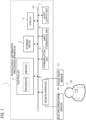
- FIG. 1 illustrates a hardware configuration diagram of a physiological information processing apparatus 1 according to the present embodiment.
- the physiological information processing apparatus 1 (hereinafter, simply referred to as the processing apparatus 1) includes a controller 2, a storage device 3, a display 4, a communication unit 5, an input operation unit 6, an audio output unit 7, and a sensor interface 8. These components provided in the processing apparatus 1 are communicably connected to each other via a bus 14.
- the processing apparatus 1 may be a medical instrument (for example, a patient monitor) that displays physiological information on a subject P, a personal computer, a workstation, a smartphone, a tablet, or a wearable device (for example, an AR glass) worn on a body (for example, an arm, a head) of a healthcare worker.
- a medical instrument for example, a patient monitor
- the subject P wears a pacemaker 16 that is an example of a CIED.
- the pacemaker 16 is implanted in the body of the subject P, and outputs a pacing pulse that applies electrical stimulation to the heart of the subject P.
- the timing at which the pacing pulse is output from the pacemaker 16 may overlap the output timing of a QRS complex in an electrocardiogram waveform indicating an electrical activity of the heart of the subject P.
- the QRS complex on which the pacing pulse is superimposed is generally referred to as a fusion beat or a pseudofusion beat.
- the pacing pulse adversely affects the QRS complex, and accordingly reliability of a diagnosis result of a cardiac function of the subject P based on a feature related to the QRS complex may decrease.
- the processing apparatus 1 does not store data related to the QRS complex present near the pacing pulse on a timeline when the output timing of the pacing pulse substantially overlaps the output timing of the QRS complex. That is, although the QRS complex present near the pacing pulse on the timeline is actually present on electrocardiogram data, the processing apparatus 1 does not detect the QRS complex or store data related to the QRS complex. On the other hand, the processing apparatus 1 according to the present embodiment has a function of determining, based on pulse wave data, whether the QRS complex not detected due to the presence of the pacing pulse is actually present. Details of the determination function will be described later.
- the controller 2 includes one or more memories and one or more procesors.
- the memory stores a computer readable command (program).
- the memory includes, for example, a read only memory (ROM) that stores various programs and the like, and a random access memory (RAM) having a plurality of work areas in which various programs and the like to be executed by the processor are stored.
- the processor includes, for example, at least one of a central processing unit (CPU), a micro-processing unit (MPU), and a graphics processing unit (GPU).
- the CPU may include a plurality of CPU cores.
- the GPU may include a plurality of GPU cores.
- the processor may load a designated program from various programs provided in the storage device 3 or the ROM onto the RAM and execute various processes in cooperation with the RAM
- the controller 2 executes the series of processes illustrated in FIGS. 3 to 5 . Details of the physiological information processing program will be described later.
- the storage device 3 is, for example, a storage device (storage) such as a hard disk drive (HDD), a solid state drive (SSD), or a flash memory, and stores programs and various data.
- the physiological information processing program may be provided in the storage device 3.
- physiological information data electrocardiogram data, pulse wave data, or the like
- electrocardiogram data obtained by an electrocardiogram sensor 10 may be stored in the storage device 3 via the sensor interface 8.
- the communication unit 5 connects the processing apparatus 1 to an in-hospital network.
- the communication unit 5 may include various wired connection terminals that communicate with a central monitor or a server provided in the in-hospital network.
- the communication unit 5 may further include a wireless communication module that performs wireless communication with the central monitor or the server.
- the communication unit 5 may include, for example, a wireless communication module corresponding to a medical telemeter system.
- the communication unit 5 may include a wireless communication module corresponding to a wireless communication standard such as Wi-Fi (registered trademark) or Bluetooth (registered trademark) and/or a wireless communication module corresponding to a mobile communication system using a SIM.
- the in-hospital network may be, for example, a local area network (LAN) or a wide area network
- the processing apparatus 1 may be connected to the Internet via the in-hospital network.
- the display 4 displays information (for example, an electrocardiogram waveform or a pulse wave) related to physiological information data of the subject P obtained in real time, and is, for example, a liquid crystal panel or an organic EL panel. Further, the display 4 displays, on a display screen, an alarm in accordance with a time interval between adjacent QRS complexes on a timeline.
- the input operation unit 6 is, for example, a touch panel overlapping the display 4, a mouse, and/or a keyboard.
- the input operation unit 6 receives an input operation by the healthcare worker and generates an operation signal corresponding to the input operation by the healthcare worker. After the operation signal generated by the input operation unit 6 is transmitted to the controller 2 via the bus 14, the controller 2 executes a predetermined operation in accordance with the operation signal.
- the audio output unit 7 includes one or more speakers, and outputs an audio alarm in accordance with the time interval between adjacent QRS complexes on the timeline.
- the sensor interface 8 is an interface that connects a vital sensor such as the electrocardiogram sensor 10 and a pulse wave sensor 12 to the processing apparatus 1.
- the sensor interface 8 may include an input terminal to which a physiological signal output from a vital sensor is input.
- the input terminal may be physically connected to a connector of the vital sensor.
- the electrocardiogram sensor 10 obtains an electrocardiogram signal indicating an electrical activity of the heart of the subject P, and includes a plurality of ECG electrodes attached to the subject P.
- the processing apparatus 1 generates electrocardiogram data based on an electrocardiogram signal output from the electrocardiogram sensor 10 and detects a pacing pulse.
- the pulse wave sensor 12 obtains a pulse wave signal indicating a pulse wave of the subject P.
- the pulse wave sensor 12 may include, for example, a light emitter (for example, an LED) that emits red light and/or infrared light, and a light detecting element (for example, a photodiode) that detects light that is emitted from the light emitter and that passes through the finger of the subject P.
- the processing apparatus 1 generates pulse wave data based on a pulse wave signal output from the pulse wave sensor 12. Further, the processing apparatus 1 may obtain information on arterial transcutaneous oxygen saturation (SpO2) and/or blood pressure of the subject P based on the generated pulse wave data.
- SpO2 arterial transcutaneous oxygen saturation
- the sensor interface 8 includes a pacing pulse detection circuit 82, an electrocardiogram detection circuit 83, a drive circuit 84, and a pulse wave detection circuit 85.
- the pacing pulse detection circuit 82 detects a pacing pulse based on a highfrequency component (frequency band of several kHz) of the electrocardiogram signal output from the electrocardiogram sensor 10.
- the pacing pulse detection circuit 82 includes, for example, at least a high-pass filter and a comparator.
- the electrocardiogram detection circuit 83 generates electrocardiogram data (digital data) based on a low-frequency component (frequency band of several Hz) of the electrocardiogram signal output from the electrocardiogram sensor 10.
- the electrocardiogram detection circuit 83 includes at least a differential amplifier circuit, a low-pass filter, and an AD converter.
- the drive circuit 84 generates a drive signal for driving the pulse wave sensor 12 and then supplies the drive signal to the pulse wave sensor 12.
- the pulse wave detection circuit 85 generates pulse wave data (digital data) based on the pulse wave signal output from the pulse wave sensor 12.
- the pulse wave detection circuit 85 includes at least an amplifier circuit, a filter circuit, and an AD converter.
- the sensor interface 8 generates the electrocardiogram data (digital data) based on the electrocardiogram signal (analog signal) output from the electrocardiogram sensor 10, and then transmits the electrocardiogram data to the controller 2.
- the sensor interface 8 generates the pulse wave data (digital data) based on the pulse wave signal (analog signal) output from the pulse wave sensor 12, and then transmits the pulse wave data to the controller 2.
- FIG. 3 is a flowchart illustrating a process of obtaining a feature related to the QRS complex based on electrocardiogram data.
- the controller 2 obtains electrocardiogram data from the electrocardiogram sensor 10 via the sensor interface 8.
- the controller 2 detects a QRS complex indicating excitation of the ventricle from the electrocardiogram data based on a predetermined detection algorithm. For example, an example of a plurality of QRS complexes is illustrated in an upper part of FIG. 6 .
- the controller 2 specifies a feature related to the QRS complex for each of the plurality of QRS complexes (step S3).
- the feature related to the QRS complex includes, for example, at least one of an interval between adjacent QRS complexes on a timeline (specifically, an RR interval indicating an interval between adjacent R waves), a time width of the QRS complex, an amplitude of the QRS complex, a maximum value/minimum value of the QRS complex, and an area of the QRS complex.
- the controller 2 stores the feature related to the QRS complex in the memory or the storage device 3 (step S4).
- the controller 2 may store a moving average value (for example, a moving average value of 16 beats) of the feature related to the QRS complex.
- FIG. 4 is a flowchart illustrating a process of obtaining a feature related to a pulse wave based on pulse wave data.
- the controller 2 obtains pulse wave data from the pulse wave sensor 12 via the sensor interface 8.
- the controller 2 detects a pulse wave from the pulse wave data based on a predetermined detection algorithm. For example, an example of a plurality of pulse waves is illustrated in a lower part of FIG. 6 .
- the controller 2 specifies a feature related to the pulse wave for each of the plurality of pulse waves (step S13).
- the feature related to the pulse wave includes, for example, at least one of an amplitude of the pulse wave, a time width of the pulse wave, a maximum value/minimum value of the pulse wave, contraction time of the pulse wave, and delay time of the pulse wave.
- the "contraction time of the pulse wave” is time from a time point corresponding to a rising point of the pulse wave to a time point corresponding to a peak point of the pulse wave.
- the "delay time of the pulse wave” corresponds to a time interval between a detection time point at which the pulse wave is detected and a detection time point at which the QRS complex associated with the pulse wave (particularly, the QRS complex appearing immediately before the pulse wave) is detected. More specifically, the “delay time of the pulse wave” may be a time interval between the time point corresponding to the rising point of the pulse wave and a time point corresponding to a rising point of the QRS complex appearing immediately before the pulse wave, or a time interval between the time point corresponding to the peak point of the pulse wave and a time point corresponding to the peak point of the QRS complex appearing immediately before the pulse wave.
- the controller 2 stores the feature related to the pulse wave in the memory or the storage device 3 (step S14). In this case, the controller 2 may store a moving average value (for example, a moving average value of 16 beats) of the feature related to the pulse wave.
- FIG. 5 is a flowchart illustrating the physiological information processing method according to the present embodiment.
- FIG. 6 is a diagram illustrating QRS complexes 22, 23 not detected due to the pacing pulse and pulse waves 32, 33 present within predetermined time from detection time points t1, t2 of the pacing pulse.
- the processing apparatus 1 does not detect the QRS complex present near the pacing pulse on a timeline. It is further assumed that the processing apparatus 1 executes an example of the process illustrated in FIG. 5 while executing the series of processes illustrated in FIG. 3 (that is, while obtaining the QRS complex from the electrocardiogram data).
- step S20 the controller 2 determines whether a time period ⁇ T in which the QRS complex is not detected is equal to or longer than a predetermined time width.
- the predetermined time width is, for example, a predetermined value between 200 milliseconds and 2 seconds.
- the controller 2 detects that the time period ⁇ T is equal to or longer than the predetermined time width (Yes in step S20)
- the controller 2 executes the processing of step S21.
- the controller 2 waits until the time period ⁇ T is equal to or longer than the predetermined time width.
- the QRS complexes 22, 23 overlap the pacing pulse on the timeline, the QRS complexes 22, 23 are not detected by the processing apparatus 1. That is, the time period ⁇ T in which the QRS complex is not detected is a time period from a time point corresponding to a peak point of a QRS complex 21 to a time point corresponding to a peak point of a QRS complex 24. In addition, it is assumed that the pacing pulse is detected at the time points t1, t2.
- step S21 the controller 2 determines whether a pacing pulse is detected in the time period ⁇ T. In particular, the controller 2 determines whether a pacing pulse is detected in the time period ⁇ T based on information output from the pacing pulse detection circuit 82. When a determination result of step S21 is Yes, the process proceeds to step S22. On the other hand, when the determination result of step S21 is No, the process proceeds to step S25. In this case, the controller 2 determines that the QRS complex is not present in the time period ⁇ T (step S25), and then executes the processing of step S26.
- step S22 the controller 2 determines, based on pulse wave data, whether a pulse wave is present within predetermined time from a detection time point at which a pacing pulse is detected.
- the predetermined time is, for example, 1 second.
- the controller 2 determines whether the pulse wave 32 is present within predetermined time from the detection time point t1, and determines whether the pulse wave 33 is present within predetermined time from the detection time point t2, based on the pulse wave data.
- step S23 the controller 2 determines whether reliability of the pulse wave present within the predetermined time is high.
- the controller 2 may determine the reliability of the pulse wave by comparing a feature of the pulse wave present within the predetermined time with a feature of a pulse wave stored in the memory.
- the feature of the pulse wave includes at least one of the amplitude of the pulse wave, the time width of the pulse wave, the maximum value/minimum value of the pulse wave, the contraction time of the pulse wave, and the delay time of the pulse wave.
- the controller 2 may determine that the reliability of the pulse wave 32 is high when a feature of the pulse wave 32 present within the predetermined time satisfies a part or all of the following conditions.
- the controller 2 may determine the reliability of the pulse wave by determining whether noise is superimposed on the pulse wave present within the predetermined time, in addition to the comparison between the feature of the pulse wave present within the predetermined time and the feature of the pulse wave stored in the memory. For example, when the reliability of the pulse wave 32 is high in a comparison result between the feature of the pulse wave 32 and the feature of the pulse wave stored in the memory and noise is superimposed on the pulse wave, the controller 2 may determine that the reliability of the pulse wave 32 is not high. When the reliability of the pulse wave 32 is high in the comparison result between the feature of the pulse wave 32 and the feature of the pulse wave stored in the memory and noise is not superimposed on the pulse wave 32, the controller 2 may determine that the reliability of the pulse wave 32 is high. In this way, the reliability of the pulse wave is determined in consideration of the noise superimposed on the pulse wave, and thus it is possible to more accurately determine the reliability of the pulse wave.
- step S23 determines that the QRS complex is actually present in the time period ⁇ T, and updates data related to the QRS complex.
- the controller 2 can determine that the two QRS complexes 22, 23 are actually present within the time period ⁇ T after determining that the reliability of the two pulse waves 32, 33 is high.
- the controller 2 may update, as the data related to the QRS complex, information related to the time interval between adjacent QRS complexes (in particular, information related to the RR interval).
- the controller 2 may store the detection time point t1 at which the pacing pulse is detected as a detection time point at which the QRS complex 22 is detected (in particular, the time point corresponding to the peak point of the QRS complex 22), and may store the detection time point t2 at which the pacing pulse is detected as a detection time point at which the QRS complex 23 is detected (in particular, the time point corresponding to the peak point of the QRS complex 23).
- step S26 the controller 2 determines whether to visually or audibly output an alarm indicating an abnormality of the cardiac function of the subject P to the outside based on the data related to the QRS complex.
- the controller 2 may determine whether to output an alarm to the outside in accordance with a comparison between the time interval between adjacent QRS complexes and a predetermined threshold value Tth.
- the predetermined threshold value Tth may be set within a range of 3 seconds to 5 seconds, or be a value N times (N > 1) the average value of the measured RR interval.
- the controller 2 may determine to output an alarm to the outside and then output the alarm to the outside through the audio output unit 7 and/or the display 4.
- the controller 2 determines not to output the alarm to the outside.
- the controller 2 may output a plurality of types of alarms to the outside according to the state of the cardiac function of the subject P (severity level of the cardiac function). In this case, the controller 2 may change the type of an alarm to be output to the outside according to the time interval between adjacent QRS complexes. For example, the controller 2 may output a first alarm to the outside when the time interval is between a first threshold value Tth1 and a second threshold value Tth2. When the time interval is larger than the second threshold value Tth2, the controller 2 may output a second alarm different from the first alarm to the outside.
- the time interval between adjacent QRS complexes exceeds the predetermined threshold value Tth.
- Tth since the time interval ⁇ T between the time point corresponding to the peak point of the QRS complex 21 and the time point corresponding to the peak point of the QRS complex 24 exceeds the predetermined threshold value Tth, an alarm is output from the processing apparatus.
- an alarm indicating an abnormality of the cardiac function of the subject P is erroneously output from the processing apparatus.
- the processing apparatus 1 that can more accurately determine the state of the cardiac function of the subject P wearing the pacemaker.
- the QRS complex is actually present in the time period ⁇ T according to the determination of a high reliability of the pulse wave present within predetermined time (for example, within 1 second) from the detection time point of the pacing pulse. In this way, it is possible to more reliably determine that the QRS complex is actually present within the time period ⁇ T, and it is possible to more accurately determine the state of the cardiac function of the subject P.
- step S23 the determination processing (step S23) related to the reliability of the pulse wave is executed, but the determination processing of step S23 is not necessarily executed.
- the controller 2 may determine that the QRS complex is actually present in the time period ⁇ T and update the data related to the QRS complex.
- a physiological information processing program may be pre-loaded into the storage device 3 or the ROM.
- the physiological information processing program may be stored in a computer-readable storage medium such as a magnetic disk (for example, a HDD or a floppy disk), an optical disk (for example, a CD-ROM, a DVD-ROM, or a Blu-ray (registered trademark) disk), a magneto-optical disk (for example, a MO), or a flash memory (for example, a SD card, a USB memory, or a SSD).
- the physiological information processing program stored in the storage medium may be loaded into the storage device 3.
- the program assembled in the storage device 3 may be loaded onto the RAM, and then the processor may execute the program loaded onto the RAM In this way, the physiological information processing method according to the present embodiment is executed by the processing apparatus 1.
- the physiological information processing program may be downloaded from a computer on a communication network via the communication unit 5.
- the downloaded program may be loaded into the storage device 3.
Landscapes
- Health & Medical Sciences (AREA)
- Life Sciences & Earth Sciences (AREA)
- Cardiology (AREA)
- Engineering & Computer Science (AREA)
- Public Health (AREA)
- Medical Informatics (AREA)
- Veterinary Medicine (AREA)
- Physics & Mathematics (AREA)
- General Health & Medical Sciences (AREA)
- Biophysics (AREA)
- Pathology (AREA)
- Biomedical Technology (AREA)
- Heart & Thoracic Surgery (AREA)
- Animal Behavior & Ethology (AREA)
- Molecular Biology (AREA)
- Surgery (AREA)
- Physiology (AREA)
- Signal Processing (AREA)
- Psychiatry (AREA)
- Computer Vision & Pattern Recognition (AREA)
- Artificial Intelligence (AREA)
- Vascular Medicine (AREA)
- Measurement And Recording Of Electrical Phenomena And Electrical Characteristics Of The Living Body (AREA)
- Measuring Pulse, Heart Rate, Blood Pressure Or Blood Flow (AREA)
Abstract
Description
- The presently disclosed subject matter relates to a physiological information processing apparatus and a physiological information processing method. The presently disclosed subject matter further relates to a program that causes a computer to execute the physiological information processing method.
- When an electrocardiogram waveform of a patient with a cardiovascular implantable electronic device (CIED) such as a pacemaker is measured, a pacing pulse output from the electronic device may be erroneously recognized as a QRS complex by a patient monitor. As a result, reliability of a diagnosis result of a cardiac function of the patient based on electrocardiogram data decreases.
- On the other hand, in consideration of a fact that the pacing pulse affects the QRS complex,
Patent Literature 1 discloses a processing method for preventing a patient monitor from detecting a QRS complex present near the time of a detected pacing pulse. - Patent Literature 1:
Japanese Patent No. 2635079 - When no QRS complex present near the time of pacing pulse is detected, a healthcare worker cannot accurately grasp an actual state of a cardiac function of a patient with a pacemaker or the like. In this regard, for example, even when the cardiac function of the patient is in a normal state, a time interval between adjacent QRS complexes becomes large when none of a plurality of QRS complexes is detected due to the presence of pacing pulses. As a result, it is assumed that an alarm indicating an abnormality of the cardiac function of the patient is erroneously output from the patient monitor. In this way, from the above viewpoint, there is room for consideration of a processing apparatus that can suitably prevent a situation in which the actually present QRS complex is not detected due to the pacing pulse.
- An object of the presently disclosed subject matter is to provide a physiological information processing apparatus and a physiological information processing method that can suitably prevent a situation in which an actually present QRS complex is not detected due to a pacing pulse.
- A physiological information processing apparatus according to a first aspect of the presently disclosed subject matter includes:
- one or more processors; and
- one or more memories configured to store a computer readable command.
- In a case where the computer readable command is executed by the processor, the physiological information processing apparatus:
- acquires electrocardiogram data of a subject;
- detects a QRS complex from the electrocardiogram data;
- acquires pulse wave data of the subject;
- detects a pacing pulse output from an apparatus worn by the subject;
- determines whether the pacing pulse is detected in a time period in which the QRS complex is not detected when the time period is equal to or longer than a predetermined time width;
- determines, based on the pulse wave data, whether a pulse wave is present within predetermined time from a detection time point at which the pacing pulse is detected; and
- determines, according to a determination that the pulse wave is present within the predetermined time, that the QRS complex is actually present in the time period.
- According to the above configuration, the physiological information processing apparatus determines whether the pacing pulse is present in the time period in which the QRS complex is not detected when the time period is equal to or longer than the predetermined time width. Further, the physiological information processing apparatus determines, according to the determination that the pulse wave related to the QRS complex is present within the predetermined time from the detection time point at which the pacing pulse is detected, that the QRS complex is actually present in the time period. In this way, it is possible to provide a physiological information processing apparatus that can suitably prevent a situation in which an actually present QRS complex is not detected due to a pacing pulse.
- A physiological information processing method executed by a computer according to a second aspect of the presently disclosed subject matter includes:
- acquiring electrocardiogram data of a subject;
- detecting a QRS complex from the electrocardiogram data;
- acquiring pulse wave data of the subject;
- detecting a pacing pulse output from an apparatus implanted in a body of the subject;
- determining whether the pacing pulse is detected in a time period in which the QRS complex is not detected when the time period is equal to or longer than a predetermined time width;
- determining, based on the pulse wave data, whether a pulse wave is present within predetermined time from a detection time point at which the pacing pulse is detected; and
- determining, according to a determination that the pulse wave is present within the predetermined time, that the QRS complex is actually present in the time period.
- There is provided a program that causes a computer to execute the physiological information processing method.
- According to the presently disclosed subject matter, it is possible to provide a physiological information processing apparatus and a physiological information processing method that can suitably prevent a situation in which an actually present QRS complex is not detected due to a pacing pulse.
-
-
FIG. 1 is a hardware configuration diagram illustrating a physiological information processing apparatus according to the presently disclosed subject matter (hereinafter, simply referred to as the present embodiment). -
FIG. 2 is a diagram illustrating an example of a configuration of a sensor interface. -
FIG. 3 is a flowchart illustrating a process of obtaining a feature related to a QRS complex from electrocardiogram data. -
FIG. 4 is a flowchart illustrating a process of obtaining a feature related to a pulse wave from pulse wave data. -
FIG. 5 is a flowchart illustrating a physiological information processing method according to the present embodiment. -
FIG. 6 is a diagram illustrating a QRS complex not detected due to a pacing pulse and a pulse wave present within predetermined time from a detection time point of the pacing pulse. - Hereinafter, an embodiment will be described with reference to the drawings. For convenience of description, description of elements having the same reference numerals as those already described in the description of the present embodiment will be omitted.
-
FIG. 1 illustrates a hardware configuration diagram of a physiologicalinformation processing apparatus 1 according to the present embodiment. As illustrated inFIG. 1 , the physiological information processing apparatus 1 (hereinafter, simply referred to as the processing apparatus 1) includes acontroller 2, astorage device 3, adisplay 4, acommunication unit 5, aninput operation unit 6, anaudio output unit 7, and asensor interface 8. These components provided in theprocessing apparatus 1 are communicably connected to each other via abus 14. - The
processing apparatus 1 may be a medical instrument (for example, a patient monitor) that displays physiological information on a subject P, a personal computer, a workstation, a smartphone, a tablet, or a wearable device (for example, an AR glass) worn on a body (for example, an arm, a head) of a healthcare worker. - The subject P wears a
pacemaker 16 that is an example of a CIED. Thepacemaker 16 is implanted in the body of the subject P, and outputs a pacing pulse that applies electrical stimulation to the heart of the subject P. The timing at which the pacing pulse is output from thepacemaker 16 may overlap the output timing of a QRS complex in an electrocardiogram waveform indicating an electrical activity of the heart of the subject P. The QRS complex on which the pacing pulse is superimposed is generally referred to as a fusion beat or a pseudofusion beat. In this case, the pacing pulse adversely affects the QRS complex, and accordingly reliability of a diagnosis result of a cardiac function of the subject P based on a feature related to the QRS complex may decrease. In this way, theprocessing apparatus 1 according to the present embodiment does not store data related to the QRS complex present near the pacing pulse on a timeline when the output timing of the pacing pulse substantially overlaps the output timing of the QRS complex. That is, although the QRS complex present near the pacing pulse on the timeline is actually present on electrocardiogram data, theprocessing apparatus 1 does not detect the QRS complex or store data related to the QRS complex. On the other hand, theprocessing apparatus 1 according to the present embodiment has a function of determining, based on pulse wave data, whether the QRS complex not detected due to the presence of the pacing pulse is actually present. Details of the determination function will be described later. - The
controller 2 includes one or more memories and one or more procesors. The memory stores a computer readable command (program). The memory includes, for example, a read only memory (ROM) that stores various programs and the like, and a random access memory (RAM) having a plurality of work areas in which various programs and the like to be executed by the processor are stored. The processor includes, for example, at least one of a central processing unit (CPU), a micro-processing unit (MPU), and a graphics processing unit (GPU). The CPU may include a plurality of CPU cores. The GPU may include a plurality of GPU cores. The processor may load a designated program from various programs provided in thestorage device 3 or the ROM onto the RAM and execute various processes in cooperation with the RAM In particular, when the processor loads a physiological information processing program for executing a series of processes illustrated inFIGS. 3 to 5 onto the RAM and executes the program in cooperation with the RAM, thecontroller 2 executes the series of processes illustrated inFIGS. 3 to 5 . Details of the physiological information processing program will be described later. - The
storage device 3 is, for example, a storage device (storage) such as a hard disk drive (HDD), a solid state drive (SSD), or a flash memory, and stores programs and various data. The physiological information processing program may be provided in thestorage device 3. Further, physiological information data (electrocardiogram data, pulse wave data, or the like) indicating physiological information on the subject P may be stored in thestorage device 3. For example, electrocardiogram data obtained by anelectrocardiogram sensor 10 may be stored in thestorage device 3 via thesensor interface 8. - The
communication unit 5 connects theprocessing apparatus 1 to an in-hospital network. Specifically, thecommunication unit 5 may include various wired connection terminals that communicate with a central monitor or a server provided in the in-hospital network. Thecommunication unit 5 may further include a wireless communication module that performs wireless communication with the central monitor or the server. Thecommunication unit 5 may include, for example, a wireless communication module corresponding to a medical telemeter system. Thecommunication unit 5 may include a wireless communication module corresponding to a wireless communication standard such as Wi-Fi (registered trademark) or Bluetooth (registered trademark) and/or a wireless communication module corresponding to a mobile communication system using a SIM. The in-hospital network may be, for example, a local area network (LAN) or a wide area network - (WAN). The
processing apparatus 1 may be connected to the Internet via the in-hospital network. - The
display 4 displays information (for example, an electrocardiogram waveform or a pulse wave) related to physiological information data of the subject P obtained in real time, and is, for example, a liquid crystal panel or an organic EL panel. Further, thedisplay 4 displays, on a display screen, an alarm in accordance with a time interval between adjacent QRS complexes on a timeline. Theinput operation unit 6 is, for example, a touch panel overlapping thedisplay 4, a mouse, and/or a keyboard. Theinput operation unit 6 receives an input operation by the healthcare worker and generates an operation signal corresponding to the input operation by the healthcare worker. After the operation signal generated by theinput operation unit 6 is transmitted to thecontroller 2 via thebus 14, thecontroller 2 executes a predetermined operation in accordance with the operation signal. Theaudio output unit 7 includes one or more speakers, and outputs an audio alarm in accordance with the time interval between adjacent QRS complexes on the timeline. - The
sensor interface 8 is an interface that connects a vital sensor such as theelectrocardiogram sensor 10 and apulse wave sensor 12 to theprocessing apparatus 1. Thesensor interface 8 may include an input terminal to which a physiological signal output from a vital sensor is input. The input terminal may be physically connected to a connector of the vital sensor. Theelectrocardiogram sensor 10 obtains an electrocardiogram signal indicating an electrical activity of the heart of the subject P, and includes a plurality of ECG electrodes attached to the subject P. Theprocessing apparatus 1 generates electrocardiogram data based on an electrocardiogram signal output from theelectrocardiogram sensor 10 and detects a pacing pulse. Thepulse wave sensor 12 obtains a pulse wave signal indicating a pulse wave of the subject P. Thepulse wave sensor 12 may include, for example, a light emitter (for example, an LED) that emits red light and/or infrared light, and a light detecting element (for example, a photodiode) that detects light that is emitted from the light emitter and that passes through the finger of the subject P. Theprocessing apparatus 1 generates pulse wave data based on a pulse wave signal output from thepulse wave sensor 12. Further, theprocessing apparatus 1 may obtain information on arterial transcutaneous oxygen saturation (SpO2) and/or blood pressure of the subject P based on the generated pulse wave data. - Next, the
sensor interface 8 will be described in detail with reference toFIG. 2 . As illustrated inFIG. 2 , thesensor interface 8 includes a pacingpulse detection circuit 82, anelectrocardiogram detection circuit 83, adrive circuit 84, and a pulsewave detection circuit 85. - The pacing
pulse detection circuit 82 detects a pacing pulse based on a highfrequency component (frequency band of several kHz) of the electrocardiogram signal output from theelectrocardiogram sensor 10. The pacingpulse detection circuit 82 includes, for example, at least a high-pass filter and a comparator. Theelectrocardiogram detection circuit 83 generates electrocardiogram data (digital data) based on a low-frequency component (frequency band of several Hz) of the electrocardiogram signal output from theelectrocardiogram sensor 10. Theelectrocardiogram detection circuit 83 includes at least a differential amplifier circuit, a low-pass filter, and an AD converter. Thedrive circuit 84 generates a drive signal for driving thepulse wave sensor 12 and then supplies the drive signal to thepulse wave sensor 12. The pulsewave detection circuit 85 generates pulse wave data (digital data) based on the pulse wave signal output from thepulse wave sensor 12. The pulsewave detection circuit 85 includes at least an amplifier circuit, a filter circuit, and an AD converter. - In this way, the
sensor interface 8 generates the electrocardiogram data (digital data) based on the electrocardiogram signal (analog signal) output from theelectrocardiogram sensor 10, and then transmits the electrocardiogram data to thecontroller 2. Thesensor interface 8 generates the pulse wave data (digital data) based on the pulse wave signal (analog signal) output from thepulse wave sensor 12, and then transmits the pulse wave data to thecontroller 2. - Next, a process of obtaining a feature related to the QRS complex based on electrocardiogram data will be described below with reference to
FIG. 3. FIG. 3 is a flowchart illustrating a process of obtaining a feature related to the QRS complex based on electrocardiogram data. As illustrated inFIG. 3 , in step S1, thecontroller 2 obtains electrocardiogram data from theelectrocardiogram sensor 10 via thesensor interface 8. In step S2, thecontroller 2 detects a QRS complex indicating excitation of the ventricle from the electrocardiogram data based on a predetermined detection algorithm. For example, an example of a plurality of QRS complexes is illustrated in an upper part ofFIG. 6 . - Next, the
controller 2 specifies a feature related to the QRS complex for each of the plurality of QRS complexes (step S3). The feature related to the QRS complex includes, for example, at least one of an interval between adjacent QRS complexes on a timeline (specifically, an RR interval indicating an interval between adjacent R waves), a time width of the QRS complex, an amplitude of the QRS complex, a maximum value/minimum value of the QRS complex, and an area of the QRS complex. Thereafter, thecontroller 2 stores the feature related to the QRS complex in the memory or the storage device 3 (step S4). In this case, thecontroller 2 may store a moving average value (for example, a moving average value of 16 beats) of the feature related to the QRS complex. - Further, a process of obtaining a feature related to a pulse wave based on pulse wave data will be described below with reference to
FIG. 4. FIG. 4 is a flowchart illustrating a process of obtaining a feature related to a pulse wave based on pulse wave data. As illustrated inFIG. 4 , in step S11, thecontroller 2 obtains pulse wave data from thepulse wave sensor 12 via thesensor interface 8. In step S12, thecontroller 2 detects a pulse wave from the pulse wave data based on a predetermined detection algorithm. For example, an example of a plurality of pulse waves is illustrated in a lower part ofFIG. 6 . - Next, the
controller 2 specifies a feature related to the pulse wave for each of the plurality of pulse waves (step S13). The feature related to the pulse wave includes, for example, at least one of an amplitude of the pulse wave, a time width of the pulse wave, a maximum value/minimum value of the pulse wave, contraction time of the pulse wave, and delay time of the pulse wave. The "contraction time of the pulse wave" is time from a time point corresponding to a rising point of the pulse wave to a time point corresponding to a peak point of the pulse wave. The "delay time of the pulse wave" corresponds to a time interval between a detection time point at which the pulse wave is detected and a detection time point at which the QRS complex associated with the pulse wave (particularly, the QRS complex appearing immediately before the pulse wave) is detected. More specifically, the "delay time of the pulse wave" may be a time interval between the time point corresponding to the rising point of the pulse wave and a time point corresponding to a rising point of the QRS complex appearing immediately before the pulse wave, or a time interval between the time point corresponding to the peak point of the pulse wave and a time point corresponding to the peak point of the QRS complex appearing immediately before the pulse wave. Thereafter, thecontroller 2 stores the feature related to the pulse wave in the memory or the storage device 3 (step S14). In this case, thecontroller 2 may store a moving average value (for example, a moving average value of 16 beats) of the feature related to the pulse wave. - Next, a physiological information processing method according to the present embodiment will be described below with reference to
FIGS. 5 and6 .FIG. 5 is a flowchart illustrating the physiological information processing method according to the present embodiment.FIG. 6 is a diagram illustratingQRS complexes processing apparatus 1 according to the present embodiment does not detect the QRS complex present near the pacing pulse on a timeline. It is further assumed that theprocessing apparatus 1 executes an example of the process illustrated inFIG. 5 while executing the series of processes illustrated inFIG. 3 (that is, while obtaining the QRS complex from the electrocardiogram data). - As illustrated in
FIG. 5 , in step S20, thecontroller 2 determines whether a time period ΔT in which the QRS complex is not detected is equal to or longer than a predetermined time width. Here, the predetermined time width is, for example, a predetermined value between 200 milliseconds and 2 seconds. When thecontroller 2 detects that the time period ΔT is equal to or longer than the predetermined time width (Yes in step S20), thecontroller 2 executes the processing of step S21. On the other hand, when the determination processing of step S20 is No, thecontroller 2 waits until the time period ΔT is equal to or longer than the predetermined time width. - In the example illustrated in
FIG. 6 , since theQRS complexes QRS complexes processing apparatus 1. That is, the time period ΔT in which the QRS complex is not detected is a time period from a time point corresponding to a peak point of aQRS complex 21 to a time point corresponding to a peak point of aQRS complex 24. In addition, it is assumed that the pacing pulse is detected at the time points t1, t2. - Next, in step S21, the
controller 2 determines whether a pacing pulse is detected in the time period ΔT. In particular, thecontroller 2 determines whether a pacing pulse is detected in the time period ΔT based on information output from the pacingpulse detection circuit 82. When a determination result of step S21 is Yes, the process proceeds to step S22. On the other hand, when the determination result of step S21 is No, the process proceeds to step S25. In this case, thecontroller 2 determines that the QRS complex is not present in the time period ΔT (step S25), and then executes the processing of step S26. - In step S22, the
controller 2 determines, based on pulse wave data, whether a pulse wave is present within predetermined time from a detection time point at which a pacing pulse is detected. Here, the predetermined time is, for example, 1 second. In the example illustrated inFIG. 6 , thecontroller 2 determines whether thepulse wave 32 is present within predetermined time from the detection time point t1, and determines whether thepulse wave 33 is present within predetermined time from the detection time point t2, based on the pulse wave data. When a determination result of step S22 is Yes, the process proceeds to step S23, and when the determination result of step S22 is No, the process proceeds to step S25. - In step S23, the
controller 2 determines whether reliability of the pulse wave present within the predetermined time is high. In particular, thecontroller 2 may determine the reliability of the pulse wave by comparing a feature of the pulse wave present within the predetermined time with a feature of a pulse wave stored in the memory. As described above, the feature of the pulse wave includes at least one of the amplitude of the pulse wave, the time width of the pulse wave, the maximum value/minimum value of the pulse wave, the contraction time of the pulse wave, and the delay time of the pulse wave. - For example, the
controller 2 may determine that the reliability of thepulse wave 32 is high when a feature of thepulse wave 32 present within the predetermined time satisfies a part or all of the following conditions. - The amplitude of the
pulse wave 32 is 0.25 to less than 3 times an average amplitude of the pulse wave stored in the memory. - The delay time of the
pulse wave 32 from the detection time point t1 of the pacing pulse to the detection time point of thepulse wave 32 is within ± 80 ms of average delay time of the pulse wave stored in the memory. - The delay time of the
pulse wave 32 from the detection time point t1 of the pacing pulse to the detection time point of thepulse wave 32 is within ± 80 ms of the delay time of thepulse wave 31 adjacent to thepulse wave 32. - The contraction time of the
pulse wave 32 is not longer than average contraction time of the pulse wave stored in the memory by 120 ms or more. - The
controller 2 may determine the reliability of the pulse wave by determining whether noise is superimposed on the pulse wave present within the predetermined time, in addition to the comparison between the feature of the pulse wave present within the predetermined time and the feature of the pulse wave stored in the memory. For example, when the reliability of thepulse wave 32 is high in a comparison result between the feature of thepulse wave 32 and the feature of the pulse wave stored in the memory and noise is superimposed on the pulse wave, thecontroller 2 may determine that the reliability of thepulse wave 32 is not high. When the reliability of thepulse wave 32 is high in the comparison result between the feature of thepulse wave 32 and the feature of the pulse wave stored in the memory and noise is not superimposed on thepulse wave 32, thecontroller 2 may determine that the reliability of thepulse wave 32 is high. In this way, the reliability of the pulse wave is determined in consideration of the noise superimposed on the pulse wave, and thus it is possible to more accurately determine the reliability of the pulse wave. - When a determination result of step S23 is Yes, the process proceeds to step S24, and when the determination result of step S23 is No, the process proceeds to step S25. Next, in step S24, the
controller 2 determines that the QRS complex is actually present in the time period ΔT, and updates data related to the QRS complex. In the example illustrated inFIG. 6 , thecontroller 2 can determine that the twoQRS complexes pulse waves - Further, the
controller 2 may update, as the data related to the QRS complex, information related to the time interval between adjacent QRS complexes (in particular, information related to the RR interval). In this regard, thecontroller 2 may store the detection time point t1 at which the pacing pulse is detected as a detection time point at which theQRS complex 22 is detected (in particular, the time point corresponding to the peak point of the QRS complex 22), and may store the detection time point t2 at which the pacing pulse is detected as a detection time point at which theQRS complex 23 is detected (in particular, the time point corresponding to the peak point of the QRS complex 23). - Next, in step S26, the
controller 2 determines whether to visually or audibly output an alarm indicating an abnormality of the cardiac function of the subject P to the outside based on the data related to the QRS complex. In particular, thecontroller 2 may determine whether to output an alarm to the outside in accordance with a comparison between the time interval between adjacent QRS complexes and a predetermined threshold value Tth. Here, the predetermined threshold value Tth may be set within a range of 3 seconds to 5 seconds, or be a value N times (N > 1) the average value of the measured RR interval. For example, when the time interval (RR interval) between adjacent QRS complexes is equal to or greater than the predetermined threshold value Tth, thecontroller 2 may determine to output an alarm to the outside and then output the alarm to the outside through theaudio output unit 7 and/or thedisplay 4. On the other hand, when the time interval between the adjacent QRS complexes is smaller than the predetermined threshold value Tth, thecontroller 2 determines not to output the alarm to the outside. - The
controller 2 may output a plurality of types of alarms to the outside according to the state of the cardiac function of the subject P (severity level of the cardiac function). In this case, thecontroller 2 may change the type of an alarm to be output to the outside according to the time interval between adjacent QRS complexes. For example, thecontroller 2 may output a first alarm to the outside when the time interval is between a first threshold value Tth1 and a second threshold value Tth2. When the time interval is larger than the second threshold value Tth2, thecontroller 2 may output a second alarm different from the first alarm to the outside. - In the example illustrated in
FIG. 6 , since it is determined that theQRS complexes processing apparatus 1. In this way, when the cardiac function of the subject P is normal, it is possible to suitably prevent a situation in which an alarm indicating an abnormality of the cardiac function of the subject P is erroneously output from theprocessing apparatus 1. On the other hand, in a processing apparatus in the related art, since it is not determined whether theQRS complexes QRS complex 21 and the time point corresponding to the peak point of theQRS complex 24 exceeds the predetermined threshold value Tth, an alarm is output from the processing apparatus. As a result, although the cardiac function of the subject P is normal, an alarm indicating an abnormality of the cardiac function of the subject P is erroneously output from the processing apparatus. - As described above, according to the present embodiment, it is possible to suitably prevent a situation in which the actually present QRS complex is not detected due to the pacing pulse. Furthermore, when the cardiac function of the subject P wearing the
pacemaker 16 is normal, it is possible to suitably prevent a situation in which an alarm indicating an abnormality of the cardiac function of the subject P is erroneously output. Therefore, it is possible to provide theprocessing apparatus 1 that can more accurately determine the state of the cardiac function of the subject P wearing the pacemaker. - According to the present embodiment, it is determined that the QRS complex is actually present in the time period ΔT according to the determination of a high reliability of the pulse wave present within predetermined time (for example, within 1 second) from the detection time point of the pacing pulse. In this way, it is possible to more reliably determine that the QRS complex is actually present within the time period ΔT, and it is possible to more accurately determine the state of the cardiac function of the subject P.
- In the description of the present embodiment, the determination processing (step S23) related to the reliability of the pulse wave is executed, but the determination processing of step S23 is not necessarily executed. In this case, after determining in step S22 that the pulse wave is present within predetermined time from the detection time point at which the pacing pulse is detected, the
controller 2 may determine that the QRS complex is actually present in the time period ΔT and update the data related to the QRS complex. - In order to implement the
processing apparatus 1 according to the present embodiment by software, a physiological information processing program may be pre-loaded into thestorage device 3 or the ROM. Alternatively, the physiological information processing program may be stored in a computer-readable storage medium such as a magnetic disk (for example, a HDD or a floppy disk), an optical disk (for example, a CD-ROM, a DVD-ROM, or a Blu-ray (registered trademark) disk), a magneto-optical disk (for example, a MO), or a flash memory (for example, a SD card, a USB memory, or a SSD). In this case, the physiological information processing program stored in the storage medium may be loaded into thestorage device 3. Further, the program assembled in thestorage device 3 may be loaded onto the RAM, and then the processor may execute the program loaded onto the RAM In this way, the physiological information processing method according to the present embodiment is executed by theprocessing apparatus 1. - The physiological information processing program may be downloaded from a computer on a communication network via the
communication unit 5. In this case, same or similarly, the downloaded program may be loaded into thestorage device 3. - Although the embodiment of the presently disclosed subject matter is described above, the technical scope of the presently disclosed subject matter should not be construed as being limited to the description of the embodiment. It is understood by those skilled in the art that the present embodiment is an example and various modifications can be made within the scope of the inventions described in the claims. The technical scope of the presently disclosed subject matter should be determined based on the scope of the inventions described in the claims and the scope of equivalents thereof.
Claims (13)
- A physiological information processing apparatus comprising:one or more processors; andone or more memories configured to store a computer readable command,wherein in a case where the computer readable command is executed by the processor, the physiological information processing apparatus is configured to:acquire electrocardiogram data of a subject;detect a QRS complex from the electrocardiogram data;acquire pulse wave data of the subject;detect a pacing pulse output from an apparatus worn by the subject;determine whether the pacing pulse is detected in a time period in which the QRS complex is not detected when the time period is equal to or longer than a predetermined time width;determine, based on the pulse wave data, whether a pulse wave is present within predetermined time from a detection time point at which the pacing pulse is detected; anddetermine, according to a determination that the pulse wave is present within the predetermined time, that the QRS complex is actually present in the time period.
- The physiological information processing apparatus according to claim 1,wherein the physiological information processing apparatus is configured to:
update data related to the QRS complex according to the determination that the pulse wave is present within the predetermined time; anddetermine whether to audibly or visually output an alarm indicating an abnormality of a cardiac function of the subject to outside based on the data related to the QRS complex. - The physiological information processing apparatus according to claim 2,wherein the data related to the QRS complex includes information related to a time interval between adjacent QRS complexes on a timeline, andwherein the physiological information processing apparatus is configured to determine whether to audibly or visually output the alarm to the outside in accordance with a comparison between the time interval and a predetermined threshold value.
- The physiological information processing apparatus according to any one of claims 1 to 3,
wherein the physiological information processing apparatus is configured to:determine reliability of the pulse wave when the pulse wave is determined to be present within the predetermined time; anddetermine that the QRS complex is actually present in the time period according to a determination that the reliability of the pulse wave is high. - The physiological information processing apparatus according to claim 4,
wherein the physiological information processing apparatus is configured to determine the reliability of the pulse wave by comparing a feature of the pulse wave present within the predetermined time with a feature of a pulse wave stored in the memory. - The physiological information processing apparatus according to claim 5,
wherein the physiological information processing apparatus is configured to determine the reliability of the pulse wave by comparing the feature of the pulse wave present within the predetermined time with the feature of the pulse wave stored in the memory, and by determining whether noise is superimposed on the pulse wave present within the predetermined time. - The physiological information processing apparatus according to claim 5 or 6, wherein the feature of the pulse wave includes at least one of:a feature related to an amplitude of the pulse wave;a feature related to contraction time of the pulse wave; anda feature related to delay time of the pulse wave corresponding to a time interval between a detection time point at which the pulse wave is detected and a detection time point at which the QRS complex associated with the pulse wave or the pacing pulse is detected.
- The physiological information processing apparatus according to claim 2 or 3,
wherein the physiological information processing apparatus is configured to update, according to the determination that the pulse wave is present within the predetermined time, the data related to the QRS complex by storing a detection time point at which the pacing pulse is detected as a detection time point at which the QRS complex is detected. - A physiological information processing method executed by a computer, the method comprising:acquiring electrocardiogram data of a subject;detecting a QRS complex from the electrocardiogram data;acquiring pulse wave data of the subject;detecting a pacing pulse output from an apparatus implanted in a body of the subject;determining whether the pacing pulse is detected in a time period in which the QRS complex is not detected when the time period is equal to or longer than a predetermined time width;determining, based on the pulse wave data, whether a pulse wave is present within predetermined time from a detection time point at which the pacing pulse is detected; anddetermining, according to a determination that the pulse wave is present within the predetermined time, that the QRS complex is actually present in the time period.
- The physiological information processing method according to claim 9, further comprising:updating data related to the QRS complex according to the determination that the pulse wave is present within the predetermined time; anddetermining whether to audibly or visually output an alarm indicating an abnormality of a cardiac function of the subject to outside based on the data related to the QRS complex.
- The physiological information processing method according to claim 10,wherein the data related to the QRS complex includes information related to a time interval between adjacent QRS complexes on a timeline, andwherein the method further includes determining whether to audibly or visually output the alarm to the outside in accordance with a comparison between the time interval and a predetermined threshold value.
- The physiological information processing method according to any one of claims 9 to 11, further comprising:determining reliability of the pulse wave when the pulse wave is determined to be present within the predetermined time, andwherein the method further includes determining that the QRS complex is actually present in the time period according to a determination that the reliability of the pulse wave is high.
- A program that causes a computer to execute the physiological information processing method according to any one of claims 9 to 12.
Applications Claiming Priority (1)
| Application Number | Priority Date | Filing Date | Title |
|---|---|---|---|
| JP2021154160A JP7661190B2 (en) | 2021-09-22 | 2021-09-22 | Biological information processing device, biological information processing method, and program |
Publications (1)
| Publication Number | Publication Date |
|---|---|
| EP4154807A1 true EP4154807A1 (en) | 2023-03-29 |
Family
ID=83688990
Family Applications (1)
| Application Number | Title | Priority Date | Filing Date |
|---|---|---|---|
| EP22195854.9A Pending EP4154807A1 (en) | 2021-09-22 | 2022-09-15 | Physiological information processing apparatus, physiological information processing method and program |
Country Status (3)
| Country | Link |
|---|---|
| US (1) | US20230093107A1 (en) |
| EP (1) | EP4154807A1 (en) |
| JP (1) | JP7661190B2 (en) |
Citations (3)
| Publication number | Priority date | Publication date | Assignee | Title |
|---|---|---|---|---|
| EP0424607A2 (en) * | 1989-10-24 | 1991-05-02 | Hewlett-Packard Company | Method for discriminating pace pulse tails |
| JP2635079B2 (en) | 1987-02-26 | 1997-07-30 | ヒューレット・パッカード・カンパニー | Method of removing pace pulse signal from ECG wave signal and apparatus for removing pace pulse signal from ECG wave signal |
| US20040116969A1 (en) * | 2002-08-26 | 2004-06-17 | Owen James M. | Pulse detection using patient physiological signals |
Family Cites Families (3)
| Publication number | Priority date | Publication date | Assignee | Title |
|---|---|---|---|---|
| JP2001190696A (en) | 2000-01-07 | 2001-07-17 | Seiko Instruments Inc | Portable information processing apparatus, information processing method, and computer-readable recording medium storing a program for causing a computer to execute the method |
| US9427594B1 (en) | 2015-05-26 | 2016-08-30 | Pacesetter, Inc. | Method and system for tracking events of interest between leadless and subcutaneous implantable cardioverter devices |
| GB201804933D0 (en) | 2018-03-27 | 2018-05-09 | Asgard Medical Innovations As | Method to analyze cardiac rhythms using beat-to-beat display plots |
-
2021
- 2021-09-22 JP JP2021154160A patent/JP7661190B2/en active Active
-
2022
- 2022-09-12 US US17/931,179 patent/US20230093107A1/en active Pending
- 2022-09-15 EP EP22195854.9A patent/EP4154807A1/en active Pending
Patent Citations (3)
| Publication number | Priority date | Publication date | Assignee | Title |
|---|---|---|---|---|
| JP2635079B2 (en) | 1987-02-26 | 1997-07-30 | ヒューレット・パッカード・カンパニー | Method of removing pace pulse signal from ECG wave signal and apparatus for removing pace pulse signal from ECG wave signal |
| EP0424607A2 (en) * | 1989-10-24 | 1991-05-02 | Hewlett-Packard Company | Method for discriminating pace pulse tails |
| US20040116969A1 (en) * | 2002-08-26 | 2004-06-17 | Owen James M. | Pulse detection using patient physiological signals |
Non-Patent Citations (1)
| Title |
|---|
| VESSELA KRASTEVA ET AL: "Real-time arrhythmia detection with supplementary ECG quality and pulse wave monitoring for the reduction of false alarms in ICUs", PHYSIOLOGICAL MEASUREMENT, INSTITUTE OF PHYSICS PUBLISHING, BRISTOL, GB, vol. 37, no. 8, 25 July 2016 (2016-07-25), pages 1273 - 1297, XP020307063, ISSN: 0967-3334, [retrieved on 20160725], DOI: 10.1088/0967-3334/37/8/1273 * |
Also Published As
| Publication number | Publication date |
|---|---|
| JP7661190B2 (en) | 2025-04-14 |
| JP2023045629A (en) | 2023-04-03 |
| US20230093107A1 (en) | 2023-03-23 |
Similar Documents
| Publication | Publication Date | Title |
|---|---|---|
| US20230329624A1 (en) | Visualization of arrhythmia detection by machine learning | |
| JP6918038B2 (en) | Mismatch monitoring | |
| KR102853899B1 (en) | Arrhythmia detection using feature description and machine learning | |
| US8554314B2 (en) | Device and method to detect the severity of ischemia and heart attack risk | |
| JP4734260B2 (en) | Distributed cardiac activity monitoring with selective filtering | |
| US10835129B2 (en) | System to diagnose and manage orthostatic intolerance | |
| JP2022531300A (en) | Power-reduced machine learning system for arrhythmia detection | |
| EP3020330B1 (en) | Apparatus for automated detection of pulse arrhythmia | |
| CN110621224B (en) | System and method for determining atrial fibrillation and pulse pressure variability | |
| US20190070419A1 (en) | Patient Monitoring Systems and Methods that Detect Interference with Pacemaker | |
| US20100010361A1 (en) | System and Method for Improved Ischemia and Acute Myocardial Infarction Detection | |
| JP6461696B2 (en) | Portable medical device, program, and biological information display method | |
| US9421382B2 (en) | Method and apparatus for monitoring of patient medication compliance | |
| US20230093107A1 (en) | Physiological information processing apparatus and physiological information processing method | |
| WO2020118154A1 (en) | Systems and methods for detecting arrhythmias | |
| US20210259617A1 (en) | Physiological information processing apparatus, physiological information processing methdo and storage medium | |
| WO2017170177A1 (en) | Electrocardiogram recording device and electrocardiogram analysis method | |
| CN114680857B (en) | Parameter determination method, parameter determination device, storage medium and electronic equipment | |
| EP3282939B1 (en) | Alignment of a detachable monitoring device | |
| EP4258983B1 (en) | Cardiopulmonary resuscitation decision support | |
| US20200323457A1 (en) | Heartbeat analyzer | |
| EP4011287A1 (en) | Cardiopulmonary resuscitation decision support | |
| US20150165214A1 (en) | Method and apparatus for monitoring of patient medication compliance |
Legal Events
| Date | Code | Title | Description |
|---|---|---|---|
| PUAI | Public reference made under article 153(3) epc to a published international application that has entered the european phase |
Free format text: ORIGINAL CODE: 0009012 |
|
| STAA | Information on the status of an ep patent application or granted ep patent |
Free format text: STATUS: THE APPLICATION HAS BEEN PUBLISHED |
|
| AK | Designated contracting states |
Kind code of ref document: A1 Designated state(s): AL AT BE BG CH CY CZ DE DK EE ES FI FR GB GR HR HU IE IS IT LI LT LU LV MC MK MT NL NO PL PT RO RS SE SI SK SM TR |
|
| STAA | Information on the status of an ep patent application or granted ep patent |
Free format text: STATUS: REQUEST FOR EXAMINATION WAS MADE |
|
| 17P | Request for examination filed |
Effective date: 20230919 |
|
| RBV | Designated contracting states (corrected) |
Designated state(s): AL AT BE BG CH CY CZ DE DK EE ES FI FR GB GR HR HU IE IS IT LI LT LU LV MC MK MT NL NO PL PT RO RS SE SI SK SM TR |
|
| STAA | Information on the status of an ep patent application or granted ep patent |
Free format text: STATUS: EXAMINATION IS IN PROGRESS |
|
| 17Q | First examination report despatched |
Effective date: 20250723 |
|
| GRAP | Despatch of communication of intention to grant a patent |
Free format text: ORIGINAL CODE: EPIDOSNIGR1 |
|
| STAA | Information on the status of an ep patent application or granted ep patent |
Free format text: STATUS: GRANT OF PATENT IS INTENDED |
|
| INTG | Intention to grant announced |
Effective date: 20260310 |
|
| RIC1 | Information provided on ipc code assigned before grant |
Ipc: A61B 5/024 20060101AFI20260302BHEP Ipc: A61B 5/366 20210101ALI20260302BHEP Ipc: A61B 5/00 20060101ALI20260302BHEP Ipc: A61N 1/362 20060101ALN20260302BHEP Ipc: A61N 1/37 20060101ALN20260302BHEP |