EP4154801A1 - Sensor device - Google Patents
Sensor device Download PDFInfo
- Publication number
- EP4154801A1 EP4154801A1 EP22195583.4A EP22195583A EP4154801A1 EP 4154801 A1 EP4154801 A1 EP 4154801A1 EP 22195583 A EP22195583 A EP 22195583A EP 4154801 A1 EP4154801 A1 EP 4154801A1
- Authority
- EP
- European Patent Office
- Prior art keywords
- main body
- body portion
- sensor device
- unit
- user
- Prior art date
- Legal status (The legal status is an assumption and is not a legal conclusion. Google has not performed a legal analysis and makes no representation as to the accuracy of the status listed.)
- Granted
Links
Images



Classifications
-
- A—HUMAN NECESSITIES
- A61—MEDICAL OR VETERINARY SCIENCE; HYGIENE
- A61B—DIAGNOSIS; SURGERY; IDENTIFICATION
- A61B5/00—Measuring for diagnostic purposes; Identification of persons
- A61B5/02—Detecting, measuring or recording for evaluating the cardiovascular system, e.g. pulse, heart rate, blood pressure or blood flow
- A61B5/024—Measuring pulse rate or heart rate
- A61B5/02438—Measuring pulse rate or heart rate with portable devices, e.g. worn by the patient
-
- A—HUMAN NECESSITIES
- A61—MEDICAL OR VETERINARY SCIENCE; HYGIENE
- A61B—DIAGNOSIS; SURGERY; IDENTIFICATION
- A61B5/00—Measuring for diagnostic purposes; Identification of persons
- A61B5/0002—Remote monitoring of patients using telemetry, e.g. transmission of vital signals via a communication network
- A61B5/0015—Remote monitoring of patients using telemetry, e.g. transmission of vital signals via a communication network characterised by features of the telemetry system
-
- A—HUMAN NECESSITIES
- A61—MEDICAL OR VETERINARY SCIENCE; HYGIENE
- A61B—DIAGNOSIS; SURGERY; IDENTIFICATION
- A61B5/00—Measuring for diagnostic purposes; Identification of persons
- A61B5/103—Measuring devices for testing the shape, pattern, colour, size or movement of the body or parts thereof, for diagnostic purposes
- A61B5/11—Measuring movement of the entire body or parts thereof, e.g. head or hand tremor or mobility of a limb
-
- A—HUMAN NECESSITIES
- A61—MEDICAL OR VETERINARY SCIENCE; HYGIENE
- A61B—DIAGNOSIS; SURGERY; IDENTIFICATION
- A61B5/00—Measuring for diagnostic purposes; Identification of persons
- A61B5/68—Arrangements of detecting, measuring or recording means, e.g. sensors, in relation to patient
- A61B5/6801—Arrangements of detecting, measuring or recording means, e.g. sensors, in relation to patient specially adapted to be attached to or worn on the body surface
- A61B5/6813—Specially adapted to be attached to a specific body part
- A61B5/6823—Trunk, e.g., chest, back, abdomen, hip
-
- A—HUMAN NECESSITIES
- A61—MEDICAL OR VETERINARY SCIENCE; HYGIENE
- A61B—DIAGNOSIS; SURGERY; IDENTIFICATION
- A61B5/00—Measuring for diagnostic purposes; Identification of persons
- A61B5/68—Arrangements of detecting, measuring or recording means, e.g. sensors, in relation to patient
- A61B5/6801—Arrangements of detecting, measuring or recording means, e.g. sensors, in relation to patient specially adapted to be attached to or worn on the body surface
- A61B5/683—Means for maintaining contact with the body
- A61B5/6838—Clamps or clips
-
- A—HUMAN NECESSITIES
- A61—MEDICAL OR VETERINARY SCIENCE; HYGIENE
- A61B—DIAGNOSIS; SURGERY; IDENTIFICATION
- A61B5/00—Measuring for diagnostic purposes; Identification of persons
- A61B5/103—Measuring devices for testing the shape, pattern, colour, size or movement of the body or parts thereof, for diagnostic purposes
- A61B5/11—Measuring movement of the entire body or parts thereof, e.g. head or hand tremor or mobility of a limb
- A61B5/1116—Determining posture transitions
-
- A—HUMAN NECESSITIES
- A61—MEDICAL OR VETERINARY SCIENCE; HYGIENE
- A61B—DIAGNOSIS; SURGERY; IDENTIFICATION
- A61B5/00—Measuring for diagnostic purposes; Identification of persons
- A61B5/103—Measuring devices for testing the shape, pattern, colour, size or movement of the body or parts thereof, for diagnostic purposes
- A61B5/11—Measuring movement of the entire body or parts thereof, e.g. head or hand tremor or mobility of a limb
- A61B5/1118—Determining activity level
Definitions
- the present disclosure relates to a sensor device.
- sensor devices which are configured to be attached to a holding member (an edge portion of training pants, a belt, or the like) to measure and analyze a movement form or a movement pace of a moving person.
- a sensor device described in Japanese Patent Laid-Open No. 2020-99413 is made up of an acceleration sensor with a clip provided thereon and is designed to be mounted on a back side of a human body by making use of a waist belt.
- This sensor device can wirelessly communicate with a terminal device such as a smartphone or the like using a predetermined system.
- This sensor device is mounted as close to the human body as possible so as to detect a motion of the human body in a more secured fashion.
- the conventional sensor device is mounted on an inner side of the holding member which is a side facing a certain part of the human body so that a casing portion, in which a sensor element is provided, can contact closely the human body.
- an antenna for communication with the terminal device is positioned inside clothing.
- the casing including the antenna is positioned between the human body which is wet due to exuded sweat and the wet clothing.
- electronic equipment comprising:
- a sensor device 10 shown in FIGs. 1A , 1B includes a main body portion 20, which is provided into a clip-like configuration by rotatably coupling a first main body portion 21 and a second main body portion 22 together.
- the main body portion 20 includes the first main body portion 21 and the second main body portion 22.
- the sensor device 10 is mounted on a body of a user 100 by holding an edge portion 121 (a rubber portion at the waist, a holding member) of clothing 120 (training pants in FIG. 2 ) worn by the user 100 using the clip-like main body portion 20, as shown in FIG. 2 .
- the edge portion 121 which constitutes the holding member, is such as to be worn by the user 100 at a certain part of the body of the user 100, and in the present embodiment, the edge portion 121 is worn by the user 100 at a waist part of the user 100.
- the first main body portion 121 is disposed on an outer side of the clothing 120 (an outer side of the holding member which is an opposite side to a side facing the certain part of the body or an opposite side to a side facing the body of the user 100)
- the second main body portion 22 is disposed on an inner side of the closing 120 (an inner side which is the side of the holding member which faces the certain part of the body or the side which faces the body of the user 100).
- a contact surface 23 (refer to FIG. 1B ) is provided on the second main body portion 22.
- the contact surface 23 is provided on a surface of the second main body portion 22.
- the sensor device 10 can be used by bringing the contact surface 23 into contact with a skin 110 on a back side of the user 100.
- a movement of the body of the user 100, who is running is detected and transmitted by a measuring unit 512 and a communication unit 524, respectively, which are possessed by the sensor device 10, so that the movement so detected and transmitted is analyzed at a terminal device such as a smartphone.
- the measuring unit 512 and the communication unit 524 will be described in detail later on.
- an up-down direction when referring to an up-down direction, a left-right direction, and a front-rear direction of the sensor device 10, those directions are so referred to in such a state that the sensor device 10 is mounted on the body of the user 100 as described before.
- an end of the sensor device 10 directed towards the head of the user 100 is referred to up
- an end of the sensor device 10 directed towards the legs of the user 100 is referred to as down.
- a lateral side of the sensor device 10 directed to the left arm of the user 100 is referred to as left
- a lateral side of the sensor device 10 directed towards the right arm of the user 100 is referred to as right.
- a side of the sensor device 10 which is to be in contact with the skin 110 of the user 100 is referred to as front, while a side of the sensor device 10 which is opposite to the front side is referred to as rear, as shown in FIG. 4 .
- clockwise and counterclockwise rotations are referred to simply as rotation.
- the sensor device 10 has a substantially rectangular parallelepiped box-like shape which is long in the up-down direction.
- the first main body portion 21 is provided on a rear side, while the second main body portion 22 is provided on a front side.
- the first main body portion 21 and the second main body portion 22 each have a substantially flat plate-like shape with flat surfaces oriented in the front-rear direction and are coupled together at a hinge portion 35, which is provided at an upper side of the main body portion 20.
- the hinge portion 35 has a rotational shaft 35a.
- the rotational shaft 35a is passed through a bearing hole of a first bearing 21a, which projects from an upper portion on a front surface of the first main body portion 21, and a bearing hole of a second bearing 22a, which projects from an upper portion on a rear surface of the second main body portion 22, so as to couple the first main body portion 21 and the second main body portion 22 together in a rotatable fashion.
- a torsion coil spring35b (refer to FIG. 4 ) is wound around a substantially central portion, in the left-right direction, of the rotational shaft 35a.
- the first main body portion 21 and the second main body portion 22, which are detachably attached to the edge portion 121 are biased so that portions which lie lower than the rotational shaft 35a move towards each other, whereby the sensor device 10 can be fixedly held to the user 100 via the clothing 120 by holding the edge portion 121 of the clothing 120 with the relevant lower portions of the first main body portion 21 and the second main body portion 22.
- projections 21b, 22b are provided on the front surface of the first main body portion 21 and the rear surface of the second main body portion 22, respectively, so that the projections 21b, 22b can bite into the closing 120 so as to hold the closing 120 therebetween when the clothing 120 is held by the first main body portion 21 and the second main body portion 22.
- a lock component 36 is provided at an upper end portion of the first main body portion 21.
- the lock component 36 includes a projecting portion 36b, which is provided on a front surface of a flat plate-like main body portion 36a thereof.
- An engagement hole 36c (refer to FIG. 4 ), which has an elongated hole-like shape, is provided in each of left- and right-hand sides of the projecting portion 36b.
- the rotational shaft 35a is passed through the engagement hole 36c for engagement therewith.
- a push-up projecting portion 22c is provided at an upper end portion on the rear surface of the second main body portion 22 which lies opposite to the lock component 36 on the first main body portion 21.
- the lock component 36 is provided on the first main body portion 21 in such a manner as to move in the engagement hole 36c, which is formed into the elongated hole, in a longitudinal direction (substantially in the up-down direction) of the engagement hole 36c.
- the projecting portion 36b is brought into abutment with the push-up portion 22c and then rides on the push-up portion 22c.
- the first main body portion 21 is caused to move towards the second main body portion 22 at an upper side than the rotational shaft 35a (that is, the first main body portion 21 is caused to move away or open from the second main body portion 22 at a lower side than the rotational shaft 35a)
- the projecting portion 36b is in abutment with the push-up portion 22c
- the first main body portion 21 is restricted from moving towards the second main body portion 22.
- the rotation of the second main body portion 22 about the rotational shaft 35a relative to the first main body portion is locked.
- the lock component 36 is moved upwards to release the state in which the projecting portion 36b rides on the push-up portion 22c.
- the first main body portion 21 can rotate about the rotational shaft 35a.
- the second main body portion 22 has a substantially rectangular parallelepiped box-like shape which is long in the up-down direction and thick in the front-rear direction.
- the second main body portion 22 is formed as a case for accommodating a circuit board 50 (refer to FIG. 4 ) including a part of a circuit unit 500 (refer to FIG. 3 ), a battery (not shown) which constitutes a power supply, and the like.
- the front surface of the second main body portion 22 constitutes the contact surface 23 which can be brought into contact with the skin 110 of the user 100, while a rear surface of the second main body portion 22 faces a front surface of the first main body portion 21 with a slight gap defined therebetween.
- the contact surface 23 is described as being a flat surface but may be a curved surface.
- a button switch 24, which functions as an operation unit 518, and two LEDs 251, 252, which function as a display unit 516, are provided on an upper surface of the second main body portion 22.
- operations can be performed such as supplying power to the sensor device 10, causing a measuring unit 512 to start detection, and the like, and a status of the sensor device 10 such as an operation mode or the like is indicated by illumination states of the LEDs 251, 252.
- a lid portion 26 is provided on a lower surface of the second main body portion 22 so as to cover a USB terminal (not shown).
- the circuit unit 500 which is provided in the second main body portion 22 of the main body portion 20 of the sensor device 10, includes a processor 510, the measuring unit 512, the display unit 516, the operation unit 518, a storage unit 514, a positional information detection unit 520, an environmental information detection unit 522, and the communication unit 524. These units are connected to the processor 510 by way of buses BS.
- an antenna 530 which is configured to receive and transmit radio waves, is provided in the first main body portion 21 of the sensor device 10 (refer to FIG. 4 ) .
- the antenna 530 is electrically connected to the circuit board 50, which includes the part of the circuit unit 500, by way of signal lines 51.
- the antenna 530 is connected to the processor 510 by way of the communication unit 524 and is connected to the positional information detection unit 520 by way of the signal line 51, so that the antenna 530 can output a reception signal received from an outside device to the processor 510 by way of the positional information detection unit 520 and the communication unit 524.
- the antenna 530 can output a transmission signal to the outside device by way of the positional information detection unit 520 and the communication unit 524, which are controlled by the processor 510. In this way, the antenna 530 can communicate with the outside device.
- the outside device includes a terminal device such as a smartphone and a positioning satellite adopting the Global Navigation Satellite System (GNSS).
- GNSS Global Navigation Satellite System
- the processor 510 is made up of a Central Processing unit (CPU), which functions as at least one processor, a microcomputer, or the like and executes various types of processing by reading out programs stored in the storage unit 514.
- the storage unit 514 is made up of a flash memory, which functions as at least one memory, an Electrically Erasable Programmable ROM (EEPROM), and the like.
- EEPROM Electrically Erasable Programmable ROM
- the storage unit 514 stores system programs and application programs that the processor 510 executes, as well as data necessary for the processor 510 to execute these programs.
- the measuring unit 512 measures information on the user 100.
- the measuring unit 512 has a motion sensor unit 512a and a vital information sensor unit 512b.
- the motion sensor unit 512a includes sensor elements such as a three-axis acceleration sensor, a gyro-sensor, a terrestrial magnetic sensor, and the like and can detect a movement of the subject unit (the sensor device 10) as a movement of a waist part of the user 100 who wears the sensor device 10, so that the motion sensor unit 512a outputs a detection signal so detected to the processor 510.
- the vital information sensor unit 512b includes various types of sensors for obtaining pulses of the user 100 and outputs a detection signal to the processor 510.
- the display unit 516 includes the LEDs 251, 252, which are provided in, for example, the main body portion 20.
- the operation unit 518 includes, for example, the button switch 24 and outputs an operation signal, which indicates an operation state of the button switch 24 by the user 100, to the processor 510. Illumination states of the LEDs 251, 252 are controlled by the processor 510 in accordance with the operation signal indicating the operation state of the button switch 24 by the user 100.
- the positional information detection unit 20 includes a Large Scale Integration (LSI) circuit having CPU, a memory, a filter, a modulator/demodulator, and the like and can derive positional information data of the sensor device 10 based on a reception signal from the positioning satellite received by way of the antenna 530, so that the positional information data so derived is output to the processor 510.
- LSI Large Scale Integration
- the environmental information detection unit 522 includes, for example, an atmospheric pressure sensor for measuring an atmospheric pressure at a place where the sensor device 10 (the main body portion 20) is located, and a detection signal detected by the environmental information detection unit 522 is output to the processor 510.
- the communication unit 524 includes a circuit for transmitting and receiving a signal to and from the outside device (the terminal device) by way of the antenna 530 in a predetermined radio or wireless system, and this circuit has a filter, an amplifier, and a modulator/demodulator.
- the predetermined radio or wireless system is, for example, Bluetooth (a registered trademark), Bluetooth Law Energy (BLE) from Version 4 on of Bluetooth (the registered trademark), or the like.
- the communication unit 524 processes a transmission signal which is input from the processor 510, amplifies the transmission signal so processed, modulates the transmission signal so amplified, and transmits it to the outside device (the terminal device) by way of the antenna 530.
- the communication unit 524 demodulates a reception signal received by way of the antenna 530, amplifies the reception signal so demodulated, processes the reception signal so amplified, and outputs it to the processor 510.
- the processor 510 executes various processing based on the detection signal detected by the measuring unit 512 (the motion sensor unit 512a, the vital information sensor module 512b), the positional information data obtained by the positional information detection unit 520, the detection signal detected by the environmental information detection unit 522 to thereby derive indexed data representing moving states of the user 100 such as a speed, a pitch, a stride, a vertical motion of the waist of the user 100 who is running or walking, and transmits the indexed data so derived as transmission signals to the outside device (the terminal device) by way of the communication unit 524.
- the outside device (the terminal device), for example, analyzes the movement of the user 100 based on the indexed data so transmitted.
- the main body portion 20 includes guide passages 55, which are formed of a through hole or a groove portion in the first main body portion 21 and the second main body portion 22, and the signal lines 51 are guided through the guide passages 55.
- the signal lines 55 electrically connect the circuit board 50, which includes the part of the circuit unit 500, and the antenna 530 together.
- the antenna 530 may include separately an antenna connected with the positional information detection unit 520 and an antenna connected with the communication unit 524.
- the first main body portion 21 is disposed on the outer side of the closing 120 (the edge portion 121), while the second main body portion 22 is disposed on the inner side of the closing 120. That is, the antenna 530 is disposed on the outer side of the closing 120.
- the antenna 530 is prevented from being held by the body of the user 100 which gets wet due to the sweat and the wet clothing 120 therebetween or is prevented from being covered with the wet closing 120, whereby the sensitivity of the antenna 530 is maintained in a good condition.
- the present disclosure is never limited by the embodiment so described, and hence, the present disclosure can be carried out while being modified variously.
- the circuit unit 500 is described as being provided in the second main body portion 22, the present disclosure is not limited thereto, and hence, a configuration may be adopted in which a second circuit unit including the measuring unit 512 (the motion sensor unit 512a) and the processor 510 is provided in the second main body portion 22, while the positional information detection unit 520 and the communication unit 524 (or one part of elements of the positional information detection unit 520 and one part of elements of the communication unit 524), as well as the antenna 530 are provided in the first main body portion 21.
- the other parts of the positional information detection unit 520 and the communication unit 524 are provided in a first circuit unit.
- the holding member is not limited to the edge portion 121 of the closing 120, and hence, the holding member can be a belt or the like.
- the sensor device 10 can be attached to a certain part of the body of the user 100 other than the back of the body. While a clip-like attaching portion is adopted in the present embodiment, an attaching portion which is fixed with a fastening tool such as a snap button or a button may be adopted for the holding member.
- the sensor device 10 can also be fastened to a belt or the like with a snap button.
- the sensor device 10 has the first main body portion 21 and the second main body portion 22, which are configured to be detachably attached to the edge portion 121 of the closing 120 which constitutes the holding member worn on a certain part of the body of the user 100.
- the first main body portion 21 is disposed on the outer side of the edge portion 121 which lies opposite to the side facing the waist part constituting the certain part of the body, and the antenna 530 for receiving or transmitting a radio wave is provided in the first main body portion 21.
- the second main body portion 22 is disposed on the inner side of the edge portion 121 which is the side facing the waist part constituting the certain part of the body, and the circuit unit 500 including the measuring unit 512 for measuring the information on the user 100 is provided in the second main body portion.
- the sensitivity of the antenna 530 can be improved irrespective of the states of the clothing 120 (whether the closing 120 is in the wet state due to sweat or in the dry state).
- the first main body portion 21 and the second main body portion 22 constitute the clip-like configuration by being coupled together rotatably.
- the circuit unit 500 further includes the processor 510, the positional information detection unit 520, and the communication unit 524.
- the measuring unit 512 includes the vital information sensor unit 512b for obtaining pulses and the motion sensor unit 512a for measuring the movement of the subject device.
- the second main body portion 22 includes the circuit board 50 which includes at least the part of the circuit unit 500.
- the circuit unit 500 has the first circuit unit which is provided in the first main body portion 21 and which includes the positional information detection unit 520 and the communication unit 524 and the second circuit unit which is provided in the second main body portion 22 of the main body portion 20 which is disposed on the inner side of the clothing 120 and which includes the measuring unit 512 and the processor 510.
- the second main body portion 22, which is disposed close to the body can be formed thin.
- the first main body portion 21 and the second main body portion 22 have the guide passages 55 for guiding the signal lines 51 which electrically connect the antenna 530 with the circuit board 50.
- the signal lines 51 can be protected, while allowing the antenna 530 and the circuit board 50 to be connected electrically together in a proper fashion.
- the second main body portion 22 includes the contact surface 23, which is configured to be in contact with the body of the user 100, on the surface which lies opposite to the surface facing the first main body portion 21.
- the second main body portion 22 including the measuring unit 512 is allowed to be brought into contact with the body on the contact surface 23, thereby making it possible to increase the measuring accuracy of the information on the user 100.
- the circuit unit 500 includes the environmental information detection unit 522 for detecting an environment around the main body portion 20. As a result, a movement environment at the time of data collection can be recorded.
Landscapes
- Health & Medical Sciences (AREA)
- Life Sciences & Earth Sciences (AREA)
- Engineering & Computer Science (AREA)
- Surgery (AREA)
- General Health & Medical Sciences (AREA)
- Biophysics (AREA)
- Biomedical Technology (AREA)
- Heart & Thoracic Surgery (AREA)
- Medical Informatics (AREA)
- Molecular Biology (AREA)
- Physics & Mathematics (AREA)
- Animal Behavior & Ethology (AREA)
- Pathology (AREA)
- Public Health (AREA)
- Veterinary Medicine (AREA)
- Physiology (AREA)
- Cardiology (AREA)
- Dentistry (AREA)
- Oral & Maxillofacial Surgery (AREA)
- Computer Networks & Wireless Communication (AREA)
- Measurement Of The Respiration, Hearing Ability, Form, And Blood Characteristics Of Living Organisms (AREA)
- Measuring Pulse, Heart Rate, Blood Pressure Or Blood Flow (AREA)
Abstract
Description
- The present disclosure relates to a sensor device.
- Conventionally, there have been provided sensor devices which are configured to be attached to a holding member (an edge portion of training pants, a belt, or the like) to measure and analyze a movement form or a movement pace of a moving person. For example, a sensor device described in
Japanese Patent Laid-Open No. 2020-99413 - This sensor device is mounted as close to the human body as possible so as to detect a motion of the human body in a more secured fashion. As a result, the conventional sensor device is mounted on an inner side of the holding member which is a side facing a certain part of the human body so that a casing portion, in which a sensor element is provided, can contact closely the human body. This may result in a case in which an antenna for communication with the terminal device is positioned inside clothing. Then, in the case that the clothing becomes wet due to sweat exuded during exercise or rain, the casing including the antenna is positioned between the human body which is wet due to exuded sweat and the wet clothing. This causes the human body which is wet due to the exuded sweat and the wet clothing to constitute a dielectric, whereby the antenna is disposed between the dielectrics. The transmission and reception status of a radio communication differs between when the clothing is wet and when the clothing is dry. To deal with this problem, when the sensitivity of the antenna is controlled so that the antenna exhibits its optimum performance in an intermediate status between when the clothing is wet and when the clothing is dry, there is caused a problem in that the performance (sensitivity) of the antenna is reduced when the clothing is wet and dry.
- According to an aspect of the present disclosure, there is provided electronic equipment comprising:
- a display unit configured to display information using an indicator; and
- at least one processor;
- wherein the processor is configured to
- obtain a number of times of vital pulsation during a predetermined period of time, and
- cause the display unit to represent a pulsation period based on the number of times of vital pulsation so obtained using the indicator.
- Further features of the present disclosure will become apparent from the following description of exemplary embodiments (with reference to accompanying drawings).
-
-
FIG. 1A is a perspective view of a sensor device according to an embodiment of the present disclosure as seen from a first main body portion side; -
FIG. 1B is a perspective view of the sensor device according to the embodiment of the present disclosure as seen from a side thereof where a lock component is provided; -
FIG. 2 is a diagram showing a state in which the sensor device according to the embodiment of the present disclosure is worn by a user; -
FIG. 3 is a control block diagram of the sensor device according to the embodiment of the present disclosure; and -
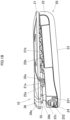
FIG.4 is a sectional view of the sensor device according to the embodiment of the present disclosure taken along a line IV-IV inFIG. 2 . - Referring to the accompanying drawings, an embodiment of the present disclosure will be described. A
sensor device 10 shown inFIGs. 1A ,1B includes amain body portion 20, which is provided into a clip-like configuration by rotatably coupling a firstmain body portion 21 and a secondmain body portion 22 together. Themain body portion 20 includes the firstmain body portion 21 and the secondmain body portion 22. Thesensor device 10 is mounted on a body of auser 100 by holding an edge portion 121 (a rubber portion at the waist, a holding member) of clothing 120 (training pants inFIG. 2 ) worn by theuser 100 using the clip-likemain body portion 20, as shown inFIG. 2 . Here, theedge portion 121, which constitutes the holding member, is such as to be worn by theuser 100 at a certain part of the body of theuser 100, and in the present embodiment, theedge portion 121 is worn by theuser 100 at a waist part of theuser 100. Then, the firstmain body portion 121 is disposed on an outer side of the clothing 120 (an outer side of the holding member which is an opposite side to a side facing the certain part of the body or an opposite side to a side facing the body of the user 100), and the secondmain body portion 22 is disposed on an inner side of the closing 120 (an inner side which is the side of the holding member which faces the certain part of the body or the side which faces the body of the user 100). A contact surface 23 (refer toFIG. 1B ) is provided on the secondmain body portion 22. Thecontact surface 23 is provided on a surface of the secondmain body portion 22. - The
sensor device 10 can be used by bringing thecontact surface 23 into contact with askin 110 on a back side of theuser 100. When theuser 100 takes exercise such as running, a movement of the body of theuser 100, who is running, is detected and transmitted by ameasuring unit 512 and acommunication unit 524, respectively, which are possessed by thesensor device 10, so that the movement so detected and transmitted is analyzed at a terminal device such as a smartphone. Themeasuring unit 512 and thecommunication unit 524 will be described in detail later on. - In the following description, when referring to an up-down direction, a left-right direction, and a front-rear direction of the
sensor device 10, those directions are so referred to in such a state that thesensor device 10 is mounted on the body of theuser 100 as described before. In the case of the up-down direction, an end of thesensor device 10 directed towards the head of theuser 100 is referred to up, while an end of thesensor device 10 directed towards the legs of theuser 100 is referred to as down. In the case of the left-right direction, a lateral side of thesensor device 10 directed to the left arm of theuser 100 is referred to as left, while a lateral side of thesensor device 10 directed towards the right arm of theuser 100 is referred to as right. In the case of the front-rear direction, a side of thesensor device 10 which is to be in contact with theskin 110 of theuser 100 is referred to as front, while a side of thesensor device 10 which is opposite to the front side is referred to as rear, as shown inFIG. 4 . In addition, in the following description, clockwise and counterclockwise rotations are referred to simply as rotation. - As shown in
FIGs. 1A ,1B , thesensor device 10 has a substantially rectangular parallelepiped box-like shape which is long in the up-down direction. In themain body portion 20, the firstmain body portion 21 is provided on a rear side, while the secondmain body portion 22 is provided on a front side. The firstmain body portion 21 and the secondmain body portion 22 each have a substantially flat plate-like shape with flat surfaces oriented in the front-rear direction and are coupled together at ahinge portion 35, which is provided at an upper side of themain body portion 20. - The
hinge portion 35 has arotational shaft 35a. Therotational shaft 35a is passed through a bearing hole of a first bearing 21a, which projects from an upper portion on a front surface of the firstmain body portion 21, and a bearing hole of a second bearing 22a, which projects from an upper portion on a rear surface of the secondmain body portion 22, so as to couple the firstmain body portion 21 and the secondmain body portion 22 together in a rotatable fashion. - A torsion coil spring35b (refer to
FIG. 4 ) is wound around a substantially central portion, in the left-right direction, of therotational shaft 35a. As a result, the firstmain body portion 21 and the secondmain body portion 22, which are detachably attached to theedge portion 121, are biased so that portions which lie lower than therotational shaft 35a move towards each other, whereby thesensor device 10 can be fixedly held to theuser 100 via theclothing 120 by holding theedge portion 121 of theclothing 120 with the relevant lower portions of the firstmain body portion 21 and the secondmain body portion 22. -
Multiple projections main body portion 21 and the rear surface of the secondmain body portion 22, respectively, so that theprojections closing 120 so as to hold theclosing 120 therebetween when theclothing 120 is held by the firstmain body portion 21 and the secondmain body portion 22. - A
lock component 36 is provided at an upper end portion of the firstmain body portion 21. Thelock component 36 includes a projectingportion 36b, which is provided on a front surface of a flat plate-likemain body portion 36a thereof. Anengagement hole 36c (refer toFIG. 4 ), which has an elongated hole-like shape, is provided in each of left- and right-hand sides of the projectingportion 36b. Therotational shaft 35a is passed through theengagement hole 36c for engagement therewith. - On the other hand, a push-up projecting
portion 22c is provided at an upper end portion on the rear surface of the secondmain body portion 22 which lies opposite to thelock component 36 on the firstmain body portion 21. Thelock component 36 is provided on the firstmain body portion 21 in such a manner as to move in theengagement hole 36c, which is formed into the elongated hole, in a longitudinal direction (substantially in the up-down direction) of theengagement hole 36c. When theuser 100 operates thelock component 36 in such a manner as to move downwards, the projectingportion 36b is brought into abutment with the push-upportion 22c and then rides on the push-upportion 22c. As a result, even though the firstmain body portion 21 is caused to move towards the secondmain body portion 22 at an upper side than therotational shaft 35a (that is, the firstmain body portion 21 is caused to move away or open from the secondmain body portion 22 at a lower side than therotational shaft 35a), since the projectingportion 36b is in abutment with the push-upportion 22c, the firstmain body portion 21 is restricted from moving towards the secondmain body portion 22. In this way, the rotation of the secondmain body portion 22 about therotational shaft 35a relative to the first main body portion is locked. To release the locked rotation of the secondmain body 22, thelock component 36 is moved upwards to release the state in which the projectingportion 36b rides on the push-upportion 22c. When the secondmain body portion 22 is released from the rotation-locked state, the firstmain body portion 21 can rotate about therotational shaft 35a. - The second
main body portion 22 has a substantially rectangular parallelepiped box-like shape which is long in the up-down direction and thick in the front-rear direction. The secondmain body portion 22 is formed as a case for accommodating a circuit board 50 (refer toFIG. 4 ) including a part of a circuit unit 500 (refer toFIG. 3 ), a battery (not shown) which constitutes a power supply, and the like. The front surface of the secondmain body portion 22 constitutes thecontact surface 23 which can be brought into contact with theskin 110 of theuser 100, while a rear surface of the secondmain body portion 22 faces a front surface of the firstmain body portion 21 with a slight gap defined therebetween. Thecontact surface 23 is described as being a flat surface but may be a curved surface. - A
button switch 24, which functions as anoperation unit 518, and twoLEDs display unit 516, are provided on an upper surface of the secondmain body portion 22. When theuser 100 operates and pushes down thebutton switch 24, operations can be performed such as supplying power to thesensor device 10, causing ameasuring unit 512 to start detection, and the like, and a status of thesensor device 10 such as an operation mode or the like is indicated by illumination states of theLEDs lid portion 26 is provided on a lower surface of the secondmain body portion 22 so as to cover a USB terminal (not shown). - Next, referring to
FIG. 3 , a control circuit of thesensor device 10 will be described. Thecircuit unit 500, which is provided in the secondmain body portion 22 of themain body portion 20 of thesensor device 10, includes aprocessor 510, the measuringunit 512, thedisplay unit 516, theoperation unit 518, astorage unit 514, a positionalinformation detection unit 520, an environmentalinformation detection unit 522, and thecommunication unit 524. These units are connected to theprocessor 510 by way of buses BS. - On the other hand, an
antenna 530, which is configured to receive and transmit radio waves, is provided in the firstmain body portion 21 of the sensor device 10 (refer toFIG. 4 ) . Theantenna 530 is electrically connected to thecircuit board 50, which includes the part of thecircuit unit 500, by way of signal lines 51. Specifically, theantenna 530 is connected to theprocessor 510 by way of thecommunication unit 524 and is connected to the positionalinformation detection unit 520 by way of thesignal line 51, so that theantenna 530 can output a reception signal received from an outside device to theprocessor 510 by way of the positionalinformation detection unit 520 and thecommunication unit 524. In addition, theantenna 530 can output a transmission signal to the outside device by way of the positionalinformation detection unit 520 and thecommunication unit 524, which are controlled by theprocessor 510. In this way, theantenna 530 can communicate with the outside device. The outside device includes a terminal device such as a smartphone and a positioning satellite adopting the Global Navigation Satellite System (GNSS). - The
processor 510 is made up of a Central Processing unit (CPU), which functions as at least one processor, a microcomputer, or the like and executes various types of processing by reading out programs stored in thestorage unit 514. Thestorage unit 514 is made up of a flash memory, which functions as at least one memory, an Electrically Erasable Programmable ROM (EEPROM), and the like. - The
storage unit 514 stores system programs and application programs that theprocessor 510 executes, as well as data necessary for theprocessor 510 to execute these programs. The measuringunit 512 measures information on theuser 100. The measuringunit 512 has amotion sensor unit 512a and a vitalinformation sensor unit 512b. Themotion sensor unit 512a includes sensor elements such as a three-axis acceleration sensor, a gyro-sensor, a terrestrial magnetic sensor, and the like and can detect a movement of the subject unit (the sensor device 10) as a movement of a waist part of theuser 100 who wears thesensor device 10, so that themotion sensor unit 512a outputs a detection signal so detected to theprocessor 510. The vitalinformation sensor unit 512b includes various types of sensors for obtaining pulses of theuser 100 and outputs a detection signal to theprocessor 510. - The
display unit 516 includes theLEDs main body portion 20. Theoperation unit 518 includes, for example, thebutton switch 24 and outputs an operation signal, which indicates an operation state of thebutton switch 24 by theuser 100, to theprocessor 510. Illumination states of theLEDs processor 510 in accordance with the operation signal indicating the operation state of thebutton switch 24 by theuser 100. - The positional
information detection unit 20 includes a Large Scale Integration (LSI) circuit having CPU, a memory, a filter, a modulator/demodulator, and the like and can derive positional information data of thesensor device 10 based on a reception signal from the positioning satellite received by way of theantenna 530, so that the positional information data so derived is output to theprocessor 510. - The environmental
information detection unit 522 includes, for example, an atmospheric pressure sensor for measuring an atmospheric pressure at a place where the sensor device 10 (the main body portion 20) is located, and a detection signal detected by the environmentalinformation detection unit 522 is output to theprocessor 510. - The
communication unit 524 includes a circuit for transmitting and receiving a signal to and from the outside device (the terminal device) by way of theantenna 530 in a predetermined radio or wireless system, and this circuit has a filter, an amplifier, and a modulator/demodulator. The predetermined radio or wireless system is, for example, Bluetooth (a registered trademark), Bluetooth Law Energy (BLE) from Version 4 on of Bluetooth (the registered trademark), or the like. Thecommunication unit 524 processes a transmission signal which is input from theprocessor 510, amplifies the transmission signal so processed, modulates the transmission signal so amplified, and transmits it to the outside device (the terminal device) by way of theantenna 530. In addition, thecommunication unit 524 demodulates a reception signal received by way of theantenna 530, amplifies the reception signal so demodulated, processes the reception signal so amplified, and outputs it to theprocessor 510. - The
processor 510 executes various processing based on the detection signal detected by the measuring unit 512 (themotion sensor unit 512a, the vitalinformation sensor module 512b), the positional information data obtained by the positionalinformation detection unit 520, the detection signal detected by the environmentalinformation detection unit 522 to thereby derive indexed data representing moving states of theuser 100 such as a speed, a pitch, a stride, a vertical motion of the waist of theuser 100 who is running or walking, and transmits the indexed data so derived as transmission signals to the outside device (the terminal device) by way of thecommunication unit 524. The outside device (the terminal device), for example, analyzes the movement of theuser 100 based on the indexed data so transmitted. - In addition, as shown in
FIG. 4 , themain body portion 20 includesguide passages 55, which are formed of a through hole or a groove portion in the firstmain body portion 21 and the secondmain body portion 22, and thesignal lines 51 are guided through theguide passages 55. The signal lines 55 electrically connect thecircuit board 50, which includes the part of thecircuit unit 500, and theantenna 530 together. Theantenna 530 may include separately an antenna connected with the positionalinformation detection unit 520 and an antenna connected with thecommunication unit 524. - When the
sensor device 10 is attached to the closing 120, the firstmain body portion 21 is disposed on the outer side of the closing 120 (the edge portion 121), while the secondmain body portion 22 is disposed on the inner side of theclosing 120. That is, theantenna 530 is disposed on the outer side of theclosing 120. As a result, even if the closing 120 gets wet due to sweat exuded from theskin 110 of theuser 100 as a result of movement or exercise, or rain, theantenna 530 is prevented from being held by the body of theuser 100 which gets wet due to the sweat and thewet clothing 120 therebetween or is prevented from being covered with thewet closing 120, whereby the sensitivity of theantenna 530 is maintained in a good condition. - Thus, while the embodiment of the present disclosure has been described heretofore, the present disclosure is never limited by the embodiment so described, and hence, the present disclosure can be carried out while being modified variously. For example, while the
circuit unit 500 is described as being provided in the secondmain body portion 22, the present disclosure is not limited thereto, and hence, a configuration may be adopted in which a second circuit unit including the measuring unit 512 (themotion sensor unit 512a) and theprocessor 510 is provided in the secondmain body portion 22, while the positionalinformation detection unit 520 and the communication unit 524 (or one part of elements of the positionalinformation detection unit 520 and one part of elements of the communication unit 524), as well as theantenna 530 are provided in the firstmain body portion 21. In the case that the one part of the elements of the positionalinformation detection unit 520 and the one part of the elements of thecommunication unit 524 are provided in the firstmain body portion 21, the other parts of the positionalinformation detection unit 520 and thecommunication unit 524 are provided in a first circuit unit. - The holding member is not limited to the
edge portion 121 of the closing 120, and hence, the holding member can be a belt or the like. In addition, thesensor device 10 can be attached to a certain part of the body of theuser 100 other than the back of the body. While a clip-like attaching portion is adopted in the present embodiment, an attaching portion which is fixed with a fastening tool such as a snap button or a button may be adopted for the holding member. For example, thesensor device 10 can also be fastened to a belt or the like with a snap button. - Thus, according to the embodiments of the present disclosure, the
sensor device 10 has the firstmain body portion 21 and the secondmain body portion 22, which are configured to be detachably attached to theedge portion 121 of the closing 120 which constitutes the holding member worn on a certain part of the body of theuser 100. The firstmain body portion 21 is disposed on the outer side of theedge portion 121 which lies opposite to the side facing the waist part constituting the certain part of the body, and theantenna 530 for receiving or transmitting a radio wave is provided in the firstmain body portion 21. The secondmain body portion 22 is disposed on the inner side of theedge portion 121 which is the side facing the waist part constituting the certain part of the body, and thecircuit unit 500 including the measuringunit 512 for measuring the information on theuser 100 is provided in the second main body portion. As a result, the sensitivity of theantenna 530 can be improved irrespective of the states of the clothing 120 (whether the closing 120 is in the wet state due to sweat or in the dry state). - The first
main body portion 21 and the secondmain body portion 22 constitute the clip-like configuration by being coupled together rotatably. As a result, thesensor device 10 can easily be attached to the holding member. In addition, thecircuit unit 500 further includes theprocessor 510, the positionalinformation detection unit 520, and thecommunication unit 524. As a result, thesensor device 10 can easily be controlled. The measuringunit 512 includes the vitalinformation sensor unit 512b for obtaining pulses and themotion sensor unit 512a for measuring the movement of the subject device. As a result, the motion and the status of the body when the high-degree movement is made can be analyzed. In addition, the secondmain body portion 22 includes thecircuit board 50 which includes at least the part of thecircuit unit 500. As a result, the individual units of thecircuit unit 500 are accommodated in the secondmain body portion 22, and the measuringunit 512 for measuring the information on theuser 100 is disposed close to at least the body, thereby making it possible to detect the information of the user with good precision. - In addition, the
circuit unit 500 has the first circuit unit which is provided in the firstmain body portion 21 and which includes the positionalinformation detection unit 520 and thecommunication unit 524 and the second circuit unit which is provided in the secondmain body portion 22 of themain body portion 20 which is disposed on the inner side of theclothing 120 and which includes the measuringunit 512 and theprocessor 510. As a result, the secondmain body portion 22, which is disposed close to the body, can be formed thin. - The first
main body portion 21 and the secondmain body portion 22 have theguide passages 55 for guiding thesignal lines 51 which electrically connect theantenna 530 with thecircuit board 50. As a result, thesignal lines 51 can be protected, while allowing theantenna 530 and thecircuit board 50 to be connected electrically together in a proper fashion. - The second
main body portion 22 includes thecontact surface 23, which is configured to be in contact with the body of theuser 100, on the surface which lies opposite to the surface facing the firstmain body portion 21. As a result, the secondmain body portion 22 including the measuringunit 512 is allowed to be brought into contact with the body on thecontact surface 23, thereby making it possible to increase the measuring accuracy of the information on theuser 100. - In addition, the
circuit unit 500 includes the environmentalinformation detection unit 522 for detecting an environment around themain body portion 20. As a result, a movement environment at the time of data collection can be recorded. - While the present disclosure has been described with reference to the exemplary embodiments, it is to be understood that the present disclosure is not limited to the disclosed exemplary embodiments. The scope of the following claims is to be accorded the broadest interpretation so as to encompass all such modifications and equivalent structures and functions.
Claims (9)
- A sensor device (10) comprising:a first main body portion (21) and a second main body portion (22) which are configured to be detachably attached to a holding member worn by a user (100),wherein the first main body portion (21) is disposed on a side of the holding member which lies opposite to a side facing a body of the user (100) and includes therein an antenna (530) for receiving or transmitting a radio wave, andwherein the second main body portion (22) is disposed on the side of the holding member which lies to face the body of the user (100) and includes therein a circuit unit (500) including a measuring unit (512) configured to measure information of the user (100).
- The sensor device (10) according to claim 1,
wherein the first main body portion (21) and the second main body portion (22) are provided into a clip-like configuration by being coupled together rotatably. - The sensor device (10) according to claim 1 or 2,
wherein the circuit unit (500) further comprises a processor (510), a positional information detection unit (520), and a communication unit (524). - The sensor device (10) according to claim 3,
wherein the circuit unit (500) comprises a first circuit unit provided in the first main body portion (21) and including the positional information detection unit (520) and the communication unit (524) and a second circuit unit provided in the second main body portion (22) and including the measuring unit (512) and the processor (510). - The sensor device (10) according to any one of claims 1 to 4,
wherein the measuring unit (512) comprises a vital information sensor unit (512b) configured to obtain a pulse and a motion sensor unit (512a) configured to measure a movement of a subject device. - The sensor device (10) according to any one of claims 1 to 5,
wherein the second main body portion (22) comprises a circuit board (50) including therein at least a part of the circuit unit (500). - The sensor device (10) according to claim 6,
wherein the first main body portion (21) and the second main body portion (22) have a guide passage (55) configured to guide a signal line (51) which connects the antenna (530) with the circuit board (50). - The sensor device (10) according to any one of claims 1 to 7,
wherein the second main body portion (22) comprises a contact surface (23) provided on an opposite side to a side facing the first main body portion (21) and configured to be brought into contact with the body. - The sensor device (10) according to any one of claims 1 to 8,
wherein the circuit unit (500) comprises an environmental information detection unit (522) configured to detect an environment around the sensor device (10).
Applications Claiming Priority (1)
| Application Number | Priority Date | Filing Date | Title |
|---|---|---|---|
| JP2021155046A JP2023046451A (en) | 2021-09-24 | 2021-09-24 | sensor device |
Publications (2)
| Publication Number | Publication Date |
|---|---|
| EP4154801A1 true EP4154801A1 (en) | 2023-03-29 |
| EP4154801B1 EP4154801B1 (en) | 2025-03-05 |
Family
ID=83903317
Family Applications (1)
| Application Number | Title | Priority Date | Filing Date |
|---|---|---|---|
| EP22195583.4A Active EP4154801B1 (en) | 2021-09-24 | 2022-09-14 | Sensor device |
Country Status (4)
| Country | Link |
|---|---|
| US (1) | US20230101759A1 (en) |
| EP (1) | EP4154801B1 (en) |
| JP (1) | JP2023046451A (en) |
| CN (1) | CN115844379A (en) |
Families Citing this family (1)
| Publication number | Priority date | Publication date | Assignee | Title |
|---|---|---|---|---|
| USD995794S1 (en) * | 2021-04-12 | 2023-08-15 | Medwand Solutions, Inc. | Integrated multi-sensored medical device |
Citations (3)
| Publication number | Priority date | Publication date | Assignee | Title |
|---|---|---|---|---|
| US20190365285A1 (en) * | 2017-02-22 | 2019-12-05 | Daikin Industries, Ltd. | Biological information acquisition device |
| US20200060546A1 (en) * | 2017-05-08 | 2020-02-27 | Akash Madnani | A System and Method for Monitoring Human Performance |
| JP2020099413A (en) | 2018-12-20 | 2020-07-02 | 合同会社キンビシャス | Training assistance system |
Family Cites Families (3)
| Publication number | Priority date | Publication date | Assignee | Title |
|---|---|---|---|---|
| JP6635285B2 (en) * | 2015-06-30 | 2020-01-22 | カシオ計算機株式会社 | Electronic device, sensor calibration method, sensor calibration program |
| JP2017169726A (en) * | 2016-03-23 | 2017-09-28 | カシオ計算機株式会社 | Measuring device, measuring method, and measuring program |
| JP2021133221A (en) * | 2020-02-25 | 2021-09-13 | 株式会社コト | Biological motion information acquisition device and biological motion information acquisition system |
-
2021
- 2021-09-24 JP JP2021155046A patent/JP2023046451A/en active Pending
-
2022
- 2022-08-31 US US17/900,585 patent/US20230101759A1/en not_active Abandoned
- 2022-09-13 CN CN202211112681.1A patent/CN115844379A/en active Pending
- 2022-09-14 EP EP22195583.4A patent/EP4154801B1/en active Active
Patent Citations (3)
| Publication number | Priority date | Publication date | Assignee | Title |
|---|---|---|---|---|
| US20190365285A1 (en) * | 2017-02-22 | 2019-12-05 | Daikin Industries, Ltd. | Biological information acquisition device |
| US20200060546A1 (en) * | 2017-05-08 | 2020-02-27 | Akash Madnani | A System and Method for Monitoring Human Performance |
| JP2020099413A (en) | 2018-12-20 | 2020-07-02 | 合同会社キンビシャス | Training assistance system |
Also Published As
| Publication number | Publication date |
|---|---|
| JP2023046451A (en) | 2023-04-05 |
| US20230101759A1 (en) | 2023-03-30 |
| CN115844379A (en) | 2023-03-28 |
| EP4154801B1 (en) | 2025-03-05 |
Similar Documents
| Publication | Publication Date | Title |
|---|---|---|
| EP2405799B1 (en) | Data transfer | |
| JP5928817B2 (en) | Biological information measuring device and operation method thereof | |
| US10258280B2 (en) | Wearable electronic device | |
| US20130053661A1 (en) | System for enabling reliable skin contract of an electrical wearable device | |
| EP4154801B1 (en) | Sensor device | |
| US12193412B2 (en) | Animal wearable tracker device and related methods | |
| US20090093992A1 (en) | Pedometer | |
| CN108692762B (en) | Detection device | |
| CN104042203B (en) | Portable electronic device | |
| US20090198110A1 (en) | Biological Information Acquisition Telemetry System | |
| JP6760547B2 (en) | Helmet | |
| US20180070154A1 (en) | Motion detecting apparatus and motion detecting system | |
| JPH06242206A (en) | Emergent aid system | |
| JP7746766B2 (en) | Sensor Device | |
| EP3487080B1 (en) | Radio equipment which improves the sensitivity of the near field communication | |
| JP2001070264A (en) | Pulse wave sensor | |
| CN114721247A (en) | Wearable device | |
| CN110996656A (en) | Wearing equipment and how to wear it | |
| JP2019092910A (en) | Biological information detector | |
| US20160131167A1 (en) | Motion detection device | |
| KR102097425B1 (en) | Pant for Infant having Function of Preventing Missing Child and Function of Regulating Length in Waist Circumference | |
| EP4527238A1 (en) | Wearable electronic apparatus including strap fastening device | |
| US20200060552A1 (en) | Body surface temperature measurement device | |
| KR20200022796A (en) | Detachable Wearable Device Including Flexible Patch | |
| CN211559005U (en) | Wearable device |
Legal Events
| Date | Code | Title | Description |
|---|---|---|---|
| PUAI | Public reference made under article 153(3) epc to a published international application that has entered the european phase |
Free format text: ORIGINAL CODE: 0009012 |
|
| STAA | Information on the status of an ep patent application or granted ep patent |
Free format text: STATUS: REQUEST FOR EXAMINATION WAS MADE |
|
| 17P | Request for examination filed |
Effective date: 20220920 |
|
| AK | Designated contracting states |
Kind code of ref document: A1 Designated state(s): AL AT BE BG CH CY CZ DE DK EE ES FI FR GB GR HR HU IE IS IT LI LT LU LV MC MK MT NL NO PL PT RO RS SE SI SK SM TR |
|
| STAA | Information on the status of an ep patent application or granted ep patent |
Free format text: STATUS: EXAMINATION IS IN PROGRESS |
|
| 17Q | First examination report despatched |
Effective date: 20231024 |
|
| RIC1 | Information provided on ipc code assigned before grant |
Ipc: A61B 5/11 20060101ALN20240103BHEP Ipc: A61B 5/00 20060101AFI20240103BHEP |
|
| GRAP | Despatch of communication of intention to grant a patent |
Free format text: ORIGINAL CODE: EPIDOSNIGR1 |
|
| STAA | Information on the status of an ep patent application or granted ep patent |
Free format text: STATUS: GRANT OF PATENT IS INTENDED |
|
| INTG | Intention to grant announced |
Effective date: 20241105 |
|
| RIC1 | Information provided on ipc code assigned before grant |
Ipc: A61B 5/11 20060101ALN20241025BHEP Ipc: A61B 5/00 20060101AFI20241025BHEP |
|
| GRAS | Grant fee paid |
Free format text: ORIGINAL CODE: EPIDOSNIGR3 |
|
| GRAA | (expected) grant |
Free format text: ORIGINAL CODE: 0009210 |
|
| STAA | Information on the status of an ep patent application or granted ep patent |
Free format text: STATUS: THE PATENT HAS BEEN GRANTED |
|
| AK | Designated contracting states |
Kind code of ref document: B1 Designated state(s): AL AT BE BG CH CY CZ DE DK EE ES FI FR GB GR HR HU IE IS IT LI LT LU LV MC MK MT NL NO PL PT RO RS SE SI SK SM TR |
|
| REG | Reference to a national code |
Ref country code: GB Ref legal event code: FG4D |
|
| REG | Reference to a national code |
Ref country code: CH Ref legal event code: EP |
|
| REG | Reference to a national code |
Ref country code: IE Ref legal event code: FG4D |
|
| REG | Reference to a national code |
Ref country code: DE Ref legal event code: R096 Ref document number: 602022011360 Country of ref document: DE |
|
| PG25 | Lapsed in a contracting state [announced via postgrant information from national office to epo] |
Ref country code: RS Free format text: LAPSE BECAUSE OF FAILURE TO SUBMIT A TRANSLATION OF THE DESCRIPTION OR TO PAY THE FEE WITHIN THE PRESCRIBED TIME-LIMIT Effective date: 20250605 |
|
| PG25 | Lapsed in a contracting state [announced via postgrant information from national office to epo] |
Ref country code: FI Free format text: LAPSE BECAUSE OF FAILURE TO SUBMIT A TRANSLATION OF THE DESCRIPTION OR TO PAY THE FEE WITHIN THE PRESCRIBED TIME-LIMIT Effective date: 20250305 |
|
| REG | Reference to a national code |
Ref country code: NL Ref legal event code: MP Effective date: 20250305 |
|
| PG25 | Lapsed in a contracting state [announced via postgrant information from national office to epo] |
Ref country code: ES Free format text: LAPSE BECAUSE OF FAILURE TO SUBMIT A TRANSLATION OF THE DESCRIPTION OR TO PAY THE FEE WITHIN THE PRESCRIBED TIME-LIMIT Effective date: 20250305 |
|
| REG | Reference to a national code |
Ref country code: LT Ref legal event code: MG9D |
|
| PG25 | Lapsed in a contracting state [announced via postgrant information from national office to epo] |
Ref country code: NO Free format text: LAPSE BECAUSE OF FAILURE TO SUBMIT A TRANSLATION OF THE DESCRIPTION OR TO PAY THE FEE WITHIN THE PRESCRIBED TIME-LIMIT Effective date: 20250605 |
|
| PG25 | Lapsed in a contracting state [announced via postgrant information from national office to epo] |
Ref country code: HR Free format text: LAPSE BECAUSE OF FAILURE TO SUBMIT A TRANSLATION OF THE DESCRIPTION OR TO PAY THE FEE WITHIN THE PRESCRIBED TIME-LIMIT Effective date: 20250305 |
|
| PG25 | Lapsed in a contracting state [announced via postgrant information from national office to epo] |
Ref country code: LV Free format text: LAPSE BECAUSE OF FAILURE TO SUBMIT A TRANSLATION OF THE DESCRIPTION OR TO PAY THE FEE WITHIN THE PRESCRIBED TIME-LIMIT Effective date: 20250305 |
|
| PG25 | Lapsed in a contracting state [announced via postgrant information from national office to epo] |
Ref country code: BG Free format text: LAPSE BECAUSE OF FAILURE TO SUBMIT A TRANSLATION OF THE DESCRIPTION OR TO PAY THE FEE WITHIN THE PRESCRIBED TIME-LIMIT Effective date: 20250305 Ref country code: GR Free format text: LAPSE BECAUSE OF FAILURE TO SUBMIT A TRANSLATION OF THE DESCRIPTION OR TO PAY THE FEE WITHIN THE PRESCRIBED TIME-LIMIT Effective date: 20250606 |
|
| REG | Reference to a national code |
Ref country code: AT Ref legal event code: MK05 Ref document number: 1772123 Country of ref document: AT Kind code of ref document: T Effective date: 20250305 |
|
| PG25 | Lapsed in a contracting state [announced via postgrant information from national office to epo] |
Ref country code: NL Free format text: LAPSE BECAUSE OF FAILURE TO SUBMIT A TRANSLATION OF THE DESCRIPTION OR TO PAY THE FEE WITHIN THE PRESCRIBED TIME-LIMIT Effective date: 20250305 |
|
| PG25 | Lapsed in a contracting state [announced via postgrant information from national office to epo] |
Ref country code: SE Free format text: LAPSE BECAUSE OF FAILURE TO SUBMIT A TRANSLATION OF THE DESCRIPTION OR TO PAY THE FEE WITHIN THE PRESCRIBED TIME-LIMIT Effective date: 20250305 |
|
| PG25 | Lapsed in a contracting state [announced via postgrant information from national office to epo] |
Ref country code: SM Free format text: LAPSE BECAUSE OF FAILURE TO SUBMIT A TRANSLATION OF THE DESCRIPTION OR TO PAY THE FEE WITHIN THE PRESCRIBED TIME-LIMIT Effective date: 20250305 |
|
| PG25 | Lapsed in a contracting state [announced via postgrant information from national office to epo] |
Ref country code: PT Free format text: LAPSE BECAUSE OF FAILURE TO SUBMIT A TRANSLATION OF THE DESCRIPTION OR TO PAY THE FEE WITHIN THE PRESCRIBED TIME-LIMIT Effective date: 20250707 |
|
| PGFP | Annual fee paid to national office [announced via postgrant information from national office to epo] |
Ref country code: DE Payment date: 20250730 Year of fee payment: 4 |
|
| PG25 | Lapsed in a contracting state [announced via postgrant information from national office to epo] |
Ref country code: PL Free format text: LAPSE BECAUSE OF FAILURE TO SUBMIT A TRANSLATION OF THE DESCRIPTION OR TO PAY THE FEE WITHIN THE PRESCRIBED TIME-LIMIT Effective date: 20250305 Ref country code: IT Free format text: LAPSE BECAUSE OF FAILURE TO SUBMIT A TRANSLATION OF THE DESCRIPTION OR TO PAY THE FEE WITHIN THE PRESCRIBED TIME-LIMIT Effective date: 20250305 |
|
| PG25 | Lapsed in a contracting state [announced via postgrant information from national office to epo] |
Ref country code: AT Free format text: LAPSE BECAUSE OF FAILURE TO SUBMIT A TRANSLATION OF THE DESCRIPTION OR TO PAY THE FEE WITHIN THE PRESCRIBED TIME-LIMIT Effective date: 20250305 |
|
| PGFP | Annual fee paid to national office [announced via postgrant information from national office to epo] |
Ref country code: FR Payment date: 20250808 Year of fee payment: 4 |
|
| PG25 | Lapsed in a contracting state [announced via postgrant information from national office to epo] |
Ref country code: EE Free format text: LAPSE BECAUSE OF FAILURE TO SUBMIT A TRANSLATION OF THE DESCRIPTION OR TO PAY THE FEE WITHIN THE PRESCRIBED TIME-LIMIT Effective date: 20250305 Ref country code: CZ Free format text: LAPSE BECAUSE OF FAILURE TO SUBMIT A TRANSLATION OF THE DESCRIPTION OR TO PAY THE FEE WITHIN THE PRESCRIBED TIME-LIMIT Effective date: 20250305 |
|
| PG25 | Lapsed in a contracting state [announced via postgrant information from national office to epo] |
Ref country code: RO Free format text: LAPSE BECAUSE OF FAILURE TO SUBMIT A TRANSLATION OF THE DESCRIPTION OR TO PAY THE FEE WITHIN THE PRESCRIBED TIME-LIMIT Effective date: 20250305 |
|
| PG25 | Lapsed in a contracting state [announced via postgrant information from national office to epo] |
Ref country code: SK Free format text: LAPSE BECAUSE OF FAILURE TO SUBMIT A TRANSLATION OF THE DESCRIPTION OR TO PAY THE FEE WITHIN THE PRESCRIBED TIME-LIMIT Effective date: 20250305 |
|
| PG25 | Lapsed in a contracting state [announced via postgrant information from national office to epo] |
Ref country code: IS Free format text: LAPSE BECAUSE OF FAILURE TO SUBMIT A TRANSLATION OF THE DESCRIPTION OR TO PAY THE FEE WITHIN THE PRESCRIBED TIME-LIMIT Effective date: 20250705 |
|
| REG | Reference to a national code |
Ref country code: DE Ref legal event code: R097 Ref document number: 602022011360 Country of ref document: DE |
|
| PLBE | No opposition filed within time limit |
Free format text: ORIGINAL CODE: 0009261 |
|
| STAA | Information on the status of an ep patent application or granted ep patent |
Free format text: STATUS: NO OPPOSITION FILED WITHIN TIME LIMIT |
|
| PG25 | Lapsed in a contracting state [announced via postgrant information from national office to epo] |
Ref country code: DK Free format text: LAPSE BECAUSE OF FAILURE TO SUBMIT A TRANSLATION OF THE DESCRIPTION OR TO PAY THE FEE WITHIN THE PRESCRIBED TIME-LIMIT Effective date: 20250305 |
|
| REG | Reference to a national code |
Ref country code: CH Ref legal event code: L10 Free format text: ST27 STATUS EVENT CODE: U-0-0-L10-L00 (AS PROVIDED BY THE NATIONAL OFFICE) Effective date: 20260114 |
|
| 26N | No opposition filed |
Effective date: 20251208 |
|
| REG | Reference to a national code |
Ref country code: CH Ref legal event code: H13 Free format text: ST27 STATUS EVENT CODE: U-0-0-H10-H13 (AS PROVIDED BY THE NATIONAL OFFICE) Effective date: 20260504 |