EP4154767A1 - Reclining device and seat - Google Patents
Reclining device and seat Download PDFInfo
- Publication number
- EP4154767A1 EP4154767A1 EP22759255.7A EP22759255A EP4154767A1 EP 4154767 A1 EP4154767 A1 EP 4154767A1 EP 22759255 A EP22759255 A EP 22759255A EP 4154767 A1 EP4154767 A1 EP 4154767A1
- Authority
- EP
- European Patent Office
- Prior art keywords
- connecting rod
- bush
- cam
- internal gear
- insertion hole
- Prior art date
- Legal status (The legal status is an assumption and is not a legal conclusion. Google has not performed a legal analysis and makes no representation as to the accuracy of the status listed.)
- Granted
Links
Images




Classifications
-
- B—PERFORMING OPERATIONS; TRANSPORTING
- B60—VEHICLES IN GENERAL
- B60N—SEATS SPECIALLY ADAPTED FOR VEHICLES; VEHICLE PASSENGER ACCOMMODATION NOT OTHERWISE PROVIDED FOR
- B60N2/00—Seats specially adapted for vehicles; Arrangement or mounting of seats in vehicles
- B60N2/02—Seats specially adapted for vehicles; Arrangement or mounting of seats in vehicles the seat or part thereof being movable, e.g. adjustable
- B60N2/22—Seats specially adapted for vehicles; Arrangement or mounting of seats in vehicles the seat or part thereof being movable, e.g. adjustable the back-rest being adjustable
- B60N2/235—Seats specially adapted for vehicles; Arrangement or mounting of seats in vehicles the seat or part thereof being movable, e.g. adjustable the back-rest being adjustable by gear-pawl type mechanisms
- B60N2/2356—Seats specially adapted for vehicles; Arrangement or mounting of seats in vehicles the seat or part thereof being movable, e.g. adjustable the back-rest being adjustable by gear-pawl type mechanisms with internal pawls
- B60N2/236—Seats specially adapted for vehicles; Arrangement or mounting of seats in vehicles the seat or part thereof being movable, e.g. adjustable the back-rest being adjustable by gear-pawl type mechanisms with internal pawls linearly movable
-
- B—PERFORMING OPERATIONS; TRANSPORTING
- B60—VEHICLES IN GENERAL
- B60N—SEATS SPECIALLY ADAPTED FOR VEHICLES; VEHICLE PASSENGER ACCOMMODATION NOT OTHERWISE PROVIDED FOR
- B60N2/00—Seats specially adapted for vehicles; Arrangement or mounting of seats in vehicles
- B60N2/02—Seats specially adapted for vehicles; Arrangement or mounting of seats in vehicles the seat or part thereof being movable, e.g. adjustable
- B60N2/22—Seats specially adapted for vehicles; Arrangement or mounting of seats in vehicles the seat or part thereof being movable, e.g. adjustable the back-rest being adjustable
- B60N2/235—Seats specially adapted for vehicles; Arrangement or mounting of seats in vehicles the seat or part thereof being movable, e.g. adjustable the back-rest being adjustable by gear-pawl type mechanisms
-
- B—PERFORMING OPERATIONS; TRANSPORTING
- B60—VEHICLES IN GENERAL
- B60N—SEATS SPECIALLY ADAPTED FOR VEHICLES; VEHICLE PASSENGER ACCOMMODATION NOT OTHERWISE PROVIDED FOR
- B60N2/00—Seats specially adapted for vehicles; Arrangement or mounting of seats in vehicles
- B60N2/02—Seats specially adapted for vehicles; Arrangement or mounting of seats in vehicles the seat or part thereof being movable, e.g. adjustable
- B60N2/22—Seats specially adapted for vehicles; Arrangement or mounting of seats in vehicles the seat or part thereof being movable, e.g. adjustable the back-rest being adjustable
- B60N2/235—Seats specially adapted for vehicles; Arrangement or mounting of seats in vehicles the seat or part thereof being movable, e.g. adjustable the back-rest being adjustable by gear-pawl type mechanisms
- B60N2/2356—Seats specially adapted for vehicles; Arrangement or mounting of seats in vehicles the seat or part thereof being movable, e.g. adjustable the back-rest being adjustable by gear-pawl type mechanisms with internal pawls
-
- B—PERFORMING OPERATIONS; TRANSPORTING
- B60—VEHICLES IN GENERAL
- B60N—SEATS SPECIALLY ADAPTED FOR VEHICLES; VEHICLE PASSENGER ACCOMMODATION NOT OTHERWISE PROVIDED FOR
- B60N2205/00—General mechanical or structural details
- B60N2205/50—Interlocking shaft arrangements transmitting movement between hinge mechanisms on both sides of a seat
Definitions
- the present invention relates to a reclining device, and a seat including the reclining device.
- Conventional seats for vehicles involve a seat which includes a reclining device for fixing a seatback or backrest at a certain tilt angle in such a manner that the seatback is tiltable to a seat cushion or seat base in a front-rear direction.
- the reclining device includes a pair of reclining mechanisms or recliners arranged on both sides of the seat in a width direction of the seat, and a connecting rod extending in the width direction of the seat and coupled to the reclining mechanisms.
- Each of the reclining mechanisms has a cam coaxially coupled to each of the opposite ends of the connecting rod and being rotatable together with the connecting rod.
- the connecting rod receives a rotational manipulation force from the outside of the seat, the cam rotates together with the connecting rod in a predetermined direction to disconnect a locking plate arranged in the periphery of the cam from an internal gear, thereby achieving lock release.
- each end of the connecting rod is coaxially coupled to the cam, as described above, requires a clearance between an inner surface of a through hole of the cam and an outer surface of the connecting rod.
- a dimensional difference and distortion of a frame assembly i.e., an assembly including: frames of the seatback and the seat cushions; and the reclining mechanisms attached to the frames
- a frame assembly may give unfavorable influence on operability of the reclining mechanisms and a lock load. It is necessary to provide the clearance to accommodate the unfavorable influence.
- the conventional reclining device requiring the clearance between the cam and the connecting rod has drawbacks that the cam and the connecting rod interfere with each other due to bouncing or swaying of a vehicle body, or an impact from the outside, resulting in making an abnormal sound (hitting sound).
- the reclining device disclosed in Patent Literature 1 has a thin elastic ring interposed between the cam and the connecting rod to prevent an occurrence of an abnormal sound while permitting a clearance to exist between the cam and the connecting rod. In this manner, abnormal sound suppression is aimed.
- the elastic ring has a dimension restricted by a width of the clearance between the cam and the connecting rod. This makes it structurally difficult to increase the stiffness of the elastic ring by increasing the thickness of the elastic ring. Increasing the stiffness of the elastic ring for the prevention of abnormal sound under the dimensional restriction of the elastic ring leads to difficulty in inserting the elastic ring into the clearance between the cam and the connecting rod. This results in affecting the assembly of the reclining device. On the other hand, decreasing the stiffness of the elastic ring causes reduction in a holding force of the connecting rod, and thus an abnormal sound occurs even when the connecting rod only slightly shifts and comes into contact with the cam. From these perspectives, it is difficult to achieve effective prevention of abnormal sound while permitting the clearance to exist.
- Patent Literature 1 Japanese Patent Publication Number 3972648
- the present invention has been achieved in view of the circumstances described above, and has an object of providing a reclining device that achieves effective prevention of abnormal sound while permitting a clearance to exist between a cam and a connecting rod.
- a reclining device is a reclining device for holding a seatback to a seat cushion in a tiltable manner and fixing the seatback at a certain tilt angle.
- the reclining device includes: a pair of reclining mechanisms arranged on both sides of a seat in a width direction thereof, and each having an internal gear fixedly attached to a frame of one of the seat cushion and the seatback and a cam arranged in juxtaposition with the internal gear in a thickness direction of the internal gear; a connecting rod extending in the width direction of the seat, coaxially coupled to the cam of each of the reclining mechanisms, and being rotatable together with the cam; and a resin bush having a cylindrical shape formed with a fit hole to receive a fitting part formed on the connecting rod at a portion adjacent to each end of the connecting rod.
- the cam has a rod insertion hole for allowing the end of the connecting rod to be inserted therein.
- the internal gear has a bush insertion hole for allowing the resin bush to be inserted therein at a center position of the internal gear.
- the fitting part adjacent to the end of the connecting rod fits in the fit hole of the resin bush, and the end of the connecting rod protrudes outward of the resin bush.
- the resin bush is placed in the bush insertion hole in contact with an inner surface of the bush insertion hole of the internal gear to retain the connecting rod at such a position to the cam that a clearance exists between an inner surface of the rod insertion hole of the cam and an outer surface of the connecting rod.
- the inner surface of the bush insertion hole has an edge of the bush insertion hole.
- a seat 1 is a vehicle seat, and includes: a seat cushion 2 for supporting buttocks of a seated person; a seatback 3 arranged in the rear of the seat cushion 2 to support the back of the seated person and being tiltable to the seat cushion 2 in a front-rear direction X of the seat 1; a sliding device 4 attached to a lower portion of the seat cushion 2; and a reclining device 5.
- the sliding device 4 is configured to guide the seat cushion 2 slidably in the front-rear direction X of the seat 1, and fixedly hold the seat cushion 2 at a certain position.
- the seat according to the present invention may not indispensably include the sliding device 4.
- the reclining device 5 is configured to fixedly hold the seatback 3 at a certain tilt angle.
- the reclining device 5 includes: a pair of reclining mechanism 6; a connecting rod 7 connected to each of the reclining mechanisms 6; and a pair of resin bushes 8 to each receive a fitting part 7c at a portion adjacent to corresponding one of ends 7b of the connecting rod 7.
- the reclining mechanisms 6 are respectively arranged on both sides of the seat 1 in a width direction Y thereof. Each of the reclining mechanisms 6 serves as a clutch to fixedly hold the seatback 3 at a certain tilt angle.
- the configuration of the reclining mechanism will be described in detail later.
- the reclining mechanism 6 in the embodiment includes: an internal gear 30 fixedly attached to a frame of one of the seat cushion 2 and the seatback 3, that is, to a frame 3a of the seatback 3 (specifically, a side frame forming a side portion of the seatback 3) in the embodiment in a fitting or welding manner; and a cam 50 arranged in juxtaposition with the internal gear 30 in a thickness direction of the internal gear (i.e., in an axial direction S of the connecting rod 7 shown in Fig. 3 ).
- the reclining mechanism 6 may include at least the internal gear 30 and the cam 50, and thus the remaining structural components may be appropriately changed.
- the cam 50 has a rod insertion hole 52a for allowing the end 7b of the connecting rod 7 to be inserted therein.
- the rod insertion hole 52a has a substantially elliptical shape, specifically, a circular shape inwardly narrowing from specific facing sides, in a cross section (in particular, see Fig. 8A and Fig. 9 ).
- the internal gear 30 has a bush insertion hole 35 for allowing the resin bush 8 to be inserted therein through a through hole 3b (see Fig. 3 , and Fig. 6 to Fig. 7 ) formed in the frame 3a at a center position of the internal gear 30.
- the bush insertion hole 35 has a cross-sectionally circular shape.
- the connecting rod 7 is a rod-shaped member extending in the width direction Y of the seat 1 and made of hard material, such as steel.
- the connecting rod 7 specifically has a center part 7a having a cross-sectionally circular shape, the pair of ends 7b on both sides of the center part 7a, and the pair of fitting parts 7c.
- Each end 7b has a shape approximate to a substantially elliptical shape conforming to the substantially elliptical shape of the rod insertion hole 52a (see Fig. 8A and Fig. 9 ) of the cam 50. Specifically, the end 7b has a pair of recesses 7e recessed radially inward at the radially opposite positions to face each other.
- the connecting rod 7 is coaxially coupled to the cam 50 of each of the pair of reclining mechanisms 6 and can rotate together with the cam 50 (see Fig. 6 ).
- a clearance 9 exists between an inner surface 52a1 of the rod insertion hole 52a of the cam 50 and an outer surface 7f of the end 7b of the connecting rod 7 in a state where the end 7b of the connecting rod 7 is placed in the rod insertion hole 52a of the cam 50, in the same manner as a conventional art.
- This configuration can accommodate an unfavorable influence attributed to a dimensional difference and distortion of the frame assembly on the operability of the reclining mechanism 6 and a lock load.
- the fitting part 7c of the connecting rod 7 fits to the resin bush 8 at a portion adjacent to the end 7b (i.e., adjacent to the end 7b at a position closer to the center part 7a or at a position between the center part 7a and the end 7b) on each side of the center part 7a.
- the fitting part 7c has a taper section 7d narrowing as advancing to the end 7b of the connecting rod 7.
- the fitting part 7c has a cross-sectionally circular section 7h (see Fig. 7 and Fig. 8E ) continuous to the center part 7a, a cross-sectionally substantially elliptical section 7g (see Fig. 7 and Fig. 8C ) continuous to the end 7b, and the taper section 7d (see Fig. 7 and Fig. 8D ) connecting the cross-sectionally circular section 7h and the cross-sectionally substantially elliptical section 7g to each other therebetween.
- the cross-sectionally substantially elliptical section 7g also has the recess 7e continuous from the end 7b (see Fig. 5A , Fig. 8A to Fig. 8B ).
- the taper section 7d has such a cross-sectional shape as to gradually change from a circular shape near the cross-sectionally circular section 7h to a substantially elliptical shape conforming to the shape of the end 7b as advancing to the end 7b.
- the resin bush 8 is made of resin material, and includes a cylindrical body having a fit hole 8e, specifically, includes a main body 8a having a cylindrical shape, a flange 8b, and a pair of claws 8d as shown in Fig. 4 .
- the main body 8a, the flange 8b, and the pair of claws 8d are linearly assembled together in the axial direction S (see Fig. 3 ) of the connecting rod 7.
- the resin bush 8 is mainly made of resin material, such as plastic, to prevent an occurrence of an abnormal sound between the connecting rod 7 and the cam 50.
- the material for the resin bush 8 may be substituted by any material having elasticity, such as rubber (e.g., synthetic rubber) and elastomer.
- the material for the resin bush 8 may preferably have characteristics of low contact resistance between the internal gear 30 and the frame 3a, and less abrasion.
- the resin bush 8 has the fit hole 8e to receive the fitting part 7c at a portion adjacent to the end 7b of the connecting rod 7.
- the fit hole 8e axially penetrates the main body 8a and the flange 8b.
- the cylindrical main body 8a extends in the axial direction S of the connecting rod 7 to support the connecting rod 7 in contact with an entire circumference of the connecting rod in the state where the fitting part 7c of the connecting rod 7 fits in the fit hole 8e of the resin bush 8.
- the fit hole 8e of the resin bush 8 has a shape conforming to a contour of the fitting part 7c of the connecting rod 7.
- the fit hole 8e has a cross-sectionally circular hole section 8e1 (see Fig. 7 and Fig. 8E ) conforming to the cross-sectionally circular section 7h of the fitting part 7c, a taper hole section 8e2 (see Fig. 7 and Fig. 8D ) conforming to the taper section 7d, and a cross-sectionally substantially elliptical hole section 8e3 (see Fig. 7 and Fig. 8C ) conforming to the cross-sectionally substantially elliptical section 7g.
- the taper hole section 8e2 has a taper shape fittable onto the taper section 7d of the connecting rod 7 that also has a taper shape. Although a small gap is seen between the taper section 7d and an inner surface of the taper hole section 8e2 in Fig. 7 and Fig. 8D , the small gap may be excludable.
- the flange 8b of the resin bush 8 has a circular plate shape extending radially outward from an end periphery edge (specifically, outer end periphery edge in the axial direction S in Fig. 3 ) of the main body 8a.
- the flange 8b is contactable with the frame 3a (specifically, a surface of the frame 3a opposite to the internal gear 30) of the seatback 3 that is fixedly attached to the internal gear 30 in the axial direction S of the connecting rod 7 in the state where the resin bush 8 is fitted to the fitting part 7c of the connecting rod 7 (see Fig. 3 , and Fig. 6 to Fig. 7 ).
- the pair of claws 8d protrudes outward from a surface of the flange 8b opposite to the main body 8a and extends in the axial direction S of the connecting rod 7 to support the connecting rod 7 on both sides thereof.
- the two claws 8d respectively have facing portions 8d1 facing each other, each facing portion having a shape (e.g., a recessing or protruding shape) fittable onto the cross-sectionally substantially elliptical section 7g of the fitting part 7c of the connecting rod 7.
- each of the facing portions 8d1 has a protruding shape fittable in the corresponding one of the pair of recesses 7e formed in the cross-sectionally substantially elliptical section 7g of the fitting part 7c.
- each of the claws 8d has an outer surface 8d2 opposite to the connecting rod 7, the outer surface having a shape fittable in the bush insertion hole 35 of the internal gear 30.
- the outer surface 8d2 of each of the claws 8d curves in an arc shape so that the claws 8d are fittable in the bush insertion hole 35 (see Fig. 9 ) having a cross-sectionally circular shape.
- the outer surface 8d2 having the arc shape is in surface contact with the inner surface of the bush insertion hole 35 having the cross-sectionally circular shape in the state where the claws 8d fit in the bush insertion hole 35. Consequently, a stable fitting state is attainable.
- the resin bush 8 is fitted to the fitting part 7c adjacent to the end 7b of the connecting rod 7 for coaxially coupling the end 7b of the connecting rod 7 to the reclining mechanism 6, as shown in Fig. 2 to Fig. 3 , and
- the end 7b of the connecting rod 7 and the pair of claws 8d of the resin bush 8 are inserted in the bush insertion hole 35 of the internal gear 30 through the through hole 3b of the frame 3a of the seatback 3.
- the pair of claws 8d is fitted in the bush insertion hole 35 so that the outer surface 8d2 of each of the claws 8d comes into contact with the inner surface and the edge of the bush insertion hole 35.
- the resin bush 8 is placed (specifically, fitted) in the bush insertion hole 35 of the internal gear 30 to retain the connecting rod 7 at such a position to the cam 50 that the clearance 9 exists between the inner surface 52a1 of the rod insertion hole 52a of the cam 50 and the outer surface 7f of the end 7b of the connecting rod 7.
- the outer surface 8d2 of each of the claws 8d may be in contact with at least a part of the inner surface of the bush insertion hole 35, and may not be necessarily in contact with the edge of the inner surface of the bush insertion hole 35.
- the resin bush 8 is rotatable together with the connecting rod 7 and the cam 50 in the state where the pair of claws 8d fits in the bush insertion hole 35 of the internal gear 30.
- the reclining mechanism 6 may include at least the internal gear 30 and the cam 50 in the present invention. Hence, the remaining structural components may be appropriately changed.
- the reclining mechanism 6 is provided between a frame 2a of the seat cushion 2 and the frame 3a of the seatback 3 (see Fig. 2 to Fig. 3 ).
- the reclining mechanism 6 includes a guide bracket 20, the internal gear 30, a spiral spring 40, the cam 50, four locking plates 60A to 60D, and an attachment ring 70.
- the guide bracket 20 is fixed around the rear of the frame 2a (specifically, a side frame) of the seat cushion 2.
- the internal gear 30 is fixed around a lower portion of the frame 3a (specifically, a side frame) of the seatback 3.
- the internal gear 30 may be fixedly attached to the frame 2a of the seat cushion 2
- the guide bracket 20 may be fixedly attached to the frame 3a of the seatback 3.
- the guide bracket 20 has a disc shape, and has an arrangement hole 22 penetrating therethrough at a center thereof for arrangement of the spiral spring 40 therein.
- An inner surface of the arrangement hole 22 is formed with an engagement groove 22a.
- the engagement groove 22a is engaged with an outer end 41 of the spiral spring 40.
- the internal gear 30 has a circular shape in a plan view and further has a cross-sectionally substantially recess shape.
- the internal gear includes a recess section 31 having an inner surface formed with inner teeth 32.
- the recess section 31 faces an inner surface 20a (see Fig. 6 ) of the guide bracket 20.
- the internal gear 30 is coupled to, for example, the frame 3a of the seatback 3 via a connection protrusion 34 protruding in a right depth direction on the paper of Fig. 9 .
- the guide bracket 20 and the internal gear 30 are retained by the attachment ring 70 at such positions that the guide bracket 20 faces the recess section 31 of the internal gear 30 and an end surface 31a1 of a peripheral wall 31a of the recess section 31 comes into contact with a surface of the guide bracket 20.
- the attachment ring 70 has an annular bottom plate 71 having an annular shape with a predetermined width in a substantially circle, and an annular side plate 72 extending in a direction substantially perpendicularly intersecting the outer edge of the annular bottom plate 71, that is, extending along an outer surface 31 a2 of the peripheral wall 31a of the internal gear 30.
- the attachment ring 70 has a substantially L-shape defined by the annular bottom plate 71 and the annular side plate 72 in a radial cross-section.
- the attachment ring 70 covers the guide bracket 20 and the internal gear 30 in such a manner that an end edge 72a of the annular side plate 72 extends over the outer surface 31a2 of the peripheral wall 31a of the internal gear 30 to reach an outer surface 21b of the guide bracket located beyond the outer surface 31a2 (on the left front side of paper of Fig. 9 ) in a state where the guide bracket 20 and the recess section 31 of the internal gear 30 face each other to define an inner space therebetween for accommodating the spiral spring 40, the cam 50, and the lock mechanism including the locking plates 60A to 60D therein.
- the attachment ring 70 rotates together with the guide bracket 20 relative to the internal gear 30.
- the annular side plate 72 of the attachment ring 70 restricts a radial shift of the internal gear 30.
- the annular bottom plate 71 of the attachment ring restricts an axial shift of the internal gear 30.
- the cam 50 is a member for reciprocally moving the locking plates 60A to 60D in a radial direction of the cam 50.
- the cam 50 is provided with four engaging protrusions 51, 51 corresponding to the four locking plates 60A to 60D at equal intervals in a circumferential direction, each engaging protrusion having a horn-like shape extending in a substantially arc.
- a main body 52 of the cam 50, from which the engaging protrusions 51, 51are excluded, is provided with four bulges 52b, 52b each bulging outward to have a larger outer diameter at a predetermined angle from a base part of each of the engaging protrusions 51, 51.
- the cam 50 is integrally fixed to a surface of a spacer 55, and has the rod insertion hole 52a penetrating the center of the cam 50 to receive the end 7b of the connecting rod 7 inserted therein.
- a manipulation member (not shown) attached to the end 7b of the connecting rod 7 is used to rotate the connecting rod 7 forward or backward, the cam 50 rotates in the same direction by following the connecting rod.
- the cam 50 has a first shaft 53 protruding from a periphery of the rod insertion hole 52a toward the guide bracket 20 on a surface facing the guide bracket 20.
- the first shaft 53 has an outer diameter smaller than an inner diameter of the spiral spring 40, and the first shaft 53 is formed with an engagement slit 53a notched from an outer surface of the shaft toward a center thereof.
- the spiral spring 40 is arranged to surround the first shaft 53, and has an inner end 42 engageable with the engagement slit 53a of the first shaft 53 (see Fig. 8A ) so as to be placed in the arrangement hole 22 of the guide bracket 20 together with the first shaft 53.
- the spiral spring 40 urges the cam 50 in one rotational direction due to the engagement of the outer end 41 with the engagement groove 22a on the inner surface of the arrangement hole 22 of the guide bracket 20.
- the internal gear 30 is provided with a second shaft 36 protruding toward the cam 50 at the center of the internal gear.
- the second shaft 36 is inserted in a bearing hole (not shown) formed in the cam 50 to rotatably support the cam 50.
- the four locking plates 60A to 60D are used in the embodiment.
- the four locking plates 60A to 60D are respectively arranged to meet the four engaging protrusions 51, 51 each having a horn-like shape in the cam 50.
- Each of the locking plates 60A to 60D is slidable in a radial direction of the guide bracket 20 along a guide groove (not shown) formed in the guide bracket 20 and extending in the radial direction thereof.
- the locking plates 60A to 60D are urged radially outward in response to a one-directional rotation of the cam 50 attributed to the elasticity of the spiral spring 40, and the locking plates 60A to 60D shift toward the center in response to a reverse-directional rotation of the cam 50 by the connecting rod 7.
- Each of the locking plates 60A to 60D has a substantially rectangular shape in a plan view.
- the locking plates 60A to 60D respectively have engaged grooves 61, 61 each notched in a substantially arc from an inner surface of the corresponding plate.
- the engaging protrusions 51, 51 engage with the corresponding engaged grooves 61, 61 to pull the locking plates 60A to 60D toward the center of the cam 50.
- the engaging protrusions 51, 51 and the bulges 52b, 52b press the locking plates 60A to 60D radially outward of the cam 50.
- the locking plates 60A to 60D have outer surfaces respectively formed with outer teeth 63, 63 to mesh with the inner teeth 32 of the internal gear 30 when the plates are pressed radially outward, thereby locking the guide bracket 20 and the internal gear 30 irrotationally relative to each other. This achieves fixed holding of the seatback 3 at a certain tilt angle.
- the reclining device 5 includes: the pair of reclining mechanisms 6 arranged on both sides of the seat 1 in the width direction Y thereof, and each having the internal gear 30 fixedly attached to the frame of one of the seat cushion 2 and the seatback 3 (to the frame 3a of the seatback 3 in the embodiment), and the cam 50 arranged in juxtaposition with the internal gear 30 in the thickness direction (i.e., width direction Y) of the internal gear; and the connecting rod 7 extending in the width direction Y of the seat 1, coaxially coupled to the cam 50 of each of the reclining mechanisms 6, and being rotatable together with the cam 50.
- the reclining device 5 further includes the resin bush 8 having a cylindrical shape formed with the fit hole 8e to receive the fitting part 7c at a portion adjacent to each end 7b of the connecting rod 7.
- the cam 50 has the rod insertion hole 52a for allowing the end 7b of the connecting rod 7 to be inserted therein.
- the internal gear 30 has the bush insertion hole 35 for allowing the resin bush 8 to be inserted therein at the center position of the internal gear 30.
- the fitting part 7c adjacent to the end 7b of the connecting rod 7 fits in the fit hole 8e of the resin bush 8, and the end 7b of the connecting rod 7 protrudes outward of the resin bush 8.
- the resin bush 8 is placed in the bush insertion hole 35 in contact with the inner surface of the bush insertion hole 35 of the internal gear 30 to retain the connecting rod 7 at such a position to the cam 50 that the clearance 9 exists between the inner surface 52a1 of the rod insertion hole 52a of the cam 50 and the outer surface 7f of the connecting rod 7.
- the resin bush 8 is placed in the bush insertion hole 35 in contact with the inner surface of the bush insertion hole 35 of the internal gear 30 to retain the connecting rod 7 at such a position to the cam 50 that the clearance 9 exists between the inner surface 52a1 of the rod insertion hole 52a of the cam 50 and the outer surface 7f of the connecting rod 7.
- the resin bush 8 restricts the shift of the connecting rod 7 relative to the cam 50 in the radial direction of the cam 50, and thus can prevent an occurrence of a contact sound between the cam 50 and the connecting rod 7. This results in achieving effective prevention of abnormal sound while permitting the clearance 9 to exist between the inner surface 52a1 of the rod insertion hole 52a of the cam 50 and the outer surface 7f of the connecting rod 7.
- the resin bush 8 is not designed to determine relative positions of the cam 50 and the connecting rod 7 by intervening therebetween, but is designed to retain the connecting rod 7 at a specific position in a state of being placed in the bush insertion hole 35 of the internal gear 30. Therefore, the resin bush 8 receives no dimensional restriction due to the clearance 9 between the cam 50 and the connecting rod 7 and no stiffness restriction based on such dimensional restriction. In this respect, the resin bush 8 can be set to a dimension and stiffness leading to less abrasion than those of the elastic ring of the conventional art (structure described in Patent Literature 1).
- the fit hole 8e of the resin bush 8 has a shape conforming to the contour of the fitting part 7c of the connecting rod 7. Specifically, as shown in Fig. 7 and Fig. 8C to Fig. 8E , the fit hole 8e has the cross-sectionally circular hole section 8e1, the taper hole section 8e2, and the cross-sectionally substantially elliptical hole section 8e3.
- a work of attaching the resin bush 8 to the fitting part 7c at a portion of the connecting rod 7 adjacent to the end 7b is completed only by fitting the fitting part 7c adjacent to the end 7b of the connecting rod 7 in the fit hole 8e of the resin bush 8.
- the work has good workability.
- a simple configuration of the connecting rod 7 and the resin bush 8 in combination succeeds in preventing the resin bush 8 from axially coming off the internal gear 30 and further preventing the resin bush 8 from falling off the connecting rod 7.
- the resin bush 8 has the flange 8b coming into contact with the frame 3a of the seatback 3, which is fixedly attached to the internal gear 30, in the axial direction S of the connecting rod 7.
- the flange 8b of the resin bush 8 can restrict the shift of the resin bush 8 in the axial direction S by coming into contact with the frame 3a of the seatback 3 in the axial direction S of the connecting rod 7.
- the flange 8b can prevent an unacceptable matter from entering the reclining mechanism 6 through the through hole 3b by closing a gap between the resin bush 8 and an inner surface of the through hole 3b of the frame 3a.
- the resin bush 8 has the main body 8a extending in the axial direction S of the connecting rod 7 and having a cylindrical shape to support the connecting rod 7 in contact with an entire circumference of the connecting rod.
- the cylindrical main body 8a of the resin bush 8 supports the connecting rod 7 in contact with the entire circumference of the connecting rod, and therefore can further restrict the shit of the connecting rod 7 relative to the cam 50 in the radial direction thereof. As a result, the effect of abnormal sound occurrence prevention is improved.
- the fitting part 7c of the connecting rod 7 has the taper section 7d narrowing as advancing to the end 7b of the connecting rod 7.
- the fit hole 8e of the resin bush 8 has the taper hole section 8e2 fittable to the taper section 7d of the connecting rod 7.
- the taper section 7d formed at the fitting part 7c adjacent to the end 7b of the connecting rod 7 fits to the taper hole section 8e2 of the fit hole 8e of the resin bush 8 to restrict the shift of the resin bush 8 in the axial direction. Furthermore, a simple configuration of the connecting rod 7 and the resin bush 8 in combination succeeds in preventing the resin bush 8 from axially coming off the internal gear 30 and further preventing the resin bush 8 from falling off the connecting rod 7 without increasing the number of components.
- the resin bush 8 has the pair of claws 8d extending in the axial direction S of the connecting rod 7 to support the connecting rod 7 on both sides thereof.
- the claws 8d of the resin bush 8 support the connecting rod 7 on both sides thereof, and therefore can further restrict the shift of the connecting rod 7 relative to the cam 50 in the radial direction. As a result, the effect of abnormal sound occurrence prevention is improved.
- each of the facing portions 8d1 of the claws 8d facing each other has a shape fittable onto the fitting part 7c of the connecting rod 7.
- each of the facing portions 8d1 has a protruding shape fittable in the corresponding recess 7e in the cross-sectionally substantially elliptical section 7g of the fitting part 7c.
- each of the facing portions 8d1 of the claws 8d of the resin bush 8 that face each other fit to the fitting part 7c adjacent to the end 7b of the connecting rod 7, and therefore can further restrict the shift of the connecting rod 7 relative to the cam 50 in the radial direction. As a result, the effect of abnormal sound occurrence prevention is improved.
- each of the claws 8d has the outer surface 8d2 opposite to the connecting rod 7.
- the outer surface 8d2 of each of the two claws 8d has a shape fittable in the bush insertion hole 35 of the internal gear 30.
- the outer surface 8d2 of each claw 8d has an arc shape fittable in the bush insertion hole 35 having the cross-sectionally circular shape.
- the pair of claws 8d of the resin bush 8 can more effectively support the connecting rod 7 on both sides thereof owing to fitting of the pair of claws 8d in the bush insertion hole 35 of the internal gear 30.
- This enables further restriction of the shift of the connecting rod 7 relative to the cam 50 in the radial direction.
- the mere fitting of the pair of claws 8d in the bush insertion hole 35 facilitates determination on the positions of the resin bush 8 and the connecting rod 7, resulting in improvement of the workability in the assembly of the reclining device 5.
- the seat 1 includes: the seat cushion 2; the seatback 3 arranged in the rear of the seat cushion 2 and being tiltable in the front-rear direction X of the seat 1; and the reclining device 5 having the above-described configuration for fixedly holding the seatback 3 at a certain tilt angle.
- the seat 1 includes the reclining device 5 having the configuration where the resin bush 8 is placed in the bush insertion hole 35 in contact with the inner surface of the bush insertion hole 35 of the internal gear 30 to retain the connecting rod 7 in the state where the clearance 9 exists between the inner surface 52a1 of the rod insertion hole 52a of the cam 50 and the outer surface 7f of the connecting rod 7.
- the resin bush 8 restricts the shift of the connecting rod 7 relative to the cam 50 in the radial direction of the cam 50. This results in achieving effective prevention of abnormal sound while permitting the clearance 9 to exist between the inner surface 52a1 of the rod insertion hole 52a of the cam 50 and the outer surface 7f of the connecting rod 7.
- the main body 8a of the resin bush 8 in the embodiment has such a length as to be fittable to the entirety of the fitting part 7c of the connecting rod 7, i.e., to be fittable to the cross-sectionally circular section 7h and the taper section 7d in addition to the cross-sectionally substantially elliptical section 7g.
- the length of the main body 8a of the resin bush 8 is not particularly limited.
- the length of a main body 8a of a resin bush 8 may be changed to be fittable only to a cross-sectionally substantially elliptical section 7g.
- the cross-sectionally substantially elliptical section 7g i.e., the section having the recess 7e shown in Fig. 8B to Fig. 8C
- the connecting rod 7 can restrict the shift of the connecting rod 7 relative to the cam 50 in a radial direction thereof by fitting in the fit hole 8e (specifically, the cross-sectionally substantially elliptical hole section 8e3 as shown in Fig. 8C ) of the main body 8a of the resin bush 8 and fitting to the protruding facing portions 8d1 of the pair of claws 8d.
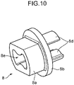
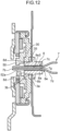
- the resin bush 8 in the modification has a pair of flat surfaces facing each other on a circumference of the main body 8a, as shown in Fig. 10 , Fig. 11C, and Fig. 11E .
- a rotation angle of each of the resin bush 8 and the connecting rod 7 is easily adjustable by using a tool.
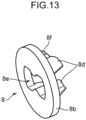
- a resin bush 8 may be configured to exclude a main body 8a and have an engagement part 8f engageable with a frame 3a.
- the engagement part 8f is configured to be engageable with the frame 3a of the seatback 3 that is fixedly attached to the internal gear 30, for example, has a claw engageable with an edge of the through hole 3b of the frame 3a.
- the engagement part 8f protrudes radially outward of the resin bush 8 from an outer surface 8d2 of each of a pair of claws 8d.
- the engagement part 8f of the resin bush 8 engages with the frame 3a (specifically, the edge of the through hole 3b) of the seatback 3 that is fixedly attached to the internal gear 30. This can prevent the resin bush 8 from coming off the frame 3a. Moreover, the resin bush 8 is firmly fixed by both the frame 3a and the internal gear 30. The resin bush 8 therefore can restrict the shift of the connecting rod 7 relative to the cam 50 in the radial direction of the cam 50. As a result, the effect of abnormal sound occurrence prevention is improved.
- the engagement part 8f may engage with the frame 2a of the seat cushion 2.
- each of the pair of claws 8d of the resin bush 8 has an outer surface 8d2 opposite to the connecting rod 7.
- the outer surface 8d2 has a taper shape slanting to the center of the bush insertion hole 35 as advancing to a leading end of the claw 8d to come into contact with the edge of the bush insertion hole 35 of the internal gear 30. The edge falls within the inner surface of the bush insertion hole 35.
- the pair of claws 8d of the resin bush 8 is placed in the bush insertion hole 35 in contact with the edge of the bush insertion hole 35, and thus can retain the connecting rod 7 at such a position to the cam 50 that the clearance 9 exists between the inner surface 52a1 of the rod insertion hole 52a of the cam 50 and the outer surface 7f of the connecting rod 7.
- the outer surface 8d2 having the taper shape in each of the claws 8d of the resin bush 8 comes into contact with the edge of the bush insertion hole 35 of the internal gear 30, thereby succeeding in reliably maintaining the contact state between the resin bush 8 and the internal gear 30.
- this configuration can accommodate a dimensional difference in one of the bush insertion hole 35 and the pair of claws 8d, or both the insertion hole and the claws.
- the taper section 7d is arranged in adjacent to the attachment position of the resin bush 8. This arrangement makes it possible to prevent the resin bush 8 from deviating in the axial direction and coming off (specifically, coming off the through hole 3b of the frame 3a and coming off the bush insertion hole 35 of the internal gear 30).
- a reclining device is a reclining device for holding a seatback to a seat cushion in a tiltable manner and fixing the seatback at a fixed tilt angle.
- the reclining device includes: a pair of reclining mechanisms arranged on both sides of a seat in a width direction thereof, and each having an internal gear fixedly attached to a frame of one of the seat cushion and the seatback and a cam arranged in juxtaposition with the internal gear in a thickness direction of the internal gear; a connecting rod extending in the width direction of the seat, coaxially coupled to the cam of each of the reclining mechanisms, and being rotatable together with the cam; and a resin bush having a cylindrical shape formed with a fit hole to receive a fitting part formed on the connecting rod at a portion adjacent to each end of the connecting rod.
- the cam has a rod insertion hole for allowing the end of the connecting rod to be inserted therein.
- the internal gear has a bush insertion hole for allowing the resin bush to be inserted therein at a center position of the internal gear.
- the fitting part adjacent to the end of the connecting rod fits in the fit hole of the resin bush, and the end of the connecting rod protrudes outward of the resin bush.
- the resin bush is placed in the bush insertion hole in contact with an inner surface of the bush insertion hole of the internal gear to retain the connecting rod at such a position to the cam that a clearance exists between an inner surface of the rod insertion hole of the cam and an outer surface of the connecting rod.
- the inner surface of the bush insertion hole has an edge of the bush insertion hole.
- the resin bush is placed in the bush insertion hole in contact with the inner surface of the bush insertion hole of the internal gear to retain the connecting rod at such a position to the cam that the clearance exists between the inner surface of the rod insertion hole of the cam and the outer surface of the connecting rod.
- the resin bush restricts the shift of the connecting rod relative to the cam in the radial direction of the cam, and thus can prevent an occurrence of a contact sound between the cam and the connecting rod. This results in achieving effective prevention of abnormal sound while permitting the clearance to exist between the inner surface of the rod insertion hole of the cam and the outer surface of the connecting rod.
- the fit hole of the resin bush preferably has a shape conforming to a contour of the fitting part of the connecting rod.
- a work of attaching the resin bush to the connecting rod is completed only by fitting the fitting part adjacent to the end of the connecting rod in the fit hole of the resin bush.
- the work has good workability.
- a simple configuration of the connecting rod and the resin bush in combination succeeds in preventing the resin bush from axially coming off the internal gear and further preventing the resin bush from falling off the connecting rod.
- the resin bush preferably has a flange coming into contact with the frame of the one of the seat cushion and the seatback that is fixedly attached to the internal gear in an axial direction of the connecting rod.
- the flange of the resin bush can restrict the shift of the resin bush in the axial direction of the connecting rod by coming into contact with the frame of the one of the seat cushion and the seatback in the axial direction.
- the resin bush preferably has a main body extending in the axial direction of the connecting rod and having a cylindrical shape to support the connecting rod in contact with an entire circumference of the connecting rod.
- the cylindrical main body of the resin bush supports the connecting rod in contact with the entire circumference of the connecting rod, and therefore can further restrict the shift of the connecting rod relative to the cam in the radial direction thereof. As a result, the effect of abnormal sound occurrence prevention is improved.
- the fitting part of the connecting rod preferably has a taper section narrowing as advancing to the end of the connecting rod
- the fit hole of the resin bush preferably has a taper hole section to fit to the taper section of the connecting rod.
- the taper section formed at the fitting part adjacent to the end of the connecting rod fits to the taper hole section of the fit hole of the resin bush to restrict the shift of the resin bush in the axial direction. Furthermore, a simple configuration of the connecting rod and the resin bush in combination succeeds in preventing the resin bush from axially coming off the internal gear and further preventing the resin bush from falling off the connecting rod without increasing the number of components.
- the resin bush preferably has a pair of claws extending in the axial direction of the connecting rod to support the connecting rod on both sides thereof.
- the claws of the resin bush support the connecting rod on both sides thereof, and therefore can further restrict the shift of the connecting rod relative to the cam in the radial direction. As a result, the effect of abnormal sound occurrence prevention is improved.
- the claws respectively have portions facing each other, and each having a shape fittable onto the fitting part of the connecting rod.
- each of the facing portions of the claws of the resin bush that face each other fit to the fitting part adjacent to the end of the connecting rod, and therefore can further restrict the shift of the connecting rod relative to the cam in the radial direction. As a result, the effect of abnormal sound occurrence prevention is improved.
- each of the claws preferably has an outer surface opposite to the connecting rod, and the outer surface preferably has a shape fittable in the bush insertion hole of the internal gear.
- the claws of the resin bush more effectively support the connecting rod on both sides thereof owing to the fitting of the pair of claws in the bush insertion hole of the internal gear.
- This enables further restriction of the shift of the connecting rod relative to the cam in the radial direction.
- the mere fitting of the pair of claws in the bush insertion hole facilitates determination on the positions of the resin bush and the connecting rod, resulting in improvement of the workability in the assembly of the reclining device.
- each of the claws preferably has an outer surface opposite to the connecting rod, and the outer surface preferably has a taper shape slanting to a center of the bush insertion hole as advancing to a leading end of the claw to come into contact with an edge of the bush insertion hole of the internal gear.
- the outer surface having the taper shape in each of the claws of the resin bush comes into contact with the edge of the bush insertion hole of the internal gear, thereby succeeding in reliably maintaining the contact state between the resin bush and the internal gear.
- this configuration can accommodate a dimensional difference in one of the bush insertion hole of the claws, or both the insertion hole and the claws.
- the resin bush further preferably has an engagement part engageable with the frame of the one of the seat cushion and the seatback that is fixedly attached with the internal gear.
- the engagement part of the resin bush can prevent the resin bush from coming off the frame of one of the seat cushion and the seatback that is fixedly connected to the internal gear by engaging with the frame. Moreover, the resin bush is firmly fixed by both the frame and the internal gear. The resin bush therefore can restrict the shift of the connecting rod relative to the cam in the radial direction of the cam. As a result, the effect of abnormal sound occurrence prevention is improved.
- a seat includes: a seat cushion: a seatback located in the rear of the seat cushion and being tiltable in a front-rear direction of the seat; and the reclining device to fixedly hold the seatback at a certain tilt angle.
- the seat includes the reclining device having the configuration where the resin bush is placed in the bush insertion hole in contact with the inner surface of the bush insertion hole of the internal gear to retain the connecting rod in the state where the clearance exists between the inner surface of the rod insertion hole of the cam and the outer surface of the connecting rod.
- the resin bush restricts the shift of the connecting rod relative to the cam in the radial direction of the cam. This results in achieving effective prevention of abnormal sound while permitting the clearance to exist between the inner surface of the rod insertion hole of the cam and the outer surface of the connecting rod.
- Each of the reclining device and the seat according to the embodiment achieves effective prevention of abnormal sound while permitting the clearance to exist between the inner surface of the rod insertion hole of the cam and the outer surface of the connecting rod.
Landscapes
- Engineering & Computer Science (AREA)
- Aviation & Aerospace Engineering (AREA)
- Transportation (AREA)
- Mechanical Engineering (AREA)
- Chairs For Special Purposes, Such As Reclining Chairs (AREA)
- Seats For Vehicles (AREA)
Abstract
Description
- The present invention relates to a reclining device, and a seat including the reclining device.
- Conventional seats for vehicles involve a seat which includes a reclining device for fixing a seatback or backrest at a certain tilt angle in such a manner that the seatback is tiltable to a seat cushion or seat base in a front-rear direction.
- The reclining device includes a pair of reclining mechanisms or recliners arranged on both sides of the seat in a width direction of the seat, and a connecting rod extending in the width direction of the seat and coupled to the reclining mechanisms.
- Each of the reclining mechanisms has a cam coaxially coupled to each of the opposite ends of the connecting rod and being rotatable together with the connecting rod. When the connecting rod receives a rotational manipulation force from the outside of the seat, the cam rotates together with the connecting rod in a predetermined direction to disconnect a locking plate arranged in the periphery of the cam from an internal gear, thereby achieving lock release.
- The structure where each end of the connecting rod is coaxially coupled to the cam, as described above, requires a clearance between an inner surface of a through hole of the cam and an outer surface of the connecting rod. Specifically, a dimensional difference and distortion of a frame assembly (i.e., an assembly including: frames of the seatback and the seat cushions; and the reclining mechanisms attached to the frames) that are attributed to deviation and twisting in setting up the frame assembly may give unfavorable influence on operability of the reclining mechanisms and a lock load. It is necessary to provide the clearance to accommodate the unfavorable influence.
- The conventional reclining device requiring the clearance between the cam and the connecting rod has drawbacks that the cam and the connecting rod interfere with each other due to bouncing or swaying of a vehicle body, or an impact from the outside, resulting in making an abnormal sound (hitting sound).
- In this regard, the reclining device disclosed in
Patent Literature 1 has a thin elastic ring interposed between the cam and the connecting rod to prevent an occurrence of an abnormal sound while permitting a clearance to exist between the cam and the connecting rod. In this manner, abnormal sound suppression is aimed. - However, in the structure having the thin elastic ring interposed between the cam and the connecting rod as described in
Patent Literature 1, the thin elastic ring determines relative positions of the cam and the connecting rod. For this reason, it is difficult to achieve effective prevention of abnormal sound while permitting the clearance to exist between the cam and the connecting rod. The reasons will be described below. - First, the elastic ring has a dimension restricted by a width of the clearance between the cam and the connecting rod. This makes it structurally difficult to increase the stiffness of the elastic ring by increasing the thickness of the elastic ring. Increasing the stiffness of the elastic ring for the prevention of abnormal sound under the dimensional restriction of the elastic ring leads to difficulty in inserting the elastic ring into the clearance between the cam and the connecting rod. This results in affecting the assembly of the reclining device. On the other hand, decreasing the stiffness of the elastic ring causes reduction in a holding force of the connecting rod, and thus an abnormal sound occurs even when the connecting rod only slightly shifts and comes into contact with the cam. From these perspectives, it is difficult to achieve effective prevention of abnormal sound while permitting the clearance to exist.
- Patent Literature 1:
Japanese Patent Publication Number 3972648 - The present invention has been achieved in view of the circumstances described above, and has an object of providing a reclining device that achieves effective prevention of abnormal sound while permitting a clearance to exist between a cam and a connecting rod.
- A reclining device according to the present invention is a reclining device for holding a seatback to a seat cushion in a tiltable manner and fixing the seatback at a certain tilt angle. The reclining device includes: a pair of reclining mechanisms arranged on both sides of a seat in a width direction thereof, and each having an internal gear fixedly attached to a frame of one of the seat cushion and the seatback and a cam arranged in juxtaposition with the internal gear in a thickness direction of the internal gear; a connecting rod extending in the width direction of the seat, coaxially coupled to the cam of each of the reclining mechanisms, and being rotatable together with the cam; and a resin bush having a cylindrical shape formed with a fit hole to receive a fitting part formed on the connecting rod at a portion adjacent to each end of the connecting rod. The cam has a rod insertion hole for allowing the end of the connecting rod to be inserted therein. The internal gear has a bush insertion hole for allowing the resin bush to be inserted therein at a center position of the internal gear. The fitting part adjacent to the end of the connecting rod fits in the fit hole of the resin bush, and the end of the connecting rod protrudes outward of the resin bush. The resin bush is placed in the bush insertion hole in contact with an inner surface of the bush insertion hole of the internal gear to retain the connecting rod at such a position to the cam that a clearance exists between an inner surface of the rod insertion hole of the cam and an outer surface of the connecting rod. The inner surface of the bush insertion hole has an edge of the bush insertion hole.
-
-
Fig. 1 is a perspective view showing an overall configuration of a seat including a reclining device according to an embodiment of the present invention. -
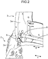
Fig. 2 is an enlarged perspective view showing arrangement of a resin bush and the reclining mechanism which are adjacent to each end of the connecting rod as shown inFig. 1 . -
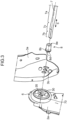
Fig. 3 is a perspective view showing a disassembled state of the connecting rod, the resin bush, and the reclining mechanism shown inFig. 2 . -
Fig. 4 is a perspective view of the resin bush shown inFig. 3 -
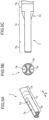
Fig. 5A to Fig.5C include views of the connecting rod shown inFig.3 , specifically,Fig. 5A being an enlarged perspective view showing a structure around the end of the connecting rod,Fig. 5B being a view of the end seen from a tip thereof shown inFig. 5A, and Fig. 5C showing a peripheral structure of the end shown inFig. 5A as seen from an outer circumference thereof. -
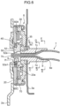
Fig. 6 is a cross-sectional explanatory view of a structure of a main portion of the reclining device shown inFig. 1 where the connecting rod, the resin bush, and the reclining mechanism as shown inFig. 2 are assembled together. -
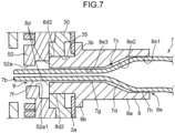
Fig. 7 is an enlarged cross-sectional view of the resin bush shown inFig. 6 and a periphery therearound. -
Fig. 8A to Fig.8E include cross-sectional views taken along respective lines about the connecting rod and the periphery therearound shown inFig. 6 , specifically,Fig. 8A being a cross-sectional view taken along the line A-A,Fig. 8B being a cross-sectional view taken along the line B-B,Fig. 8C being a cross sectional view taken along the line C-C,Fig. 8D being a cross-sectional view taken along the line D-D, andFig. 8E being a cross-sectional view taken along the line E-E. -
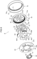
Fig. 9 is an exploded perspective view of the reclining mechanism shown inFig. 3 . -
Fig. 10 is a perspective view of the resin bush having an improved main body, according to a modification of the present invention. -
Fig. 11A to Fig. 11E include views of the resin bush shown inFig. 10 , specifically,Fig. 11A being a side view of the resin bush seen from a leading end of a claw,Fig. 11B being a front view of the resin bush,Fig. 11C being a side view thereof seen from a leading end of the main body,Fig. 11D being a cross-sectional view taken along the line F-F inFig. 11C, and Fig. 11E being a plan view. -
Fig. 12 is a cross-sectional explanatory view of a structure of the resin bush shown inFig. 10 , and the connecting rod and the reclining mechanism shown inFig. 6 , as assembled together. -
Fig. 13 is a perspective view of a small-type resin bush having an engagement part engageable with a frame, according to another modification of the present invention. -
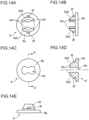
Fig. 14A to Fig. 14E include views of the resin bush shown inFig. 13 , specifically,Fig. 14A being a side view of the resin bush seen from a leading end of a claw,Fig. 14B being a front view of the resin bush,Fig. 11C being a side view seen in a direction of facing a flat surface of a flange,Fig. 14D being a cross-sectional view taken along the line G-G inFig. 14C, and Fig. 14E being a plan view. -
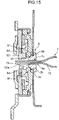
Fig. 15 is a cross-sectional explanatory view of a structure of the resin bush shown inFig. 13 , and the connecting rod and the reclining mechanism shown inFig. 6 , as assembled together. - Hereinafter, a preferable embodiment of the present invention will be described with reference to the accompanying drawings.
- As shown in
Fig. 1 , aseat 1 according to the embodiment is a vehicle seat, and includes: aseat cushion 2 for supporting buttocks of a seated person; aseatback 3 arranged in the rear of theseat cushion 2 to support the back of the seated person and being tiltable to theseat cushion 2 in a front-rear direction X of theseat 1; a slidingdevice 4 attached to a lower portion of theseat cushion 2; and areclining device 5. - The sliding
device 4 is configured to guide theseat cushion 2 slidably in the front-rear direction X of theseat 1, and fixedly hold theseat cushion 2 at a certain position. Here, the seat according to the present invention may not indispensably include the slidingdevice 4. - The
reclining device 5 is configured to fixedly hold theseatback 3 at a certain tilt angle. - Specifically, as shown in
Fig. 2 to Fig. 3 , thereclining device 5 according to the embodiment includes: a pair ofreclining mechanism 6; a connectingrod 7 connected to each of thereclining mechanisms 6; and a pair ofresin bushes 8 to each receive afitting part 7c at a portion adjacent to corresponding one ofends 7b of the connectingrod 7. - The
reclining mechanisms 6 are respectively arranged on both sides of theseat 1 in a width direction Y thereof. Each of thereclining mechanisms 6 serves as a clutch to fixedly hold theseatback 3 at a certain tilt angle. The configuration of the reclining mechanism will be described in detail later. - As shown in
Fig. 3 ,Fig. 6 , andFig. 9 , thereclining mechanism 6 in the embodiment includes: aninternal gear 30 fixedly attached to a frame of one of theseat cushion 2 and theseatback 3, that is, to aframe 3a of the seatback 3 (specifically, a side frame forming a side portion of the seatback 3) in the embodiment in a fitting or welding manner; and acam 50 arranged in juxtaposition with theinternal gear 30 in a thickness direction of the internal gear (i.e., in an axial direction S of the connectingrod 7 shown inFig. 3 ). - In other words, in the reclining device according to the present invention, the
reclining mechanism 6 may include at least theinternal gear 30 and thecam 50, and thus the remaining structural components may be appropriately changed. - As shown in
Fig. 6 to Fig. 7 ,Fig. 8A , andFig. 9 , thecam 50 has arod insertion hole 52a for allowing theend 7b of the connectingrod 7 to be inserted therein. Therod insertion hole 52a has a substantially elliptical shape, specifically, a circular shape inwardly narrowing from specific facing sides, in a cross section (in particular, seeFig. 8A andFig. 9 ). - As shown in
Fig. 6 to Fig. 7 , andFig. 9 , theinternal gear 30 has abush insertion hole 35 for allowing theresin bush 8 to be inserted therein through a throughhole 3b (seeFig. 3 , andFig. 6 toFig. 7 ) formed in theframe 3a at a center position of theinternal gear 30. Thebush insertion hole 35 has a cross-sectionally circular shape. - As shown in
Fig. 1 to Fig. 3 , the connectingrod 7 is a rod-shaped member extending in the width direction Y of theseat 1 and made of hard material, such as steel. - As shown in
Fig. 5A to Fig. 5C , the connectingrod 7 specifically has acenter part 7a having a cross-sectionally circular shape, the pair ofends 7b on both sides of thecenter part 7a, and the pair offitting parts 7c. - Each
end 7b has a shape approximate to a substantially elliptical shape conforming to the substantially elliptical shape of therod insertion hole 52a (seeFig. 8A andFig. 9 ) of thecam 50. Specifically, theend 7b has a pair ofrecesses 7e recessed radially inward at the radially opposite positions to face each other. - Owing to the insertion of the
end 7b of the connectingrod 7 into therod insertion hole 52a of thecam 50 that has the substantially elliptical shape, the connectingrod 7 is coaxially coupled to thecam 50 of each of the pair ofreclining mechanisms 6 and can rotate together with the cam 50 (seeFig. 6 ). - As shown in
Fig. 6 to Fig. 7 , andFig. 8A , aclearance 9 exists between an inner surface 52a1 of therod insertion hole 52a of thecam 50 and anouter surface 7f of theend 7b of the connectingrod 7 in a state where theend 7b of the connectingrod 7 is placed in therod insertion hole 52a of thecam 50, in the same manner as a conventional art. This configuration can accommodate an unfavorable influence attributed to a dimensional difference and distortion of the frame assembly on the operability of thereclining mechanism 6 and a lock load. - As shown in
Fig. 5A and Fig. 5C , thefitting part 7c of the connectingrod 7 fits to theresin bush 8 at a portion adjacent to theend 7b (i.e., adjacent to theend 7b at a position closer to thecenter part 7a or at a position between thecenter part 7a and theend 7b) on each side of thecenter part 7a. Thefitting part 7c has ataper section 7d narrowing as advancing to theend 7b of the connectingrod 7. - Specifically, the
fitting part 7c has a cross-sectionallycircular section 7h (seeFig. 7 andFig. 8E ) continuous to thecenter part 7a, a cross-sectionally substantiallyelliptical section 7g (seeFig. 7 andFig. 8C ) continuous to theend 7b, and thetaper section 7d (seeFig. 7 andFig. 8D ) connecting the cross-sectionallycircular section 7h and the cross-sectionally substantiallyelliptical section 7g to each other therebetween. The cross-sectionally substantiallyelliptical section 7g also has therecess 7e continuous from theend 7b (seeFig. 5A ,Fig. 8A to Fig. 8B ). - The
taper section 7d has such a cross-sectional shape as to gradually change from a circular shape near the cross-sectionallycircular section 7h to a substantially elliptical shape conforming to the shape of theend 7b as advancing to theend 7b. - The
resin bush 8 is made of resin material, and includes a cylindrical body having afit hole 8e, specifically, includes amain body 8a having a cylindrical shape, aflange 8b, and a pair ofclaws 8d as shown inFig. 4 . Themain body 8a, theflange 8b, and the pair ofclaws 8d are linearly assembled together in the axial direction S (seeFig. 3 ) of the connectingrod 7. - The
resin bush 8 is mainly made of resin material, such as plastic, to prevent an occurrence of an abnormal sound between the connectingrod 7 and thecam 50. The material for theresin bush 8 may be substituted by any material having elasticity, such as rubber (e.g., synthetic rubber) and elastomer. The material for theresin bush 8 may preferably have characteristics of low contact resistance between theinternal gear 30 and theframe 3a, and less abrasion. - The
resin bush 8 has thefit hole 8e to receive thefitting part 7c at a portion adjacent to theend 7b of the connectingrod 7. Thefit hole 8e axially penetrates themain body 8a and theflange 8b. - Therefore, as shown in
Fig. 6 to Fig. 7 andFig. 8C to Fig. 8E , the cylindricalmain body 8a extends in the axial direction S of the connectingrod 7 to support the connectingrod 7 in contact with an entire circumference of the connecting rod in the state where thefitting part 7c of the connectingrod 7 fits in thefit hole 8e of theresin bush 8. - The
fit hole 8e of theresin bush 8 has a shape conforming to a contour of thefitting part 7c of the connectingrod 7. Specifically, thefit hole 8e has a cross-sectionally circular hole section 8e1 (seeFig. 7 andFig. 8E ) conforming to the cross-sectionallycircular section 7h of thefitting part 7c, a taper hole section 8e2 (seeFig. 7 andFig. 8D ) conforming to thetaper section 7d, and a cross-sectionally substantially elliptical hole section 8e3 (seeFig. 7 andFig. 8C ) conforming to the cross-sectionally substantiallyelliptical section 7g. - The taper hole section 8e2 has a taper shape fittable onto the
taper section 7d of the connectingrod 7 that also has a taper shape. Although a small gap is seen between thetaper section 7d and an inner surface of the taper hole section 8e2 inFig. 7 andFig. 8D , the small gap may be excludable. - The
flange 8b of theresin bush 8 has a circular plate shape extending radially outward from an end periphery edge (specifically, outer end periphery edge in the axial direction S inFig. 3 ) of themain body 8a. Theflange 8b is contactable with theframe 3a (specifically, a surface of theframe 3a opposite to the internal gear 30) of theseatback 3 that is fixedly attached to theinternal gear 30 in the axial direction S of the connectingrod 7 in the state where theresin bush 8 is fitted to thefitting part 7c of the connecting rod 7 (seeFig. 3 , andFig. 6 toFig. 7 ). - As shown in
Fig. 4 ,Fig. 6 to Fig. 7 , andFig. 8B , the pair ofclaws 8d protrudes outward from a surface of theflange 8b opposite to themain body 8a and extends in the axial direction S of the connectingrod 7 to support the connectingrod 7 on both sides thereof. - As shown in
Fig. 8B , the twoclaws 8d respectively have facing portions 8d1 facing each other, each facing portion having a shape (e.g., a recessing or protruding shape) fittable onto the cross-sectionally substantiallyelliptical section 7g of thefitting part 7c of the connectingrod 7. Specifically, each of the facing portions 8d1 has a protruding shape fittable in the corresponding one of the pair ofrecesses 7e formed in the cross-sectionally substantiallyelliptical section 7g of thefitting part 7c. - Moreover, as shown in
Fig. 6 to Fig. 7 , each of theclaws 8d has an outer surface 8d2 opposite to the connectingrod 7, the outer surface having a shape fittable in thebush insertion hole 35 of theinternal gear 30. Specifically, as shown inFig. 8B , the outer surface 8d2 of each of theclaws 8d curves in an arc shape so that theclaws 8d are fittable in the bush insertion hole 35 (seeFig. 9 ) having a cross-sectionally circular shape. In other words, the outer surface 8d2 having the arc shape is in surface contact with the inner surface of thebush insertion hole 35 having the cross-sectionally circular shape in the state where theclaws 8d fit in thebush insertion hole 35. Consequently, a stable fitting state is attainable. - In the
reclining device 5 having the above-described configuration, first, theresin bush 8 is fitted to thefitting part 7c adjacent to theend 7b of the connectingrod 7 for coaxially coupling theend 7b of the connectingrod 7 to thereclining mechanism 6, as shown inFig. 2 to Fig. 3 , and -
Fig. 6 to Fig. 7 . At this time, theend 7b of the connectingrod 7 protrudes outward of theresin bush 8. - Next, the
end 7b of the connectingrod 7 and the pair ofclaws 8d of theresin bush 8 are inserted in thebush insertion hole 35 of theinternal gear 30 through the throughhole 3b of theframe 3a of theseatback 3. Specifically, the pair ofclaws 8d is fitted in thebush insertion hole 35 so that the outer surface 8d2 of each of theclaws 8d comes into contact with the inner surface and the edge of thebush insertion hole 35. At this time, theresin bush 8 is placed (specifically, fitted) in thebush insertion hole 35 of theinternal gear 30 to retain the connectingrod 7 at such a position to thecam 50 that theclearance 9 exists between the inner surface 52a1 of therod insertion hole 52a of thecam 50 and theouter surface 7f of theend 7b of the connectingrod 7. This allows theend 7b of the connectingrod 7 to fit in thebush insertion hole 35 of theinternal gear 30 while permitting theclearance 9 to exist. In the state where theresin bush 8 is placed (fitted) in thebush insertion hole 35, the outer surface 8d2 of each of theclaws 8d may be in contact with at least a part of the inner surface of thebush insertion hole 35, and may not be necessarily in contact with the edge of the inner surface of thebush insertion hole 35. - In this configuration, the
resin bush 8 is rotatable together with the connectingrod 7 and thecam 50 in the state where the pair ofclaws 8d fits in thebush insertion hole 35 of theinternal gear 30. - Hereinafter, a detailed configuration of the
reclining mechanism 6 in the embodiment will be described. As described above, thereclining mechanism 6 may include at least theinternal gear 30 and thecam 50 in the present invention. Hence, the remaining structural components may be appropriately changed. - The
reclining mechanism 6 is provided between aframe 2a of theseat cushion 2 and theframe 3a of the seatback 3 (seeFig. 2 to Fig. 3 ). - As shown in
Fig. 9 , thereclining mechanism 6 includes aguide bracket 20, theinternal gear 30, aspiral spring 40, thecam 50, fourlocking plates 60A to 60D, and anattachment ring 70. - As shown in
Fig. 3 andFig. 6 , theguide bracket 20 is fixed around the rear of theframe 2a (specifically, a side frame) of theseat cushion 2. Theinternal gear 30 is fixed around a lower portion of theframe 3a (specifically, a side frame) of theseatback 3. - In an arrangement of the
frame 2a of theseat cushion 2 inside theframe 3a of theseatback 3 as shown inFig. 3 , theinternal gear 30 may be fixedly attached to theframe 2a of theseat cushion 2, and theguide bracket 20 may be fixedly attached to theframe 3a of theseatback 3. - As shown in
Fig. 9 , theguide bracket 20 has a disc shape, and has anarrangement hole 22 penetrating therethrough at a center thereof for arrangement of thespiral spring 40 therein. An inner surface of thearrangement hole 22 is formed with anengagement groove 22a. Theengagement groove 22a is engaged with anouter end 41 of thespiral spring 40. - The
internal gear 30 has a circular shape in a plan view and further has a cross-sectionally substantially recess shape. The internal gear includes arecess section 31 having an inner surface formed withinner teeth 32. Therecess section 31 faces aninner surface 20a (seeFig. 6 ) of theguide bracket 20. Theinternal gear 30 is coupled to, for example, theframe 3a of theseatback 3 via aconnection protrusion 34 protruding in a right depth direction on the paper ofFig. 9 . - The
guide bracket 20 and theinternal gear 30 are retained by theattachment ring 70 at such positions that theguide bracket 20 faces therecess section 31 of theinternal gear 30 and an end surface 31a1 of aperipheral wall 31a of therecess section 31 comes into contact with a surface of theguide bracket 20. - The
attachment ring 70 has anannular bottom plate 71 having an annular shape with a predetermined width in a substantially circle, and anannular side plate 72 extending in a direction substantially perpendicularly intersecting the outer edge of theannular bottom plate 71, that is, extending along anouter surface 31 a2 of theperipheral wall 31a of theinternal gear 30. In other words, theattachment ring 70 has a substantially L-shape defined by theannular bottom plate 71 and theannular side plate 72 in a radial cross-section. - In the embodiment, the
attachment ring 70 covers theguide bracket 20 and theinternal gear 30 in such a manner that anend edge 72a of theannular side plate 72 extends over the outer surface 31a2 of theperipheral wall 31a of theinternal gear 30 to reach anouter surface 21b of the guide bracket located beyond the outer surface 31a2 (on the left front side of paper ofFig. 9 ) in a state where theguide bracket 20 and therecess section 31 of theinternal gear 30 face each other to define an inner space therebetween for accommodating thespiral spring 40, thecam 50, and the lock mechanism including thelocking plates 60A to 60D therein. In this assembling manner, a central protrusion of theinternal gear 30 is exposed outward farther than an inner circle of the annular bottom plate 71 (exposed in the right depth direction on the paper ofFig. 9 ). After the attachment of theattachment ring 70 in this way, a portion of theannular side plate 72 that faces theouter surface 21b of theguide bracket 20 is fixedly welded to theouter surface 21b. Hence, theguide bracket 20 and theinternal gear 30 rotate relative to each other, when theseatback 3 is rotated relative to theseat cushion 2 in a state where theguide bracket 20 is fixedly attached to, for example, theframe 2a of theseat cushion 2 and theconnection protrusion 34 of theinternal gear 30 is fixedly attached to, for example, theframe 3a of theseatback 3. Theattachment ring 70 rotates together with theguide bracket 20 relative to theinternal gear 30. Theannular side plate 72 of theattachment ring 70 restricts a radial shift of theinternal gear 30. Theannular bottom plate 71 of the attachment ring restricts an axial shift of theinternal gear 30. - The
cam 50 is a member for reciprocally moving thelocking plates 60A to 60D in a radial direction of thecam 50. Thecam 50 is provided with four engagingprotrusions locking plates 60A to 60D at equal intervals in a circumferential direction, each engaging protrusion having a horn-like shape extending in a substantially arc. Amain body 52 of thecam 50, from which the engagingprotrusions 51, 51are excluded, is provided with fourbulges protrusions cam 50 is integrally fixed to a surface of aspacer 55, and has therod insertion hole 52a penetrating the center of thecam 50 to receive theend 7b of the connectingrod 7 inserted therein. When a manipulation member (not shown) attached to theend 7b of the connectingrod 7 is used to rotate the connectingrod 7 forward or backward, thecam 50 rotates in the same direction by following the connecting rod. - The
cam 50 has afirst shaft 53 protruding from a periphery of therod insertion hole 52a toward theguide bracket 20 on a surface facing theguide bracket 20. Thefirst shaft 53 has an outer diameter smaller than an inner diameter of thespiral spring 40, and thefirst shaft 53 is formed with anengagement slit 53a notched from an outer surface of the shaft toward a center thereof. Thespiral spring 40 is arranged to surround thefirst shaft 53, and has aninner end 42 engageable with the engagement slit 53a of the first shaft 53 (seeFig. 8A ) so as to be placed in thearrangement hole 22 of theguide bracket 20 together with thefirst shaft 53. Thespiral spring 40 urges thecam 50 in one rotational direction due to the engagement of theouter end 41 with theengagement groove 22a on the inner surface of thearrangement hole 22 of theguide bracket 20. - The
internal gear 30 is provided with asecond shaft 36 protruding toward thecam 50 at the center of the internal gear. Thesecond shaft 36 is inserted in a bearing hole (not shown) formed in thecam 50 to rotatably support thecam 50. - The four
locking plates 60A to 60D are used in the embodiment. The fourlocking plates 60A to 60D are respectively arranged to meet the four engagingprotrusions cam 50. Each of thelocking plates 60A to 60D is slidable in a radial direction of theguide bracket 20 along a guide groove (not shown) formed in theguide bracket 20 and extending in the radial direction thereof. - Concerning the
locking plates 60A to 60D and thecam 50, thelocking plates 60A to 60D are urged radially outward in response to a one-directional rotation of thecam 50 attributed to the elasticity of thespiral spring 40, and thelocking plates 60A to 60D shift toward the center in response to a reverse-directional rotation of thecam 50 by the connectingrod 7. Each of thelocking plates 60A to 60D has a substantially rectangular shape in a plan view. Thelocking plates 60A to 60D respectively have engagedgrooves cam 50 rotates in a clockwise direction, the engagingprotrusions grooves locking plates 60A to 60D toward the center of thecam 50. When thecam 50 is urged by thespiral spring 40 and rotates in a counter-clockwise direction, the engagingprotrusions bulges locking plates 60A to 60D radially outward of thecam 50. Thelocking plates 60A to 60D have outer surfaces respectively formed withouter teeth inner teeth 32 of theinternal gear 30 when the plates are pressed radially outward, thereby locking theguide bracket 20 and theinternal gear 30 irrotationally relative to each other. This achieves fixed holding of theseatback 3 at a certain tilt angle. -
- (1) The
reclining device 5 according to the embodiment fixedly holds theseatback 3 shown inFig. 1 to theseat cushion 2 in a tiltable manner and fixes the seatback at a certain tilt angle. - As shown in
Fig. 1 to Fig. 6 , thereclining device 5 includes: the pair ofreclining mechanisms 6 arranged on both sides of theseat 1 in the width direction Y thereof, and each having theinternal gear 30 fixedly attached to the frame of one of theseat cushion 2 and the seatback 3 (to theframe 3a of theseatback 3 in the embodiment), and thecam 50 arranged in juxtaposition with theinternal gear 30 in the thickness direction (i.e., width direction Y) of the internal gear; and the connectingrod 7 extending in the width direction Y of theseat 1, coaxially coupled to thecam 50 of each of thereclining mechanisms 6, and being rotatable together with thecam 50. - The
reclining device 5 according to the embodiment further includes theresin bush 8 having a cylindrical shape formed with thefit hole 8e to receive thefitting part 7c at a portion adjacent to eachend 7b of the connectingrod 7. - As shown in
Fig. 6 to Fig. 7 , thecam 50 has therod insertion hole 52a for allowing theend 7b of the connectingrod 7 to be inserted therein. Theinternal gear 30 has thebush insertion hole 35 for allowing theresin bush 8 to be inserted therein at the center position of theinternal gear 30. - As shown in
Fig. 6 to Fig. 7 , andFig. 8A , thefitting part 7c adjacent to theend 7b of the connectingrod 7 fits in thefit hole 8e of theresin bush 8, and theend 7b of the connectingrod 7 protrudes outward of theresin bush 8. Theresin bush 8 is placed in thebush insertion hole 35 in contact with the inner surface of thebush insertion hole 35 of theinternal gear 30 to retain the connectingrod 7 at such a position to thecam 50 that theclearance 9 exists between the inner surface 52a1 of therod insertion hole 52a of thecam 50 and theouter surface 7f of the connectingrod 7. - According to this configuration, the
resin bush 8 is placed in thebush insertion hole 35 in contact with the inner surface of thebush insertion hole 35 of theinternal gear 30 to retain the connectingrod 7 at such a position to thecam 50 that theclearance 9 exists between the inner surface 52a1 of therod insertion hole 52a of thecam 50 and theouter surface 7f of the connectingrod 7. In this manner, theresin bush 8 restricts the shift of the connectingrod 7 relative to thecam 50 in the radial direction of thecam 50, and thus can prevent an occurrence of a contact sound between thecam 50 and the connectingrod 7. This results in achieving effective prevention of abnormal sound while permitting theclearance 9 to exist between the inner surface 52a1 of therod insertion hole 52a of thecam 50 and theouter surface 7f of the connectingrod 7. - Besides, the
resin bush 8 is not designed to determine relative positions of thecam 50 and the connectingrod 7 by intervening therebetween, but is designed to retain the connectingrod 7 at a specific position in a state of being placed in thebush insertion hole 35 of theinternal gear 30. Therefore, theresin bush 8 receives no dimensional restriction due to theclearance 9 between thecam 50 and the connectingrod 7 and no stiffness restriction based on such dimensional restriction. In this respect, theresin bush 8 can be set to a dimension and stiffness leading to less abrasion than those of the elastic ring of the conventional art (structure described in Patent Literature 1). - (2) In the
reclining device 5 according to the embodiment, thefit hole 8e of theresin bush 8 has a shape conforming to the contour of thefitting part 7c of the connectingrod 7. Specifically, as shown inFig. 7 andFig. 8C to Fig. 8E , thefit hole 8e has the cross-sectionally circular hole section 8e1, the taper hole section 8e2, and the cross-sectionally substantially elliptical hole section 8e3. - According to this configuration, a work of attaching the
resin bush 8 to thefitting part 7c at a portion of the connectingrod 7 adjacent to theend 7b is completed only by fitting thefitting part 7c adjacent to theend 7b of the connectingrod 7 in thefit hole 8e of theresin bush 8. Thus the work has good workability. Furthermore, a simple configuration of the connectingrod 7 and theresin bush 8 in combination succeeds in preventing theresin bush 8 from axially coming off theinternal gear 30 and further preventing theresin bush 8 from falling off the connectingrod 7. - (3) In the
reclining device 5 according to the embodiment, as shown inFig. 3 to Fig. 4 andFig. 6 to Fig. 7 , theresin bush 8 has theflange 8b coming into contact with theframe 3a of theseatback 3, which is fixedly attached to theinternal gear 30, in the axial direction S of the connectingrod 7. - According to this configuration, the
flange 8b of theresin bush 8 can restrict the shift of theresin bush 8 in the axial direction S by coming into contact with theframe 3a of theseatback 3 in the axial direction S of the connectingrod 7. - Moreover, the
flange 8b can prevent an unacceptable matter from entering thereclining mechanism 6 through the throughhole 3b by closing a gap between theresin bush 8 and an inner surface of the throughhole 3b of theframe 3a. - (4) In the
reclining device 5 according to the embodiment, theresin bush 8 has themain body 8a extending in the axial direction S of the connectingrod 7 and having a cylindrical shape to support the connectingrod 7 in contact with an entire circumference of the connecting rod. - According to this configuration, the cylindrical
main body 8a of theresin bush 8 supports the connectingrod 7 in contact with the entire circumference of the connecting rod, and therefore can further restrict the shit of the connectingrod 7 relative to thecam 50 in the radial direction thereof. As a result, the effect of abnormal sound occurrence prevention is improved. - (5) In the
reclining device 5 according to the embodiment, as shown inFig. 5 to Fig. 7 , thefitting part 7c of the connectingrod 7 has thetaper section 7d narrowing as advancing to theend 7b of the connectingrod 7. As shown inFig. 7 andFig. 8D , thefit hole 8e of theresin bush 8 has the taper hole section 8e2 fittable to thetaper section 7d of the connectingrod 7. - According to this configuration, the
taper section 7d formed at thefitting part 7c adjacent to theend 7b of the connectingrod 7 fits to the taper hole section 8e2 of thefit hole 8e of theresin bush 8 to restrict the shift of theresin bush 8 in the axial direction. Furthermore, a simple configuration of the connectingrod 7 and theresin bush 8 in combination succeeds in preventing theresin bush 8 from axially coming off theinternal gear 30 and further preventing theresin bush 8 from falling off the connectingrod 7 without increasing the number of components. - (6) In the
reclining device 5 according to the embodiment, as shown inFig. 4 ,Fig. 6 to Fig. 7 , andFig. 8B , theresin bush 8 has the pair ofclaws 8d extending in the axial direction S of the connectingrod 7 to support the connectingrod 7 on both sides thereof. - According to this configuration, the
claws 8d of theresin bush 8 support the connectingrod 7 on both sides thereof, and therefore can further restrict the shift of the connectingrod 7 relative to thecam 50 in the radial direction. As a result, the effect of abnormal sound occurrence prevention is improved. - (7) In the
reclining device 5 according to the embodiment, as shown inFig. 8B , each of the facing portions 8d1 of theclaws 8d facing each other has a shape fittable onto thefitting part 7c of the connectingrod 7. Specifically, each of the facing portions 8d1 has a protruding shape fittable in thecorresponding recess 7e in the cross-sectionally substantiallyelliptical section 7g of thefitting part 7c. - According to this configuration, each of the facing portions 8d1 of the
claws 8d of theresin bush 8 that face each other fit to thefitting part 7c adjacent to theend 7b of the connectingrod 7, and therefore can further restrict the shift of the connectingrod 7 relative to thecam 50 in the radial direction. As a result, the effect of abnormal sound occurrence prevention is improved. - (8) In the
reclining device 5 according to the embodiment, as shown inFig. 6 to Fig. 7 andFig. 8B , each of theclaws 8d has the outer surface 8d2 opposite to the connectingrod 7. The outer surface 8d2 of each of the twoclaws 8d has a shape fittable in thebush insertion hole 35 of theinternal gear 30. In other words, the outer surface 8d2 of eachclaw 8d has an arc shape fittable in thebush insertion hole 35 having the cross-sectionally circular shape. - According to this configuration, the pair of
claws 8d of theresin bush 8 can more effectively support the connectingrod 7 on both sides thereof owing to fitting of the pair ofclaws 8d in thebush insertion hole 35 of theinternal gear 30. This enables further restriction of the shift of the connectingrod 7 relative to thecam 50 in the radial direction. In addition, the mere fitting of the pair ofclaws 8d in thebush insertion hole 35 facilitates determination on the positions of theresin bush 8 and the connectingrod 7, resulting in improvement of the workability in the assembly of thereclining device 5. - (9) As shown in
Fig. 1 to Fig. 7 , theseat 1 according to the embodiment includes: theseat cushion 2; theseatback 3 arranged in the rear of theseat cushion 2 and being tiltable in the front-rear direction X of theseat 1; and thereclining device 5 having the above-described configuration for fixedly holding theseatback 3 at a certain tilt angle. - The
seat 1 includes thereclining device 5 having the configuration where theresin bush 8 is placed in thebush insertion hole 35 in contact with the inner surface of thebush insertion hole 35 of theinternal gear 30 to retain the connectingrod 7 in the state where theclearance 9 exists between the inner surface 52a1 of therod insertion hole 52a of thecam 50 and theouter surface 7f of the connectingrod 7. In this manner, theresin bush 8 restricts the shift of the connectingrod 7 relative to thecam 50 in the radial direction of thecam 50. This results in achieving effective prevention of abnormal sound while permitting theclearance 9 to exist between the inner surface 52a1 of therod insertion hole 52a of thecam 50 and theouter surface 7f of the connectingrod 7. - As shown in
Fig. 4 andFig. 7 , themain body 8a of theresin bush 8 in the embodiment has such a length as to be fittable to the entirety of thefitting part 7c of the connectingrod 7, i.e., to be fittable to the cross-sectionallycircular section 7h and thetaper section 7d in addition to the cross-sectionally substantiallyelliptical section 7g. However, in the present invention, the length of themain body 8a of theresin bush 8 is not particularly limited. - Therefore, in a modification of the present invention as shown in
Fig. 10 to Fig. 12 , the length of amain body 8a of aresin bush 8 may be changed to be fittable only to a cross-sectionally substantiallyelliptical section 7g. - In the modification shown in
Fig. 10 to Fig. 12 , downsizing of theresin bush 8 is attainable by decreasing the length of themain body 8a. - Even in the modification shown in
Fig. 10 to Fig. 12 , the cross-sectionally substantiallyelliptical section 7g (i.e., the section having therecess 7e shown inFig. 8B to Fig. 8C ) of the connectingrod 7 can restrict the shift of the connectingrod 7 relative to thecam 50 in a radial direction thereof by fitting in thefit hole 8e (specifically, the cross-sectionally substantially elliptical hole section 8e3 as shown inFig. 8C ) of themain body 8a of theresin bush 8 and fitting to the protruding facing portions 8d1 of the pair ofclaws 8d. As a result, the effect of abnormal sound occurrence prevention is improved. - In the modification, as shown in
Fig. 12 , although theresin bush 8 is not fitted to thetaper section 7d of the connectingrod 7, thetaper section 7d is arranged in adjacent to the attachment position of theresin bush 8. This arrangement makes it possible to prevent theresin bush 8 from deviating in the axial direction and coming off (specifically, coming off the throughhole 3b of theframe 3a and coming off thebush insertion hole 35 of the internal gear 30). - The
resin bush 8 in the modification has a pair of flat surfaces facing each other on a circumference of themain body 8a, as shown inFig. 10 ,Fig. 11C, and Fig. 11E . Thus, a rotation angle of each of theresin bush 8 and the connectingrod 7 is easily adjustable by using a tool. - In another modification of the present invention as shown in
Fig. 13 to Fig. 15 , aresin bush 8 may be configured to exclude amain body 8a and have anengagement part 8f engageable with aframe 3a. - The
engagement part 8f is configured to be engageable with theframe 3a of theseatback 3 that is fixedly attached to theinternal gear 30, for example, has a claw engageable with an edge of the throughhole 3b of theframe 3a. Theengagement part 8f protrudes radially outward of theresin bush 8 from an outer surface 8d2 of each of a pair ofclaws 8d. - In the modification in
Fig. 13 to Fig. 15 , theengagement part 8f of theresin bush 8 engages with theframe 3a (specifically, the edge of the throughhole 3b) of theseatback 3 that is fixedly attached to theinternal gear 30. This can prevent theresin bush 8 from coming off theframe 3a. Moreover, theresin bush 8 is firmly fixed by both theframe 3a and theinternal gear 30. Theresin bush 8 therefore can restrict the shift of the connectingrod 7 relative to thecam 50 in the radial direction of thecam 50. As a result, the effect of abnormal sound occurrence prevention is improved. - In a case where the
internal gear 30 is fixedly attached to theframe 2a of theseat cushion 2, theengagement part 8f may engage with theframe 2a of theseat cushion 2. - In the modification shown in
Fig. 13 to Fig. 15 , each of the pair ofclaws 8d of theresin bush 8 has an outer surface 8d2 opposite to the connectingrod 7. The outer surface 8d2 has a taper shape slanting to the center of thebush insertion hole 35 as advancing to a leading end of theclaw 8d to come into contact with the edge of thebush insertion hole 35 of theinternal gear 30. The edge falls within the inner surface of thebush insertion hole 35. In this configuration, the pair ofclaws 8d of theresin bush 8 is placed in thebush insertion hole 35 in contact with the edge of thebush insertion hole 35, and thus can retain the connectingrod 7 at such a position to thecam 50 that theclearance 9 exists between the inner surface 52a1 of therod insertion hole 52a of thecam 50 and theouter surface 7f of the connectingrod 7. - According to this configuration, the outer surface 8d2 having the taper shape in each of the
claws 8d of theresin bush 8 comes into contact with the edge of thebush insertion hole 35 of theinternal gear 30, thereby succeeding in reliably maintaining the contact state between theresin bush 8 and theinternal gear 30. Moreover, this configuration can accommodate a dimensional difference in one of thebush insertion hole 35 and the pair ofclaws 8d, or both the insertion hole and the claws. - In the modification shown in
Fig. 13 to Fig. 15 , downsizing of theresin bush 8 is attainable by excluding themain body 8a. - Furthermore, as shown in
Fig. 15 , although theresin bush 8 is not fitted to thetaper section 7d of the connectingrod 7, thetaper section 7d is arranged in adjacent to the attachment position of theresin bush 8. This arrangement makes it possible to prevent theresin bush 8 from deviating in the axial direction and coming off (specifically, coming off the throughhole 3b of theframe 3a and coming off thebush insertion hole 35 of the internal gear 30). - The embodiment is summarized in the following manner.
- A reclining device according to the embodiment is a reclining device for holding a seatback to a seat cushion in a tiltable manner and fixing the seatback at a fixed tilt angle. The reclining device includes: a pair of reclining mechanisms arranged on both sides of a seat in a width direction thereof, and each having an internal gear fixedly attached to a frame of one of the seat cushion and the seatback and a cam arranged in juxtaposition with the internal gear in a thickness direction of the internal gear; a connecting rod extending in the width direction of the seat, coaxially coupled to the cam of each of the reclining mechanisms, and being rotatable together with the cam; and a resin bush having a cylindrical shape formed with a fit hole to receive a fitting part formed on the connecting rod at a portion adjacent to each end of the connecting rod. The cam has a rod insertion hole for allowing the end of the connecting rod to be inserted therein. The internal gear has a bush insertion hole for allowing the resin bush to be inserted therein at a center position of the internal gear. The fitting part adjacent to the end of the connecting rod fits in the fit hole of the resin bush, and the end of the connecting rod protrudes outward of the resin bush. The resin bush is placed in the bush insertion hole in contact with an inner surface of the bush insertion hole of the internal gear to retain the connecting rod at such a position to the cam that a clearance exists between an inner surface of the rod insertion hole of the cam and an outer surface of the connecting rod. The inner surface of the bush insertion hole has an edge of the bush insertion hole.
- According this configuration, the resin bush is placed in the bush insertion hole in contact with the inner surface of the bush insertion hole of the internal gear to retain the connecting rod at such a position to the cam that the clearance exists between the inner surface of the rod insertion hole of the cam and the outer surface of the connecting rod. In this manner, the resin bush restricts the shift of the connecting rod relative to the cam in the radial direction of the cam, and thus can prevent an occurrence of a contact sound between the cam and the connecting rod. This results in achieving effective prevention of abnormal sound while permitting the clearance to exist between the inner surface of the rod insertion hole of the cam and the outer surface of the connecting rod.
- In the reclining device, the fit hole of the resin bush preferably has a shape conforming to a contour of the fitting part of the connecting rod.
- According to this configuration, a work of attaching the resin bush to the connecting rod is completed only by fitting the fitting part adjacent to the end of the connecting rod in the fit hole of the resin bush. Thus, the work has good workability. Furthermore, a simple configuration of the connecting rod and the resin bush in combination succeeds in preventing the resin bush from axially coming off the internal gear and further preventing the resin bush from falling off the connecting rod.
- In the reclining device, the resin bush preferably has a flange coming into contact with the frame of the one of the seat cushion and the seatback that is fixedly attached to the internal gear in an axial direction of the connecting rod.
- According to this configuration, the flange of the resin bush can restrict the shift of the resin bush in the axial direction of the connecting rod by coming into contact with the frame of the one of the seat cushion and the seatback in the axial direction.
- In the reclining device, the resin bush preferably has a main body extending in the axial direction of the connecting rod and having a cylindrical shape to support the connecting rod in contact with an entire circumference of the connecting rod.
- According to this configuration, the cylindrical main body of the resin bush supports the connecting rod in contact with the entire circumference of the connecting rod, and therefore can further restrict the shift of the connecting rod relative to the cam in the radial direction thereof. As a result, the effect of abnormal sound occurrence prevention is improved.
- In the reclining device, the fitting part of the connecting rod preferably has a taper section narrowing as advancing to the end of the connecting rod, and the fit hole of the resin bush preferably has a taper hole section to fit to the taper section of the connecting rod.
- According to this configuration, the taper section formed at the fitting part adjacent to the end of the connecting rod fits to the taper hole section of the fit hole of the resin bush to restrict the shift of the resin bush in the axial direction. Furthermore, a simple configuration of the connecting rod and the resin bush in combination succeeds in preventing the resin bush from axially coming off the internal gear and further preventing the resin bush from falling off the connecting rod without increasing the number of components.
- In the reclining device, the resin bush preferably has a pair of claws extending in the axial direction of the connecting rod to support the connecting rod on both sides thereof.
- According to this configuration, the claws of the resin bush support the connecting rod on both sides thereof, and therefore can further restrict the shift of the connecting rod relative to the cam in the radial direction. As a result, the effect of abnormal sound occurrence prevention is improved.
- In the reclining device, preferably, the claws respectively have portions facing each other, and each having a shape fittable onto the fitting part of the connecting rod.
- According to this configuration, each of the facing portions of the claws of the resin bush that face each other fit to the fitting part adjacent to the end of the connecting rod, and therefore can further restrict the shift of the connecting rod relative to the cam in the radial direction. As a result, the effect of abnormal sound occurrence prevention is improved.
- In the reclining device, each of the claws preferably has an outer surface opposite to the connecting rod, and the outer surface preferably has a shape fittable in the bush insertion hole of the internal gear.
- According to this configuration, the claws of the resin bush more effectively support the connecting rod on both sides thereof owing to the fitting of the pair of claws in the bush insertion hole of the internal gear. This enables further restriction of the shift of the connecting rod relative to the cam in the radial direction. In addition, the mere fitting of the pair of claws in the bush insertion hole facilitates determination on the positions of the resin bush and the connecting rod, resulting in improvement of the workability in the assembly of the reclining device.
- In the reclining device, each of the claws preferably has an outer surface opposite to the connecting rod, and the outer surface preferably has a taper shape slanting to a center of the bush insertion hole as advancing to a leading end of the claw to come into contact with an edge of the bush insertion hole of the internal gear.
- According to this configuration, the outer surface having the taper shape in each of the claws of the resin bush comes into contact with the edge of the bush insertion hole of the internal gear, thereby succeeding in reliably maintaining the contact state between the resin bush and the internal gear. Moreover, this configuration can accommodate a dimensional difference in one of the bush insertion hole of the claws, or both the insertion hole and the claws.
- In the reclining device, the resin bush further preferably has an engagement part engageable with the frame of the one of the seat cushion and the seatback that is fixedly attached with the internal gear.
- According to this configuration, the engagement part of the resin bush can prevent the resin bush from coming off the frame of one of the seat cushion and the seatback that is fixedly connected to the internal gear by engaging with the frame. Moreover, the resin bush is firmly fixed by both the frame and the internal gear. The resin bush therefore can restrict the shift of the connecting rod relative to the cam in the radial direction of the cam. As a result, the effect of abnormal sound occurrence prevention is improved.
- A seat according to the embodiment includes: a seat cushion: a seatback located in the rear of the seat cushion and being tiltable in a front-rear direction of the seat; and the reclining device to fixedly hold the seatback at a certain tilt angle.
- The seat includes the reclining device having the configuration where the resin bush is placed in the bush insertion hole in contact with the inner surface of the bush insertion hole of the internal gear to retain the connecting rod in the state where the clearance exists between the inner surface of the rod insertion hole of the cam and the outer surface of the connecting rod. In this manner, the resin bush restricts the shift of the connecting rod relative to the cam in the radial direction of the cam. This results in achieving effective prevention of abnormal sound while permitting the clearance to exist between the inner surface of the rod insertion hole of the cam and the outer surface of the connecting rod.
- Each of the reclining device and the seat according to the embodiment achieves effective prevention of abnormal sound while permitting the clearance to exist between the inner surface of the rod insertion hole of the cam and the outer surface of the connecting rod.
Claims (11)
- A reclining device for holding a seatback to a seat cushion in a tiltable manner and fixing the seatback at a certain tilt angle, the reclining device comprising:a pair of reclining mechanisms arranged on both sides of a seat in a width direction thereof, and each having an internal gear fixedly attached to a frame of one of the seat cushion and the seatback and a cam arranged in juxtaposition with the internal gear in a thickness direction of the internal gear;a connecting rod extending in the width direction of the seat, coaxially coupled to the cam of each of the reclining mechanisms, and being rotatable together with the cam; anda resin bush having a cylindrical shape formed with a fit hole to receive a fitting part formed on the connecting rod at a portion adjacent to each end of the connecting rod, whereinthe cam has a rod insertion hole for allowing the end of the connecting rod to be inserted therein,the internal gear has a bush insertion hole for allowing the resin bush to be inserted therein at a center position of the internal gear,the fitting part adjacent to the end of the connecting rod fits in the fit hole of the resin bush, and the end of the connecting rod protrudes outward of the resin bush, andthe resin bush is placed in the bush insertion hole in contact with an inner surface of the bush insertion hole of the internal gear to retain the connecting rod at such a position to the cam that a clearance exists between an inner surface of the rod insertion hole of the cam and an outer surface of the connecting rod.
- The reclining device according to claim 1, wherein the fit hole of the resin bush has a shape conforming to a contour of the fitting part of the connecting rod.
- The reclining device according to claim 1 or 2, wherein the resin bush has a flange coming into contact with the frame of the one of the seat cushion and the seatback that is fixedly attached to the internal gear in an axial direction of the connecting rod.
- The reclining device according to any one of claims 1 to 3, wherein the resin bush has a main body extending in the axial direction of the connecting rod and having a cylindrical shape to support the connecting rod in contact with an entire circumference of the connecting rod.
- The reclining device according to any one of claims 1 to 4, wherein the fitting part of the connecting rod has a taper section narrowing as advancing to the end of the connecting rod, and the fit hole of the resin bush has a taper hole section to fit to the taper section of the connecting rod.
- The reclining device according to any one of claims 1 to 5, wherein the resin bush has a pair of claws extending in the axial direction of the connecting rod to support the connecting rod on both sides thereof.
- The reclining device according to claim 6, wherein the claws respectively have portions facing each other, and each having a shape fittable onto the fitting part of the connecting rod.
- The reclining device according to claim 6 or 7, wherein each of the claws has an outer surface opposite to the connecting rod, and
the outer surface has a shape fittable in the bush insertion hole of the internal gear. - The reclining device according to claim 6 or 7, wherein each of the claws has an outer surface opposite to the connecting rod, and
the outer surface has a taper shape slanting to a center of the bush insertion hole as advancing to a leading end of the claw to come into contact with an edge of the bush insertion hole of the internal gear. - The reclining device according to any one of claims 1 to 9, wherein the resin bush further has an engagement part engageable with the frame of the one of the seat cushion and the seatback that is fixedly attached to the internal gear.
- A seat comprising:
a seat cushion:a seatback located in the rear of the seat cushion and being tiltable in a front-rear direction of the seat; andthe reclining device according to claim 1 to fixedly hold the seatback at a certain tilt angle.
Applications Claiming Priority (2)
| Application Number | Priority Date | Filing Date | Title |
|---|---|---|---|
| JP2021028832 | 2021-02-25 | ||
| PCT/JP2022/003499 WO2022181214A1 (en) | 2021-02-25 | 2022-01-31 | Reclining device and seat |
Publications (3)
| Publication Number | Publication Date |
|---|---|
| EP4154767A1 true EP4154767A1 (en) | 2023-03-29 |
| EP4154767A4 EP4154767A4 (en) | 2023-11-08 |
| EP4154767B1 EP4154767B1 (en) | 2024-10-16 |
Family
ID=83048118
Family Applications (1)
| Application Number | Title | Priority Date | Filing Date |
|---|---|---|---|
| EP22759255.7A Active EP4154767B1 (en) | 2021-02-25 | 2022-01-31 | Reclining device and seat |
Country Status (5)
| Country | Link |
|---|---|
| US (1) | US12036901B2 (en) |
| EP (1) | EP4154767B1 (en) |
| JP (1) | JPWO2022181214A1 (en) |
| CN (1) | CN115443085B (en) |
| WO (1) | WO2022181214A1 (en) |
Family Cites Families (18)
| Publication number | Priority date | Publication date | Assignee | Title |
|---|---|---|---|---|
| DE3247946A1 (en) * | 1982-12-24 | 1984-07-05 | Keiper Automobiltechnik Gmbh & Co Kg, 5630 Remscheid | JOINT FITTING FOR VEHICLE SEATS |
| JP3972648B2 (en) | 2001-12-20 | 2007-09-05 | アイシン精機株式会社 | Seat back angle adjustment system |
| JP4194818B2 (en) * | 2002-09-26 | 2008-12-10 | デルタ工業株式会社 | Seat reclining device |
| JP4777635B2 (en) * | 2004-10-29 | 2011-09-21 | シロキ工業株式会社 | Reclining device |
| US20080073961A1 (en) * | 2006-09-12 | 2008-03-27 | Lear Corporation | Reclining mechanism for vehicle seats |
| WO2008130075A1 (en) * | 2007-04-20 | 2008-10-30 | Austem Co., Ltd. | Recliner assembly |
| WO2010101569A1 (en) * | 2009-03-05 | 2010-09-10 | Lear Corporation | Reclining mechanism for vehicle seats |
| US8038218B2 (en) * | 2009-09-04 | 2011-10-18 | Lear Corporation | Tapered retainer clip for reclining mechanism for vehicle seats |
| JP2014217662A (en) * | 2013-05-10 | 2014-11-20 | トヨタ紡織株式会社 | Recliner |
| JP6196185B2 (en) * | 2014-04-25 | 2017-09-13 | トヨタ紡織株式会社 | Vehicle seat and manufacturing method thereof |
| FR3024080B1 (en) * | 2014-07-22 | 2017-06-23 | Faurecia Sieges Automobile | ANGULAR ADJUSTMENT DEVICE FOR VEHICLE SEAT |
| FR3025758B1 (en) * | 2014-09-12 | 2016-10-21 | Faurecia Sieges Automobile | ANGLE ADJUSTING DEVICE NOT REDUCED FOR VEHICLE SEAT |
| JP6529739B2 (en) * | 2014-10-16 | 2019-06-12 | 株式会社デルタツーリング | Rotational motion control mechanism and seat |
| JP6659433B2 (en) * | 2016-04-14 | 2020-03-04 | 日本発條株式会社 | Reclining device for vehicle seat and vehicle seat having the reclining device |
| JP6750471B2 (en) * | 2016-11-21 | 2020-09-02 | トヨタ紡織株式会社 | Vehicle seat |
| US10569677B1 (en) * | 2018-08-27 | 2020-02-25 | Toyota Motor Engineering & Manufacturing North America, Inc. | Seat assembly for absorbing energy from a rear occupant in front collision |
| WO2020218589A1 (en) * | 2019-04-25 | 2020-10-29 | トヨタ紡織株式会社 | Seat reclining device for vehicle |
| US11192473B2 (en) * | 2019-08-30 | 2021-12-07 | Fisher & Company, Incorporated | Release handle for recliner mechanism of vehicle seat |
-
2022
- 2022-01-31 CN CN202280003690.9A patent/CN115443085B/en active Active
- 2022-01-31 EP EP22759255.7A patent/EP4154767B1/en active Active
- 2022-01-31 WO PCT/JP2022/003499 patent/WO2022181214A1/en not_active Ceased
- 2022-01-31 US US17/997,100 patent/US12036901B2/en active Active
- 2022-01-31 JP JP2022546081A patent/JPWO2022181214A1/ja active Pending
Also Published As
| Publication number | Publication date |
|---|---|
| JPWO2022181214A1 (en) | 2022-09-01 |
| CN115443085A (en) | 2022-12-06 |
| EP4154767A4 (en) | 2023-11-08 |
| US20230264610A1 (en) | 2023-08-24 |
| CN115443085B (en) | 2025-07-11 |
| US12036901B2 (en) | 2024-07-16 |
| WO2022181214A1 (en) | 2022-09-01 |
| EP4154767B1 (en) | 2024-10-16 |
Similar Documents
| Publication | Publication Date | Title |
|---|---|---|
| US7758124B2 (en) | Seat apparatus for vehicle | |
| KR101793440B1 (en) | recliner of seat for car | |
| US20080238172A1 (en) | Seat reclining apparatus for vehicle | |
| JP5046682B2 (en) | Vehicle seat reclining device | |
| US7416255B2 (en) | Seat reclining apparatus for vehicle | |
| US10836282B2 (en) | Reclining device for vehicle seat | |
| US20120313416A1 (en) | Recliner Mechanism | |
| JP2019038432A (en) | Headrest | |
| CN113103933B (en) | Stable folder | |
| EP4154767A1 (en) | Reclining device and seat | |
| US20070145801A1 (en) | Seat reclining device for vehicle | |
| KR20150063696A (en) | Recliner of vehicle seet | |
| KR100820547B1 (en) | Reclining device for car seat | |
| JP7713811B2 (en) | Reclining device | |
| KR101659231B1 (en) | Recliner of vehicle seat | |
| JP7421104B2 (en) | reclining device | |
| KR102911030B1 (en) | Recliner fastening structure | |
| CN109955744B (en) | Seat recliner for vehicle | |
| JP7680257B2 (en) | Reclining device | |
| JP7479306B2 (en) | Reclining device | |
| JP7593833B2 (en) | Reclining device | |
| JP7725260B2 (en) | Reclining device | |
| JP7479305B2 (en) | Reclining device | |
| KR102071492B1 (en) | Seat recliner for vehicle | |
| US20260091713A1 (en) | Continuous manual recliner system |
Legal Events
| Date | Code | Title | Description |
|---|---|---|---|
| STAA | Information on the status of an ep patent application or granted ep patent |
Free format text: STATUS: THE INTERNATIONAL PUBLICATION HAS BEEN MADE |
|
| PUAI | Public reference made under article 153(3) epc to a published international application that has entered the european phase |
Free format text: ORIGINAL CODE: 0009012 |
|
| STAA | Information on the status of an ep patent application or granted ep patent |
Free format text: STATUS: REQUEST FOR EXAMINATION WAS MADE |
|
| 17P | Request for examination filed |
Effective date: 20221020 |
|
| AK | Designated contracting states |
Kind code of ref document: A1 Designated state(s): AL AT BE BG CH CY CZ DE DK EE ES FI FR GB GR HR HU IE IS IT LI LT LU LV MC MK MT NL NO PL PT RO RS SE SI SK SM TR |
|
| A4 | Supplementary search report drawn up and despatched |
Effective date: 20231009 |
|
| RIC1 | Information provided on ipc code assigned before grant |
Ipc: B60N 2/235 20060101ALI20231002BHEP Ipc: A47C 1/025 20060101AFI20231002BHEP |
|
| DAV | Request for validation of the european patent (deleted) | ||
| DAX | Request for extension of the european patent (deleted) | ||
| GRAP | Despatch of communication of intention to grant a patent |
Free format text: ORIGINAL CODE: EPIDOSNIGR1 |
|
| STAA | Information on the status of an ep patent application or granted ep patent |
Free format text: STATUS: GRANT OF PATENT IS INTENDED |
|
| INTG | Intention to grant announced |
Effective date: 20240606 |
|
| GRAS | Grant fee paid |
Free format text: ORIGINAL CODE: EPIDOSNIGR3 |
|
| GRAA | (expected) grant |
Free format text: ORIGINAL CODE: 0009210 |
|
| STAA | Information on the status of an ep patent application or granted ep patent |
Free format text: STATUS: THE PATENT HAS BEEN GRANTED |
|
| AK | Designated contracting states |
Kind code of ref document: B1 Designated state(s): AL AT BE BG CH CY CZ DE DK EE ES FI FR GB GR HR HU IE IS IT LI LT LU LV MC MK MT NL NO PL PT RO RS SE SI SK SM TR |
|
| REG | Reference to a national code |
Ref country code: GB Ref legal event code: FG4D |
|
| REG | Reference to a national code |
Ref country code: CH Ref legal event code: EP Ref country code: DE Ref legal event code: R096 Ref document number: 602022006912 Country of ref document: DE |
|
| REG | Reference to a national code |
Ref country code: IE Ref legal event code: FG4D |
|
| P01 | Opt-out of the competence of the unified patent court (upc) registered |
Free format text: CASE NUMBER: APP_54025/2024 Effective date: 20240930 |
|
| REG | Reference to a national code |
Ref country code: LT Ref legal event code: MG9D |
|
| REG | Reference to a national code |
Ref country code: NL Ref legal event code: MP Effective date: 20241016 |
|
| REG | Reference to a national code |
Ref country code: AT Ref legal event code: MK05 Ref document number: 1732187 Country of ref document: AT Kind code of ref document: T Effective date: 20241016 |
|
| PG25 | Lapsed in a contracting state [announced via postgrant information from national office to epo] |
Ref country code: NL Free format text: LAPSE BECAUSE OF FAILURE TO SUBMIT A TRANSLATION OF THE DESCRIPTION OR TO PAY THE FEE WITHIN THE PRESCRIBED TIME-LIMIT Effective date: 20241016 |
|
| PG25 | Lapsed in a contracting state [announced via postgrant information from national office to epo] |
Ref country code: NL Free format text: LAPSE BECAUSE OF FAILURE TO SUBMIT A TRANSLATION OF THE DESCRIPTION OR TO PAY THE FEE WITHIN THE PRESCRIBED TIME-LIMIT Effective date: 20241016 |
|
| PG25 | Lapsed in a contracting state [announced via postgrant information from national office to epo] |
Ref country code: IS Free format text: LAPSE BECAUSE OF FAILURE TO SUBMIT A TRANSLATION OF THE DESCRIPTION OR TO PAY THE FEE WITHIN THE PRESCRIBED TIME-LIMIT Effective date: 20250216 Ref country code: HR Free format text: LAPSE BECAUSE OF FAILURE TO SUBMIT A TRANSLATION OF THE DESCRIPTION OR TO PAY THE FEE WITHIN THE PRESCRIBED TIME-LIMIT Effective date: 20241016 Ref country code: PT Free format text: LAPSE BECAUSE OF FAILURE TO SUBMIT A TRANSLATION OF THE DESCRIPTION OR TO PAY THE FEE WITHIN THE PRESCRIBED TIME-LIMIT Effective date: 20250217 |
|
| PG25 | Lapsed in a contracting state [announced via postgrant information from national office to epo] |
Ref country code: FI Free format text: LAPSE BECAUSE OF FAILURE TO SUBMIT A TRANSLATION OF THE DESCRIPTION OR TO PAY THE FEE WITHIN THE PRESCRIBED TIME-LIMIT Effective date: 20241016 |
|
| PG25 | Lapsed in a contracting state [announced via postgrant information from national office to epo] |
Ref country code: BG Free format text: LAPSE BECAUSE OF FAILURE TO SUBMIT A TRANSLATION OF THE DESCRIPTION OR TO PAY THE FEE WITHIN THE PRESCRIBED TIME-LIMIT Effective date: 20241016 |
|
| PG25 | Lapsed in a contracting state [announced via postgrant information from national office to epo] |
Ref country code: ES Free format text: LAPSE BECAUSE OF FAILURE TO SUBMIT A TRANSLATION OF THE DESCRIPTION OR TO PAY THE FEE WITHIN THE PRESCRIBED TIME-LIMIT Effective date: 20241016 |
|
| PG25 | Lapsed in a contracting state [announced via postgrant information from national office to epo] |
Ref country code: NO Free format text: LAPSE BECAUSE OF FAILURE TO SUBMIT A TRANSLATION OF THE DESCRIPTION OR TO PAY THE FEE WITHIN THE PRESCRIBED TIME-LIMIT Effective date: 20250116 |
|
| PG25 | Lapsed in a contracting state [announced via postgrant information from national office to epo] |
Ref country code: LV Free format text: LAPSE BECAUSE OF FAILURE TO SUBMIT A TRANSLATION OF THE DESCRIPTION OR TO PAY THE FEE WITHIN THE PRESCRIBED TIME-LIMIT Effective date: 20241016 Ref country code: AT Free format text: LAPSE BECAUSE OF FAILURE TO SUBMIT A TRANSLATION OF THE DESCRIPTION OR TO PAY THE FEE WITHIN THE PRESCRIBED TIME-LIMIT Effective date: 20241016 Ref country code: GR Free format text: LAPSE BECAUSE OF FAILURE TO SUBMIT A TRANSLATION OF THE DESCRIPTION OR TO PAY THE FEE WITHIN THE PRESCRIBED TIME-LIMIT Effective date: 20250117 |
|
| PG25 | Lapsed in a contracting state [announced via postgrant information from national office to epo] |
Ref country code: PL Free format text: LAPSE BECAUSE OF FAILURE TO SUBMIT A TRANSLATION OF THE DESCRIPTION OR TO PAY THE FEE WITHIN THE PRESCRIBED TIME-LIMIT Effective date: 20241016 |
|
| PG25 | Lapsed in a contracting state [announced via postgrant information from national office to epo] |
Ref country code: RS Free format text: LAPSE BECAUSE OF FAILURE TO SUBMIT A TRANSLATION OF THE DESCRIPTION OR TO PAY THE FEE WITHIN THE PRESCRIBED TIME-LIMIT Effective date: 20250116 |
|
| PG25 | Lapsed in a contracting state [announced via postgrant information from national office to epo] |
Ref country code: SM Free format text: LAPSE BECAUSE OF FAILURE TO SUBMIT A TRANSLATION OF THE DESCRIPTION OR TO PAY THE FEE WITHIN THE PRESCRIBED TIME-LIMIT Effective date: 20241016 |
|
| PG25 | Lapsed in a contracting state [announced via postgrant information from national office to epo] |
Ref country code: DK Free format text: LAPSE BECAUSE OF FAILURE TO SUBMIT A TRANSLATION OF THE DESCRIPTION OR TO PAY THE FEE WITHIN THE PRESCRIBED TIME-LIMIT Effective date: 20241016 |
|
| REG | Reference to a national code |
Ref country code: DE Ref legal event code: R097 Ref document number: 602022006912 Country of ref document: DE |
|
| PG25 | Lapsed in a contracting state [announced via postgrant information from national office to epo] |
Ref country code: EE Free format text: LAPSE BECAUSE OF FAILURE TO SUBMIT A TRANSLATION OF THE DESCRIPTION OR TO PAY THE FEE WITHIN THE PRESCRIBED TIME-LIMIT Effective date: 20241016 |
|
| PG25 | Lapsed in a contracting state [announced via postgrant information from national office to epo] |
Ref country code: RO Free format text: LAPSE BECAUSE OF FAILURE TO SUBMIT A TRANSLATION OF THE DESCRIPTION OR TO PAY THE FEE WITHIN THE PRESCRIBED TIME-LIMIT Effective date: 20241016 |
|
| PG25 | Lapsed in a contracting state [announced via postgrant information from national office to epo] |
Ref country code: SK Free format text: LAPSE BECAUSE OF FAILURE TO SUBMIT A TRANSLATION OF THE DESCRIPTION OR TO PAY THE FEE WITHIN THE PRESCRIBED TIME-LIMIT Effective date: 20241016 |
|
| PG25 | Lapsed in a contracting state [announced via postgrant information from national office to epo] |
Ref country code: CZ Free format text: LAPSE BECAUSE OF FAILURE TO SUBMIT A TRANSLATION OF THE DESCRIPTION OR TO PAY THE FEE WITHIN THE PRESCRIBED TIME-LIMIT Effective date: 20241016 |
|
| PG25 | Lapsed in a contracting state [announced via postgrant information from national office to epo] |
Ref country code: IT Free format text: LAPSE BECAUSE OF FAILURE TO SUBMIT A TRANSLATION OF THE DESCRIPTION OR TO PAY THE FEE WITHIN THE PRESCRIBED TIME-LIMIT Effective date: 20241016 |
|
| PLBE | No opposition filed within time limit |
Free format text: ORIGINAL CODE: 0009261 |
|
| STAA | Information on the status of an ep patent application or granted ep patent |
Free format text: STATUS: NO OPPOSITION FILED WITHIN TIME LIMIT |
|
| REG | Reference to a national code |
Ref country code: CH Ref legal event code: PL |
|
| PG25 | Lapsed in a contracting state [announced via postgrant information from national office to epo] |
Ref country code: SE Free format text: LAPSE BECAUSE OF FAILURE TO SUBMIT A TRANSLATION OF THE DESCRIPTION OR TO PAY THE FEE WITHIN THE PRESCRIBED TIME-LIMIT Effective date: 20241016 |
|
| PG25 | Lapsed in a contracting state [announced via postgrant information from national office to epo] |
Ref country code: MC Free format text: LAPSE BECAUSE OF FAILURE TO SUBMIT A TRANSLATION OF THE DESCRIPTION OR TO PAY THE FEE WITHIN THE PRESCRIBED TIME-LIMIT Effective date: 20241016 Ref country code: LU Free format text: LAPSE BECAUSE OF NON-PAYMENT OF DUE FEES Effective date: 20250131 |
|
| 26N | No opposition filed |
Effective date: 20250717 |
|
| PG25 | Lapsed in a contracting state [announced via postgrant information from national office to epo] |
Ref country code: BE Free format text: LAPSE BECAUSE OF NON-PAYMENT OF DUE FEES Effective date: 20250131 |
|
| PG25 | Lapsed in a contracting state [announced via postgrant information from national office to epo] |
Ref country code: FR Free format text: LAPSE BECAUSE OF NON-PAYMENT OF DUE FEES Effective date: 20250131 |
|
| PG25 | Lapsed in a contracting state [announced via postgrant information from national office to epo] |
Ref country code: CH Free format text: LAPSE BECAUSE OF NON-PAYMENT OF DUE FEES Effective date: 20250131 |
|
| REG | Reference to a national code |
Ref country code: BE Ref legal event code: MM Effective date: 20250131 |
|
| PG25 | Lapsed in a contracting state [announced via postgrant information from national office to epo] |
Ref country code: IE Free format text: LAPSE BECAUSE OF NON-PAYMENT OF DUE FEES Effective date: 20250131 |
|
| PGFP | Annual fee paid to national office [announced via postgrant information from national office to epo] |
Ref country code: DE Payment date: 20260130 Year of fee payment: 5 |