EP4154695B1 - Supply tank and agricultural machine with such - Google Patents
Supply tank and agricultural machine with such Download PDFInfo
- Publication number
- EP4154695B1 EP4154695B1 EP22194141.2A EP22194141A EP4154695B1 EP 4154695 B1 EP4154695 B1 EP 4154695B1 EP 22194141 A EP22194141 A EP 22194141A EP 4154695 B1 EP4154695 B1 EP 4154695B1
- Authority
- EP
- European Patent Office
- Prior art keywords
- tank
- opening
- lid
- flange
- tank lid
- Prior art date
- Legal status (The legal status is an assumption and is not a legal conclusion. Google has not performed a legal analysis and makes no representation as to the accuracy of the status listed.)
- Active
Links
Images


Classifications
-
- A—HUMAN NECESSITIES
- A01—AGRICULTURE; FORESTRY; ANIMAL HUSBANDRY; HUNTING; TRAPPING; FISHING
- A01C—PLANTING; SOWING; FERTILISING
- A01C15/00—Fertiliser distributors
- A01C15/005—Undercarriages, tanks, hoppers, stirrers specially adapted for seeders or fertiliser distributors
-
- A—HUMAN NECESSITIES
- A01—AGRICULTURE; FORESTRY; ANIMAL HUSBANDRY; HUNTING; TRAPPING; FISHING
- A01C—PLANTING; SOWING; FERTILISING
- A01C15/00—Fertiliser distributors
- A01C15/005—Undercarriages, tanks, hoppers, stirrers specially adapted for seeders or fertiliser distributors
- A01C15/006—Hoppers
-
- A—HUMAN NECESSITIES
- A01—AGRICULTURE; FORESTRY; ANIMAL HUSBANDRY; HUNTING; TRAPPING; FISHING
- A01C—PLANTING; SOWING; FERTILISING
- A01C23/00—Distributing devices specially adapted for liquid manure or other fertilising liquid, including ammonia, e.g. transport tanks or sprinkling wagons
- A01C23/008—Tanks, chassis or related parts
-
- B—PERFORMING OPERATIONS; TRANSPORTING
- B60—VEHICLES IN GENERAL
- B60P—VEHICLES ADAPTED FOR LOAD TRANSPORTATION OR TO TRANSPORT, TO CARRY, OR TO COMPRISE SPECIAL LOADS OR OBJECTS
- B60P3/00—Vehicles adapted to transport, to carry or to comprise special loads or objects
- B60P3/22—Tank vehicles
- B60P3/224—Tank vehicles comprising auxiliary devices, e.g. for unloading or level indicating
- B60P3/226—Arrangements of access openings or covers therefor
Definitions
- the present disclosure relates to a supply tank for an agricultural machine and more particular to a closure assembly for a tank opening of the supply tank.
- Agricultural machines often carry large supply tanks or containers for different types of materials.
- Some types of materials include liquid or dry materials, such as fertilizers, seeds, and other agricultural products.
- the supply tanks typically have large openings at their tops that are used to fill the tanks with the agricultural products.
- US 2017/073155 A1 discloses a closure for openings in tanks of agricultural machines.
- the first type of lid is a clamshell or clamping lid that pivots open from one side.
- One issue with the clamshell lid is that the lid does not slide away from the opening to allow for full access of the opening which hinders filling the tank with agricultural product.
- a second type of lid lifts vertically away from the track and then the lid slides horizontally away from the opening to allow for full access of the opening.
- a seal is exposed to the environment that is often filled with air pollutants from the agricultural products that are added to the tank when the second type of lid is opened.
- the second type of lid includes many complex components that operate to vertically lift the lid and then horizontally slide the lid rearwardly wherein these complex components often break with continued usage.
- the seal becomes filled with air pollutants the second type of lid cannot completely close or seal the large opening because the pollutants become trapped in the seal and block the lid from closing.
- a supply tank for an agricultural machine comprises a tank opening and a closure assembly.
- the closure assembly further comprises a tank opening flange configured to surround the tank opening, a tank lid operable between an open position and a closed position, the tank lid while in the closed position configured to cover the tank opening, the tank lid while in the open position configured to uncover the tank opening, wherein the tank lid having a first lid flange opposite a second lid flange.
- a clevis mechanism is operably attached to both of the second lid flange and the tank opening flange to enable the tank lid to pivot about the tank opening flange.
- a plurality of sliding mechanisms are attached to the tank lid and a pair of guides are attached to opposite sides of the tank opening flange, wherein each of the pair of guides defines a track opening for receiving the plurality of sliding mechanisms such that the tank lid slides along the track openings of the pair of guides when the tank lid is operated between the open and closed positions.
- the supply tank may further comprise one or more compression seals attached to an underside of the tank lid, the one or more compression seals are disposed between the tank opening flange and the tank lid when the tank lid is in the closed position.
- the supply tank may further comprise a locking system configured to retain the tank lid in a locked position, wherein the locking system is configured to operably engage and lift the tank lid away from the tank opening.
- the clevis mechanism may include a clevis pin operably engaged with a clevis opening in the tank opening flange such that the clevis pin rotates in the clevis opening.
- the sliding mechanisms may include rollers that move along the track openings to a climax portion of the track openings such that the tank lid is in a raised position and the clevis pin is released from the clevis opening.
- One or more of the rollers, in the climax portion of the track opening may include at least one of the compression seals having cleared the tank opening flange.
- the sliding mechanisms may also include rollers that move along the track openings to an end opening such that the tank lid is lower than a top of the tank opening flange and the tank opening is uncovered when the tank lid is in the open position.
- an agricultural machine comprises a supply tank according to the features as mentioned above.
- the unique closure assemblies are configured to block dirt and debris from reaching any of the lid seals in the closure assemblies.
- the closure assemblies are arranged at foot level to the operator such that the operator can easily reach the opening and closing movements of a large heavy tank lid of the closure assemblies.
- the tank lid contains one or more seals on the underside, and when the tank lid is in the closed position the one or more seals rest on one or more tank opening flanges to provide a pressurized seal. In any position of movement of the tank lid from open to close or close to open positions, the one or more seals on the underside of the tank lid are not damaged when opening and closing the tank lid.
- FIG. 1 one embodiment of an air commodity dispersal (“ACD”) ACD system 20, including an ACD cart 22 and a seeding machine 24, is illustrated. It is contemplated that other embodiments of the ACD system 20 may be utilized with the present disclosure.
- the ACD system 20 is pulled by a tractor 26 or otherwise moved across a field to distribute one or more agricultural commodities, such as seeds and fertilizer, held within the ACD cart 22.
- the agricultural commodities are carried by pressurized airstreams from the ACD cart 22 to the seeding machine 24, which then deposits or plants the commodities in the soil over which the ACD system 20 travels.
- a network of air conduits or plumbing lines 28, 30 conduct the commodity-entrained airstreams to a number of deposition tubes 32, which are arranged in different row units laterally spaced across the seeding machine 24. Additionally, a relatively small number of main air lines 28 may conduct the commodity-entrained airstreams from the ACD cart 22 to a number of distribution towers 34 mounted to the seeding machine 24 at various locations. The distribution towers 34 may then divide the airstreams amongst a larger number of secondary air lines 30, which then convey the commodity to the deposition tubes 32 for planting or deposition within the ground.
- the row units of the seeding machine 24 may also include various ground-engaging tools 36, which assist in the commodity deposition process by, for example, opening furrows, packing soil, and closing furrows over the newly-deposited commodities.
- the ACD cart 22 includes a wheeled chassis or frame 38 on which one or more pressurized supply tanks are mounted, such as pressurized supply tank 40.
- the pressurized supply tank 40 may have multiple internally-partitioned compartments or "commodity chambers" each suitable for holding one or more types of agricultural commodities.
- a number of tank openings 42 are provided in pressurized supply tank 40 and each provide physical access to a corresponding commodity chamber within tank 40. Three such tank openings 42a-c are visible in FIG. 2 and spaced along the topside of pressurized supply tank 40.
- the ACD cart 22 may include fewer or a greater number of the tank openings 42, which may provide access to any number of compartments or chambers contained within the pressurized supply tank 40.
- the tank openings 42 are often produced to be relatively large to permit commodities to be spread about the commodity chambers in a substantially even or distributed manner during filling.
- the tank openings 42 may vary size in conjunction with their corresponding commodity chambers, which may likewise vary in size depending upon the particular volume of commodity each chamber is intended to hold.
- the ACD cart 22 may be equipped with movable conveyor arm 46 to facilitate filling of the commodity chambers corresponding to the tank openings 42a-c.
- Closure assemblies 44a-c are installed over the tank openings 42a-c, respectively.
- the closure assemblies 44 a-c include tank lids 48a-c, which are movable between closed and open positions. In the closed position, the tank lids 48a-c sealingly cover their respective tank openings 42a-c.
- the tank lids 48a-c are positioned along an elongated platform 50 extending above and along the length of the pressurized supply tank 40.
- the platform 50 is surrounded by a railing 52 and accessible utilizing a stairway 54 located adjacent the forward end of pressurized supply tank 40.
- the closure assemblies 44a-c further include handles 56a-c, respectively, which project upwardly from the tank lids 48a-c to allow an operator to move the lids 48a-c between their open and closed positions while standing on the platform 50. Openings or gateways are provided in the railing 52 to provide access to the handles 56a-c.
- the handle 56a will be described next however the handles 56b-c are similar to handle 56a.
- the handle 56a includes a pair of front linkages 57a that are operably connected to tank opening flanges 58a-b.
- the handle 56a includes a pair of hinged connections 69a that operably connect the handle 56a to the tank lid 48a.
- the handle 56a is operable between a closed position to an open position to lift the tank lid 48a and move the tank lid 48a along the pair of guides 300a-b.
- the tank openings 42a-c may have relatively large planform dimensions to permit commodities to be spread about the commodity chambers in a substantially even or distributed manner during initial filling.
- the tank lids 48a-c are thus likewise imparted with relatively large planform dimensions equivalent to or greater than the corresponding dimensions of their respective tank openings 42a-c.
- the commodity chambers are pressurized in conjunction with generation of the pressurized airstreams in which metered amounts of the commodities are entrained.
- the internal pressures created within the commodity chambers is typically about 2 pounds per square inch (about 14 kilopascal).
- Significant pressure loading forces may still be exerted on the interior of the tank lids 48a-c by the pressurized air within the commodity chambers, due to the relatively large surfaces of the tank lids 48a-c exposed to the elevated internal forces.
- FIGS. 3-12 are detailed views of the closure assembly 44a illustrating the tank lid 48a in open and closed positions.
- the closure assembly 44b includes a first pair of tank opening flanges 58a-b that extend to and connect with a second pair of tank opening flanges 58c-d wherein the first and second pair of tank opening flanges 58a-d extend around the periphery of the tank opening 42a.
- the first opening flange 58c of the second pair of tank opening flanges 58c-d is configured to receive a locking system 100 thereon.
- the first opening flange 58c includes a pair of extension legs 71a that are separated a distance from each other.
- Each of the extensions legs 71a includes one or more mounting holes 73a to receive cross bars, fasteners, bolts, or other components from the locking system 100 to mount the locking system 100 to the first opening flange 58c.
- the second opening flange 58d of the second pair of tank opening flanges 58c-d is configured to engage a clevis mechanism 200 that extends from the tank lid 48a.
- the clevis mechanism 200 includes a clevis leg 201 having a generally "L" shape with a horizontal portion attached to the cover 62 of the tank lid 48a, and the clevis leg 201 has a vertical portion the extends vertically downwardly to a clevis pin 202 attached thereto.
- the second opening flange 58d includes a leg 60 that includes a clevis opening 61 sized to receive the clevis pin 202 from the clevis leg 201.
- the clevis leg 201 is configured and sized to align the clevis pin 202 in the clevis opening 61 when the tank lid 48a is in the closed position.
- the clevis opening 61 is configured to enable rotation of the clevis pin 202 when the tank lid 48a is in a partially open position as illustrated in Fig. 10 .
- the clevis opening 61 is configured to enable the clevis pin 202 to move away from the clevis opening 61 and begin exiting the clevis opening 61 when the tank lid 48a is in a raised position as illustrated in Fig. 11 .
- the clevis opening 61 is configured to enable the clevis pin 202 to fully exit the clevis opening 61 when the tank lid 48a is in the open position as illustrated in Fig. 12 .
- the clevis opening 61 has a semi-circular portion 63 that extends to a first and a second clevis ramp 65a-b.
- the second clevis ramp 65b also forms a lip 67 upon which the clevis pin 202 may engage when the tank lid 48a is moved from the fully open position to the closed position.
- the clevis pin 202 may not engage the lip 67 but instead enter the clevis opening 61 thereby avoiding the lip 67.
- the opening and closing of the tank lid 48a is described in more detail below.
- the tank lid 48a includes a cover 62 that is sized to cover or enclose the tank opening 42a formed by the first and second pair of tank opening flanges 58a-d.
- the cover 62 is generally rectangular in shape, however in other embodiments the cover 62 may be shaped differently.
- the tank lid 48a includes a first pair of lid flanges 64a-b that extend to and connect with a second pair of lid flanges 64c-d wherein the first and second pair of lid flanges 64a-d extend around and exteriorly to the first and second pair of tank opening flanges 58a-d when the tank lid 48a is in a closed position.
- the first and second pair of lid flanges 64a-d also extend vertically downwardly from the cover 62 along their corresponding first and second pair of tank opening flanges 58a-d when the tank lid 48a is in a closed position.
- the tank lid 48a also includes a locking rail 76 mounted on the cover 62 and above the lid flange 64a wherein the locking rail 76 is configured to receive one or more components from a locking system 100 as described in more detail below.
- the locking rail 76 includes a bar 80 that is configured to engage the locking system 100.
- the bar 80 is configured differently but still operates to engage the locking system 100 as one of ordinary skill in the art would appreciate.
- the locking rail 76 generally extends in an upward direction away from the cover 62.
- the locking rail 76 has a rectangular cross-sectional shape but may be shaped differently in other embodiments.
- the tank lid 48a may not include the locking rail 76 and instead the lid flange 64c is configured to engage the locking system 100.
- the tank lid 48a includes a first pair of compression seals 78a-b (not illustrated) that are sized and attached to an underside 79 of the cover 62 along the first pair of lid flanges 64a-b.
- the tank lid 48a includes a second pair of compression seals 78c-d that are sized and attached to the underside 79 of the cover 62 along the second pair of lid flanges 64c-d.
- the compression seals 78a-d cooperate with the first and second pair of tank opening flanges 58a-d to produce a 360 degree seal between the tank lid 48a and the tank opening 42a.
- the compression seals 78a-d may be integrally formed as a single (e.g., molded) piece, which forms a complete rectangle or ring having a planform shape generally conforming to the shape of the tank lid 48a.
- the compression seals 78a-d may be produced as discrete pieces or seals, which are separately affixed to the first and second pairs of lid flanges 64a-d, respectively.
- the compression seals 78a-d may be a cast urethane seal, or other materials, which is glued, bolted, or otherwise attached to the tank lid 48a.
- the compression seals 78a-d may be rectangular in cross-sectional shape or have other shapes, compositions, and may be attached to the tank lid 48a in other manners. Additionally, in further embodiments, multiple compression seals may be utilized.
- the tank lid 48a also includes a pair of front rollers 90a-b and a pair of rear rollers 92a-b wherein the front and rear rollers 90a and 92a are attached to and located on the lid flange 64a and the front and rear rollers 90b and 92b are attached to and located on the lid flange 64b.
- the pairs of front and rear rollers 90a-b and 92a-b are configured to slide along a pair of guides 300a-b.
- the closure assembly 44a also includes a pair of guides 300a-b wherein the guide 300a is attached to the tank opening flange 58a and the guide 300b is attached to the tank opening flange 58b.
- the guide 300a includes a track opening 302a and the guide 300b includes a track opening 302b.
- Track opening 302a is substantially identical to the track opening 302b therefore only track opening 302b will be described.
- Track opening 302b extends along a length of the guide 300b wherein the track opening 302b includes a first end opening 304b and a clearance window 314b that corresponds to the tank lid 48a being in the closed position.
- the track opening 302b includes a second end opening 306b that corresponds to the tank lid 48a being in the open position.
- the track opening 302b includes an arc portion 308b that engages the first end opening 304b and generally forms an angle A relative to a vertical reference line.
- the angle A is typically between 0 and 45 degrees but can be larger than 45 degrees in other embodiments.
- the arc portion 308b may be curved or straight.
- the arc portion 308b has a length that corresponds to raising the tank lid 48a to the raised position such that the compression seal 78d is decompressed as the tank lid 48a lifts away from the tank opening flange 58d.
- the track opening 302b includes a climax portion 310b that is tangent along the arc portion 308b and is the highest peak that the front roller 90b will travel along the track opening 302b.
- the compression seal 78d has cleared the tank opening flange 58d such that the compression seal 78d is not damaged as the tank lid 48a slides up and over the tank opening flange 58d.
- the track opening 302b includes a runner portion 312b that extends from the climax portion 310b to the second end opening 306b.
- the runner portion 312b forms an angle B relative to a horizontal reference line wherein the angle B is typically between 10 to 45 degrees but may be larger in other embodiments.
- the runner portion 312b has a length that substantially corresponds to the length of tank opening flange 58b such that when the tank lid 48a is in the open position the agricultural commodity can be placed in the tank opening 42a without touching the tank lid 48a and the tank lid 48a does not block any portion of the tank opening 42a.
- closure assemblies 44a-c operate in a similar fashion.
- the operator uses the handle 56a to move the tank lid 48a from the open to closed positions, and from the closed to open positions. From the closed position illustrated in Fig. 9 to a partially open position as illustrated in Fig. 10 , the operator engages the locking system 100 to release the tank lid 48a such that the compression seal 78c and the compression seal 78d are decompressed. Also illustrated in Fig.
- the tank lid 48a and the lid flange 64c that is raised above the tank opening flange 58c as the clevis pin 202 pivots or rotates in the clevis opening 61 such that the tank lid 48a is now propped open a few degrees from the closed position.
- the front rollers 90a-b move along the arc portions 308a-b to the climax portions 310a-b and the tank lid 48a is in the raised position illustrated in Fig. 11 , the clevis pin 202 is released from the clevis opening 61.
- the tank lid 48a follows an arc motion along the arc portions 308a-b until the front rollers 90a-b reach the climax portions 310a-b such that the tank lid 48a is raised partially above the tank opening flange 58b.
- the compression seal 78d has rotated and cleared or moved past the tank opening flange 58d.
- the tank lid 48a follows a linear downward motion to clear the tank opening 42a.
- the tank lid 48a is lower than the top of the tank opening flanges 58a-d to allow clearance for filling the corresponding commodity chamber within tank 40 and visibility of filling from ground level.
- the tank lid 48a slides along the track openings 302a-b with the compression seal 78d raised above the tank opening flange 58d until the clevis pin 202 makes contact with the lip 67 on the second clevis ramp 65b and the compression seal 78d makes contact with the tank opening flange 58d.
- the travel motion of the tank lid 48a changes to an arc motion as the front rollers 90a-b travel along the arc portions 308a-b.
- the tank lid 48a is in the closed position illustrated in Fig.
- the locking system 100 is one embodiment that can be used with the closure assembly 44a, however other forms of the locking systems can be used with the closure assembly 44a.
- the locking system 100 retains the tank lid 48a in a closed position until the locking system 100 is activated. Once the locking system 100 is activated, such as by an operator, the locking system 100 releases from the tank lid 48a and the locking system 100 engages the tank lid 48a to lift the tank lid 48a into a slightly open position as illustrated in Fig. 10 . Thereafter the operator uses the handle 56a to move the tank lid 48a into the fully opened position.
- the locking system 100 includes a first foot pedal 102, a second foot pedal 104, and a locking pawl 106.
- the first foot pedal 102 includes a cam shape latch 110 that engages the bar 80 to lock the tank lid 48a in a closed position as illustrated in Figs. 9 and 13 .
- the first foot pedal 102 includes an engagement portion 112 to engage and retain the locking pawl 106 in the closed position.
- the engagement portion 112 includes one or more teeth 113 configured to engage the locking pawl 106.
- the first foot pedal 102 includes a foot engagement portion 114 that is shaped to receive an operator's foot thereon and operates as a lever to push the cam shape latch 110 into engagement with the bar 80 as the first foot pedal 102 rotates about a rotation axis or pivot 120 to lock the tank lid 48a closed.
- the first foot pedal 102 includes a bump stop 116 that spans between a first leg 122 and a second leg 124 of the first foot pedal 102.
- the second foot pedal 104 includes an engagement portion 130 to engage the locking pawl 106 and maintain the locking pawl 106 in the closed position.
- the second foot pedal 104 includes a foot engagement portion 132 that is shaped to receive an operator's foot thereon.
- the second foot pedal 104 includes a pair of legs 134 that are configured to engage a cam 136 that extends from the extension legs 71a wherein the pair of legs 134 rotate to engage the cam 136 to stop the second foot pedal 104 from further rotation.
- the second foot pedal 104 includes a kicker portion 138 that engages the bump stop 116 of the first foot pedal 102.
- the second foot pedal 104 rotates about the rotation axis or pivot 120.
- the locking pawl 106 includes a release portion 140 opposite a locking portion 142 wherein the release portion 140 is separated from the locking portion 142 by a rotational axis 144 about which the locking pawl 106 rotates. In one form, the locking pawl 106 rotates from an angle of about 47 degrees to an angle of about 33.5 degrees for a net angle movement of about 14 or 15 degrees.
- the release portion 140 is configured to engage the engagement portion 130.
- the locking portion 142 includes one or more teeth 146 to engage the one or more teeth 113 on the engagement portion 112 of the first foot pedal 102.
- the cam shape latch 110 along with the one or more teeth 113 help to keep the first foot pedal 102 in a home or closed position as the pressure in tank will apply a large force to the underside of the lid.
- the locking pawl 106 also provides a "click" giving the operator an indication that the locking pawl 106 is set.
- the locking pawl 106 is attached to the extension legs 71a at the rotational axis 144 with a bolt or other fastener 150 through one of the mounting holes 73a.
- the tank lid 48a is closed onto the tank opening 42a such as illustrated in Figs. 3 and 17 .
- the first foot pedal 102 and the second foot pedal 104 are in the home position as illustrated in Fig. 17 .
- the home position is defined as the tank lid 48a resting on the tank opening flanges 58a-d, and the first and second foot pedals 102 and 104 in an upright position.
- an operator engages the foot engagement portion 114 of the first foot pedal 102 and presses the foot engagement portion 114 downward so that the foot engagement portion 114 rotates clockwise about the rotation axis or pivot 120 until the cam shape latch 110 engages the bar 80 to lock the tank lid 48a in a closed position as illustrated in Figs. 18 and 19 .
- the first foot pedal 102 rotates from an angle of about 64 degrees to an angle of about 28 degrees for a net angle movement of 36 degrees.
- the operator engages the foot engagement portion 132 of the second foot pedal 104 to cause the second foot pedal 104 to rotate counterclockwise about the rotation axis or pivot 120 such that the engagement portion 130 engages the release portion 140 of the locking pawl 106 and causes the locking pawl 106 to rotate about the rotational axis 144 and bolt or other fastener 150 in a clockwise direction to release the locking pawl 106 from the engagement portion 112 of the first foot pedal 102.
- the second foot pedal 104 rotates from an angle of about 106 degrees to an angle of about 70 degrees for a net angle movement of 36 degrees.
- Fig. 15 the operator continues to press on the foot engagement portion 132 of the second foot pedal 104 to cause the second foot pedal 104 to rotate counterclockwise about the rotation axis or pivot 120 such that the kicker portion 138 engages the bump stop 116 of the first foot pedal 102 to cause the first foot pedal 102 to rotate about the rotation axis or pivot 120 until the cam shape latch 110 disengages or releases from the bar 80.
- the first foot pedal 102 returns to the home position and the tank lid 48a is unlocked from the tank opening 42a.
- the handle 56a is engaged such that the operator presses down on the handle 56a and the pair of front linkages 57a as the front rollers 90a-b and the rear rollers 92a-b travel along the track openings 302a-b of the pair of guides 300a-b as described above.
- the handle 56a is operable between a closed position and an open position to lift the tank lid 48a and move the tank lid 48a along the pair of guides 300a-b to a fully open position. The operations are reversed to lift the tank lid 48a from the open position to the fully closed position and lock the locking system 100.
- the locking system 100 uses fewer parts at least in part because of the single latching operation of the locking system 100.
- the rear pivot i.e., the clevis pin 202 in the clevis opening 61 assists to keep the tank lid 48a clamped under the air pressure within the supply tank 40.
Landscapes
- Life Sciences & Earth Sciences (AREA)
- Soil Sciences (AREA)
- Environmental Sciences (AREA)
- Engineering & Computer Science (AREA)
- Water Supply & Treatment (AREA)
- Health & Medical Sciences (AREA)
- Public Health (AREA)
- Transportation (AREA)
- Mechanical Engineering (AREA)
- Fertilizing (AREA)
Description
- The present disclosure relates to a supply tank for an agricultural machine and more particular to a closure assembly for a tank opening of the supply tank.
- Agricultural machines often carry large supply tanks or containers for different types of materials. Some types of materials include liquid or dry materials, such as fertilizers, seeds, and other agricultural products. The supply tanks typically have large openings at their tops that are used to fill the tanks with the agricultural products.
US 2017/073155 A1 discloses a closure for openings in tanks of agricultural machines. Generally, there are two types of lids that are typically used to seal these large openings. The first type of lid is a clamshell or clamping lid that pivots open from one side. One issue with the clamshell lid is that the lid does not slide away from the opening to allow for full access of the opening which hinders filling the tank with agricultural product. A second type of lid lifts vertically away from the track and then the lid slides horizontally away from the opening to allow for full access of the opening. As the second type of lid slides and lifts away from the track, a seal is exposed to the environment that is often filled with air pollutants from the agricultural products that are added to the tank when the second type of lid is opened. The second type of lid includes many complex components that operate to vertically lift the lid and then horizontally slide the lid rearwardly wherein these complex components often break with continued usage. Moreover, as the seal becomes filled with air pollutants the second type of lid cannot completely close or seal the large opening because the pollutants become trapped in the seal and block the lid from closing. - Therefore, further contributions in this area of technology are needed to increase efficiency, increase productivity, and increase the ease of operation of sealing lids for openings in tanks of agricultural machines. Therefore, there remains a significant need for the apparatuses, methods, and systems disclosed herein.
- According to one embodiment of the present disclosure, a supply tank for an agricultural machine, comprises a tank opening and a closure assembly. The closure assembly further comprises a tank opening flange configured to surround the tank opening, a tank lid operable between an open position and a closed position, the tank lid while in the closed position configured to cover the tank opening, the tank lid while in the open position configured to uncover the tank opening, wherein the tank lid having a first lid flange opposite a second lid flange. A clevis mechanism is operably attached to both of the second lid flange and the tank opening flange to enable the tank lid to pivot about the tank opening flange. A plurality of sliding mechanisms are attached to the tank lid and a pair of guides are attached to opposite sides of the tank opening flange, wherein each of the pair of guides defines a track opening for receiving the plurality of sliding mechanisms such that the tank lid slides along the track openings of the pair of guides when the tank lid is operated between the open and closed positions.
- The supply tank may further comprise one or more compression seals attached to an underside of the tank lid, the one or more compression seals are disposed between the tank opening flange and the tank lid when the tank lid is in the closed position.
- The supply tank may further comprise a locking system configured to retain the tank lid in a locked position, wherein the locking system is configured to operably engage and lift the tank lid away from the tank opening.
- The clevis mechanism may include a clevis pin operably engaged with a clevis opening in the tank opening flange such that the clevis pin rotates in the clevis opening.
- The sliding mechanisms may include rollers that move along the track openings to a climax portion of the track openings such that the tank lid is in a raised position and the clevis pin is released from the clevis opening.
- One or more of the rollers, in the climax portion of the track opening may include at least one of the compression seals having cleared the tank opening flange.
- The sliding mechanisms may also include rollers that move along the track openings to an end opening such that the tank lid is lower than a top of the tank opening flange and the tank opening is uncovered when the tank lid is in the open position.
- In a further example an agricultural machine comprises a supply tank according to the features as mentioned above.
- The above-mentioned aspects of the present disclosure and the manner of obtaining them will become more apparent and the disclosure itself will be better understood by reference to the following description of the embodiments of the disclosure, taken in conjunction with the accompanying drawings, wherein:
-
Fig. 1 is a perspective view of one embodiment of an air commodity dispersal (ACD) system including an ACD cart; -
Fig. 2 is a perspective view of the ACD cart shown inFig. 1 illustrating a number of closure assemblies installed around the openings of a pressurized supply tank; -
Fig. 3 is a top perspective view of one of the closure assemblies shown inFig. 2 in a closed position; -
Fig. 4 is a top perspective view of the closure assembly ofFig. 2 in an open position; -
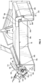
Fig. 5 is a side view of the closure assembly ofFig. 2 in the closed position; -
Fig. 6 is a rear view of the closure assembly ofFig. 2 in the closed position; -
Fig. 7 is a side view of the closure assembly ofFig. 2 in the open position; -
Fig. 8 is a rear view of the closure assembly ofFig. 2 in the open position; -
Fig. 9 is a cross-sectional view of the closure assembly ofFig. 2 in the closed position; -
Fig. 10 is a cross-sectional view of the closure assembly ofFig. 2 in a partially open position; -
Fig. 11 is a cross-sectional view of the closure assembly ofFig. 2 in a raised position; -
Fig. 12 is a side view of the closure assembly ofFig. 2 in the open position; -
Fig. 13 is a side view of one embodiment of a locking system for use with the closure assembly ofFig. 2 ; -
Fig. 14 is a top perspective view of the locking system ofFig. 13 ; -
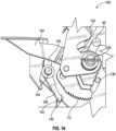
Fig. 15 is a top perspective view of the locking system ofFig. 13 ; -
Fig. 16 is a top perspective view of the locking system ofFig. 13 ; -
Fig. 17 is a top perspective view of the locking system ofFig. 13 ; -
Fig. 18 is a top perspective view of the locking system ofFig. 13 ; and -
Fig. 19 is a top perspective view of the locking system ofFig. 13 . - Corresponding reference numerals are used to indicate corresponding parts throughout the several views.
- The embodiments of the present disclosure described below are not intended to be exhaustive or to limit the disclosure to the precise forms in the following detailed description. Rather, the embodiments are chosen and described so that others skilled in the art may appreciate and understand the principles and practices of the present disclosure.
- Some of the benefits of the present disclosure include reducing the number of components and simplifying closure assemblies on tank openings of pressurized supply tanks. The unique closure assemblies are configured to block dirt and debris from reaching any of the lid seals in the closure assemblies. The closure assemblies are arranged at foot level to the operator such that the operator can easily reach the opening and closing movements of a large heavy tank lid of the closure assemblies. The tank lid contains one or more seals on the underside, and when the tank lid is in the closed position the one or more seals rest on one or more tank opening flanges to provide a pressurized seal. In any position of movement of the tank lid from open to close or close to open positions, the one or more seals on the underside of the tank lid are not damaged when opening and closing the tank lid.
- Referring now to
FIG. 1 , one embodiment of an air commodity dispersal ("ACD")ACD system 20, including an ACDcart 22 and aseeding machine 24, is illustrated. It is contemplated that other embodiments of theACD system 20 may be utilized with the present disclosure. During operation, the ACDsystem 20 is pulled by atractor 26 or otherwise moved across a field to distribute one or more agricultural commodities, such as seeds and fertilizer, held within the ACDcart 22. The agricultural commodities are carried by pressurized airstreams from the ACDcart 22 to theseeding machine 24, which then deposits or plants the commodities in the soil over which theACD system 20 travels. A network of air conduits orplumbing lines deposition tubes 32, which are arranged in different row units laterally spaced across theseeding machine 24. Additionally, a relatively small number ofmain air lines 28 may conduct the commodity-entrained airstreams from the ACDcart 22 to a number ofdistribution towers 34 mounted to theseeding machine 24 at various locations. Thedistribution towers 34 may then divide the airstreams amongst a larger number ofsecondary air lines 30, which then convey the commodity to thedeposition tubes 32 for planting or deposition within the ground. The row units of theseeding machine 24 may also include various ground-engaging tools 36, which assist in the commodity deposition process by, for example, opening furrows, packing soil, and closing furrows over the newly-deposited commodities. - Turning to
FIG. 2 , one embodiment of theACD cart 22 is illustrated. Other embodiments of theACD cart 22 may be utilized with the present disclosure. TheACD cart 22 includes a wheeled chassis orframe 38 on which one or more pressurized supply tanks are mounted, such aspressurized supply tank 40. Thepressurized supply tank 40 may have multiple internally-partitioned compartments or "commodity chambers" each suitable for holding one or more types of agricultural commodities. A number of tank openings 42 are provided inpressurized supply tank 40 and each provide physical access to a corresponding commodity chamber withintank 40. Threesuch tank openings 42a-c are visible inFIG. 2 and spaced along the topside ofpressurized supply tank 40. In further embodiments, theACD cart 22 may include fewer or a greater number of the tank openings 42, which may provide access to any number of compartments or chambers contained within thepressurized supply tank 40. The tank openings 42 are often produced to be relatively large to permit commodities to be spread about the commodity chambers in a substantially even or distributed manner during filling. The tank openings 42 may vary size in conjunction with their corresponding commodity chambers, which may likewise vary in size depending upon the particular volume of commodity each chamber is intended to hold. As shown inFIGS. 1 and2 , theACD cart 22 may be equipped withmovable conveyor arm 46 to facilitate filling of the commodity chambers corresponding to thetank openings 42a-c. -
Closure assemblies 44a-c are installed over thetank openings 42a-c, respectively. The closure assemblies 44 a-c includetank lids 48a-c, which are movable between closed and open positions. In the closed position, thetank lids 48a-c sealingly cover theirrespective tank openings 42a-c. Thetank lids 48a-c are positioned along anelongated platform 50 extending above and along the length of thepressurized supply tank 40. Theplatform 50 is surrounded by arailing 52 and accessible utilizing astairway 54 located adjacent the forward end ofpressurized supply tank 40. Theclosure assemblies 44a-c further includehandles 56a-c, respectively, which project upwardly from thetank lids 48a-c to allow an operator to move thelids 48a-c between their open and closed positions while standing on theplatform 50. Openings or gateways are provided in therailing 52 to provide access to thehandles 56a-c. - The
handle 56a will be described next however thehandles 56b-c are similar to handle 56a. Thehandle 56a includes a pair offront linkages 57a that are operably connected totank opening flanges 58a-b. Thehandle 56a includes a pair of hingedconnections 69a that operably connect thehandle 56a to thetank lid 48a. Thehandle 56a is operable between a closed position to an open position to lift thetank lid 48a and move thetank lid 48a along the pair ofguides 300a-b. - The
tank openings 42a-c may have relatively large planform dimensions to permit commodities to be spread about the commodity chambers in a substantially even or distributed manner during initial filling. Thetank lids 48a-c are thus likewise imparted with relatively large planform dimensions equivalent to or greater than the corresponding dimensions of theirrespective tank openings 42a-c. During operation of theACD cart 22, the commodity chambers are pressurized in conjunction with generation of the pressurized airstreams in which metered amounts of the commodities are entrained. The internal pressures created within the commodity chambers is typically about 2 pounds per square inch (about 14 kilopascal). Significant pressure loading forces may still be exerted on the interior of thetank lids 48a-c by the pressurized air within the commodity chambers, due to the relatively large surfaces of thetank lids 48a-c exposed to the elevated internal forces. -
FIGS. 3-12 are detailed views of theclosure assembly 44a illustrating thetank lid 48a in open and closed positions. As theclosure assembly 44a is similar to theclosure assemblies FIG. 2 , the following description is equally applicable thereto. Theclosure assembly 44b includes a first pair oftank opening flanges 58a-b that extend to and connect with a second pair oftank opening flanges 58c-d wherein the first and second pair oftank opening flanges 58a-d extend around the periphery of thetank opening 42a. - The
first opening flange 58c of the second pair oftank opening flanges 58c-d is configured to receive alocking system 100 thereon. Thefirst opening flange 58c includes a pair ofextension legs 71a that are separated a distance from each other. Each of theextensions legs 71a includes one or more mountingholes 73a to receive cross bars, fasteners, bolts, or other components from thelocking system 100 to mount thelocking system 100 to thefirst opening flange 58c. - The
second opening flange 58d of the second pair oftank opening flanges 58c-d is configured to engage aclevis mechanism 200 that extends from thetank lid 48a. Theclevis mechanism 200 includes aclevis leg 201 having a generally "L" shape with a horizontal portion attached to thecover 62 of thetank lid 48a, and theclevis leg 201 has a vertical portion the extends vertically downwardly to aclevis pin 202 attached thereto. Thesecond opening flange 58d includes aleg 60 that includes a clevis opening 61 sized to receive theclevis pin 202 from theclevis leg 201. Theclevis leg 201 is configured and sized to align theclevis pin 202 in the clevis opening 61 when thetank lid 48a is in the closed position. The clevis opening 61 is configured to enable rotation of theclevis pin 202 when thetank lid 48a is in a partially open position as illustrated inFig. 10 . The clevis opening 61 is configured to enable theclevis pin 202 to move away from the clevis opening 61 and begin exiting the clevis opening 61 when thetank lid 48a is in a raised position as illustrated inFig. 11 . The clevis opening 61 is configured to enable theclevis pin 202 to fully exit the clevis opening 61 when thetank lid 48a is in the open position as illustrated inFig. 12 . The clevis opening 61 has asemi-circular portion 63 that extends to a first and asecond clevis ramp 65a-b. Thesecond clevis ramp 65b also forms alip 67 upon which theclevis pin 202 may engage when thetank lid 48a is moved from the fully open position to the closed position. Theclevis pin 202 may not engage thelip 67 but instead enter the clevis opening 61 thereby avoiding thelip 67. The opening and closing of thetank lid 48a is described in more detail below. - The
tank lid 48a includes acover 62 that is sized to cover or enclose thetank opening 42a formed by the first and second pair oftank opening flanges 58a-d. Thecover 62 is generally rectangular in shape, however in other embodiments thecover 62 may be shaped differently. Thetank lid 48a includes a first pair of lid flanges 64a-b that extend to and connect with a second pair oflid flanges 64c-d wherein the first and second pair of lid flanges 64a-d extend around and exteriorly to the first and second pair oftank opening flanges 58a-d when thetank lid 48a is in a closed position. The first and second pair of lid flanges 64a-d also extend vertically downwardly from thecover 62 along their corresponding first and second pair oftank opening flanges 58a-d when thetank lid 48a is in a closed position. - In the illustrated embodiment, the
tank lid 48a also includes a lockingrail 76 mounted on thecover 62 and above the lid flange 64a wherein the lockingrail 76 is configured to receive one or more components from alocking system 100 as described in more detail below. In one form, the lockingrail 76 includes abar 80 that is configured to engage thelocking system 100. In other embodiments, thebar 80 is configured differently but still operates to engage thelocking system 100 as one of ordinary skill in the art would appreciate. The lockingrail 76 generally extends in an upward direction away from thecover 62. The lockingrail 76 has a rectangular cross-sectional shape but may be shaped differently in other embodiments. Moreover, in other embodiments, thetank lid 48a may not include the lockingrail 76 and instead thelid flange 64c is configured to engage thelocking system 100. - The
tank lid 48a includes a first pair of compression seals 78a-b (not illustrated) that are sized and attached to anunderside 79 of thecover 62 along the first pair of lid flanges 64a-b. Thetank lid 48a includes a second pair of compression seals 78c-d that are sized and attached to theunderside 79 of thecover 62 along the second pair oflid flanges 64c-d. The compression seals 78a-d cooperate with the first and second pair oftank opening flanges 58a-d to produce a 360 degree seal between thetank lid 48a and thetank opening 42a. The compression seals 78a-d may be integrally formed as a single (e.g., molded) piece, which forms a complete rectangle or ring having a planform shape generally conforming to the shape of thetank lid 48a. Alternatively, the compression seals 78a-d may be produced as discrete pieces or seals, which are separately affixed to the first and second pairs of lid flanges 64a-d, respectively. The compression seals 78a-d may be a cast urethane seal, or other materials, which is glued, bolted, or otherwise attached to thetank lid 48a. The compression seals 78a-d may be rectangular in cross-sectional shape or have other shapes, compositions, and may be attached to thetank lid 48a in other manners. Additionally, in further embodiments, multiple compression seals may be utilized. - The
tank lid 48a also includes a pair of front rollers 90a-b and a pair of rear rollers 92a-b wherein the front and rear rollers 90a and 92a are attached to and located on the lid flange 64a and the front andrear rollers lid flange 64b. The pairs of front and rear rollers 90a-b and 92a-b are configured to slide along a pair ofguides 300a-b. - The
closure assembly 44a also includes a pair ofguides 300a-b wherein theguide 300a is attached to thetank opening flange 58a and theguide 300b is attached to thetank opening flange 58b. Theguide 300a includes a track opening 302a and theguide 300b includes atrack opening 302b. Track opening 302a is substantially identical to thetrack opening 302b therefore only track opening 302b will be described.Track opening 302b extends along a length of theguide 300b wherein thetrack opening 302b includes afirst end opening 304b and aclearance window 314b that corresponds to thetank lid 48a being in the closed position. In the closed position, thefront roller 90b rests in thefirst end opening 304b and therear roller 92b rests in theclearance window 314b. Thetrack opening 302b includes a second end opening 306b that corresponds to thetank lid 48a being in the open position. Thetrack opening 302b includes anarc portion 308b that engages thefirst end opening 304b and generally forms an angle A relative to a vertical reference line. The angle A is typically between 0 and 45 degrees but can be larger than 45 degrees in other embodiments. Thearc portion 308b may be curved or straight. Thearc portion 308b has a length that corresponds to raising thetank lid 48a to the raised position such that thecompression seal 78d is decompressed as thetank lid 48a lifts away from thetank opening flange 58d. Thetrack opening 302b includes aclimax portion 310b that is tangent along thearc portion 308b and is the highest peak that thefront roller 90b will travel along thetrack opening 302b. When thefront roller 90b is in theclimax portion 310b, thecompression seal 78d has cleared thetank opening flange 58d such that thecompression seal 78d is not damaged as thetank lid 48a slides up and over thetank opening flange 58d. Thetrack opening 302b includes arunner portion 312b that extends from theclimax portion 310b to the second end opening 306b. Therunner portion 312b forms an angle B relative to a horizontal reference line wherein the angle B is typically between 10 to 45 degrees but may be larger in other embodiments. Therunner portion 312b has a length that substantially corresponds to the length oftank opening flange 58b such that when thetank lid 48a is in the open position the agricultural commodity can be placed in thetank opening 42a without touching thetank lid 48a and thetank lid 48a does not block any portion of thetank opening 42a. - The operation from an open to closed positioned of the
closure assemblies 44a-c will now be described with reference to theclosure assembly 44a asclosure assemblies 44b-c operate in a similar fashion. The operator uses thehandle 56a to move thetank lid 48a from the open to closed positions, and from the closed to open positions. From the closed position illustrated inFig. 9 to a partially open position as illustrated inFig. 10 , the operator engages thelocking system 100 to release thetank lid 48a such that thecompression seal 78c and thecompression seal 78d are decompressed. Also illustrated inFig. 10 is thetank lid 48a and thelid flange 64c that is raised above thetank opening flange 58c as theclevis pin 202 pivots or rotates in the clevis opening 61 such that thetank lid 48a is now propped open a few degrees from the closed position. As the front rollers 90a-b move along the arc portions 308a-b to the climax portions 310a-b and thetank lid 48a is in the raised position illustrated inFig. 11 , theclevis pin 202 is released from the clevis opening 61. Thetank lid 48a follows an arc motion along the arc portions 308a-b until the front rollers 90a-b reach the climax portions 310a-b such that thetank lid 48a is raised partially above thetank opening flange 58b. Thecompression seal 78d has rotated and cleared or moved past thetank opening flange 58d. As the front rollers 90a-b continue to move from the climax portions 310a-b along the length of the runner portions 312a-b, thetank lid 48a follows a linear downward motion to clear thetank opening 42a. As the front rollers 90a-b move along the runner portions 312a-b to the second end opening 306b, generally thetank lid 48a is lower than the top of thetank opening flanges 58a-d to allow clearance for filling the corresponding commodity chamber withintank 40 and visibility of filling from ground level. To move thetank lid 48a from the open position inFig. 12 to the raised position inFig. 11 , i.e., to begin to partially close thetank lid 48a, thetank lid 48a slides along the track openings 302a-b with thecompression seal 78d raised above thetank opening flange 58d until theclevis pin 202 makes contact with thelip 67 on thesecond clevis ramp 65b and thecompression seal 78d makes contact with thetank opening flange 58d. From the raised position inFig. 11 to the partially open position inFig. 10 , the travel motion of thetank lid 48a changes to an arc motion as the front rollers 90a-b travel along the arc portions 308a-b. When the front rollers 90a-b reach the first end openings 304a-b, thetank lid 48a is in the closed position illustrated inFig. 9 and thecompression seal 78c engages thetank opening flange 58c and the remaining compression seals 78a,b,d engage their respectivetank opening flange 58a,b,d. The operator engages thelocking system 100 to lock thetank lid 48a into the closed position. - Referring now to
Figs. 9-12 andFigs. 13-19 , thelocking system 100 will now be described with reference to theclosure assembly 44a. Thelocking system 100 is one embodiment that can be used with theclosure assembly 44a, however other forms of the locking systems can be used with theclosure assembly 44a. Thelocking system 100 retains thetank lid 48a in a closed position until thelocking system 100 is activated. Once thelocking system 100 is activated, such as by an operator, thelocking system 100 releases from thetank lid 48a and thelocking system 100 engages thetank lid 48a to lift thetank lid 48a into a slightly open position as illustrated inFig. 10 . Thereafter the operator uses thehandle 56a to move thetank lid 48a into the fully opened position. - The
locking system 100 includes afirst foot pedal 102, asecond foot pedal 104, and a lockingpawl 106. Thefirst foot pedal 102 includes acam shape latch 110 that engages thebar 80 to lock thetank lid 48a in a closed position as illustrated inFigs. 9 and13 . Thefirst foot pedal 102 includes anengagement portion 112 to engage and retain the lockingpawl 106 in the closed position. Theengagement portion 112 includes one ormore teeth 113 configured to engage the lockingpawl 106. Thefirst foot pedal 102 includes afoot engagement portion 114 that is shaped to receive an operator's foot thereon and operates as a lever to push thecam shape latch 110 into engagement with thebar 80 as thefirst foot pedal 102 rotates about a rotation axis or pivot 120 to lock thetank lid 48a closed. Thefirst foot pedal 102 includes abump stop 116 that spans between afirst leg 122 and asecond leg 124 of thefirst foot pedal 102. - The
second foot pedal 104 includes anengagement portion 130 to engage the lockingpawl 106 and maintain the lockingpawl 106 in the closed position. Thesecond foot pedal 104 includes afoot engagement portion 132 that is shaped to receive an operator's foot thereon. Thesecond foot pedal 104 includes a pair oflegs 134 that are configured to engage acam 136 that extends from theextension legs 71a wherein the pair oflegs 134 rotate to engage thecam 136 to stop thesecond foot pedal 104 from further rotation. Thesecond foot pedal 104 includes akicker portion 138 that engages the bump stop 116 of thefirst foot pedal 102. Thesecond foot pedal 104 rotates about the rotation axis orpivot 120. - The locking
pawl 106 includes arelease portion 140 opposite a lockingportion 142 wherein therelease portion 140 is separated from the lockingportion 142 by arotational axis 144 about which the lockingpawl 106 rotates. In one form, the lockingpawl 106 rotates from an angle of about 47 degrees to an angle of about 33.5 degrees for a net angle movement of about 14 or 15 degrees. Therelease portion 140 is configured to engage theengagement portion 130. The lockingportion 142 includes one ormore teeth 146 to engage the one ormore teeth 113 on theengagement portion 112 of thefirst foot pedal 102. Thecam shape latch 110 along with the one ormore teeth 113 help to keep thefirst foot pedal 102 in a home or closed position as the pressure in tank will apply a large force to the underside of the lid. The lockingpawl 106 also provides a "click" giving the operator an indication that the lockingpawl 106 is set. The lockingpawl 106 is attached to theextension legs 71a at therotational axis 144 with a bolt orother fastener 150 through one of the mountingholes 73a. - To lock the
locking system 100 onto thetank lid 48a, thetank lid 48a is closed onto thetank opening 42a such as illustrated inFigs. 3 and17 . Thefirst foot pedal 102 and thesecond foot pedal 104 are in the home position as illustrated inFig. 17 . The home position is defined as thetank lid 48a resting on thetank opening flanges 58a-d, and the first andsecond foot pedals tank lid 48a onto thetank opening 42a, an operator engages thefoot engagement portion 114 of thefirst foot pedal 102 and presses thefoot engagement portion 114 downward so that thefoot engagement portion 114 rotates clockwise about the rotation axis or pivot 120 until thecam shape latch 110 engages thebar 80 to lock thetank lid 48a in a closed position as illustrated inFigs. 18 and 19 . In one form, thefirst foot pedal 102 rotates from an angle of about 64 degrees to an angle of about 28 degrees for a net angle movement of 36 degrees. - In
Fig. 14 , the operator engages thefoot engagement portion 132 of thesecond foot pedal 104 to cause thesecond foot pedal 104 to rotate counterclockwise about the rotation axis or pivot 120 such that theengagement portion 130 engages therelease portion 140 of the lockingpawl 106 and causes the lockingpawl 106 to rotate about therotational axis 144 and bolt orother fastener 150 in a clockwise direction to release the lockingpawl 106 from theengagement portion 112 of thefirst foot pedal 102. In one form, thesecond foot pedal 104 rotates from an angle of about 106 degrees to an angle of about 70 degrees for a net angle movement of 36 degrees. - In
Fig. 15 , the operator continues to press on thefoot engagement portion 132 of thesecond foot pedal 104 to cause thesecond foot pedal 104 to rotate counterclockwise about the rotation axis or pivot 120 such that thekicker portion 138 engages the bump stop 116 of thefirst foot pedal 102 to cause thefirst foot pedal 102 to rotate about the rotation axis or pivot 120 until thecam shape latch 110 disengages or releases from thebar 80. Thefirst foot pedal 102 returns to the home position and thetank lid 48a is unlocked from thetank opening 42a. - To open the
tank lid 48a, thehandle 56a is engaged such that the operator presses down on thehandle 56a and the pair offront linkages 57a as the front rollers 90a-b and the rear rollers 92a-b travel along the track openings 302a-b of the pair ofguides 300a-b as described above. Thehandle 56a is operable between a closed position and an open position to lift thetank lid 48a and move thetank lid 48a along the pair ofguides 300a-b to a fully open position. The operations are reversed to lift thetank lid 48a from the open position to the fully closed position and lock thelocking system 100. - Beneficially, the
locking system 100 uses fewer parts at least in part because of the single latching operation of thelocking system 100. Beneficially, the rear pivot, i.e., theclevis pin 202 in the clevis opening 61 assists to keep thetank lid 48a clamped under the air pressure within thesupply tank 40.
Claims (8)
- Supply tank (40) for an agricultural machine (24), the supply tank (40) comprising a tank opening (42a-c) and a closure assembly (44a-c), wherein the closure assembly comprising:a tank opening flange (58a-d) configured to surround the tank opening (42a-c);a tank lid (48a-c) operable between an open position and a closed position, the tank lid (48a-c) while in the closed position configured to cover the tank opening, the tank lid (48a-c) while in the open position configured to uncover the tank opening, the tank lid (48a-c) having a first lid flange (64a-d) opposite a second lid flange (64a-d);a plurality of sliding mechanisms (90a-b, 92a-b) attached to the tank lid (48a-c); anda pair of guides (300a-b) attached to opposite sides of the tank opening flange (58a-d), characterized in thateach of the pair of guides (300a-b) defines a track opening (302a-b) for receiving the plurality of sliding mechanisms such that the tank lid (48a-c) slides along the track openings (302a-b) of the pair of guides (300a-b) when the tank lid (48a-c) is operated between the open and closed positions; and in thatthe closure assembly (44a-c) further comprises a clevis mechanism (200) operably attached to both of the second lid flange (64a-d) and the tank opening flange (58a-d) to enable the tank lid (48a-c) to pivot about the tank opening flange (58a-d).
- Supply tank (40) of claim 1, further comprising:
one or more compression seals (78a-d) attached to an underside of the tank lid (48a-c), the one or more compression seals (78a-d) disposed between the tank opening flange (58a-d) and the tank lid (48a-c) when the tank lid (48a-c) is in the closed position. - Supply tank (40) of claim 1 or 2, further comprising:a locking system (100) configured to retain the tank lid (48a-c) in a locked position,wherein the locking system (100) is configured to operably engage and lift the tank lid (48a-c) away from the tank opening.
- Supply tank (40) of one of the claims 1 to 3, wherein the clevis mechanism (200) includes a clevis pin (202) operably engaged with a clevis opening (61) in the tank opening flange (58a-d) such that the clevis pin (202) rotates in the clevis opening (61).
- Supply tank (40) of claim 4, wherein the sliding mechanisms include rollers (90a-b, 92a-b) that move along the track openings (302a-b) to a climax portion of the track openings (302a-b) such that the tank lid (48a-c) is in a raised position and the clevis pin (202) is released from the clevis opening (61).
- Supply tank (40) of claim 5, wherein at least one of the rollers (90a-b, 92a-b) in the climax portion of the track opening includes at least one of the compression seals (78a-d) having cleared the tank opening flange (58a-d).
- Supply tank (40) of one of the claims 2 to 6, wherein the sliding mechanisms include rollers (90a-b, 92a-b) that move along the track openings (302a-b) to an end opening such that the tank lid (48a-c) is lower than a top of the tank opening flange (58a-d) and the tank opening is uncovered when the tank lid (48a-c) is in the open position.
- Agricultural machine (24) with a supply tank (40) according to one of the claims 1 to 7.
Applications Claiming Priority (1)
| Application Number | Priority Date | Filing Date | Title |
|---|---|---|---|
| US17/482,551 US12063878B2 (en) | 2021-09-23 | 2021-09-23 | Large sealing lid with slides and lock |
Publications (2)
| Publication Number | Publication Date |
|---|---|
| EP4154695A1 EP4154695A1 (en) | 2023-03-29 |
| EP4154695B1 true EP4154695B1 (en) | 2024-04-03 |
Family
ID=83228684
Family Applications (1)
| Application Number | Title | Priority Date | Filing Date |
|---|---|---|---|
| EP22194141.2A Active EP4154695B1 (en) | 2021-09-23 | 2022-09-06 | Supply tank and agricultural machine with such |
Country Status (5)
| Country | Link |
|---|---|
| US (2) | US12063878B2 (en) |
| EP (1) | EP4154695B1 (en) |
| AU (1) | AU2022221484A1 (en) |
| BR (1) | BR102022013013A2 (en) |
| CA (1) | CA3172094A1 (en) |
Family Cites Families (6)
| Publication number | Priority date | Publication date | Assignee | Title |
|---|---|---|---|---|
| US2960367A (en) * | 1959-03-23 | 1960-11-15 | Frank J Yodice | Slide-dome hatch for tanks |
| US3961723A (en) * | 1974-07-12 | 1976-06-08 | Eckel Industries, Inc. | Receptacle with sliding cover |
| KR200273406Y1 (en) | 1999-04-29 | 2002-05-04 | 정봉화 | Door open device for a tank of a vehicle |
| US20060213909A1 (en) * | 2005-03-23 | 2006-09-28 | Epp Richard J | Top closure member for a storage bin |
| US10322658B2 (en) | 2015-09-14 | 2019-06-18 | Deere & Company | Sealed closure arrangement for tank opening of agricultural machine |
| US11014741B2 (en) * | 2015-09-14 | 2021-05-25 | Deere & Company | Closure arrangement for tank opening of agricultural machine |
-
2021
- 2021-09-23 US US17/482,551 patent/US12063878B2/en active Active
-
2022
- 2022-06-29 BR BR102022013013-2A patent/BR102022013013A2/en unknown
- 2022-08-18 CA CA3172094A patent/CA3172094A1/en active Pending
- 2022-08-25 AU AU2022221484A patent/AU2022221484A1/en active Pending
- 2022-09-06 EP EP22194141.2A patent/EP4154695B1/en active Active
-
2024
- 2024-08-19 US US18/808,139 patent/US20240407282A1/en active Pending
Also Published As
| Publication number | Publication date |
|---|---|
| CA3172094A1 (en) | 2023-03-23 |
| AU2022221484A1 (en) | 2023-04-06 |
| US12063878B2 (en) | 2024-08-20 |
| US20240407282A1 (en) | 2024-12-12 |
| BR102022013013A2 (en) | 2023-04-04 |
| US20230104651A1 (en) | 2023-04-06 |
| EP4154695A1 (en) | 2023-03-29 |
Similar Documents
| Publication | Publication Date | Title |
|---|---|---|
| US7644670B2 (en) | Paired single disc opener unit | |
| US11014741B2 (en) | Closure arrangement for tank opening of agricultural machine | |
| US3872805A (en) | Planting machine | |
| EP4154695B1 (en) | Supply tank and agricultural machine with such | |
| US8505473B1 (en) | Paired single disc opener unit | |
| US10322658B2 (en) | Sealed closure arrangement for tank opening of agricultural machine | |
| EP1321018B1 (en) | Agricultural machine frame | |
| JP2002305927A (en) | Shutter structure for hopper | |
| CN114532019A (en) | Rice transplanter | |
| JPH0139145Y2 (en) | ||
| JP2007000066A (en) | Seedling planting machine | |
| JP2510921Y2 (en) | Rice planting equipment for rice transplanters | |
| JPS61185113A (en) | Rice transplanter with fertilization device | |
| CN114532021A (en) | Seedling raising box and rice transplanter | |
| GB2277665A (en) | Seed sowing machine | |
| JP3670087B2 (en) | Rice transplanter fertilizer | |
| US1282798A (en) | Planter. | |
| JPH0737462Y2 (en) | Fertilizer supply device in fertilizer applicator | |
| JP3409152B2 (en) | Rice transplanter | |
| US720211A (en) | Corn-planter. | |
| JP2004141099A (en) | Fertilizer | |
| JPH0317616Y2 (en) | ||
| JP2025019709A (en) | Ride-on seedling transplanter | |
| JP2536363B2 (en) | Riding rice transplanter with fertilizer application | |
| JP2711399B2 (en) | Farm work vehicle with walking steps |
Legal Events
| Date | Code | Title | Description |
|---|---|---|---|
| PUAI | Public reference made under article 153(3) epc to a published international application that has entered the european phase |
Free format text: ORIGINAL CODE: 0009012 |
|
| STAA | Information on the status of an ep patent application or granted ep patent |
Free format text: STATUS: THE APPLICATION HAS BEEN PUBLISHED |
|
| AK | Designated contracting states |
Kind code of ref document: A1 Designated state(s): AL AT BE BG CH CY CZ DE DK EE ES FI FR GB GR HR HU IE IS IT LI LT LU LV MC MK MT NL NO PL PT RO RS SE SI SK SM TR |
|
| STAA | Information on the status of an ep patent application or granted ep patent |
Free format text: STATUS: REQUEST FOR EXAMINATION WAS MADE |
|
| 17P | Request for examination filed |
Effective date: 20230929 |
|
| RBV | Designated contracting states (corrected) |
Designated state(s): AL AT BE BG CH CY CZ DE DK EE ES FI FR GB GR HR HU IE IS IT LI LT LU LV MC MK MT NL NO PL PT RO RS SE SI SK SM TR |
|
| GRAP | Despatch of communication of intention to grant a patent |
Free format text: ORIGINAL CODE: EPIDOSNIGR1 |
|
| STAA | Information on the status of an ep patent application or granted ep patent |
Free format text: STATUS: GRANT OF PATENT IS INTENDED |
|
| RIC1 | Information provided on ipc code assigned before grant |
Ipc: B60P 3/22 20060101ALI20231018BHEP Ipc: A01C 15/00 20060101AFI20231018BHEP |
|
| INTG | Intention to grant announced |
Effective date: 20231113 |
|
| GRAS | Grant fee paid |
Free format text: ORIGINAL CODE: EPIDOSNIGR3 |
|
| GRAA | (expected) grant |
Free format text: ORIGINAL CODE: 0009210 |
|
| STAA | Information on the status of an ep patent application or granted ep patent |
Free format text: STATUS: THE PATENT HAS BEEN GRANTED |
|
| AK | Designated contracting states |
Kind code of ref document: B1 Designated state(s): AL AT BE BG CH CY CZ DE DK EE ES FI FR GB GR HR HU IE IS IT LI LT LU LV MC MK MT NL NO PL PT RO RS SE SI SK SM TR |
|
| REG | Reference to a national code |
Ref country code: CH Ref legal event code: EP |
|
| REG | Reference to a national code |
Ref country code: DE Ref legal event code: R096 Ref document number: 602022002682 Country of ref document: DE |
|
| REG | Reference to a national code |
Ref country code: IE Ref legal event code: FG4D |
|
| REG | Reference to a national code |
Ref country code: LT Ref legal event code: MG9D |
|
| REG | Reference to a national code |
Ref country code: NL Ref legal event code: MP Effective date: 20240403 |
|
| REG | Reference to a national code |
Ref country code: AT Ref legal event code: MK05 Ref document number: 1671168 Country of ref document: AT Kind code of ref document: T Effective date: 20240403 |
|
| PG25 | Lapsed in a contracting state [announced via postgrant information from national office to epo] |
Ref country code: NL Free format text: LAPSE BECAUSE OF FAILURE TO SUBMIT A TRANSLATION OF THE DESCRIPTION OR TO PAY THE FEE WITHIN THE PRESCRIBED TIME-LIMIT Effective date: 20240403 |
|
| PG25 | Lapsed in a contracting state [announced via postgrant information from national office to epo] |
Ref country code: NL Free format text: LAPSE BECAUSE OF FAILURE TO SUBMIT A TRANSLATION OF THE DESCRIPTION OR TO PAY THE FEE WITHIN THE PRESCRIBED TIME-LIMIT Effective date: 20240403 |
|
| PG25 | Lapsed in a contracting state [announced via postgrant information from national office to epo] |
Ref country code: IS Free format text: LAPSE BECAUSE OF FAILURE TO SUBMIT A TRANSLATION OF THE DESCRIPTION OR TO PAY THE FEE WITHIN THE PRESCRIBED TIME-LIMIT Effective date: 20240803 |
|
| PG25 | Lapsed in a contracting state [announced via postgrant information from national office to epo] |
Ref country code: BG Free format text: LAPSE BECAUSE OF FAILURE TO SUBMIT A TRANSLATION OF THE DESCRIPTION OR TO PAY THE FEE WITHIN THE PRESCRIBED TIME-LIMIT Effective date: 20240403 |
|
| PG25 | Lapsed in a contracting state [announced via postgrant information from national office to epo] |
Ref country code: HR Free format text: LAPSE BECAUSE OF FAILURE TO SUBMIT A TRANSLATION OF THE DESCRIPTION OR TO PAY THE FEE WITHIN THE PRESCRIBED TIME-LIMIT Effective date: 20240403 Ref country code: FI Free format text: LAPSE BECAUSE OF FAILURE TO SUBMIT A TRANSLATION OF THE DESCRIPTION OR TO PAY THE FEE WITHIN THE PRESCRIBED TIME-LIMIT Effective date: 20240403 |
|
| PG25 | Lapsed in a contracting state [announced via postgrant information from national office to epo] |
Ref country code: GR Free format text: LAPSE BECAUSE OF FAILURE TO SUBMIT A TRANSLATION OF THE DESCRIPTION OR TO PAY THE FEE WITHIN THE PRESCRIBED TIME-LIMIT Effective date: 20240704 |
|
| PG25 | Lapsed in a contracting state [announced via postgrant information from national office to epo] |
Ref country code: PT Free format text: LAPSE BECAUSE OF FAILURE TO SUBMIT A TRANSLATION OF THE DESCRIPTION OR TO PAY THE FEE WITHIN THE PRESCRIBED TIME-LIMIT Effective date: 20240805 |
|
| PG25 | Lapsed in a contracting state [announced via postgrant information from national office to epo] |
Ref country code: ES Free format text: LAPSE BECAUSE OF FAILURE TO SUBMIT A TRANSLATION OF THE DESCRIPTION OR TO PAY THE FEE WITHIN THE PRESCRIBED TIME-LIMIT Effective date: 20240403 |
|
| PG25 | Lapsed in a contracting state [announced via postgrant information from national office to epo] |
Ref country code: CZ Free format text: LAPSE BECAUSE OF FAILURE TO SUBMIT A TRANSLATION OF THE DESCRIPTION OR TO PAY THE FEE WITHIN THE PRESCRIBED TIME-LIMIT Effective date: 20240403 |
|
| PG25 | Lapsed in a contracting state [announced via postgrant information from national office to epo] |
Ref country code: AT Free format text: LAPSE BECAUSE OF FAILURE TO SUBMIT A TRANSLATION OF THE DESCRIPTION OR TO PAY THE FEE WITHIN THE PRESCRIBED TIME-LIMIT Effective date: 20240403 |
|
| PG25 | Lapsed in a contracting state [announced via postgrant information from national office to epo] |
Ref country code: PL Free format text: LAPSE BECAUSE OF FAILURE TO SUBMIT A TRANSLATION OF THE DESCRIPTION OR TO PAY THE FEE WITHIN THE PRESCRIBED TIME-LIMIT Effective date: 20240403 |
|
| PG25 | Lapsed in a contracting state [announced via postgrant information from national office to epo] |
Ref country code: LV Free format text: LAPSE BECAUSE OF FAILURE TO SUBMIT A TRANSLATION OF THE DESCRIPTION OR TO PAY THE FEE WITHIN THE PRESCRIBED TIME-LIMIT Effective date: 20240403 |
|
| PG25 | Lapsed in a contracting state [announced via postgrant information from national office to epo] |
Ref country code: PT Free format text: LAPSE BECAUSE OF FAILURE TO SUBMIT A TRANSLATION OF THE DESCRIPTION OR TO PAY THE FEE WITHIN THE PRESCRIBED TIME-LIMIT Effective date: 20240805 Ref country code: PL Free format text: LAPSE BECAUSE OF FAILURE TO SUBMIT A TRANSLATION OF THE DESCRIPTION OR TO PAY THE FEE WITHIN THE PRESCRIBED TIME-LIMIT Effective date: 20240403 Ref country code: NO Free format text: LAPSE BECAUSE OF FAILURE TO SUBMIT A TRANSLATION OF THE DESCRIPTION OR TO PAY THE FEE WITHIN THE PRESCRIBED TIME-LIMIT Effective date: 20240703 Ref country code: LV Free format text: LAPSE BECAUSE OF FAILURE TO SUBMIT A TRANSLATION OF THE DESCRIPTION OR TO PAY THE FEE WITHIN THE PRESCRIBED TIME-LIMIT Effective date: 20240403 Ref country code: IS Free format text: LAPSE BECAUSE OF FAILURE TO SUBMIT A TRANSLATION OF THE DESCRIPTION OR TO PAY THE FEE WITHIN THE PRESCRIBED TIME-LIMIT Effective date: 20240803 Ref country code: HR Free format text: LAPSE BECAUSE OF FAILURE TO SUBMIT A TRANSLATION OF THE DESCRIPTION OR TO PAY THE FEE WITHIN THE PRESCRIBED TIME-LIMIT Effective date: 20240403 Ref country code: GR Free format text: LAPSE BECAUSE OF FAILURE TO SUBMIT A TRANSLATION OF THE DESCRIPTION OR TO PAY THE FEE WITHIN THE PRESCRIBED TIME-LIMIT Effective date: 20240704 Ref country code: FI Free format text: LAPSE BECAUSE OF FAILURE TO SUBMIT A TRANSLATION OF THE DESCRIPTION OR TO PAY THE FEE WITHIN THE PRESCRIBED TIME-LIMIT Effective date: 20240403 Ref country code: ES Free format text: LAPSE BECAUSE OF FAILURE TO SUBMIT A TRANSLATION OF THE DESCRIPTION OR TO PAY THE FEE WITHIN THE PRESCRIBED TIME-LIMIT Effective date: 20240403 Ref country code: CZ Free format text: LAPSE BECAUSE OF FAILURE TO SUBMIT A TRANSLATION OF THE DESCRIPTION OR TO PAY THE FEE WITHIN THE PRESCRIBED TIME-LIMIT Effective date: 20240403 Ref country code: BG Free format text: LAPSE BECAUSE OF FAILURE TO SUBMIT A TRANSLATION OF THE DESCRIPTION OR TO PAY THE FEE WITHIN THE PRESCRIBED TIME-LIMIT Effective date: 20240403 Ref country code: AT Free format text: LAPSE BECAUSE OF FAILURE TO SUBMIT A TRANSLATION OF THE DESCRIPTION OR TO PAY THE FEE WITHIN THE PRESCRIBED TIME-LIMIT Effective date: 20240403 Ref country code: RS Free format text: LAPSE BECAUSE OF FAILURE TO SUBMIT A TRANSLATION OF THE DESCRIPTION OR TO PAY THE FEE WITHIN THE PRESCRIBED TIME-LIMIT Effective date: 20240703 |
|
| REG | Reference to a national code |
Ref country code: DE Ref legal event code: R097 Ref document number: 602022002682 Country of ref document: DE |
|
| PG25 | Lapsed in a contracting state [announced via postgrant information from national office to epo] |
Ref country code: DK Free format text: LAPSE BECAUSE OF FAILURE TO SUBMIT A TRANSLATION OF THE DESCRIPTION OR TO PAY THE FEE WITHIN THE PRESCRIBED TIME-LIMIT Effective date: 20240403 |
|
| PG25 | Lapsed in a contracting state [announced via postgrant information from national office to epo] |
Ref country code: EE Free format text: LAPSE BECAUSE OF FAILURE TO SUBMIT A TRANSLATION OF THE DESCRIPTION OR TO PAY THE FEE WITHIN THE PRESCRIBED TIME-LIMIT Effective date: 20240403 |
|
| PG25 | Lapsed in a contracting state [announced via postgrant information from national office to epo] |
Ref country code: SK Free format text: LAPSE BECAUSE OF FAILURE TO SUBMIT A TRANSLATION OF THE DESCRIPTION OR TO PAY THE FEE WITHIN THE PRESCRIBED TIME-LIMIT Effective date: 20240403 Ref country code: RO Free format text: LAPSE BECAUSE OF FAILURE TO SUBMIT A TRANSLATION OF THE DESCRIPTION OR TO PAY THE FEE WITHIN THE PRESCRIBED TIME-LIMIT Effective date: 20240403 |
|
| PG25 | Lapsed in a contracting state [announced via postgrant information from national office to epo] |
Ref country code: SM Free format text: LAPSE BECAUSE OF FAILURE TO SUBMIT A TRANSLATION OF THE DESCRIPTION OR TO PAY THE FEE WITHIN THE PRESCRIBED TIME-LIMIT Effective date: 20240403 |
|
| PG25 | Lapsed in a contracting state [announced via postgrant information from national office to epo] |
Ref country code: SM Free format text: LAPSE BECAUSE OF FAILURE TO SUBMIT A TRANSLATION OF THE DESCRIPTION OR TO PAY THE FEE WITHIN THE PRESCRIBED TIME-LIMIT Effective date: 20240403 Ref country code: SK Free format text: LAPSE BECAUSE OF FAILURE TO SUBMIT A TRANSLATION OF THE DESCRIPTION OR TO PAY THE FEE WITHIN THE PRESCRIBED TIME-LIMIT Effective date: 20240403 Ref country code: RO Free format text: LAPSE BECAUSE OF FAILURE TO SUBMIT A TRANSLATION OF THE DESCRIPTION OR TO PAY THE FEE WITHIN THE PRESCRIBED TIME-LIMIT Effective date: 20240403 Ref country code: EE Free format text: LAPSE BECAUSE OF FAILURE TO SUBMIT A TRANSLATION OF THE DESCRIPTION OR TO PAY THE FEE WITHIN THE PRESCRIBED TIME-LIMIT Effective date: 20240403 Ref country code: DK Free format text: LAPSE BECAUSE OF FAILURE TO SUBMIT A TRANSLATION OF THE DESCRIPTION OR TO PAY THE FEE WITHIN THE PRESCRIBED TIME-LIMIT Effective date: 20240403 |
|
| PLBE | No opposition filed within time limit |
Free format text: ORIGINAL CODE: 0009261 |
|
| STAA | Information on the status of an ep patent application or granted ep patent |
Free format text: STATUS: NO OPPOSITION FILED WITHIN TIME LIMIT |
|
| 26N | No opposition filed |
Effective date: 20250106 |
|
| PG25 | Lapsed in a contracting state [announced via postgrant information from national office to epo] |
Ref country code: SI Free format text: LAPSE BECAUSE OF FAILURE TO SUBMIT A TRANSLATION OF THE DESCRIPTION OR TO PAY THE FEE WITHIN THE PRESCRIBED TIME-LIMIT Effective date: 20240403 Ref country code: MC Free format text: LAPSE BECAUSE OF FAILURE TO SUBMIT A TRANSLATION OF THE DESCRIPTION OR TO PAY THE FEE WITHIN THE PRESCRIBED TIME-LIMIT Effective date: 20240403 |
|
| PG25 | Lapsed in a contracting state [announced via postgrant information from national office to epo] |
Ref country code: LU Free format text: LAPSE BECAUSE OF NON-PAYMENT OF DUE FEES Effective date: 20240906 |
|
| REG | Reference to a national code |
Ref country code: BE Ref legal event code: MM Effective date: 20240930 |
|
| PG25 | Lapsed in a contracting state [announced via postgrant information from national office to epo] |
Ref country code: BE Free format text: LAPSE BECAUSE OF NON-PAYMENT OF DUE FEES Effective date: 20240930 |
|
| PG25 | Lapsed in a contracting state [announced via postgrant information from national office to epo] |
Ref country code: IE Free format text: LAPSE BECAUSE OF NON-PAYMENT OF DUE FEES Effective date: 20240906 |
|
| PG25 | Lapsed in a contracting state [announced via postgrant information from national office to epo] |
Ref country code: SE Free format text: LAPSE BECAUSE OF FAILURE TO SUBMIT A TRANSLATION OF THE DESCRIPTION OR TO PAY THE FEE WITHIN THE PRESCRIBED TIME-LIMIT Effective date: 20240403 |
|
| PGFP | Annual fee paid to national office [announced via postgrant information from national office to epo] |
Ref country code: DE Payment date: 20250820 Year of fee payment: 4 |
|
| PGFP | Annual fee paid to national office [announced via postgrant information from national office to epo] |
Ref country code: FR Payment date: 20250925 Year of fee payment: 4 |
|
| PG25 | Lapsed in a contracting state [announced via postgrant information from national office to epo] |
Ref country code: IT Free format text: LAPSE BECAUSE OF FAILURE TO SUBMIT A TRANSLATION OF THE DESCRIPTION OR TO PAY THE FEE WITHIN THE PRESCRIBED TIME-LIMIT Effective date: 20240403 Ref country code: CY Free format text: LAPSE BECAUSE OF FAILURE TO SUBMIT A TRANSLATION OF THE DESCRIPTION OR TO PAY THE FEE WITHIN THE PRESCRIBED TIME-LIMIT; INVALID AB INITIO Effective date: 20220906 |
|
| PG25 | Lapsed in a contracting state [announced via postgrant information from national office to epo] |
Ref country code: HU Free format text: LAPSE BECAUSE OF FAILURE TO SUBMIT A TRANSLATION OF THE DESCRIPTION OR TO PAY THE FEE WITHIN THE PRESCRIBED TIME-LIMIT; INVALID AB INITIO Effective date: 20220906 |