EP4154057B1 - An eyewear frame - Google Patents
An eyewear frame Download PDFInfo
- Publication number
- EP4154057B1 EP4154057B1 EP21727426.5A EP21727426A EP4154057B1 EP 4154057 B1 EP4154057 B1 EP 4154057B1 EP 21727426 A EP21727426 A EP 21727426A EP 4154057 B1 EP4154057 B1 EP 4154057B1
- Authority
- EP
- European Patent Office
- Prior art keywords
- electronic devices
- close
- communication systems
- range
- temple
- Prior art date
- Legal status (The legal status is an assumption and is not a legal conclusion. Google has not performed a legal analysis and makes no representation as to the accuracy of the status listed.)
- Active
Links
Images

Classifications
-
- G—PHYSICS
- G02—OPTICS
- G02C—SPECTACLES; SUNGLASSES OR GOGGLES INSOFAR AS THEY HAVE THE SAME FEATURES AS SPECTACLES; CONTACT LENSES
- G02C11/00—Non-optical adjuncts; Attachment thereof
- G02C11/10—Electronic devices other than hearing aids
-
- H—ELECTRICITY
- H04—ELECTRIC COMMUNICATION TECHNIQUE
- H04B—TRANSMISSION
- H04B1/00—Details of transmission systems, not covered by a single one of groups H04B3/00 - H04B13/00; Details of transmission systems not characterised by the medium used for transmission
- H04B1/38—Transceivers, i.e. devices in which transmitter and receiver form a structural unit and in which at least one part is used for functions of transmitting and receiving
- H04B1/3827—Portable transceivers
- H04B1/385—Transceivers carried on the body, e.g. in helmets
-
- H—ELECTRICITY
- H04—ELECTRIC COMMUNICATION TECHNIQUE
- H04B—TRANSMISSION
- H04B5/00—Near-field transmission systems, e.g. inductive or capacitive transmission systems
- H04B5/20—Near-field transmission systems, e.g. inductive or capacitive transmission systems characterised by the transmission technique; characterised by the transmission medium
- H04B5/24—Inductive coupling
-
- H—ELECTRICITY
- H04—ELECTRIC COMMUNICATION TECHNIQUE
- H04B—TRANSMISSION
- H04B1/00—Details of transmission systems, not covered by a single one of groups H04B3/00 - H04B13/00; Details of transmission systems not characterised by the medium used for transmission
- H04B1/38—Transceivers, i.e. devices in which transmitter and receiver form a structural unit and in which at least one part is used for functions of transmitting and receiving
- H04B1/3827—Portable transceivers
- H04B1/385—Transceivers carried on the body, e.g. in helmets
- H04B2001/3866—Transceivers carried on the body, e.g. in helmets carried on the head
Definitions
- the disclosure further relates to a method for synchronizing embedded electronic devices 18a, 18b of an eyewear frame 10 comprising:
- the method provides a simple and secure way to sync the electronic devices 18a, 18b embedded into both temples 16a, 16b either after a first assembly at production level or after a temple replacement without an external device or a specific knowledge of the operator.
- activating the close-range communication systems 24a, 24b is caused at least by the detection of a motion pattern 30 by a motion sensor.
- the method upon synchronizing the first and second electronic devices 18a, 18b, the method further comprises defining among the first or second electronic devices 18a, 18b a master and a slave.
- the solution proposed here is a method that allows for both first and second electronic devices 18a, 18b of the same frame to be coupled together without knowing each other identifiers in a secure way and with an easy and limited human interaction.
- the embedded first and second electronic devices 18a, 18b comprise each an additional radio protocol device being close-range communication systems 24a, 24b designed to allow identifier exchange of the both first and second electronic devices 18a, 18b.
- These close-range communication systems 24a, 24b are configured to allow identifiers exchanges only when being in contact or quasi-contact, for example less than 5 mm apart.
- These close-range communication systems 24a, 24b may use NFC (Near Field Communication) technology.
- the identifiers exchanged between the close-range communication systems 24a may be the MAC address of the embedded electronic devices 18a, 18b, the close-range communication systems 24a, 24b or the medium-range wireless communication systems 28a, 28b, or any unique identifier through the close-range radio protocol, such as NFC, respective first and second electronic devices 18a, 18b.
- a person may just rotate each temple 16a, 16b of the eyewear frame 10 towards the central portion 12 (shown in figure 2 ). This rotating movement of the temples 16a, 16b towards the central portion 12 of the eyewear frame 10 may be referred to as closing the temples 16a, 16b.
- the person may reproduce a motion pattern 32 holding the eyewear frame 10 to activate the close-range communication systems 24a, 24b thanks to communication activation devices being embedded in each temple 16a, 16b.
- the motion pattern 32 may be for example shaking, rotating, or any other movement of the eyewear frame 10 that a motion sensor such as a gyroscope or an accelerometer may sense.
- the communication activation device may be configured to activate the close-range communication systems 24a, 24b upon charging at least one of, for example both of, the first and second battery 20a, 20b.
- a synchronization may occur solely once temples 16a, 16b, mounted on the central portion 12, are closed and that a motion pattern 30 is performed, for example, by the person holding the eyewear frame 10.
- a double activation step may be required to enable the communication the close-range communication systems 24a, 24b by either:
- Having a particular multi-processing method makes pairing between electronic devices 18a, 18b more secure and avoids the pairing of electronic devices 18a, 18b belonging to different eyewear frames 10.
- the synchronization is optimally secured while remaining extremely user friendly to any person manipulating the eyewear frame 10 during the manufacturing and assembly steps.
- the NFC identifiers exchange requires that both temples 16a, 16b be as close as possible one from the other.
- the close-range communication systems 24a, 24b are embedded in a clever manner into the first and second temples 16a, 16b so as to be in quasi contact when the temples 16a, 16b are closed. In such manner, the temples 16a, 16b are stacked one onto another on their respective central portion, where is embedded the close-range communication systems 24a, 24b.
- Said closing and stacking enable the first and second temples 16a, 16b to be centered one with another in the area of the close-range communication systems 24a, 24b.
- Said stacking and centering enable to shorten the distance between the two close-range communication systems 24a, 24b.
- the communication between the close-range communication systems 24a, 24b may only be allowed by direct contact between temples. Once the close-range communication systems 24a, 24b are activated and enabled to communicate, said close-range communication devices 24a, 24b communicate to each other their identifier.
- the purpose here is to prevent unwanted synchronization, device malfunction or device hacking by a third party. So, this multi-step synchronization method enables a simple way to provide both a proper usage of the eyewear frame and to guarantee its security.
- the smart eyewear frames 10 already embed a motion sensor which may be an IMU, inertial movement unit, for instance at least an accelerometer.
- a motion sensor which may be an IMU, inertial movement unit, for instance at least an accelerometer.
- the eyewear frame also embeds at least one human machine interface such as at least one button.
- the at least one button type may be mechanical or capacitive or magnetic.
- the first and second electronic device 18a, 18b could be synchronized based on a pressure and a release of the pressure of the at least one mechanical button. If the at least one button is capacitive, a contact with a finger for a given period of time, for example lasting at least 3 seconds would enable the synchronization of the first and second temples 16a, 16b.
- a magnetic button could be activated by a magnet at proximity. The magnet could be located in the eyewear box or any other support at specific location. This action related to the pression or the contact of a button is very simple, is extremely comprehensive and easy to be performed by the wearer.
- Such simple temples synchronization methods ease the replacement of at least one temple 16a, 16b of the eyewear frame 10 while still enabling the synchronization of the electronic device 18a, 18b of the at least one replaced temple 16a, 16b.
- the electronic devices 18a, 18b may proceed to a synchronization.
- a signal through an actuator may be sent, for example a short light signal such as a led, a vibration, an audio signal, or a specific display within a smartphone application connected to the frame or any means that confirms the frame user the synchronization is done and the eyewear frame 10 is working properly.
- the communication between the close-range communication systems 24a, 24b is limited to a given period of time to limit power consumption. This limited period of time may prevent possible malfunctions or security breach.
- the close-range communication exchange is only allowed when both embed electronic devices 18a, 18b are not synched.
- Close-range communication systems 24a, 24b may exchange their respective Bluetooth Low Energy ® identifiers.
- the Bluetooth Low Energy ® topology imposes to define between the first and second electronic devices 18a, 18b at least a master device and a slave device.
- neither the first nor second electronic devices 18a, 18b knows which has to be the master or the slave.
- master and slave roles attribution could be based on a comparison between identifiers numbers where the slave could be the lowest number and master the highest number.
- each electronic device 18a, 18b knows its own role, either master or slave, in the Bluetooth Low Energy ® communication procedure.
- Every first and second electronic devices 18a, 18b embedded into the first and second temples 16a, 16b may implement a firmware which is able to act either as a master or a slave.
- the same firmware is used for both of the first and second embed electronic devices 18a, 18b.
- the medium-range wireless communication systems 28a, 28b may communicate via Near-Field Magnetic Induction once the medium-range wireless communication systems 28a, 28b are synched, the close-range communication systems 24a, 24b may be shut off to minimize power consumption and prevent from security breach.
- the master and slave roles are defined for each of the first and second electronic devices 18a, 18b.
- the active communication between both medium-range wireless communication systems 28a, 28b into the temples 16a, 16b may be used for defining the state of their eco-system such as remaining autonomy of the batteries 20a, 20b, the batteries 20a, 20b charging status, the eyewear frame 10 on/off status, or exchange of data related to their sensors, or related to their actuators.
Landscapes
- Physics & Mathematics (AREA)
- Health & Medical Sciences (AREA)
- Engineering & Computer Science (AREA)
- Computer Networks & Wireless Communication (AREA)
- Signal Processing (AREA)
- General Health & Medical Sciences (AREA)
- Acoustics & Sound (AREA)
- Otolaryngology (AREA)
- General Physics & Mathematics (AREA)
- Ophthalmology & Optometry (AREA)
- Optics & Photonics (AREA)
- Mobile Radio Communication Systems (AREA)
- Eyeglasses (AREA)
Description
- The disclosure relates to an eyewear frame comprising embedded electronic devices inside the temples of the eyewear frame and a method for synchronizing said embed electronic devices.
- It is known to provide a smart frame where lenses are electro-active and needs to host an electronic device that drives these lenses. Both lenses need to receive a symmetrical command at the same time to provide the same optical functionality.
- In the case of a specific architecture called "cloned temple", each side of the frame, i.e. the temple or the hinge hosts an electronic device electrically driving one lens. Each electronic device is linked to the lens by physical means, i.e. wires, flex circuit, direct soldering or dry contact. Also, both electronic devices must be synched in order to provide simultaneously the same command to each lens.
- Most of smart frame equipment embed a physical media, i.e. wire of flex circuit over the nose bridge, connecting physically both electronics devices located inside the temples to enable communication between these parts.
- In the specific case of a wire or flex free architecture, i.e. both electronics devices exchange data through radio waves, these both electronics devices must be synched together first before they exchange data.
- A main aspect to solve at the manufacturing step, is to only and solely synchronize the two electronic devices embedded in the same frame, meaning each system needs to have a pairing between the right and left electronic devices for the same frame. Using radio waves renders the synchronization more complex, since radio waves propagate beyond the eyewear, and if there is no specific procedure when synchronizing multiple eyewears, the risk is to pair for instance a right electronic device of a first frame, with a left electronic device of a second frame.
- The disclosure proposes an eyewear frame and a synchronization method to overcome this issue and to synchronize only the electronic devices within the same frame.
-
US 9 910 298 B1 - To this end, the disclosure proposes an eyewear frame according to claim 1.
- Advantageously, this disclosure provides a simple, autonomous and secure way to sync electronic devices embedded into the temples of the eyewear frame either after a first assembly at production level or after a temple replacement without using an external device or a specific knowledge of the operator. The first and second close-range communication systems are configured to communicate with each other, when brought respectively close to one another, and enable starting a synchronization process between the first and the second electronic devices.
- The disclosure further relates to a method for synchronizing embedded electronic devices of an eyewear frame according to
claim 10. - Further advantageous embodiments are set by the dependent claims.
- Embodiments of the disclosure will now be described, by way of example only, and with reference to the following drawings in which:
-
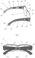
Figure 1 illustrates a perspective view of an eyewear frame according to the disclosure; -
Figures 2 illustrates a rear view of an eyewear frame according to the disclosure; and -
Figure 3 illustrates a perspective view of a motion pattern while carrying an eyewear frame according to the disclosure. - As illustrated on
Figure 1 the disclosure relates to aneyewear frame 10 comprising acentral portion 12, afirst temple 16a and asecond temple 16b. - The
central portion 12 is configured to receive at least one, for example two,optical lens optical lens 14acentral portion 12 may comprise a first ant asecond contour portions optical lenses second contour portions bridge portion 12c. The first and thesecond temples lateral ends central portion 12, thefirst temple 16a being pivotably fixed to the firstlateral end 22a and thesecond temple 16b being pivotably fixed to the secondlateral end 22b. - The
first temple 16a comprises a first embeddedelectronic device 18a and afirst battery 20a. The first embeddedelectronic device 18a comprises a first close-range communication system 24a and a first the medium-rangewireless communication system 28a. - The
second temple 16b comprises a second embeddedelectronic device 18b and asecond battery 20b. The second embeddedelectronic device 18b comprises a second close-range communication system 24b and a second the medium-rangewireless communication system 28b. - The
temples eyewear fame 10 comprises embeddedelectronic devices - In an embodiment, the first and the
second batteries second temples free ends end central portion 12. This arrangement enables a better balance of the eyewear frame, once worn by a wearer. - The first electronic and the second
electronic devices - The close-
range communication systems communications systems electronic devices temple range communication systems - In an embodiment, the close-
range communication systems range communication systems - The bitragion breadth corresponds to an average distance of 14,5 cm for men and 13, 8 cm for women. The bitragion breadth is the breadth of the head from the right tragion to the left. Tragion is the cartilaginous notch at the front of the ear. The first percentile corresponding to the minimal birtagion breadth is 13,1 cm for men and 12,5 cm for women.
- The maximal communication distance of close-
range communication systems temples temples temples temple central portion 12. - With respect to the open position, a closed position is defined by the
temples central portion 12. The free end of eachtemple central portion 12, and the temples are in contact or quasi-contact, being spaced by at most few millimeters, for example 5 millimeters. - In an embodiment, the
electronic devices range communication systems electronic devices electronic devices electronic devices range communication systems electronic devices range communication systems electronic devices wireless communication system range communication systems wireless communication system - In an embodiment, the first and the second
electronic devices wireless communication system range communication systems wireless communication system wireless communication system devices wireless communication system range communication systems range communication systems wireless communication system - In a preferred embodiment, the medium-range
wireless communication systems - In an embodiment, the close-
range communication systems - to pair the first and second
electronic devices - to define among the first or second
electronic devices wireless communication systems - In an embodiment, the eyewear frame comprises a communication activation device, embedded in each of the
temple range communication systems range communication systems temples central portion 12 of the frame and/or performing a specific motion pattern holding the frame and/or charging of at least the first and/or thesecond battery - The communication activation device, upon detection of one of the activation event, enables the close-
range communications systems range communication systems range communication systems electronic devices range communication systems - In an embodiment, the communication activation device comprises at least one motion sensor, the motion sensor is configured to activate close-range radio frequency-based
communication systems figure 3 ). The motion sensor may be an accelerometer, a gyroscope, or any passive/ active motion sensor able to recognize a motion pattern. - In an embodiment, the communication activation device comprises at least one battery sensor, the battery sensor is configured to activate close-range radio frequency-based
communication systems second batteries - The disclosure further relates to a method for synchronizing embedded
electronic devices eyewear frame 10 comprising: - a
central portion 12 configured to receive at least oneoptical lens - a
first temple 16a having a first embeddedelectronic device 18a and afirst battery 20a, - a
second temple 16b having a second embeddedelectronic device 18b and asecond battery 20b, - the
first temple 16a is pivotably fixed to afirst end 22a of thecentral portion 12 andsecond temple 16b is pivotably fixed to asecond end 22b of thecentral portion 12, - the first electronic and the second
electronic devices - the first and second
electronic devices range communication system - wherein the method comprises:
- activating the close-
range communication systems - exchanging identifiers of the first and second
electronic devices range communication systems - synchronizing the first and second electronic devices18a, 18b.
- activating the close-
- Advantageously, the method provides a simple and secure way to sync the
electronic devices temples - In an embodiment, activating the close-
range communication systems motion pattern 30 by a motion sensor. - In an embodiment, upon synchronizing the first and second
electronic devices electronic devices - Prior to allowing each
electronic device wireless communication system 28a of the firstelectronic device 18a and the second medium-rangewireless communication system 28b of the secondelectronic device 18b must know each other's identifiers. - In the case of two medium-range
wireless communication systems - The solution proposed here is a method that allows for both first and second
electronic devices - The embedded first and second
electronic devices range communication systems electronic devices range communication systems range communication systems - The medium-range
wireless communication systems range communication systems - The identifiers exchanged between the close-
range communication systems 24a, may be the MAC address of the embeddedelectronic devices range communication systems wireless communication systems electronic devices - In order to start the method of the disclosure, a person may just rotate each
temple eyewear frame 10 towards the central portion 12 (shown infigure 2 ). This rotating movement of thetemples central portion 12 of theeyewear frame 10 may be referred to as closing thetemples temples eyewear frame 10 to activate the close-range communication systems temple eyewear frame 10 that a motion sensor such as a gyroscope or an accelerometer may sense. - Alternatively, the communication activation device may be configured to activate the close-
range communication systems second battery - In order to avoid random synchronization of the first and second
electronic devices temples central portion 12, are closed and that amotion pattern 30 is performed, for example, by the person holding theeyewear frame 10. A double activation step may be required to enable the communication the close-range communication systems - closing each
temple central portion 12 and reproducing amotion pattern 30, and/or - closing each
temple central portion 12 and charging at least one of the first and thesecond batteries - Having a particular multi-processing method makes pairing between
electronic devices electronic devices eyewear frame 10 during the manufacturing and assembly steps. - The NFC identifiers exchange requires that both
temples range communication systems second temples temples temples range communication systems 24a, 24b. Said closing and stacking enable the first andsecond temples range communication systems 24a, 24b. Said stacking and centering enable to shorten the distance between the two close-range communication systems - The communication between the close-
range communication systems range communication systems range communication devices - Another way to activate the synchronization of the first and second
electronic devices - In an embodiment, the eyewear frame also embeds at least one human machine interface such as at least one button. The at least one button type may be mechanical or capacitive or magnetic. After closing the first and
second temples 16a, 16, the first and secondelectronic device second temples - Such simple temples synchronization methods ease the replacement of at least one
temple eyewear frame 10 while still enabling the synchronization of theelectronic device temple - After each temple replacement, the
electronic devices eyewear frame 10 is working properly. - In a preferred embodiment, the communication between the close-
range communication systems - In an embodiment, to limit power consumption, the close-range communication exchange is only allowed when both embed
electronic devices - Close-
range communication systems electronic devices - At a first boot, neither the first nor second
electronic devices electronic device - Every first and second
electronic devices second temples electronic devices - In an embodiment, the Bluetooth Low Energy® slave or master role may be pre-defined into the firmware, but this means that for example each right temple would be the master and left temple would be the slave. In another embodiment, each left temple would be the master and right temple would be the slave. The self-determination of the Bluetooth Low Energy® role over the
electronic devices eyewear frame 10 and more precisely the first andsecond temples - Alternatively the medium-range
wireless communication systems wireless communication systems range communication systems - Once identifiers exchange is performed by the close-
range communication systems electronic device range communication systems electronic devices electronic devices electronic devices 18a, 18, the close-range communication devices range communication devices wireless communication systems range communication systems - Once the first and second
electronic devices eyewear frame 10 is switched on, the eyewear frame usage is free oftemples electronic devices electronic devices - The active communication between both medium-range
wireless communication systems temples batteries batteries eyewear frame 10 on/off status, or exchange of data related to their sensors, or related to their actuators. - In an embodiment, the embedded
electronic devices electronic devices - The invention has been described above with the aid of embodiments without limitation of the general inventive concept. Many further modifications and variations will be apparent to those skilled in the art upon making reference to the foregoing illustrative embodiments, which are given by way of example only and which are not intended to limit the scope of the invention, that being determined solely by the appended claims.
- In the claims, the word "comprising" does not exclude other elements or steps, and the indefinite article "a" or "an" does not exclude a plurality. The mere fact that different features are recited in mutually different dependent claims does not indicate that a combination of these features cannot be advantageously used. Any reference signs in the claims should not be construed as limiting the scope of the invention.
Claims (14)
- An eyewear frame (10) comprising:- a central portion (12) configured to receive at least one optical lens (14a, 14 b),- a first temple (16a) having a first embedded electronic device (18a) and a first battery (20a),- a second temple (16b) having a second embedded electronic device (18b) and a second battery (20b),the first temple (16a) is pivotably fixed to a first end (22a) of the central portion (12) and the second temple (16b) is pivotably fixed to a second end (22b) of the central portion (12),wherein the first electronic and the second electronic devices (18a, 18b) are configured to communicate in a wireless manner when the temples (16a, 16b) are in an opened position,the first and second electronic devices (18a, 18b) comprise each a close-range communication system (24a, 24b) configured to synchronize the first and the second electronic devices (18a, 18b) when the temples (16a,16b) are spaced at most a few millimetres apart, andwherein the eyewear frame (10) comprises a communication activation device configured to activate the close-range communication systems (24a, 24b).
- Eyewear frame according to claims 1, wherein the close-range communication systems (24a, 24b) are radio frequency-based communication systems, for example using a NFC communication protocol.
- Eyewear frame according to claim 1 or 2, wherein the electronic devices (18a, 18b) synchronization, via the close-range communication systems (24a, 24b), is based on the first and second electronic devices (18a, 18b) identities, for example at least a part of MAC address or an unique identifier defining respectively the first and second electronic devices (18a, 18b).
- Eyewear frame according to any of the preceding claims, wherein the first and the second electronic devices (18a, 18b) further comprise respectively a medium-range wireless communication system (28a, 28b).
- Eyewear frame according to claim 4, wherein the medium-range wireless communication systems (28a, 28b) comprise each Near-Field Magnetic Induction Communication or radio frequency communication, for example based on the Bluetooth® communication protocol.
- Eyewear frame according to any of the preceding claims, wherein the close-range communication systems (24a, 24b) are configured:- to pair the first and second electronic devices (18a, 18b), and- to define among the first or second electronic devices (18a, 18b) a master and a slave used for the medium-range wireless communication systems (28a, 28b).
- Eyewear frame according to any of any of the preceding claims, wherein the communication activation device comprises at least one motion sensor, the motion sensor is configured to activate close-range radio frequency-based communication systems (24a, 24b) upon detection of a specific motion pattern (30).
- Eyewear frame according to any of any of the preceding claims, wherein the communication activation device comprises at least one battery sensor, the battery sensor is configured to activate close-range radio frequency-based communication systems (24a, 24b) upon detection of a charge of at least one, preferably both, of the first and second batteries (20a, 20b).
- Eyewear frame according to any of the preceding claims, wherein the communication activation device comprises at least one capacitive or physical button, the capacitive or physical button is configured to activate close-range radio frequency-based communication systems (24a, 24b) upon contact of the capacitive button or pressure of the physical button.
- Method for synchronizing embedded electronic devices (18a, 18b) of an eyewear frame (10) comprising:- a central portion (12) configured to receive at least one optical lens (14a, 14b),- a first temple (16a) having a first embedded electronic device (18a) and a first battery (20a),- a second temple (16b) having a second embedded electronic device (18b) and a second battery (20b),- a communication activation device,the first temple (16a) is pivotably fixed to a first end (22a) of the central portion (12) and second temple (16b) is pivotably fixed to a second end (22b) of the central portion (12),the first electronic and the second electronic devices (18a, 18b) are configured to communicate in a wireless manner when the temples (16a, 16b) are in an opened position,the first and second electronic devices (18a, 18b) comprise each a close-range communication system (24a, 24b),wherein the method comprises:- determining by the communication activation device an occurrence of an activation event,- activating, by the activation device, the close-range communication systems (24a, 24b),- exchanging identifiers of the first and second electronic devices (18a, 18b) via the close-range communication systems (24a, 24b) when the temples (16a,16b) are spaced at most a few millimetres apart, and- synchronizing the first and second electronic devices (18a, 18b).
- Method according to claim 10, wherein activating the close-range communication systems (24a, 24b) is caused at least by the detection of a motion pattern (30) by a motion sensor.
- Method according to claim 10 or 11, wherein activating the close-range communication systems (24a, 24b) is caused at least by a detection of the charge of the first and/or second battery (20a, 20b).
- Method according to any of claims 10 to 12, wherein activating the close-range communication systems (24a, 24b) is caused at least by the contact of a capacitive button or the pressure of a physical button or the sensing of a magnet element.
- Method according to any of claims 10 to 13, wherein upon synchronizing the first and second electronic devices (18a, 18b) the method further comprises defining among the first or second electronic devices (18a, 18b) a master and a slave.
Applications Claiming Priority (2)
| Application Number | Priority Date | Filing Date | Title |
|---|---|---|---|
| EP20305512 | 2020-05-18 | ||
| PCT/EP2021/063124 WO2021233907A1 (en) | 2020-05-18 | 2021-05-18 | An eyewear frame |
Publications (2)
| Publication Number | Publication Date |
|---|---|
| EP4154057A1 EP4154057A1 (en) | 2023-03-29 |
| EP4154057B1 true EP4154057B1 (en) | 2025-07-02 |
Family
ID=71465233
Family Applications (1)
| Application Number | Title | Priority Date | Filing Date |
|---|---|---|---|
| EP21727426.5A Active EP4154057B1 (en) | 2020-05-18 | 2021-05-18 | An eyewear frame |
Country Status (5)
| Country | Link |
|---|---|
| US (1) | US12591150B2 (en) |
| EP (1) | EP4154057B1 (en) |
| CN (1) | CN115427873B (en) |
| BR (1) | BR112022019447A2 (en) |
| WO (1) | WO2021233907A1 (en) |
Families Citing this family (5)
| Publication number | Priority date | Publication date | Assignee | Title |
|---|---|---|---|---|
| US20250181862A1 (en) * | 2017-05-17 | 2025-06-05 | Renauld International, Inc. | Embedded keepsake for line-of-sight display with a scanning element for digital authentication and gateway. |
| CN114879364A (en) * | 2022-03-14 | 2022-08-09 | 奇点临近技术(上海)有限公司 | Intelligent glasses and display method |
| WO2024048937A1 (en) * | 2022-09-01 | 2024-03-07 | 삼성전자주식회사 | Wearable electronic device and charging system comprising same |
| CN115498290B (en) * | 2022-09-15 | 2025-08-01 | 湖北星纪魅族科技有限公司 | Charging method of intelligent wearable device, storage medium, device and wearable device |
| WO2025085570A1 (en) * | 2023-10-20 | 2025-04-24 | Alphamicron Incorporated | Electronic eyewear system with internal wireless communication |
Family Cites Families (30)
| Publication number | Priority date | Publication date | Assignee | Title |
|---|---|---|---|---|
| JP4172120B2 (en) * | 1999-06-29 | 2008-10-29 | ソニー株式会社 | COMMUNICATION DEVICE AND COMMUNICATION METHOD, COMMUNICATION TERMINAL DEVICE |
| US11630331B2 (en) * | 2003-10-09 | 2023-04-18 | Ingeniospec, Llc | Eyewear with touch-sensitive input surface |
| CA2656267A1 (en) | 2006-06-23 | 2008-01-03 | Pixeloptics, Inc. | Electronic adapter for electro-active spectacle lenses |
| US10613355B2 (en) * | 2007-05-04 | 2020-04-07 | E-Vision, Llc | Moisture-resistant eye wear |
| BRPI1007206A2 (en) * | 2009-01-09 | 2016-02-23 | Pixeloptics Inc | electro-active glasses and associated electronics |
| KR101745411B1 (en) * | 2009-02-13 | 2017-06-09 | 위트리시티 코포레이션 | Wireless energy transfer in lossy environments |
| US20110068892A1 (en) * | 2009-09-20 | 2011-03-24 | Awarepoint Corporation | Wireless Tracking System And Method Utilizing Near-Field Communication Devices |
| US8867993B1 (en) * | 2009-09-20 | 2014-10-21 | Awarepoint Corporation | Wireless tracking system and method utilizing near-field communication devices |
| US8432260B2 (en) | 2010-02-26 | 2013-04-30 | GM Global Technology Operations LLC | Simplified vehicle bluetooth pairing employing near field communication tags |
| US8964298B2 (en) * | 2010-02-28 | 2015-02-24 | Microsoft Corporation | Video display modification based on sensor input for a see-through near-to-eye display |
| US12436411B2 (en) * | 2010-07-02 | 2025-10-07 | E-Vision Optics, Llc | Moisture-resistant eye wear |
| US8868500B2 (en) * | 2011-01-14 | 2014-10-21 | Apple Inc. | Data synchronization |
| EP2739055A4 (en) * | 2011-07-29 | 2015-09-09 | Samsung Electronics Co Ltd | METHOD FOR SYNCHRONIZING DISPLAY DEVICE, METHOD FOR SYNCHRONIZING GLASSES, AND METHOD FOR SYNCHRONIZING DISPLAY DEVICE WITH GLASSES |
| CN108014002A (en) * | 2011-11-04 | 2018-05-11 | 马萨诸塞眼科耳科诊所 | Self-adaptive visual auxiliary device |
| WO2016015209A1 (en) | 2014-07-28 | 2016-02-04 | 华为技术有限公司 | Bluetooth communication method and device |
| US9998848B2 (en) | 2014-11-15 | 2018-06-12 | Abhishek Adhikari | System and method for making a quick connection between a smart mobile device and external audio speakers and video monitors using a connector pad |
| US9785261B2 (en) * | 2014-12-19 | 2017-10-10 | Intel Corporation | Near field communications (NFC)-based active stylus |
| US9977245B2 (en) * | 2015-02-27 | 2018-05-22 | LAFORGE Optical, Inc. | Augmented reality eyewear |
| WO2016168409A1 (en) | 2015-04-14 | 2016-10-20 | Capital One Services, LLC. | Automated bluetooth pairing |
| DE102015117172B4 (en) * | 2015-10-08 | 2023-05-04 | Infineon Technologies Ag | communication arrangement |
| US10302970B2 (en) * | 2015-12-14 | 2019-05-28 | Johnson & Johnson Vision Care, Inc. | Electronic ophthalmic lens with oscillator frequency adjustment |
| KR20180100329A (en) * | 2016-02-10 | 2018-09-10 | 미폰 벤쳐스 인코포레이티드 | User authentication and registration of wearable devices using biometrics |
| DE102016205830B4 (en) | 2016-04-07 | 2022-08-18 | Volkswagen Aktiengesellschaft | Bluetooth connection procedure and Bluetooth device |
| EP3299871A1 (en) * | 2016-09-22 | 2018-03-28 | Essilor International | A wearing detection module for spectacle frame |
| CN206096664U (en) * | 2016-09-26 | 2017-04-12 | 广州知途鸟智能科技有限公司 | Intelligence glasses and mirror leg subassembly thereof |
| US10218114B2 (en) * | 2016-10-12 | 2019-02-26 | Snap Inc. | Circuits and methods for wearable device charging and wired control |
| US9910298B1 (en) | 2017-04-17 | 2018-03-06 | Vision Service Plan | Systems and methods for a computerized temple for use with eyewear |
| US10534203B2 (en) * | 2017-07-31 | 2020-01-14 | Snap Inc. | Near-field antenna for eyewear |
| CN114222941B (en) * | 2019-08-15 | 2024-03-15 | 美国斯耐普公司 | Eyewear straps |
| US11297224B2 (en) * | 2019-09-30 | 2022-04-05 | Snap Inc. | Automated eyewear device sharing system |
-
2021
- 2021-05-18 US US17/997,606 patent/US12591150B2/en active Active
- 2021-05-18 WO PCT/EP2021/063124 patent/WO2021233907A1/en not_active Ceased
- 2021-05-18 EP EP21727426.5A patent/EP4154057B1/en active Active
- 2021-05-18 CN CN202180028507.6A patent/CN115427873B/en active Active
- 2021-05-18 BR BR112022019447A patent/BR112022019447A2/en not_active IP Right Cessation
Also Published As
| Publication number | Publication date |
|---|---|
| US20230221584A1 (en) | 2023-07-13 |
| CN115427873A (en) | 2022-12-02 |
| US12591150B2 (en) | 2026-03-31 |
| CN115427873B (en) | 2025-09-05 |
| EP4154057A1 (en) | 2023-03-29 |
| WO2021233907A1 (en) | 2021-11-25 |
| BR112022019447A2 (en) | 2022-12-13 |
Similar Documents
| Publication | Publication Date | Title |
|---|---|---|
| US12591150B2 (en) | Eyewear frame | |
| US12271056B2 (en) | Eyewear docking station and electronic module | |
| CN101479644B (en) | Electronic adapter for electro-active spectacle lenses | |
| US9229248B2 (en) | Electro-active spectacles and associated electronics | |
| US20130235328A1 (en) | Data exchange system | |
| CA3180624A1 (en) | Safety glasses | |
| CN104423066A (en) | Ophthalmic lens system capable of communication between lenses utilizing a secondary external device | |
| JP7002598B2 (en) | Glasses | |
| CN202026430U (en) | Novel stereoscopic television | |
| CN102955257A (en) | 3D glasses and 3D glasses radio frequency communication method | |
| HK1190465A (en) | Electro-active spectacles and associated electronics |
Legal Events
| Date | Code | Title | Description |
|---|---|---|---|
| STAA | Information on the status of an ep patent application or granted ep patent |
Free format text: STATUS: UNKNOWN |
|
| STAA | Information on the status of an ep patent application or granted ep patent |
Free format text: STATUS: THE INTERNATIONAL PUBLICATION HAS BEEN MADE |
|
| PUAI | Public reference made under article 153(3) epc to a published international application that has entered the european phase |
Free format text: ORIGINAL CODE: 0009012 |
|
| STAA | Information on the status of an ep patent application or granted ep patent |
Free format text: STATUS: REQUEST FOR EXAMINATION WAS MADE |
|
| 17P | Request for examination filed |
Effective date: 20220926 |
|
| AK | Designated contracting states |
Kind code of ref document: A1 Designated state(s): AL AT BE BG CH CY CZ DE DK EE ES FI FR GB GR HR HU IE IS IT LI LT LU LV MC MK MT NL NO PL PT RO RS SE SI SK SM TR |
|
| P01 | Opt-out of the competence of the unified patent court (upc) registered |
Effective date: 20230525 |
|
| DAV | Request for validation of the european patent (deleted) | ||
| DAX | Request for extension of the european patent (deleted) | ||
| REG | Reference to a national code |
Ref legal event code: R079 Free format text: PREVIOUS MAIN CLASS: G02C0011000000 Ref country code: DE Ref legal event code: R079 Ref document number: 602021033344 Country of ref document: DE Free format text: PREVIOUS MAIN CLASS: G02C0011000000 Ipc: H04B0005240000 |
|
| GRAP | Despatch of communication of intention to grant a patent |
Free format text: ORIGINAL CODE: EPIDOSNIGR1 |
|
| STAA | Information on the status of an ep patent application or granted ep patent |
Free format text: STATUS: GRANT OF PATENT IS INTENDED |
|
| RIC1 | Information provided on ipc code assigned before grant |
Ipc: H04B 1/3827 20150101ALI20250210BHEP Ipc: G02C 11/00 20060101ALI20250210BHEP Ipc: H04B 5/24 20240101AFI20250210BHEP |
|
| INTG | Intention to grant announced |
Effective date: 20250313 |
|
| GRAS | Grant fee paid |
Free format text: ORIGINAL CODE: EPIDOSNIGR3 |
|
| GRAA | (expected) grant |
Free format text: ORIGINAL CODE: 0009210 |
|
| STAA | Information on the status of an ep patent application or granted ep patent |
Free format text: STATUS: THE PATENT HAS BEEN GRANTED |
|
| AK | Designated contracting states |
Kind code of ref document: B1 Designated state(s): AL AT BE BG CH CY CZ DE DK EE ES FI FR GB GR HR HU IE IS IT LI LT LU LV MC MK MT NL NO PL PT RO RS SE SI SK SM TR |
|
| REG | Reference to a national code |
Ref country code: GB Ref legal event code: FG4D |
|
| REG | Reference to a national code |
Ref country code: CH Ref legal event code: EP |
|
| REG | Reference to a national code |
Ref country code: DE Ref legal event code: R096 Ref document number: 602021033344 Country of ref document: DE |
|
| REG | Reference to a national code |
Ref country code: IE Ref legal event code: FG4D |
|
| REG | Reference to a national code |
Ref country code: NL Ref legal event code: MP Effective date: 20250702 |
|
| PG25 | Lapsed in a contracting state [announced via postgrant information from national office to epo] |
Ref country code: PT Free format text: LAPSE BECAUSE OF FAILURE TO SUBMIT A TRANSLATION OF THE DESCRIPTION OR TO PAY THE FEE WITHIN THE PRESCRIBED TIME-LIMIT Effective date: 20251103 |
|
| PG25 | Lapsed in a contracting state [announced via postgrant information from national office to epo] |
Ref country code: NL Free format text: LAPSE BECAUSE OF FAILURE TO SUBMIT A TRANSLATION OF THE DESCRIPTION OR TO PAY THE FEE WITHIN THE PRESCRIBED TIME-LIMIT Effective date: 20250702 |
|
| REG | Reference to a national code |
Ref country code: AT Ref legal event code: MK05 Ref document number: 1810467 Country of ref document: AT Kind code of ref document: T Effective date: 20250702 |
|
| PG25 | Lapsed in a contracting state [announced via postgrant information from national office to epo] |
Ref country code: IS Free format text: LAPSE BECAUSE OF FAILURE TO SUBMIT A TRANSLATION OF THE DESCRIPTION OR TO PAY THE FEE WITHIN THE PRESCRIBED TIME-LIMIT Effective date: 20251102 |
|
| PG25 | Lapsed in a contracting state [announced via postgrant information from national office to epo] |
Ref country code: NO Free format text: LAPSE BECAUSE OF FAILURE TO SUBMIT A TRANSLATION OF THE DESCRIPTION OR TO PAY THE FEE WITHIN THE PRESCRIBED TIME-LIMIT Effective date: 20251002 |
|
| REG | Reference to a national code |
Ref country code: LT Ref legal event code: MG9D |
|
| PG25 | Lapsed in a contracting state [announced via postgrant information from national office to epo] |
Ref country code: AT Free format text: LAPSE BECAUSE OF FAILURE TO SUBMIT A TRANSLATION OF THE DESCRIPTION OR TO PAY THE FEE WITHIN THE PRESCRIBED TIME-LIMIT Effective date: 20250702 |
|
| PG25 | Lapsed in a contracting state [announced via postgrant information from national office to epo] |
Ref country code: FI Free format text: LAPSE BECAUSE OF FAILURE TO SUBMIT A TRANSLATION OF THE DESCRIPTION OR TO PAY THE FEE WITHIN THE PRESCRIBED TIME-LIMIT Effective date: 20250702 |
|
| PG25 | Lapsed in a contracting state [announced via postgrant information from national office to epo] |
Ref country code: HR Free format text: LAPSE BECAUSE OF FAILURE TO SUBMIT A TRANSLATION OF THE DESCRIPTION OR TO PAY THE FEE WITHIN THE PRESCRIBED TIME-LIMIT Effective date: 20250702 |
|
| PG25 | Lapsed in a contracting state [announced via postgrant information from national office to epo] |
Ref country code: GR Free format text: LAPSE BECAUSE OF FAILURE TO SUBMIT A TRANSLATION OF THE DESCRIPTION OR TO PAY THE FEE WITHIN THE PRESCRIBED TIME-LIMIT Effective date: 20251003 |
|
| PG25 | Lapsed in a contracting state [announced via postgrant information from national office to epo] |
Ref country code: CZ Free format text: LAPSE BECAUSE OF FAILURE TO SUBMIT A TRANSLATION OF THE DESCRIPTION OR TO PAY THE FEE WITHIN THE PRESCRIBED TIME-LIMIT Effective date: 20250702 Ref country code: SE Free format text: LAPSE BECAUSE OF FAILURE TO SUBMIT A TRANSLATION OF THE DESCRIPTION OR TO PAY THE FEE WITHIN THE PRESCRIBED TIME-LIMIT Effective date: 20250702 |
|
| PG25 | Lapsed in a contracting state [announced via postgrant information from national office to epo] |
Ref country code: LV Free format text: LAPSE BECAUSE OF FAILURE TO SUBMIT A TRANSLATION OF THE DESCRIPTION OR TO PAY THE FEE WITHIN THE PRESCRIBED TIME-LIMIT Effective date: 20250702 |
|
| PG25 | Lapsed in a contracting state [announced via postgrant information from national office to epo] |
Ref country code: PL Free format text: LAPSE BECAUSE OF FAILURE TO SUBMIT A TRANSLATION OF THE DESCRIPTION OR TO PAY THE FEE WITHIN THE PRESCRIBED TIME-LIMIT Effective date: 20250702 Ref country code: BG Free format text: LAPSE BECAUSE OF FAILURE TO SUBMIT A TRANSLATION OF THE DESCRIPTION OR TO PAY THE FEE WITHIN THE PRESCRIBED TIME-LIMIT Effective date: 20250702 |
|
| PG25 | Lapsed in a contracting state [announced via postgrant information from national office to epo] |
Ref country code: RS Free format text: LAPSE BECAUSE OF FAILURE TO SUBMIT A TRANSLATION OF THE DESCRIPTION OR TO PAY THE FEE WITHIN THE PRESCRIBED TIME-LIMIT Effective date: 20251002 |
|
| PG25 | Lapsed in a contracting state [announced via postgrant information from national office to epo] |
Ref country code: ES Free format text: LAPSE BECAUSE OF FAILURE TO SUBMIT A TRANSLATION OF THE DESCRIPTION OR TO PAY THE FEE WITHIN THE PRESCRIBED TIME-LIMIT Effective date: 20250702 |
|
| PG25 | Lapsed in a contracting state [announced via postgrant information from national office to epo] |
Ref country code: SM Free format text: LAPSE BECAUSE OF FAILURE TO SUBMIT A TRANSLATION OF THE DESCRIPTION OR TO PAY THE FEE WITHIN THE PRESCRIBED TIME-LIMIT Effective date: 20250702 |
|
| PG25 | Lapsed in a contracting state [announced via postgrant information from national office to epo] |
Ref country code: DK Free format text: LAPSE BECAUSE OF FAILURE TO SUBMIT A TRANSLATION OF THE DESCRIPTION OR TO PAY THE FEE WITHIN THE PRESCRIBED TIME-LIMIT Effective date: 20250702 |
|
| PG25 | Lapsed in a contracting state [announced via postgrant information from national office to epo] |
Ref country code: SK Free format text: LAPSE BECAUSE OF FAILURE TO SUBMIT A TRANSLATION OF THE DESCRIPTION OR TO PAY THE FEE WITHIN THE PRESCRIBED TIME-LIMIT Effective date: 20250702 Ref country code: EE Free format text: LAPSE BECAUSE OF FAILURE TO SUBMIT A TRANSLATION OF THE DESCRIPTION OR TO PAY THE FEE WITHIN THE PRESCRIBED TIME-LIMIT Effective date: 20250702 |
|
| PLBE | No opposition filed within time limit |
Free format text: ORIGINAL CODE: 0009261 |
|
| STAA | Information on the status of an ep patent application or granted ep patent |
Free format text: STATUS: NO OPPOSITION FILED WITHIN TIME LIMIT |