EP4154019B1 - Mode localised accelerometer - Google Patents
Mode localised accelerometer Download PDFInfo
- Publication number
- EP4154019B1 EP4154019B1 EP21727529.6A EP21727529A EP4154019B1 EP 4154019 B1 EP4154019 B1 EP 4154019B1 EP 21727529 A EP21727529 A EP 21727529A EP 4154019 B1 EP4154019 B1 EP 4154019B1
- Authority
- EP
- European Patent Office
- Prior art keywords
- resonant
- resonant element
- accelerometer according
- frame
- elements
- Prior art date
- Legal status (The legal status is an assumption and is not a legal conclusion. Google has not performed a legal analysis and makes no representation as to the accuracy of the status listed.)
- Active
Links
Images


Classifications
-
- G—PHYSICS
- G01—MEASURING; TESTING
- G01P—MEASURING LINEAR OR ANGULAR SPEED, ACCELERATION, DECELERATION, OR SHOCK; INDICATING PRESENCE, ABSENCE, OR DIRECTION, OF MOVEMENT
- G01P15/00—Measuring acceleration; Measuring deceleration; Measuring shock, i.e. sudden change of acceleration
- G01P15/02—Measuring acceleration; Measuring deceleration; Measuring shock, i.e. sudden change of acceleration by making use of inertia forces using solid seismic masses
- G01P15/08—Measuring acceleration; Measuring deceleration; Measuring shock, i.e. sudden change of acceleration by making use of inertia forces using solid seismic masses with conversion into electric or magnetic values
- G01P15/097—Measuring acceleration; Measuring deceleration; Measuring shock, i.e. sudden change of acceleration by making use of inertia forces using solid seismic masses with conversion into electric or magnetic values by vibratory elements
-
- B—PERFORMING OPERATIONS; TRANSPORTING
- B81—MICROSTRUCTURAL TECHNOLOGY
- B81B—MICROSTRUCTURAL DEVICES OR SYSTEMS, e.g. MICROMECHANICAL DEVICES
- B81B5/00—Devices comprising elements which are movable in relation to each other, e.g. comprising slidable or rotatable elements
-
- G—PHYSICS
- G01—MEASURING; TESTING
- G01C—MEASURING DISTANCES, LEVELS OR BEARINGS; SURVEYING; NAVIGATION; GYROSCOPIC INSTRUMENTS; PHOTOGRAMMETRY OR VIDEOGRAMMETRY
- G01C19/00—Gyroscopes; Turn-sensitive devices using vibrating masses; Turn-sensitive devices without moving masses; Measuring angular rate using gyroscopic effects
- G01C19/56—Turn-sensitive devices using vibrating masses, e.g. vibratory angular rate sensors based on Coriolis forces
-
- G—PHYSICS
- G01—MEASURING; TESTING
- G01P—MEASURING LINEAR OR ANGULAR SPEED, ACCELERATION, DECELERATION, OR SHOCK; INDICATING PRESENCE, ABSENCE, OR DIRECTION, OF MOVEMENT
- G01P15/00—Measuring acceleration; Measuring deceleration; Measuring shock, i.e. sudden change of acceleration
- G01P15/02—Measuring acceleration; Measuring deceleration; Measuring shock, i.e. sudden change of acceleration by making use of inertia forces using solid seismic masses
- G01P15/08—Measuring acceleration; Measuring deceleration; Measuring shock, i.e. sudden change of acceleration by making use of inertia forces using solid seismic masses with conversion into electric or magnetic values
- G01P15/13—Measuring acceleration; Measuring deceleration; Measuring shock, i.e. sudden change of acceleration by making use of inertia forces using solid seismic masses with conversion into electric or magnetic values by measuring the force required to restore a proofmass subjected to inertial forces to a null position
-
- G—PHYSICS
- G01—MEASURING; TESTING
- G01P—MEASURING LINEAR OR ANGULAR SPEED, ACCELERATION, DECELERATION, OR SHOCK; INDICATING PRESENCE, ABSENCE, OR DIRECTION, OF MOVEMENT
- G01P15/00—Measuring acceleration; Measuring deceleration; Measuring shock, i.e. sudden change of acceleration
- G01P15/02—Measuring acceleration; Measuring deceleration; Measuring shock, i.e. sudden change of acceleration by making use of inertia forces using solid seismic masses
- G01P15/08—Measuring acceleration; Measuring deceleration; Measuring shock, i.e. sudden change of acceleration by making use of inertia forces using solid seismic masses with conversion into electric or magnetic values
- G01P2015/0805—Measuring acceleration; Measuring deceleration; Measuring shock, i.e. sudden change of acceleration by making use of inertia forces using solid seismic masses with conversion into electric or magnetic values being provided with a particular type of spring-mass-system for defining the displacement of a seismic mass due to an external acceleration
- G01P2015/0808—Measuring acceleration; Measuring deceleration; Measuring shock, i.e. sudden change of acceleration by making use of inertia forces using solid seismic masses with conversion into electric or magnetic values being provided with a particular type of spring-mass-system for defining the displacement of a seismic mass due to an external acceleration for defining in-plane movement of the mass, i.e. movement of the mass in the plane of the substrate
- G01P2015/0811—Measuring acceleration; Measuring deceleration; Measuring shock, i.e. sudden change of acceleration by making use of inertia forces using solid seismic masses with conversion into electric or magnetic values being provided with a particular type of spring-mass-system for defining the displacement of a seismic mass due to an external acceleration for defining in-plane movement of the mass, i.e. movement of the mass in the plane of the substrate for one single degree of freedom of movement of the mass
- G01P2015/0814—Measuring acceleration; Measuring deceleration; Measuring shock, i.e. sudden change of acceleration by making use of inertia forces using solid seismic masses with conversion into electric or magnetic values being provided with a particular type of spring-mass-system for defining the displacement of a seismic mass due to an external acceleration for defining in-plane movement of the mass, i.e. movement of the mass in the plane of the substrate for one single degree of freedom of movement of the mass for translational movement of the mass, e.g. shuttle type
Definitions
- the invention relates to accelerometers.
- the invention relates to accelerometer designs that are highly sensitive to small changes in acceleration and can be used as gravimeters.
- a resonant sensor is an oscillator whose output resonant frequency is a function of an input measurand.
- the output of a resonant sensor corresponds to the shift in resonant frequency of a mechanical microstructure that gets tuned in accordance with a change in a physical quantity to be measured.
- Resonant micro-accelerometers fabricated using silicon micromachining techniques present a number of significant advantages, the biggest being economy. These silicon resonant micro-accelerometers not only boast improved sensitivity and resolution relative to their more traditional capacitive detection based counterparts with similar device footprints, but have also been shown to provide enhanced dynamic range making them ideal candidates for potential application in numerous motion sensing applications within the identified markets.
- One potential sensing application is gravimetry.
- Resonant accelerometers can be designed to provide a low-noise response for near-DC measurements (suitable for applications in gravimetry) and a wide dynamic range enabling measurements over the entire +/-1g regime.
- WO2018/197857 A1 discloses a resonant sensor comprising a substrate and a proof mass suspended from the substrate by one or more flexures to allow the proof mass to move relative to the frame along a sensitive axis.
- First and second resonant elements are connected between the frame and the proof mass.
- Drive and sensing circuitry is configured to drive the first resonant element in a first mode, drive the second resonant element in a second mode different to the first mode, and determine a measure of acceleration.
- WO 2016/122960 A1 discloses a MEMS sensor that comprises a substrate and an anchor region coupled to the substrate. At least one support arm is coupled to the anchor region, at least two guiding arms are coupled to the at least one support arm, and a plurality of sensing elements are disposed on the at least two guiding arms to measure motion of the at least two guiding arms relative to the substrate.
- a proof mass system comprising at least one mass is coupled to each of the at least two guiding arms by a set of springs. The proof mass system is disposed outside the anchor region, the at least one support arm, the at least two guiding arms, the set of springs, and the plurality of sensing elements.
- an accelerometer according to claim 1 is provided.
- Other embodiments are covered by the dependent claims.
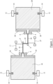
- FIG 1 is a schematic illustration of a top view of an accelerometer in accordance with the present invention.
- the accelerometer is advantageously fabricated entirely from a single semiconductor wafer, such as a silicon-on-insulator (SOI) wafer.
- SOI silicon-on-insulator
- the accelerometer comprises a first proof mass 10 and a second proof mass 20.
- the first proof mass is suspended from a frame 12 by flexures 14 so as to allow movement of the first proof mass along an axis, towards and away from the second proof mass.
- the second proof mass 20 is suspended from the frame 12 by flexures 14 in the same way, so as to allow movement of the second proof mass along the same axis, towards and away from the first proof mass.
- the axis is the sensitive axis of the accelerometer.
- a first resonant element 16 is connected between an anchor 8 and the first proof mass 10.
- the anchor 8 is part of the frame 12.
- the first resonant element extends along the sensitive axis.
- the first resonant element 16 is connected to the first proof mass 10 through amplifying levers 18.
- the amplifying levers 18 are fixed to the frame at pivot points 6.
- a second resonant element 26, identical to the first resonant element 16, is connected between a second anchor 8 and the second proof mass 20.
- the second proof mass is also identical to first proof mass, and the force amplifying levers 28 are identical to the force amplifying levers 18.
- the second resonant element extends along the same sensitive axis as the first resonant element, but in an opposite direction. This means that when the accelerometer undergoes an acceleration, the second resonant element 26 experiences an equal but opposite strain to the first resonant element 16.
- the first and second resonant elements 16, 26 are coupled by a coupling beam 22.
- the coupling beam 22 is a simple linear beam.
- the coupling beam is formed from the same silicon wafer as the resonant elements.
- Energy can be transferred from one resonant element to the other through the coupling beam.
- energy can be localised more in one resonant element than the other. This phenomenon is often referred to as mode localisation.
- the amount of mode localisation is dependent on the degree to which the strain on the first and second resonant elements is different. So the relative amplitude of vibration of the first and second resonant elements can be used to provide a measure of acceleration experienced by the proof masses. In fact, measuring amplitude variations induced by mode localisation provides a high resolution determination of acceleration that is relatively insensitive to environmental variation. This is described fully in WO2011/148137 .
- the coupling must therefore be non-zero and sufficient for each resonant mode to be resolvable from each other. In other words the coupling must be strong enough that there is no modal overlap in the coupled response of the system. In order to ensure the structure is robust and can be consistently produced, the coupling beam needs to have sufficient thickness.
- the coupling beam between the first and second resonant element is positioned close to the anchors 8. Positioning the coupling beam 22 closer to a node of the mode of vibration in use reduces the strength of coupling when compared to positioning the coupling beam closer to anti-node of the mode of vibration, and so increases the scale factor of the accelerometer.
- the coupling between the first and second resonant element can be achieved electrostatically instead of by a coupling beam. If a mechanical linkage is used, other shapes of beam are possible, as described with reference to Figure 5 below.
- third and fourth resonant elements are shown in dotted line.
- the third resonant element 17 is coupled to the first resonant element 16 by a mechanical linkage.
- the fourth resonant element 27 is coupled to the second resonant element 26 by a mechanical linkage.
- the third and fourth resonant elements are structurally identical to one another (and may be identical to the first and second resonant elements), and are coupled to the frame, but they are not coupled to either of the proof masses. The provision of further coupled resonant elements in this manner can enhance mode localisation and thereby improve the sensitivity of the measurement.
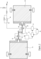
- Figure 2 illustrates an arrangement for driving the resonant elements of Figure 1 and for providing an output measure of acceleration.
- third and fourth resonant elements are not provided.
- the first and second resonant elements 16 and 26 are driven by an AC voltage signal from two separate drive electrodes 34 and 38. The same AC signal is applied to each drive electrode. The amplitude of oscillation of the first resonant element 16 is maintained at a constant level by sensing off electrode 36. The output from electrode 36 is fed into a control circuit, and the output of the control circuit fed back to drive electrodes 34 and 38.
- the first stage of the control circuit is a gain element 33 that provides a fairly large initial gain before feeding the signal into a variable gain amplifier (VGA) 35.
- the VGA 35 consists of an amplifier that adjusts its gain in accordance to a control signal (from an automatic gain control (AGC) circuit 39) and feeds the output to a buffer 37.
- AGC automatic gain control
- the AGC 39 consists of a circuit that detects the output of the first stage gain element using a peak detector (that compares the peak amplitude of the output arising from the first gain stage with that of a reference signal) and accordingly controls the gain of the first stage gain element to maintain the output at a constant peak amplitude.
- the controlled output signal from the buffer 37 is, in turn, used to drive the resonant elements in the chosen mode of oscillation.
- the modal amplitudes of the second resonant element (at the resonant mode wherein the oscillations are sustained) is then read out from sense electrode 40.
- Sensing of the amplitude of vibration may be implemented in several ways.
- the sensing of the amplitude of vibration of the first and second resonant elements may be achieved by measuring the motional current of the resonant elements as they oscillate from the sensing electrodes 36 and 40 respectively. Silicon also exhibits a strong piezoresistive effect, so the resistance of a silicon resonant element will change as it oscillates which may also be used as an alternative readout mechanism.
- the sensing means may comprise electrodes mounted adjacent to the first and second resonant elements to allow for capacitive sensing. Other possibilities for the sensing means include optical sensing of the oscillation of the first resonant element or even electro-magnetic transduction.
- the output from the sense electrode 40 is fed into a trans-resistance amplifier circuit 42 to convert the current signal from electrode 40 into a voltage signal that may be used to directly calculate an amplified measure of the modal amplitude variation of the second resonant element 26, from which any induced changes in the stiffness of the first resonant element 1 may be evaluated. From the change in stiffness, acceleration can be determined.
- the drive and sense arrangement can be extended, for instance by driving only the first and second resonant elements and sensing the response of all the resonant elements.
- all of the coupled resonant elements can be driven and sensed. Any number of coupled resonant elements can be used.
- FIG. 3 is a flow diagram, illustrating the steps carried out in a method in accordance with the present invention using an accelerometer of the type described above with reference to Figures 1 and 2 .
- the resonant elements are caused to vibrate in a resonant mode using a drive signal.
- the drive signal may comprise an AC voltage applied to the resonant elements and a DC biasing voltage applied to adjacent electrodes.
- the amplitude of vibration of the first resonant element is detected.
- the drive signal is adjusted to maintain the amplitude of the first resonant element at a constant level using a feedback loop.
- the amplitude of vibration of the second resonant element is detected in step 56 to provide a measure of the change in effective stiffness of the first resonant element, from which the acceleration or angular velocity of the proof mass along the axis of sensitivity can be determined in step 58.
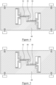
- Figures 4, 5 and 6 illustrate further embodiments that are variations of the accelerometer of Figures 1 and 2 .
- a single proof mass 60 is used instead of separate first and second proof masses 10 and 20.
- the single proof mass is connected to both the first resonant element 16 and the second resonant element 26.
- the first and second proof masses of Figure 1 are joined together and surround the first resonant element 16, second resonant element 26 and coupling beam 22.
- This arrangement operates in exactly the same way as the embodiment of Figure 1 , but allows the mass of the proof mass to be maximised for a given footprint of the accelerometer.
- the embodiment of Figure 5 is identical to the embodiment of Figure 4 except for the form of the coupling beam between the first and second resonant elements.
- the coupling beam 22 is a serpentine shaped beam.
- the coupling strength provided by a serpentine shaped beam can be less sensitive to temperature fluctuations than a simple linear beam and therefore can result in better common mode rejection of noise due to temperature variations.
- the embodiment of Figure 6 is identical to the embodiment of Figure 4 except for manner in which the coupling between the first and second resonant elements is provided.
- the first and second resonant elements 16, 26 are arranged coaxially along the sensitive axis of the accelerometer and coupling between them is provided by a non-ideal anchor 70.
- a separate coupling beam is not required.
- This arrangement has the advantage that the sensing axis of the two resonant elements are not offset from one another. It also has the advantage that impact of temperature fluctuations on a coupling beam are removed. However, it can be difficult to achieve a consistent level of coupling between the resonant elements from one device to the next in a manufacturing process.
- the first and second resonant elements 16, 26 may take the form of a simple clamped-clamped beam, as illustrated in Figure 7a or may take the form of a double ended tuning fork (DETF) as shown in Figure 7b .
- DETF tuning fork
- Different modal shapes for the two types of resonant element are illustrated in dotted line in Figure 7 .
- An accelerometer as described can be used for many applications.
- One example is as a gravimeter.
- a gravimeter can be used for surveying in oil or gas extraction.
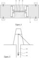
- Figure 10 illustrates a gravimeter down a bore hole. Measurements of the gravity field down a borehole can provide information about the density of the surrounding layers and so information about the presence of oil or gas reserves and their size and location. This requires measurement of gravitational filed in three dimensions.
- an accelerometer 80 in accordance with the invention is positioned within a borehole tool 82. The borehole tool is placed in the bore 84, suspended from a suitable structure on the surface.
- Gravimeters of this sort can be used in other applications, such as carbon storage monitoring, monitoring groundwater depletion, discovery of underwater aquifers, monitoring other processes underpinning the hydrological cycle, early-warning systems for earthquake-prone zones or for areas impacted by volcanic activity.
Landscapes
- Physics & Mathematics (AREA)
- General Physics & Mathematics (AREA)
- Engineering & Computer Science (AREA)
- Radar, Positioning & Navigation (AREA)
- Remote Sensing (AREA)
- Computer Hardware Design (AREA)
- Microelectronics & Electronic Packaging (AREA)
- Pressure Sensors (AREA)
- Geophysics And Detection Of Objects (AREA)
Description
- The invention relates to accelerometers. In particular, the invention relates to accelerometer designs that are highly sensitive to small changes in acceleration and can be used as gravimeters.
- A resonant sensor is an oscillator whose output resonant frequency is a function of an input measurand. In other words, the output of a resonant sensor corresponds to the shift in resonant frequency of a mechanical microstructure that gets tuned in accordance with a change in a physical quantity to be measured.
- There has been an increased interest over the past few years in the development of high precision micromachined 'all-silicon' resonant micro-accelerometers. This interest has been triggered due to the recent growth in demand for miniature high precision motion sensors within the aerospace, automotive and even the consumer-electronics markets. Resonant micro-accelerometers fabricated using silicon micromachining techniques present a number of significant advantages, the biggest being economy. These silicon resonant micro-accelerometers not only boast improved sensitivity and resolution relative to their more traditional capacitive detection based counterparts with similar device footprints, but have also been shown to provide enhanced dynamic range making them ideal candidates for potential application in numerous motion sensing applications within the identified markets. One potential sensing application is gravimetry. Resonant accelerometers can be designed to provide a low-noise response for near-DC measurements (suitable for applications in gravimetry) and a wide dynamic range enabling measurements over the entire +/-1g regime.
- Accelerometer designs that exploit mode localization between two or more weakly coupled resonators have been proposed. The variations in the eigenstates (which refer to the relative amplitudes at the resonant frequencies measured from each of the resonators) due to induced strain modulation one of the resonators, yields a measure of the inertial force on the sensor. Measuring such eigenstate variations induced by mode localization offers two key advantages over conventional resonant frequency shift based measurements: insensitivity to unwanted environmental variations; and orders of magnitude enhancement in the output sensitivity and consequently, the resolution of such sensors.
- It is an object of the present invention to provide a resonant accelerometer that provides the advantages of using mode localization but that has an improved scale factor when compared to previous designs.
-
WO2018/197857 A1 discloses a resonant sensor comprising a substrate and a proof mass suspended from the substrate by one or more flexures to allow the proof mass to move relative to the frame along a sensitive axis. First and second resonant elements are connected between the frame and the proof mass. Drive and sensing circuitry is configured to drive the first resonant element in a first mode, drive the second resonant element in a second mode different to the first mode, and determine a measure of acceleration. -
WO 2016/122960 A1 discloses a MEMS sensor that comprises a substrate and an anchor region coupled to the substrate. At least one support arm is coupled to the anchor region, at least two guiding arms are coupled to the at least one support arm, and a plurality of sensing elements are disposed on the at least two guiding arms to measure motion of the at least two guiding arms relative to the substrate. A proof mass system comprising at least one mass is coupled to each of the at least two guiding arms by a set of springs. The proof mass system is disposed outside the anchor region, the at least one support arm, the at least two guiding arms, the set of springs, and the plurality of sensing elements. - According to the invention an accelerometer according to claim 1 is provided. Other embodiments are covered by the dependent claims.
- Embodiments of the invention will now be described in detail, by way of example only, with reference to the accompanying drawings, in which:
-
Figure 1 is a schematic illustration of a first embodiment of the invention; -
Figure 2 illustrates drive and sensing circuitry for use with the embodiment ofFigure 1 ; -
Figure 3 is a flow diagram of the control process for the circuitry ofFigure 2 ; -
Figure 4 is a schematic illustration of a second embodiment of the invention; -
Figure 5 is a schematic illustration of a third embodiment of the invention; -
Figure 6 is a schematic illustration of a fourth embodiment of the invention; -
Figure 7 is a schematic illustration of resonant elements that can be used; and -
Figure 8 is a schematic illustration of a borehole tool including an accelerometer. -
Figure 1 is a schematic illustration of a top view of an accelerometer in accordance with the present invention. The accelerometer is advantageously fabricated entirely from a single semiconductor wafer, such as a silicon-on-insulator (SOI) wafer. - The accelerometer comprises a
first proof mass 10 and asecond proof mass 20. The first proof mass is suspended from aframe 12 byflexures 14 so as to allow movement of the first proof mass along an axis, towards and away from the second proof mass. Thesecond proof mass 20 is suspended from theframe 12 byflexures 14 in the same way, so as to allow movement of the second proof mass along the same axis, towards and away from the first proof mass. The axis is the sensitive axis of the accelerometer. - A first
resonant element 16 is connected between an anchor 8 and thefirst proof mass 10. The anchor 8 is part of theframe 12. The first resonant element extends along the sensitive axis. The firstresonant element 16 is connected to thefirst proof mass 10 through amplifyinglevers 18. The amplifyinglevers 18 are fixed to the frame atpivot points 6. - A second
resonant element 26, identical to the firstresonant element 16, is connected between a second anchor 8 and thesecond proof mass 20. The second proof mass is also identical to first proof mass, and theforce amplifying levers 28 are identical to the force amplifyinglevers 18. The second resonant element extends along the same sensitive axis as the first resonant element, but in an opposite direction. This means that when the accelerometer undergoes an acceleration, the secondresonant element 26 experiences an equal but opposite strain to the firstresonant element 16. - The first and second
resonant elements coupling beam 22. In this example thecoupling beam 22 is a simple linear beam. The coupling beam is formed from the same silicon wafer as the resonant elements. - Energy can be transferred from one resonant element to the other through the coupling beam. When the resonant elements experience opposite strain to one another, and so have different resonant properties, energy can be localised more in one resonant element than the other. This phenomenon is often referred to as mode localisation.
- The amount of mode localisation is dependent on the degree to which the strain on the first and second resonant elements is different. So the relative amplitude of vibration of the first and second resonant elements can be used to provide a measure of acceleration experienced by the proof masses. In fact, measuring amplitude variations induced by mode localisation provides a high resolution determination of acceleration that is relatively insensitive to environmental variation. This is described fully in
WO2011/148137 . - With the arrangement of
Figure 1 , because one resonant element undergoes compression while the other undergoes tension, a level of common mode rejection can be achieved using only a single pair of coupled resonant elements. This means that for a given size of accelerometer, the size, and hence mass, of the proof mass can greater than when two pairs of resonant elements are used to provide a differential output. Furthermore, locating the resonant element assembly at the centre of the structure allows for better matching between the two resonant elements, improving common mode rejection. - The weaker the coupling between the resonant elements the more pronounced the mode localisation and so the high resolution the measurement. However, the weaker the coupling is between the resonant elements the closer the resonant modes are in frequency. The coupling must therefore be non-zero and sufficient for each resonant mode to be resolvable from each other. In other words the coupling must be strong enough that there is no modal overlap in the coupled response of the system. In order to ensure the structure is robust and can be consistently produced, the coupling beam needs to have sufficient thickness.
- The coupling beam between the first and second resonant element is positioned close to the anchors 8. Positioning the
coupling beam 22 closer to a node of the mode of vibration in use reduces the strength of coupling when compared to positioning the coupling beam closer to anti-node of the mode of vibration, and so increases the scale factor of the accelerometer. - The coupling between the first and second resonant element can be achieved electrostatically instead of by a coupling beam. If a mechanical linkage is used, other shapes of beam are possible, as described with reference to
Figure 5 below. - In the embodiment of
Figure 1 third and fourth resonant elements are shown in dotted line. The thirdresonant element 17 is coupled to the firstresonant element 16 by a mechanical linkage. The fourthresonant element 27 is coupled to the secondresonant element 26 by a mechanical linkage. The third and fourth resonant elements are structurally identical to one another (and may be identical to the first and second resonant elements), and are coupled to the frame, but they are not coupled to either of the proof masses. The provision of further coupled resonant elements in this manner can enhance mode localisation and thereby improve the sensitivity of the measurement. -
Figure 2 illustrates an arrangement for driving the resonant elements ofFigure 1 and for providing an output measure of acceleration. InFigure 2 , third and fourth resonant elements are not provided. - The first and second
resonant elements separate drive electrodes resonant element 16 is maintained at a constant level by sensing offelectrode 36. The output fromelectrode 36 is fed into a control circuit, and the output of the control circuit fed back to driveelectrodes gain element 33 that provides a fairly large initial gain before feeding the signal into a variable gain amplifier (VGA) 35. TheVGA 35 consists of an amplifier that adjusts its gain in accordance to a control signal (from an automatic gain control (AGC) circuit 39) and feeds the output to abuffer 37. TheAGC 39 consists of a circuit that detects the output of the first stage gain element using a peak detector (that compares the peak amplitude of the output arising from the first gain stage with that of a reference signal) and accordingly controls the gain of the first stage gain element to maintain the output at a constant peak amplitude. The controlled output signal from thebuffer 37 is, in turn, used to drive the resonant elements in the chosen mode of oscillation. The modal amplitudes of the second resonant element (at the resonant mode wherein the oscillations are sustained) is then read out fromsense electrode 40. - Sensing of the amplitude of vibration may be implemented in several ways. In the embodiment shown in
Figure 2 , the sensing of the amplitude of vibration of the first and second resonant elements may be achieved by measuring the motional current of the resonant elements as they oscillate from thesensing electrodes - The output from the
sense electrode 40 is fed into a trans-resistance amplifier circuit 42 to convert the current signal fromelectrode 40 into a voltage signal that may be used to directly calculate an amplified measure of the modal amplitude variation of the secondresonant element 26, from which any induced changes in the stiffness of the first resonant element 1 may be evaluated. From the change in stiffness, acceleration can be determined. - If further coupled resonant elements are provided, the drive and sense arrangement can be extended, for instance by driving only the first and second resonant elements and sensing the response of all the resonant elements. Alternatively, all of the coupled resonant elements can be driven and sensed. Any number of coupled resonant elements can be used.
- Instead of using feedback control to maintain the first resonant element at a constant amplitude, it is possible to read the amplitude of both the first and second resonant elements and determine the ratio of the amplitudes in order to provide a measure of acceleration. This drive and sensing scheme is described in
WO2011/148137 . -
Figure 3 is a flow diagram, illustrating the steps carried out in a method in accordance with the present invention using an accelerometer of the type described above with reference toFigures 1 and2 . In a first step,step 50, the resonant elements are caused to vibrate in a resonant mode using a drive signal. As described above the drive signal may comprise an AC voltage applied to the resonant elements and a DC biasing voltage applied to adjacent electrodes. Instep 52, the amplitude of vibration of the first resonant element is detected. Instep 54 the drive signal is adjusted to maintain the amplitude of the first resonant element at a constant level using a feedback loop. The amplitude of vibration of the second resonant element is detected instep 56 to provide a measure of the change in effective stiffness of the first resonant element, from which the acceleration or angular velocity of the proof mass along the axis of sensitivity can be determined instep 58. -
Figures 4, 5 and6 illustrate further embodiments that are variations of the accelerometer ofFigures 1 and2 . - In
Figure 4 asingle proof mass 60 is used instead of separate first andsecond proof masses resonant element 16 and the secondresonant element 26. In effect, the first and second proof masses ofFigure 1 are joined together and surround the firstresonant element 16, secondresonant element 26 andcoupling beam 22. This arrangement operates in exactly the same way as the embodiment ofFigure 1 , but allows the mass of the proof mass to be maximised for a given footprint of the accelerometer. - The embodiment of
Figure 5 is identical to the embodiment ofFigure 4 except for the form of the coupling beam between the first and second resonant elements. In the embodiment ofFigure 5 thecoupling beam 22 is a serpentine shaped beam. The coupling strength provided by a serpentine shaped beam can be less sensitive to temperature fluctuations than a simple linear beam and therefore can result in better common mode rejection of noise due to temperature variations. - The embodiment of
Figure 6 is identical to the embodiment ofFigure 4 except for manner in which the coupling between the first and second resonant elements is provided. In the embodiment ofFigure 6 , the first and secondresonant elements non-ideal anchor 70. A separate coupling beam is not required. This arrangement has the advantage that the sensing axis of the two resonant elements are not offset from one another. It also has the advantage that impact of temperature fluctuations on a coupling beam are removed. However, it can be difficult to achieve a consistent level of coupling between the resonant elements from one device to the next in a manufacturing process. - In the embodiments of
Figure 1 ,4 and 5 , the first and secondresonant elements Figure 7a or may take the form of a double ended tuning fork (DETF) as shown inFigure 7b . Different modal shapes for the two types of resonant element are illustrated in dotted line inFigure 7 . - In the embodiment of
Figure 6 , in which coupling through theanchor 70 is required, it is advantageous to use a simple clamped-clamped beam, as illustrated inFigure 7a . If DETF elements are employed, they will be operated in the in-phase mode preferentially to enable mechanical coupling between the resonant elements through the anchor. - An accelerometer as described can be used for many applications. One example is as a gravimeter. A gravimeter can be used for surveying in oil or gas extraction. Figure 10 illustrates a gravimeter down a bore hole. Measurements of the gravity field down a borehole can provide information about the density of the surrounding layers and so information about the presence of oil or gas reserves and their size and location. This requires measurement of gravitational filed in three dimensions. A shown in
Figure 8 , anaccelerometer 80 in accordance with the invention is positioned within aborehole tool 82. The borehole tool is placed in thebore 84, suspended from a suitable structure on the surface. Gravimeters of this sort can be used in other applications, such as carbon storage monitoring, monitoring groundwater depletion, discovery of underwater aquifers, monitoring other processes underpinning the hydrological cycle, early-warning systems for earthquake-prone zones or for areas impacted by volcanic activity.
Claims (15)
- An accelerometer comprising:a frame (12);one or more proof masses (10, 20, 60) suspended from the frame by one or more flexures (14) and movable relative to the frame along a sensing axis;a resonant element assembly, the resonant element assembly comprising a first resonant element (16) and a second resonant element (26) coupled to one another, the first resonant element connected between the one or more proof masses and the frame, the second resonant element connected between the one or more proof masses and the frame, such that movement of the one or more proof masses relative to the frame along the sensing axis results in one of the first and second resonant elements undergoing compression and the other of the first and second resonant elements undergoing tension; anddrive circuitry configured to drive the resonant element assembly into one or more resonant modes and a sensing circuit configured to determine a measure of acceleration based on changes in resonant behaviour of the first and second resonant elements,characterised in that,the first resonant element is coupled to the second resonant element by a mechanical coupling (22, 70) or the first and second resonant elements are electrostatically coupled to one another.
- An accelerometer according to claim 1, wherein the first (16) and second (26) resonant elements are substantially identical.
- An accelerometer according to claim 1 or 2, wherein the one or more proof masses comprises a single proof mass (60) and the first (16) and second (26) resonant elements are both coupled to the single proof mass.
- An accelerometer according to claim 3, wherein the first (16) and second (26) resonant elements are surrounded by the single proof mass (60).
- An accelerometer according to any one of the preceding claims wherein one or both of the first (16) and second (26) resonant elements is connected to the one or more proof masses (10, 20, 60) through a force amplifying lever (18, 28).
- An accelerometer according to any one of the preceding claims, wherein the first resonant element (16) is connected to the frame (12) at a first anchor and the second resonant element (26) is connected to the frame at a second anchor, and wherein the mechanical coupling (22, 70) is positioned at or close to a nodal point of a mode of vibration of the resonant element assembly.
- An accelerometer according to any one of the preceding claims, wherein the mechanical coupling (70) is a portion of the frame (12), the first (16) and second (26) resonant elements being connected to the frame at a common anchor.
- An accelerometer according to any one of the preceding claims, wherein the mechanical coupling (22) comprises a serpentine beam.
- An accelerometer according to any one of the preceding claims, comprising a third resonant element (17) coupled to one or both of the first (16) and second (26) resonant elements.
- An accelerometer according to claim 9, wherein the third resonant element (17) has different mechanical properties to the first resonant element (16) and the second resonant element (26).
- An accelerometer according to claim 10, wherein the third resonant element (17) has a different stiffness to the first resonant element (16) and the second resonant element (26).
- An accelerometer according to any one of the preceding claims, wherein the drive circuitry is configured to provide a parametric pumping signal to the resonant element assembly.
- An accelerometer according to any one of the preceding claims, wherein the sensing circuitry is configured to provide an output based on the amplitudes of vibration of the first resonant element (16) and the second resonant element (26).
- A gravimeter comprising an accelerometer according to any one of the preceding claims.
- A borehole tool comprising one or more accelerometers in accordance with claims 1 to 13.
Applications Claiming Priority (2)
| Application Number | Priority Date | Filing Date | Title |
|---|---|---|---|
| GB2007592.5A GB2595292A (en) | 2020-05-21 | 2020-05-21 | Mode localised accelerometer |
| PCT/GB2021/051198 WO2021234373A1 (en) | 2020-05-21 | 2021-05-18 | Mode localised accelerometer |
Publications (2)
| Publication Number | Publication Date |
|---|---|
| EP4154019A1 EP4154019A1 (en) | 2023-03-29 |
| EP4154019B1 true EP4154019B1 (en) | 2025-01-08 |
Family
ID=71406211
Family Applications (1)
| Application Number | Title | Priority Date | Filing Date |
|---|---|---|---|
| EP21727529.6A Active EP4154019B1 (en) | 2020-05-21 | 2021-05-18 | Mode localised accelerometer |
Country Status (4)
| Country | Link |
|---|---|
| US (1) | US20230204621A1 (en) |
| EP (1) | EP4154019B1 (en) |
| GB (1) | GB2595292A (en) |
| WO (1) | WO2021234373A1 (en) |
Families Citing this family (2)
| Publication number | Priority date | Publication date | Assignee | Title |
|---|---|---|---|---|
| CN116839763A (en) * | 2023-07-05 | 2023-10-03 | 中国科学院空天信息创新研究院 | Easily-adjustable weak coupling micro-pressure sensor and closed-loop control and temperature compensation method |
| CN117169546B (en) * | 2023-08-11 | 2025-02-25 | 内蒙古大学 | A differential acceleration sensor based on modal localization effect |
Citations (1)
| Publication number | Priority date | Publication date | Assignee | Title |
|---|---|---|---|---|
| WO2011148137A1 (en) * | 2010-05-28 | 2011-12-01 | Cambridge Enterprise Limited | Mems inertial sensor and method of inertial sensing |
Family Cites Families (11)
| Publication number | Priority date | Publication date | Assignee | Title |
|---|---|---|---|---|
| CN101266259B (en) * | 2008-05-08 | 2010-12-08 | 南京理工大学 | Silicon micro-resonance type accelerometer |
| CN101858927B (en) * | 2010-05-28 | 2012-05-09 | 南京理工大学 | Low-stress silicon micro resonance type accelerometer |
| JP6195051B2 (en) * | 2013-03-04 | 2017-09-13 | セイコーエプソン株式会社 | Gyro sensor, electronic device, and moving object |
| US9840409B2 (en) * | 2015-01-28 | 2017-12-12 | Invensense, Inc. | Translating Z axis accelerometer |
| CN106629571B (en) * | 2016-09-20 | 2019-04-09 | 西北工业大学 | A Weakly Coupled MEMS Resonant Accelerometer Based on Mode Localization Effect |
| GB2561887B (en) * | 2017-04-27 | 2022-10-05 | Cambridge Entpr Ltd | High performance micro-electro-mechanical systems accelerometer with suspended sensor arrangement |
| GB2561886B (en) * | 2017-04-27 | 2022-10-19 | Cambridge Entpr Ltd | High performance micro-electro-mechanical systems accelerometer |
| US10866258B2 (en) * | 2018-07-20 | 2020-12-15 | Honeywell International Inc. | In-plane translational vibrating beam accelerometer with mechanical isolation and 4-fold symmetry |
| WO2020258176A1 (en) * | 2019-06-27 | 2020-12-30 | 瑞声声学科技(深圳)有限公司 | Differential resonator and mems sensor |
| US11867051B2 (en) * | 2020-02-20 | 2024-01-09 | Baker Hughes Oilfield Operations Llc | Incremental downhole depth methods and systems |
| CN114217093B (en) * | 2021-06-21 | 2024-04-26 | 西北工业大学 | A ring coupling system for MEMS modal localization sensors |
-
2020
- 2020-05-21 GB GB2007592.5A patent/GB2595292A/en not_active Withdrawn
-
2021
- 2021-05-18 EP EP21727529.6A patent/EP4154019B1/en active Active
- 2021-05-18 WO PCT/GB2021/051198 patent/WO2021234373A1/en not_active Ceased
- 2021-05-18 US US17/926,915 patent/US20230204621A1/en active Pending
Patent Citations (1)
| Publication number | Priority date | Publication date | Assignee | Title |
|---|---|---|---|---|
| WO2011148137A1 (en) * | 2010-05-28 | 2011-12-01 | Cambridge Enterprise Limited | Mems inertial sensor and method of inertial sensing |
Also Published As
| Publication number | Publication date |
|---|---|
| US20230204621A1 (en) | 2023-06-29 |
| GB202007592D0 (en) | 2020-07-08 |
| WO2021234373A1 (en) | 2021-11-25 |
| EP4154019A1 (en) | 2023-03-29 |
| GB2595292A (en) | 2021-11-24 |
Similar Documents
| Publication | Publication Date | Title |
|---|---|---|
| EP2577324B1 (en) | Mems inertial sensor and method of inertial sensing | |
| US8616059B2 (en) | Force sensor with reduced noise | |
| US9310391B2 (en) | Dual and triple axis inertial sensors and methods of inertial sensing | |
| US9176166B2 (en) | Micro/nano multiaxial inertial sensor of movements | |
| US9551576B2 (en) | MEMS inertial sensor and method of inertial sensing | |
| US6350983B1 (en) | Micro-electro-opto-mechanical inertial sensor | |
| WO2020058688A1 (en) | Inertial sensor and method of inertial sensing with tuneable mode coupling strength | |
| Wu et al. | Measurement of tidal tilt by a micromechanical inertial sensor employing quasi-zero-stiffness mechanism | |
| EP4154019B1 (en) | Mode localised accelerometer | |
| Ding et al. | A MEMS resonant accelerometer with high relative sensitivity based on sensing scheme of electrostatically induced stiffness perturbation | |
| Zou et al. | Non-linear frequency noise modulation in a resonant MEMS accelerometer | |
| EP4154020B1 (en) | Single axis resonant accelerometer | |
| Wang et al. | A novel resonant MEMS accelerometer operating in air with thermally actuated piezoresistive resonators | |
| WO1989010567A1 (en) | Accelerometer | |
| US11112246B2 (en) | Torsional oscillator micro electro mechanical systems accelerometer | |
| EP4153530B1 (en) | Dual and triple axis accelerometers | |
| Ward et al. | Performance limitations of surface-machined accelerometers fabricated in polysilicon gate material | |
| Yi et al. | Ultra-Low Resonance Frequency Mems Gravimeter with Off-Resonance Closed-Loop Control | |
| Gavcar | A low-drift silicon MEMS resonant accelerometer | |
| Kusuma et al. | Design and Modeling of Piezo-resistive MEMS Accelerometer for Crash Test Application |
Legal Events
| Date | Code | Title | Description |
|---|---|---|---|
| STAA | Information on the status of an ep patent application or granted ep patent |
Free format text: STATUS: UNKNOWN |
|
| STAA | Information on the status of an ep patent application or granted ep patent |
Free format text: STATUS: THE INTERNATIONAL PUBLICATION HAS BEEN MADE |
|
| PUAI | Public reference made under article 153(3) epc to a published international application that has entered the european phase |
Free format text: ORIGINAL CODE: 0009012 |
|
| STAA | Information on the status of an ep patent application or granted ep patent |
Free format text: STATUS: REQUEST FOR EXAMINATION WAS MADE |
|
| 17P | Request for examination filed |
Effective date: 20221124 |
|
| AK | Designated contracting states |
Kind code of ref document: A1 Designated state(s): AL AT BE BG CH CY CZ DE DK EE ES FI FR GB GR HR HU IE IS IT LI LT LU LV MC MK MT NL NO PL PT RO RS SE SI SK SM TR |
|
| RAP1 | Party data changed (applicant data changed or rights of an application transferred) |
Owner name: SILICON MICROGRAVITY LIMITED |
|
| DAV | Request for validation of the european patent (deleted) | ||
| DAX | Request for extension of the european patent (deleted) | ||
| GRAP | Despatch of communication of intention to grant a patent |
Free format text: ORIGINAL CODE: EPIDOSNIGR1 |
|
| STAA | Information on the status of an ep patent application or granted ep patent |
Free format text: STATUS: GRANT OF PATENT IS INTENDED |
|
| INTG | Intention to grant announced |
Effective date: 20240809 |
|
| GRAS | Grant fee paid |
Free format text: ORIGINAL CODE: EPIDOSNIGR3 |
|
| GRAA | (expected) grant |
Free format text: ORIGINAL CODE: 0009210 |
|
| STAA | Information on the status of an ep patent application or granted ep patent |
Free format text: STATUS: THE PATENT HAS BEEN GRANTED |
|
| AK | Designated contracting states |
Kind code of ref document: B1 Designated state(s): AL AT BE BG CH CY CZ DE DK EE ES FI FR GB GR HR HU IE IS IT LI LT LU LV MC MK MT NL NO PL PT RO RS SE SI SK SM TR |
|
| REG | Reference to a national code |
Ref country code: GB Ref legal event code: FG4D |
|
| REG | Reference to a national code |
Ref country code: CH Ref legal event code: EP |
|
| REG | Reference to a national code |
Ref country code: DE Ref legal event code: R096 Ref document number: 602021024668 Country of ref document: DE |
|
| REG | Reference to a national code |
Ref country code: IE Ref legal event code: FG4D |
|
| REG | Reference to a national code |
Ref country code: LT Ref legal event code: MG9D |
|
| REG | Reference to a national code |
Ref country code: NL Ref legal event code: MP Effective date: 20250108 |
|
| REG | Reference to a national code |
Ref country code: AT Ref legal event code: MK05 Ref document number: 1758649 Country of ref document: AT Kind code of ref document: T Effective date: 20250108 |
|
| PG25 | Lapsed in a contracting state [announced via postgrant information from national office to epo] |
Ref country code: NL Free format text: LAPSE BECAUSE OF FAILURE TO SUBMIT A TRANSLATION OF THE DESCRIPTION OR TO PAY THE FEE WITHIN THE PRESCRIBED TIME-LIMIT Effective date: 20250108 |
|
| PG25 | Lapsed in a contracting state [announced via postgrant information from national office to epo] |
Ref country code: RS Free format text: LAPSE BECAUSE OF FAILURE TO SUBMIT A TRANSLATION OF THE DESCRIPTION OR TO PAY THE FEE WITHIN THE PRESCRIBED TIME-LIMIT Effective date: 20250408 |
|
| PG25 | Lapsed in a contracting state [announced via postgrant information from national office to epo] |
Ref country code: FI Free format text: LAPSE BECAUSE OF FAILURE TO SUBMIT A TRANSLATION OF THE DESCRIPTION OR TO PAY THE FEE WITHIN THE PRESCRIBED TIME-LIMIT Effective date: 20250108 |
|
| PG25 | Lapsed in a contracting state [announced via postgrant information from national office to epo] |
Ref country code: PL Free format text: LAPSE BECAUSE OF FAILURE TO SUBMIT A TRANSLATION OF THE DESCRIPTION OR TO PAY THE FEE WITHIN THE PRESCRIBED TIME-LIMIT Effective date: 20250108 |
|
| PGFP | Annual fee paid to national office [announced via postgrant information from national office to epo] |
Ref country code: DE Payment date: 20250509 Year of fee payment: 5 |
|
| PG25 | Lapsed in a contracting state [announced via postgrant information from national office to epo] |
Ref country code: ES Free format text: LAPSE BECAUSE OF FAILURE TO SUBMIT A TRANSLATION OF THE DESCRIPTION OR TO PAY THE FEE WITHIN THE PRESCRIBED TIME-LIMIT Effective date: 20250108 |
|
| PG25 | Lapsed in a contracting state [announced via postgrant information from national office to epo] |
Ref country code: IS Free format text: LAPSE BECAUSE OF FAILURE TO SUBMIT A TRANSLATION OF THE DESCRIPTION OR TO PAY THE FEE WITHIN THE PRESCRIBED TIME-LIMIT Effective date: 20250508 Ref country code: NO Free format text: LAPSE BECAUSE OF FAILURE TO SUBMIT A TRANSLATION OF THE DESCRIPTION OR TO PAY THE FEE WITHIN THE PRESCRIBED TIME-LIMIT Effective date: 20250408 |
|
| PG25 | Lapsed in a contracting state [announced via postgrant information from national office to epo] |
Ref country code: HR Free format text: LAPSE BECAUSE OF FAILURE TO SUBMIT A TRANSLATION OF THE DESCRIPTION OR TO PAY THE FEE WITHIN THE PRESCRIBED TIME-LIMIT Effective date: 20250108 |
|
| PG25 | Lapsed in a contracting state [announced via postgrant information from national office to epo] |
Ref country code: PT Free format text: LAPSE BECAUSE OF FAILURE TO SUBMIT A TRANSLATION OF THE DESCRIPTION OR TO PAY THE FEE WITHIN THE PRESCRIBED TIME-LIMIT Effective date: 20250508 Ref country code: LV Free format text: LAPSE BECAUSE OF FAILURE TO SUBMIT A TRANSLATION OF THE DESCRIPTION OR TO PAY THE FEE WITHIN THE PRESCRIBED TIME-LIMIT Effective date: 20250108 |
|
| PGFP | Annual fee paid to national office [announced via postgrant information from national office to epo] |
Ref country code: FR Payment date: 20250509 Year of fee payment: 5 |
|
| PG25 | Lapsed in a contracting state [announced via postgrant information from national office to epo] |
Ref country code: BG Free format text: LAPSE BECAUSE OF FAILURE TO SUBMIT A TRANSLATION OF THE DESCRIPTION OR TO PAY THE FEE WITHIN THE PRESCRIBED TIME-LIMIT Effective date: 20250108 Ref country code: GR Free format text: LAPSE BECAUSE OF FAILURE TO SUBMIT A TRANSLATION OF THE DESCRIPTION OR TO PAY THE FEE WITHIN THE PRESCRIBED TIME-LIMIT Effective date: 20250409 |
|
| PG25 | Lapsed in a contracting state [announced via postgrant information from national office to epo] |
Ref country code: AT Free format text: LAPSE BECAUSE OF FAILURE TO SUBMIT A TRANSLATION OF THE DESCRIPTION OR TO PAY THE FEE WITHIN THE PRESCRIBED TIME-LIMIT Effective date: 20250108 |
|
| PG25 | Lapsed in a contracting state [announced via postgrant information from national office to epo] |
Ref country code: SE Free format text: LAPSE BECAUSE OF FAILURE TO SUBMIT A TRANSLATION OF THE DESCRIPTION OR TO PAY THE FEE WITHIN THE PRESCRIBED TIME-LIMIT Effective date: 20250108 |
|
| PG25 | Lapsed in a contracting state [announced via postgrant information from national office to epo] |
Ref country code: SM Free format text: LAPSE BECAUSE OF FAILURE TO SUBMIT A TRANSLATION OF THE DESCRIPTION OR TO PAY THE FEE WITHIN THE PRESCRIBED TIME-LIMIT Effective date: 20250108 |
|
| REG | Reference to a national code |
Ref country code: DE Ref legal event code: R097 Ref document number: 602021024668 Country of ref document: DE |
|
| PG25 | Lapsed in a contracting state [announced via postgrant information from national office to epo] |
Ref country code: DK Free format text: LAPSE BECAUSE OF FAILURE TO SUBMIT A TRANSLATION OF THE DESCRIPTION OR TO PAY THE FEE WITHIN THE PRESCRIBED TIME-LIMIT Effective date: 20250108 |
|
| PG25 | Lapsed in a contracting state [announced via postgrant information from national office to epo] |
Ref country code: EE Free format text: LAPSE BECAUSE OF FAILURE TO SUBMIT A TRANSLATION OF THE DESCRIPTION OR TO PAY THE FEE WITHIN THE PRESCRIBED TIME-LIMIT Effective date: 20250108 Ref country code: CZ Free format text: LAPSE BECAUSE OF FAILURE TO SUBMIT A TRANSLATION OF THE DESCRIPTION OR TO PAY THE FEE WITHIN THE PRESCRIBED TIME-LIMIT Effective date: 20250108 |
|
| PG25 | Lapsed in a contracting state [announced via postgrant information from national office to epo] |
Ref country code: RO Free format text: LAPSE BECAUSE OF FAILURE TO SUBMIT A TRANSLATION OF THE DESCRIPTION OR TO PAY THE FEE WITHIN THE PRESCRIBED TIME-LIMIT Effective date: 20250108 |
|
| PG25 | Lapsed in a contracting state [announced via postgrant information from national office to epo] |
Ref country code: SK Free format text: LAPSE BECAUSE OF FAILURE TO SUBMIT A TRANSLATION OF THE DESCRIPTION OR TO PAY THE FEE WITHIN THE PRESCRIBED TIME-LIMIT Effective date: 20250108 |
|
| PLBE | No opposition filed within time limit |
Free format text: ORIGINAL CODE: 0009261 |
|
| STAA | Information on the status of an ep patent application or granted ep patent |
Free format text: STATUS: NO OPPOSITION FILED WITHIN TIME LIMIT |
|
| REG | Reference to a national code |
Ref country code: CH Ref legal event code: L10 Free format text: ST27 STATUS EVENT CODE: U-0-0-L10-L00 (AS PROVIDED BY THE NATIONAL OFFICE) Effective date: 20251119 |
|
| 26N | No opposition filed |
Effective date: 20251009 |
|
| REG | Reference to a national code |
Ref country code: CH Ref legal event code: H13 Free format text: ST27 STATUS EVENT CODE: U-0-0-H10-H13 (AS PROVIDED BY THE NATIONAL OFFICE) Effective date: 20251223 |
|
| PG25 | Lapsed in a contracting state [announced via postgrant information from national office to epo] |
Ref country code: LU Free format text: LAPSE BECAUSE OF NON-PAYMENT OF DUE FEES Effective date: 20250518 |
|
| PG25 | Lapsed in a contracting state [announced via postgrant information from national office to epo] |
Ref country code: CH Free format text: LAPSE BECAUSE OF NON-PAYMENT OF DUE FEES Effective date: 20250531 |
|
| REG | Reference to a national code |
Ref country code: BE Ref legal event code: MM Effective date: 20250531 |
|
| PG25 | Lapsed in a contracting state [announced via postgrant information from national office to epo] |
Ref country code: MC Free format text: LAPSE BECAUSE OF FAILURE TO SUBMIT A TRANSLATION OF THE DESCRIPTION OR TO PAY THE FEE WITHIN THE PRESCRIBED TIME-LIMIT Effective date: 20250108 |
|
| PGFP | Annual fee paid to national office [announced via postgrant information from national office to epo] |
Ref country code: GB Payment date: 20260327 Year of fee payment: 6 |
|
| PG25 | Lapsed in a contracting state [announced via postgrant information from national office to epo] |
Ref country code: IE Free format text: LAPSE BECAUSE OF NON-PAYMENT OF DUE FEES Effective date: 20250518 |
|
| PG25 | Lapsed in a contracting state [announced via postgrant information from national office to epo] |
Ref country code: IT Free format text: LAPSE BECAUSE OF NON-PAYMENT OF DUE FEES Effective date: 20250518 Ref country code: BE Free format text: LAPSE BECAUSE OF NON-PAYMENT OF DUE FEES Effective date: 20250531 |