EP4153887B1 - Integrated motor linear actuator - Google Patents
Integrated motor linear actuator Download PDFInfo
- Publication number
- EP4153887B1 EP4153887B1 EP21729074.1A EP21729074A EP4153887B1 EP 4153887 B1 EP4153887 B1 EP 4153887B1 EP 21729074 A EP21729074 A EP 21729074A EP 4153887 B1 EP4153887 B1 EP 4153887B1
- Authority
- EP
- European Patent Office
- Prior art keywords
- thrust tube
- screw shaft
- nut assembly
- rotor
- actuator housing
- Prior art date
- Legal status (The legal status is an assumption and is not a legal conclusion. Google has not performed a legal analysis and makes no representation as to the accuracy of the status listed.)
- Active
Links
Images



Classifications
-
- F—MECHANICAL ENGINEERING; LIGHTING; HEATING; WEAPONS; BLASTING
- F16—ENGINEERING ELEMENTS AND UNITS; GENERAL MEASURES FOR PRODUCING AND MAINTAINING EFFECTIVE FUNCTIONING OF MACHINES OR INSTALLATIONS; THERMAL INSULATION IN GENERAL
- F16H—GEARING
- F16H25/00—Gearings comprising primarily only cams, cam-followers and screw-and-nut mechanisms
- F16H25/18—Gearings comprising primarily only cams, cam-followers and screw-and-nut mechanisms for conveying or interconverting oscillating or reciprocating motions
- F16H25/20—Screw mechanisms
- F16H25/24—Elements essential to such mechanisms, e.g. screws, nuts
-
- F—MECHANICAL ENGINEERING; LIGHTING; HEATING; WEAPONS; BLASTING
- F16—ENGINEERING ELEMENTS AND UNITS; GENERAL MEASURES FOR PRODUCING AND MAINTAINING EFFECTIVE FUNCTIONING OF MACHINES OR INSTALLATIONS; THERMAL INSULATION IN GENERAL
- F16H—GEARING
- F16H25/00—Gearings comprising primarily only cams, cam-followers and screw-and-nut mechanisms
- F16H25/18—Gearings comprising primarily only cams, cam-followers and screw-and-nut mechanisms for conveying or interconverting oscillating or reciprocating motions
- F16H25/20—Screw mechanisms
- F16H25/22—Screw mechanisms with balls, rollers, or similar members between the co-operating parts; Elements essential to the use of such members
- F16H25/2247—Screw mechanisms with balls, rollers, or similar members between the co-operating parts; Elements essential to the use of such members with rollers
-
- F—MECHANICAL ENGINEERING; LIGHTING; HEATING; WEAPONS; BLASTING
- F16—ENGINEERING ELEMENTS AND UNITS; GENERAL MEASURES FOR PRODUCING AND MAINTAINING EFFECTIVE FUNCTIONING OF MACHINES OR INSTALLATIONS; THERMAL INSULATION IN GENERAL
- F16H—GEARING
- F16H25/00—Gearings comprising primarily only cams, cam-followers and screw-and-nut mechanisms
- F16H25/18—Gearings comprising primarily only cams, cam-followers and screw-and-nut mechanisms for conveying or interconverting oscillating or reciprocating motions
- F16H25/20—Screw mechanisms
- F16H25/2015—Means specially adapted for stopping actuators in the end position; Position sensing means
-
- F—MECHANICAL ENGINEERING; LIGHTING; HEATING; WEAPONS; BLASTING
- F16—ENGINEERING ELEMENTS AND UNITS; GENERAL MEASURES FOR PRODUCING AND MAINTAINING EFFECTIVE FUNCTIONING OF MACHINES OR INSTALLATIONS; THERMAL INSULATION IN GENERAL
- F16H—GEARING
- F16H25/00—Gearings comprising primarily only cams, cam-followers and screw-and-nut mechanisms
- F16H25/18—Gearings comprising primarily only cams, cam-followers and screw-and-nut mechanisms for conveying or interconverting oscillating or reciprocating motions
- F16H25/20—Screw mechanisms
- F16H25/22—Screw mechanisms with balls, rollers, or similar members between the co-operating parts; Elements essential to the use of such members
- F16H25/2247—Screw mechanisms with balls, rollers, or similar members between the co-operating parts; Elements essential to the use of such members with rollers
- F16H25/2252—Planetary rollers between nut and screw
-
- F—MECHANICAL ENGINEERING; LIGHTING; HEATING; WEAPONS; BLASTING
- F16—ENGINEERING ELEMENTS AND UNITS; GENERAL MEASURES FOR PRODUCING AND MAINTAINING EFFECTIVE FUNCTIONING OF MACHINES OR INSTALLATIONS; THERMAL INSULATION IN GENERAL
- F16H—GEARING
- F16H25/00—Gearings comprising primarily only cams, cam-followers and screw-and-nut mechanisms
- F16H25/18—Gearings comprising primarily only cams, cam-followers and screw-and-nut mechanisms for conveying or interconverting oscillating or reciprocating motions
- F16H25/20—Screw mechanisms
- F16H25/22—Screw mechanisms with balls, rollers, or similar members between the co-operating parts; Elements essential to the use of such members
- F16H25/2247—Screw mechanisms with balls, rollers, or similar members between the co-operating parts; Elements essential to the use of such members with rollers
- F16H25/2266—Screw mechanisms with balls, rollers, or similar members between the co-operating parts; Elements essential to the use of such members with rollers arranged substantially in parallel to the screw shaft axis
-
- F—MECHANICAL ENGINEERING; LIGHTING; HEATING; WEAPONS; BLASTING
- F16—ENGINEERING ELEMENTS AND UNITS; GENERAL MEASURES FOR PRODUCING AND MAINTAINING EFFECTIVE FUNCTIONING OF MACHINES OR INSTALLATIONS; THERMAL INSULATION IN GENERAL
- F16H—GEARING
- F16H25/00—Gearings comprising primarily only cams, cam-followers and screw-and-nut mechanisms
- F16H25/18—Gearings comprising primarily only cams, cam-followers and screw-and-nut mechanisms for conveying or interconverting oscillating or reciprocating motions
- F16H25/20—Screw mechanisms
- F16H25/24—Elements essential to such mechanisms, e.g. screws, nuts
- F16H25/2454—Brakes; Rotational locks
-
- F—MECHANICAL ENGINEERING; LIGHTING; HEATING; WEAPONS; BLASTING
- F16—ENGINEERING ELEMENTS AND UNITS; GENERAL MEASURES FOR PRODUCING AND MAINTAINING EFFECTIVE FUNCTIONING OF MACHINES OR INSTALLATIONS; THERMAL INSULATION IN GENERAL
- F16H—GEARING
- F16H57/00—General details of gearing
- F16H57/04—Features relating to lubrication or cooling or heating
- F16H57/048—Type of gearings to be lubricated, cooled or heated
- F16H57/0497—Screw mechanisms
-
- F—MECHANICAL ENGINEERING; LIGHTING; HEATING; WEAPONS; BLASTING
- F16—ENGINEERING ELEMENTS AND UNITS; GENERAL MEASURES FOR PRODUCING AND MAINTAINING EFFECTIVE FUNCTIONING OF MACHINES OR INSTALLATIONS; THERMAL INSULATION IN GENERAL
- F16H—GEARING
- F16H25/00—Gearings comprising primarily only cams, cam-followers and screw-and-nut mechanisms
- F16H25/18—Gearings comprising primarily only cams, cam-followers and screw-and-nut mechanisms for conveying or interconverting oscillating or reciprocating motions
- F16H25/20—Screw mechanisms
- F16H2025/2062—Arrangements for driving the actuator
- F16H2025/2075—Coaxial drive motors
Definitions
- This application is directed to linear actuator technology, including, but not limited to, linear actuator systems for robotic welding, automated machine tool systems, and other programmable tool applications. More generally, the disclosure relates to integrated motor linear actuator systems with advanced designs adapted for improved power-to-weight ratio, size envelope, stroke length and thermal performance.
- This disclosure relates to linear actuators for use in automated machine tool systems, including robotic welding and other programmable tool applications. More generally, the disclosure relates to the thrust-bearing elements of a linear actuator system, including thrust tube and thrust rod components.
- Industrial robots utilize a wide variety of different actuator technologies, in order to automate manufacturing processes including robotic welding, injection molding, fixture clamping, packaging, assembly, surface coating, and product inspection and testing.
- Other high-volume and precision production manufacturing applications are also included, particularly where machine tool speed, accuracy, endurance, service life and operational costs are important engineering factors.
- actuators can be arranged to position a welding gun or similar apparatus with respect to a workpiece, using a linear actuator to position the electrode or end effector.
- Suitable applications include, but are not limited to, short-stroke clamping operations for arc, spot or resistance welding, projection welding, and friction stir welding.
- Linear actuators are also used in a range of other programmable tool applications, including robotic, pedestal, and fixture-type manufacturing operations.
- WO2015/081951A1 relates to an actuator with a planetary roller screw (PWG) and describes a planetary roller nut carrier engaged within a first sleeve A, which sits nonrotating and axially fixed in a second sleeve B.
- the sleeve B extends radially outward of the roller nut carrier, and then axially along sleeve A, in which the roller nut carrier is disposed, to approximately the middle portion of the nut carrier and sleeve assembly.
- Linear actuator systems can be provided in a variety of different sizes and configurations, depending on application, service, and operational requirements.
- Integrated-motor actuator systems provide a compact, efficient design, with the central housing section also serving as the stator housing.
- a set of stator coils can be mounted to the inside the central housing section, with a rotor and screw shaft extending inside the stator, along the central axis.
- a nut assembly couples the rotor and screw shaft to a thrust tube or output rod, which moves longitudinally along the axis in response to rotation of the rotor.
- Integrated motor actuators can be produced at relatively low cost with improved electromechanical efficiency and manufacturing advantages. Additional design benefits include high speed and positioning accuracy, with a reduced size envelope and improved power-to-weight ratio.
- Weight can be an important design consideration in applications where the actuator device is typically carried by a robot, along with associated welding gun equipment or other machine tooling components. Less system weight also reduces loading on the robot arm, increasing speed and allowing for smaller robot systems with more precise positioning capability and higher rates.
- the body portion of the actuator housing can be held together between end caps, for example using tie rods or similar mechanical fasteners.
- This design can also reduce weight, as compared to thicker-walled configurations, and improve the system's ability to cool the motor drive, which is also a consideration in applications requiring the device to perform at high repetition rates (e.g., more welds per minute), or with greater travel in each movement. Higher rates and greater travel distances both mean additional mechanical work output; that is, the motor drive needs to work harder, and the system thus generates more heat.
- the actuator configurations described here are adapted to accommodate a cooling assembly, for example an active water-cooled system or passive cooling structure.
- a cooling assembly can improve the motor capacity, for example up to two times or more, while maintaining acceptable system temperatures.
- the cooling assembly can be formed within the actuator housing, or otherwise permanently installed at the point of manufacture.
- a modular cooling assembly can be adapted for selectively coupling (and decoupling) along one or more different sides or longitudinal section of the actuator housing.
- Typical electric motor drives include an internal rotor, mounted with rotational bearings each end.
- the bearings are adapted to support the length of the rotor component in rotation about the longitudinal axis of the actuator, with precise clearance between the rotor and stator along the rotor length.
- the rotor can be supported by a single rotational bearing assembly at one end; e.g., at the proximal end, or between the proximal and distal ends.
- the rotor can also be provided in a short, standard or elongated configuration, with additional design features to reduce the mass and moment of inertia of the both the rotor and other components of the actuator drive.
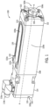
- FIG. 1 depicts a linear actuator system 100, exemplary of the linear actuator systems discussed above and as described in greater detail below.
- the linear actuator system 100 is used to drive an output rod or thrust tube 104 in reciprocating motion along a longitudinal axis A.
- thrust tube 104 is positioned at least partially within the main body or central portion of the actuator housing 108.
- the thrust tube 104 extends along the longitudinal axis A from a first (proximal) end oriented toward the proximal end region 105a of the linear actuator system 100, inside the housing 108, to a second (distal) end 104b toward the distal end region 105b of the linear actuator system 100, outside the housing 108.
- the distal or output end 104b of the thrust tube 104 is positioned at the axial extreme of distal region 105b.
- the distal end 104b of the thrust tube 104 can be coupled to a machine tool, workpiece, end effector, or other component.
- a motor assembly is positioned within the actuator housing 108, and configured to drive the thrust tube 104 in reciprocating motion along the longitudinal axis A.
- the thrust tube 104 moves generally between a first (retracted) position to a second (extended) position, in which the distal end 104b of the thrust tube 104 advances at least partially outside of actuator housing 108 and past the head assembly 112. This reciprocating motion between the first retracted position and the second extended position can be used to drive a machine tool in a corresponding fashion along the longitudinal axis A.
- proximal and distal are defined with respect to the internal components of the linear actuator system 100, and any workpiece or tool coupling located on the output end 104b of the thrust tube 104, outside of the actuator housing 108.
- distal refers to the direction of the output end 104b of the thrust tube 104 that is at least partially outside of the housing 108 (and any workpiece or tooling component connected thereto)
- proximal refers to the direction away from the output end 104b of the thrust tube 104 (and any connected workpiece or tool).
- the terms may be interchanged without loss of generality, depending on design or drawing convention.
- the actuator housing 108 shown in FIG. 1 generally encloses a portion of the thrust tube 104.
- the actuator housing 108 further encloses a motor assembly and any other appropriate components that are used to drive the reciprocating motion of the thrust tube 104.
- Exemplary internal components are described in greater detail with respect to FIG. 2 , including a motor assembly (e.g., magnets, windings, and rotors), bushings, bearings, and a nut assembly coupled to a lead screw or screw shaft for converting rotational motion of the rotor into reciprocating motion of the thrust tube 104 along central axis A.
- the main or central portion of the actuator housing 108 can be formed by extruding or machining a generally hollow shape configured to enclose the motor assembly and other internal components, or as a multi-piece assembly. More generally, the actuator housing can encompass the main or central housing section 108 together with a head assembly 112, bearing block 114 and rear cover 116, attached together along the central axis A. As shown in FIG 1 , for example, the head assembly 112 is coupled to the distal end of the main housing 108 along the longitudinal axis A, in the distal region 105b of the actuator system 100, and the main bearing block 114 and rear cover 116 are coupled to central portion of the housing 108 in the proximal region 105a.
- the linear actuator system 100 converts rotational motion (e.g., of an internal screw) into reciprocating motion of the thrust tube 104.
- the main bearing block 114 can enclose various components adapted for precision control of the reciprocating motion, such as a rotary encoder that detects a rotational position of the internal screw and other control components or logic that uses the detected position to determine a reciprocated position of the thrust tube 104.
- Bearing block connectors 117 can be used to removably attach the main bearing block 114 to the actuator housing 108.
- the main bearing block 114 can be interchangeable, allowing the linear actuator to be used with a variety of different encoders, sensors, feedback mechanisms, and so on, as appropriate for a given application.
- an adapter is provided to connect the screw shaft and other internal components of the actuator to be associated with different bearing blocks, including those having different sizes or configurations than the main bearing block 114 shown with respect to FIG. 1 .
- External connectors 115a, 115b are positioned at or on the main bearing block 114.
- the connectors 115a, 115b are used to connect the linear actuator system 100 to various external systems and processes.
- the connectors 115a, 115b can be used to electrically connect the linear actuator system 100 to a power source.
- the connectors 115a, 115b can be used to provide a data connection between the linear actuator system 100 and an external computing device, which may be adapted to control one or more operations of the linear actuator system 100.
- Connectors 115a, 115b are illustrative. Connectors 115a, 115b can be used to provide connections or links between the linear actuator system 100 and an external power supply, computing device, and other peripheral systems, or other connections can be used. As one example, a remote computing device may be wirelessly coupled with one or more internal components of the linear actuator system 100. As such, control signals and data outputs can be exchanged between the remote computing device and the linear actuator system 100 by wireless connection, according to various protocols.
- the main bearing block 114 is shown connected to a rear cover 116.
- the rear cover 116 can be a plate or other closure that operates to close and seal an interior of the main bearing block 114 from an external environment.
- the rear cover 116 can also provide access to service or replace various components that are held within the main bearing block 114.
- the main bearing block 114 may include various sensors and other electronics that may be shielded by the rear cover 116.
- rear cover connectors 119 such as bolts, screws or other mechanical connectors can be used to secure to rear cover 116 to the main bearing block 114.
- the rear cover connectors 119 can be manipulated in order to remove the rear cover 116 from the main bearing block 114 and allow for servicing of the components held therein.
- a front head assembly 112 is removably attached to the actuator housing 108 at the distal end region 105b, for example using screws, bolts or similar front head connectors 113.
- the front head assembly 112 houses an adjustable guide bushing that can provide stability to the thrust tube 104, as the thrust tube 104 travels in reciprocating motion along the longitudinal axis A.
- the front head assembly 112 in cooperation with the adjustable guide bushing 130 can also provide rotational stability to the thrust tube 104.
- the thrust tube 104 can define a flat 106 or other surface contour.
- the front head assembly 112 can include one or more features, include the adjustable guide bushing, with a correspondingly contoured feature that is key to the flat 106, thereby helping the thrust tube 104 maintain rotational stability as the thrust tube 104 travels along longitudinal axis A.
- the linear actuator system 100 described herein also includes various cooling features, systems and assemblies that help reduce a temperature of the motor assembly contained within the actuator housing 108.
- the linear actuator system 100 is shown as including a cooling loop 120.
- the cooling loop 120 can be at least partially embedded, potted or seated with a thermally conductive material 123, within a channel or recessed feature 110 defined in the actuator housing 108.
- the cooling loop 120 can be formed with the thermally conductive material 123 disposed at least partially about the cooling loop 120 to conduct heat from the actuator housing 108.
- the cooling loop 120 can include a hollow interior conduit or tube through which cooling fluid is routed.
- a first fluid coupling 122a and a second fluid coupling 122b can be used to couple the cooling loop 120 with a fluid source for circulating the cooling fluid.
- the fluid couplings 122a, 122b can include inlet and outlet couplings, valves or quick-disconnect features adapted for removable attachment of the cooling loop 120 to conduit, hose or other fluid flow component configured to cycle fluid through the cooling loop 120.
- the recessed feature 110 is shown formed in a first side 109a of the actuator housing 108.
- the cooling loop 120 is therefore at least partially embedded, potted or seated at the first side 109a of the actuator housing 108.
- the cooling loop 120 in the example of FIG. 1 conducts heat substantially from the first side 109a.
- the second side 109b or other side of the actuator housing 108 may be adapted to receive another cooling component, such as a modular cooling jacket or other cooling jacket that attaches to a side of the actuator housing 108 that is otherwise not associated with the cooling loop 120 shown in FIG. 1 .
- the linear actuator system 100 can be tuned to provide the level of cooling as needed for a particular application.
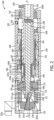
- FIG. 2 is a cross-sectional view of the actuator system 100.
- linear actuator system 100 includes a motor assembly 140 disposed within the central portion of the actuator housing 108.
- a head assembly 112 is coupled to the central housing 108 in the distal end region 105b, e.g., using one or more front head connectors 113, or similar mechanical attachments.
- a bearing block 114 and rear cover 116 are connected to the central housing 108 at the proximal end 105a, opposite the head assembly 12, for example using one or more bearing block connectors 117 and rear cover connectors 119.
- Motor assembly 140 is located inside the central housing 108.
- Motor assembly 140 typically includes a stator with a number of motor windings 142, magnets 144 (e.g., permanent magnets or electromagnets), and a rotor 146.
- motor assembly 140 may be configured as a hollow shaft motor having one or more stationary (stator) motor windings 142, with a centrally located, hollow rotor 146 positioned radially inwardly of stator windings 142, inside actuator housing 108.
- windings 142 are positioned radially outwardly of rotor 146, for example, being fixed to (or fixed relative to) actuator housing 108.
- rotor 146 may have generally cylindrical outer and inner surfaces, with stator windings 142 and rotor 146 surrounding a centrally located linear thrust mechanism that includes a threaded lead screw or screw shaft 150, with nut (or nut assembly) 160 directly coupled to the thrust tube, output rod, or other load transfer structure.
- the thrust mechanism is configured to convert rotational motion of rotor 146 to linear movement of thrust tube 104.
- the thrust mechanism includes the externally threaded, elongated lead screw or screw shaft 150 in combination with an internally threaded nut assembly 160, positioned radially inward of and substantially surrounded by rotor 146.
- screw shaft 150 may include an externally threaded section, provided with threads along a substantial portion of the shaft length.
- thread and “threaded” may thus be used to define the main threaded section of screw shaft 150, including, but not limited to, conventional threads, Acme- or ACME-type threads, roller screw threads, ball nut threads, and other threaded features suitable to convert rotational motion of rotor 146 to linear motion of thrust tube 104.
- the lead screw or screw shaft 150 may also include a proximal extension 152.
- Proximal extension 152 may be formed as an unthreaded, reduced diameter section at the proximal end of screw shaft 150.
- the proximal extension 152 extends through hub 148 and may be rotationally coupled thereto, for example, by providing the inner surface of hub 148 with a complementary taper, or with a lock and key arrangement.
- Thrust bearing 170 can be positioned radially outward of hub 148 and configured to support hub 148 and the proximal extension 152 of screw shaft 150 within actuator housing 108.
- the thrust bearing 170 can include a pair of bearings that are adapted to provide a higher force capacity. Accordingly, while FIG. 2 shows the thrust bearing 170 as a single bearing, two or more bearings can be provided at or adjacent the proximal end to support screw shaft 150 within the housing 108.
- rotor 146 and hub 148 may be provided as a single, integrated component, or as separate parts.
- proximal end of rotor 146 can also be rigidly connected with the axially extending (rotor mounting portion) of hub 148, so that rotation of rotor 146 causes a corresponding rotation of hub 148 and lead screw (or screw shaft) 150.
- a feedback device or block 176 can also be arranged adjacent the proximal extension 152 of the screw shaft 150, with a mounting plate 179 facilitating attachment within the main bearing block 114.
- a rotary encoder 178 or other position sensor/controller may be mounted to the proximal extension 152 of screw shaft 150, utilizing an adapter 172.
- a hollow shaft (incremental or absolute) encoder 178 can be coupled to the adapter 172 using a threaded connection or other mechanical means, with the rotation sensor element mounted directly onto the adapter 172.
- the adapter 172 can also be coupled to the screw shaft 150 in a manner that causes the adapter 172 to rotate with the rotation of the screw shaft 150.
- adapter 172 is shown in FIG. 2 for use with a hollow bore feedback device, other configurations are possible and contemplated herein.
- feedback devices that do not require a hollow bore connection can be implemented, including those in which a direct coupling of device and adapter 172 and/or screw shaft 150 is utilized (e.g., such an Oldham coupler, threaded coupling, or other mechanical engagement).
- the screw shaft 150 includes a coupling feature or fitting 154 at a proximal end of the screw shaft 150. While many configurations are possible, the coupling feature 154 defines a proximal fitting 155 or socket that is adapted to receive the adapter 172.
- the adapter 172 can define an adapter fitting 173 that is a reduced diameter portion of the adapter 172.
- the adapter fitting 173 can be inserted into the proximal fitting 155 of the screw shaft 150.
- the adapter fitting 173 and the proximal fitting 155 can define a press fit or interference fitting, or a threaded coupling.
- a lock nut 175 can also be provide to restrain the rotational and axial movement of the adapter 172 and the screw shaft 150 relative to one another.
- a load distribution washer 171 is shown in FIG. 2 with the proximal extension 152 and the coupling feature 154 extending therethrough.
- the load distribution washer 171 can further enhance the stability of the screw shaft 150 during operation.
- the load distribution washer 171 can be pressed between the lock nut 175 and the thrust bearing 170 / hub 148 along the longitudinal axis A, thereby providing a more evenly distributed load along the longitudinal axis A-A for the components configured for rotational motion thereabout.
- the distal end of thrust tube 104 may be adapted for association with an adjustable guide bushing 130 that supports and stabilizes the distal end of the thrust tube 104 relative to actuator housing 108.
- the adjustable guide bushing 130 may be generally arranged at the distal end 105b of the system 100.
- the adjustable guide bushing 130 may be configured to provide axial and rotational stability to the thrust tube 104 as the thrust tube 104 reciprocates along the longitudinal axis A between a retracted and an extended state, as explained in detail with respect to FIG. 4 . This can involve keying one or more contours of the adjustable guide bushing 130 to a corresponding contour of the thrust tube 104 (e.g., the flat 106 of FIG. 1 ).
- the distal end of rotor 146 may be provided with a ledge, recessed portion, or other feature to accommodate a secondary bearing 158 configured to support and stabilize the distal end of the rotor 146 relative to actuator housing 108.
- a secondary bearing 158 may be provided, which may be adapted to float or travel in an axial direction (parallel to rotational axis A of rotor 146 and lead screw 150), in order to accommodate thermal expansion of rotor 146 and other components.
- the central portion of rotor 146 can be provided with a number of magnets 144, mounted either along the outer surface of rotor 146, or inlaid within the outer surface of rotor 146, adjacent the stator windings or coils 142.
- rotor 146 can be machined to form axially-extending channels or grooves along the central portion of rotor 146, and magnets 144 can be inlaid within the grooves, between the corresponding (and radially thicker) axial rib sections. This also may provide rotor 146 with thicker wall sections at the proximal and distal ends, extending axially on either side of magnets 144.
- Rotor 146 also provides for simple assembly of the motor 140, without additional tooling for alignment, while providing sufficient material to reduce or limit core saturation due to the high flux density of magnets 144, and reducing stray flux and flux leakage.
- rotor 146 When motor assembly 140 is operated, rotor 146 rotates in a first (e.g., clockwise) or second (e.g., counter-clockwise) direction about longitudinal axis A.
- the proximal end of rotor 146 is connected to screw shaft 150 (e.g., via hub 148), so that rotation of rotor 146 results in a corresponding rotation of screw shaft 150, in either the first or second direction.
- the nut assembly 160 may include internal threads, for example a recirculating ball screw or roller nut 162 which mates with external threads on the outer surface of screw shaft 150 to convert rotational motion of rotor 146 to linear (axial) motion of nut assembly 160.
- the nut assembly 160 and thrust tube 104 are directly coupled together, and thus move in unison along the longitudinal axis A when screw shaft 150 is rotated by rotor 146 of motor assembly 140.
- the nut assembly 160 and the thrust tube 104 can be directly coupled to one another, absent additional intervening housing or bearing structures, providing linear actuator system 100 with a more compact design. Further, without additional housing or bearing structures, the screw shaft 150 can be oversized or generally larger than conventional designs relative to the dimensions of the actuator housing 108. In this manner, the actuator system 100 can provide enhanced torque relative to the size of the system 100, while using the cooling systems described herein to remove heat and maintain a temperature of the system 100.
- the nut assembly 160 includes a first end 161a adjacent the hub 148 and a second end 161b adjacent the thrust tube 104.
- the second end 161b directly abuts the thrust tube 104, for example at a mechanical coupling or fitting 167.
- a complementary fitting 168 is defined on the second end 161b of the nut assembly 160, for example a threaded coupling, press fit or interference fitting adapted for engagement with the fitting 167 on the proximal end 104a of the thrust tube 104.
- the thrust tube 104 can be directly coupled with the roller nut 162 or nut assembly 160, absent additional housing or load bearing structures between the mechanical coupling 168 on the second end 161b of the nut assembly 160 and the complementary fitting 167 on the proximal and of the thrust tube 104.
- the roller nut 162 is held within the nut assembly 160 by a carrier 166 that extends between the first and second ends 161a, 161b.
- the carrier 166 defines the mechanical coupling 168 at the second end 161b of the nut assembly 160.
- End caps 164a, 164b can be provided at the respective first and second ends 161a, 161b, for structural support and to mitigate debris entry into roller nut 162.
- the end caps 164a, 164b can define the mechanical coupling 168, alone or in conjunction with the carrier 166.
- nut assembly 160 and thrust tube 104 may move in a distal direction in response to a first (clockwise) rotation of rotor 146 and the lead screw or screw shaft 150, the output end of the thrust tube 104 away from the actuator housing 108 along axis A of the linear actuator system 100.
- motor assembly 140 drives rotor 146 and screw shaft 150 in the opposite (counter-clockwise) direction
- nut assembly 160 and thrust tube 104 move in a proximal direction along the longitudinal axis A, retracting the thrust tube 104 into the actuator housing 108.
- the thrust tube 104 can be retracted into an inner volume 127 of the actuator housing 108.
- a bumper 128 may be provided between the thrust tube 104 and the screw shaft 150 or other component of the system 100.
- the bumper 128 defines a deformable interface region between inner surface of the thrust tube 104 at working or output (distal) end, and the adjacent end of the screw shaft 150, cushioning impact and reducing contact forces at the inward-most position of thrust tube 104.
- motor assembly 140 is controllable to provide any desired linear or axial motion of thrust tube 104, and any workpiece or tooling connected thereto, based on the rotational motion of rotor 146 and screw shaft 150.
- FIG. 3 is a cross-sectional view of the nut assembly 160 and thrust tube 104, directly coupled to one another.
- the nut assembly 160 is shown directly engaged with a proximal end of the thrust tube 104.
- the nut assembly 160 can extend continuously from the first end 161a to the second end 161b, with the second end 161b abutting the thrust tube 104.
- the nut assembly 160 and the thrust tube 104 can thus be directly coupled to one another, absent additional housing or bearing structure intervening between the nut assembly and the proximal end of the thrust tube.
- the mechanical coupling 168 can include a threaded coupling, press fit or interference fitting on the second end 161b of the nut assembly 160.
- the mechanical coupling 168 can be adapted to engage a complementary fitting or coupling 167 on the proximal end 104a of the thrust tube 104, opposite the distal and 104b, within a common outer diameter of the thrust tube 104 and nut assembly 160.
- the nut assembly 160 may define a nut assembly outer surface 169 and the thrust tube 104 can define a thrust tube outer surface 126.
- the nut assembly outer surface 169 and the thrust tube outer surface 126 can be substantially continuous with one another, each having a common or similar outer diameter.
- the directly coupled nut assembly 160 and the thrust tube 104 can be arranged within the rotor 146, with the rotor 146 adapted to accommodate and match the common outer diameter, with a desired tolerance, rather than being sized larger for additional intervening housing or bearing structures.
- the nut assembly 160 and the directly coupled thrust tube 104 can be configured to house an oversized or larger lead screw or screw shaft 150, facilitating the compact designs described herein with the enhanced torque due to the larger screw shaft 150 fitting in a more compact space.
- the output (distal) end 104b of the thrust tube 104 is shown with a mechanical coupling or similar attachment fixture on the rod end 124.
- the rod end or attachment fixture 124 can be configured as threaded coupling or similar fixture for a machine tool component, located on the output (distal) end 104b of the thrust tube 104, outside the actuator housing 108.
- an effector for a weld gun or other machine tool component can be coupled to the rod end 124, and driven in axial motion by the thrust rod 104.
- the rod end (or fixture) 124 is typically positioned by thrust tube 104 at or adjacent the distal end 105b of the linear actuator system 100.
- the rod end 124 defines a common interface that allows the thrust tube 104 (and more generally, the linear actuator system 100) to engage a variety of different effectors and other machine tool components.
- the rod end 124 can also include a variety of engagement features, including pins, clamps, screws, grooves, locking mechanisms, and so forth, which are used to secure the effector or machine tool component to the thrust tube 104.
- a weld electrode or similar machine tool component can be directly coupled or secured to the rod end 124, and move with the reciprocating motion of the thrust tube 104.
- an end effector or other load bearing component can be coupled to the rod end 124 in order to manipulate the machine tool, for example a welding gun arm.
- a grease zerk or similar fitting 129 Adjacent the tool attachment, a grease zerk or similar fitting 129 is provided on the distal end of the thrust tube 104, positioned at the distal end 105b of the actuator system 100.
- the grease zerk 129 can be used to receive a supply of lubricant for the inner volume 127.
- a seal 125 such as an O-ring can be mounted at the distal (output end) of the thrust tube 104, mitigating lubricant leakage.
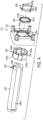
- FIG. 4 is an exploded view of the thrust tube 104 and the front head assembly 112.
- the front head assembly 112 generally closes the distal end 105b of the actuator housing 108 and helps provide stability to the thrust tube 104.
- the front head assembly 112 include various components that cooperate to receive the thrust tube 104 and guide the reciprocal movement of the thrust tube 104, including the adjustable guide bushing 130, the thrust tube wiper 136 and the thrust tube scraper 138, as shown in FIG. 4 .
- the thrust tube 104 can include one or more surface contours that are keyed to corresponding features of the front head assembly 112 for reciprocal movement there along.
- the thrust tube 104 is shown with a first flat 106a and a second flat 106b.
- the first and second flats 106a, 106b can be positioned on opposing sides of the thrust tube 104 and define a substantially flat or planar contour along the longitudinal dimension of the thrust tube 104.
- the thrust tube 104 can include more or fewer flats, including flats in different positions and configurations.
- the flats 106a, 106b can be keyed or matched to corresponding contours of the front head assembly 112.
- the front head assembly 112 can receive the thrust tube 104
- the flats 106a, 106b can mitigate rotational movement of the thrust tube 104 as the thrust tube reciprocates along the longitudinal axis.
- the adjustable guide bushing 130 can provide a first bushing portion 132a and a second bushing portion 132b that receive the thrust tube 104 within the front head assembly 112.
- the first bushing portion 132a can define a first keyed contour 134a and the second bushing portion 132b can define a second keyed contour 134b.
- the adjustable guide bushing 130 can be adapted to receive the thrust tube 104 with the flat 106a engaged with the first keyed contour 134a and the flat 106b engaged with the second keyed contour 134b. As the thrust tube 104 reciprocates through the adjustable guide bushing 130, the keyed contours 134a, 134b thus impair rotational movement of the thrust tube 104, due to the engagement with the respective ones of the flats 106a, 106b. Pins 135 are provided to install the adjustable guide bushing 130 in the system 100.
- the flats 106a, 106b can be further keyed to contours of the front head assembly 112, such as the first front head contour 131a and the second front head contour 131b.
- the thrust tube wiper 136 can include a first wiper engagement contour 137a, second wiper engagement contour 137b for engagement with the first and second flats 106a and 106b.
- the thrust tube scraper 138 is also shown the first scraper engagement contour 139a and the second scraper engagement contour 139b for engagement with the first and second flats 106a, 106b.
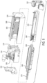
- FIG. 5 is an exploded view of linear actuator system 100, including a motor assembly 140, lead screw or screw shaft 150 and nut assembly 160 directly coupled to the thrust tube 104.
- the directly coupled nut assembly 160 and thrust tube 104 are adapted to receive the screw shaft 150, with the nut assembly 160 engaged with the external outer threads of the screw shaft 150.
- the rotor 146 extends along and over the directly coupled nut assembly 160 and thrust tube 104 so that the nut assembly 160 and the thrust tube 104 fit in an annular space between the screw shaft 150 and the rotor 146.
- the rotor 146 is positioned within the actuator housing 108, adjacent the cooling loop 120.
- the cooling loop 120 is therefore arranged to remove heat from the motor assembly 140 through the actuator housing 108.
- the adapter 172 is shown in FIG. 5 as connected to the screw shaft 150.
- the adapter 172 generally operates to couple the screw shaft 150 to the encoder 178 of the main bearing block 114.
- the adapter 172 can have an appropriate length in order to extend from the screw shaft 150 to the encoder 178. In this manner, the screw shaft 150 and actuator system 100 can be manufactured separately from the encoder 178 and main bearing block 114, with the adapter 172 tuned to effectively extend a length of the screw 150 to meet the specific characteristics of the encoder 178.
- the actuator system 100 can include a common sized screw shaft 150 and the adapter 172 can be any one of a variety of different sizes to connect the commonly sized screw shaft 150 to the specific encoder of a given application.
- FIG. 6 is a cross-sectional view of the lead screw or screw shaft 150 and adapter 172.
- the screw shaft 150 can have a shaft length l s and the adapter 172 can have an adapter length l a .
- the shaft length l s can be a length value that is standardized across a series or particular model of actuator system 100.
- the adapter 172 can have an adapter length l a that is tailored to the requirements of the encoder 178.
- FIG. 7 is an exploded view of the main bearing block 114 assembly for a linear actuator system 100.
- the main bearing block 114 can be associated with or otherwise include the connectors 115a, 115b, the rear cover 116, the thrust bearing 170, the distribution washer 171, the lock nut 175, the feedback device or feedback block 176, the rotary encoder 178 and the mounting plate 179.
- an alternate feedback block 176' can be substituted for the feedback block 176.
- Suitable feedback blocks 176' can include an integrated pilot feature with braking assembly. In this configuration, the braking assembly is configured to brake rotation of the screw shaft responsive to feedback from the resolver or encoder.
- Other variations of the feedback block 176 or 176' may be provided, and are encompassed in the disclosure here.
- FIG. 8 is a top view of the linear actuator system 100.
- the cooling loop 120 is shown coupled with the actuator housing 108.
- the actuator housing 108 can define the recessed feature 110 with the first side of the actuator housing 108.
- the recessed feature 110 can be sized and shaped in a manner so that the cooling loop 120 can be at least partially embedded, potted or seated within the actuator housing 108, along the selected side.
- the cooling loop 120 extends along the recessed feature 110 from the first fluid coupling 122a near the proximal end 105 a of the actuator housing 108 toward the distal end 105b of the actuator housing 108 and back to second fluid coupling 122b near the proximal end 105a.
- the cooling loop 120 can resemble a U-shaped conduit.
- the cooling loop 120 can be defined by other geometries, including geometries in which the cooling loop 120 extends the actuator housing 108 multiple times, such as extending in a serpentine pattern between the near the proximal and distal ends 105a, 105b, similar to a radiator or other cooling structure.
- FIG. 9 is a front view of the actuator system 100, showing an anti-rotation feature for the thrust tube 104.
- the thrust tube 104 can include flats 106a, 106b on opposing sides.
- the front head assembly 112 can include one or more components that are keyed to the flats 106a, 106b.
- the front head assembly 112 can housing a guide bushing and other features that have contours matching those of the flats 106a, 106b. In this manner, as the thrust tube 104 reciprocates, the thrust tube 104 may be prevented from rotational movement.
- FIG. 10 is a back view of the actuator system 100.
- the connectors 115a, 115b are shown.
- the connectors 115a, 115b can be adapted for power and control communications.
- one or both of the first connector 115a and the second connector 115b can be used to connect the linear actuator system 100 to a power supply, remote computing unit, and other external system or process.
- Each of the first connector 115a and the second connector 115b can be configured to connect the linear actuator system 100 to distinct systems.
- the first connector 115a may be configured to connect the linear actuator system 100 to a power supply and the second connector 115b may be configured to connect the linear actuator system 100 to a remote computing unit.
- more or fewer connectors may be provided, as may be appropriate for a given application.
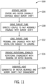
- FIG. 11 is a flow diagram illustrating a process or method 1100 for operating a linear actuator system.
- process 1100 may be used with a linear actuator system 100, in any of the examples and embodiments described herein. While the specific operations of method 1100 are presented in a particular arrangement, method 1100 may include more, fewer or different steps than those that are illustrated, consistent with the teachings of this disclosure. The operations of method 1100 can also be performed in any order or combination, with or without any of the additional processes and techniques described herein.
- the motor of the linear actuator is operated.
- the motor has a stator and a rotor disposed about a screw shaft of a linear actuator.
- the rotor rotates about a longitudinal axis.
- the motor assembly 140 of the linear actuator system 100 is operated.
- the stator windings or coils 142 and the rotor 146 are disposed about the lead screw or screw shaft 150.
- the rotor 146 rotates about the longitudinal axis A-A.
- a thrust tube is driven along the longitudinal axis.
- the thrust tube is directly coupled to a nut assembly in threaded engagement with the screw shaft.
- the thrust tube 104 is driven in reciprocating movement along the longitudinal axis A-A.
- the thrust tube 104 is directly coupled to the nut assembly 160.
- directly coupling the thrust tube 104 and the nut assembly 160 can include a direct physical engagement between the nut assembly 160 and the proximal end of the thrust tube 104, absent additional housing or bearing structures intervening there between.
- the nut assembly 160 is in threaded engagement with the screw shaft 150.
- the thrust tube is loaded.
- the thrust tube extends from a proximal end in direct physical engagement with the nut assembly to a distal end subject to the loading.
- the thrust tube 104 can be loaded at the rod end or attachment fixture 124.
- the rod end 124 can be coupled with a weld electrode or weld gun effector for use in resistance welding operations.
- weld electrodes There may be substantial mechanical loading on the weld electrodes in order to provide the mechanical coupling required to ensure high quality welds.
- the inductive reaction forces can cause the welding gun and actuator assembly to deflect off axis, causing the electrodes to slip or skid out of the desired position and potentially impacting weld quality.
- the adjustable guide bushing 130 supports the thrust tube 104.
- the adjustable guide bushing 130 includes the keyed contours 134a, 134b that are adapted for engagement with corresponding ones of the flats 106a, 106b of the thrust tube 104.
- the adjustable guide bushing 130 can therefore mitigate rotational movement of the thrust tube 104, with the first and second bushing portions 132a, 132b preventing rotational movement of the thrust tube 104.
- heat is dissipated with a cooling loop.
- the cooling loop 120 can be partially embedded, potted or seated within the actuator housing 108.
- the actuator housing 108 can define a recessed feature 110 with the cooling loop 120 positioned at least partially therein.
- the cooling loop 120 extends along the actuator housing 108 and along the stator and rotor disposed about the screw shaft.
- a thermally conductive material 123 can be at least partially disposed about the cooling loop 120 conducting the heat from the housing to the cooling loop 120.
- a linear actuator generally includes a thrust tube configured for reciprocating motion along a longitudinal axis.
- a distal end of the thrust tube is configured to engage a machine tool, such as a welding, crimping, clamping, or other tool, thereby allowing the linear actuator to drive the machine tool in reciprocating motion with the thrust tube.
- the linear actuator can be used in an automated assembly or manufacturing and other settings where the distal end of the thrust tube is subject to loading, including both axial (e.g., mechanical) loading and transverse or radial (e.g., mechanical or current-based inductive) loading, which generates forces tending to displace the thrust tube at the distal end.
- a nut assembly directly couples a rotor and screw shaft to the thrust tube to provide a compact, efficient design.
- the actuator configurations described herein have the ability to accept a modular water cooling assembly, or other active or passive modular cooling unit.
- the addition of the cooling assembly adds to the motor capacity, allowing the actuator to operation with a higher-capacity, while maintaining acceptable system temperatures.
Landscapes
- Engineering & Computer Science (AREA)
- General Engineering & Computer Science (AREA)
- Mechanical Engineering (AREA)
- Transmission Devices (AREA)
- Connection Of Motors, Electrical Generators, Mechanical Devices, And The Like (AREA)
Description
- This application is directed to linear actuator technology, including, but not limited to, linear actuator systems for robotic welding, automated machine tool systems, and other programmable tool applications. More generally, the disclosure relates to integrated motor linear actuator systems with advanced designs adapted for improved power-to-weight ratio, size envelope, stroke length and thermal performance.
- This disclosure relates to linear actuators for use in automated machine tool systems, including robotic welding and other programmable tool applications. More generally, the disclosure relates to the thrust-bearing elements of a linear actuator system, including thrust tube and thrust rod components.
- Industrial robots utilize a wide variety of different actuator technologies, in order to automate manufacturing processes including robotic welding, injection molding, fixture clamping, packaging, assembly, surface coating, and product inspection and testing. Other high-volume and precision production manufacturing applications are also included, particularly where machine tool speed, accuracy, endurance, service life and operational costs are important engineering factors.
- In robotic welding and automated or programmable machine tool applications, actuators can be arranged to position a welding gun or similar apparatus with respect to a workpiece, using a linear actuator to position the electrode or end effector. Suitable applications include, but are not limited to, short-stroke clamping operations for arc, spot or resistance welding, projection welding, and friction stir welding. Linear actuators are also used in a range of other programmable tool applications, including robotic, pedestal, and fixture-type manufacturing operations.
- Actuator speed, precision and service life remain important design factors across these different applications, along with system size and weight considerations. As a result, there is a continuing need for improved linear actuator designs, which can provide increased positioning accuracy with reduced deflection and tool displacement, within a desired tooling weight and size envelope, and a reasonable cost.
-
WO2015/081951A1 relates to an actuator with a planetary roller screw (PWG) and describes a planetary roller nut carrier engaged within a first sleeve A, which sits nonrotating and axially fixed in a second sleeve B. The sleeve B extends radially outward of the roller nut carrier, and then axially along sleeve A, in which the roller nut carrier is disposed, to approximately the middle portion of the nut carrier and sleeve assembly. - According to the invention, the problem is solved by the subject matter outlined in independent apparatus claims 1 and 14 and independent method claim 9. Advantageous further developments of the invention are set forth in the dependent claims.
- In addition to the representative examples and embodiments described here, other embodiments are also encompassed, as disclosed by reference to the drawings, and by study of the following description.
-
-
FIG. 1 is a front isometric view of a linear actuator system. -
FIG. 2 is a cross-sectional view of the linear actuator system. -
FIG. 3 is a cross-sectional view of a nut assembly and thrust tube for a linear actuator system. -
FIG. 4 is an exploded view of the thrust tube and a front-end bearing assembly for a linear actuator system. -
FIG. 5 is an exploded view of a linear actuator system, including a motor assembly and screw shaft. -
FIG. 6 is a cross-sectional view of the screw shaft, showing roller screw and adapter portions. -
FIG. 7 is an exploded view of a back-end bearing block assembly for a linear actuator system. -
FIG. 8 is a top view of a linear actuator system, showing a cooling assembly for the actuator housing. -
FIG. 9 is a front view of the linear actuator system, showing an anti-rotation feature for the thrust tube. -
FIG. 10 is a back view of the liner actuator system, showing connectors for power and control communications. -
FIG. 11 is a flow diagram illustrating a method for operating a linear actuator system. - Linear actuator systems can be provided in a variety of different sizes and configurations, depending on application, service, and operational requirements. Integrated-motor actuator systems provide a compact, efficient design, with the central housing section also serving as the stator housing. For example, a set of stator coils can be mounted to the inside the central housing section, with a rotor and screw shaft extending inside the stator, along the central axis. A nut assembly couples the rotor and screw shaft to a thrust tube or output rod, which moves longitudinally along the axis in response to rotation of the rotor.
- Integrated motor actuators can be produced at relatively low cost with improved electromechanical efficiency and manufacturing advantages. Additional design benefits include high speed and positioning accuracy, with a reduced size envelope and improved power-to-weight ratio.
- Weight can be an important design consideration in applications where the actuator device is typically carried by a robot, along with associated welding gun equipment or other machine tooling components. Less system weight also reduces loading on the robot arm, increasing speed and allowing for smaller robot systems with more precise positioning capability and higher rates.
- The body portion of the actuator housing can be held together between end caps, for example using tie rods or similar mechanical fasteners. This design can also reduce weight, as compared to thicker-walled configurations, and improve the system's ability to cool the motor drive, which is also a consideration in applications requiring the device to perform at high repetition rates (e.g., more welds per minute), or with greater travel in each movement. Higher rates and greater travel distances both mean additional mechanical work output; that is, the motor drive needs to work harder, and the system thus generates more heat.
- To address these concerns, the actuator configurations described here are adapted to accommodate a cooling assembly, for example an active water-cooled system or passive cooling structure. The addition of a cooling assembly can improve the motor capacity, for example up to two times or more, while maintaining acceptable system temperatures. In some embodiments the cooling assembly can be formed within the actuator housing, or otherwise permanently installed at the point of manufacture. In other embodiments, a modular cooling assembly can be adapted for selectively coupling (and decoupling) along one or more different sides or longitudinal section of the actuator housing.
- Typical electric motor drives include an internal rotor, mounted with rotational bearings each end. The bearings are adapted to support the length of the rotor component in rotation about the longitudinal axis of the actuator, with precise clearance between the rotor and stator along the rotor length. In some configurations, the rotor can be supported by a single rotational bearing assembly at one end; e.g., at the proximal end, or between the proximal and distal ends. The rotor can also be provided in a short, standard or elongated configuration, with additional design features to reduce the mass and moment of inertia of the both the rotor and other components of the actuator drive.
- Reference will now be made to the accompanying drawings, which assist in illustrating various features of the present disclosure. The following description is presented for purposes of illustration and description. Furthermore, the description is not intended to limit the inventive aspects to the forms disclosed herein. Consequently, variations and modifications commensurate with the following teachings, skill, and knowledge of the relevant art are within the scope of the present inventive aspects.
-
FIG. 1 depicts alinear actuator system 100, exemplary of the linear actuator systems discussed above and as described in greater detail below. Thelinear actuator system 100 is used to drive an output rod orthrust tube 104 in reciprocating motion along a longitudinal axis A. - In the configuration of
FIG. 1 ,thrust tube 104 is positioned at least partially within the main body or central portion of theactuator housing 108. Thethrust tube 104 extends along the longitudinal axis A from a first (proximal) end oriented toward theproximal end region 105a of thelinear actuator system 100, inside thehousing 108, to a second (distal)end 104b toward thedistal end region 105b of thelinear actuator system 100, outside thehousing 108. In this particular example, the distal oroutput end 104b of thethrust tube 104 is positioned at the axial extreme ofdistal region 105b. - The
distal end 104b of thethrust tube 104 can be coupled to a machine tool, workpiece, end effector, or other component. A motor assembly is positioned within theactuator housing 108, and configured to drive thethrust tube 104 in reciprocating motion along the longitudinal axis A. Thethrust tube 104 moves generally between a first (retracted) position to a second (extended) position, in which thedistal end 104b of thethrust tube 104 advances at least partially outside ofactuator housing 108 and past thehead assembly 112. This reciprocating motion between the first retracted position and the second extended position can be used to drive a machine tool in a corresponding fashion along the longitudinal axis A. - As used herein, the terms "proximal" and "distal" are defined with respect to the internal components of the
linear actuator system 100, and any workpiece or tool coupling located on theoutput end 104b of thethrust tube 104, outside of theactuator housing 108. In particular, the term distal refers to the direction of theoutput end 104b of thethrust tube 104 that is at least partially outside of the housing 108 (and any workpiece or tooling component connected thereto), and the term proximal refers to the direction away from theoutput end 104b of the thrust tube 104 (and any connected workpiece or tool). Alternatively, the terms may be interchanged without loss of generality, depending on design or drawing convention. - The
actuator housing 108 shown inFIG. 1 generally encloses a portion of thethrust tube 104. Theactuator housing 108 further encloses a motor assembly and any other appropriate components that are used to drive the reciprocating motion of thethrust tube 104. Exemplary internal components are described in greater detail with respect toFIG. 2 , including a motor assembly (e.g., magnets, windings, and rotors), bushings, bearings, and a nut assembly coupled to a lead screw or screw shaft for converting rotational motion of the rotor into reciprocating motion of thethrust tube 104 along central axis A. - The main or central portion of the
actuator housing 108 can be formed by extruding or machining a generally hollow shape configured to enclose the motor assembly and other internal components, or as a multi-piece assembly. More generally, the actuator housing can encompass the main orcentral housing section 108 together with ahead assembly 112, bearingblock 114 andrear cover 116, attached together along the central axis A. As shown inFIG 1 , for example, thehead assembly 112 is coupled to the distal end of themain housing 108 along the longitudinal axis A, in thedistal region 105b of theactuator system 100, and themain bearing block 114 andrear cover 116 are coupled to central portion of thehousing 108 in theproximal region 105a. - As described herein, the
linear actuator system 100 converts rotational motion (e.g., of an internal screw) into reciprocating motion of thethrust tube 104. The main bearing block 114 can enclose various components adapted for precision control of the reciprocating motion, such as a rotary encoder that detects a rotational position of the internal screw and other control components or logic that uses the detected position to determine a reciprocated position of thethrust tube 104.Bearing block connectors 117 can be used to removably attach the main bearing block 114 to theactuator housing 108. In this configuration, the main bearing block 114 can be interchangeable, allowing the linear actuator to be used with a variety of different encoders, sensors, feedback mechanisms, and so on, as appropriate for a given application. As described herein, an adapter is provided to connect the screw shaft and other internal components of the actuator to be associated with different bearing blocks, including those having different sizes or configurations than the main bearing block 114 shown with respect toFIG. 1 . -
External connectors main bearing block 114. Theconnectors linear actuator system 100 to various external systems and processes. For example, theconnectors linear actuator system 100 to a power source. Additionally or alternatively, theconnectors linear actuator system 100 and an external computing device, which may be adapted to control one or more operations of thelinear actuator system 100. -
Connectors Connectors linear actuator system 100 and an external power supply, computing device, and other peripheral systems, or other connections can be used. As one example, a remote computing device may be wirelessly coupled with one or more internal components of thelinear actuator system 100. As such, control signals and data outputs can be exchanged between the remote computing device and thelinear actuator system 100 by wireless connection, according to various protocols. - The
main bearing block 114 is shown connected to arear cover 116. Therear cover 116 can be a plate or other closure that operates to close and seal an interior of the main bearing block 114 from an external environment. Therear cover 116 can also provide access to service or replace various components that are held within themain bearing block 114. As one example, themain bearing block 114 may include various sensors and other electronics that may be shielded by therear cover 116. As shown inFIG. 1 ,rear cover connectors 119 such as bolts, screws or other mechanical connectors can be used to secure torear cover 116 to themain bearing block 114. Therear cover connectors 119 can be manipulated in order to remove therear cover 116 from themain bearing block 114 and allow for servicing of the components held therein. - A
front head assembly 112 is removably attached to theactuator housing 108 at thedistal end region 105b, for example using screws, bolts or similarfront head connectors 113. As described herein, thefront head assembly 112 houses an adjustable guide bushing that can provide stability to thethrust tube 104, as thethrust tube 104 travels in reciprocating motion along the longitudinal axis A. Thefront head assembly 112 in cooperation with theadjustable guide bushing 130 can also provide rotational stability to thethrust tube 104. As one example, thethrust tube 104 can define a flat 106 or other surface contour. Thefront head assembly 112 can include one or more features, include the adjustable guide bushing, with a correspondingly contoured feature that is key to the flat 106, thereby helping thethrust tube 104 maintain rotational stability as thethrust tube 104 travels along longitudinal axis A. - The
linear actuator system 100 described herein also includes various cooling features, systems and assemblies that help reduce a temperature of the motor assembly contained within theactuator housing 108. In the example ofFIG. 1 , thelinear actuator system 100 is shown as including acooling loop 120. Thecooling loop 120 can be at least partially embedded, potted or seated with a thermallyconductive material 123, within a channel or recessedfeature 110 defined in theactuator housing 108. Thecooling loop 120 can be formed with the thermallyconductive material 123 disposed at least partially about thecooling loop 120 to conduct heat from theactuator housing 108. Thecooling loop 120 can include a hollow interior conduit or tube through which cooling fluid is routed. Afirst fluid coupling 122a and a secondfluid coupling 122b can be used to couple thecooling loop 120 with a fluid source for circulating the cooling fluid. In some cases, thefluid couplings cooling loop 120 to conduit, hose or other fluid flow component configured to cycle fluid through thecooling loop 120. - The recessed
feature 110 is shown formed in afirst side 109a of theactuator housing 108. Thecooling loop 120 is therefore at least partially embedded, potted or seated at thefirst side 109a of theactuator housing 108. Thecooling loop 120 in the example ofFIG. 1 conducts heat substantially from thefirst side 109a. Asecond side 109b, or other side of theactuator housing 108, remains substantially uncoupled from thecooling loop 120. It will be appreciated, however, that in other cases, multiple cooling loops can be provided, with corresponding recessed features formed in to each respective side, or all sides, of theactuator housing 108 as needed. Yet further, in other cases, thesecond side 109b or other side of theactuator housing 108 may be adapted to receive another cooling component, such as a modular cooling jacket or other cooling jacket that attaches to a side of theactuator housing 108 that is otherwise not associated with thecooling loop 120 shown inFIG. 1 . In this configuration, thelinear actuator system 100 can be tuned to provide the level of cooling as needed for a particular application. -
FIG. 2 is a cross-sectional view of theactuator system 100. In this particular configuration,linear actuator system 100 includes amotor assembly 140 disposed within the central portion of theactuator housing 108. Ahead assembly 112 is coupled to thecentral housing 108 in thedistal end region 105b, e.g., using one or morefront head connectors 113, or similar mechanical attachments. Abearing block 114 andrear cover 116 are connected to thecentral housing 108 at theproximal end 105a, opposite the head assembly 12, for example using one or morebearing block connectors 117 andrear cover connectors 119.Motor assembly 140 is located inside thecentral housing 108. -
Motor assembly 140 typically includes a stator with a number ofmotor windings 142, magnets 144 (e.g., permanent magnets or electromagnets), and arotor 146. For example,motor assembly 140 may be configured as a hollow shaft motor having one or more stationary (stator)motor windings 142, with a centrally located,hollow rotor 146 positioned radially inwardly ofstator windings 142, insideactuator housing 108. Conversely,windings 142 are positioned radially outwardly ofrotor 146, for example, being fixed to (or fixed relative to)actuator housing 108. - When
motor assembly 140 is provided in hollow shaft or hollow rotor form, as shown inFIG. 2 ,rotor 146 may have generally cylindrical outer and inner surfaces, withstator windings 142 androtor 146 surrounding a centrally located linear thrust mechanism that includes a threaded lead screw or screwshaft 150, with nut (or nut assembly) 160 directly coupled to the thrust tube, output rod, or other load transfer structure. - The thrust mechanism is configured to convert rotational motion of
rotor 146 to linear movement ofthrust tube 104. As shown inFIG. 2 , for example, the thrust mechanism includes the externally threaded, elongated lead screw or screwshaft 150 in combination with an internally threadednut assembly 160, positioned radially inward of and substantially surrounded byrotor 146. In this configuration,screw shaft 150 may include an externally threaded section, provided with threads along a substantial portion of the shaft length. As used herein, the terms "thread" and "threaded" may thus be used to define the main threaded section ofscrew shaft 150, including, but not limited to, conventional threads, Acme- or ACME-type threads, roller screw threads, ball nut threads, and other threaded features suitable to convert rotational motion ofrotor 146 to linear motion ofthrust tube 104. - Depending on design, the lead screw or screw
shaft 150 may also include a proximal extension 152. Proximal extension 152 may be formed as an unthreaded, reduced diameter section at the proximal end ofscrew shaft 150. The proximal extension 152 extends through hub 148 and may be rotationally coupled thereto, for example, by providing the inner surface of hub 148 with a complementary taper, or with a lock and key arrangement. - Thrust bearing 170 can be positioned radially outward of hub 148 and configured to support hub 148 and the proximal extension 152 of
screw shaft 150 withinactuator housing 108. In some examples, thethrust bearing 170 can include a pair of bearings that are adapted to provide a higher force capacity. Accordingly, whileFIG. 2 shows thethrust bearing 170 as a single bearing, two or more bearings can be provided at or adjacent the proximal end to supportscrew shaft 150 within thehousing 108. Depending upon design,rotor 146 and hub 148 may be provided as a single, integrated component, or as separate parts. The proximal end ofrotor 146 can also be rigidly connected with the axially extending (rotor mounting portion) of hub 148, so that rotation ofrotor 146 causes a corresponding rotation of hub 148 and lead screw (or screw shaft) 150. - A feedback device or block 176, for example including an optional braking assembly, can also be arranged adjacent the proximal extension 152 of the
screw shaft 150, with a mountingplate 179 facilitating attachment within themain bearing block 114. Arotary encoder 178 or other position sensor/controller may be mounted to the proximal extension 152 ofscrew shaft 150, utilizing anadapter 172. For example, a hollow shaft (incremental or absolute)encoder 178 can be coupled to theadapter 172 using a threaded connection or other mechanical means, with the rotation sensor element mounted directly onto theadapter 172. In turn, theadapter 172 can also be coupled to thescrew shaft 150 in a manner that causes theadapter 172 to rotate with the rotation of thescrew shaft 150. Accordingly, while theadapter 172 is shown inFIG. 2 for use with a hollow bore feedback device, other configurations are possible and contemplated herein. For example, feedback devices that do not require a hollow bore connection can be implemented, including those in which a direct coupling of device andadapter 172 and/or screwshaft 150 is utilized (e.g., such an Oldham coupler, threaded coupling, or other mechanical engagement). - In the example of
FIG. 2 , thescrew shaft 150 includes a coupling feature or fitting 154 at a proximal end of thescrew shaft 150. While many configurations are possible, thecoupling feature 154 defines aproximal fitting 155 or socket that is adapted to receive theadapter 172. Theadapter 172 can define anadapter fitting 173 that is a reduced diameter portion of theadapter 172. Theadapter fitting 173 can be inserted into theproximal fitting 155 of thescrew shaft 150. In some cases, theadapter fitting 173 and theproximal fitting 155 can define a press fit or interference fitting, or a threaded coupling. Alock nut 175 can also be provide to restrain the rotational and axial movement of theadapter 172 and thescrew shaft 150 relative to one another. - A
load distribution washer 171 is shown inFIG. 2 with the proximal extension 152 and thecoupling feature 154 extending therethrough. Theload distribution washer 171 can further enhance the stability of thescrew shaft 150 during operation. Theload distribution washer 171 can be pressed between thelock nut 175 and thethrust bearing 170 / hub 148 along the longitudinal axis A, thereby providing a more evenly distributed load along the longitudinal axis A-A for the components configured for rotational motion thereabout. - The distal end of
thrust tube 104 may be adapted for association with anadjustable guide bushing 130 that supports and stabilizes the distal end of thethrust tube 104 relative toactuator housing 108. For example, theadjustable guide bushing 130 may be generally arranged at thedistal end 105b of thesystem 100. At thedistal end 105b, theadjustable guide bushing 130 may be configured to provide axial and rotational stability to thethrust tube 104 as thethrust tube 104 reciprocates along the longitudinal axis A between a retracted and an extended state, as explained in detail with respect toFIG. 4 . This can involve keying one or more contours of theadjustable guide bushing 130 to a corresponding contour of the thrust tube 104 (e.g., the flat 106 ofFIG. 1 ). - In some embodiments, the distal end of
rotor 146 may be provided with a ledge, recessed portion, or other feature to accommodate asecondary bearing 158 configured to support and stabilize the distal end of therotor 146 relative toactuator housing 108. As one possibility, asecondary bearing 158 may be provided, which may be adapted to float or travel in an axial direction (parallel to rotational axis A ofrotor 146 and lead screw 150), in order to accommodate thermal expansion ofrotor 146 and other components. - The central portion of
rotor 146 can be provided with a number ofmagnets 144, mounted either along the outer surface ofrotor 146, or inlaid within the outer surface ofrotor 146, adjacent the stator windings or coils 142. For example,rotor 146 can be machined to form axially-extending channels or grooves along the central portion ofrotor 146, andmagnets 144 can be inlaid within the grooves, between the corresponding (and radially thicker) axial rib sections. This also may providerotor 146 with thicker wall sections at the proximal and distal ends, extending axially on either side ofmagnets 144. - An axial channel and rib structure reduces the mass and movement of inertia of
rotor 146, so that less torque is required for angular acceleration and deceleration. The outer (proximal and distal) ends ofrotor 146 can also be provided with a plurality of slots, holes or apertures extending through the wall sections, in order to further reduce inertia and torque requirements.Rotor 146 also provides for simple assembly of themotor 140, without additional tooling for alignment, while providing sufficient material to reduce or limit core saturation due to the high flux density ofmagnets 144, and reducing stray flux and flux leakage. - When
motor assembly 140 is operated,rotor 146 rotates in a first (e.g., clockwise) or second (e.g., counter-clockwise) direction about longitudinal axis A. The proximal end ofrotor 146 is connected to screw shaft 150 (e.g., via hub 148), so that rotation ofrotor 146 results in a corresponding rotation ofscrew shaft 150, in either the first or second direction. - The
nut assembly 160 may include internal threads, for example a recirculating ball screw orroller nut 162 which mates with external threads on the outer surface ofscrew shaft 150 to convert rotational motion ofrotor 146 to linear (axial) motion ofnut assembly 160. Thenut assembly 160 and thrusttube 104 are directly coupled together, and thus move in unison along the longitudinal axis A whenscrew shaft 150 is rotated byrotor 146 ofmotor assembly 140. - The
nut assembly 160 and thethrust tube 104 can be directly coupled to one another, absent additional intervening housing or bearing structures, providinglinear actuator system 100 with a more compact design. Further, without additional housing or bearing structures, thescrew shaft 150 can be oversized or generally larger than conventional designs relative to the dimensions of theactuator housing 108. In this manner, theactuator system 100 can provide enhanced torque relative to the size of thesystem 100, while using the cooling systems described herein to remove heat and maintain a temperature of thesystem 100. - In the example of
FIG. 2 , thenut assembly 160 includes afirst end 161a adjacent the hub 148 and asecond end 161b adjacent thethrust tube 104. Thesecond end 161b directly abuts thethrust tube 104, for example at a mechanical coupling orfitting 167. Acomplementary fitting 168 is defined on thesecond end 161b of thenut assembly 160, for example a threaded coupling, press fit or interference fitting adapted for engagement with the fitting 167 on theproximal end 104a of thethrust tube 104. In this configuration, thethrust tube 104 can be directly coupled with theroller nut 162 ornut assembly 160, absent additional housing or load bearing structures between themechanical coupling 168 on thesecond end 161b of thenut assembly 160 and thecomplementary fitting 167 on the proximal and of thethrust tube 104. - As shown in
FIG. 2 , theroller nut 162 is held within thenut assembly 160 by acarrier 166 that extends between the first andsecond ends FIG. 2 , thecarrier 166 defines themechanical coupling 168 at thesecond end 161b of thenut assembly 160.End caps second ends roller nut 162. In some cases, theend caps mechanical coupling 168, alone or in conjunction with thecarrier 166. - For example,
nut assembly 160 and thrusttube 104 may move in a distal direction in response to a first (clockwise) rotation ofrotor 146 and the lead screw or screwshaft 150, the output end of thethrust tube 104 away from theactuator housing 108 along axis A of thelinear actuator system 100. Conversely, whenmotor assembly 140 drivesrotor 146 andscrew shaft 150 in the opposite (counter-clockwise) direction,nut assembly 160 and thrusttube 104 move in a proximal direction along the longitudinal axis A, retracting thethrust tube 104 into theactuator housing 108. For example, thethrust tube 104 can be retracted into aninner volume 127 of theactuator housing 108. Abumper 128 may be provided between thethrust tube 104 and thescrew shaft 150 or other component of thesystem 100. Thebumper 128 defines a deformable interface region between inner surface of thethrust tube 104 at working or output (distal) end, and the adjacent end of thescrew shaft 150, cushioning impact and reducing contact forces at the inward-most position ofthrust tube 104. - Alternatively, the threading configuration may be different, and the proximal and distal motions of
thrust tube 104 may be reversed with respect to the rotation ofscrew shaft 150. Thus,motor assembly 140 is controllable to provide any desired linear or axial motion ofthrust tube 104, and any workpiece or tooling connected thereto, based on the rotational motion ofrotor 146 andscrew shaft 150. -
FIG. 3 is a cross-sectional view of thenut assembly 160 and thrusttube 104, directly coupled to one another. Thenut assembly 160 is shown directly engaged with a proximal end of thethrust tube 104. For example, thenut assembly 160 can extend continuously from thefirst end 161a to thesecond end 161b, with thesecond end 161b abutting thethrust tube 104. Thenut assembly 160 and thethrust tube 104 can thus be directly coupled to one another, absent additional housing or bearing structure intervening between the nut assembly and the proximal end of the thrust tube. - As shown in
FIG. 3 , themechanical coupling 168 can include a threaded coupling, press fit or interference fitting on thesecond end 161b of thenut assembly 160. Themechanical coupling 168 can be adapted to engage a complementary fitting orcoupling 167 on theproximal end 104a of thethrust tube 104, opposite the distal and 104b, within a common outer diameter of thethrust tube 104 andnut assembly 160. For example, thenut assembly 160 may define a nut assemblyouter surface 169 and thethrust tube 104 can define a thrust tubeouter surface 126. The nut assemblyouter surface 169 and the thrust tubeouter surface 126 can be substantially continuous with one another, each having a common or similar outer diameter. - In this configuration, the directly coupled
nut assembly 160 and thethrust tube 104 can be arranged within therotor 146, with therotor 146 adapted to accommodate and match the common outer diameter, with a desired tolerance, rather than being sized larger for additional intervening housing or bearing structures. In turn, thenut assembly 160 and the directly coupledthrust tube 104 can be configured to house an oversized or larger lead screw or screwshaft 150, facilitating the compact designs described herein with the enhanced torque due to thelarger screw shaft 150 fitting in a more compact space. - In
FIG. 3 , the output (distal)end 104b of thethrust tube 104 is shown with a mechanical coupling or similar attachment fixture on therod end 124. The rod end orattachment fixture 124 can be configured as threaded coupling or similar fixture for a machine tool component, located on the output (distal)end 104b of thethrust tube 104, outside theactuator housing 108. For example, an effector for a weld gun or other machine tool component can be coupled to therod end 124, and driven in axial motion by thethrust rod 104. - The rod end (or fixture) 124 is typically positioned by
thrust tube 104 at or adjacent thedistal end 105b of thelinear actuator system 100. Therod end 124 defines a common interface that allows the thrust tube 104 (and more generally, the linear actuator system 100) to engage a variety of different effectors and other machine tool components. Therod end 124 can also include a variety of engagement features, including pins, clamps, screws, grooves, locking mechanisms, and so forth, which are used to secure the effector or machine tool component to thethrust tube 104. For example, a weld electrode or similar machine tool component can be directly coupled or secured to therod end 124, and move with the reciprocating motion of thethrust tube 104. Alternatively, an end effector or other load bearing component can be coupled to therod end 124 in order to manipulate the machine tool, for example a welding gun arm. - Adjacent the tool attachment, a grease zerk or
similar fitting 129 is provided on the distal end of thethrust tube 104, positioned at thedistal end 105b of theactuator system 100. The grease zerk 129 can be used to receive a supply of lubricant for theinner volume 127. Aseal 125, such as an O-ring can be mounted at the distal (output end) of thethrust tube 104, mitigating lubricant leakage. -
FIG. 4 is an exploded view of thethrust tube 104 and thefront head assembly 112. Thefront head assembly 112 generally closes thedistal end 105b of theactuator housing 108 and helps provide stability to thethrust tube 104. For example, thefront head assembly 112 include various components that cooperate to receive thethrust tube 104 and guide the reciprocal movement of thethrust tube 104, including theadjustable guide bushing 130, thethrust tube wiper 136 and thethrust tube scraper 138, as shown inFIG. 4 . - In one example, the
thrust tube 104 can include one or more surface contours that are keyed to corresponding features of thefront head assembly 112 for reciprocal movement there along. InFIG. 4 , thethrust tube 104 is shown with a first flat 106a and a second flat 106b. The first andsecond flats thrust tube 104 and define a substantially flat or planar contour along the longitudinal dimension of thethrust tube 104. In other examples, thethrust tube 104 can include more or fewer flats, including flats in different positions and configurations. - The
flats front head assembly 112. In this configuration, thefront head assembly 112 can receive thethrust tube 104, and theflats thrust tube 104 as the thrust tube reciprocates along the longitudinal axis. For example, theadjustable guide bushing 130 can provide afirst bushing portion 132a and asecond bushing portion 132b that receive thethrust tube 104 within thefront head assembly 112. Thefirst bushing portion 132a can define a first keyedcontour 134a and thesecond bushing portion 132b can define a second keyedcontour 134b. Theadjustable guide bushing 130 can be adapted to receive thethrust tube 104 with the flat 106a engaged with the first keyedcontour 134a and the flat 106b engaged with the second keyedcontour 134b. As thethrust tube 104 reciprocates through theadjustable guide bushing 130, thekeyed contours thrust tube 104, due to the engagement with the respective ones of theflats Pins 135 are provided to install theadjustable guide bushing 130 in thesystem 100. - As shown in
FIG. 4 , theflats front head assembly 112, such as the firstfront head contour 131a and the secondfront head contour 131b. Similarly, thethrust tube wiper 136 can include a firstwiper engagement contour 137a, secondwiper engagement contour 137b for engagement with the first andsecond flats thrust tube scraper 138 is also shown the firstscraper engagement contour 139a and the secondscraper engagement contour 139b for engagement with the first andsecond flats -
FIG. 5 is an exploded view oflinear actuator system 100, including amotor assembly 140, lead screw or screwshaft 150 andnut assembly 160 directly coupled to thethrust tube 104. As shown inFIG. 5 , the directly couplednut assembly 160 and thrusttube 104 are adapted to receive thescrew shaft 150, with thenut assembly 160 engaged with the external outer threads of thescrew shaft 150. Therotor 146 extends along and over the directly couplednut assembly 160 and thrusttube 104 so that thenut assembly 160 and thethrust tube 104 fit in an annular space between thescrew shaft 150 and therotor 146. - The
rotor 146 is positioned within theactuator housing 108, adjacent thecooling loop 120. Thecooling loop 120 is therefore arranged to remove heat from themotor assembly 140 through theactuator housing 108. Theadapter 172 is shown inFIG. 5 as connected to thescrew shaft 150. Theadapter 172 generally operates to couple thescrew shaft 150 to theencoder 178 of themain bearing block 114. Theadapter 172 can have an appropriate length in order to extend from thescrew shaft 150 to theencoder 178. In this manner, thescrew shaft 150 andactuator system 100 can be manufactured separately from theencoder 178 andmain bearing block 114, with theadapter 172 tuned to effectively extend a length of thescrew 150 to meet the specific characteristics of theencoder 178. As an illustration, different types or configurations of encoders may have different sizes. Theactuator system 100 can include a commonsized screw shaft 150 and theadapter 172 can be any one of a variety of different sizes to connect the commonlysized screw shaft 150 to the specific encoder of a given application. -
FIG. 6 is a cross-sectional view of the lead screw or screwshaft 150 andadapter 172. Thescrew shaft 150 can have a shaft length ls and theadapter 172 can have an adapter length la. Generally, the shaft length ls can be a length value that is standardized across a series or particular model ofactuator system 100. Theadapter 172 can have an adapter length la that is tailored to the requirements of theencoder 178. -
FIG. 7 is an exploded view of the main bearing block 114 assembly for alinear actuator system 100. As shown inFIG. 7 and as described above, the main bearing block 114 can be associated with or otherwise include theconnectors rear cover 116, thethrust bearing 170, thedistribution washer 171, thelock nut 175, the feedback device orfeedback block 176, therotary encoder 178 and the mountingplate 179. In some cases, an alternate feedback block 176' can be substituted for thefeedback block 176. Suitable feedback blocks 176' can include an integrated pilot feature with braking assembly. In this configuration, the braking assembly is configured to brake rotation of the screw shaft responsive to feedback from the resolver or encoder. Other variations of thefeedback block 176 or 176' may be provided, and are encompassed in the disclosure here. -
FIG. 8 is a top view of thelinear actuator system 100. In the top view, thecooling loop 120 is shown coupled with theactuator housing 108. For example, theactuator housing 108 can define the recessedfeature 110 with the first side of theactuator housing 108. The recessedfeature 110 can be sized and shaped in a manner so that thecooling loop 120 can be at least partially embedded, potted or seated within theactuator housing 108, along the selected side. In the example ofFIG. 8 , thecooling loop 120 extends along the recessedfeature 110 from thefirst fluid coupling 122a near theproximal end 105 a of theactuator housing 108 toward thedistal end 105b of theactuator housing 108 and back to secondfluid coupling 122b near theproximal end 105a. In this manner, thecooling loop 120 can resemble a U-shaped conduit. In other examples, thecooling loop 120 can be defined by other geometries, including geometries in which thecooling loop 120 extends theactuator housing 108 multiple times, such as extending in a serpentine pattern between the near the proximal anddistal ends -
FIG. 9 is a front view of theactuator system 100, showing an anti-rotation feature for thethrust tube 104. As illustrated in the front view, thethrust tube 104 can includeflats front head assembly 112 can include one or more components that are keyed to theflats front head assembly 112 can housing a guide bushing and other features that have contours matching those of theflats thrust tube 104 reciprocates, thethrust tube 104 may be prevented from rotational movement. -
FIG. 10 is a back view of theactuator system 100. In the back view, theconnectors connectors first connector 115a and thesecond connector 115b can be used to connect thelinear actuator system 100 to a power supply, remote computing unit, and other external system or process. Each of thefirst connector 115a and thesecond connector 115b can be configured to connect thelinear actuator system 100 to distinct systems. For example, thefirst connector 115a may be configured to connect thelinear actuator system 100 to a power supply and thesecond connector 115b may be configured to connect thelinear actuator system 100 to a remote computing unit. In other cases, more or fewer connectors may be provided, as may be appropriate for a given application. -
FIG. 11 is a flow diagram illustrating a process ormethod 1100 for operating a linear actuator system. For example,process 1100 may be used with alinear actuator system 100, in any of the examples and embodiments described herein. While the specific operations ofmethod 1100 are presented in a particular arrangement,method 1100 may include more, fewer or different steps than those that are illustrated, consistent with the teachings of this disclosure. The operations ofmethod 1100 can also be performed in any order or combination, with or without any of the additional processes and techniques described herein. - At
operation 1104, the motor of the linear actuator is operated. The motor has a stator and a rotor disposed about a screw shaft of a linear actuator. The rotor rotates about a longitudinal axis. For example and with reference toFIG. 2 , themotor assembly 140 of thelinear actuator system 100 is operated. The stator windings or coils 142 and therotor 146 are disposed about the lead screw or screwshaft 150. Therotor 146 rotates about the longitudinal axis A-A. - At
operation 1108, a thrust tube is driven along the longitudinal axis. The thrust tube is directly coupled to a nut assembly in threaded engagement with the screw shaft. For example and with reference toFIG. 2 , thethrust tube 104 is driven in reciprocating movement along the longitudinal axis A-A. Thethrust tube 104 is directly coupled to thenut assembly 160. In one example, directly coupling thethrust tube 104 and thenut assembly 160 can include a direct physical engagement between thenut assembly 160 and the proximal end of thethrust tube 104, absent additional housing or bearing structures intervening there between. Thenut assembly 160 is in threaded engagement with thescrew shaft 150. - At
operation 1112, the thrust tube is loaded. The thrust tube extends from a proximal end in direct physical engagement with the nut assembly to a distal end subject to the loading. For example and with reference toFIGS. 2 and3 , thethrust tube 104 can be loaded at the rod end orattachment fixture 124. In one example, therod end 124 can be coupled with a weld electrode or weld gun effector for use in resistance welding operations. - There may be substantial mechanical loading on the weld electrodes in order to provide the mechanical coupling required to ensure high quality welds. The greater the axial mechanical loading and radial (inductive) loading due to the weld current, the greater the potential for displacement of the
rod end 124 and associated weld electrode. The inductive reaction forces can cause the welding gun and actuator assembly to deflect off axis, causing the electrodes to slip or skid out of the desired position and potentially impacting weld quality. - At
operation 1116, rotational stability is provided to the thrust tube. The thrust tube is supported with a bushing or bearing proximate the distal end. For example and with reference toFIGS. 2 and4 , theadjustable guide bushing 130 supports thethrust tube 104. Theadjustable guide bushing 130 includes the keyedcontours flats thrust tube 104. As thethrust tube 104 reciprocates along the longitudinal axis A-A, theadjustable guide bushing 130 can therefore mitigate rotational movement of thethrust tube 104, with the first andsecond bushing portions thrust tube 104. - At
operation 1120, heat is dissipated with a cooling loop. For example, and with reference toFIGS. 2 and8 , thecooling loop 120 can be partially embedded, potted or seated within theactuator housing 108. In some cases, theactuator housing 108 can define a recessedfeature 110 with thecooling loop 120 positioned at least partially therein. Thecooling loop 120 extends along theactuator housing 108 and along the stator and rotor disposed about the screw shaft. A thermallyconductive material 123 can be at least partially disposed about thecooling loop 120 conducting the heat from the housing to thecooling loop 120. - Systems devices and techniques related to linear actuators are disclosed herein. A linear actuator generally includes a thrust tube configured for reciprocating motion along a longitudinal axis. A distal end of the thrust tube is configured to engage a machine tool, such as a welding, crimping, clamping, or other tool, thereby allowing the linear actuator to drive the machine tool in reciprocating motion with the thrust tube. The linear actuator can be used in an automated assembly or manufacturing and other settings where the distal end of the thrust tube is subject to loading, including both axial (e.g., mechanical) loading and transverse or radial (e.g., mechanical or current-based inductive) loading, which generates forces tending to displace the thrust tube at the distal end.
- As described herein, a nut assembly directly couples a rotor and screw shaft to the thrust tube to provide a compact, efficient design. Additionally, the actuator configurations described herein have the ability to accept a modular water cooling assembly, or other active or passive modular cooling unit. The addition of the cooling assembly adds to the motor capacity, allowing the actuator to operation with a higher-capacity, while maintaining acceptable system temperatures.
- While this disclosure is made with reference to particular examples and embodiments, changes can be made and equivalents may be substituted without departing from scope of the invention as claimed. Modifications can also be made to adapt these teachings to different industries, materials, and technologies, not limited to the particular examples that are disclosed, and encompassing all embodiments falling within the language of the appended claims.
Claims (17)
- A linear actuator system (100) comprising:an actuator housing (108) extending along a longitudinal axis (A);a motor assembly (104) including a stator (142) coupled to an inner surface of the actuator housing (108) and a rotor (146) extending within the actuator housing (108);a screw shaft (150) extending within the rotor (146), along the longitudinal axis (A);a nut assembly (160) engaged with the screw shaft (150); anda thrust tube (104) extending from a proximal end (104a) directly coupled with the nut assembly (160) to a distal end (104b) disposed at least partially outside the housing (108);wherein the nut assembly (160) is configured to convert rotational motion of the rotor (146) about the longitudinal axis (A) to linear motion of the thrust tube (104) along the longitudinal axis (A); andwherein the rotor (146) is disposed about the screw shaft (150) and nut assembly (160), with the thrust tube (104) disposed radially inward of an annular region defined between an outer diameter of the nut assembly (160) and an inner surface of the rotor;characterized in that the nut assembly (160) extends continuously from a first end (161a) opposite the thrust tube (104) to a second end (161b) abutting the thrust tube (104), and further comprising a mechanical coupling (168) defined on the second end (161b), in direct physical engagement with the proximal end (104a) of the thrust tube (104).
- The linear actuator system (100) of claim 1, wherein the nut assembly (160) is directly engaged with the proximal end (104a) of the thrust tube (104) and adapted for driving the distal end (104b) of the thrust tube (104) between a first retracted position proximate the actuator housing (108) to a second extended position spaced from the actuator housing (108).
- The linear actuator system of claim 1, wherein the mechanical coupling (168) comprises a threaded coupling, press fit or interference fitting on the second end (161b) of the nut assembly (160) and adapted to engage the proximal end (104a) of the thrust tube (104) within a common outer diameter of the thrust tube (104) and nut assembly (160).
- The linear actuator system (100) of claim 1, wherein the nut assembly (160) comprises a roller nut (162) engaged about a threaded portion of the screw shaft (150) and extending continuously from a first end (161a) opposite the thrust tube (104) to a second end (161b) abutting the thrust tube (104), and further comprising a mechanical coupling (168) on the second end (161b) of the roller nut (162), in direct physical engagement with the proximal end (104a) of the thrust tube (104).
- The linear actuator system (100) of claim 1, further comprising a cooling loop (120) at least partially embedded, potted or seated within the actuator housing (108), with a thermally conductive material (123) disposed at least partially about the cooling loop (120) to conduct heat from the actuator housing (108), preferably wherein the cooling loop (120) comprises a conduit for fluid flow and further comprising a recessed feature (110) defined along a selected side of the actuator housing (108) to accept the conduit and thermally conductive material (123).
- The linear actuator system (100) of claim 1, further comprising a cooling channel 110 formed or machined into a major body portion of the actuator housing (108), wherein a cooling loop (120) extends along the channel 110 from a first end in a proximal portion (105a) of the actuator housing (108) toward a distal portion (105b) of the actuator housing (108) and back to a second end in the proximal portion (105a), adjacent the first end.
- The linear actuator system (100) of claim 1, further comprising an adapter (172) rotationally coupled with a threaded portion of the screw shaft (150) and extending along the longitudinal axis (A) to an operable coupling with a controller (178) at a proximal end (105a) of the actuator housing (108), opposite the thrust tube (104), wherein the controller (178) comprises a resolver or encoder configured to determine a rotational position of the screw shaft (150) via the operative coupling with the adapter (172), preferably further comprising a braking assembly (176) disposed about the adapter (172) between the threaded portion of the screw shaft (150) and controller (178), wherein the braking assembly (176) is configured to brake rotation of the screw shaft (150) responsive to feedback from the resolver or encoder.
- The linear actuator system (100) of claim 1, further comprising a bushing or bearing (130) disposed about the thrust tube (104) proximate the distal end (104b), wherein the bushing or bearing (130) is keyed at a flat or perimeter contour feature (134a, 134b) adapted to prevent rotation of the thrust tube (104) in linear motion along the longitudinal axis (A).
- A method for operating a linear actuator system (100) comprising an actuator housing (108) extending along a longitudinal axis (A), comprising:operating a motor (140) having a stator (142) coupled to an inner surface of an actuator housing (108) and a rotor (146) extending within the actuator housing (108) and disposed about a screw shaft (150) which also extends within the actuator housing (108) along the longitudinal axis (A), wherein the rotor (146) rotates about the longitudinal axis (A);driving a thrust tube (104) along the longitudinal axis (A), wherein the thrust tube (104) is directly coupled to a nut assembly (160) in threaded engagement with the screw shaft (150); andloading the thrust tube (104), wherein the thrust tube (104) extends from a proximal end (104a) in direct physical engagement with the nut assembly (160) to a distal end (104b) subject to the loading; andproviding rotational stability to the thrust tube (104), wherein the thrust tube (104) is supported with a bushing or bearing (130) proximate the distal end (104b), and wherein the rotor (146) is disposed about the screw shaft (150) and nut assembly (160), with the thrust tube (104) disposed radially inward of an annular region defined between an outer diameter of the nut assembly (160) and an inner surface of the rotor;characterized in that driving the thrust tube (104) comprises direct physical engagement between the nut assembly (160) and the proximal end (104a) of the thrust tube (104), wherein the nut assembly (160) extends continuously about the screw shaft (150) from a first end (161a) opposite the thrust tube (104) to a second end (161b) abutting the thrust tube (104), wherein the direct physical engagement comprises a threaded coupling, press fit or interference fitting (167) defined on the second end (161b).
- The method of claim 9, wherein loading the thrust tube (104) comprises the threaded coupling, press fit or interference fitting (167) receiving the proximal end (104a) of the thrust tube (104) within an outer diameter of the nut assembly (160).
- The method of claim 9, wherein providing rotational stability comprises the bushing or bearing (130) being keyed to prevent rotation of the thrust tube (104) when driven along the longitudinal axis (A), wherein the thrust tube (104) comprises at least one flat or perimeter contour feature (106a, 106b) adapted to prevent the rotation when engaged with a complementary flat or perimeter contour feature (134a, 134b) in the bushing or bearing (130).
- The method of claim 9, further comprising dissipating heat with a cooling loop (120) at least partially embedded, potted or seated within a housing (108) extending about the stator (142) and rotor (146) disposed about the screw shaft (150), with a thermally conductive material (123) at least partially disposed about the cooling loop (120) conducting the heat from the housing (108) to the cooling loop (120).
- The method of claim 9, further comprising determining a rotational position of the screw shaft (150) with a controller (178) comprising a resolver or encoder, wherein the resolver or encoder is operably coupled with an adapter (172) extending along the longitudinal axis (A) from an operational coupling with the resolver or encoder to a rotational coupling with a threaded portion of the screw shaft (150), preferably further comprising braking rotation of the screw shaft (150) with a braking assembly (176) arranged about the adapter (172), responsive to feedback from the controller (178).
- An apparatus comprising the linear actuator system (100) of claim 1, wherein:the rotor (146) is disposed within the actuator housing (108), proximate the stator (142);the screw shaft (150) is disposed within the rotor (146), extending along the longitudinal axis (A) of the actuator housing (108);the nut assembly (160) is engaged about a threaded portion of the screw shaft (105); andthe thrust tube (104) extends continuously along the longitudinal axis (A) from the proximal end (104a) to the distal end (104b), wherein a mechanical fitting (167) defines a direct physical engagement (168) between the proximal end (104a) of the thrust tube (a04) and the nut assembly (160).
- The apparatus of claim 14, wherein the mechanical fitting (167) comprises a threaded coupling, press fit or interference fitting configured to accept the proximal end (104a) of the thrust tube (104) within an outer diameter of the nut assembly (160).
- The apparatus of claim 14, further comprising a cooling loop (120) at least partially embedded, potted or seated within a recessed feature (110) defined in a major body portion of the actuator housing (108), with a thermally conductive material (123) disposed at least partially about the cooling loop (120) to conduct heat from the actuator housing (108).
- The apparatus of claim 14, further comprising an adapter (172) rotationally coupled to the threaded portion of the screw shaft (150) and extending along the longitudinal axis (A) to an operational coupling with an encoder, wherein the encoder is configured to determine a rotational position of the screw shaft (150) via the operative coupling with the adapter (172), preferably further comprising a braking assembly (176) arranged along the adapter (172) with a feedback device mounted to the braking assembly (176) using a pilot feature, wherein the braking assembly (176) is configured to brake rotation of the screw shaft (150) responsive to operation of the feedback device.
Applications Claiming Priority (2)
| Application Number | Priority Date | Filing Date | Title |
|---|---|---|---|
| US16/878,897 US11754157B2 (en) | 2020-05-20 | 2020-05-20 | Integrated motor linear actuator |
| PCT/US2021/028886 WO2021236291A1 (en) | 2020-05-20 | 2021-04-23 | Integrated motor linear actuator |
Publications (3)
| Publication Number | Publication Date |
|---|---|
| EP4153887A1 EP4153887A1 (en) | 2023-03-29 |
| EP4153887C0 EP4153887C0 (en) | 2025-01-01 |
| EP4153887B1 true EP4153887B1 (en) | 2025-01-01 |
Family
ID=76197552
Family Applications (1)
| Application Number | Title | Priority Date | Filing Date |
|---|---|---|---|
| EP21729074.1A Active EP4153887B1 (en) | 2020-05-20 | 2021-04-23 | Integrated motor linear actuator |
Country Status (5)
| Country | Link |
|---|---|
| US (1) | US11754157B2 (en) |
| EP (1) | EP4153887B1 (en) |
| CA (1) | CA3184263A1 (en) |
| MX (1) | MX2022014590A (en) |
| WO (1) | WO2021236291A1 (en) |
Families Citing this family (12)
| Publication number | Priority date | Publication date | Assignee | Title |
|---|---|---|---|---|
| US11117213B2 (en) * | 2018-12-14 | 2021-09-14 | The Boeing Company | Friction stir additive manufacturing systems |
| CA3154734C (en) * | 2019-09-23 | 2024-05-21 | D-Box Technologies Inc. | Linear actuator for motion simulator |
| CN112453681B (en) * | 2020-10-22 | 2022-06-14 | 北京工业大学 | Retractable friction stir welding electric spindle |
| JP7276629B1 (en) * | 2021-08-24 | 2023-05-18 | 日本精工株式会社 | Ball screw device and its manufacturing method |
| US11953080B1 (en) | 2021-09-24 | 2024-04-09 | Apple Inc. | Shaft with surface finished ridges |
| TWM624166U (en) * | 2021-11-17 | 2022-03-01 | 正崴精密工業股份有限公司 | Motor control arm telescopic and modularization |
| DE102022206871A1 (en) * | 2022-07-06 | 2024-01-11 | Robert Bosch Gesellschaft mit beschränkter Haftung | Electromechanical linear actuator with hollow shaft motor |
| US11982339B2 (en) * | 2022-07-13 | 2024-05-14 | Zoomlion Heavy Industry Na, Inc. | Electro-hydraulic linear lead screw actuator |
| US11773949B1 (en) * | 2022-07-13 | 2023-10-03 | Zoomlion Heavy Industry Na, Inc. | Electro-hydraulic linear ball screw actuators |
| US20240399449A1 (en) * | 2023-06-02 | 2024-12-05 | The Ford Meter Box Company, Inc. | Mold Handling System |
| US20240413701A1 (en) * | 2023-06-09 | 2024-12-12 | Schaeffler Technologies AG & Co. KG | Seal for linear actuator |
| US12560225B2 (en) * | 2023-09-07 | 2026-02-24 | Schaeffler Technologies AG & Co. KG | Motorized system |
Family Cites Families (57)
| Publication number | Priority date | Publication date | Assignee | Title |
|---|---|---|---|---|
| US4510565A (en) | 1982-09-20 | 1985-04-09 | Allen-Bradley Company | Programmable controller with intelligent positioning I/O modules |
| JPS60117399U (en) | 1984-01-18 | 1985-08-08 | 株式会社大阪ジャッキ製作所 | Worm screw jack with roller screws |
| JPS61163404A (en) | 1985-01-12 | 1986-07-24 | Fanuc Ltd | Interface system of servocontroller |
| US4908556A (en) | 1986-11-20 | 1990-03-13 | Unimation Inc. | Modular robot control system |
| US4962338A (en) | 1986-11-20 | 1990-10-09 | Staubli International Ag. | Universal robot control board configuration |
| CA1307835C (en) | 1987-10-20 | 1992-09-22 | Akio Hamada | Welding control method and apparatus |
| US4879644A (en) | 1987-12-30 | 1989-11-07 | The Boeing Company | Object positioning apparatus and method |
| US4878002A (en) | 1988-10-27 | 1989-10-31 | Advanced Engineering Systems, Operations & Products, Inc. | Multi-axis DSP-based parallel processing servo controller for machine tools and robots |
| US5099161A (en) | 1990-10-16 | 1992-03-24 | Savair Inc. | Compact electric linear actuator with tubular rotor |
| GB2256290B (en) | 1991-05-27 | 1994-07-20 | Honda Motor Co Ltd | Servomotor control system for multi-axes |
| US5557154A (en) | 1991-10-11 | 1996-09-17 | Exlar Corporation | Linear actuator with feedback position sensor device |
| US5463296A (en) | 1993-06-30 | 1995-10-31 | Allen-Bradley Company, Inc. | Motion controller with remote linking |
| DE69432192T2 (en) * | 1993-10-12 | 2003-12-04 | Smc K.K., Tokio/Tokyo | linear actuator |
| JP2933305B2 (en) | 1994-12-15 | 1999-08-09 | ファナック株式会社 | Teaching operation panel for robot |
| JP2942496B2 (en) | 1996-03-07 | 1999-08-30 | 株式会社椿本チエイン | Detent mechanism for screw type linear actuator |
| JP3228187B2 (en) | 1996-07-04 | 2001-11-12 | トヨタ自動車株式会社 | Spot welding apparatus and control method thereof |
| SE508533C2 (en) | 1997-02-10 | 1998-10-12 | Asea Brown Boveri | Industrial robot with a turntable electrically isolated from the industrial robot and a method for manufacturing such a robot |
| JPH11299291A (en) | 1998-04-16 | 1999-10-29 | Sanyo Denki Co Ltd | Multi-axis motor controller |
| JP3215086B2 (en) | 1998-07-09 | 2001-10-02 | ファナック株式会社 | Robot controller |
| US6603228B1 (en) | 1999-06-04 | 2003-08-05 | Obara Corporation | Driving unit of a welding equipment |
| AU3388700A (en) | 1999-06-25 | 2001-01-31 | Soft Servo System, Inc. | Computerized numerical control for a servomechanism |
| JP4412798B2 (en) | 2000-03-01 | 2010-02-10 | Obara株式会社 | Pressure shaft drive device in welding equipment |
| US6469272B2 (en) | 2001-01-23 | 2002-10-22 | Progressive Tool And Industries Company | Weld gun with inverted roller screw actuator |
| US6588289B2 (en) | 2001-07-06 | 2003-07-08 | Danaher Motion Technology, Llc | Linear actuator with protective guide chassis enclosing the lead screw |
| US6828522B2 (en) | 2002-10-18 | 2004-12-07 | Tol-O-Matic, Inc. | Adaptable servo-control system for force/position actuation |
| JP3759097B2 (en) * | 2002-10-24 | 2006-03-22 | ファナック株式会社 | Cooling jacket and motor equipped with cooling jacket |
| CN1819900A (en) * | 2003-09-12 | 2006-08-16 | 提姆查克股份有限公司 | Direct-acting link device and two-legged walking robot therewith |
| DE102004055306B4 (en) | 2003-11-21 | 2007-06-14 | Smc K.K. | actuator |
| GB0327457D0 (en) | 2003-11-26 | 2003-12-31 | Goodrich Actuation Systems Ltd | Linear actuator |
| US7541707B2 (en) | 2004-01-08 | 2009-06-02 | Tol-O-Matic, Inc. | Electric actuator |
| JP2005312286A (en) | 2004-03-24 | 2005-11-04 | Shinano Kenshi Co Ltd | Linear actuator |
| US7298108B2 (en) * | 2004-11-29 | 2007-11-20 | Smc Kabushiki Kaisha | Control system for electric actuator |
| ITBO20050670A1 (en) | 2005-11-02 | 2007-05-03 | Tecna Spa | POINTS WELDING MACHINE WITH VARIABLE CONFIGURATION |
| JP5032776B2 (en) | 2006-02-17 | 2012-09-26 | 株式会社電元社製作所 | Resistance spot welding machine |
| US7849757B2 (en) | 2007-02-18 | 2010-12-14 | Hiwin Mikrosystem Corp. | Linear feedback device for an actuator |
| JP2008272809A (en) | 2007-05-02 | 2008-11-13 | Obara Corp | Electric drive unit for X gun |
| US20120043832A1 (en) | 2010-08-20 | 2012-02-23 | Neff Edward A | Compact linear actuator with rotary mechanism |
| US20090239095A1 (en) | 2008-03-23 | 2009-09-24 | Elmet Technologies, Inc. | Composite rods and processes for forming composite rods |
| JP5417588B2 (en) | 2009-11-13 | 2014-02-19 | Smc株式会社 | Actuator |
| US9431868B2 (en) | 2010-01-19 | 2016-08-30 | Tolomatic, Inc. | Manual override device for an electric actuator and method for use |
| EP2403118A3 (en) | 2010-07-01 | 2014-10-29 | Kabushiki Kaisha Yaskawa Denki | Actuator |
| US8701834B2 (en) * | 2010-08-20 | 2014-04-22 | Nook Industries, Inc. | Mechanical actuator |
| DE102010052918A1 (en) | 2010-11-30 | 2012-05-31 | Schaeffler Technologies Gmbh & Co. Kg | jack |
| WO2012083951A1 (en) | 2010-12-21 | 2012-06-28 | Linak A/S | Linear actuator |
| US9010205B2 (en) | 2011-01-20 | 2015-04-21 | Pacific Bearing Company | Linear slide having integral carriage and nut assembly |
| US8978497B2 (en) | 2011-05-26 | 2015-03-17 | Tolomatic, Inc. | Linear actuator with anti-rotation mechanism |
| KR101371454B1 (en) * | 2011-12-06 | 2014-03-11 | 현대자동차주식회사 | Moving device |
| US9797817B2 (en) * | 2012-05-03 | 2017-10-24 | The Regents Of The University Of Michigan | Multi-mode separation for target detection |
| KR101448772B1 (en) | 2013-04-03 | 2014-10-08 | 현대자동차 주식회사 | Spot welding apparatus |
| US9334936B2 (en) * | 2013-04-18 | 2016-05-10 | Tolomatic, Inc. | High stiffness thrust component for linear actuator |
| CN104079960B (en) | 2013-12-05 | 2015-10-07 | 深圳市腾讯计算机系统有限公司 | File recommendation method and device |
| KR102312769B1 (en) | 2013-12-06 | 2021-10-15 | 섀플러 테크놀로지스 아게 운트 코. 카게 | Actuator having a planetary roller spindle (pwg) |
| US10907722B2 (en) | 2015-09-14 | 2021-02-02 | Tolomatic, Inc. | Actuator diagnostics and prognostics |
| FR3041830B1 (en) * | 2015-09-24 | 2019-04-26 | Aktiebolaget Skf | ELECTROMECHANICAL VERIN |
| DE102016107388B4 (en) | 2016-04-21 | 2018-02-01 | Festo Ag & Co. Kg | linear actuator |
| CN107453533B (en) * | 2016-05-06 | 2020-10-27 | 拓诺麦公司 | Linear actuator, cooling method and modular cooled linear actuator system |
| US11925996B2 (en) | 2018-11-27 | 2024-03-12 | Tolomatic, Inc. | Integrated guide linear actuator system |
-
2020
- 2020-05-20 US US16/878,897 patent/US11754157B2/en active Active
-
2021
- 2021-04-23 WO PCT/US2021/028886 patent/WO2021236291A1/en not_active Ceased
- 2021-04-23 MX MX2022014590A patent/MX2022014590A/en unknown
- 2021-04-23 EP EP21729074.1A patent/EP4153887B1/en active Active
- 2021-04-23 CA CA3184263A patent/CA3184263A1/en active Pending
Also Published As
| Publication number | Publication date |
|---|---|
| CA3184263A1 (en) | 2021-11-25 |
| EP4153887A1 (en) | 2023-03-29 |
| EP4153887C0 (en) | 2025-01-01 |
| US20210364070A1 (en) | 2021-11-25 |
| US11754157B2 (en) | 2023-09-12 |
| WO2021236291A1 (en) | 2021-11-25 |
| MX2022014590A (en) | 2023-03-14 |
Similar Documents
| Publication | Publication Date | Title |
|---|---|---|
| US11754157B2 (en) | Integrated motor linear actuator | |
| US11925996B2 (en) | Integrated guide linear actuator system | |
| EP3453102B1 (en) | Surface-cooled linear acutator system and a method of its operating | |
| US8196484B2 (en) | Electric actuator | |
| EP2452772B1 (en) | Resistance spot welder | |
| US8887361B2 (en) | Vertical turning-milling complex machining center | |
| KR101212827B1 (en) | Resistance spot welder | |
| JP5100073B2 (en) | Linear motor device and machine tool equipped with the same | |
| US20080047120A1 (en) | Rotary table with frameless motor | |
| CN111408832B (en) | Friction plug repair welding spindle head device | |
| CN116690092B (en) | Electric chuck and use method thereof | |
| WO2005067674A2 (en) | Electric actuator | |
| JP5383135B2 (en) | Directly driven tool changer with actuator for reciprocating and swiveling motion | |
| US20110135416A1 (en) | Spindle apparatus for receiving and driving a tool holder | |
| CN113118616B (en) | A pressure-displacement coupling control friction stir welding system | |
| US20150365022A1 (en) | Coupled capacitive and magnetic servo motor systems | |
| JP2009090457A6 (en) | Directly driven tool changer with actuator for reciprocating and swiveling motion | |
| KR101582630B1 (en) | Apparatus for Electrically Driving a Shaft and Method for Working the Same | |
| US9334936B2 (en) | High stiffness thrust component for linear actuator | |
| CN105598732B (en) | A kind of electric linear feed unit and its assembly method | |
| KR101452304B1 (en) | Apparatus for Electrically Driving a Shaft | |
| US6731026B1 (en) | Electric discharge machining apparatus linear motor drive | |
| CN220659271U (en) | Transmission mechanism and electric chuck | |
| JP2023511230A (en) | transfer machine | |
| CN120855735A (en) | A linear actuator |
Legal Events
| Date | Code | Title | Description |
|---|---|---|---|
| STAA | Information on the status of an ep patent application or granted ep patent |
Free format text: STATUS: UNKNOWN |
|
| STAA | Information on the status of an ep patent application or granted ep patent |
Free format text: STATUS: THE INTERNATIONAL PUBLICATION HAS BEEN MADE |
|
| PUAI | Public reference made under article 153(3) epc to a published international application that has entered the european phase |
Free format text: ORIGINAL CODE: 0009012 |
|
| STAA | Information on the status of an ep patent application or granted ep patent |
Free format text: STATUS: REQUEST FOR EXAMINATION WAS MADE |
|
| 17P | Request for examination filed |
Effective date: 20221123 |
|
| AK | Designated contracting states |
Kind code of ref document: A1 Designated state(s): AL AT BE BG CH CY CZ DE DK EE ES FI FR GB GR HR HU IE IS IT LI LT LU LV MC MK MT NL NO PL PT RO RS SE SI SK SM TR |
|
| DAV | Request for validation of the european patent (deleted) | ||
| DAX | Request for extension of the european patent (deleted) | ||
| P01 | Opt-out of the competence of the unified patent court (upc) registered |
Effective date: 20230824 |
|
| STAA | Information on the status of an ep patent application or granted ep patent |
Free format text: STATUS: EXAMINATION IS IN PROGRESS |
|
| 17Q | First examination report despatched |
Effective date: 20231221 |
|
| GRAP | Despatch of communication of intention to grant a patent |
Free format text: ORIGINAL CODE: EPIDOSNIGR1 |
|
| STAA | Information on the status of an ep patent application or granted ep patent |
Free format text: STATUS: GRANT OF PATENT IS INTENDED |
|
| INTG | Intention to grant announced |
Effective date: 20240725 |
|
| GRAS | Grant fee paid |
Free format text: ORIGINAL CODE: EPIDOSNIGR3 |
|
| GRAA | (expected) grant |
Free format text: ORIGINAL CODE: 0009210 |
|
| STAA | Information on the status of an ep patent application or granted ep patent |
Free format text: STATUS: THE PATENT HAS BEEN GRANTED |
|
| AK | Designated contracting states |
Kind code of ref document: B1 Designated state(s): AL AT BE BG CH CY CZ DE DK EE ES FI FR GB GR HR HU IE IS IT LI LT LU LV MC MK MT NL NO PL PT RO RS SE SI SK SM TR |
|
| REG | Reference to a national code |
Ref country code: GB Ref legal event code: FG4D |
|
| REG | Reference to a national code |
Ref country code: CH Ref legal event code: EP |
|
| REG | Reference to a national code |
Ref country code: DE Ref legal event code: R096 Ref document number: 602021024264 Country of ref document: DE |
|
| REG | Reference to a national code |
Ref country code: IE Ref legal event code: FG4D |
|
| U01 | Request for unitary effect filed |
Effective date: 20250115 |
|
| U07 | Unitary effect registered |
Designated state(s): AT BE BG DE DK EE FI FR IT LT LU LV MT NL PT RO SE SI Effective date: 20250121 |
|
| P04 | Withdrawal of opt-out of the competence of the unified patent court (upc) registered |
Free format text: CASE NUMBER: APP_2818/2025 Effective date: 20250117 |
|
| PG25 | Lapsed in a contracting state [announced via postgrant information from national office to epo] |
Ref country code: PL Free format text: LAPSE BECAUSE OF FAILURE TO SUBMIT A TRANSLATION OF THE DESCRIPTION OR TO PAY THE FEE WITHIN THE PRESCRIBED TIME-LIMIT Effective date: 20250101 |
|
| PG25 | Lapsed in a contracting state [announced via postgrant information from national office to epo] |
Ref country code: ES Free format text: LAPSE BECAUSE OF FAILURE TO SUBMIT A TRANSLATION OF THE DESCRIPTION OR TO PAY THE FEE WITHIN THE PRESCRIBED TIME-LIMIT Effective date: 20250101 |
|
| PG25 | Lapsed in a contracting state [announced via postgrant information from national office to epo] |
Ref country code: IS Free format text: LAPSE BECAUSE OF FAILURE TO SUBMIT A TRANSLATION OF THE DESCRIPTION OR TO PAY THE FEE WITHIN THE PRESCRIBED TIME-LIMIT Effective date: 20250501 Ref country code: NO Free format text: LAPSE BECAUSE OF FAILURE TO SUBMIT A TRANSLATION OF THE DESCRIPTION OR TO PAY THE FEE WITHIN THE PRESCRIBED TIME-LIMIT Effective date: 20250401 |
|
| PG25 | Lapsed in a contracting state [announced via postgrant information from national office to epo] |
Ref country code: HR Free format text: LAPSE BECAUSE OF FAILURE TO SUBMIT A TRANSLATION OF THE DESCRIPTION OR TO PAY THE FEE WITHIN THE PRESCRIBED TIME-LIMIT Effective date: 20250101 |
|
| PG25 | Lapsed in a contracting state [announced via postgrant information from national office to epo] |
Ref country code: GR Free format text: LAPSE BECAUSE OF FAILURE TO SUBMIT A TRANSLATION OF THE DESCRIPTION OR TO PAY THE FEE WITHIN THE PRESCRIBED TIME-LIMIT Effective date: 20250402 |
|
| PG25 | Lapsed in a contracting state [announced via postgrant information from national office to epo] |
Ref country code: CZ Free format text: LAPSE BECAUSE OF FAILURE TO SUBMIT A TRANSLATION OF THE DESCRIPTION OR TO PAY THE FEE WITHIN THE PRESCRIBED TIME-LIMIT Effective date: 20250101 |
|
| PG25 | Lapsed in a contracting state [announced via postgrant information from national office to epo] |
Ref country code: SM Free format text: LAPSE BECAUSE OF FAILURE TO SUBMIT A TRANSLATION OF THE DESCRIPTION OR TO PAY THE FEE WITHIN THE PRESCRIBED TIME-LIMIT Effective date: 20250101 |
|
| U21 | Renewal fee for the european patent with unitary effect paid with additional fee |
Year of fee payment: 5 Effective date: 20250915 |
|
| PG25 | Lapsed in a contracting state [announced via postgrant information from national office to epo] |
Ref country code: SK Free format text: LAPSE BECAUSE OF FAILURE TO SUBMIT A TRANSLATION OF THE DESCRIPTION OR TO PAY THE FEE WITHIN THE PRESCRIBED TIME-LIMIT Effective date: 20250101 |
|
| PLBE | No opposition filed within time limit |
Free format text: ORIGINAL CODE: 0009261 |
|
| STAA | Information on the status of an ep patent application or granted ep patent |
Free format text: STATUS: NO OPPOSITION FILED WITHIN TIME LIMIT |
|
| REG | Reference to a national code |
Ref country code: CH Ref legal event code: L10 Free format text: ST27 STATUS EVENT CODE: U-0-0-L10-L00 (AS PROVIDED BY THE NATIONAL OFFICE) Effective date: 20251112 |
|
| REG | Reference to a national code |
Ref country code: CH Ref legal event code: H13 Free format text: ST27 STATUS EVENT CODE: U-0-0-H10-H13 (AS PROVIDED BY THE NATIONAL OFFICE) Effective date: 20251125 |
|
| 26N | No opposition filed |
Effective date: 20251002 |
|
| PG25 | Lapsed in a contracting state [announced via postgrant information from national office to epo] |
Ref country code: MC Free format text: LAPSE BECAUSE OF FAILURE TO SUBMIT A TRANSLATION OF THE DESCRIPTION OR TO PAY THE FEE WITHIN THE PRESCRIBED TIME-LIMIT Effective date: 20250101 |
|
| GBPC | Gb: european patent ceased through non-payment of renewal fee |
Effective date: 20250423 |
|
| PG25 | Lapsed in a contracting state [announced via postgrant information from national office to epo] |
Ref country code: GB Free format text: LAPSE BECAUSE OF NON-PAYMENT OF DUE FEES Effective date: 20250423 |
|
| PG25 | Lapsed in a contracting state [announced via postgrant information from national office to epo] |
Ref country code: CH Free format text: LAPSE BECAUSE OF NON-PAYMENT OF DUE FEES Effective date: 20250430 |
|
| PG25 | Lapsed in a contracting state [announced via postgrant information from national office to epo] |
Ref country code: IE Free format text: LAPSE BECAUSE OF NON-PAYMENT OF DUE FEES Effective date: 20250423 |
|
| U20 | Renewal fee for the european patent with unitary effect paid |
Year of fee payment: 6 Effective date: 20260310 |
|
| PG25 | Lapsed in a contracting state [announced via postgrant information from national office to epo] |
Ref country code: CY Free format text: LAPSE BECAUSE OF FAILURE TO SUBMIT A TRANSLATION OF THE DESCRIPTION OR TO PAY THE FEE WITHIN THE PRESCRIBED TIME-LIMIT Effective date: 20250101 |
|
| PG25 | Lapsed in a contracting state [announced via postgrant information from national office to epo] |
Ref country code: RS Free format text: LAPSE BECAUSE OF FAILURE TO SUBMIT A TRANSLATION OF THE DESCRIPTION OR TO PAY THE FEE WITHIN THE PRESCRIBED TIME-LIMIT Effective date: 20250101 |