EP4153455B1 - Display system and method - Google Patents
Display system and method Download PDFInfo
- Publication number
- EP4153455B1 EP4153455B1 EP21808623.9A EP21808623A EP4153455B1 EP 4153455 B1 EP4153455 B1 EP 4153455B1 EP 21808623 A EP21808623 A EP 21808623A EP 4153455 B1 EP4153455 B1 EP 4153455B1
- Authority
- EP
- European Patent Office
- Prior art keywords
- autonomous vehicle
- display system
- visual display
- vehicle
- computer
- Prior art date
- Legal status (The legal status is an assumption and is not a legal conclusion. Google has not performed a legal analysis and makes no representation as to the accuracy of the status listed.)
- Active
Links
Images





Classifications
-
- G—PHYSICS
- G09—EDUCATION; CRYPTOGRAPHY; DISPLAY; ADVERTISING; SEALS
- G09G—ARRANGEMENTS OR CIRCUITS FOR CONTROL OF INDICATING DEVICES USING STATIC MEANS TO PRESENT VARIABLE INFORMATION
- G09G3/00—Control arrangements or circuits, of interest only in connection with visual indicators other than cathode-ray tubes
- G09G3/001—Control arrangements or circuits, of interest only in connection with visual indicators other than cathode-ray tubes using specific devices not provided for in groups G09G3/02 - G09G3/36, e.g. using an intermediate record carrier such as a film slide; Projection systems; Display of non-alphanumerical information, solely or in combination with alphanumerical information, e.g. digital display on projected diapositive as background
-
- B—PERFORMING OPERATIONS; TRANSPORTING
- B60—VEHICLES IN GENERAL
- B60K—ARRANGEMENT OR MOUNTING OF PROPULSION UNITS OR OF TRANSMISSIONS IN VEHICLES; ARRANGEMENT OR MOUNTING OF PLURAL DIVERSE PRIME-MOVERS IN VEHICLES; AUXILIARY DRIVES FOR VEHICLES; INSTRUMENTATION OR DASHBOARDS FOR VEHICLES; ARRANGEMENTS IN CONNECTION WITH COOLING, AIR INTAKE, GAS EXHAUST OR FUEL SUPPLY OF PROPULSION UNITS IN VEHICLES
- B60K35/00—Instruments specially adapted for vehicles; Arrangement of instruments in or on vehicles
- B60K35/20—Output arrangements, i.e. from vehicle to user, associated with vehicle functions or specially adapted therefor
- B60K35/21—Output arrangements, i.e. from vehicle to user, associated with vehicle functions or specially adapted therefor using visual output, e.g. blinking lights or matrix displays
- B60K35/22—Display screens
-
- B—PERFORMING OPERATIONS; TRANSPORTING
- B60—VEHICLES IN GENERAL
- B60K—ARRANGEMENT OR MOUNTING OF PROPULSION UNITS OR OF TRANSMISSIONS IN VEHICLES; ARRANGEMENT OR MOUNTING OF PLURAL DIVERSE PRIME-MOVERS IN VEHICLES; AUXILIARY DRIVES FOR VEHICLES; INSTRUMENTATION OR DASHBOARDS FOR VEHICLES; ARRANGEMENTS IN CONNECTION WITH COOLING, AIR INTAKE, GAS EXHAUST OR FUEL SUPPLY OF PROPULSION UNITS IN VEHICLES
- B60K35/00—Instruments specially adapted for vehicles; Arrangement of instruments in or on vehicles
- B60K35/20—Output arrangements, i.e. from vehicle to user, associated with vehicle functions or specially adapted therefor
- B60K35/28—Output arrangements, i.e. from vehicle to user, associated with vehicle functions or specially adapted therefor characterised by the type of the output information, e.g. video entertainment or vehicle dynamics information; characterised by the purpose of the output information, e.g. for attracting the attention of the driver
-
- B—PERFORMING OPERATIONS; TRANSPORTING
- B60—VEHICLES IN GENERAL
- B60K—ARRANGEMENT OR MOUNTING OF PROPULSION UNITS OR OF TRANSMISSIONS IN VEHICLES; ARRANGEMENT OR MOUNTING OF PLURAL DIVERSE PRIME-MOVERS IN VEHICLES; AUXILIARY DRIVES FOR VEHICLES; INSTRUMENTATION OR DASHBOARDS FOR VEHICLES; ARRANGEMENTS IN CONNECTION WITH COOLING, AIR INTAKE, GAS EXHAUST OR FUEL SUPPLY OF PROPULSION UNITS IN VEHICLES
- B60K35/00—Instruments specially adapted for vehicles; Arrangement of instruments in or on vehicles
- B60K35/20—Output arrangements, i.e. from vehicle to user, associated with vehicle functions or specially adapted therefor
- B60K35/29—Instruments characterised by the way in which information is handled, e.g. showing information on plural displays or prioritising information according to driving conditions
-
- B—PERFORMING OPERATIONS; TRANSPORTING
- B60—VEHICLES IN GENERAL
- B60K—ARRANGEMENT OR MOUNTING OF PROPULSION UNITS OR OF TRANSMISSIONS IN VEHICLES; ARRANGEMENT OR MOUNTING OF PLURAL DIVERSE PRIME-MOVERS IN VEHICLES; AUXILIARY DRIVES FOR VEHICLES; INSTRUMENTATION OR DASHBOARDS FOR VEHICLES; ARRANGEMENTS IN CONNECTION WITH COOLING, AIR INTAKE, GAS EXHAUST OR FUEL SUPPLY OF PROPULSION UNITS IN VEHICLES
- B60K35/00—Instruments specially adapted for vehicles; Arrangement of instruments in or on vehicles
- B60K35/60—Instruments characterised by their location or relative disposition in or on vehicles
-
- B—PERFORMING OPERATIONS; TRANSPORTING
- B60—VEHICLES IN GENERAL
- B60Q—ARRANGEMENT OF SIGNALLING OR LIGHTING DEVICES, THE MOUNTING OR SUPPORTING THEREOF OR CIRCUITS THEREFOR, FOR VEHICLES IN GENERAL
- B60Q1/00—Arrangement of optical signalling or lighting devices, the mounting or supporting thereof or circuits therefor
- B60Q1/26—Arrangement of optical signalling or lighting devices, the mounting or supporting thereof or circuits therefor the devices being primarily intended to indicate the vehicle, or parts thereof, or to give signals, to other traffic
- B60Q1/2611—Indicating devices mounted on the roof of the vehicle
-
- B—PERFORMING OPERATIONS; TRANSPORTING
- B60—VEHICLES IN GENERAL
- B60Q—ARRANGEMENT OF SIGNALLING OR LIGHTING DEVICES, THE MOUNTING OR SUPPORTING THEREOF OR CIRCUITS THEREFOR, FOR VEHICLES IN GENERAL
- B60Q1/00—Arrangement of optical signalling or lighting devices, the mounting or supporting thereof or circuits therefor
- B60Q1/26—Arrangement of optical signalling or lighting devices, the mounting or supporting thereof or circuits therefor the devices being primarily intended to indicate the vehicle, or parts thereof, or to give signals, to other traffic
- B60Q1/50—Arrangement of optical signalling or lighting devices, the mounting or supporting thereof or circuits therefor the devices being primarily intended to indicate the vehicle, or parts thereof, or to give signals, to other traffic for indicating other intentions or conditions, e.g. request for waiting or overtaking
-
- B—PERFORMING OPERATIONS; TRANSPORTING
- B60—VEHICLES IN GENERAL
- B60Q—ARRANGEMENT OF SIGNALLING OR LIGHTING DEVICES, THE MOUNTING OR SUPPORTING THEREOF OR CIRCUITS THEREFOR, FOR VEHICLES IN GENERAL
- B60Q1/00—Arrangement of optical signalling or lighting devices, the mounting or supporting thereof or circuits therefor
- B60Q1/26—Arrangement of optical signalling or lighting devices, the mounting or supporting thereof or circuits therefor the devices being primarily intended to indicate the vehicle, or parts thereof, or to give signals, to other traffic
- B60Q1/50—Arrangement of optical signalling or lighting devices, the mounting or supporting thereof or circuits therefor the devices being primarily intended to indicate the vehicle, or parts thereof, or to give signals, to other traffic for indicating other intentions or conditions, e.g. request for waiting or overtaking
- B60Q1/503—Arrangement of optical signalling or lighting devices, the mounting or supporting thereof or circuits therefor the devices being primarily intended to indicate the vehicle, or parts thereof, or to give signals, to other traffic for indicating other intentions or conditions, e.g. request for waiting or overtaking using luminous text or symbol displays in or on the vehicle, e.g. static text
- B60Q1/5035—Arrangement of optical signalling or lighting devices, the mounting or supporting thereof or circuits therefor the devices being primarily intended to indicate the vehicle, or parts thereof, or to give signals, to other traffic for indicating other intentions or conditions, e.g. request for waiting or overtaking using luminous text or symbol displays in or on the vehicle, e.g. static text electronic displays
-
- B—PERFORMING OPERATIONS; TRANSPORTING
- B60—VEHICLES IN GENERAL
- B60Q—ARRANGEMENT OF SIGNALLING OR LIGHTING DEVICES, THE MOUNTING OR SUPPORTING THEREOF OR CIRCUITS THEREFOR, FOR VEHICLES IN GENERAL
- B60Q1/00—Arrangement of optical signalling or lighting devices, the mounting or supporting thereof or circuits therefor
- B60Q1/26—Arrangement of optical signalling or lighting devices, the mounting or supporting thereof or circuits therefor the devices being primarily intended to indicate the vehicle, or parts thereof, or to give signals, to other traffic
- B60Q1/50—Arrangement of optical signalling or lighting devices, the mounting or supporting thereof or circuits therefor the devices being primarily intended to indicate the vehicle, or parts thereof, or to give signals, to other traffic for indicating other intentions or conditions, e.g. request for waiting or overtaking
- B60Q1/503—Arrangement of optical signalling or lighting devices, the mounting or supporting thereof or circuits therefor the devices being primarily intended to indicate the vehicle, or parts thereof, or to give signals, to other traffic for indicating other intentions or conditions, e.g. request for waiting or overtaking using luminous text or symbol displays in or on the vehicle, e.g. static text
- B60Q1/5035—Arrangement of optical signalling or lighting devices, the mounting or supporting thereof or circuits therefor the devices being primarily intended to indicate the vehicle, or parts thereof, or to give signals, to other traffic for indicating other intentions or conditions, e.g. request for waiting or overtaking using luminous text or symbol displays in or on the vehicle, e.g. static text electronic displays
- B60Q1/5037—Arrangement of optical signalling or lighting devices, the mounting or supporting thereof or circuits therefor the devices being primarily intended to indicate the vehicle, or parts thereof, or to give signals, to other traffic for indicating other intentions or conditions, e.g. request for waiting or overtaking using luminous text or symbol displays in or on the vehicle, e.g. static text electronic displays the display content changing automatically, e.g. depending on traffic situation
-
- B—PERFORMING OPERATIONS; TRANSPORTING
- B60—VEHICLES IN GENERAL
- B60Q—ARRANGEMENT OF SIGNALLING OR LIGHTING DEVICES, THE MOUNTING OR SUPPORTING THEREOF OR CIRCUITS THEREFOR, FOR VEHICLES IN GENERAL
- B60Q1/00—Arrangement of optical signalling or lighting devices, the mounting or supporting thereof or circuits therefor
- B60Q1/26—Arrangement of optical signalling or lighting devices, the mounting or supporting thereof or circuits therefor the devices being primarily intended to indicate the vehicle, or parts thereof, or to give signals, to other traffic
- B60Q1/50—Arrangement of optical signalling or lighting devices, the mounting or supporting thereof or circuits therefor the devices being primarily intended to indicate the vehicle, or parts thereof, or to give signals, to other traffic for indicating other intentions or conditions, e.g. request for waiting or overtaking
- B60Q1/507—Arrangement of optical signalling or lighting devices, the mounting or supporting thereof or circuits therefor the devices being primarily intended to indicate the vehicle, or parts thereof, or to give signals, to other traffic for indicating other intentions or conditions, e.g. request for waiting or overtaking specific to autonomous vehicles
-
- B—PERFORMING OPERATIONS; TRANSPORTING
- B60—VEHICLES IN GENERAL
- B60Q—ARRANGEMENT OF SIGNALLING OR LIGHTING DEVICES, THE MOUNTING OR SUPPORTING THEREOF OR CIRCUITS THEREFOR, FOR VEHICLES IN GENERAL
- B60Q1/00—Arrangement of optical signalling or lighting devices, the mounting or supporting thereof or circuits therefor
- B60Q1/26—Arrangement of optical signalling or lighting devices, the mounting or supporting thereof or circuits therefor the devices being primarily intended to indicate the vehicle, or parts thereof, or to give signals, to other traffic
- B60Q1/50—Arrangement of optical signalling or lighting devices, the mounting or supporting thereof or circuits therefor the devices being primarily intended to indicate the vehicle, or parts thereof, or to give signals, to other traffic for indicating other intentions or conditions, e.g. request for waiting or overtaking
- B60Q1/543—Arrangement of optical signalling or lighting devices, the mounting or supporting thereof or circuits therefor the devices being primarily intended to indicate the vehicle, or parts thereof, or to give signals, to other traffic for indicating other intentions or conditions, e.g. request for waiting or overtaking for indicating other states or conditions of the vehicle
-
- G—PHYSICS
- G06—COMPUTING OR CALCULATING; COUNTING
- G06V—IMAGE OR VIDEO RECOGNITION OR UNDERSTANDING
- G06V20/00—Scenes; Scene-specific elements
- G06V20/50—Context or environment of the image
- G06V20/56—Context or environment of the image exterior to a vehicle by using sensors mounted on the vehicle
- G06V20/58—Recognition of moving objects or obstacles, e.g. vehicles or pedestrians; Recognition of traffic objects, e.g. traffic signs, traffic lights or roads
-
- G—PHYSICS
- G06—COMPUTING OR CALCULATING; COUNTING
- G06V—IMAGE OR VIDEO RECOGNITION OR UNDERSTANDING
- G06V40/00—Recognition of biometric, human-related or animal-related patterns in image or video data
- G06V40/10—Human or animal bodies, e.g. vehicle occupants or pedestrians; Body parts, e.g. hands
- G06V40/103—Static body considered as a whole, e.g. static pedestrian or occupant recognition
-
- G—PHYSICS
- G08—SIGNALLING
- G08G—TRAFFIC CONTROL SYSTEMS
- G08G1/00—Traffic control systems for road vehicles
- G08G1/005—Traffic control systems for road vehicles including pedestrian guidance indicator
-
- G—PHYSICS
- G08—SIGNALLING
- G08G—TRAFFIC CONTROL SYSTEMS
- G08G1/00—Traffic control systems for road vehicles
- G08G1/01—Detecting movement of traffic to be counted or controlled
- G08G1/04—Detecting movement of traffic to be counted or controlled using optical or ultrasonic detectors
-
- G—PHYSICS
- G08—SIGNALLING
- G08G—TRAFFIC CONTROL SYSTEMS
- G08G1/00—Traffic control systems for road vehicles
- G08G1/09—Arrangements for giving variable traffic instructions
-
- G—PHYSICS
- G08—SIGNALLING
- G08G—TRAFFIC CONTROL SYSTEMS
- G08G1/00—Traffic control systems for road vehicles
- G08G1/09—Arrangements for giving variable traffic instructions
- G08G1/0962—Arrangements for giving variable traffic instructions having an indicator mounted inside the vehicle, e.g. giving voice messages
-
- G—PHYSICS
- G09—EDUCATION; CRYPTOGRAPHY; DISPLAY; ADVERTISING; SEALS
- G09G—ARRANGEMENTS OR CIRCUITS FOR CONTROL OF INDICATING DEVICES USING STATIC MEANS TO PRESENT VARIABLE INFORMATION
- G09G5/00—Control arrangements or circuits for visual indicators common to cathode-ray tube indicators and other visual indicators
- G09G5/36—Control arrangements or circuits for visual indicators common to cathode-ray tube indicators and other visual indicators characterised by the display of a graphic pattern, e.g. using an all-points-addressable [APA] memory
-
- B—PERFORMING OPERATIONS; TRANSPORTING
- B60—VEHICLES IN GENERAL
- B60K—ARRANGEMENT OR MOUNTING OF PROPULSION UNITS OR OF TRANSMISSIONS IN VEHICLES; ARRANGEMENT OR MOUNTING OF PLURAL DIVERSE PRIME-MOVERS IN VEHICLES; AUXILIARY DRIVES FOR VEHICLES; INSTRUMENTATION OR DASHBOARDS FOR VEHICLES; ARRANGEMENTS IN CONNECTION WITH COOLING, AIR INTAKE, GAS EXHAUST OR FUEL SUPPLY OF PROPULSION UNITS IN VEHICLES
- B60K2360/00—Indexing scheme associated with groups B60K35/00 or B60K37/00 relating to details of instruments or dashboards
- B60K2360/16—Type of output information
- B60K2360/167—Vehicle dynamics information
-
- B—PERFORMING OPERATIONS; TRANSPORTING
- B60—VEHICLES IN GENERAL
- B60K—ARRANGEMENT OR MOUNTING OF PROPULSION UNITS OR OF TRANSMISSIONS IN VEHICLES; ARRANGEMENT OR MOUNTING OF PLURAL DIVERSE PRIME-MOVERS IN VEHICLES; AUXILIARY DRIVES FOR VEHICLES; INSTRUMENTATION OR DASHBOARDS FOR VEHICLES; ARRANGEMENTS IN CONNECTION WITH COOLING, AIR INTAKE, GAS EXHAUST OR FUEL SUPPLY OF PROPULSION UNITS IN VEHICLES
- B60K2360/00—Indexing scheme associated with groups B60K35/00 or B60K37/00 relating to details of instruments or dashboards
- B60K2360/16—Type of output information
- B60K2360/175—Autonomous driving
-
- B—PERFORMING OPERATIONS; TRANSPORTING
- B60—VEHICLES IN GENERAL
- B60K—ARRANGEMENT OR MOUNTING OF PROPULSION UNITS OR OF TRANSMISSIONS IN VEHICLES; ARRANGEMENT OR MOUNTING OF PLURAL DIVERSE PRIME-MOVERS IN VEHICLES; AUXILIARY DRIVES FOR VEHICLES; INSTRUMENTATION OR DASHBOARDS FOR VEHICLES; ARRANGEMENTS IN CONNECTION WITH COOLING, AIR INTAKE, GAS EXHAUST OR FUEL SUPPLY OF PROPULSION UNITS IN VEHICLES
- B60K2360/00—Indexing scheme associated with groups B60K35/00 or B60K37/00 relating to details of instruments or dashboards
- B60K2360/16—Type of output information
- B60K2360/176—Camera images
-
- B—PERFORMING OPERATIONS; TRANSPORTING
- B60—VEHICLES IN GENERAL
- B60K—ARRANGEMENT OR MOUNTING OF PROPULSION UNITS OR OF TRANSMISSIONS IN VEHICLES; ARRANGEMENT OR MOUNTING OF PLURAL DIVERSE PRIME-MOVERS IN VEHICLES; AUXILIARY DRIVES FOR VEHICLES; INSTRUMENTATION OR DASHBOARDS FOR VEHICLES; ARRANGEMENTS IN CONNECTION WITH COOLING, AIR INTAKE, GAS EXHAUST OR FUEL SUPPLY OF PROPULSION UNITS IN VEHICLES
- B60K2360/00—Indexing scheme associated with groups B60K35/00 or B60K37/00 relating to details of instruments or dashboards
- B60K2360/16—Type of output information
- B60K2360/178—Warnings
-
- B—PERFORMING OPERATIONS; TRANSPORTING
- B60—VEHICLES IN GENERAL
- B60K—ARRANGEMENT OR MOUNTING OF PROPULSION UNITS OR OF TRANSMISSIONS IN VEHICLES; ARRANGEMENT OR MOUNTING OF PLURAL DIVERSE PRIME-MOVERS IN VEHICLES; AUXILIARY DRIVES FOR VEHICLES; INSTRUMENTATION OR DASHBOARDS FOR VEHICLES; ARRANGEMENTS IN CONNECTION WITH COOLING, AIR INTAKE, GAS EXHAUST OR FUEL SUPPLY OF PROPULSION UNITS IN VEHICLES
- B60K2360/00—Indexing scheme associated with groups B60K35/00 or B60K37/00 relating to details of instruments or dashboards
- B60K2360/16—Type of output information
- B60K2360/179—Distances to obstacles or vehicles
-
- B—PERFORMING OPERATIONS; TRANSPORTING
- B60—VEHICLES IN GENERAL
- B60K—ARRANGEMENT OR MOUNTING OF PROPULSION UNITS OR OF TRANSMISSIONS IN VEHICLES; ARRANGEMENT OR MOUNTING OF PLURAL DIVERSE PRIME-MOVERS IN VEHICLES; AUXILIARY DRIVES FOR VEHICLES; INSTRUMENTATION OR DASHBOARDS FOR VEHICLES; ARRANGEMENTS IN CONNECTION WITH COOLING, AIR INTAKE, GAS EXHAUST OR FUEL SUPPLY OF PROPULSION UNITS IN VEHICLES
- B60K2360/00—Indexing scheme associated with groups B60K35/00 or B60K37/00 relating to details of instruments or dashboards
- B60K2360/18—Information management
- B60K2360/186—Displaying information according to relevancy
- B60K2360/1868—Displaying information according to relevancy according to driving situations
-
- B—PERFORMING OPERATIONS; TRANSPORTING
- B60—VEHICLES IN GENERAL
- B60K—ARRANGEMENT OR MOUNTING OF PROPULSION UNITS OR OF TRANSMISSIONS IN VEHICLES; ARRANGEMENT OR MOUNTING OF PLURAL DIVERSE PRIME-MOVERS IN VEHICLES; AUXILIARY DRIVES FOR VEHICLES; INSTRUMENTATION OR DASHBOARDS FOR VEHICLES; ARRANGEMENTS IN CONNECTION WITH COOLING, AIR INTAKE, GAS EXHAUST OR FUEL SUPPLY OF PROPULSION UNITS IN VEHICLES
- B60K2360/00—Indexing scheme associated with groups B60K35/00 or B60K37/00 relating to details of instruments or dashboards
- B60K2360/18—Information management
- B60K2360/191—Highlight information
-
- B—PERFORMING OPERATIONS; TRANSPORTING
- B60—VEHICLES IN GENERAL
- B60K—ARRANGEMENT OR MOUNTING OF PROPULSION UNITS OR OF TRANSMISSIONS IN VEHICLES; ARRANGEMENT OR MOUNTING OF PLURAL DIVERSE PRIME-MOVERS IN VEHICLES; AUXILIARY DRIVES FOR VEHICLES; INSTRUMENTATION OR DASHBOARDS FOR VEHICLES; ARRANGEMENTS IN CONNECTION WITH COOLING, AIR INTAKE, GAS EXHAUST OR FUEL SUPPLY OF PROPULSION UNITS IN VEHICLES
- B60K2360/00—Indexing scheme associated with groups B60K35/00 or B60K37/00 relating to details of instruments or dashboards
- B60K2360/77—Instrument locations other than the dashboard
-
- B—PERFORMING OPERATIONS; TRANSPORTING
- B60—VEHICLES IN GENERAL
- B60K—ARRANGEMENT OR MOUNTING OF PROPULSION UNITS OR OF TRANSMISSIONS IN VEHICLES; ARRANGEMENT OR MOUNTING OF PLURAL DIVERSE PRIME-MOVERS IN VEHICLES; AUXILIARY DRIVES FOR VEHICLES; INSTRUMENTATION OR DASHBOARDS FOR VEHICLES; ARRANGEMENTS IN CONNECTION WITH COOLING, AIR INTAKE, GAS EXHAUST OR FUEL SUPPLY OF PROPULSION UNITS IN VEHICLES
- B60K2360/00—Indexing scheme associated with groups B60K35/00 or B60K37/00 relating to details of instruments or dashboards
- B60K2360/77—Instrument locations other than the dashboard
- B60K2360/797—Instrument locations other than the dashboard at the vehicle exterior
-
- G—PHYSICS
- G06—COMPUTING OR CALCULATING; COUNTING
- G06V—IMAGE OR VIDEO RECOGNITION OR UNDERSTANDING
- G06V2201/00—Indexing scheme relating to image or video recognition or understanding
- G06V2201/08—Detecting or categorising vehicles
-
- G—PHYSICS
- G09—EDUCATION; CRYPTOGRAPHY; DISPLAY; ADVERTISING; SEALS
- G09G—ARRANGEMENTS OR CIRCUITS FOR CONTROL OF INDICATING DEVICES USING STATIC MEANS TO PRESENT VARIABLE INFORMATION
- G09G2370/00—Aspects of data communication
- G09G2370/20—Details of the management of multiple sources of image data
-
- G—PHYSICS
- G09—EDUCATION; CRYPTOGRAPHY; DISPLAY; ADVERTISING; SEALS
- G09G—ARRANGEMENTS OR CIRCUITS FOR CONTROL OF INDICATING DEVICES USING STATIC MEANS TO PRESENT VARIABLE INFORMATION
- G09G2380/00—Specific applications
- G09G2380/06—Remotely controlled electronic signs other than labels
-
- G—PHYSICS
- G09—EDUCATION; CRYPTOGRAPHY; DISPLAY; ADVERTISING; SEALS
- G09G—ARRANGEMENTS OR CIRCUITS FOR CONTROL OF INDICATING DEVICES USING STATIC MEANS TO PRESENT VARIABLE INFORMATION
- G09G2380/00—Specific applications
- G09G2380/10—Automotive applications
Definitions
- This invention relates to display systems and, more particularly, to display systems for use in autonomous vehicles.
- autonomous i.e., driverless
- the manufactures and designers of these autonomous vehicles must address issues that are not a concern in traditional vehicles.
- autonomous vehicles are still a rarity on the streets and people are still unsure of the manner in which they operate.
- the person when a person is waiting to cross a street at a crosswalk and a vehicle is approaching the same crosswalk, the person would normally wait until there is a signal that the driver of the vehicle sees them. For example, the person wait until the driver of the other vehicle stares at them... or waves them on... or flashes their headlights at them.
- an autonomous vehicle does not have a driver. Accordingly, there is no one in the vehicle that can provide the signal to the person waiting the cross the street at the crosswalk.
- US 2018 / 276 986 A1 discloses a method for autonomous vehicle-to-human communications. Upon detecting a human traffic participant being proximal to a traffic yield condition of a vehicle planned route, generating a message for broadcast to the human traffic participant and sensing whether the human traffic participant acknowledges a receipt of the message. When sensing that the human traffic participant acknowledges receipt of the message, generating a vehicle acknowledgment message for broadcast to the pedestrian.
- EP 3 216 653 A1 provides a method, and an autonomous moving body which allow a recognition target to be notified with certainty that the recognition target is recognized by an autonomous moving body.
- a recognition result presenting apparatus detects a recognition target e.g. a person present within a predetermined range from an automatic driving vehicle and presents, to the detected recognition target, the result of recognition indicating that the automatic driving vehicle recognizes the recognition target.
- WO 2017/ 079 349 A1 discloses methods for implementing an active safety system in an autonomous vehicle.
- An autonomous vehicle may be travelling through an environment external to the autonomous vehicle along a trajectory.
- the environment may include one or more objects that may potentially collide with the autonomous vehicle, such as static and/or dynamic objects, or objects that pose some other danger to passengers riding in the autonomous vehicle and/or to the autonomous vehicle.
- An object e.g., an automobile is depicted as having a trajectory, that if not altered, may result in a potential collision with the autonomous vehicle.
- the autonomous vehicle may use a sensor system to sense the environment to detect the object and may take action to mitigate or prevent the potential collision of the object with the autonomous vehicle.
- US 9 196 164 B1 relates generally to notifying a pedestrian of the intent of a self-driving vehicle.
- the vehicle may include sensors which detect an object such as a pedestrian attempting or about to cross the roadway in front of the vehicle.
- the vehicle's computer may then determine the correct way to respond to the pedestrian.
- the computer may determine that the vehicle should stop or slow down, yield, or stop if it is safe to do so.
- the vehicle may then provide a notification to the pedestrian of what the vehicle is going to or is currently doing.
- the vehicle may include a physical signaling device, an electronic sign or lights, a speaker for providing audible notifications, etc.
- DE 10 2018 206087 A1 relates to a communication method of a motor vehicle with a traffic participant.
- the problem to be solved is to provide a method with improved indication for pedestrians.
- a computer-implement method is executed on a computing device and includes: monitoring one or more machine vision sensors to obtain perception information concerning one or more pedestrians proximate an autonomous vehicle; identifying one or more humanoid shapes within the perception information, thus defining one or more detected humanoid shapes; generating proximate object display information that locates the one or more detected humanoid shapes with respect to the autonomous vehicle; and rendering the proximate object display information on a visual display system, thus confirming the perception of the one or more pedestrians by the autonomous vehicle, the rendering being made according to the rendering features of claim 1.
- Identifying one or more humanoid shapes within the perception information includes: comparing one or more defined humanoid shapes to one or more unidentified objects within the perception informationto identify one or more humanoid shapes within the perception information.
- the proximate object display information includes dynamic proximate object display information that changes as the location of the one or more detected humanoid shapes changes with respect to the autonomous vehicle.
- Rendering the proximate object display information on a visual display system includes: rendering the dynamic proximate object display information on the visual display system, thus dynamically confirming the perception of the one or more pedestrians by the autonomous vehicle.
- the one of more machine vision sensors may include aLIDAR system.
- the visual display system is configured to be mounted on a roof of the autonomous vehicle.
- the visual display system can be a cylindrical visual display system.
- the cylindrical visual display system includes: an illuminated portion; and a non-illuminated portion positioned between the illuminated portion and the roof of the autonomousvehicle.
- the visual display system is a 360 degree visual display system.
- the visual display system is integrated into the autonomous vehicle.
- a computer program product resides on a computer readable medium and has a plurality of instructions stored on it. When executed by a processor, the instructions cause the processor to perform the steps of the above method.
- a computing system includes a processor and memory is configured to perform the steps of the method.
- an autonomous vehicle e.g. autonomous vehicle
- an autonomous vehicle is a vehicle that is capable of sensing its environment and moving with little or no human input.
- Autonomous vehicles e.g. autonomous vehicle 10
- Autonomous vehicle 10 includes a plurality of sensors (e.g. sensors 12), a plurality of electronic control units (e.g. ECUs 14) and a plurality of actuators (e.g. actuators 16). Accordingly, sensors 12 within autonomous vehicle 10 may monitor the environment in which autonomous vehicle 10 is operating, wherein sensors 12 may provide sensor data 18 to ECUs 14. ECUs 14 may process sensor data 18 to determine the manner in which autonomous vehicle 10 should move. ECUs 14 may then provide control data 20 to actuators 16 so that autonomous vehicle 10 may move in the manner decided by ECUs 14. For example, a machinevision sensor included within sensors 12 may "read" a speed limit sign stating that the speed limit on the road on which autonomous vehicle 10 is traveling is now 35 miles an hour.
- sensors 12 within autonomous vehicle 10 may monitor the environment in which autonomous vehicle 10 is operating, wherein sensors 12 may provide sensor data 18 to ECUs 14. ECUs 14 may process sensor data 18 to determine the manner in which autonomous vehicle 10 should move. ECUs 14 may then provide control data 20 to actuators 16
- This machine vision sensor included within sensors 12 may provide sensor data 18 to ECUs 14 indicating that the speed on the road on which autonomous vehicle 10 is traveling is now 35 mph.
- ECUs 14 may process sensor data 18 and may determine that autonomous vehicle 10 (which is currently traveling at 45 mph) is traveling too fast and needs to slow down. Accordingly, ECUs 14 may provide control data 20 to actuators 16, wherein control data 20 may e.g. apply the brakes of autonomous vehicle 10 or eliminate any actuation signal currently being applied to the accelerator (thus allowing autonomous vehicle 10 to coast until the speed of autonomous vehicle 10 is reduced to 35 mph).
- autonomous vehicle 10 is being controlled by the various electronic systems included therein (e.g. sensors 12, ECUs 14 and actuators 16), the potential failure of one or more of these systems should be considered when designing autonomous vehicle 10 and appropriate contingency plans are employed.
- ECUs 14 the various ECUs (e.g., ECUs 14) that are included within autonomous vehicle 10 are compartmentalized so that the responsibilities of the various ECUs (e.g., ECUs 14) may be logically grouped.
- ECUs 14 includes autonomy control unit 50 that receives sensor data 18 from sensors 12.
- Autonomy control unit 50 is configured to perform various functions. For example, autonomy control unit 50 receives and processes exteroceptive sensor data (e.g., sensor data 18), mestimates the position of autonomous vehicle 10 within its operating environment, calculates a representation of the surroundings of autonomous vehicle 10, computes safe trajectories for autonomous vehicle 10, and commands the other ECUs (in particular, a vehicle control unit) to cause autonomous vehicle 10 to execute a desired maneuver. Autonomy control unit 50 includes substantial compute power, persistent storage, and memory.
- exteroceptive sensor data e.g., sensor data 18
- autonomy control unit 50 processes sensor data 18 to determine the manner in which autonomous vehicle 10 should be operating.
- Autonomy control unit 50 then provides vehicle control data 52 to vehicle control unit 54, wherein vehicle control unit 54 then processes vehicle control data 52 to determine the manner in which the individual control systems (e.g. powertrain system 56, braking system 58 and steering system 60) should respond in order to achieve the trajectory defined by autonomous control unit 50 within vehicle control data 52.
- vehicle control unit 54 processes vehicle control data 52 to determine the manner in which the individual control systems (e.g. powertrain system 56, braking system 58 and steering system 60) should respond in order to achieve the trajectory defined by autonomous control unit 50 within vehicle control data 52.
- the individual control systems e.g. powertrain system 56, braking system 58 and steering system 60
- Vehicle control unit 54 is configured to control other ECUs included within autonomous vehicle 10.
- vehicle control unit 54 controls the steering, powertrain, and brake controller units.
- vehicle control unit 54 provides: powertrain control signal 62 to powertrain control unit 64; braking control signal 66 to brakingcontrol unit 68; and steering control signal 70 to steering control unit 72.
- Powertrain control unit 64 processes powertrain control signal 62 so that the appropriate control data (commonly represented by control data 20) are provided to powertrain system 56. Additionally, braking control unit 68 processes braking control signal66 so that the appropriate control data (commonly represented by control data 20) are provided to braking system 58. Further, steering control unit 72 processes steering control signal 70 so that the appropriate control data (commonly represented by control data 20) are provided to steering system 60.
- Powertrain control unit 64 is configured to control the transmission (not shown) and engine / traction motor (not shown) within autonomous vehicle 10; while brake control unit 68 is configured to control the mechanical / regenerative braking system (notshown) within autonomous vehicle 10; and steering control unit 72 is configured to control the steering column/ steering rack (not shown) within autonomous vehicle 10.
- Autonomy control unit 50 is a highly complex computing system that provides extensive processing capabilities (e.g., a workstation-class computing system with multi-core processors, discrete co-processing units, gigabytes of memory, and persistent storage).
- vehicle control unit 54 is a much simpler device that provides processing power equivalent to the other ECUs included within autonomous vehicle 10 (e.g., acomputing system having a modest microprocessor (with a CPU frequency of less than 200 megahertz), less than 1 megabyte of system memory, and no persistent storage). Due to these simpler designs, vehicle control unit 54 has greater reliability and durability than autonomy control unit 50.
- one or more of the ECUs (ECUs 14) included within autonomous vehicle 10 is configured in a redundant fashion.
- ECUs 14 wherein a plurality of vehicle control units are utilized.
- this particular implementation is shown to include two vehicle control units, namely a first vehicle control unit (e.g., vehicle control unit 54) and a second vehicle control unit (e.g., vehicle control unit 74).
- the two vehicle control units are configured in various ways.
- the two vehicle control units e.g. vehicle control units 54, 74
- the two vehicle control units are configured in an active - passive configuration, wherein e.g. vehicle control unit 54 performs the active role of processing vehicle control data 52 while vehicle control unit 74 assumes a passive role and is essentially in standby mode.
- vehicle control unit 74 transitions from a passive role to an active role and assumes the role of processing vehicle control data 52.
- the two vehicle control units are configured in an active - active configuration, wherein e.g.
- both vehicle control unit 52 and vehicle control unit 74 perform the active role of processing vehicle control data 54 (e.g. divvying up the workload), wherein in the event of a failure of either vehicle control unit 54 orvehicle control unit 74, the surviving vehicle control unit may process all of vehicle control data 52.
- vehicle control data 54 e.g. divvying up the workload
- one or more of ECUs 14 are configured to effectuate I form perception subsystem 100.
- perception subsystem 100 is configured to process data from onboard sensors (e.g., sensor data 18) to calculate concise representations of objects of interest near autonomous vehicle 10 (examples of which includes but are not limited to other vehicles, pedestrians, traffic signals, traffic signs, road markers, hazards, etc.) and to identify environmental features that assist in determining the location of autonomous vehicle 10.
- onboard sensors e.g., sensor data 18
- concise representations of objects of interest near autonomous vehicle 10 examples of which includes but are not limited to other vehicles, pedestrians, traffic signals, traffic signs, road markers, hazards, etc.
- state estimation subsystem 102 is configured to process data from onboard sensors (e.g., sensor data 18) to estimate the position, orientation, and velocity of autonomous vehicle 10 within its operating environment.
- one or more of ECUs 14 are configured to effectuate I form planning subsystem 104, wherein planning subsystem 104 are configured to calculate a desired vehicle trajectory (using perception output 106 and state estimation output 108). Further still, one or more of ECUs 14 are configured to effectuate I form trajectory control subsystem 110, wherein trajectory control subsystem 110 uses planning output 112 and state estimation output 108 (in conjunction with feedback and/or feedforward control techniques) to calculate actuator commands (e.g., control data 20) that cause autonomous vehicle 10 to execute its intended trajectory within it operating environment.
- actuator commands e.g., control data 20
- perception subsystem 100 and planning subsystem 104 are located almost entirely within autonomy control unit 50, which (as discussed above) has much more computational horsepower than vehicle control units 54, 74.
- state estimation subsystem 102 and trajectory control subsystem 110 are located entirely on vehicle control units 54, 74 if vehicle control units 54, 74 have the requisite computational capacity; and/or located partially on vehicle control units 54, 74 and partially on autonomy control unit 50.
- the location of state estimation subsystem 102 and trajectory controlsubsystem 110 are of critical importance in the design of any contingency planning architecture, as the location of these subsystems determine how contingency plans arecalculated, transmitted, and/or executed.
- autonomous vehicle 10 includes status indication system 200 for conveying status information concerning a moveable vehicle (e.g., autonomous vehicle 10).
- status indication system 200 for conveying status information concerning a moveable vehicle (e.g., autonomous vehicle 10).
- Status indication system 200 includes an interface system (e.g., interface system202) configured to receive perception information (e.g., perception information 204) concerning one or more objects (e.g., objects 206, 208, 210, 212) proximate the moveable vehicle (e.g., autonomous vehicle 10).
- perception information e.g., perception information 204
- objects e.g., objects 206, 208, 210, 212
- the one or more objects (e.g., objects 206, 208, 210, 212) proximate the moveable vehicle (e.g., autonomous vehicle 10 include one or more of:
- sensors 12 within autonomous vehicle 10 monitors the environment in which autonomous vehicle 10 is operating, wherein sensors 12 provide sensor data 18 to ECUs 14 that may be processed to determine the manner in which autonomous vehicle 10 should operate.
- Interface system 202 is configured to interface with sensors 12 (generally) and one of more machine vision sensors (specifically) included within the moveable vehicle (e.g., autonomous vehicle 10).
- machine vision sensors include but are not limited to LIDAR system.
- LIDAR is a method for determining ranges (variable distance) by targeting an object with a laser and measuring the time for the reflected light to return to the receiver.
- Lidar is also be used to make digital 3-D representations of areas on the earth's surface and ocean bottom, due to differences in laser return times, and by varying laser wavelengths. It has terrestrial, airborne, and mobile applications.
- Lidar is an acronym of "light detection and ranging” or “laser imaging, detection, and ranging”.
- Lidar sometimes is called 3-D laser scanning, a special combination of a 3-D scanning and laser scanning.
- Lidar iscommonly used to make high-resolution maps, with applications in surveying, geodesy, geomatics, archaeology, geography, geology, geomorphology, seismology, forestry, atmospheric physics, laser guidance, airborne laser swath mapping (ALSM), and laser altimetry.
- the technology is also used in control and navigation for some autonomous cars.
- Status indication system 200 includes a processing system (e.g., processing system 214) configured to process the perception information (e.g., perception information 204) to generate proximate object display information (e.g., proximate object display information 216).
- processing system 214 is configured in various fashions.
- One example of processing system 214 includes a stand-alone processing system that includes one or more processors (not shown) and one or more memory architectures (not shown).
- Another example of processing system 214 includes a portion of ECUs 14.
- Processing system 214 is coupled to a storage device (e.g., storage device 114).
- Status indication system 200 includes a visual display system (e.g., visual display system 218) configured to render the proximate object display information (e.g., proximate object display information 216).
- the visual display system e.g., visual display system 2128 is configured to convey the status information concerning autonomous vehicle 10 in a visual fashion that is easily understandable to people proximate autonomous vehicle 10.
- the interface system (e.g., interface system 202) is configured to receive moveable vehicle status information (e.g., moveable vehicle status information 220).
- moveable vehicle status information e.g., moveable vehicle status information 220.
- sensors 12 within autonomous vehicle 10 monitors the environment in which autonomous vehicle 10 is operating, wherein sensors 12 may provide sensor data 18 to ECUs 14. Accordingly, the interface system (e.g., interface system 202) obtains such moveable vehicle status information (e.g., moveable vehicle status information 220) from ECUs 14.
- the moveable vehicle status information (e.g., moveable vehicle status information 220) identifies one or more of the following:
- the processing system (e.g., processing system 214) is configured to process the moveable vehicle status information (e.g., moveable vehicle status information 220) to generate vehicle status display information (e.g., vehicle status display information 222), wherein the visual display system (e.g., visual display system 218) is configured to render the vehicle status display information (e.g., vehicle status display information 222).
- the visual display system e.g., visual display system 2128 is configured to convey the status information concerning autonomous vehicle 10 in a visual fashion that is easily understandable to people proximate autonomous vehicle 10.
- the visual display system (e.g., visual display system 218) is configured to bemounted on a roof (e.g., roof 224) of the moveable vehicle (e.g., autonomous vehicle 10).
- the visual display system (e.g., visual display system 218) is configured in various fashions, all of which are considered to be within the scope of this invention.
- the visual display system (e.g., visual display system 218) can be a cylindrical visual display system (as shown in FIGS. 4A-4B ).
- visual display system 218 includes: an illuminated portion (e.g., illumined portion 226); and a non-illuminated portion (non-illuminated portion 228) positioned between the illuminated portion (e.g., illumined portion 226) and the roof (e.g.,roof 224) of the moveable vehicle (e.g., autonomous vehicle 10), thus providing a "hovering" appearance with respect to the roof (e.g., roof 224) of the moveable vehicle (e.g., autonomous vehicle 10).
- the visual display system (e.g., visual display system 218) can be a disk-shaped visual display system (as shown in FIG 4C ).
- visual display system 218 is generally illuminated proximate the roof (e.g., roof 224) of the moveable vehicle (e.g., autonomous vehicle 10), thus providing a lower profile that may be desirable when used on higher profile vehicles (such as SUVs and vans).
- the visual display system (e.g., visual display system 218) is a 360 degree visual display system, thus conveying the status information concerning autonomous vehicle 10 in a visual fashion regardless of where the people are positioned proximate autonomous vehicle 10.
- the visual display system (e.g., visual display system 218) is described aboveas being mounted on a roof (e.g., roof 224) of the moveable vehicle (e.g., autonomous vehicle 10), this is for illustrative purposes only and is not intended to be a limitation of this invention, as other configurations are possible and are considered to be within the scope of this invention.
- the visual display system (e.g., visual display system 218) is integrated into the moveable vehicle (e.g., autonomous vehicle 10) in various fashions.
- the visual display system (e.g., visual display system 218) is a portion of (or incorporated within) a window (e.g., window 230) of the moveable vehicle (e.g., autonomous vehicle 10).
- the visual display system (e.g., visual display system 218) is configured to convey status information concerning autonomous vehicle 10 in a visual fashion that is easily understandable to people proximate autonomous vehicle 10.
- processing system 214 executes status indication process 250.
- processing system 214 is configured in various fashions, examples of which may include but are not limited to:
- the instruction sets and subroutines of status indication process 250 which is stored on storage device 114 coupled to ECUs 14, is executed by one or more processors (not shown) and one or more memory architectures (not shown) included within ECUs 14.
- Examples of storage device 114 includes but are not limited to: a hard disk drive; a RAID device; a random-access memory (RAM); a read-only memory (ROM); and all forms of flash memory storage devices.
- Status indication process 250 is executed on a single ECU or is executedcollaboratively across multiple ECUs. For example, status indication process 250 is executed solely by autonomy control unit 50, vehicle control unit 54 or vehicle control unit 74. Alternatively, status indication process 250 is executed collaboratively across the combination of autonomy control unit 50, vehicle control unit 54 and vehicle control unit 74. Accordingly and in the latter configuration, in the event of a failure of one of autonomy controlunit 50, vehicle control unit 54 or vehicle control unit 74, the surviving control unit(s) continues to execute status indication process 250.
- Status indication process 250 may monitor 252 one or more machine vision sensors(e.g., sensors 12 generally and a LIDAR sensor specifically) to obtain perception information (e.g., perception information 204) concerning one or more pedestrians (e.g., objects 208, 210, 212) proximate an autonomous vehicle (e.g., autonomous vehicle 10).
- perception information 204 is a three-dimensional image that generally identifies all objects in geographic proximity of autonomous vehicle 10.
- Status indication process 250 identifies 254 one or more humanoid shapes within the perception information (e.g., perception information 204), thus defining one or more detected humanoid shapes.
- status indication process 250 compares 256 one or more defined humanoid shapes (e.g., defined humanoid shapes 232) to one or more unidentified objects within the perception information (e.g., perception information 204) to identify one or more humanoid shapes within the perception information (e.g., perception information 204).
- Defined humanoid shapes 232 are manually-defined (e.g., via a designer / programmer of status indication process 250) and/or automatically-defined (e.g., via Artificial Intelligence/ Machine Learning (AI/ML) in a fashion similar to the manner in which AI/ML can identify human faces within photographs).
- perception information 204 is a three-dimensional image that generally identifies a plurality of unidentified objects that are in geographic proximity of autonomous vehicle 10.
- status indication process 250 may compare 256 defined humanoid shapes 232 to one or more unidentified objects within the perception information (e.g., perception information 204) to identify one or more humanoid shapes within the perception information (e.g., perception information 204).
- status indication process 250 generates 258 proximate object display information (e.g., proximate object display information 216) that locates the one or more detected humanoid shapes with respect to the autonomous vehicle (e.g., autonomous vehicle 10).
- Status indication process 250 then renders 260 the proximate object display information (e.g., proximate object display information 216) on a visual display system (e.g., visual display system 218), thus confirming the perception of the one or more pedestrians (e.g., objects 208, 210, 212) by the autonomous vehicle (e.g., autonomous vehicle 10).
- FIG 6A illustrates a situation in which two pedestrians (e.g., pedestrians 300, 302) are standing stationary proximate the side of autonomous vehicle 10.
- proximate object display information 216 locates the one or more detected humanoid shapes (e.g., pedestrians 300, 302) with respect to autonomous vehicle 10.
- visual display system 218 of status indication system 200 conveys status information concerning autonomous vehicle 10 in a visual fashion that is easily understandable to people (e.g., pedestrians 300, 302) proximate autonomous vehicle 10.
- visual display system 218 renders a first indicator (e.g., indicator 304) that is pointing to (or corresponds with) pedestrian 300.
- indicator 304 is stationary within visual display system 302.
- FIG 6C illustrates a situation in which two pedestrians (e.g., pedestrians 312, 314) are walking in front of autonomous vehicle 10.
- proximate object display information 216 locates the one or more detected humanoid shapes (e.g., pedestrians 312, 314) with respect to autonomous vehicle 10.
- visual display system 218 of status indication system 200 conveys status information concerning autonomous vehicle 10 in a visual fashion that is easily understandable to people (e.g., pedestrians 312, 314) proximate autonomous vehicle 10.
- visual display system 218 renders a first indicator (e.g., indicator 316) that is pointing to (or corresponds with) pedestrian 312.
- indicator 316 also moves right to left within visual display system 302.
- visual display system 218 renders a second indicator (e.g., indicator 318) that is pointing to (or corresponds with) pedestrian 314.
- indicator 314 is moving left to right
- indicator 318 also moves left to right within visual display system 302.
- status indication process 10 In a fashion similar to the manner in which status indication process 10 tracks pedestrians proximate an autonomous vehicle (e.g., autonomous vehicle 10), status indication process 10 also tracks vehicles proximate an autonomous vehicle (e.g., autonomous vehicle10).
- status indication process 250 monitors350 one or more machine vision sensors (e.g., sensors 12 generally and a LIDAR sensor specifically) to obtain perception information (e.g., perception information 204) concerning one or more third-party vehicles (e.g., object 206) proximate an autonomous vehicle (e.g., autonomous vehicle 10).
- the interface system (e.g., interface system 202) is configured to receive moveable vehicle status information (e.g., moveable vehicle status information 220), wherein this moveable vehicle status information (e.g., moveable vehicle status information 220) identifies one or more of the following:
- the processing system (e.g., processing system 214) is configured to process the moveable vehicle status information (e.g., moveable vehicle status information 220) to generate vehicle status display information (e.g., vehicle status display information 222), wherein the visual display system (e.g., visual display system 218) is configured to render the vehicle status display information (e.g., vehicle status display information 222).
- the present invention may be embodied as a method, a system, or a computer program product. Accordingly, the present invention takes the form of an entirely hardware embodiment, an entirely software embodiment (including firmware, resident software, micro-code, etc.) or an embodiment combining software and hardware aspects that all generally be referred to herein as a "circuit,” “module” or “system.” Furthermore, the present invention takes the form of a computer program product on a computer-usable storage medium having computer-usable program code embodied in the medium.
- the computer-usable or computer-readable medium is, for example but not limited to, an electronic, magnetic, optical, electromagnetic, infrared, or semiconductor system, apparatus, device, or propagation medium. More specific examples (a non-exhaustive list) of the computer-readable medium includes the following: an electrical connection having one or more wires, a portable computer diskette, a hard disk, a random access memory (RAM), a read-only memory (ROM), an erasable programmable read-only memory (EPROM or Flash memory), an optical fiber, a portable compact disc read-only memory (CD-ROM), an optical storage device, a transmission media such as those supporting the Internet or an intranet, or a magnetic storage device.
- the computer-usable or computer-readable medium also is paper or another suitable medium upon which the program is printed, as the program can be electronically captured, via, for instance, optical scanning of the paper or other medium, then compiled, interpreted, or otherwise processed in a suitable manner, if necessary, and then stored in a computer memory.
- a computer-usable or computer-readable medium is any medium that can contain, store, communicate, propagate, or transport the program for use by or in connection with the instruction execution system, apparatus, or device.
- the computer-usable medium includes a propagated data signal with the computer-usable program code embodied therewith, either in baseband or as part of a carrier wave.
- the computer usable program code is transmitted using any appropriate medium, including but not limited to the Internet, wireline, optical fiber cable, RF, etc.
- Computer program code for carrying out operations of the present invention is written in an object oriented programming language such as Java, Smalltalk, C++ or the like.
- the computer program code for carrying out operations of the present invention is be written in conventional procedural programming languages, such as the"C" programming language or similar programming languages.
- the program code executes entirely on the user's computer, partly on the user's computer, as a stand-alone software package, partly on the user's computer and partly on a remote computer or entirely on the remote computer or server.
- the remote computer is connected to the user's computer through a local area network I a wide area network I the Internet (e.g., network14).
- These computer program instructions are also be stored in a computer-readable memory that directs a computer or other programmable data processing apparatus to function in a particular manner, such that the instructions stored in the computer-readable memory produce an article of manufacture including instruction means which implement the function/act specified in the flowchart and/or block diagram block or blocks.
- the computer program instructions are also be loaded onto a computer or other programmable data processing apparatus to cause a series of operational steps to be performed on the computer or other programmable apparatus to produce a computer-implemented processsuch that the instructions which execute on the computer or other programmable apparatus provide steps for implementing the functions/acts specified in the flowchart and/or block diagram block or blocks.
- each block in the flowchart or block diagrams represents a module, segment, or portion of code, which comprises one or more executable instructions for implementing the specified logical function(s).
- the functions noted in the block occurs out of the order noted in the figures. For example, two blocks shown in succession are, in fact, be executed substantially concurrently, or the blocks are sometimes be executed in the reverse order, depending upon the functionality involved.
Landscapes
- Engineering & Computer Science (AREA)
- Mechanical Engineering (AREA)
- General Physics & Mathematics (AREA)
- Physics & Mathematics (AREA)
- Transportation (AREA)
- Chemical & Material Sciences (AREA)
- Combustion & Propulsion (AREA)
- Theoretical Computer Science (AREA)
- Multimedia (AREA)
- Computer Hardware Design (AREA)
- Human Computer Interaction (AREA)
- Automation & Control Theory (AREA)
- Traffic Control Systems (AREA)
Description
- This invention relates to display systems and, more particularly, to display systems for use in autonomous vehicles.
- As transportation moves towards autonomous (i.e., driverless) vehicles, the manufactures and designers of these autonomous vehicles must address issues that are not a concern in traditional vehicles. Unfortunately, autonomous vehicles are still a rarity on the streets and people are still unsure of the manner in which they operate.
- For example, when a person is waiting to cross a street at a crosswalk and a vehicle is approaching the same crosswalk, the person would normally wait until there is a signal that the driver of the vehicle sees them. For example, the person wait until the driver of the other vehicle stares at them... or waves them on... or flashes their headlights at them.
- However, an autonomous vehicle does not have a driver. Accordingly, there is no one in the vehicle that can provide the signal to the person waiting the cross the street at the crosswalk.
-
US 2018 / 276 986 A1 discloses a method for autonomous vehicle-to-human communications. Upon detecting a human traffic participant being proximal to a traffic yield condition of a vehicle planned route, generating a message for broadcast to the human traffic participant and sensing whether the human traffic participant acknowledges a receipt of the message. When sensing that the human traffic participant acknowledges receipt of the message, generating a vehicle acknowledgment message for broadcast to the pedestrian. -
EP 3 216 653 A1 provides a method, and an autonomous moving body which allow a recognition target to be notified with certainty that the recognition target is recognized by an autonomous moving body. A recognition result presenting apparatus detects a recognition target e.g. a person present within a predetermined range from an automatic driving vehicle and presents, to the detected recognition target, the result of recognition indicating that the automatic driving vehicle recognizes the recognition target. -
WO 2017/ 079 349 A1 discloses methods for implementing an active safety system in an autonomous vehicle. An autonomous vehicle may be travelling through an environment external to the autonomous vehicle along a trajectory. The environment may include one or more objects that may potentially collide with the autonomous vehicle, such as static and/or dynamic objects, or objects that pose some other danger to passengers riding in the autonomous vehicle and/or to the autonomous vehicle. An object e.g., an automobile is depicted as having a trajectory, that if not altered, may result in a potential collision with the autonomous vehicle. The autonomous vehicle may use a sensor system to sense the environment to detect the object and may take action to mitigate or prevent the potential collision of the object with the autonomous vehicle. -
US 9 196 164 B1 -
DE 10 2018 206087 A1 relates to a communication method of a motor vehicle with a traffic participant. - The problem to be solved is to provide a method with improved indication for pedestrians.
- The problem is solved in one implementation, wherein a computer-implement method is executed on a computing device and includes: monitoring one or more machine vision sensors to obtain perception information concerning one or more pedestrians proximate an autonomous vehicle; identifying one or more humanoid shapes within the perception information, thus defining one or more detected humanoid shapes; generating proximate object display information that locates the one or more detected humanoid shapes with respect to the autonomous vehicle; and rendering the proximate object display information on a visual display system, thus confirming the perception of the one or more pedestrians by the autonomous vehicle, the rendering being made according to the rendering features of claim 1.
- One or more of the following features are included. Identifying one or more humanoid shapes within the perception information includes: comparing one or more defined humanoid shapes to one or more unidentified objects within the perception informationto identify one or more humanoid shapes within the perception information. The proximate object display information includes dynamic proximate object display information that changes as the location of the one or more detected humanoid shapes changes with respect to the autonomous vehicle. Rendering the proximate object display information on a visual display system includes: rendering the dynamic proximate object display information on the visual display system, thus dynamically confirming the perception of the one or more pedestrians by the autonomous vehicle. The one of more machine vision sensors may include aLIDAR system. The visual display system is configured to be mounted on a roof of the autonomous vehicle. The visual display system can be a cylindrical visual display system. The cylindrical visual display system includes: an illuminated portion; and a non-illuminated portion positioned between the illuminated portion and the roof of the autonomousvehicle. The visual display system is a 360 degree visual display system. The visual display system is integrated into the autonomous vehicle.
- In another implementation, a computer program product resides on a computer readable medium and has a plurality of instructions stored on it. When executed by a processor, the instructions cause the processor to perform the steps of the above method.
- In another implementation, a computing system includes a processor and memory is configured to perform the steps of the method.
- The details of one or more implementations are set forth in the accompanying drawings and the description below. Other features and advantages will become apparent fromthe description, the drawings, and the claims.
-
-
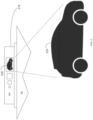
FIG 1 is a diagrammatic view of an autonomous vehicle according to an embodiment of the present invention; -
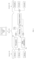
FIG 2A is a diagrammatic view of one embodiment of the various systems included within the autonomous vehicle ofFIG 1 according to an embodiment of the present invention; -
FIG 2B is a diagrammatic view of another embodiment of the various systems included within the autonomous vehicle ofFIG 1 according to an embodiment of the present invention; -
FIG 3 is a diagrammatic view of another embodiment of the various systems included within the autonomous vehicle ofFIG 1 according to an embodiment of the present invention; -
FIGS. 4A-4C are diagrammatic views of a status indication system of the autonomous vehicle ofFIG 1 according to an embodiment of the present invention; -
FIG 5 is a flowchart of one implementation of a status indication process executed on one or more systems of the autonomous vehicle ofFIG 1 according to an embodiment of the present invention; -
FIGS. 6A-6C are diagrammatic views of the status indication system of the autonomous vehicle ofFIG 1 according to an embodiment of the present invention; -
FIG 7 is a flowchart of another implementation of a status indication process executed on one or more systems of the autonomous vehicle ofFIG 1 according to an embodiment of the present invention; -
FIG 8 is diagrammatic view of the status indication system of the autonomous vehicle ofFIG 1 according to an embodiment of the present invention; and -
FIGS. 9A-9B are diagrammatic views of the status indication system of the autonomous vehicle ofFIG 1 according to an embodiment of the present invention. - Like reference symbols in the various drawings indicate like elements.
- Referring to
FIG 1 , there is shownautonomous vehicle 10. As is known in the art, an autonomous vehicle (e.g. autonomous vehicle 10) is a vehicle that is capable of sensing its environment and moving with little or no human input. Autonomous vehicles (e.g. autonomous vehicle 10) may combine a variety of sensor systems to perceive their surroundings, examples of which may include but are not limited to radar, computer vision, LIDAR, GPS, odometry, temperature and inertia, wherein such sensor systems may be configured to interpret lanes and markings on a roadway, street signs, stoplights, pedestrians, other vehicles, roadside objects, hazards, etc. -
Autonomous vehicle 10 includes a plurality of sensors (e.g. sensors 12), a plurality of electronic control units (e.g. ECUs 14) and a plurality of actuators (e.g. actuators 16). Accordingly,sensors 12 withinautonomous vehicle 10 may monitor the environment in whichautonomous vehicle 10 is operating, whereinsensors 12 may providesensor data 18 toECUs 14.ECUs 14 may processsensor data 18 to determine the manner in whichautonomous vehicle 10 should move.ECUs 14 may then providecontrol data 20 to actuators 16 so thatautonomous vehicle 10 may move in the manner decided byECUs 14. For example, a machinevision sensor included withinsensors 12 may "read" a speed limit sign stating that the speed limit on the road on whichautonomous vehicle 10 is traveling is now 35 miles an hour. This machine vision sensor included withinsensors 12 may providesensor data 18 toECUs 14 indicating that the speed on the road on whichautonomous vehicle 10 is traveling is now 35 mph. Upon receivingsensor data 18,ECUs 14 may processsensor data 18 and may determine that autonomous vehicle 10 (which is currently traveling at 45 mph) is traveling too fast and needs to slow down. Accordingly,ECUs 14 may providecontrol data 20 toactuators 16, whereincontrol data 20 may e.g. apply the brakes ofautonomous vehicle 10 or eliminate any actuation signal currently being applied to the accelerator (thus allowingautonomous vehicle 10 to coast until the speed ofautonomous vehicle 10 is reduced to 35 mph). - As would be imagined, since
autonomous vehicle 10 is being controlled by the various electronic systems included therein (e.g. sensors 12,ECUs 14 and actuators 16), the potential failure of one or more of these systems should be considered when designingautonomous vehicle 10 and appropriate contingency plans are employed. - For example and referring also to
FIG 2A , the various ECUs (e.g., ECUs 14) that are included withinautonomous vehicle 10 are compartmentalized so that the responsibilities of the various ECUs (e.g., ECUs 14) may be logically grouped. For example,ECUs 14 includesautonomy control unit 50 that receivessensor data 18 fromsensors 12. -
Autonomy control unit 50 is configured to perform various functions. For example,autonomy control unit 50 receives and processes exteroceptive sensor data (e.g., sensor data 18), mestimates the position ofautonomous vehicle 10 within its operating environment, calculates a representation of the surroundings ofautonomous vehicle 10, computes safe trajectories forautonomous vehicle 10, and commands the other ECUs (in particular, a vehicle control unit) to causeautonomous vehicle 10 to execute a desired maneuver.Autonomy control unit 50 includes substantial compute power, persistent storage, and memory. - Accordingly,
autonomy control unit 50processes sensor data 18 to determine the manner in whichautonomous vehicle 10 should be operating.Autonomy control unit 50 then providesvehicle control data 52 tovehicle control unit 54, whereinvehicle control unit 54 then processesvehicle control data 52 to determine the manner in which the individual control systems (e.g. powertrain system 56,braking system 58 and steering system 60) should respond in order to achieve the trajectory defined byautonomous control unit 50 withinvehicle control data 52. -
Vehicle control unit 54 is configured to control other ECUs included withinautonomous vehicle 10. For example,vehicle control unit 54 controls the steering, powertrain, and brake controller units. For example,vehicle control unit 54 provides:powertrain control signal 62 topowertrain control unit 64;braking control signal 66 tobrakingcontrol unit 68; andsteering control signal 70 tosteering control unit 72. -
Powertrain control unit 64 processespowertrain control signal 62 so that the appropriate control data (commonly represented by control data 20) are provided topowertrain system 56. Additionally,braking control unit 68 processes braking control signal66 so that the appropriate control data (commonly represented by control data 20) are provided tobraking system 58. Further, steeringcontrol unit 72 processes steeringcontrol signal 70 so that the appropriate control data (commonly represented by control data 20) are provided tosteering system 60. -
Powertrain control unit 64 is configured to control the transmission (not shown) and engine / traction motor (not shown) withinautonomous vehicle 10; whilebrake control unit 68 is configured to control the mechanical / regenerative braking system (notshown) withinautonomous vehicle 10; andsteering control unit 72 is configured to control the steering column/ steering rack (not shown) withinautonomous vehicle 10. -
Autonomy control unit 50 is a highly complex computing system that provides extensive processing capabilities (e.g., a workstation-class computing system with multi-core processors, discrete co-processing units, gigabytes of memory, and persistent storage). In contrast,vehicle control unit 54 is a much simpler device that provides processing power equivalent to the other ECUs included within autonomous vehicle 10 (e.g., acomputing system having a modest microprocessor (with a CPU frequency of less than 200 megahertz), less than 1 megabyte of system memory, and no persistent storage). Due to these simpler designs,vehicle control unit 54 has greater reliability and durability thanautonomy control unit 50. - To further enhance redundancy and reliability, one or more of the ECUs (ECUs 14) included within
autonomous vehicle 10 is configured in a redundant fashion. For example and referring also toFIG 2B , there is shown one implementation ofECUs 14 wherein a plurality of vehicle control units are utilized. For example, this particular implementation is shown to include two vehicle control units, namely a first vehicle control unit (e.g., vehicle control unit 54) and a second vehicle control unit (e.g., vehicle control unit 74). - In this particular configuration, the two vehicle control units (e.g.
vehicle control units 54, 74) are configured in various ways. For example, the two vehicle control units (e.g.vehicle control units 54, 74) are configured in an active - passive configuration, wherein e.g.vehicle control unit 54 performs the active role of processingvehicle control data 52 whilevehicle control unit 74 assumes a passive role and is essentially in standby mode. In the event of a failure ofvehicle control unit 54,vehicle control unit 74 transitions from a passive role to an active role and assumes the role of processingvehicle control data 52. Alternatively, the two vehicle control units (e.g.vehicle control units 54, 74) are configured in an active - active configuration, wherein e.g. bothvehicle control unit 52 andvehicle control unit 74 perform the active role of processing vehicle control data 54 (e.g. divvying up the workload), wherein in the event of a failure of eithervehicle control unit 54 orvehicle controlunit 74, the surviving vehicle control unit may process all ofvehicle control data 52. - While
FIG 2B illustrates one example of the manner in which the various ECUs (e.g. ECUs 14) included withinautonomous vehicle 10 are configured in a redundant fashion, this is for illustrative purposes only and is not intended to be a limitation of this invention, as other configurations are possible and are considered to be within the scope of this invention. For example,autonomous control unit 50 is configured in a redundant fashion, wherein a second autonomous control unit (not shown) is included withinautonomous vehicle 10 and is configured in an active - passive or active - active fashion. Further, it is foreseeable that one or more of the sensors (e.g., sensors 12) and/or one or more of the actuators (e.g. actuators 16) may be configured in a redundant fashion. Accordingly, it is understood that the level of redundancy achievable with respect toautonomous vehicle 10 mayonly be limited by the design criteria and budget constraints ofautonomous vehicle 10. - Referring also to
FIG 3 , the various ECUs ofautonomous vehicle 10 are grouped/ arranged/ configured to effectuate various functionalities. - For example, one or more of
ECUs 14 are configured to effectuate I formperception subsystem 100. whereinperception subsystem 100 is configured to process data from onboard sensors (e.g., sensor data 18) to calculate concise representations of objects of interest near autonomous vehicle 10 (examples of which includes but are not limited to other vehicles, pedestrians, traffic signals, traffic signs, road markers, hazards, etc.) and to identify environmental features that assist in determining the location ofautonomous vehicle 10. Further, one or more ofECUs 14 are configured to effectuate / formstate estimation subsystem 102, whereinstate estimation subsystem 102 is configured to process data from onboard sensors (e.g., sensor data 18) to estimate the position, orientation, and velocity ofautonomous vehicle 10 within its operating environment. Additionally, one or more ofECUs 14 are configured to effectuate I form planningsubsystem 104, whereinplanning subsystem 104 are configured to calculate a desired vehicle trajectory (usingperception output 106 and state estimation output 108). Further still, one or more ofECUs 14 are configured to effectuate I formtrajectory control subsystem 110, whereintrajectory control subsystem 110 usesplanning output 112 and state estimation output 108 (in conjunction with feedback and/or feedforward control techniques) to calculate actuator commands (e.g., control data 20) that causeautonomous vehicle 10 to execute its intended trajectory within it operating environment. - For redundancy purposes, the above-described subsystems are distributed across various devices (e.g.,
autonomy control unit 50 andvehicle control units 54, 74). Additionally / alternatively and due to the increased computational requirements,perception subsystem 100 andplanning subsystem 104 are located almost entirely withinautonomy control unit 50, which (as discussed above) has much more computational horsepower thanvehicle control units state estimation subsystem 102 andtrajectory control subsystem 110 are located entirely onvehicle control units vehicle control units vehicle control units autonomy control unit 50. However, the location ofstate estimation subsystem 102 andtrajectory controlsubsystem 110 are of critical importance in the design of any contingency planning architecture, as the location of these subsystems determine how contingency plans arecalculated, transmitted, and/or executed. - Referring also to
FIGS. 4A ,4B ,4C , there is shown an exterior view ofautonomousvehicle 10, whereinautonomous vehicle 10 includesstatus indication system 200 for conveying status information concerning a moveable vehicle (e.g., autonomous vehicle 10). -
Status indication system 200 includes an interface system (e.g., interface system202) configured to receive perception information (e.g., perception information 204) concerning one or more objects (e.g., objects 206, 208, 210, 212) proximate the moveable vehicle (e.g., autonomous vehicle 10). The one or more objects (e.g., objects 206, 208, 210, 212) proximate the moveable vehicle (e.g., autonomous vehicle 10include one or more of: - pedestrians (e.g., objects 208, 210, 212) proximate the moveable vehicle (e.g., autonomous vehicle 10), such as people that are walking / passing by
autonomous vehicle 10. - third-party vehicles (e.g., object 206) proximate the moveable vehicle (e.g., autonomous vehicle 10), such as other vehicles that are driving / stopped near
autonomous vehicle 10. - As discussed above,
sensors 12 withinautonomous vehicle 10 monitors the environment in whichautonomous vehicle 10 is operating, whereinsensors 12 providesensor data 18 toECUs 14 that may be processed to determine the manner in whichautonomous vehicle 10 should operate.Interface system 202 is configured to interface with sensors 12 (generally) and one of more machine vision sensors (specifically) included within the moveable vehicle (e.g., autonomous vehicle 10). Example of such machine vision sensors include but are not limited to LIDAR system. - As is known in the art, LIDAR is a method for determining ranges (variable distance) by targeting an object with a laser and measuring the time for the reflected light to return to the receiver. Lidar is also be used to make digital 3-D representations of areas on the earth's surface and ocean bottom, due to differences in laser return times, and by varying laser wavelengths. It has terrestrial, airborne, and mobile applications. Lidar is an acronym of "light detection and ranging" or "laser imaging, detection, and ranging". Lidar sometimes is called 3-D laser scanning, a special combination of a 3-D scanning and laser scanning. Lidar iscommonly used to make high-resolution maps, with applications in surveying, geodesy, geomatics, archaeology, geography, geology, geomorphology, seismology, forestry, atmospheric physics, laser guidance, airborne laser swath mapping (ALSM), and laser altimetry. The technology is also used in control and navigation for some autonomous cars.
-
Status indication system 200 includes a processing system (e.g., processing system 214) configured to process the perception information (e.g., perception information 204) to generate proximate object display information (e.g., proximate object display information 216).Processing system 214 is configured in various fashions. One example ofprocessing system 214 includes a stand-alone processing system that includes one or more processors (not shown) and one or more memory architectures (not shown). Another example ofprocessing system 214 includes a portion ofECUs 14.Processing system 214 is coupled to a storage device (e.g., storage device 114). Examples ofstoragedevice 114 include but are not limited to: a hard disk drive; a RAID device; a random- access memory (RAM); a read-only memory (ROM); and all forms of flash memory storage devices.Status indication system 200 includes a visual display system (e.g., visual display system 218) configured to render the proximate object display information (e.g., proximate object display information 216). As will be discussed below in greater detail, the visual display system (e.g., visual display system 218) is configured to convey the status information concerningautonomous vehicle 10 in a visual fashion that is easily understandable to people proximateautonomous vehicle 10. - Additionally, the interface system (e.g., interface system 202) is configured to receive moveable vehicle status information (e.g., moveable vehicle status information 220). As stated above,
sensors 12 withinautonomous vehicle 10 monitors the environment in whichautonomous vehicle 10 is operating, whereinsensors 12 may providesensor data 18 toECUs 14. Accordingly, the interface system (e.g., interface system 202) obtains such moveable vehicle status information (e.g., moveable vehicle status information 220) fromECUs 14. - Accordingly, the moveable vehicle status information (e.g., moveable vehicle status information 220) identifies one or more of the following:
- Whether the moveable vehicle is decelerating;
- Whether the moveable vehicle is accelerating;
- Whether the moveable vehicle is stationary; and
- Whether the moveable vehicle is turning:
- The processing system (e.g., processing system 214) is configured to process the moveable vehicle status information (e.g., moveable vehicle status information 220) to generate vehicle status display information (e.g., vehicle status display information 222), wherein the visual display system (e.g., visual display system 218) is configured to render the vehicle status display information (e.g., vehicle status display information 222). As will be discussed below in greater detail, the visual display system (e.g., visual display system 218) is configured to convey the status information concerning
autonomous vehicle 10 in a visual fashion that is easily understandable to people proximateautonomous vehicle 10. - The visual display system (e.g., visual display system 218) is configured to bemounted on a roof (e.g., roof 224) of the moveable vehicle (e.g., autonomous vehicle 10). The visual display system (e.g., visual display system 218) is configured in various fashions, all of which are considered to be within the scope of this invention.
- Cylindrical: The visual display system (e.g., visual display system 218) can be a cylindrical visual display system (as shown in
FIGS. 4A-4B ). Whenvisual display system 218 is configured in a cylindrical fashion,visual display system 218 includes: an illuminated portion (e.g., illumined portion 226); and a non-illuminated portion (non-illuminated portion 228) positioned between the illuminated portion (e.g., illumined portion 226) and the roof (e.g.,roof 224) of the moveable vehicle (e.g., autonomous vehicle 10), thus providing a "hovering" appearance with respect to the roof (e.g., roof 224) of the moveable vehicle (e.g., autonomous vehicle 10). - Disk-Shaped: The visual display system (e.g., visual display system 218) can be a disk-shaped visual display system (as shown in
FIG 4C ). Whenvisual display system 218 is configured in a disk-shaped fashion,visual display system 218 is generally illuminated proximate the roof (e.g., roof 224) of the moveable vehicle (e.g., autonomous vehicle 10), thus providing a lower profile that may be desirable when used on higher profile vehicles (such as SUVs and vans). - Regardless of configuration, the visual display system (e.g., visual display system 218) is a 360 degree visual display system, thus conveying the status information concerning
autonomous vehicle 10 in a visual fashion regardless of where the people are positioned proximateautonomous vehicle 10. - While the visual display system (e.g., visual display system 218) is described aboveas being mounted on a roof (e.g., roof 224) of the moveable vehicle (e.g., autonomous vehicle 10), this is for illustrative purposes only and is not intended to be a limitation of this invention, as other configurations are possible and are considered to be within the scope of this invention. For example, the visual display system (e.g., visual display system 218) is integrated into the moveable vehicle (e.g., autonomous vehicle 10) in various fashions. Accordingly, the visual display system (e.g., visual display system 218) is a portion of (or incorporated within) a window (e.g., window 230) of the moveable vehicle (e.g., autonomous vehicle 10).
- As discussed above, the visual display system (e.g., visual display system 218) is configured to convey status information concerning
autonomous vehicle 10 in a visual fashion that is easily understandable to people proximateautonomous vehicle 10. - Referring also to
FIG 5 and in order to convey such status information in such a visual fashion,processing system 214 executesstatus indication process 250. As discussedabove,processing system 214 is configured in various fashions, examples of which may include but are not limited to: - as a stand-alone processing system that includes one or more processors (not shown) and one or more memory architectures (not shown); and/or
- as a portion of
ECUs 14. - The instruction sets and subroutines of
status indication process 250, which is stored onstorage device 114 coupled toECUs 14, is executed by one or more processors (not shown) and one or more memory architectures (not shown) included withinECUs 14. Examples ofstorage device 114 includes but are not limited to: a hard disk drive; a RAID device; a random-access memory (RAM); a read-only memory (ROM); and all forms of flash memory storage devices. -
Status indication process 250 is executed on a single ECU or is executedcollaboratively across multiple ECUs. For example,status indication process 250 is executed solely byautonomy control unit 50,vehicle control unit 54 or vehicle control unit 74.Alternatively,status indication process 250 is executed collaboratively across the combination ofautonomy control unit 50,vehicle control unit 54 andvehicle control unit 74. Accordingly and in the latter configuration, in the event of a failure of one ofautonomy controlunit 50,vehicle control unit 54 orvehicle control unit 74, the surviving control unit(s) continues to executestatus indication process 250. -
Status indication process 250 may monitor 252 one or more machine vision sensors(e.g.,sensors 12 generally and a LIDAR sensor specifically) to obtain perception information (e.g., perception information 204) concerning one or more pedestrians (e.g., objects 208, 210, 212) proximate an autonomous vehicle (e.g., autonomous vehicle 10).Perception information 204 is a three-dimensional image that generally identifies all objects in geographic proximity ofautonomous vehicle 10. -
Status indication process 250 identifies 254 one or more humanoid shapes within the perception information (e.g., perception information 204), thus defining one or more detected humanoid shapes. When identifying 254 one or more humanoid shapes within the perception information (e.g., perception information 204),status indication process 250 compares 256 one or more defined humanoid shapes (e.g., defined humanoid shapes 232) to one or more unidentified objects within the perception information (e.g., perception information 204) to identify one or more humanoid shapes within the perception information (e.g., perception information 204). - Defined humanoid shapes 232 are manually-defined (e.g., via a designer / programmer of status indication process 250) and/or automatically-defined (e.g., via Artificial Intelligence/ Machine Learning (AI/ML) in a fashion similar to the manner in which AI/ML can identify human faces within photographs). Generally speaking,
perception information 204 is a three-dimensional image that generally identifies a plurality of unidentified objects that are in geographic proximity ofautonomous vehicle 10. Accordingly,status indication process 250 may compare 256 definedhumanoid shapes 232 to one or more unidentified objects within the perception information (e.g., perception information 204) to identify one or more humanoid shapes within the perception information (e.g., perception information 204). - Once the humanoid shapes are identified 254 within
perception information 204,status indication process 250 generates 258 proximate object display information (e.g., proximate object display information 216) that locates the one or more detected humanoid shapes with respect to the autonomous vehicle (e.g., autonomous vehicle 10).Status indication process 250 then renders 260 the proximate object display information (e.g., proximate object display information 216) on a visual display system (e.g., visual display system 218), thus confirming the perception of the one or more pedestrians (e.g., objects 208, 210, 212) by the autonomous vehicle (e.g., autonomous vehicle 10). - For example,
FIG 6A illustrates a situation in which two pedestrians (e.g.,pedestrians 300, 302) are standing stationary proximate the side ofautonomous vehicle 10. Accordingly, proximateobject display information 216 locates the one or more detected humanoid shapes (e.g.,pedestrians 300, 302) with respect toautonomous vehicle 10. Further,visual display system 218 ofstatus indication system 200 conveys status information concerningautonomous vehicle 10 in a visual fashion that is easily understandable to people (e.g.,pedestrians 300, 302) proximateautonomous vehicle 10. Accordingly,visual display system 218 renders a first indicator (e.g., indicator 304) that is pointing to (or corresponds with)pedestrian 300. Aspedestrian 300 is stationary,indicator 304 is stationary withinvisual display system 302. Further,visual display system 218 renders a second indicator (e.g., indicator 306) that is pointing to (or corresponds with)pedestrian 302. As pedestrian 302is stationary,indicator 306 may be stationary withinvisual display system 302. Further,FIG 6B illustrates a situation in which one pedestrian (e.g.,pedestrian 300, 308) is standing stationary proximate the front ofautonomous vehicle 10. Accordingly, proximateobject display information 216 locates the one or more detected humanoid shapes (e.g., pedestrian 308) with respect toautonomous vehicle 10. Further,visual display system 218 ofstatus indication system 200 conveys status information concerningautonomous vehicle 10 in a visual fashion that is easily understandable to people (e.g., pedestrian 308) proximateautonomous vehicle 10. Accordingly,visual display system 218 renders an indicator (e.g., indicator 310) that is pointing to (or corresponds with)pedestrian 308. Aspedestrian 308 is stationary,indicator 310 is stationary withinvisual display system 302. Further, aspedestrian 310 is in the path of (i.e., obstructing)autonomous vehicle 10,indicator 310 provides instructions topedestrian 308 in the form of e.g., the leftward-facing arrow that is askingpedestrian 308 to move to the left and out of the path ofautonomous vehicle 10. - The proximate object display information (e.g., proximate object display information 216) includes dynamic proximate object display information (e.g., proximate object display information 216) that changes as the location of the one or more detected humanoid shapes changes with respect to the autonomous vehicle (e.g., autonomous vehicle 10). Accordingly and when rendering 260 the proximate object display information (e.g., proximate object display information 216) on a visual display system (e.g., visual display system 218),
status indication process 250 renders 262 the dynamic proximate object display information (e.g., proximate object display information 216) on the visual display system (e.g., visual display system 218), thus dynamically confirming the perception of the one or more pedestrians (e.g., objects 208, 210, 212) by the autonomous vehicle (e.g., autonomous vehicle 10). - For example,
FIG 6C illustrates a situation in which two pedestrians (e.g.,pedestrians 312, 314) are walking in front ofautonomous vehicle 10. Accordingly, proximateobject display information 216 locates the one or more detected humanoid shapes (e.g.,pedestrians 312, 314) with respect toautonomous vehicle 10. Further,visual display system 218 ofstatus indication system 200 conveys status information concerningautonomous vehicle 10 in a visual fashion that is easily understandable to people (e.g.,pedestrians 312, 314) proximateautonomous vehicle 10. Accordingly,visual display system 218 renders a first indicator (e.g., indicator 316) that is pointing to (or corresponds with)pedestrian 312. Aspedestrian 312 is moving right to left,indicator 316 also moves right to left withinvisual display system 302. Further,visual display system 218 renders a second indicator (e.g., indicator 318) that is pointing to (or corresponds with)pedestrian 314. Aspedestrian 314 is moving left to right,indicator 318 also moves left to right withinvisual display system 302. - In a fashion similar to the manner in which
status indication process 10 tracks pedestrians proximate an autonomous vehicle (e.g., autonomous vehicle 10),status indication process 10 also tracks vehicles proximate an autonomous vehicle (e.g., autonomous vehicle10). For example and referring also toFIG 7 ,status indication process 250 monitors350 one or more machine vision sensors (e.g.,sensors 12 generally and a LIDAR sensor specifically) to obtain perception information (e.g., perception information 204) concerning one or more third-party vehicles (e.g., object 206) proximate an autonomous vehicle (e.g., autonomous vehicle 10). -
Status indication process 250 identifies 352 one or more vehicle shapes within the perception information (e.g., perception information 204), thus defining one or more detected vehicles shapes. When identifying 352 one or more vehicle shapes within the perception information (e.g., perception information 204),status indication process 250 compares 354 one or more defined vehicle shapes (e.g., defined vehicle shapes 234) to one or more unidentified objects within the perception information (e.g., perception information 204) to identify one or more vehicle shapes within the perception information (e.g., perception information 204). - Defined vehicle shapes 234 are manually-defined (e.g., via a designer / programmer of status indication process 250) and/or automatically-defined (e.g., via Artificial Intelligence/ Machine Learning (AI/ML) in a fashion similar to the manner in which AI/ML can identify vehicles within photographs). Generally speaking,
perception information 204 is a three-dimensional image that generally identifies a plurality of unidentified objects that are in geographic proximity ofautonomous vehicle 10. Accordingly,status indication process 250 compares 354 defined vehicle shapes 234 to one or more unidentified objects within the perception information (e.g., perception information 204) to identify one or more vehicle shapes within the perception information (e.g., perception information 204). - Once the vehicle shapes are identified 352 within
perception information 204,status indication process 250 generates 356 proximate object display information (e.g., proximateobject display information 216) that locates the one or more detected vehicles shapes with respect to the autonomous vehicle (e.g., autonomous vehicle 10).Status indication process 250 then renders 358 the proximate object display information (e.g., proximate object display information 216) on a visual display system (e.g., visual display system 218), thus confirming the perception of the one or more third-party vehicles (e.g., object 206) by the autonomous vehicle (e.g., autonomous vehicle 10). - The proximate object display information (e.g., proximate object displayinformation 216) includes dynamic proximate object display information (e.g., proximateobject display information 216) that changes as the location of the one or more detected vehicle shapes changes with respect to the autonomous vehicle (e.g., autonomous vehicle 10). Accordingly and when rendering 358 the proximate object display information (e.g., proximate object display information 216) on a visual display system (e.g., visual display system 218),
status indication process 250 renders 360 the dynamic proximate object display information (e.g., proximate object display information 216) on the visual display system (e.g.,visual display system 218), thus dynamically confirming the perception of the one or more third-party vehicles (e.g., object 206) by the autonomous vehicle (e.g., autonomous vehicle 10). - As shown on
FIGS. 6A, 6B, 6C ,visual display system 218 renders various indicators (e.g.,indicators indicators indicators pedestrians FIG 8 , whenstatus indication process 10 is tracking vehicles proximateautonomous vehicle 10,visual display system 218 renders various indicators (e.g., indicator 320) that includes e.g., a "car figure" that is indicative of the indicator (e.g., indicator 320) pointing to (or corresponds with) a vehicle (e.g., third-party vehicle 322). - As discussed above, the interface system (e.g., interface system 202) is configured to receive moveable vehicle status information (e.g., moveable vehicle status information 220), wherein this moveable vehicle status information (e.g., moveable vehicle status information 220) identifies one or more of the following:
- Whether the moveable vehicle is decelerating;
- Whether the moveable vehicle is accelerating;
- Whether the moveable vehicle is stationary; and
- Whether the moveable vehicle is turning:
- The processing system (e.g., processing system 214) is configured to process the moveable vehicle status information (e.g., moveable vehicle status information 220) to generate vehicle status display information (e.g., vehicle status display information 222), wherein the visual display system (e.g., visual display system 218) is configured to render the vehicle status display information (e.g., vehicle status display information 222).
- Accordingly and as shown in
FIG 9A ,proximate object portion 350 ofvisual display system 218 is configured to track pedestrians proximate an autonomous vehicle (e.g., autonomous vehicle 10). Further,status portion 352 ofvisual display system 218 is configured to render vehiclestatus display information 222. For example,status portion 352 may include: - "turning left"
section 354, which may illuminate whenautonomous vehicle 10 is planning on turning left. - "turning right"
section 356, which may illuminate whenautonomous vehicle 10 is planning on turning right. -
status section 358, which may indicate whetherautonomous vehicle 10 is:- I. cruising at a steady state by e.g., displaying solid white,
- II. accelerating by e.g., displaying a color that varies from white to intense green,
- III. decelerating by e.g., displaying a color that varies from white to intense red, and
- IV. stationary by e.g., displaying solid red.
- Additionally and as shown in
FIG 9B ,proximate object portion 350 ofvisual display system 218 is configured to track third-party vehicles proximate an autonomous vehicle (e.g., autonomous vehicle 10). Again,status portion 352 ofvisual display system 218 is configured to render vehicle status display information 222 (as described above). - As will be appreciated by one skilled in the art, the present invention may be embodied as a method, a system, or a computer program product. Accordingly, the present invention takes the form of an entirely hardware embodiment, an entirely software embodiment (including firmware, resident software, micro-code, etc.) or an embodiment combining software and hardware aspects that all generally be referred to herein as a "circuit," "module" or "system." Furthermore, the present invention takes the form of a computer program product on a computer-usable storage medium having computer-usable program code embodied in the medium.
- Any suitable computer usable or computer readable medium is utilized. The computer-usable or computer-readable medium is, for example but not limited to, an electronic, magnetic, optical, electromagnetic, infrared, or semiconductor system, apparatus, device, or propagation medium. More specific examples (a non-exhaustive list) of the computer-readable medium includes the following: an electrical connection having one or more wires, a portable computer diskette, a hard disk, a random access memory (RAM), a read-only memory (ROM), an erasable programmable read-only memory (EPROM or Flash memory), an optical fiber, a portable compact disc read-only memory (CD-ROM), an optical storage device, a transmission media such as those supporting the Internet or an intranet, or a magnetic storage device. The computer-usable or computer-readable medium also is paper or another suitable medium upon which the program is printed, as the program can be electronically captured, via, for instance, optical scanning of the paper or other medium, then compiled, interpreted, or otherwise processed in a suitable manner, if necessary, and then stored in a computer memory. In the context of this document, a computer-usable or computer-readable medium is any medium that can contain, store, communicate, propagate, or transport the program for use by or in connection with the instruction execution system, apparatus, or device. The computer-usable medium includes a propagated data signal with the computer-usable program code embodied therewith, either in baseband or as part of a carrier wave. The computer usable program code is transmitted using any appropriate medium, including but not limited to the Internet, wireline, optical fiber cable, RF, etc.
- Computer program code for carrying out operations of the present invention is written in an object oriented programming language such as Java, Smalltalk, C++ or the like. However, the computer program code for carrying out operations of the present invention is be written in conventional procedural programming languages, such as the"C" programming language or similar programming languages. The program code executes entirely on the user's computer, partly on the user's computer, as a stand-alone software package, partly on the user's computer and partly on a remote computer or entirely on the remote computer or server. In the latter scenario, the remote computer is connected to the user's computer through a local area network I a wide area network I the Internet (e.g., network14).
- The present invention is described with reference to flowchart illustrations and/or block diagrams of methods, apparatus (systems) and computer program products according to embodiments of the invention. It will be understood that each block of the flowchart illustrations and/or block diagrams, and combinations of blocks in the flowchart illustrations and/or block diagrams, are implemented by computer program instructions. These computer program instructions is provided to a processor of a general purpose computer/ special purpose computer / other programmable data processing apparatus, such that the instructions, which execute via the processor of the computer or other programmable data processing apparatus, create means for implementing the functions/acts specified m the flowchart and/or block diagram block or blocks.
- These computer program instructions are also be stored in a computer-readable memory that directs a computer or other programmable data processing apparatus to function in a particular manner, such that the instructions stored in the computer-readable memory produce an article of manufacture including instruction means which implement the function/act specified in the flowchart and/or block diagram block or blocks.
- The computer program instructions are also be loaded onto a computer or other programmable data processing apparatus to cause a series of operational steps to be performed on the computer or other programmable apparatus to produce a computer-implemented processsuch that the instructions which execute on the computer or other programmable apparatus provide steps for implementing the functions/acts specified in the flowchart and/or block diagram block or blocks.
- The flowcharts and block diagrams in the figures illustrates the architecture, functionality, and operation of possible implementations of systems, methods and computer program products according to various embodiments of the present invention. In this regard, each block in the flowchart or block diagrams represents a module, segment, or portion of code, which comprises one or more executable instructions for implementing the specified logical function(s). It should also be noted that, in some alternative implementations, the functions noted in the block occurs out of the order noted in the figures. For example, two blocks shown in succession are, in fact, be executed substantially concurrently, or the blocks are sometimes be executed in the reverse order, depending upon the functionality involved. It will also be noted that each block of the block diagrams and/or flowchart illustrations, and combinations of blocks in the block diagrams and/or flowchart illustrations, are implemented by special purpose hardware-based systems that perform the specified functions or acts, or combinations of special purpose hardware and computer instructions.
- The terminology used herein is for the purpose of describing particular embodiments only and is not intended to be limiting of the invention. As used herein, the singular forms "a", "an" and "the" are intended to include the plural forms as well, unless the context clearly indicates otherwise. It will be further understood that the terms "comprises" and/or "comprising," when used in this specification, specify the presence of stated features, integers, steps, operations, elements, and/or components, but do not preclude the presence or addition of one or more other features, integers, steps, operations, elements, components, and/or groups thereof.
Claims (9)
- A computer-implemented method, to be executed on a computing device, the computer-implemented method for an autonomous vehicle (10) comprising:monitoring one or more machine vision sensors (12) included within the autonomous vehicle (10) to obtain perception information concerning one or more pedestrians (300, 301, 308, 312, 314) proximate the autonomous vehicle (10);identifying one or more humanoid shapes (232) within the perception information, thus defining one or more detected humanoid shapes (232);generating proximate object display information (216) that locates the one or more detected humanoid shapes (232) with respect to the autonomous vehicle; andrendering the proximate object display information (216) on a visual display system (218) of the autonomous vehicle, thus confirming the perception of the one or more pedestrians (300, 301, 308, 312, 314) by the autonomous vehicle (10),wherein the rendering on the visual display system (218) includes rendering at least an indicator (304) that is pointing to a stationary pedestrian (308), wherein at least the indicator (304) is stationary within visual display system (218), and wherein the rendering includes rendering instructions on the visual display system (218) of the autonomous vehicle (10), as a pedestrian (308) is in the path of the autonomous vehicle (10) is detected, an indicator (310) providing instructions to pedestrian (308) in the form of an arrow that is asking pedestrian (308) to move out of the path of autonomous vehicle (10), and wherein the rendering on the visual display system (218) includes rendering a first indicator (316) that is pointing to or corresponds with a first pedestrian (312) and as the first pedestrian (312) is moving right to left, the first indicator (316) also moves right to left within visual display system (302) and further, the rendering includes rendering a second indicator (318) that is pointing to or corresponds with a second pedestrian (314) and as the second pedestrian (314) is moving left to right, second indicator (318) also moves left to right within visual display system (302).
- The computer-implemented method of claim 1 wherein identifying one or more humanoid shapes (232) within the perception information includes:
Comparing one or more defined humanoid shapes (232) to one or more unidentified objects within the perception information to identify the one or more humanoid shapes (232) within the perception information. - The computer-implemented method of claim 1 wherein the one of more machine vision sensors (12) includes a LIDAR system.
- The computer-implemented method of claim 1 wherein the visual display system is configured to be mounted on a roof (224) of the autonomous vehicle (10).
- The computer-implemented method of claim 1 wherein the visual display system is a cylindrical visual display system.
- The computer-implemented method of claim 5 wherein the cylindrical visual display system includes:an illuminated portion; anda non-illuminated portion positioned between the illuminated portion and the roof (224) of the autonomous vehicle (10).
- The computer-implemented method of claim 1 wherein the visual display system is a 360 degree visual display system.
- A computer program product residing on a computer readable medium having a plurality of instructions stored thereon which, when executed by a processor, cause the processor to perform operations according to one of the claims 1 to 7.
- A computing system including a processor and memory configured to perform operations according to the method of one of the claims 1 to 7.
Applications Claiming Priority (2)
| Application Number | Priority Date | Filing Date | Title |
|---|---|---|---|
| US202063028953P | 2020-05-22 | 2020-05-22 | |
| PCT/US2021/033860 WO2021237201A1 (en) | 2020-05-22 | 2021-05-24 | Display system and method |
Publications (3)
| Publication Number | Publication Date |
|---|---|
| EP4153455A1 EP4153455A1 (en) | 2023-03-29 |
| EP4153455A4 EP4153455A4 (en) | 2024-01-31 |
| EP4153455B1 true EP4153455B1 (en) | 2025-07-09 |
Family
ID=78607787
Family Applications (3)
| Application Number | Title | Priority Date | Filing Date |
|---|---|---|---|
| EP21808338.4A Withdrawn EP4153453A4 (en) | 2020-05-22 | 2021-05-24 | DISPLAY SYSTEM AND METHOD |
| EP21807605.7A Pending EP4153452A4 (en) | 2020-05-22 | 2021-05-24 | Display system and method |
| EP21808623.9A Active EP4153455B1 (en) | 2020-05-22 | 2021-05-24 | Display system and method |
Family Applications Before (2)
| Application Number | Title | Priority Date | Filing Date |
|---|---|---|---|
| EP21808338.4A Withdrawn EP4153453A4 (en) | 2020-05-22 | 2021-05-24 | DISPLAY SYSTEM AND METHOD |
| EP21807605.7A Pending EP4153452A4 (en) | 2020-05-22 | 2021-05-24 | Display system and method |
Country Status (4)
| Country | Link |
|---|---|
| US (3) | US11756461B2 (en) |
| EP (3) | EP4153453A4 (en) |
| CN (3) | CN115803226B (en) |
| WO (3) | WO2021237201A1 (en) |
Families Citing this family (3)
| Publication number | Priority date | Publication date | Assignee | Title |
|---|---|---|---|---|
| EP4153453A4 (en) | 2020-05-22 | 2024-01-31 | Magna Electronics Inc. | DISPLAY SYSTEM AND METHOD |
| US20230106692A1 (en) * | 2021-10-06 | 2023-04-06 | Gm Cruise Holdings Llc | Reflective surface-based communications system for rideshare service vehicle |
| US11987266B2 (en) * | 2022-02-25 | 2024-05-21 | Hitachi Astemo, Ltd. | Distributed processing of vehicle sensor data |
Citations (1)
| Publication number | Priority date | Publication date | Assignee | Title |
|---|---|---|---|---|
| DE102018206087A1 (en) * | 2018-04-20 | 2019-10-24 | Volkswagen Aktiengesellschaft | Method for communicating a motor vehicle with a road user and motor vehicle for carrying out the method |
Family Cites Families (70)
| Publication number | Priority date | Publication date | Assignee | Title |
|---|---|---|---|---|
| GB2330679B (en) * | 1997-10-21 | 2002-04-24 | 911 Emergency Products Inc | Warning signal light |
| US7764808B2 (en) * | 2003-03-24 | 2010-07-27 | Siemens Corporation | System and method for vehicle detection and tracking |
| US7095318B1 (en) * | 2004-09-28 | 2006-08-22 | Solomon Bekhor | Enhanced vehicle advisory system to advise drivers of other vehicles and passengers in the vehicle of actions taken by the driver |
| US7496439B2 (en) * | 2005-10-17 | 2009-02-24 | Lang Mekra North America, Llc | Multifunction exterior display for a vehicle mirror |
| US8384531B2 (en) * | 2009-04-02 | 2013-02-26 | GM Global Technology Operations LLC | Recommended following distance on full-windshield head-up display |
| US7924146B2 (en) * | 2009-04-02 | 2011-04-12 | GM Global Technology Operations LLC | Daytime pedestrian detection on full-windscreen head-up display |
| US8977489B2 (en) * | 2009-05-18 | 2015-03-10 | GM Global Technology Operations LLC | Turn by turn graphical navigation on full windshield head-up display |
| US8509982B2 (en) | 2010-10-05 | 2013-08-13 | Google Inc. | Zone driving |
| US20120287277A1 (en) * | 2011-05-13 | 2012-11-15 | Koehrsen Craig L | Machine display system |
| US8195394B1 (en) * | 2011-07-13 | 2012-06-05 | Google Inc. | Object detection and classification for autonomous vehicles |
| US8718861B1 (en) * | 2012-04-11 | 2014-05-06 | Google Inc. | Determining when to drive autonomously |
| US9196164B1 (en) * | 2012-09-27 | 2015-11-24 | Google Inc. | Pedestrian notifications |
| JP6137001B2 (en) * | 2014-03-14 | 2017-05-31 | 株式会社デンソー | In-vehicle device |
| US9475422B2 (en) * | 2014-05-22 | 2016-10-25 | Applied Invention, Llc | Communication between autonomous vehicle and external observers |
| US10686976B2 (en) * | 2014-08-18 | 2020-06-16 | Trimble Inc. | System and method for modifying onboard event detection and/or image capture strategy using external source data |
| EP2993083B1 (en) * | 2014-09-04 | 2023-11-22 | Nokia Technologies Oy | Apparatus, method and computer program for controlling road user acknowledgement |
| GB2531084A (en) * | 2014-12-22 | 2016-04-13 | Daimler Ag | Vehicle configured for autonomous driving and method for operating a vehicle |
| US11247605B2 (en) * | 2015-04-10 | 2022-02-15 | Maxell, Ltd. | Image projection apparatus configured to project an image on a road surface |
| KR20170015112A (en) * | 2015-07-30 | 2017-02-08 | 삼성전자주식회사 | Autonomous Vehicle and Operation Method thereof |
| US10082797B2 (en) * | 2015-09-16 | 2018-09-25 | Ford Global Technologies, Llc | Vehicle radar perception and localization |
| US9694736B2 (en) * | 2015-09-30 | 2017-07-04 | Nissan North America, Inc. | Vehicle state indication system |
| CN115402191A (en) * | 2015-10-22 | 2022-11-29 | 日产自动车株式会社 | Vehicle notification device |
| US9804599B2 (en) * | 2015-11-04 | 2017-10-31 | Zoox, Inc. | Active lighting control for communicating a state of an autonomous vehicle to entities in a surrounding environment |
| WO2017079349A1 (en) | 2015-11-04 | 2017-05-11 | Zoox, Inc. | System for implementing an active safety system in an autonomous vehicle |
| US9983591B2 (en) * | 2015-11-05 | 2018-05-29 | Ford Global Technologies, Llc | Autonomous driving at intersections based on perception data |
| US9493158B2 (en) * | 2015-12-14 | 2016-11-15 | Thomas Danaher Harvey | Methods and devices for safe operation of undersize autonomous vehicles on public roads |
| CN108367708B (en) * | 2015-12-22 | 2021-03-12 | 株式会社小糸制作所 | Vehicle lighting device, vehicle and lighting control system |
| US10503985B2 (en) * | 2016-01-22 | 2019-12-10 | Nissan Motor Co., Ltd. | Pedestrian determination method and determination device |
| US10871655B2 (en) * | 2016-02-12 | 2020-12-22 | Maxell, Ltd. | Image display apparatus for vehicle |
| US9902311B2 (en) * | 2016-02-22 | 2018-02-27 | Uber Technologies, Inc. | Lighting device for a vehicle |
| JP6377655B2 (en) | 2016-02-29 | 2018-08-22 | 矢崎総業株式会社 | Vehicle display device |
| JP6788477B2 (en) * | 2016-03-10 | 2020-11-25 | パナソニック インテレクチュアル プロパティ コーポレーション オブ アメリカPanasonic Intellectual Property Corporation of America | Recognition result presentation device and recognition result presentation method |
| CN107176161B (en) * | 2016-03-10 | 2021-11-23 | 松下电器(美国)知识产权公司 | Recognition result presentation device, recognition result presentation method, and autonomous moving object |
| CN108885105B (en) * | 2016-03-15 | 2023-06-13 | 康多尔收购第二分公司 | System and method for providing vehicle awareness |
| US10055652B2 (en) * | 2016-03-21 | 2018-08-21 | Ford Global Technologies, Llc | Pedestrian detection and motion prediction with rear-facing camera |
| FR3049528B1 (en) * | 2016-04-05 | 2019-04-05 | Valeo Vision | METHOD FOR CONTROLLING AUTOMATIC DISPLAY OF A PICTOGRAM REPRESENTATIVE OF THE PRESENCE OF A PERTURBATION IN FRONT OF THE VEHICLE |
| US20170315771A1 (en) * | 2016-04-28 | 2017-11-02 | Toyota Motor Engineering & Manufacturing North America, Inc. | System and method for selectively displaying images in an autonomous vehicle |
| DE102016114247A1 (en) * | 2016-08-02 | 2018-02-08 | HELLA GmbH & Co. KGaA | Lighting device for a vehicle |
| CA2976543C (en) * | 2016-08-23 | 2026-02-10 | Vijyat Bhalla | System and method for augmented reality head up display for vehicles |
| DE102016220075A1 (en) * | 2016-10-14 | 2018-04-19 | Audi Ag | Motor vehicle and method for 360 ° field detection |
| JP6941120B2 (en) * | 2016-12-13 | 2021-09-29 | 株式会社小糸製作所 | Vehicle lighting systems, vehicle systems, vehicles and data communication systems |
| US10261513B2 (en) * | 2016-12-19 | 2019-04-16 | drive.ai Inc. | Methods for communicating state, intent, and context of an autonomous vehicle |
| US10318827B2 (en) * | 2016-12-19 | 2019-06-11 | Waymo Llc | Object detection neural networks |
| KR101752894B1 (en) * | 2016-12-23 | 2017-06-30 | 이인규 | Anti-collision system for getting on and off |
| US9953538B1 (en) * | 2017-01-17 | 2018-04-24 | Lyft, Inc. | Autonomous vehicle notification system |
| US20180276986A1 (en) * | 2017-03-22 | 2018-09-27 | Toyota Research Institute, Inc. | Vehicle-to-human communication in an autonomous vehicle operation |
| JP7026104B2 (en) | 2017-03-24 | 2022-02-25 | 日本板硝子株式会社 | Image sensor unit and image reader |
| US9904375B1 (en) | 2017-04-10 | 2018-02-27 | Uber Technologies, Inc. | LIDAR display systems and methods |
| US10279734B2 (en) * | 2017-06-16 | 2019-05-07 | GM Global Technology Operations LLC | Systems and methods for external warning by an autonomous vehicle |
| US10262528B2 (en) * | 2017-07-21 | 2019-04-16 | State Farm Mutual Automobile Insurance Company | Autonomous vehicle mode alert system for bystanders |
| JP6852638B2 (en) * | 2017-10-10 | 2021-03-31 | トヨタ自動車株式会社 | Self-driving vehicle dispatch system, self-driving vehicle, and vehicle dispatch method |
| US10606274B2 (en) * | 2017-10-30 | 2020-03-31 | Nio Usa, Inc. | Visual place recognition based self-localization for autonomous vehicles |
| US11710398B2 (en) * | 2018-01-26 | 2023-07-25 | Ford Global Technologies, Llc | Multipurpose vehicle lighting |
| JP7045879B2 (en) * | 2018-02-09 | 2022-04-01 | 株式会社小糸製作所 | Vehicle lighting system and vehicle |
| US10940802B2 (en) | 2018-07-18 | 2021-03-09 | Gentex Corporation | Vehicle display apparatus and mounting configuration |
| WO2020031915A1 (en) * | 2018-08-06 | 2020-02-13 | 株式会社小糸製作所 | Vehicle display system and vehicle |
| CN109334566B (en) * | 2018-08-31 | 2022-01-25 | 阿波罗智联(北京)科技有限公司 | Method, device, equipment and storage medium for providing feedback outside vehicle |
| US11345277B2 (en) * | 2018-10-16 | 2022-05-31 | GM Global Technology Operations LLC | Autonomous vehicle intent signaling |
| JP7205154B2 (en) * | 2018-10-16 | 2023-01-17 | トヨタ自動車株式会社 | Display device |
| DE102018008213B4 (en) * | 2018-10-17 | 2024-02-29 | Mercedes-Benz Group AG | Method for visualizing a transition over a road |
| US20200132489A1 (en) * | 2018-10-25 | 2020-04-30 | Ford Global Technologies, Llc | Methods and apparatus to facilitate navigation using a windshield display |
| KR102587258B1 (en) * | 2018-11-16 | 2023-10-11 | 현대모비스 주식회사 | Apparatus and method for transmitting driving information of vehicle |
| US10933803B2 (en) * | 2019-03-31 | 2021-03-02 | Gm Cruise Holdings Llc | Autonomous vehicle visual based communication |
| US10919439B2 (en) * | 2019-04-08 | 2021-02-16 | International Business Machines Corporation | Virtual vehicle protective fence |
| US20200353949A1 (en) | 2019-05-07 | 2020-11-12 | Optimus Ride, Inc. | Cost calculation system and method |
| JP7345128B2 (en) * | 2019-05-20 | 2023-09-15 | パナソニックIpマネジメント株式会社 | Pedestrian devices and traffic safety support methods |
| US20200380257A1 (en) * | 2019-05-29 | 2020-12-03 | Pony.ai, Inc | Autonomous vehicle object content presentation systems and methods |
| JP7349859B2 (en) * | 2019-09-18 | 2023-09-25 | 株式会社Subaru | External monitor device |
| US11548532B2 (en) * | 2020-04-07 | 2023-01-10 | DoorDash, Inc. | Systems for autonomous and automated delivery vehicles to communicate with third parties |
| EP4153453A4 (en) | 2020-05-22 | 2024-01-31 | Magna Electronics Inc. | DISPLAY SYSTEM AND METHOD |
-
2021
- 2021-05-24 EP EP21808338.4A patent/EP4153453A4/en not_active Withdrawn
- 2021-05-24 CN CN202180041218.XA patent/CN115803226B/en active Active
- 2021-05-24 US US17/328,115 patent/US11756461B2/en active Active
- 2021-05-24 US US17/328,140 patent/US11571970B2/en active Active
- 2021-05-24 WO PCT/US2021/033860 patent/WO2021237201A1/en not_active Ceased
- 2021-05-24 CN CN202180041205.2A patent/CN115916591B/en active Active
- 2021-05-24 EP EP21807605.7A patent/EP4153452A4/en active Pending
- 2021-05-24 WO PCT/US2021/033894 patent/WO2021237212A1/en not_active Ceased
- 2021-05-24 EP EP21808623.9A patent/EP4153455B1/en active Active
- 2021-05-24 WO PCT/US2021/033816 patent/WO2021237194A1/en not_active Ceased
- 2021-05-24 CN CN202180041204.8A patent/CN115734896B/en active Active
- 2021-05-24 US US17/328,066 patent/US11623523B2/en active Active
Patent Citations (1)
| Publication number | Priority date | Publication date | Assignee | Title |
|---|---|---|---|---|
| DE102018206087A1 (en) * | 2018-04-20 | 2019-10-24 | Volkswagen Aktiengesellschaft | Method for communicating a motor vehicle with a road user and motor vehicle for carrying out the method |
Also Published As
| Publication number | Publication date |
|---|---|
| WO2021237194A1 (en) | 2021-11-25 |
| CN115734896A (en) | 2023-03-03 |
| CN115916591B (en) | 2025-09-16 |
| CN115803226A (en) | 2023-03-14 |
| US11623523B2 (en) | 2023-04-11 |
| WO2021237212A1 (en) | 2021-11-25 |
| US11571970B2 (en) | 2023-02-07 |
| WO2021237201A1 (en) | 2021-11-25 |
| EP4153452A1 (en) | 2023-03-29 |
| US20210366272A1 (en) | 2021-11-25 |
| CN115734896B (en) | 2025-09-26 |
| CN115916591A (en) | 2023-04-04 |
| US20210362600A1 (en) | 2021-11-25 |
| EP4153455A4 (en) | 2024-01-31 |
| US20210366276A1 (en) | 2021-11-25 |
| EP4153455A1 (en) | 2023-03-29 |
| US11756461B2 (en) | 2023-09-12 |
| CN115803226B (en) | 2025-07-29 |
| WO2021237212A9 (en) | 2021-12-30 |
| EP4153453A1 (en) | 2023-03-29 |
| EP4153452A4 (en) | 2024-01-31 |
| EP4153453A4 (en) | 2024-01-31 |
Similar Documents
| Publication | Publication Date | Title |
|---|---|---|
| US11720116B1 (en) | Collision mitigation static occupancy grid | |
| US12565224B2 (en) | Vehicular control system having a plurality of electronic control units | |
| CN114442101B (en) | Vehicle navigation method, device, equipment and medium based on imaging millimeter wave radar | |
| US11493919B2 (en) | Vehicle including information presentation apparatus for presenting information to driver | |
| US20210271240A1 (en) | Fault-Tolerant Control of an Autonomous Vehicle with Multiple Control Lanes | |
| US9440647B1 (en) | Safely navigating crosswalks | |
| JP6736527B2 (en) | Predictive estimation for controlling vehicle speed | |
| US10156851B1 (en) | Determining the stationary state of detected vehicles | |
| US10509400B2 (en) | Control system for and control method of autonomous driving vehicle | |
| US11648872B2 (en) | Display device and display method for display device | |
| US11623523B2 (en) | Display system and method | |
| US12116007B2 (en) | Trajectory limiting for autonomous vehicles | |
| KR20210089274A (en) | Safety control system in case of failure of autonomous vehicle | |
| US20240336141A1 (en) | Display device | |
| US20230368663A1 (en) | System, method and application for lead vehicle to trailing vehicle distance estimation | |
| US20190359222A1 (en) | Contingency plan system and method | |
| US20240399866A1 (en) | Display apparatus for vehicle, display method, and display program | |
| US20250074194A1 (en) | Display device |
Legal Events
| Date | Code | Title | Description |
|---|---|---|---|
| STAA | Information on the status of an ep patent application or granted ep patent |
Free format text: STATUS: THE INTERNATIONAL PUBLICATION HAS BEEN MADE |
|
| PUAI | Public reference made under article 153(3) epc to a published international application that has entered the european phase |
Free format text: ORIGINAL CODE: 0009012 |
|
| STAA | Information on the status of an ep patent application or granted ep patent |
Free format text: STATUS: REQUEST FOR EXAMINATION WAS MADE |
|
| 17P | Request for examination filed |
Effective date: 20221129 |
|
| AK | Designated contracting states |
Kind code of ref document: A1 Designated state(s): AL AT BE BG CH CY CZ DE DK EE ES FI FR GB GR HR HU IE IS IT LI LT LU LV MC MK MT NL NO PL PT RO RS SE SI SK SM TR |
|
| P01 | Opt-out of the competence of the unified patent court (upc) registered |
Effective date: 20230413 |
|
| DAV | Request for validation of the european patent (deleted) | ||
| DAX | Request for extension of the european patent (deleted) | ||
| A4 | Supplementary search report drawn up and despatched |
Effective date: 20240105 |
|
| RIC1 | Information provided on ipc code assigned before grant |
Ipc: G09G 3/00 20060101ALI20231225BHEP Ipc: G09G 5/36 20060101ALI20231225BHEP Ipc: G06V 40/10 20220101ALI20231225BHEP Ipc: G06V 20/58 20220101ALI20231225BHEP Ipc: B60K 35/00 20060101ALI20231225BHEP Ipc: B60Q 1/50 20060101ALI20231225BHEP Ipc: G08G 1/0962 20060101ALI20231225BHEP Ipc: B60R 1/08 20060101AFI20231225BHEP |
|
| STAA | Information on the status of an ep patent application or granted ep patent |
Free format text: STATUS: EXAMINATION IS IN PROGRESS |
|
| 17Q | First examination report despatched |
Effective date: 20240809 |
|
| GRAP | Despatch of communication of intention to grant a patent |
Free format text: ORIGINAL CODE: EPIDOSNIGR1 |
|
| STAA | Information on the status of an ep patent application or granted ep patent |
Free format text: STATUS: GRANT OF PATENT IS INTENDED |
|
| INTG | Intention to grant announced |
Effective date: 20250207 |
|
| GRAS | Grant fee paid |
Free format text: ORIGINAL CODE: EPIDOSNIGR3 |
|
| GRAA | (expected) grant |
Free format text: ORIGINAL CODE: 0009210 |
|
| STAA | Information on the status of an ep patent application or granted ep patent |
Free format text: STATUS: THE PATENT HAS BEEN GRANTED |
|
| AK | Designated contracting states |
Kind code of ref document: B1 Designated state(s): AL AT BE BG CH CY CZ DE DK EE ES FI FR GB GR HR HU IE IS IT LI LT LU LV MC MK MT NL NO PL PT RO RS SE SI SK SM TR |
|
| REG | Reference to a national code |
Ref country code: GB Ref legal event code: FG4D |
|
| REG | Reference to a national code |
Ref country code: CH Ref legal event code: EP |
|
| REG | Reference to a national code |
Ref country code: IE Ref legal event code: FG4D |
|
| REG | Reference to a national code |
Ref country code: DE Ref legal event code: R096 Ref document number: 602021033896 Country of ref document: DE |
|
| REG | Reference to a national code |
Ref country code: NL Ref legal event code: MP Effective date: 20250709 |
|
| PG25 | Lapsed in a contracting state [announced via postgrant information from national office to epo] |
Ref country code: PT Free format text: LAPSE BECAUSE OF FAILURE TO SUBMIT A TRANSLATION OF THE DESCRIPTION OR TO PAY THE FEE WITHIN THE PRESCRIBED TIME-LIMIT Effective date: 20251110 |
|
| PG25 | Lapsed in a contracting state [announced via postgrant information from national office to epo] |
Ref country code: NL Free format text: LAPSE BECAUSE OF FAILURE TO SUBMIT A TRANSLATION OF THE DESCRIPTION OR TO PAY THE FEE WITHIN THE PRESCRIBED TIME-LIMIT Effective date: 20250709 |
|
| REG | Reference to a national code |
Ref country code: AT Ref legal event code: MK05 Ref document number: 1811589 Country of ref document: AT Kind code of ref document: T Effective date: 20250709 |
|
| PG25 | Lapsed in a contracting state [announced via postgrant information from national office to epo] |
Ref country code: IS Free format text: LAPSE BECAUSE OF FAILURE TO SUBMIT A TRANSLATION OF THE DESCRIPTION OR TO PAY THE FEE WITHIN THE PRESCRIBED TIME-LIMIT Effective date: 20251109 |
|
| PG25 | Lapsed in a contracting state [announced via postgrant information from national office to epo] |
Ref country code: NO Free format text: LAPSE BECAUSE OF FAILURE TO SUBMIT A TRANSLATION OF THE DESCRIPTION OR TO PAY THE FEE WITHIN THE PRESCRIBED TIME-LIMIT Effective date: 20251009 |
|
| REG | Reference to a national code |
Ref country code: LT Ref legal event code: MG9D |
|
| PG25 | Lapsed in a contracting state [announced via postgrant information from national office to epo] |
Ref country code: AT Free format text: LAPSE BECAUSE OF FAILURE TO SUBMIT A TRANSLATION OF THE DESCRIPTION OR TO PAY THE FEE WITHIN THE PRESCRIBED TIME-LIMIT Effective date: 20250709 |
|
| PG25 | Lapsed in a contracting state [announced via postgrant information from national office to epo] |
Ref country code: FI Free format text: LAPSE BECAUSE OF FAILURE TO SUBMIT A TRANSLATION OF THE DESCRIPTION OR TO PAY THE FEE WITHIN THE PRESCRIBED TIME-LIMIT Effective date: 20250709 |
|
| PG25 | Lapsed in a contracting state [announced via postgrant information from national office to epo] |
Ref country code: HR Free format text: LAPSE BECAUSE OF FAILURE TO SUBMIT A TRANSLATION OF THE DESCRIPTION OR TO PAY THE FEE WITHIN THE PRESCRIBED TIME-LIMIT Effective date: 20250709 |
|
| PG25 | Lapsed in a contracting state [announced via postgrant information from national office to epo] |
Ref country code: GR Free format text: LAPSE BECAUSE OF FAILURE TO SUBMIT A TRANSLATION OF THE DESCRIPTION OR TO PAY THE FEE WITHIN THE PRESCRIBED TIME-LIMIT Effective date: 20251010 |
|
| PG25 | Lapsed in a contracting state [announced via postgrant information from national office to epo] |
Ref country code: SE Free format text: LAPSE BECAUSE OF FAILURE TO SUBMIT A TRANSLATION OF THE DESCRIPTION OR TO PAY THE FEE WITHIN THE PRESCRIBED TIME-LIMIT Effective date: 20250709 |
|
| PG25 | Lapsed in a contracting state [announced via postgrant information from national office to epo] |
Ref country code: LV Free format text: LAPSE BECAUSE OF FAILURE TO SUBMIT A TRANSLATION OF THE DESCRIPTION OR TO PAY THE FEE WITHIN THE PRESCRIBED TIME-LIMIT Effective date: 20250709 |
|
| PG25 | Lapsed in a contracting state [announced via postgrant information from national office to epo] |
Ref country code: PL Free format text: LAPSE BECAUSE OF FAILURE TO SUBMIT A TRANSLATION OF THE DESCRIPTION OR TO PAY THE FEE WITHIN THE PRESCRIBED TIME-LIMIT Effective date: 20250709 Ref country code: BG Free format text: LAPSE BECAUSE OF FAILURE TO SUBMIT A TRANSLATION OF THE DESCRIPTION OR TO PAY THE FEE WITHIN THE PRESCRIBED TIME-LIMIT Effective date: 20250709 |
|
| PG25 | Lapsed in a contracting state [announced via postgrant information from national office to epo] |
Ref country code: RS Free format text: LAPSE BECAUSE OF FAILURE TO SUBMIT A TRANSLATION OF THE DESCRIPTION OR TO PAY THE FEE WITHIN THE PRESCRIBED TIME-LIMIT Effective date: 20251009 |
|
| PG25 | Lapsed in a contracting state [announced via postgrant information from national office to epo] |
Ref country code: ES Free format text: LAPSE BECAUSE OF FAILURE TO SUBMIT A TRANSLATION OF THE DESCRIPTION OR TO PAY THE FEE WITHIN THE PRESCRIBED TIME-LIMIT Effective date: 20250709 |
|
| PG25 | Lapsed in a contracting state [announced via postgrant information from national office to epo] |
Ref country code: SM Free format text: LAPSE BECAUSE OF FAILURE TO SUBMIT A TRANSLATION OF THE DESCRIPTION OR TO PAY THE FEE WITHIN THE PRESCRIBED TIME-LIMIT Effective date: 20250709 |
|
| PGFP | Annual fee paid to national office [announced via postgrant information from national office to epo] |
Ref country code: GB Payment date: 20260313 Year of fee payment: 6 |
|
| PG25 | Lapsed in a contracting state [announced via postgrant information from national office to epo] |
Ref country code: DK Free format text: LAPSE BECAUSE OF FAILURE TO SUBMIT A TRANSLATION OF THE DESCRIPTION OR TO PAY THE FEE WITHIN THE PRESCRIBED TIME-LIMIT Effective date: 20250709 |
|
| PG25 | Lapsed in a contracting state [announced via postgrant information from national office to epo] |
Ref country code: IT Free format text: LAPSE BECAUSE OF FAILURE TO SUBMIT A TRANSLATION OF THE DESCRIPTION OR TO PAY THE FEE WITHIN THE PRESCRIBED TIME-LIMIT Effective date: 20250709 |
|
| PG25 | Lapsed in a contracting state [announced via postgrant information from national office to epo] |
Ref country code: CZ Free format text: LAPSE BECAUSE OF FAILURE TO SUBMIT A TRANSLATION OF THE DESCRIPTION OR TO PAY THE FEE WITHIN THE PRESCRIBED TIME-LIMIT Effective date: 20250709 |
|
| PG25 | Lapsed in a contracting state [announced via postgrant information from national office to epo] |
Ref country code: SK Free format text: LAPSE BECAUSE OF FAILURE TO SUBMIT A TRANSLATION OF THE DESCRIPTION OR TO PAY THE FEE WITHIN THE PRESCRIBED TIME-LIMIT Effective date: 20250709 Ref country code: EE Free format text: LAPSE BECAUSE OF FAILURE TO SUBMIT A TRANSLATION OF THE DESCRIPTION OR TO PAY THE FEE WITHIN THE PRESCRIBED TIME-LIMIT Effective date: 20250709 |
|
| PLBE | No opposition filed within time limit |
Free format text: ORIGINAL CODE: 0009261 |
|
| STAA | Information on the status of an ep patent application or granted ep patent |
Free format text: STATUS: NO OPPOSITION FILED WITHIN TIME LIMIT |