EP4152863A1 - Information transmission method, apparatus, related device and storage device - Google Patents
Information transmission method, apparatus, related device and storage device Download PDFInfo
- Publication number
- EP4152863A1 EP4152863A1 EP21825267.4A EP21825267A EP4152863A1 EP 4152863 A1 EP4152863 A1 EP 4152863A1 EP 21825267 A EP21825267 A EP 21825267A EP 4152863 A1 EP4152863 A1 EP 4152863A1
- Authority
- EP
- European Patent Office
- Prior art keywords
- delay
- spread
- carrier frequency
- information
- average delay
- Prior art date
- Legal status (The legal status is an assumption and is not a legal conclusion. Google has not performed a legal analysis and makes no representation as to the accuracy of the status listed.)
- Granted
Links
Images


Classifications
-
- H—ELECTRICITY
- H04—ELECTRIC COMMUNICATION TECHNIQUE
- H04B—TRANSMISSION
- H04B7/00—Radio transmission systems, i.e. using radiation field
- H04B7/01—Reducing phase shift
-
- H—ELECTRICITY
- H04—ELECTRIC COMMUNICATION TECHNIQUE
- H04W—WIRELESS COMMUNICATION NETWORKS
- H04W72/00—Local resource management
- H04W72/20—Control channels or signalling for resource management
- H04W72/23—Control channels or signalling for resource management in the downlink direction of a wireless link, i.e. towards a terminal
-
- H—ELECTRICITY
- H04—ELECTRIC COMMUNICATION TECHNIQUE
- H04L—TRANSMISSION OF DIGITAL INFORMATION, e.g. TELEGRAPHIC COMMUNICATION
- H04L5/00—Arrangements affording multiple use of the transmission path
- H04L5/003—Arrangements for allocating sub-channels of the transmission path
- H04L5/0048—Allocation of pilot signals, i.e. of signals known to the receiver
-
- H—ELECTRICITY
- H04—ELECTRIC COMMUNICATION TECHNIQUE
- H04L—TRANSMISSION OF DIGITAL INFORMATION, e.g. TELEGRAPHIC COMMUNICATION
- H04L5/00—Arrangements affording multiple use of the transmission path
- H04L5/003—Arrangements for allocating sub-channels of the transmission path
- H04L5/0048—Allocation of pilot signals, i.e. of signals known to the receiver
- H04L5/0051—Allocation of pilot signals, i.e. of signals known to the receiver of dedicated pilots, i.e. pilots destined for a single user or terminal
-
- H—ELECTRICITY
- H04—ELECTRIC COMMUNICATION TECHNIQUE
- H04W—WIRELESS COMMUNICATION NETWORKS
- H04W72/00—Local resource management
- H04W72/04—Wireless resource allocation
- H04W72/044—Wireless resource allocation based on the type of the allocated resource
- H04W72/0453—Resources in frequency domain, e.g. a carrier in FDMA
Definitions
- the present disclosure relates to the field of wireless communication, and in particular to an information transmission method and apparatus, a related device, and a storage medium.
- the HST scenario is also one of the important New Radio (NR) deployment scenarios in the 5th Generation Mobile Communication Technology (5G).
- NR New Radio
- the key characteristics of the HST scenario are consistent passenger user experience and critical train communication reliability with very high mobility.
- One of the most important HST scenarios is a Single Frequency Network (SFN) deployment scenario, that is, an HST-SFN deployment scenario.
- SFN Single Frequency Network
- FIG. 1 a plurality of Remote Radio Heads (RRHs) are connected to one Base Band Unit (BBU) through optical fibers, and share the same cell Identity (ID), so as to reduce the number of handovers and improve user experience as much as possible.
- BBU Base Band Unit
- ID cell Identity
- TRPs Transmission and Reception Points
- the HST-SFN deployment is still the most important solution for an NR HST.
- embodiments of the present disclosure provide an information transmission method and apparatus, a related device, and a storage medium.
- At least one embodiment of the present disclosure provides an information transmission method, which is applied to a network device and may include the following operation.
- First information is transmitted to a terminal.
- the first information indicates a first Reference Signal (RS) and a second RS, the first RS is associated with a Doppler shift, Doppler spread, average delay and delay spread, and the second RS is associated with one of the following:
- the first information is transmitted to the terminal by one of the following ways:
- the first RS may include a first Tracking Reference Signal (TRS); and the second RS may include a second TRS.
- TRS Tracking Reference Signal
- the method may further include the following operation.
- a modulated carrier frequency of the uplink signal is associated with a carrier frequency at which the first RS is received, or the modulated carrier frequency of the uplink signal is unassociated with a carrier frequency at which the second RS is received.
- At least one embodiment of the present disclosure further provides an information transmission method, which is applied to a terminal and may include the following operation.
- First information transmitted by a network side is received.
- the first information indicates a first RS and a second RS, the first RS is associated with a Doppler shift, Doppler spread, average delay, and delay spread, and the second RS is associated with one of the following:
- the first information transmitted by the network side is received by one of the following ways:
- the second RS may be associated with the Doppler shift, the Doppler spread, the average delay, and the delay spread.
- the second RS is associated with one of:
- the first RS may include a first TRS; and the second RS may include a second TRS.
- the method may further include the following operations.
- a modulated carrier frequency of an uplink signal is determined.
- the modulated carrier frequency of the uplink signal is associated with a carrier frequency at which the first RS is received, or the modulated carrier frequency of the uplink signal determining that the modulated carrier frequency of the uplink signal is unassociated with a carrier frequency at which the second RS is received.
- the uplink signal is transmitted at the determined modulated carrier frequency.
- At least one embodiment of the present disclosure provides an information transmission apparatus, which may include: a first transmitting unit.
- the first transmitting unit may be configured to transmit first information to a terminal.
- the first information indicates a first RS and a second RS, the first RS is associated with a Doppler shift, Doppler spread, average delay and delay spread, and the second RS is associated with one of the following:
- At least one embodiment of the present disclosure provides an information transmission apparatus, which may include a first receiving unit.
- the first receiving unit may be configured to receive first information transmitted by a network side.
- the first information indicates a first RS and a second RS, the first RS is associated with a Doppler shift, Doppler spread, average delay, and delay spread, and the second RS is associated with one of the following:
- At least one embodiment of the present disclosure further provides a network device, which may include: a first communication interface and a first processor.
- the first communication interface may be configured to transmit first information to a terminal, the first information indicating a first RS and a second RS, the first RS is associated with a Doppler shift, Doppler spread, average delay, and delay spread, and the second RS is associated with one of the following:
- At least one embodiment of the present disclosure further provides a terminal, which may include: a second communication interface and a second processor.
- the second communication interface may be configured to receive first information transmitted by a network side.
- the first information indicates a first RS and a second RS
- the first RS is associated with a Doppler shift, Doppler spread, average delay, and delay spread
- the second RS is associated with one of the following:
- At least one embodiment of the present disclosure further provides a network device, which may include: a first processor and a first memory configured to store a computer program runnable on the processor.
- the first processor may be configured to execute the steps of any method on the network device side when running the computer program.
- At least one embodiment of the present disclosure further provides a terminal, which may include: a second processor and a second memory configured to store a computer program runnable on the processor.
- the second processor may be configured to execute the steps of any method on the terminal side when running the computer program.
- At least one embodiment of the present disclosure further provides a storage medium on which a computer program is stored.
- the computer program when executed by a processor, implements the steps of any method on the network device side, or implements the steps of any method on the terminal side.
- the network device transmits the first information to the terminal, the first information indicating the first RS and the second RS, the first RS being associated with the Doppler shift, the Doppler spread, the average delay and the delay spread, and the second RS being associated with one of the following: the average delay; the delay spread; and the average delay and delay spread. Therefore, in the HST-SFN scenario, when the terminal receives a plurality of downlink signals, delay-related parameters can be accurately estimated, to improve user experience.
- Table 1 Parameter Value Carrier Frequency f C 2.6GHz RRH Railway track distance D min 150m Distance between two RRHs D s 700m Cell Inter-Site Distance (ISD) 3.2km (4RRHs connect to 1 BBU) RRH height (compared to railway track) 25m
- the values corresponding to the parameters are typical values used in commercial network deployment.
- the greatest challenge comes from a high Doppler shift due to high speed (e.g., 500km/h), higher frequency (e.g., 2.6GHz, 3.5GHz) and the characteristics of SFN deployment.
- the Doppler shift could reach up to 1.2KHz fort 2.6GHz and about 1.6Hz for 3.5GHz.
- the train is in the middle of two RRHs, if at a frequency of 3.5GHz, users in the train will experience +1.6kHz and -1.6kHz Doppler shifts simultaneously.
- the significant difference of the two Doppler shifts experienced simultaneously by the User Equipment (UE) will result in great performance degradation.
- the significant difference of two kinds of delay experienced simultaneously by the UE may also result in great performance degradation.
- an RS used by a terminal for delay estimation is indicated.
- the embodiments of the present disclosure provide an information transmission method, which is applied to a network device and includes the following operation.
- First information is transmitted to a terminal, the first information indicating a first Reference Signal (RS) and a second RS, the first RS being associated with a Doppler shift, Doppler spread, average delay and delay spread, and the second RS being associated with one of the following:
- RS Reference Signal
- the first information actually indicates the second RS configured to determine at least one of the following parameters:
- the network device may specifically be a base station.
- the solution of the embodiments of the present disclosure is applied to the HST-SFN deployment scenario, namely, a plurality of TRPs all transmit downlink signals (including the first RS and second RS), and at this time, the terminal may receive the plurality of downlink signals.
- the terminal can receive a plurality of Downlink Reference Signals (DL RSs).
- DL RSs Downlink Reference Signals
- the network device itself may determine which RS may be applicable to the terminal, namely, the network device determines the first RS according to needs, and no limitations are made thereto in the embodiments of the present disclosure.
- the first information may be transmitted to the terminal by one of the following ways:
- RRC signaling and the MAC CE may be referred to as high layer signaling, and the DCI is physical layer signaling.
- the RRC signaling may be RRC reconfiguration signaling.
- QCL-TypeA ⁇ Doppler shift, Doppler spread, average delay, delay spread ⁇ , namely, an RS corresponding to QCL-TypeA may be configured to estimate the Doppler shift, the Doppler spread, the average delay and the average spread. That is, the RS corresponding to the QCL-TypeA may be associated with the Doppler shift, the Doppler spread, the average delay and the delay spread.
- QCL-TypeB ⁇ Doppler shift, Doppler spread ⁇ , namely, an RS corresponding to QCL-TypeB may be configured to estimate the Doppler shift and the Doppler spread. That is, the RS corresponding to the QCL-TypeB may be associated with the Doppler shift and the Doppler spread.
- QCL-TypeC ⁇ Doppler shift, average delay ⁇ , namely, an RS corresponding to QCL-TypeC may be configured to estimate the Doppler shift and the average delay. That is, the RS corresponding to the QCL-TypeC may be associated with the Doppler shift and the average delay.
- QCL-TypeD ⁇ Spatial Rx parameter ⁇ , namely, an RS corresponding to QCL-TypeD may be configured to estimate a spatial reception parameter. That is, the RS corresponding to the QCL-TypeD may be associated with the spatial reception parameter.
- channel estimation may be performed through the above RS.
- the QCL type may be defined, the newly defined QCL type corresponds to one DL RS, namely, the second RS, configured for delay-related estimation.
- the newly defined QCL type corresponds to the second RS.
- 'QCL-TypeE' ⁇ average delay, delay spread ⁇ may be defined, or 'QCL-TypeE': ⁇ average delay ⁇ may be defined, or 'QCL-TypeE': ⁇ delay spread ⁇ may be defined.
- 'QCL-TypeE' ⁇ average delay, delay spread ⁇ represents that the second RS may be configured to estimate the average delay and the delay spread, namely, the second RS is associated with the average delay and the delay spread.
- 'QCL-TypeE' ⁇ average delay ⁇ represents that the corresponding RS may be configured to estimate the average delay, namely, the second RS is associated with the average delay.
- ⁇ delay spread ⁇ represents that the corresponding RS may be configured to estimate the delay spread, namely, the second RS is associated with the delay spread.
- a Transmission Configuration Indication-State (TCI-State) is configured to indicate the RS corresponding to at least one QCL type configured by the terminal, so that the newly defined QCL type may be indicated through the TCI-State.
- the newly defined QCL type may be indicated to the terminal by the network device as qcl-Type3 in the TCI-State, and the content of the TCI-State is as follows:
- the QCL type corresponding to qcl-Type1 and qcl-Type2 may be understood according to the related art, which will not be elaborated herein.
- the second RS may also be based on the existing QCL-TypeA, namely, the second RS may be associated with the Doppler shift, the Doppler spread, the average delay and the delay spread.
- the terminal may determine, based on the first information, that the second RS is associated with one of the following:
- the terminal may determine that at least one of the at least one RS corresponding to the QCL-TypeA configured by the network side is the second RS according to the first information, namely, at least one of the at least one RS corresponding to the QCL-TypeA is associated with one of the following:
- the network device needs to configure at least one RS to the terminal for channel estimation, which is transmitted by the plurality of TRPs.
- the first RS includes a first TRS; and the second RS includes a second TRS.
- the second RS may include one or more RSs.
- the terminal transmits an uplink signal (such as the RS) based on the indication of the network device, so that the network device may perform Doppler shift estimation.
- an uplink signal such as the RS
- the method may further include the following operation.
- the modulated carrier frequency of the uplink signal (which may also be understood as the carrier frequency of the uplink signal) is determined by using the first RS, that is, the modulated carrier frequency of the uplink signal is associated with the carrier frequency at which the first RS is received; or the modulated carrier frequency of the uplink signal is unassociated with the carrier frequency at which the second RS is received.
- the network device may perform frequency shift estimation by using the received uplink signal and determine a Doppler shift compensation value of at least one TRP.
- the network device performs frequency shift estimation on the plurality of TRPs to obtain a frequency shift of the plurality of TRPs with respect to the carrier frequency of the first RS.
- a Doppler shift compensation value of at least one TRP is determined by using the obtained frequency shift of the plurality of TRPs with respect to the carrier frequency of the first RS.
- the at least one TRP does not contain the TRP transmitting the first RS.
- the terminal determines the carrier frequency of the uplink signal by using the first RS which may be configured to the estimate the Doppler frequency related estimation.
- the specific processing procedure of performing frequency shift estimation on the plurality of TRPs by using the received uplink signals is not limited.
- a specific processing procedure of determining the Doppler shift compensation value of the at least one TRP by using the obtained frequency shift of the plurality of TRPs with respect to the carrier frequency of the first RS is also not limited.
- the Doppler related parameters may be accurately estimated, so that the downlink Doppler pre-compensation in the HST-SFN scenario may be realized, thereby improving the user experience when receiving the plurality of downlink signals with a large difference in Doppler shift.
- the network device itself may determine which RS may be applicable to the terminal, namely, the network device determines the first RS and the second RS according to needs, and no limitations are made thereto in the embodiments of the present disclosure.
- the first RS may include at least one RS.
- the second RS may include at least one RS.
- the embodiments of the present disclosure further provide an information transmission method, which is applied to a terminal and includes the following operation.
- First information transmitted by a network side is received, the first information indicating a first RS and a second RS, the first RS being associated with a Doppler shift, Doppler spread, average delay, and delay spread, and the second RS being associated with one of the following:
- the first information transmitted by the network side is received by one of the following ways:
- the terminal when the network side transmits the first information through the RRC signaling, the terminal receives the first information through the RRC signaling.
- the terminal receives the first information through the MAC CE.
- the terminal receives the first information through the DCI.
- the second RS may be based on the existing QCL-TypeA, namely, the second RS may be associated with the Doppler shift, the Doppler spread, the average delay and the delay spread.
- the terminal may determine, based on the first information, that the second RS is associated with one of the following:
- the terminal can determine that the second RS is associated with one of the following:
- the first information includes a specific ID.
- the specific ID is seen, it may be determined that the second RS is associated with one of the following:
- the method may further include the following operations.
- a modulated carrier frequency of an uplink signal (which may also be understood as an uplink modulated carrier frequency or an uplink carrier frequency) is determined.
- the uplink signal is transmitted at the determined modulated carrier frequency.
- the transmitted uplink signal may be configured to determine, by the network side, a Doppler shift compensation value of at least one TRP.
- the at least one TRP does not contain the TRP transmitting the first RS.
- the specific processing procedure of determining the modulated carrier frequency of the uplink RS by using the first RS is not limited.
- the terminal may determine the modulated carrier frequency of the uplink signal at least based on the first RS (at least one other RS functionally similar to the first RS may be further used), so that the modulated carrier frequency of the uplink signal is associated with the carrier frequency at which the first RS is received, or the modulated carrier frequency of the uplink signal determines that the modulated carrier frequency of the uplink signal is unassociated with the carrier frequency at which the second RS is received.
- the terminal may determine the modulated carrier frequency of the uplink signal at least based on the first RS (at least one other RS functionally similar to the first RS may be further used), so that the modulated carrier frequency of the uplink signal is associated with the carrier frequency at which the first RS is received, or the modulated carrier frequency of the uplink signal determines that the modulated carrier frequency of the uplink signal is unassociated with the carrier frequency at which the second RS is received.
- the terminal may determine that the modulated carrier frequency of the uplink signal is associated with the carrier frequency at which the first RS is received, or the modulated carrier frequency of the uplink signal determines that the modulated carrier frequency of the uplink signal is unassociated with the carrier frequency at which the second RS is received.
- the network device may also indicate that the modulated carrier frequency of the uplink signal is associated with the carrier frequency at which the first RS is received, or that the modulated carrier frequency of the uplink signal determines that the modulated carrier frequency of the uplink signal is unassociated with the carrier frequency at which the second RS is received.
- the indication is associated with the first RS.
- the network device indicates that the uplink modulated carrier frequency of the terminal is associated with the carrier frequency at which the first RS is received, which may also be understood as that the network device indicates, to the terminal, determining the carrier frequency of the uplink signal at least according to the carrier frequency at which the first RS is received, namely, indicating, to the terminal, determining the modulated carrier frequency of the uplink signal at least according to the reception of the first RS.
- the indication is associated with the second RS.
- the network device indicates that the uplink modulated carrier frequency of the terminal is unassociated with the carrier frequency at which the second RS is received, which may also be understood as that, the network device indicates, to the terminal, not determining the carrier frequency of the uplink signal according to the carrier frequency at which the second RS is received, namely, the network device indicates, to the terminal, not determining the carrier frequency of the uplink signal according to the reception of the second RS.
- the specific processing procedure of determining the modulated carrier frequency of the uplink RS is not limited.
- the embodiments of the present disclosure further provide an information transmission method, as shown in FIG. 2 , which includes the following operations.
- a network device transmits first information to a terminal, the first information indicating a first RS and a second RS, the first RS being associated with a Doppler shift, Doppler spread, average delay and delay spread, and the second RS being associated with one of the following:
- the terminal receives the first information.
- the network device transmits the first information to the terminal, the first information indicating the first RS and the second RS, the first RS being associated with the Doppler shift, the Doppler spread, the average delay and the delay spread, and the second RS being associated with one of the following: the average delay; the delay spread; and the average delay and delay spread. Since the RS configured to perform delay estimation is indicated to the terminal, in the HST-SFN scenario, when the terminal receives a plurality of downlink signals, delay-related parameters can be accurately estimated. In this way, accurate estimation of downlink delay in the HST-SFN scenario can be realized, so as to improve the user experience when receiving the plurality of downlink signals with a large delay difference.
- TRP0, TRP1, TRP2 and TRP3 are four TRPs connected to the same cell, and assuming that an HST user is located at the position shown in FIG. 3 , at this time, since the antenna orientations of TRP0 and TRP3 may make the UE receive the signals transmitted by TRP0 and TRP3 weaker, the influence of the signals transmitted by TRP0 and TRP3 may be ignored.
- a base station transmits high layer signaling (such as RRC configuration signaling or MAC CE) or physical layer signaling (such as DCI) to the UE.
- the signaling is associated with TRSO (namely, a third RS), and the signaling indicates that the modulated carrier frequency of the UE is associated with the carrier frequency at which TRSO is received, or the signaling indicates that the UE determines the carrier frequency of the uplink signal according to the carrier frequency at which TRSO is received.
- the signaling is associated with TRS SFN,i , (namely, a fourth RS, a TRS which may be transmitted by all TRPs connected to the same cell), and the signaling indicates that the modulated carrier frequency of the UE is unassociated with the carrier frequency at which TRS SFN,i is received, or the signaling indicates that the UE does not determine the carrier frequency of the uplink signal according to the carrier frequency at which TRS SFN,i is received.
- the base station configures periodic TRSO and TRS SFN,i , and the plurality of TRPs (such as TRP1 and TRP2) connected to the same cell for the UE, TRSO being transmitted by only a part of the TRP (it is assumed that TRSO is transmitted by TRP1, and TRP2 does not transmit TRSO), and TRS SFN,i being transmitted by the same TRP as the plurality of TRPs transmitting a Physical Downlink Shared Channel (PDSCH) and a Demodulation Reference Signal (DMRS) (it is assumed that TRS SFN,i , PDSCH and DMRS are all transmitted commonly by TRP1 and TRP2).
- PDSCH Physical Downlink Shared Channel
- DMRS Demodulation Reference Signal
- a flow of performing, by a base station, Doppler shift pre-compensation is described below in combination with FIG. 4 , and the flow includes the following operations.
- TRP1 transmits TRSO at the carrier frequency f C .
- the UE receives TRSO, and determines the uplink modulated carrier frequency based on TRS0.
- the UE transmits the uplink RS, such as a Sounding Reference Signal (SRS), at the carrier frequency f UE .
- SRS Sounding Reference Signal
- frequency shift (namely, frequency shift) estimation is performed based on the uplink RS.
- ⁇ f 2 is the Doppler shift corresponding to TRP2.
- the base station calculates a Doppler shift pre-compensation value used by the user for TRP2.
- ⁇ f p re2 ⁇ f 1 - ⁇ f 2 .
- TRP1 transmits TRS SFN,i , DMRS and PDSCH at the carrier frequency f C .
- TRP1 transmits TRSO at the carrier frequency f C .
- the UE transmits the uplink RS, such as SRS, at the carrier frequency f UE .
- frequency shift estimation is performed based on the uplink RS. Assuming that TRP1 estimates the frequency shift with respect to f C to be 2 ⁇ f 1 , TRP2 estimates the frequency shift with respect to f C to be ⁇ f 1 + ⁇ f 2 .
- a new QCL type is defined and corresponds to a DL RS, such as 'QCL-TypeE': ⁇ average delay, delay spread ⁇ , or 'QCL-TypeE': ⁇ average delay ⁇ is defined, or 'QCL-TypeE': ⁇ delay spread ⁇ is defined.
- the new QCL type may be indicated to UE by the network side as qcl-Type3 in a TCI-State.
- the base station transmits indication signaling to the UE through high layer signaling (such as RRC configuration or MAC CE) or physical layer signaling (such as DCI), the indication signaling being associated with a first TCI-State, and the first TCI-State indicating an RS corresponding to 'QCL-TypeA' and an RS corresponding to 'QCL-TypeE' of the UE.
- high layer signaling such as RRC configuration or MAC CE
- DCI physical layer signaling
- the UE expects the TCI-State to indicate one of the following QCL types:
- TRP0, TRP1, TRP2 and TRP3 are four TRPs connected to the same cell, and it is assumed that an HST user is located at the position shown in FIG. 5 , at this time, since the antenna orientations of TRP0 and TRP3 may make the UE receive the signals transmitted by TRP0 and TRP3 weaker, the influence of the signals transmitted by TRP0 and TRP3 may be ignored.
- the base station transmits first indication signaling (namely, first information) to the UE through high layer signaling or physical layer signaling, the first indication signaling indicating one TCI-State to the UE, and the TCI-State indicating an RS TRSO corresponding to 'QCL-TypeA' and an RS TRS1 corresponding to 'QCL-TypeE' to the UE.
- first indication signaling namely, first information
- the UE estimates a Doppler shift, doppler spread, average delay and average spread by using TRSO, and the UE estimates the average delay and/or the delay spread by using only TRS1, that is, the UE estimates the Doppler shift and the Doppler spread by using TRSO, and the UE estimates the average delay and/or delay spread by using TRSO and TRS1 together.
- a processing flow indicating that the carrier frequency of the terminal is associated with the carrier frequency of which DL RS and/or is unassociated with the carrier frequency of which DL RS may also be used.
- the base station may also transmit second indication signaling to the UE through high layer signaling (such as RRC configuration or MAC CE) or physical layer signaling (such as DCI), the second indication signaling indicating that the modulated carrier frequency of the UE is associated with the carrier frequency at which TRSO is received, and the second signaling may also indicating that the UE determines the carrier frequency of the uplink signal based on the carrier frequency at which TRSO is received.
- the base station configures periodic TRSO and TRS1, and the plurality of TRPs (such as TRP1 and TRP2) connected to the same cell for the UE, TRSO and TRS1 being transmitted by only a part of the TRP (for example, TRSO is transmitted by TRP1, and TRP2 does not transmit TRS0; TRS1 is transmitted by TRP2, and TRP1 does not transmit TRS1), and a PDSCH and a DMRS are transmitted commonly by TRS 1 and TRS2 (for example, the PDSCH and the DMRS are transmitted commonly by TRP1 and TRP2).
- a flow of performing, by a base station, Doppler shift pre-compensation is described below in combination with FIG. 6 , and the flow includes the following operations.
- TRP1 transmits TRSO at the carrier frequency f C
- TRP2 transmits TRS1 at the carrier frequency f C
- the base station transmits second indication signaling to the UE through high layer signaling or physical layer signaling
- the second indication signaling indicates, to the UE, determining the carrier frequency of the uplink signal based on the carrier frequency of TRS0.
- the UE receives TRSO, and determines the uplink modulated carrier frequency based on TRS0.
- the UE transmits the uplink RS, such as an SRS, at the carrier frequency f UE .
- the uplink RS such as an SRS
- frequency shift estimation is performed based on the uplink RS.
- ⁇ f 2 is the Doppler shift corresponding to TRP2.
- the base station calculates a Doppler shift pre-compensation value used by the user for TRP2.
- ⁇ f pre 2 ⁇ f 1 - ⁇ f 2 .
- the base station transmits a DL scheduling DCI to the UE, the DCI indicating one TCI-State, and the TCI-State being an RS TRSO corresponding to the 'QCL-TypeA' and an RS TRS1 corresponding to the 'QCL-TypeE' indicated by the UE.
- TRP2 transmits TRS1 at the carrier frequency f C .
- TRS1 is configured for delay-related estimation in DMRS channel estimation.
- the UE transmits the uplink RS, such as an SRS, at the carrier frequency f UE .
- the uplink RS such as an SRS
- frequency shift estimation is performed based on the uplink RS. Assuming that TRP1 estimates the frequency shift with respect to f C to be 2 ⁇ f 1 , TRP2 estimates the frequency shift with respect to f C to be ⁇ f 1 + ⁇ f 2 .
- the base station calculates a Doppler shift pre-compensation value used for TRP2.
- ⁇ f pre 2 ⁇ f 1 - ⁇ f 2 , and the subsequent steps are continuously executed.
- a base station transmits first indication signaling to UE through high layer signaling or physical layer signaling, the first indication signaling indicating one TCI-State to the UE, and the TCI-State indicating two RSs corresponding to 'QCL-TypeA' to the UE: TRS0 and TRS1.
- the UE is indicated that a certain RS (such as TRS1 in the embodiment) is only configured for estimation of average delay and/or delay spread.
- the UE estimates a Doppler shift, Doppler spread, average delay and average spread by using TRSO, and the UE estimates the average delay and/or the delay spread by using only TRS1, that is to say, the UE estimates the Doppler shift and the Doppler spread by using TRSO, and the UE estimates the average delay and/or the delay spread by using TRSO and TRS1 together.
- a base station transmits first indication signaling to UE through high layer signaling or physical layer signaling, the first indication signaling indicating two TCI-States to the UE, and each TCI-State indicating one RS, i.e., TRSO or TRS1, corresponding to 'QCL-TypeA' to the UE.
- the UE is indicated that a RS of 'QCL-TypeA' corresponding to a certain TCI State (such as TRS1 in the embodiment) is only configured for estimation of the average delay and/or delay spread.
- the UE estimates a Doppler shift, Doppler spread, average delay and average spread by using TRSO, and the UE estimates the average delay and/or the delay spread by using only TRS1, that is to say, the UE estimates the Doppler shift and the Doppler spread by using TRSO, and the UE estimates the average delay and/or the delay spread by using TRSO and TRS1 together.
- the embodiments of the present disclosure further provide an information transmission apparatus, which is arranged on a network device, as shown in FIG. 7 , and includes a first transmitting unit 701.
- the first transmitting unit 701 is configured to transmit first information to a terminal, the first information indicating a first RS and a second RS, the first RS being associated with a Doppler shift, Doppler spread, average delay and delay spread, and the second RS being associated with one of the following:
- the apparatus may further include: a second receiving unit 702.
- the second receiving unit 702 is configured to receive an uplink signal transmitted by the terminal, a modulated carrier frequency of the uplink signal being associated with a carrier frequency at which the first RS is received, or the modulated carrier frequency of the uplink signal determines that the modulated carrier frequency of the uplink signal being unassociated with a carrier frequency at which the second RS is received.
- the apparatus may further include a first determination unit 703.
- the first determination unit 703 is configured to: perform frequency shift estimation by using the received uplink signal and determine a Doppler shift compensation value of at least one TRP.
- the at least one TRP does not contain a TRP transmitting the second RS.
- the first transmitting unit 701 and the second receiving unit 702 may be implemented by a communication interface in the information transmission apparatus.
- the first determination unit 703 may be implemented by a processor in the information transmission apparatus.
- the embodiments of the present disclosure further provide an information transmission apparatus, which is arranged on a terminal, as shown in FIG. 8 , and includes a first receiving unit 801.
- the first receiving unit 801 is configured to receive first information transmitted by a network side, the first information indicating a first RS and a second RS, the first RS being associated with a Doppler shift, Doppler spread, average delay, and delay spread, and the second RS being associated with one of the following:
- the first receiving unit 801 is configured to receive the first information transmitted by the network side by one of the following ways:
- the second RS may be associated with the Doppler shift, the Doppler spread, the average delay, and the delay spread, as shown in FIG. 8 , the apparatus may further include a second determination unit 802.
- the second determination unit 802 is configured to determine, based on the first information, that the second RS is associated with one of:
- the apparatus may further include a second transmitting unit 802.
- the second determination unit 802 is further configured to determine a modulated carrier frequency of an uplink signal, the modulated carrier frequency of the uplink signal being associated with a carrier frequency at which the first RS is received, or the modulated carrier frequency of the uplink signal determining that the modulated carrier frequency of the uplink signal is unassociated with a carrier frequency at which the second RS is received.
- the second transmitting unit 803 is configured to transmit the uplink signal at the determined modulated carrier frequency.
- the transmitted uplink signal may be configured to determine, by the network side, a Doppler shift compensation value of at least one TRP.
- the at least one TRP does not contain the TRP transmitting the first RS.
- the first receiving unit 801 and the second transmitting unit 803 may be implemented by a communication interface in the information transmission device.
- the second determination unit 802 may be implemented by a processor in the information transmission apparatus.
- the information transmission apparatus provided by the above embodiments is only exemplified by the division of the above program modules when performing information transmission.
- the above processing and allocation may be completed by different program modules as needed, that is, the internal structure of the apparatus is divided into different program modules to complete all or part of the above-described processing.
- the embodiments of the information transmission apparatus and the information transmission method provided by the embodiments belong to the same concept, and the detailed implementation processes thereof are detailed in the method embodiments and are not repeated here.
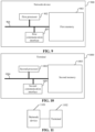
- the embodiments of the present disclosure further provide a network device, as shown in FIG. 9 , the network device 900 includes: a first communication interface 901 and a first processor 902.
- the first communication interface 901 is capable of performing information interaction with a terminal.
- the first processor 902 is connected with the first communication interface 901 to implement information exchange with the terminal, and is configured to execute the method provided by one or more technical solutions on the network device side when running a computer program.
- the computer program is stored in a first memory 903.
- the first communication interface 901 is configured to transmit first information to the terminal, the first information indicating a first RS and a second RS, the first RS being associated with a Doppler shift, Doppler spread, average delay, and delay spread, and the second RS being associated with one of the following:
- the first communication interface 901 is configured to transmit the first information to the terminal by one of the following ways:
- the first communication interface 901 is configured to receive an uplink signal transmitted by the terminal, a modulated carrier frequency of the uplink signal being associated with a carrier frequency at which the first RS is received, or the modulated carrier frequency of the uplink signal being unassociated with a carrier frequency at which the second RS is received.
- the first processor 902 is configured to: perform frequency shift estimation by using the received uplink signal and determine a Doppler shift compensation value of at least one TRP.
- the at least one TRP does not contain the TRP transmitting the first RS.
- bus system 904. is configured to implement connection communication between these components.
- the bus system 904 further includes a power bus, a control bus and a status signal bus.
- the various buses are marked as the bus system 904 in FIG. 9 .
- the first memory 903 in the embodiments of the present disclosure is configured to store various types of data to support the operation of the network device 900.
- Examples of the data include: any computer program configured to operate on the network device 900.
- the method disclosed in the above embodiments of the present disclosure may be applied to the first processor 902 or implemented by the first processor 902.
- the first processor 902 may be an integrated circuit chip with signal processing capabilities. In an implementation process, each step of the method may be completed by an integrated logical circuit of hardware in the first processor 902 or an instruction in a software form.
- the first processor 902 described above may be a general-purpose processor, a Digital Signal Processor (DSP), or other programmable logic devices, discrete gates or transistor logic devices, discrete hardware components, etc.
- DSP Digital Signal Processor
- Various methods, steps, and logic block diagrams disclosed in the embodiments of the present disclosure may be implemented or executed by the first processor 902.
- the general-purpose processor may be a microprocessor or any conventional processor, etc.
- the steps of the methods disclosed in combination with the embodiment of the present disclosure may be directly embodied as a hardware decoding processor for execution and completion, or a combination of hardware and software modules in the decoding processor for execution and completion.
- the software module may be located in a storage medium, which is located in the first memory 903, and the first processor 902 reads information in the first memory 903, and completes the steps of the foregoing method in combination with hardware.
- the network device 900 may be implemented by one or more Application Specific Integrated Circuits (ASICs), DSPs, Programmable Logic Devices (PLDs), Complex Programmable Logic Devices (CPLDs), FPGAs, general purpose processors, controllers, Micro Controller Units (MCUs), Microprocessors, or other electronic components, and is configured to execute the foregoing method.
- ASICs Application Specific Integrated Circuits
- DSPs Digital Signal processors
- PLDs Programmable Logic Devices
- CPLDs Complex Programmable Logic Devices
- FPGAs general purpose processors
- controllers controllers
- MCUs Micro Controller Units
- Microprocessors or other electronic components
- the terminal 1000 includes: a second communication interface 1001 and a second processor 1002.
- the second communication interface 1001 is capable of performing information interaction with the network device.
- the second processor 1002 is connected with the second communication interface 1001 to implement information exchange with the network device, and is configured to execute the method provided by one or more technical solutions on the terminal side when running a computer program.
- the computer program is stored in a second memory 1003.
- the second communication interface 1001 is configured to receive first information transmitted by a network side, the first information indicating a first RS and a second RS, the first RS being associated with a Doppler shift, Doppler spread, average delay, and delay spread, and the second RS being associated with one of the following:
- the second communication interface 1001 is configured to receive the first information transmitted by the network side by one of the following ways:
- the second RS may be associated with the Doppler shift, the Doppler spread, the average delay, and the delay spread.
- the second processor 1002 is configured to determine, based on the first information, that the second RS is associated with one of:
- the second processor 1002 is further configured to determine a modulated carrier frequency of an uplink signal, the modulated carrier frequency of the uplink signal being associated with a carrier frequency at which the first RS is received, or the modulated carrier frequency of the uplink signal is unassociated with a carrier frequency at which the second RS is received.
- the second communication interface 1001 is further configured to transmit the uplink signal at the determined modulated carrier frequency.
- the transmitted uplink signal may be configured to determine, by the network side, a Doppler shift compensation value of at least one TRP.
- the at least one TRP does not contain the TRP transmitting the first RS.
- bus system 1004. is configured to implement connection communication between these components.
- the bus system 1004 also includes a power bus, a control bus and a status signal bus.
- the various buses are marked as the bus system 1004 in FIG. 10 .
- the second memory 1003 in the embodiments of the present disclosure is configured to store various types of data to support the operation of the terminal 1000. Examples of these data include: any computer program configured to operate on the terminal 1000.
- the method disclosed in the above embodiments of the present disclosure may be applied to the second processor 1002 or implemented by the second processor 1002.
- the second processor 1002 may be an integrated circuit chip with signal processing capabilities. In an implementation process, each step of the method may be completed by an integrated logical circuit of hardware in the second processor 1002 or an instruction in a software form.
- the second processor 1002 described above may be a general-purpose processor, a DSP, or other programmable logic devices, discrete gates or transistor logic devices, discrete hardware components, etc.
- Various methods, steps, and logic block diagrams disclosed in the embodiments of the present disclosure may be implemented or executed by the second processor 1002.
- the general-purpose processor may be a microprocessor or any conventional processor, etc.
- the steps of the methods disclosed in combination with the embodiment of the present disclosure may be directly embodied as a hardware decoding processor for execution and completion, or a combination of hardware and software modules in the decoding processor for execution and completion.
- the software module may be located in a storage medium, which is located in the second memory 1003, and the second processor 1002 reads information in the second memory 1003, and completes the steps of the foregoing method in combination with hardware.
- the terminal 1000 may be implemented by one or more ASICs, DSPs, PLDs, CPLDs, FPGAs, general purpose processors, controllers, MCUs, Microprocessors, or other electronic components, and is configured to execute the foregoing method.
- the memories may be volatile memories or nonvolatile memories, and may also include both volatile and nonvolatile memories.
- the non-volatile memory may be a Read Only Memory (ROM), a Programmable ROM (PROM), an Erasable PROM (EPROM), an Electrically EPROM (EEPROM), a Ferromagnetic Random Access Memory (FRAM), a Flash Memory, a magnetic surface memory, an optical disk, or a Compact Disc-ROM (CD-ROM).
- the magnetic surface memory may be a magnetic disk memory or a magnetic tape memory.
- the volatile memory may be a Random Access Memory (RAM), which is used as an external cache.
- RAM Random Rambus RAM
- SRAM Static RAM
- SSRAM Synchronous SRAM
- DRAM Dynamic RAM
- SDRAM Synchronous DRAM
- DDRSDRAM Double Data Rate SDRAM
- ESDRAM Enhanced SDRAM
- SLDRAM Synchlink DRAM
- DRRAM Direct Rambus RAM
- the embodiments of the present invention further provide an information transmission system, as shown in FIG. 11 , which includes: a network device 1101 and a terminal 1102.
- the embodiments of the present disclosure also provide a storage medium, that is, a computer storage medium, specifically a computer readable storage medium, such as a first memory 903 including a stored computer program, which may be executed by the first processor 902 of the network device 900 to complete the steps of the foregoing method on the network device side.
- a storage medium such as a computer storage medium, specifically a computer readable storage medium, such as a first memory 903 including a stored computer program, which may be executed by the first processor 902 of the network device 900 to complete the steps of the foregoing method on the network device side.
- it may be a second memory 1003 including the stored computer program, which may be executed by the second processor 1002 of the terminal 1000 to complete the steps of the foregoing method on the terminal side.
- the computer readable storage medium may be the memory such as the FRAM, the ROM, the PROM, the EPROM, the EEPROM, the Flash Memory, the magnetic surface memory, the optical disk, or CD-ROM.
Landscapes
- Engineering & Computer Science (AREA)
- Signal Processing (AREA)
- Computer Networks & Wireless Communication (AREA)
- Mobile Radio Communication Systems (AREA)
- Transceivers (AREA)
- Signal Processing For Digital Recording And Reproducing (AREA)
Abstract
Description
- The present disclosure is based on and claims priority to
Chinese patent application No. 202010550868.4, filed on June, 16, 2020 - The present disclosure relates to the field of wireless communication, and in particular to an information transmission method and apparatus, a related device, and a storage medium.
- With the development of the communication technology, high mobility up to 500 km/h is expected to be enabled with an acceptable Quality of Service (QoS) in a communication system, which is envisioned in particular for High Speed Trains (HSTs). The HST scenario is also one of the important New Radio (NR) deployment scenarios in the 5th Generation Mobile Communication Technology (5G). The key characteristics of the HST scenario are consistent passenger user experience and critical train communication reliability with very high mobility.
- One of the most important HST scenarios is a Single Frequency Network (SFN) deployment scenario, that is, an HST-SFN deployment scenario. In the HST-SFN deployment scenario, as shown in
FIG. 1 , a plurality of Remote Radio Heads (RRHs) are connected to one Base Band Unit (BBU) through optical fibers, and share the same cell Identity (ID), so as to reduce the number of handovers and improve user experience as much as possible. For each RRH, there are usually two Transmission and Reception Points (TRPs) which orient opposite directions along the track. At least in a 5G commercial network, the HST-SFN deployment is still the most important solution for an NR HST. - In the HST-SFN deployment scenario, how to accurately perform channel estimation when a terminal receives signals transmitted by the plurality of TRPs is an urgent problem to be solved at present.
- In order to solve the relevant technical problems, embodiments of the present disclosure provide an information transmission method and apparatus, a related device, and a storage medium.
- The technical solutions of the embodiments of the present disclosure are implemented as follows.
- At least one embodiment of the present disclosure provides an information transmission method, which is applied to a network device and may include the following operation.
- First information is transmitted to a terminal. The first information indicates a first Reference Signal (RS) and a second RS, the first RS is associated with a Doppler shift, Doppler spread, average delay and delay spread, and the second RS is associated with one of the following:
- average delay;
- delay spread; and
- average delay and delay spread.
- In addition, according to at least one embodiment of the present disclosure, the first information is transmitted to the terminal by one of the following ways:
- Radio Resource Control (RRC) signaling;
- Medium Access Control Control Element (MAC CE); and
- Downlink Control Information (DCI).
- In addition, according to at least one embodiment of the present disclosure, the first RS may include a first Tracking Reference Signal (TRS); and the second RS may include a second TRS.
- In addition, according to at least one embodiment of the present disclosure, the method may further include the following operation.
- An uplink signal transmitted by the terminal is received. A modulated carrier frequency of the uplink signal is associated with a carrier frequency at which the first RS is received, or the modulated carrier frequency of the uplink signal is unassociated with a carrier frequency at which the second RS is received.
- At least one embodiment of the present disclosure further provides an information transmission method, which is applied to a terminal and may include the following operation.
- First information transmitted by a network side is received. The first information indicates a first RS and a second RS, the first RS is associated with a Doppler shift, Doppler spread, average delay, and delay spread, and the second RS is associated with one of the following:
- average delay;
- delay spread; and
- average delay and delay spread.
- In addition, according to at least one embodiment of the present disclosure, the first information transmitted by the network side is received by one of the following ways:
- RRC signaling;
- MAC CE; and
- DCI.
- In addition, according to at least one embodiment of the present disclosure, the second RS may be associated with the Doppler shift, the Doppler spread, the average delay, and the delay spread.
- Using the first information, it is determined that the second RS is associated with one of:
- average delay;
- delay spread; and
- average delay and delay spread.
- In addition, according to at least one embodiment of the present disclosure, the first RS may include a first TRS; and the second RS may include a second TRS.
- In addition, according to at least one embodiment of the present disclosure, the method may further include the following operations.
- A modulated carrier frequency of an uplink signal is determined. The modulated carrier frequency of the uplink signal is associated with a carrier frequency at which the first RS is received, or the modulated carrier frequency of the uplink signal determining that the modulated carrier frequency of the uplink signal is unassociated with a carrier frequency at which the second RS is received.
- The uplink signal is transmitted at the determined modulated carrier frequency.
- At least one embodiment of the present disclosure provides an information transmission apparatus, which may include: a first transmitting unit.
- The first transmitting unit may be configured to transmit first information to a terminal. The first information indicates a first RS and a second RS, the first RS is associated with a Doppler shift, Doppler spread, average delay and delay spread, and the second RS is associated with one of the following:
- average delay;
- delay spread; and
- average delay and delay spread.
- At least one embodiment of the present disclosure provides an information transmission apparatus, which may include a first receiving unit.
- The first receiving unit may be configured to receive first information transmitted by a network side. The first information indicates a first RS and a second RS, the first RS is associated with a Doppler shift, Doppler spread, average delay, and delay spread, and the second RS is associated with one of the following:
- average delay;
- delay spread; and
- average delay and delay spread.
- At least one embodiment of the present disclosure further provides a network device, which may include: a first communication interface and a first processor.
- The first communication interface may be configured to transmit first information to a terminal, the first information indicating a first RS and a second RS, the first RS is associated with a Doppler shift, Doppler spread, average delay, and delay spread, and the second RS is associated with one of the following:
- average delay;
- delay spread; and
- average delay and delay spread.
- At least one embodiment of the present disclosure further provides a terminal, which may include: a second communication interface and a second processor.
- The second communication interface may be configured to receive first information transmitted by a network side. The first information indicates a first RS and a second RS, the first RS is associated with a Doppler shift, Doppler spread, average delay, and delay spread, and the second RS is associated with one of the following:
- average delay;
- delay spread; and
- average delay and delay spread.
- At least one embodiment of the present disclosure further provides a network device, which may include: a first processor and a first memory configured to store a computer program runnable on the processor.
- Herein, the first processor may be configured to execute the steps of any method on the network device side when running the computer program.
- At least one embodiment of the present disclosure further provides a terminal, which may include: a second processor and a second memory configured to store a computer program runnable on the processor.
- Herein, the second processor may be configured to execute the steps of any method on the terminal side when running the computer program.
- At least one embodiment of the present disclosure further provides a storage medium on which a computer program is stored. The computer program, when executed by a processor, implements the steps of any method on the network device side, or implements the steps of any method on the terminal side.
- According to the information transmission method and apparatus, the related device, and the storage medium provided by the embodiments of the present disclosure, the network device transmits the first information to the terminal, the first information indicating the first RS and the second RS, the first RS being associated with the Doppler shift, the Doppler spread, the average delay and the delay spread, and the second RS being associated with one of the following: the average delay; the delay spread; and the average delay and delay spread. Therefore, in the HST-SFN scenario, when the terminal receives a plurality of downlink signals, delay-related parameters can be accurately estimated, to improve user experience.
-
-
FIG. 1 is a schematic diagram of an HST-SFN deployment scenario in the related art. -
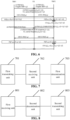
FIG. 2 is a flowchart of an information transmission method according to an embodiment of the present disclosure. -
FIG. 3 is a schematic diagram of an HST scenario according to an application embodiment of the present disclosure. -
FIG. 4 is a flowchart of performing Doppler shift pre-compensation according to an application embodiment of the present disclosure. -
FIG. 5 is a schematic diagram of an HST scenario according to an application embodiment of the present disclosure. -
FIG. 6 is another flowchart of performing Doppler shift pre-compensation according to an application embodiment of the present disclosure. -
FIG. 7 is a schematic structural diagram of an information transmission apparatus arranged on a network device according to an embodiment of the present disclosure. -
FIG. 8 is a schematic structural diagram of an information transmission apparatus arranged on a terminal according to an embodiment of the present disclosure. -
FIG. 9 is a schematic structural diagram of a network device according to an embodiment of the present disclosure. -
FIG. 10 is a schematic structural diagram of a terminal according to an embodiment of the present disclosure. -
FIG. 11 is a schematic structural diagram of an information transmission system according to an embodiment of the present disclosure. - The present disclosure is elaborated in detail below with reference to the drawings and embodiments.
- The important parameters used to characterize the HST-SFN deployment scenario is listed in Table 1.
Table 1 Parameter Value Carrier Frequency f C 2.6GHz RRH Railway track distance D min 150m Distance between two RRHs Ds 700m Cell Inter-Site Distance (ISD) 3.2km (4RRHs connect to 1 BBU) RRH height (compared to railway track) 25m - Herein, the values corresponding to the parameters are typical values used in commercial network deployment.
- In the HST-SFN deployment scenario, the greatest challenge comes from a high Doppler shift due to high speed (e.g., 500km/h), higher frequency (e.g., 2.6GHz, 3.5GHz) and the characteristics of SFN deployment. For example, the Doppler shift could reach up to 1.2KHz fort 2.6GHz and about 1.6Hz for 3.5GHz. In addition, when the train is in the middle of two RRHs, if at a frequency of 3.5GHz, users in the train will experience +1.6kHz and -1.6kHz Doppler shifts simultaneously. The significant difference of the two Doppler shifts experienced simultaneously by the User Equipment (UE) will result in great performance degradation. Similarly, the significant difference of two kinds of delay experienced simultaneously by the UE may also result in great performance degradation.
- Based on this, in various embodiments of the present disclosure, in the HST-SFN deployment scenario, an RS used by a terminal for delay estimation is indicated.
- The embodiments of the present disclosure provide an information transmission method, which is applied to a network device and includes the following operation.
- First information is transmitted to a terminal, the first information indicating a first Reference Signal (RS) and a second RS, the first RS being associated with a Doppler shift, Doppler spread, average delay and delay spread, and the second RS being associated with one of the following:
- average delay;
- delay spread;
- average delay and delay spread.
- Here, for the second RS, the first information actually indicates the second RS configured to determine at least one of the following parameters:
- average delay; and
- delay spread.
- In practical application, the network device may specifically be a base station.
- It is to be noted that, the solution of the embodiments of the present disclosure is applied to the HST-SFN deployment scenario, namely, a plurality of TRPs all transmit downlink signals (including the first RS and second RS), and at this time, the terminal may receive the plurality of downlink signals. When the plurality of TRPs transmit the RSs, the terminal can receive a plurality of Downlink Reference Signals (DL RSs).
- In the embodiments of the present disclosure, the network device itself may determine which RS may be applicable to the terminal, namely, the network device determines the first RS according to needs, and no limitations are made thereto in the embodiments of the present disclosure.
- In practical application, the first information may be transmitted to the terminal by one of the following ways:
- RRC signaling;
- MAC CE; and
- DCI.
- Herein, RRC signaling and the MAC CE may be referred to as high layer signaling, and the DCI is physical layer signaling.
- In practical application, the RRC signaling may be RRC reconfiguration signaling.
- In the related art, a plurality of Quasi Co-Location (QCL) types have been defined, and the role of a respective RS corresponding to each QCL type is also defined. The specific contents are as follows.
- QCL-TypeA: {Doppler shift, Doppler spread, average delay, delay spread}, namely, an RS corresponding to QCL-TypeA may be configured to estimate the Doppler shift, the Doppler spread, the average delay and the average spread. That is, the RS corresponding to the QCL-TypeA may be associated with the Doppler shift, the Doppler spread, the average delay and the delay spread.
- QCL-TypeB: {Doppler shift, Doppler spread}, namely, an RS corresponding to QCL-TypeB may be configured to estimate the Doppler shift and the Doppler spread. That is, the RS corresponding to the QCL-TypeB may be associated with the Doppler shift and the Doppler spread.
- QCL-TypeC: {Doppler shift, average delay}, namely, an RS corresponding to QCL-TypeC may be configured to estimate the Doppler shift and the average delay. That is, the RS corresponding to the QCL-TypeC may be associated with the Doppler shift and the average delay.
- QCL-TypeD: {Spatial Rx parameter}, namely, an RS corresponding to QCL-TypeD may be configured to estimate a spatial reception parameter. That is, the RS corresponding to the QCL-TypeD may be associated with the spatial reception parameter.
- In a general scenario, channel estimation may be performed through the above RS. However, in the HST-SFN deployment scenario, the channel may not be accurately estimated by the above parameters. Therefore, the QCL type may be defined, the newly defined QCL type corresponds to one DL RS, namely, the second RS, configured for delay-related estimation.
- Based on this, in an embodiment, the newly defined QCL type corresponds to the second RS.
- Exemplarily, 'QCL-TypeE': {average delay, delay spread} may be defined, or 'QCL-TypeE': {average delay} may be defined, or 'QCL-TypeE': {delay spread} may be defined.
- Herein, 'QCL-TypeE': {average delay, delay spread} represents that the second RS may be configured to estimate the average delay and the delay spread, namely, the second RS is associated with the average delay and the delay spread. 'QCL-TypeE': {average delay} represents that the corresponding RS may be configured to estimate the average delay, namely, the second RS is associated with the average delay. 'QCL-TypeE': {delay spread} represents that the corresponding RS may be configured to estimate the delay spread, namely, the second RS is associated with the delay spread.
- In practical application, a Transmission Configuration Indication-State (TCI-State) is configured to indicate the RS corresponding to at least one QCL type configured by the terminal, so that the newly defined QCL type may be indicated through the TCI-State.
- Exemplarily, the newly defined QCL type may be indicated to the terminal by the network device as qcl-Type3 in the TCI-State, and the content of the TCI-State is as follows:

- Herein, the QCL type corresponding to qcl-Type1 and qcl-Type2 may be understood according to the related art, which will not be elaborated herein.
- In practical application, the second RS may also be based on the existing QCL-TypeA, namely, the second RS may be associated with the Doppler shift, the Doppler spread, the average delay and the delay spread. The terminal may determine, based on the first information, that the second RS is associated with one of the following:
- average delay;
- delay spread; and
- average delay and delay spread.
- In practical application, there may be at least one RS corresponding to the QCL-TypeA configured by a network side, at this time, the terminal may determine that at least one of the at least one RS corresponding to the QCL-TypeA configured by the network side is the second RS according to the first information, namely, at least one of the at least one RS corresponding to the QCL-TypeA is associated with one of the following:
- average delay;
- delay spread; and
- average delay and delay spread.
- In practical application, the network device needs to configure at least one RS to the terminal for channel estimation, which is transmitted by the plurality of TRPs.
- In the embodiment of the present disclosure, the first RS includes a first TRS; and the second RS includes a second TRS.
- The second RS may include one or more RSs.
- In practical application, the terminal transmits an uplink signal (such as the RS) based on the indication of the network device, so that the network device may perform Doppler shift estimation.
- Based on this, in an embodiment, the method may further include the following operation.
- An uplink signal transmitted by the terminal is received. The modulated carrier frequency of the uplink signal (which may also be understood as the carrier frequency of the uplink signal) is determined by using the first RS, that is, the modulated carrier frequency of the uplink signal is associated with the carrier frequency at which the first RS is received; or the modulated carrier frequency of the uplink signal is unassociated with the carrier frequency at which the second RS is received.
- Here, the network device may perform frequency shift estimation by using the received uplink signal and determine a Doppler shift compensation value of at least one TRP.
- Specifically, the network device performs frequency shift estimation on the plurality of TRPs to obtain a frequency shift of the plurality of TRPs with respect to the carrier frequency of the first RS.
- A Doppler shift compensation value of at least one TRP is determined by using the obtained frequency shift of the plurality of TRPs with respect to the carrier frequency of the first RS. The at least one TRP does not contain the TRP transmitting the first RS.
- Herein, since the second RS is only configured to determine the average delay and/or delay spread and may not be configured to perform Doppler frequency related estimation, the terminal determines the carrier frequency of the uplink signal by using the first RS which may be configured to the estimate the Doppler frequency related estimation.
- In the embodiments of the present disclosure, the specific processing procedure of performing frequency shift estimation on the plurality of TRPs by using the received uplink signals is not limited. At the same time, a specific processing procedure of determining the Doppler shift compensation value of the at least one TRP by using the obtained frequency shift of the plurality of TRPs with respect to the carrier frequency of the first RS is also not limited.
- Since the RS for Doppler estimation is indicated to the terminal, when the terminal receives the plurality of downlink signals, the Doppler related parameters may be accurately estimated, so that the downlink Doppler pre-compensation in the HST-SFN scenario may be realized, thereby improving the user experience when receiving the plurality of downlink signals with a large difference in Doppler shift.
- Herein, in the embodiments of the present disclosure, the network device itself may determine which RS may be applicable to the terminal, namely, the network device determines the first RS and the second RS according to needs, and no limitations are made thereto in the embodiments of the present disclosure.
- In practical application, there may be one or more RSs associated with the uplink modulated carrier frequency of the terminal, that is, the first RS may include at least one RS. Accordingly, there may be one or more RSs unassociated with the uplink modulated carrier frequency of the terminal, that is, the second RS may include at least one RS.
- Accordingly, the embodiments of the present disclosure further provide an information transmission method, which is applied to a terminal and includes the following operation.
- First information transmitted by a network side is received, the first information indicating a first RS and a second RS, the first RS being associated with a Doppler shift, Doppler spread, average delay, and delay spread, and the second RS being associated with one of the following:
- average delay;
- delay spread; and
- average delay and delay spread.
- In an embodiment, the first information transmitted by the network side is received by one of the following ways:
- RRC signaling;
- MAC CE; and
- DCI.
- Specifically, when the network side transmits the first information through the RRC signaling, the terminal receives the first information through the RRC signaling. When the network side transmits the first information through the MAC CE, the terminal receives the first information through the MAC CE. When the network side transmits the first information through the DCI, the terminal receives the first information through the DCI.
- In practical application, the second RS may be based on the existing QCL-TypeA, namely, the second RS may be associated with the Doppler shift, the Doppler spread, the average delay and the delay spread. After receiving the first information, the terminal may determine, based on the first information, that the second RS is associated with one of the following:
- average delay;
- delay spread; and
- average delay and delay spread.
- Exemplarily, it is pre-defined that, as long as the terminal receives the first information, it can determine that the second RS is associated with one of the following:
- average delay;
- delay spread; and
- average delay and delay spread.
- For another example, the first information includes a specific ID. When indicating the second RS, as long as the specific ID is seen, it may be determined that the second RS is associated with one of the following:
- average delay;
- delay spread; and
- average delay and delay spread.
- In an embodiment, the method may further include the following operations.
- A modulated carrier frequency of an uplink signal (which may also be understood as an uplink modulated carrier frequency or an uplink carrier frequency) is determined.
- The uplink signal is transmitted at the determined modulated carrier frequency. The transmitted uplink signal may be configured to determine, by the network side, a Doppler shift compensation value of at least one TRP. The at least one TRP does not contain the TRP transmitting the first RS.
- Herein, in the embodiments of the present disclosure, the specific processing procedure of determining the modulated carrier frequency of the uplink RS by using the first RS is not limited.
- In practical application, the terminal may determine the modulated carrier frequency of the uplink signal at least based on the first RS (at least one other RS functionally similar to the first RS may be further used), so that the modulated carrier frequency of the uplink signal is associated with the carrier frequency at which the first RS is received, or the modulated carrier frequency of the uplink signal determines that the modulated carrier frequency of the uplink signal is unassociated with the carrier frequency at which the second RS is received.
- Herein, by using a predefined way, after receiving the first information, the terminal may determine that the modulated carrier frequency of the uplink signal is associated with the carrier frequency at which the first RS is received, or the modulated carrier frequency of the uplink signal determines that the modulated carrier frequency of the uplink signal is unassociated with the carrier frequency at which the second RS is received. The network device may also indicate that the modulated carrier frequency of the uplink signal is associated with the carrier frequency at which the first RS is received, or that the modulated carrier frequency of the uplink signal determines that the modulated carrier frequency of the uplink signal is unassociated with the carrier frequency at which the second RS is received.
- Here, in a case where the network device indicates that the modulated carrier frequency of the uplink signal of the terminal is associated with the carrier frequency at which the first RS is received, the indication is associated with the first RS. The network device indicates that the uplink modulated carrier frequency of the terminal is associated with the carrier frequency at which the first RS is received, which may also be understood as that the network device indicates, to the terminal, determining the carrier frequency of the uplink signal at least according to the carrier frequency at which the first RS is received, namely, indicating, to the terminal, determining the modulated carrier frequency of the uplink signal at least according to the reception of the first RS.
- When the network device indicates that the uplink modulated carrier frequency of the terminal is unassociated with the carrier frequency at which the second RS is received, the indication is associated with the second RS. The network device indicates that the uplink modulated carrier frequency of the terminal is unassociated with the carrier frequency at which the second RS is received, which may also be understood as that, the network device indicates, to the terminal, not determining the carrier frequency of the uplink signal according to the carrier frequency at which the second RS is received, namely, the network device indicates, to the terminal, not determining the carrier frequency of the uplink signal according to the reception of the second RS.
- In the embodiments of the present disclosure, the specific processing procedure of determining the modulated carrier frequency of the uplink RS is not limited.
- The embodiments of the present disclosure further provide an information transmission method, as shown in
FIG. 2 , which includes the following operations. - At S201, a network device transmits first information to a terminal, the first information indicating a first RS and a second RS, the first RS being associated with a Doppler shift, Doppler spread, average delay and delay spread, and the second RS being associated with one of the following:
- average delay;
- delay spread; and
- average delay and delay spread.
- At S202, the terminal receives the first information.
- It is to be noted that the specific processing processes of the network device and the terminal have been described in detail above, which will not be elaborated herein.
- According to the information transmission method provided by the embodiments of the present disclosure, the network device transmits the first information to the terminal, the first information indicating the first RS and the second RS, the first RS being associated with the Doppler shift, the Doppler spread, the average delay and the delay spread, and the second RS being associated with one of the following: the average delay; the delay spread; and the average delay and delay spread. Since the RS configured to perform delay estimation is indicated to the terminal, in the HST-SFN scenario, when the terminal receives a plurality of downlink signals, delay-related parameters can be accurately estimated. In this way, accurate estimation of downlink delay in the HST-SFN scenario can be realized, so as to improve the user experience when receiving the plurality of downlink signals with a large delay difference.
- The present disclosure is further described in detail below in combination with the application embodiments.
- In the application embodiment, as shown in
FIG. 3 , assuming that in an HST scenario, that is, in an HST-SFN scenario, TRP0, TRP1, TRP2 and TRP3 are four TRPs connected to the same cell, and assuming that an HST user is located at the position shown inFIG. 3 , at this time, since the antenna orientations of TRP0 and TRP3 may make the UE receive the signals transmitted by TRP0 and TRP3 weaker, the influence of the signals transmitted by TRP0 and TRP3 may be ignored. - Meanwhile, a base station transmits high layer signaling (such as RRC configuration signaling or MAC CE) or physical layer signaling (such as DCI) to the UE. The signaling is associated with TRSO (namely, a third RS), and the signaling indicates that the modulated carrier frequency of the UE is associated with the carrier frequency at which TRSO is received, or the signaling indicates that the UE determines the carrier frequency of the uplink signal according to the carrier frequency at which TRSO is received. Or, the signaling is associated with TRSSFN,i, (namely, a fourth RS, a TRS which may be transmitted by all TRPs connected to the same cell), and the signaling indicates that the modulated carrier frequency of the UE is unassociated with the carrier frequency at which TRSSFN,i is received, or the signaling indicates that the UE does not determine the carrier frequency of the uplink signal according to the carrier frequency at which TRSSFN,i is received.
- In the application embodiment, the base station configures periodic TRSO and TRSSFN,i, and the plurality of TRPs (such as TRP1 and TRP2) connected to the same cell for the UE, TRSO being transmitted by only a part of the TRP (it is assumed that TRSO is transmitted by TRP1, and TRP2 does not transmit TRSO), and TRSSFN,i being transmitted by the same TRP as the plurality of TRPs transmitting a Physical Downlink Shared Channel (PDSCH) and a Demodulation Reference Signal (DMRS) (it is assumed that TRSSFN,i, PDSCH and DMRS are all transmitted commonly by TRP1 and TRP2).
- A flow of performing, by a base station, Doppler shift pre-compensation is described below in combination with
FIG. 4 , and the flow includes the following operations. - At S1, TRP1 transmits TRSO at the carrier frequency fC.
- At S2, the UE receives TRSO, and determines the uplink modulated carrier frequency based on TRS0.
- Here, assuming that the Doppler shift is △f 1, the uplink modulated carrier frequency determined based on the reception of TRSO is fUE =f C+△f 1.
- At S3, the UE transmits the uplink RS, such as a Sounding Reference Signal (SRS), at the carrier frequency fUE.
- At S4, frequency shift (namely, frequency shift) estimation is performed based on the uplink RS.
- Here, assuming that TRP1 estimates the frequency shift with respect to fC to be 2△f 1 (the carrier frequency corresponding to TRP1 is f TRP1=fUE +△f 1=fC +△f 1+△f 1=fC +2△f 1), and TRP2 estimates the frequency shift with respect to fC to be △f 1+△f 2 (the carrier frequency corresponding to TRP2 is f TPR2=fUE +△f 2=f C+△f 1+△f 2). △f 2 is the Doppler shift corresponding to TRP2.
- At S5, the base station calculates a Doppler shift pre-compensation value used by the user for TRP2.
- Specifically, △f pre2=△f 1-△f 2.
- At S6, TRP1 transmits TRSSFN,i, DMRS and PDSCH at the carrier frequency fC. TRP2 transmits TRSSFN,i, DMRS and PDSCH at the carrier frequency fC +△ pre2 =fC +△f 1-△f 2. TRP1 transmits TRSO at the carrier frequency fC.
- At S7, the UE receives TRSO, TRSSFN,i, DMRS and PDSCH at the carrier frequency fC +△f 1, and determines the uplink carrier frequency as fUE =f C+△f 1 based on the reception of TRS0.
- Here, the UE determines the uplink modulated carrier frequency by using the carrier frequency fC, namely, the uplink modulated carrier frequency is fUE =f C+△f 1 .
- At S8, the UE transmits the uplink RS, such as SRS, at the carrier frequency fUE.
- At S9, frequency shift estimation is performed based on the uplink RS. Assuming that TRP1 estimates the frequency shift with respect to fC to be 2△f 1, TRP2 estimates the frequency shift with respect to fC to be △f 1+△f 2.
- At S10, the base station calculates a Doppler shift pre-compensation value used by the user for TRP2, specifically, △f pre2=△f 1-△f 2, and the subsequent steps are continuously executed.
- It is to be noted that, since the periodic TRS is transmitted periodically, the above process is performed periodically, and the order of some of the above steps is merely exemplary and not a strict sequence.
- In the application embodiment, a new QCL type is defined and corresponds to a DL RS, such as 'QCL-TypeE': {average delay, delay spread}, or 'QCL-TypeE': {average delay} is defined, or 'QCL-TypeE': {delay spread} is defined. The new QCL type may be indicated to UE by the network side as qcl-Type3 in a TCI-State.
- The base station transmits indication signaling to the UE through high layer signaling (such as RRC configuration or MAC CE) or physical layer signaling (such as DCI), the indication signaling being associated with a first TCI-State, and the first TCI-State indicating an RS corresponding to 'QCL-TypeA' and an RS corresponding to 'QCL-TypeE' of the UE. It is assumed that the RS corresponding to 'QCL-TypeA' is a first TRS (namely, a first RS), and it is assumed that the RS corresponding to 'QCL-TypeE' is a second TRS (namely, a second RS).
- Herein, for a DMRS of a PDSCH, the UE expects the TCI-State to indicate one of the following QCL types:
- 'QCL-TypeA' with a CSI-RS resource in a NZP-CSI-RS-ResourceSet configured with higher layer parameter trs-Info and, when applicable, 'QCL-TypeD' with the same CSI-RS resource;
- 'QCL-TypeA' with a CSI-RS resource in a NZP-CSI-RS-ResourceSet configured with higher layer parameter trs-Info and, when applicable, 'QCL-TypeD' with a CSI-RS resource in an NZP-CSI-RS-ResourceSet configured with higher layer parameter repetition;
- QCL-TypeA' with a CSI-RS resource in a NZP-CSI-RS-ResourceSet configured without higher layer parameter trs-Info and without higher layer parameter repetition and, when applicable, 'QCL-TypeD' with the same CSI-RS resource; and
- 'QCL-TypeA' with a CSI-RS resource in a NZP-CSI-RS-ResourceSet configured with higher layer parameter trs-Info and, when applicable, 'QCL-TypeE' with another CSI-RS resource in a NZP-CSI-RS-ResourceSet configured with higher layer parameter trs-Info.
- Specifically, in the application embodiment, as shown in
FIG. 5 , assuming that in an HST scenario, that is, in an HST-SFN scenario, TRP0, TRP1, TRP2 and TRP3 are four TRPs connected to the same cell, and it is assumed that an HST user is located at the position shown inFIG. 5 , at this time, since the antenna orientations of TRP0 and TRP3 may make the UE receive the signals transmitted by TRP0 and TRP3 weaker, the influence of the signals transmitted by TRP0 and TRP3 may be ignored. - Assuming that the first TRS is TRSO, and the second TRS is TRS1, the base station transmits first indication signaling (namely, first information) to the UE through high layer signaling or physical layer signaling, the first indication signaling indicating one TCI-State to the UE, and the TCI-State indicating an RS TRSO corresponding to 'QCL-TypeA' and an RS TRS1 corresponding to 'QCL-TypeE' to the UE. According to the indication, the UE estimates a Doppler shift, doppler spread, average delay and average spread by using TRSO, and the UE estimates the average delay and/or the delay spread by using only TRS1, that is, the UE estimates the Doppler shift and the Doppler spread by using TRSO, and the UE estimates the average delay and/or delay spread by using TRSO and TRS1 together.
- In the application embodiment, a processing flow indicating that the carrier frequency of the terminal is associated with the carrier frequency of which DL RS and/or is unassociated with the carrier frequency of which DL RS may also be used. In this case, the base station may also transmit second indication signaling to the UE through high layer signaling (such as RRC configuration or MAC CE) or physical layer signaling (such as DCI), the second indication signaling indicating that the modulated carrier frequency of the UE is associated with the carrier frequency at which TRSO is received, and the second signaling may also indicating that the UE determines the carrier frequency of the uplink signal based on the carrier frequency at which TRSO is received.
- In the application embodiment, the base station configures periodic TRSO and TRS1, and the plurality of TRPs (such as TRP1 and TRP2) connected to the same cell for the UE, TRSO and TRS1 being transmitted by only a part of the TRP (for example, TRSO is transmitted by TRP1, and TRP2 does not transmit TRS0; TRS1 is transmitted by TRP2, and TRP1 does not transmit TRS1), and a PDSCH and a DMRS are transmitted commonly by
TRS 1 and TRS2 (for example, the PDSCH and the DMRS are transmitted commonly by TRP1 and TRP2). - A flow of performing, by a base station, Doppler shift pre-compensation is described below in combination with
FIG. 6 , and the flow includes the following operations. - At S1, TRP1 transmits TRSO at the carrier frequency fC, TRP2 transmits TRS1 at the carrier frequency fC, the base station transmits second indication signaling to the UE through high layer signaling or physical layer signaling, and the second indication signaling indicates, to the UE, determining the carrier frequency of the uplink signal based on the carrier frequency of TRS0.
- At S2, the UE receives TRSO, and determines the uplink modulated carrier frequency based on TRS0.
- Here, assuming that the Doppler shift corresponding to TRP1 is △f 1, the uplink modulated carrier frequency determined based on the reception of TRSO is fUE =f C+△f 1 .
- At S3, the UE transmits the uplink RS, such as an SRS, at the carrier frequency fUE.
- At S4, frequency shift estimation is performed based on the uplink RS.
- Here, it is assumed that TRP1 estimates the frequency shift with respect to fC to be 2△f 1 (the carrier frequency corresponding to TRP1 is f TRP1=fUE +△f 1=fC +△f 1+△f 1=fC +2△f 1), and TRP2 estimates the frequency shift with respect to fC to be △f 1+△f 2 (the carrier frequency corresponding to TRP2 is fTRP2 =fUE +△f2 =fC +△f 1+△f 2). △f 2 is the Doppler shift corresponding to TRP2.
- At S5, the base station calculates a Doppler shift pre-compensation value used by the user for TRP2.
- Specifically, △f pre2=△f 1-△f 2.
- At S6, the base station transmits a DL scheduling DCI to the UE, the DCI indicating one TCI-State, and the TCI-State being an RS TRSO corresponding to the 'QCL-TypeA' and an RS TRS1 corresponding to the 'QCL-TypeE' indicated by the UE. TRP1 and TRP2 transmit the DMRS and the PDSCH scheduled by the DCI at the carrier frequencies fC and f C+△f pre2=f C+△f 1-△f 2 respectively, and TRP1 transmits TRSO at the carrier frequency fC. TRP2 transmits TRS1 at the carrier frequency fC.
- At S7, the UE receives TRSO, the DMRS and the PDSCH at the carrier frequency fC +△f 1 , and the UE determines the uplink carrier frequency as fUE =fC +△f 1 based on the reception of TRS0. TRS1 is configured for delay-related estimation in DMRS channel estimation.
- Here, the UE determines the uplink modulated carrier frequency by using the carrier frequency fC, namely, the uplink modulated carrier frequency is fUE =fC +△f 1 .
- At S8, the UE transmits the uplink RS, such as an SRS, at the carrier frequency fUE.
- At S9, frequency shift estimation is performed based on the uplink RS. Assuming that TRP1 estimates the frequency shift with respect to fC to be 2△f 1, TRP2 estimates the frequency shift with respect to fC to be △f 1+△f 2.
- At S10, the base station calculates a Doppler shift pre-compensation value used for TRP2.
- Specifically, △f pre2=△f 1-△f 2, and the subsequent steps are continuously executed.
- It is to be noted that, since the periodic TRS is transmitted periodically, the above process is performed periodically, and the order of some of the above steps is merely exemplary and not a strict sequence.
- The difference between the application embodiment and the
application embodiment 2 lies in that a base station transmits first indication signaling to UE through high layer signaling or physical layer signaling, the first indication signaling indicating one TCI-State to the UE, and the TCI-State indicating two RSs corresponding to 'QCL-TypeA' to the UE: TRS0 and TRS1. By means of pre-configuration or signaling indication, the UE is indicated that a certain RS (such as TRS1 in the embodiment) is only configured for estimation of average delay and/or delay spread. According to these indications, the UE estimates a Doppler shift, Doppler spread, average delay and average spread by using TRSO, and the UE estimates the average delay and/or the delay spread by using only TRS1, that is to say, the UE estimates the Doppler shift and the Doppler spread by using TRSO, and the UE estimates the average delay and/or the delay spread by using TRSO and TRS1 together. - The difference between the application embodiment and the
application embodiment 3 lies in that a base station transmits first indication signaling to UE through high layer signaling or physical layer signaling, the first indication signaling indicating two TCI-States to the UE, and each TCI-State indicating one RS, i.e., TRSO or TRS1, corresponding to 'QCL-TypeA' to the UE. By means of pre-configuration or signaling indication, the UE is indicated that a RS of 'QCL-TypeA' corresponding to a certain TCI State (such as TRS1 in the embodiment) is only configured for estimation of the average delay and/or delay spread. According to these indications, the UE estimates a Doppler shift, Doppler spread, average delay and average spread by using TRSO, and the UE estimates the average delay and/or the delay spread by using only TRS1, that is to say, the UE estimates the Doppler shift and the Doppler spread by using TRSO, and the UE estimates the average delay and/or the delay spread by using TRSO and TRS1 together. - In order to implement the method in the embodiments of the present disclosure, the embodiments of the present disclosure further provide an information transmission apparatus, which is arranged on a network device, as shown in
FIG. 7 , and includes afirst transmitting unit 701. - The
first transmitting unit 701 is configured to transmit first information to a terminal, the first information indicating a first RS and a second RS, the first RS being associated with a Doppler shift, Doppler spread, average delay and delay spread, and the second RS being associated with one of the following: - average delay;
- delay spread; and
- average delay and delay spread.
- In an embodiment, the
first transmitting unit 701 is configured to transmit the first information to the terminal by one of the following ways: - RRC signaling;
- MAC CE; and
- DCI.
- In an embodiment, as shown in
FIG. 7 , the apparatus may further include: asecond receiving unit 702. - The
second receiving unit 702 is configured to receive an uplink signal transmitted by the terminal, a modulated carrier frequency of the uplink signal being associated with a carrier frequency at which the first RS is received, or the modulated carrier frequency of the uplink signal determines that the modulated carrier frequency of the uplink signal being unassociated with a carrier frequency at which the second RS is received. - Herein, in an embodiment, as shown in
FIG. 7 , the apparatus may further include afirst determination unit 703. - The
first determination unit 703 is configured to:
perform frequency shift estimation by using the received uplink signal and determine a Doppler shift compensation value of at least one TRP. The at least one TRP does not contain a TRP transmitting the second RS. - In practical application, the
first transmitting unit 701 and thesecond receiving unit 702 may be implemented by a communication interface in the information transmission apparatus. Thefirst determination unit 703 may be implemented by a processor in the information transmission apparatus. - In order to implement the method on the terminal side in the embodiments of the present disclosure, the embodiments of the present disclosure further provide an information transmission apparatus, which is arranged on a terminal, as shown in
FIG. 8 , and includes afirst receiving unit 801. - The
first receiving unit 801 is configured to receive first information transmitted by a network side, the first information indicating a first RS and a second RS, the first RS being associated with a Doppler shift, Doppler spread, average delay, and delay spread, and the second RS being associated with one of the following: - average delay;
- delay spread; and
- average delay and delay spread.
- Herein, in an embodiment, the
first receiving unit 801 is configured to receive the first information transmitted by the network side by one of the following ways: - RRC signaling;
- MAC CE; and
- DCI.
- In an embodiment, the second RS may be associated with the Doppler shift, the Doppler spread, the average delay, and the delay spread, as shown in
FIG. 8 , the apparatus may further include asecond determination unit 802. - The
second determination unit 802 is configured to determine, based on the first information, that the second RS is associated with one of: - average delay;
- delay spread; and
- average delay and delay spread.
- In an embodiment, as shown in
FIG. 8 , the apparatus may further include asecond transmitting unit 802. - The
second determination unit 802 is further configured to determine a modulated carrier frequency of an uplink signal, the modulated carrier frequency of the uplink signal being associated with a carrier frequency at which the first RS is received, or the modulated carrier frequency of the uplink signal determining that the modulated carrier frequency of the uplink signal is unassociated with a carrier frequency at which the second RS is received. - The
second transmitting unit 803 is configured to transmit the uplink signal at the determined modulated carrier frequency. The transmitted uplink signal may be configured to determine, by the network side, a Doppler shift compensation value of at least one TRP. The at least one TRP does not contain the TRP transmitting the first RS. - In practical application, the
first receiving unit 801 and thesecond transmitting unit 803 may be implemented by a communication interface in the information transmission device. Thesecond determination unit 802 may be implemented by a processor in the information transmission apparatus. - It is to be noted that the information transmission apparatus provided by the above embodiments is only exemplified by the division of the above program modules when performing information transmission. In practical application, the above processing and allocation may be completed by different program modules as needed, that is, the internal structure of the apparatus is divided into different program modules to complete all or part of the above-described processing. In addition, the embodiments of the information transmission apparatus and the information transmission method provided by the embodiments belong to the same concept, and the detailed implementation processes thereof are detailed in the method embodiments and are not repeated here.
- Based on the hardware implementation of the above program modules, and in order to implement the method on the network device side of the embodiments of the present disclosure, the embodiments of the present disclosure further provide a network device, as shown in
FIG. 9 , thenetwork device 900 includes: afirst communication interface 901 and afirst processor 902. - The
first communication interface 901 is capable of performing information interaction with a terminal. - The
first processor 902 is connected with thefirst communication interface 901 to implement information exchange with the terminal, and is configured to execute the method provided by one or more technical solutions on the network device side when running a computer program. The computer program is stored in afirst memory 903. - Specifically, the
first communication interface 901 is configured to transmit first information to the terminal, the first information indicating a first RS and a second RS, the first RS being associated with a Doppler shift, Doppler spread, average delay, and delay spread, and the second RS being associated with one of the following: - average delay;
- delay spread; and
- average delay and delay spread.
- In an embodiment, the
first communication interface 901 is configured to transmit the first information to the terminal by one of the following ways: - RRC signaling;
- MAC CE; and
- DCI.
- In an embodiment, the
first communication interface 901 is configured to receive an uplink signal transmitted by the terminal, a modulated carrier frequency of the uplink signal being associated with a carrier frequency at which the first RS is received, or the modulated carrier frequency of the uplink signal being unassociated with a carrier frequency at which the second RS is received. - In an embodiment, the
first processor 902 is configured to:
perform frequency shift estimation by using the received uplink signal and determine a Doppler shift compensation value of at least one TRP. The at least one TRP does not contain the TRP transmitting the first RS. - It is to be noted that: the specific processing procedure of the
first communication interface 901 and thefirst processor 902 may be understood with reference to the methods described above. - Of course, in practical application, various components in the
network device 900 are coupled together through abus system 904. It is understandable that thebus system 904 is configured to implement connection communication between these components. In addition to the data bus, thebus system 904 further includes a power bus, a control bus and a status signal bus. However, for clarity of illustration, the various buses are marked as thebus system 904 inFIG. 9 . - The
first memory 903 in the embodiments of the present disclosure is configured to store various types of data to support the operation of thenetwork device 900. Examples of the data include: any computer program configured to operate on thenetwork device 900. - The method disclosed in the above embodiments of the present disclosure may be applied to the
first processor 902 or implemented by thefirst processor 902. Thefirst processor 902 may be an integrated circuit chip with signal processing capabilities. In an implementation process, each step of the method may be completed by an integrated logical circuit of hardware in thefirst processor 902 or an instruction in a software form. Thefirst processor 902 described above may be a general-purpose processor, a Digital Signal Processor (DSP), or other programmable logic devices, discrete gates or transistor logic devices, discrete hardware components, etc. Various methods, steps, and logic block diagrams disclosed in the embodiments of the present disclosure may be implemented or executed by thefirst processor 902. The general-purpose processor may be a microprocessor or any conventional processor, etc. The steps of the methods disclosed in combination with the embodiment of the present disclosure may be directly embodied as a hardware decoding processor for execution and completion, or a combination of hardware and software modules in the decoding processor for execution and completion. The software module may be located in a storage medium, which is located in thefirst memory 903, and thefirst processor 902 reads information in thefirst memory 903, and completes the steps of the foregoing method in combination with hardware. - In an exemplary embodiment, the
network device 900 may be implemented by one or more Application Specific Integrated Circuits (ASICs), DSPs, Programmable Logic Devices (PLDs), Complex Programmable Logic Devices (CPLDs), FPGAs, general purpose processors, controllers, Micro Controller Units (MCUs), Microprocessors, or other electronic components, and is configured to execute the foregoing method. - Based on the hardware implementation of the above program modules, and in order to implement the method on the terminal device side of the embodiments of the present disclosure, as shown in
FIG. 10 , the terminal 1000 includes: asecond communication interface 1001 and asecond processor 1002. - The
second communication interface 1001 is capable of performing information interaction with the network device. - The
second processor 1002 is connected with thesecond communication interface 1001 to implement information exchange with the network device, and is configured to execute the method provided by one or more technical solutions on the terminal side when running a computer program. The computer program is stored in asecond memory 1003. - Specifically, the
second communication interface 1001 is configured to receive first information transmitted by a network side, the first information indicating a first RS and a second RS, the first RS being associated with a Doppler shift, Doppler spread, average delay, and delay spread, and the second RS being associated with one of the following: - average delay;
- delay spread; and
- average delay and delay spread.
- Herein, in an embodiment, the
second communication interface 1001 is configured to receive the first information transmitted by the network side by one of the following ways: - RRC signaling;
- MAC CE; and
- DCI.
- In an embodiment, the second RS may be associated with the Doppler shift, the Doppler spread, the average delay, and the delay spread. The
second processor 1002 is configured to determine, based on the first information, that the second RS is associated with one of: - average delay;
- delay spread; and
- average delay and delay spread.
- In an embodiment, the
second processor 1002 is further configured to determine a modulated carrier frequency of an uplink signal, the modulated carrier frequency of the uplink signal being associated with a carrier frequency at which the first RS is received, or the modulated carrier frequency of the uplink signal is unassociated with a carrier frequency at which the second RS is received. - The
second communication interface 1001 is further configured to transmit the uplink signal at the determined modulated carrier frequency. The transmitted uplink signal may be configured to determine, by the network side, a Doppler shift compensation value of at least one TRP. The at least one TRP does not contain the TRP transmitting the first RS. - It is to be noted that: the specific processing procedure of the
second processor 1002 and thesecond communication interface 1001 may be understood with reference to the methods described above. - Of course, in practical application, various components in the terminal 1000 are coupled together through a
bus system 1004. It is understandable that thebus system 1004 is configured to implement connection communication between these components. In addition to the data bus, thebus system 1004 also includes a power bus, a control bus and a status signal bus. However, for clarity of illustration, the various buses are marked as thebus system 1004 inFIG. 10 . - The
second memory 1003 in the embodiments of the present disclosure is configured to store various types of data to support the operation of theterminal 1000. Examples of these data include: any computer program configured to operate on theterminal 1000. - The method disclosed in the above embodiments of the present disclosure may be applied to the
second processor 1002 or implemented by thesecond processor 1002. Thesecond processor 1002 may be an integrated circuit chip with signal processing capabilities. In an implementation process, each step of the method may be completed by an integrated logical circuit of hardware in thesecond processor 1002 or an instruction in a software form. Thesecond processor 1002 described above may be a general-purpose processor, a DSP, or other programmable logic devices, discrete gates or transistor logic devices, discrete hardware components, etc. Various methods, steps, and logic block diagrams disclosed in the embodiments of the present disclosure may be implemented or executed by thesecond processor 1002. The general-purpose processor may be a microprocessor or any conventional processor, etc. The steps of the methods disclosed in combination with the embodiment of the present disclosure may be directly embodied as a hardware decoding processor for execution and completion, or a combination of hardware and software modules in the decoding processor for execution and completion. The software module may be located in a storage medium, which is located in thesecond memory 1003, and thesecond processor 1002 reads information in thesecond memory 1003, and completes the steps of the foregoing method in combination with hardware. - In an exemplary embodiment, the terminal 1000 may be implemented by one or more ASICs, DSPs, PLDs, CPLDs, FPGAs, general purpose processors, controllers, MCUs, Microprocessors, or other electronic components, and is configured to execute the foregoing method.
- It is understandable that the memories (the
first memory 903 and the second memory 1003) in the embodiments of the present disclosure may be volatile memories or nonvolatile memories, and may also include both volatile and nonvolatile memories. Herein, the non-volatile memory may be a Read Only Memory (ROM), a Programmable ROM (PROM), an Erasable PROM (EPROM), an Electrically EPROM (EEPROM), a Ferromagnetic Random Access Memory (FRAM), a Flash Memory, a magnetic surface memory, an optical disk, or a Compact Disc-ROM (CD-ROM). The magnetic surface memory may be a magnetic disk memory or a magnetic tape memory. The volatile memory may be a Random Access Memory (RAM), which is used as an external cache. By way of example, but not limitation, many forms of RAM are available, such as a Static RAM (SRAM), a Synchronous SRAM (SSRAM), a Dynamic RAM (DRAM), a Synchronous DRAM (SDRAM), a Double Data Rate SDRAM (DDRSDRAM), an Enhanced SDRAM (ESDRAM), a Synchlink DRAM (SLDRAM), and a Direct Rambus RAM (DRRAM). The memories described in the embodiments of the present disclosure are intended to include, but not be limited to, these and any other suitable types of memories. - In order to implement the method of the embodiments of the present disclosure, the embodiments of the present invention further provide an information transmission system, as shown in
FIG. 11 , which includes: anetwork device 1101 and aterminal 1102. - It is to be noted that: the specific processing procedure of the
network device 1101 and the terminal 1102 have been described in detail above, and will not be elaborated herein. - In the exemplary embodiment, the embodiments of the present disclosure also provide a storage medium, that is, a computer storage medium, specifically a computer readable storage medium, such as a
first memory 903 including a stored computer program, which may be executed by thefirst processor 902 of thenetwork device 900 to complete the steps of the foregoing method on the network device side. For another example, it may be asecond memory 1003 including the stored computer program, which may be executed by thesecond processor 1002 of the terminal 1000 to complete the steps of the foregoing method on the terminal side. The computer readable storage medium may be the memory such as the FRAM, the ROM, the PROM, the EPROM, the EEPROM, the Flash Memory, the magnetic surface memory, the optical disk, or CD-ROM. - It is to be noted that the terms "first", "second" and the like are used to distinguish similar objects, and are not necessarily used to describe a specific order or sequence.
- In addition, the technical solutions described in the embodiments of the present disclosure may be arbitrarily combined without conflict.
- The description above is only the preferred embodiment of the present disclosure and is not intended to limit the scope of protection of the present disclosure.
Claims (16)
- An information transmission method, applied to a network device and comprising:
transmitting first information to a terminal, wherein the first information indicates a first Reference Signal (RS) and a second RS, the first RS is associated with a Doppler shift, Doppler spread, average delay and delay spread, and the second RS is associated with one of the following:average delay;delay spread; andaverage delay and delay spread. - The method of claim 1, wherein the first information is transmitted to the terminal by one of the following ways:Radio Resource Control (RRC) signaling;Medium Access Control Control Element (MAC CE); andDownlink Control Information (DCI).
- The method of claim 1, wherein the first RS comprises a first Tracking Reference Signal (TRS); and the second RS comprises a second TRS.
- The method of any one of claims 1-3, further comprising:
receiving an uplink signal transmitted by the terminal, wherein a modulated carrier frequency of the uplink signal is associated with a carrier frequency at which the first RS is received; or the modulated carrier frequency of the uplink signal is unassociated with a carrier frequency at which the second RS is received. - An information transmission method, applied to a terminal and comprising:
receiving first information transmitted by a network side, wherein the first information indicates a first Reference Signal (RS) and a second RS, the first RS is associated with a Doppler shift, Doppler spread, average delay, and delay spread, and the second RS is associated with one of the following:average delay;delay spread; andaverage delay and delay spread. - The method of claim 5, wherein the first information transmitted by the terminal side is received by one of the following ways:Radio Resource Control (RRC) signaling;Medium Access Control Control Element (MAC CE); andDownlink Control Information (DCI).
- The method of claim 5, wherein the second RS is capable of associated with the Doppler shift, the Doppler spread, the average delay, and the delay spread;
determining, by using the first information, that the second RS is associated with one of:average delay;delay spread; andaverage delay and delay spread. - The method of claim 5, wherein the first RS comprises a first Tracking Reference Signal (TRS); and the second RS comprises a second TRS.
- The method of any one of claims 5-8, further comprising:determining a modulated carrier frequency of an uplink signal, wherein the modulated carrier frequency of the uplink signal is associated with a carrier frequency at which the first RS is received, or determining, by the modulated carrier frequency of the uplink signal, that the modulated carrier frequency of the uplink signal is unassociated with a carrier frequency at which the second RS is received; andtransmitting the uplink signal at the determined modulated carrier frequency.
- An information transmission apparatus, comprising:
a first transmitting unit, configured to transmit first information to a terminal, wherein the first information indicates a first Reference Signal (RS) and a second RS, the first RS is associated with a Doppler shift, Doppler spread, average delay and delay spread, and the second RS is associated with one of the following:average delay;delay spread; andaverage delay and delay spread. - An information transmission apparatus, comprising:
a first receiving unit, configured to receive first information transmitted by a network side, wherein the first information indicates a first Reference Signal (RS) and a second RS, the first RS is associated with a Doppler shift, Doppler spread, average delay, and delay spread, and the second RS is associated with one of the following:average delay;delay spread; andaverage delay and delay spread. - A network device, comprising: a first communication interface and a first processor; wherein,
the first communication interface is configured to transmit first information to a terminal, wherein the first information indicates a first Reference Signal (RS) and a second RS, the first RS is associated with a Doppler shift, Doppler spread, average delay, and delay spread, and the second RS is associated with one of the following:average delay;delay spread; andaverage delay and delay spread. - A terminal, comprising: a second communication interface and a second processor; wherein,
the second communication interface is configured to receive first information transmitted by a network side, wherein the first information indicates a first Reference Signal (RS) and a second RS, the first RS is associated with a Doppler shift, Doppler spread, average delay, and delay spread, and the second RS is associated with one of the following:average delay;delay spread; andaverage delay and delay spread. - A network device, comprising: a first processor and a first memory configured to store a computer program runnable on the processor,
wherein the first processor is configured to execute the steps of the method of any one of claims 1-4 when running the computer program. - A terminal, comprising: a second processor and a second memory configured to store a computer program runnable on the processor,
wherein the second processor is configured to execute the steps of the method of any one of claims 5-9 when running the computer program. - A storage medium on which a computer program is stored, the computer program, when executed by a processor, implementing the steps of the method of any one of claims 1-4, or implementing the steps of the method of any one of claims 5-9.
Applications Claiming Priority (2)
| Application Number | Priority Date | Filing Date | Title |
|---|---|---|---|
| CN202010550868.4A CN113811002B (en) | 2020-06-16 | 2020-06-16 | Information transmission method, device, related equipment and storage device |
| PCT/CN2021/100275 WO2021254365A1 (en) | 2020-06-16 | 2021-06-16 | Information transmission method, apparatus, related device and storage device |
Publications (3)
| Publication Number | Publication Date |
|---|---|
| EP4152863A1 true EP4152863A1 (en) | 2023-03-22 |
| EP4152863A4 EP4152863A4 (en) | 2023-11-29 |
| EP4152863B1 EP4152863B1 (en) | 2025-08-27 |
Family
ID=78943370
Family Applications (1)
| Application Number | Title | Priority Date | Filing Date |
|---|---|---|---|
| EP21825267.4A Active EP4152863B1 (en) | 2020-06-16 | 2021-06-16 | Information transmission method, apparatus, related device and storage device |
Country Status (9)
| Country | Link |
|---|---|
| US (1) | US11876578B2 (en) |
| EP (1) | EP4152863B1 (en) |
| JP (1) | JP7470217B2 (en) |
| CN (1) | CN113811002B (en) |
| AU (1) | AU2021290693B2 (en) |
| BR (1) | BR112022025420A2 (en) |
| CA (1) | CA3182300A1 (en) |
| MX (1) | MX2022016178A (en) |
| WO (1) | WO2021254365A1 (en) |
Families Citing this family (4)
| Publication number | Priority date | Publication date | Assignee | Title |
|---|---|---|---|---|
| WO2022073192A1 (en) * | 2020-10-09 | 2022-04-14 | Lenovo (Beijing) Limited | Doppler shift frequency determination and compensation |
| JP2025500656A (en) * | 2022-01-11 | 2025-01-09 | 北京小米移動軟件有限公司 | Information reporting method, information receiving method, apparatus, device and storage medium |
| CN116683955A (en) * | 2022-02-23 | 2023-09-01 | 维沃移动通信有限公司 | Channel information reporting method, device, network side equipment, terminal and medium |
| WO2024250204A1 (en) * | 2023-06-07 | 2024-12-12 | Huawei Technologies Co., Ltd. | Method, Apparatus and system based on TCI/QCL framework for NTN communications |
Family Cites Families (13)
| Publication number | Priority date | Publication date | Assignee | Title |
|---|---|---|---|---|
| CN104253771B (en) * | 2013-06-27 | 2017-12-08 | 富士通株式会社 | Multi-parameter joint estimation method and device |
| US9930515B2 (en) * | 2014-05-15 | 2018-03-27 | Lg Electronics Inc. | Method for detecting discovery signal in wireless communication system, and device for same |
| CN110891301B (en) * | 2018-09-10 | 2021-08-24 | 维沃移动通信有限公司 | A channel measurement method, terminal device and network side device |
| US10944659B2 (en) * | 2018-10-05 | 2021-03-09 | Qualcomm Incorporated | Delay spread and average delay quasi-collocation sources for positioning reference signals |
| US20200374079A1 (en) * | 2019-08-15 | 2020-11-26 | Andrey Chervyakov | Single tap and single frequency network (sfn) high-speed train (hst) technologies |
| CN111082909B (en) * | 2019-08-15 | 2024-06-07 | 中兴通讯股份有限公司 | Quasi co-location hypothesis determining method and device, storage medium and electronic device |
| US12273846B2 (en) * | 2019-10-23 | 2025-04-08 | Qualcomm Incorporated | Enhanced reporting of positioning-related states |
| US20210226751A1 (en) * | 2020-01-17 | 2021-07-22 | Qualcomm Incorporated | Serving cell with distinct pci index per rrh for dl tci state, spatial relation, and ul tci state |
| KR20220133217A (en) * | 2020-02-14 | 2022-10-04 | 퀄컴 인코포레이티드 | Design and considerations for demodulation reference signal and tracking reference signal quasi-co-location relationship |
| US11641301B2 (en) * | 2020-02-21 | 2023-05-02 | Qualcomm Incorporated | Methods and apparatus for TRP differentiation based on SSB grouping |
| CN113365349B (en) | 2020-03-05 | 2023-07-04 | 大唐移动通信设备有限公司 | Signal transmission method, terminal, network equipment and storage medium |
| US11716113B2 (en) * | 2020-04-10 | 2023-08-01 | Qualcomm Incorporated | Frequency pre-compensation for high-speed train single frequency networks |
| US11870721B2 (en) * | 2020-05-14 | 2024-01-09 | Qualcomm Incorporated | Enhanced tracking reference signal patterns |
-
2020
- 2020-06-16 CN CN202010550868.4A patent/CN113811002B/en active Active
-
2021
- 2021-06-16 CA CA3182300A patent/CA3182300A1/en active Pending
- 2021-06-16 WO PCT/CN2021/100275 patent/WO2021254365A1/en not_active Ceased
- 2021-06-16 JP JP2022577264A patent/JP7470217B2/en active Active
- 2021-06-16 MX MX2022016178A patent/MX2022016178A/en unknown
- 2021-06-16 AU AU2021290693A patent/AU2021290693B2/en active Active
- 2021-06-16 EP EP21825267.4A patent/EP4152863B1/en active Active
- 2021-06-16 US US18/001,470 patent/US11876578B2/en active Active
- 2021-06-16 BR BR112022025420A patent/BR112022025420A2/en unknown
Also Published As
| Publication number | Publication date |
|---|---|
| BR112022025420A2 (en) | 2023-01-24 |
| EP4152863A4 (en) | 2023-11-29 |
| EP4152863B1 (en) | 2025-08-27 |
| AU2021290693A1 (en) | 2023-02-02 |
| US11876578B2 (en) | 2024-01-16 |
| MX2022016178A (en) | 2023-02-13 |
| CN113811002B (en) | 2025-01-28 |
| WO2021254365A1 (en) | 2021-12-23 |
| US20230261697A1 (en) | 2023-08-17 |
| CN113811002A (en) | 2021-12-17 |
| AU2021290693B2 (en) | 2023-11-30 |
| CA3182300A1 (en) | 2021-12-23 |
| JP7470217B2 (en) | 2024-04-17 |
| JP2023530968A (en) | 2023-07-20 |
Similar Documents
| Publication | Publication Date | Title |
|---|---|---|
| EP4152863B1 (en) | Information transmission method, apparatus, related device and storage device | |
| CN110972156B (en) | Interference measurement method, device, chip and storage medium | |
| US20250318008A1 (en) | Cell activation method and apparatus | |
| CN116388945B (en) | Method and device for obtaining quasi-co-location information | |
| CN111464473B (en) | Method and device for configuring information | |
| CN116097115B (en) | Positioning reference signal design for low power consumption tracking | |
| US12256423B2 (en) | Electronic device and method for scheduling restriction | |
| US20230262824A1 (en) | Methods and apparatus to speed up direct acell activation | |
| CN119856555A (en) | Positioning enhancement method | |
| CN116584142B (en) | Uplink signal transmission method and device | |
| EP4181596A1 (en) | Communication method, apparatus, and system | |
| EP4586564A1 (en) | Information determination method/apparatus/device and storage medium | |
| HK40081155A (en) | Information transmission method, apparatus, related device and storage device | |
| HK40081155B (en) | Information transmission method, apparatus, related device and storage device | |
| WO2024031624A1 (en) | Methods for rtt based passive sidelink positioning | |
| EP4482071A1 (en) | Communication method and apparatus, device and readable storage medium | |
| US20250008542A1 (en) | Configuration for in-x subnetworks | |
| US20240196399A1 (en) | Monitoring method and terminal | |
| US20240405944A1 (en) | Method for configuring information and device | |
| CN118511450A (en) | Apparatus and method for inter-cell beam management | |
| CN110708700B (en) | Terminal coverage method, communication device and computer readable storage medium | |
| CN115514460A (en) | Positioning method, positioning device and related equipment | |
| CN114339996A (en) | Beam searching method and device | |
| WO2024031633A1 (en) | Methods for rtt based sidelink positioning | |
| CN120825747A (en) | Communication method and communication device |
Legal Events
| Date | Code | Title | Description |
|---|---|---|---|
| STAA | Information on the status of an ep patent application or granted ep patent |
Free format text: STATUS: THE INTERNATIONAL PUBLICATION HAS BEEN MADE |
|
| PUAI | Public reference made under article 153(3) epc to a published international application that has entered the european phase |
Free format text: ORIGINAL CODE: 0009012 |
|
| STAA | Information on the status of an ep patent application or granted ep patent |
Free format text: STATUS: REQUEST FOR EXAMINATION WAS MADE |
|
| 17P | Request for examination filed |
Effective date: 20221215 |
|
| AK | Designated contracting states |
Kind code of ref document: A1 Designated state(s): AL AT BE BG CH CY CZ DE DK EE ES FI FR GB GR HR HU IE IS IT LI LT LU LV MC MK MT NL NO PL PT RO RS SE SI SK SM TR |
|
| REG | Reference to a national code |
Ref country code: HK Ref legal event code: DE Ref document number: 40081155 Country of ref document: HK |
|
| DAV | Request for validation of the european patent (deleted) | ||
| DAX | Request for extension of the european patent (deleted) | ||
| A4 | Supplementary search report drawn up and despatched |
Effective date: 20231027 |
|
| RIC1 | Information provided on ipc code assigned before grant |
Ipc: H04W 72/04 20230101AFI20231023BHEP |
|
| STAA | Information on the status of an ep patent application or granted ep patent |
Free format text: STATUS: EXAMINATION IS IN PROGRESS |
|
| 17Q | First examination report despatched |
Effective date: 20240624 |
|
| GRAP | Despatch of communication of intention to grant a patent |
Free format text: ORIGINAL CODE: EPIDOSNIGR1 |
|
| STAA | Information on the status of an ep patent application or granted ep patent |
Free format text: STATUS: GRANT OF PATENT IS INTENDED |
|
| INTG | Intention to grant announced |
Effective date: 20250507 |
|
| GRAS | Grant fee paid |
Free format text: ORIGINAL CODE: EPIDOSNIGR3 |
|
| GRAA | (expected) grant |
Free format text: ORIGINAL CODE: 0009210 |
|
| STAA | Information on the status of an ep patent application or granted ep patent |
Free format text: STATUS: THE PATENT HAS BEEN GRANTED |
|
| AK | Designated contracting states |
Kind code of ref document: B1 Designated state(s): AL AT BE BG CH CY CZ DE DK EE ES FI FR GB GR HR HU IE IS IT LI LT LU LV MC MK MT NL NO PL PT RO RS SE SI SK SM TR |
|
| REG | Reference to a national code |
Ref country code: CH Ref legal event code: EP |
|
| REG | Reference to a national code |
Ref country code: DE Ref legal event code: R096 Ref document number: 602021037350 Country of ref document: DE |
|
| REG | Reference to a national code |
Ref country code: IE Ref legal event code: FG4D |
|
| REG | Reference to a national code |
Ref country code: NL Ref legal event code: MP Effective date: 20250827 |
|
| PG25 | Lapsed in a contracting state [announced via postgrant information from national office to epo] |
Ref country code: IS Free format text: LAPSE BECAUSE OF FAILURE TO SUBMIT A TRANSLATION OF THE DESCRIPTION OR TO PAY THE FEE WITHIN THE PRESCRIBED TIME-LIMIT Effective date: 20251227 |
|
| PG25 | Lapsed in a contracting state [announced via postgrant information from national office to epo] |
Ref country code: NO Free format text: LAPSE BECAUSE OF FAILURE TO SUBMIT A TRANSLATION OF THE DESCRIPTION OR TO PAY THE FEE WITHIN THE PRESCRIBED TIME-LIMIT Effective date: 20251127 |
|
| REG | Reference to a national code |
Ref country code: LT Ref legal event code: MG9D |
|
| PG25 | Lapsed in a contracting state [announced via postgrant information from national office to epo] |
Ref country code: PT Free format text: LAPSE BECAUSE OF FAILURE TO SUBMIT A TRANSLATION OF THE DESCRIPTION OR TO PAY THE FEE WITHIN THE PRESCRIBED TIME-LIMIT Effective date: 20251229 |
|
| PG25 | Lapsed in a contracting state [announced via postgrant information from national office to epo] |
Ref country code: FI Free format text: LAPSE BECAUSE OF FAILURE TO SUBMIT A TRANSLATION OF THE DESCRIPTION OR TO PAY THE FEE WITHIN THE PRESCRIBED TIME-LIMIT Effective date: 20250827 |
|
| PG25 | Lapsed in a contracting state [announced via postgrant information from national office to epo] |
Ref country code: HR Free format text: LAPSE BECAUSE OF FAILURE TO SUBMIT A TRANSLATION OF THE DESCRIPTION OR TO PAY THE FEE WITHIN THE PRESCRIBED TIME-LIMIT Effective date: 20250827 Ref country code: NL Free format text: LAPSE BECAUSE OF FAILURE TO SUBMIT A TRANSLATION OF THE DESCRIPTION OR TO PAY THE FEE WITHIN THE PRESCRIBED TIME-LIMIT Effective date: 20250827 |
|
| PG25 | Lapsed in a contracting state [announced via postgrant information from national office to epo] |
Ref country code: GR Free format text: LAPSE BECAUSE OF FAILURE TO SUBMIT A TRANSLATION OF THE DESCRIPTION OR TO PAY THE FEE WITHIN THE PRESCRIBED TIME-LIMIT Effective date: 20251128 |
|
| PG25 | Lapsed in a contracting state [announced via postgrant information from national office to epo] |
Ref country code: SE Free format text: LAPSE BECAUSE OF FAILURE TO SUBMIT A TRANSLATION OF THE DESCRIPTION OR TO PAY THE FEE WITHIN THE PRESCRIBED TIME-LIMIT Effective date: 20250827 |
|
| PG25 | Lapsed in a contracting state [announced via postgrant information from national office to epo] |
Ref country code: LV Free format text: LAPSE BECAUSE OF FAILURE TO SUBMIT A TRANSLATION OF THE DESCRIPTION OR TO PAY THE FEE WITHIN THE PRESCRIBED TIME-LIMIT Effective date: 20250827 |
|
| PG25 | Lapsed in a contracting state [announced via postgrant information from national office to epo] |
Ref country code: PL Free format text: LAPSE BECAUSE OF FAILURE TO SUBMIT A TRANSLATION OF THE DESCRIPTION OR TO PAY THE FEE WITHIN THE PRESCRIBED TIME-LIMIT Effective date: 20250827 Ref country code: BG Free format text: LAPSE BECAUSE OF FAILURE TO SUBMIT A TRANSLATION OF THE DESCRIPTION OR TO PAY THE FEE WITHIN THE PRESCRIBED TIME-LIMIT Effective date: 20250827 |
|
| PG25 | Lapsed in a contracting state [announced via postgrant information from national office to epo] |
Ref country code: RS Free format text: LAPSE BECAUSE OF FAILURE TO SUBMIT A TRANSLATION OF THE DESCRIPTION OR TO PAY THE FEE WITHIN THE PRESCRIBED TIME-LIMIT Effective date: 20251127 |
|
| PG25 | Lapsed in a contracting state [announced via postgrant information from national office to epo] |
Ref country code: ES Free format text: LAPSE BECAUSE OF FAILURE TO SUBMIT A TRANSLATION OF THE DESCRIPTION OR TO PAY THE FEE WITHIN THE PRESCRIBED TIME-LIMIT Effective date: 20250827 |
|
| REG | Reference to a national code |
Ref country code: AT Ref legal event code: MK05 Ref document number: 1831630 Country of ref document: AT Kind code of ref document: T Effective date: 20250827 |
|
| PG25 | Lapsed in a contracting state [announced via postgrant information from national office to epo] |
Ref country code: SM Free format text: LAPSE BECAUSE OF FAILURE TO SUBMIT A TRANSLATION OF THE DESCRIPTION OR TO PAY THE FEE WITHIN THE PRESCRIBED TIME-LIMIT Effective date: 20250827 |
|
| PG25 | Lapsed in a contracting state [announced via postgrant information from national office to epo] |
Ref country code: DK Free format text: LAPSE BECAUSE OF FAILURE TO SUBMIT A TRANSLATION OF THE DESCRIPTION OR TO PAY THE FEE WITHIN THE PRESCRIBED TIME-LIMIT Effective date: 20250827 |
|
| PG25 | Lapsed in a contracting state [announced via postgrant information from national office to epo] |
Ref country code: AT Free format text: LAPSE BECAUSE OF FAILURE TO SUBMIT A TRANSLATION OF THE DESCRIPTION OR TO PAY THE FEE WITHIN THE PRESCRIBED TIME-LIMIT Effective date: 20250827 |
|
| PG25 | Lapsed in a contracting state [announced via postgrant information from national office to epo] |
Ref country code: IT Free format text: LAPSE BECAUSE OF FAILURE TO SUBMIT A TRANSLATION OF THE DESCRIPTION OR TO PAY THE FEE WITHIN THE PRESCRIBED TIME-LIMIT Effective date: 20250827 |
|
| PG25 | Lapsed in a contracting state [announced via postgrant information from national office to epo] |
Ref country code: CZ Free format text: LAPSE BECAUSE OF FAILURE TO SUBMIT A TRANSLATION OF THE DESCRIPTION OR TO PAY THE FEE WITHIN THE PRESCRIBED TIME-LIMIT Effective date: 20250827 |
|
| PG25 | Lapsed in a contracting state [announced via postgrant information from national office to epo] |
Ref country code: EE Free format text: LAPSE BECAUSE OF FAILURE TO SUBMIT A TRANSLATION OF THE DESCRIPTION OR TO PAY THE FEE WITHIN THE PRESCRIBED TIME-LIMIT Effective date: 20250827 Ref country code: SK Free format text: LAPSE BECAUSE OF FAILURE TO SUBMIT A TRANSLATION OF THE DESCRIPTION OR TO PAY THE FEE WITHIN THE PRESCRIBED TIME-LIMIT Effective date: 20250827 |