EP4152857A1 - Method and apparatus for acquiring uplink channel state information - Google Patents
Method and apparatus for acquiring uplink channel state information Download PDFInfo
- Publication number
- EP4152857A1 EP4152857A1 EP21804785.0A EP21804785A EP4152857A1 EP 4152857 A1 EP4152857 A1 EP 4152857A1 EP 21804785 A EP21804785 A EP 21804785A EP 4152857 A1 EP4152857 A1 EP 4152857A1
- Authority
- EP
- European Patent Office
- Prior art keywords
- uplink channel
- information
- srs
- terminal
- network side
- Prior art date
- Legal status (The legal status is an assumption and is not a legal conclusion. Google has not performed a legal analysis and makes no representation as to the accuracy of the status listed.)
- Granted
Links
Images


Classifications
-
- H—ELECTRICITY
- H04—ELECTRIC COMMUNICATION TECHNIQUE
- H04W—WIRELESS COMMUNICATION NETWORKS
- H04W72/00—Local resource management
- H04W72/20—Control channels or signalling for resource management
- H04W72/23—Control channels or signalling for resource management in the downlink direction of a wireless link, i.e. towards a terminal
-
- H—ELECTRICITY
- H04—ELECTRIC COMMUNICATION TECHNIQUE
- H04B—TRANSMISSION
- H04B1/00—Details of transmission systems, not covered by a single one of groups H04B3/00 - H04B13/00; Details of transmission systems not characterised by the medium used for transmission
- H04B1/69—Spread spectrum techniques
- H04B1/713—Spread spectrum techniques using frequency hopping
-
- H—ELECTRICITY
- H04—ELECTRIC COMMUNICATION TECHNIQUE
- H04B—TRANSMISSION
- H04B17/00—Monitoring; Testing
- H04B17/30—Monitoring; Testing of propagation channels
- H04B17/309—Measuring or estimating channel quality parameters
-
- H—ELECTRICITY
- H04—ELECTRIC COMMUNICATION TECHNIQUE
- H04B—TRANSMISSION
- H04B17/00—Monitoring; Testing
- H04B17/30—Monitoring; Testing of propagation channels
- H04B17/309—Measuring or estimating channel quality parameters
- H04B17/364—Delay profiles
-
- H—ELECTRICITY
- H04—ELECTRIC COMMUNICATION TECHNIQUE
- H04B—TRANSMISSION
- H04B17/00—Monitoring; Testing
- H04B17/30—Monitoring; Testing of propagation channels
- H04B17/382—Monitoring; Testing of propagation channels for resource allocation, admission control or handover
-
- H—ELECTRICITY
- H04—ELECTRIC COMMUNICATION TECHNIQUE
- H04L—TRANSMISSION OF DIGITAL INFORMATION, e.g. TELEGRAPHIC COMMUNICATION
- H04L5/00—Arrangements affording multiple use of the transmission path
- H04L5/003—Arrangements for allocating sub-channels of the transmission path
- H04L5/0048—Allocation of pilot signals, i.e. of signals known to the receiver
-
- H—ELECTRICITY
- H04—ELECTRIC COMMUNICATION TECHNIQUE
- H04L—TRANSMISSION OF DIGITAL INFORMATION, e.g. TELEGRAPHIC COMMUNICATION
- H04L5/00—Arrangements affording multiple use of the transmission path
- H04L5/003—Arrangements for allocating sub-channels of the transmission path
- H04L5/0048—Allocation of pilot signals, i.e. of signals known to the receiver
- H04L5/0051—Allocation of pilot signals, i.e. of signals known to the receiver of dedicated pilots, i.e. pilots destined for a single user or terminal
-
- H—ELECTRICITY
- H04—ELECTRIC COMMUNICATION TECHNIQUE
- H04L—TRANSMISSION OF DIGITAL INFORMATION, e.g. TELEGRAPHIC COMMUNICATION
- H04L5/00—Arrangements affording multiple use of the transmission path
- H04L5/003—Arrangements for allocating sub-channels of the transmission path
- H04L5/0058—Allocation criteria
- H04L5/0064—Rate requirement of the data, e.g. scalable bandwidth, data priority
-
- H—ELECTRICITY
- H04—ELECTRIC COMMUNICATION TECHNIQUE
- H04W—WIRELESS COMMUNICATION NETWORKS
- H04W72/00—Local resource management
- H04W72/04—Wireless resource allocation
- H04W72/044—Wireless resource allocation based on the type of the allocated resource
- H04W72/0453—Resources in frequency domain, e.g. a carrier in FDMA
-
- H—ELECTRICITY
- H04—ELECTRIC COMMUNICATION TECHNIQUE
- H04W—WIRELESS COMMUNICATION NETWORKS
- H04W72/00—Local resource management
- H04W72/50—Allocation or scheduling criteria for wireless resources
- H04W72/54—Allocation or scheduling criteria for wireless resources based on quality criteria
- H04W72/542—Allocation or scheduling criteria for wireless resources based on quality criteria using measured or perceived quality
Definitions
- the disclosure relates to the field of communication technologies, and in particular, to a method and apparatus for obtaining uplink channel state information.
- the reciprocity of the angle information and delay information of an uplink channel and a downlink channel is used, that is, the angle information of the uplink channel may be used as the angle information of the downlink channel, and the delay information of the uplink channel may be used as the delay information of the downlink channel.
- the port selection codebook and the enhanced port selection codebook are respectively defined, so as to assist the network side device to select an appropriate precoding matrix.
- the network side device configures corresponding Sounding Reference Signal (SRS) resources for the terminal, and the terminal sends an SRS to the network side device based on the SRS resource configuration, so that the network side device can determine the uplink channel information through the SRS sent by the terminal, and then obtain the angle information and delay information according to uplink channel information, where the angle information is used to characterize the sending angle of the signal, and the delay information is used to characterize the time required by the signal from the sender to the receiver.
- SRS Sounding Reference Signal
- the SRS resources configured for the terminal on the network side are as follows.
- one SRS resource may be sent on N consecutive Orthogonal Frequency Division Multiplexing (OFDM) symbols, where the value of N is 1, 2 or 4.
- OFDM Orthogonal Frequency Division Multiplexing
- one SRS resource has a comb-like (Comb) structure, that is, one SRS resource is not mapped on consecutive subcarriers.
- the Comb structure can be represented by the Comb parameter of which the value is 2 or 4, where the value of the Comb parameter being 2 indicates that one SRS resource is mapped at a spacing of one subcarrier, as shown by the SRS resource A and SRS resource B in FIG. 1 , and the value of the Comb parameter being 4 indicates that one SRS resource is mapped at a spacing of three subcarriers, as shown by the SRS resource C in FIG. 1 .
- ⁇ U represents the frequency interval of the uplink channel (that is, the interval of subcarriers, Physical Resource Blocks (PRBs) or uplink sub-bands)
- ⁇ m represents the delay of the m th transmission path
- N 3 U represents the number of Resource Elements (REs) occupied by the SRS sent on a sub-band or PRB of the uplink channel
- j represents an imaginary number.
- DFT Discrete Fourier Transform
- the delay information of the transmission path is related to ⁇ U and N 3 U .
- the network side device can capture the transmission path with a smaller delay.
- the network side device uses the existing SRS resource configuration method to configure the SRS resources for the terminal, the frequency interval of the Comb structure is small, that is, ⁇ U is small, so the transmission path with the smaller delay cannot be captured, and thus the more accurate channel delay information cannot be obtained.
- the terminal In order to capture the transmission path with the smaller delay, the terminal needs to send the SRS on a larger bandwidth, that is, the value of N 3 U is increased, so that the terminal needs to send the SRS on more frequency domain resources.
- the terminal due to the power limitation of the terminal, it is impossible for the terminal to simultaneously send the SRS on more subcarriers, PRBs or sub-bands when performing the uplink transmission.
- the disclosure provides a method and apparatus for obtaining uplink channel state information, so as to capture transmission paths with different delays, thereby designing a port selection codebook with higher precision.
- a method for obtaining uplink channel state information includes:
- the uplink channel state information includes angle information and/or delay information, where the angle information is used to characterize a signal emission angle and a signal arrival angle, and the delay information is used to characterize the time required for a signal to be sent from the terminal to the network side device.
- the preset bandwidth parameter is determined according to a maximum allowed uplink scheduled Bandwidth Part (BWP) or a maximum allowed downlink scheduled BWP
- the preset frequency domain density parameter is determined according to a frequency domain density of a downlink Channel State Information-Reference Signal (CSI-RS) or a sub-band size of a Precoding Matrix Indicator (PMI), where a value of the preset bandwidth parameter is an integer multiple of 4, and the preset bandwidth parameter is not greater than a maximum value of the downlink scheduled BWP in a case that the value of the preset bandwidth parameter is determined according to the downlink scheduled BWP.
- BWP Bandwidth Part
- PMI Precoding Matrix Indicator
- the determining, by the network side device, the SRS resource configuration information based on the preset bandwidth parameter, the preset frequency domain density parameter and the preset time domain parameter specifically includes:
- the measuring, by the network side device, the uplink channel used by the terminal based on the at least one SRS, and determining the corresponding uplink channel state information specifically includes:
- the measuring, by the network side device, the uplink channel used by the terminal based on the at least one SRS, and determining the corresponding uplink channel state information specifically includes:
- an apparatus for obtaining uplink channel state information includes:
- the uplink channel state information includes angle information and/or delay information, where the angle information is used to characterize a signal emission angle and a signal arrival angle, and the delay information is used to characterize the time required for a signal to be sent from the terminal to the network side device.
- the preset bandwidth parameter is determined according to a maximum allowed uplink scheduled BWP or a maximum allowed downlink scheduled BWP
- the preset frequency domain density parameter is determined according to a frequency domain density of a downlink CSI-RS or a sub-band size of a PMI, wherein a value of the preset bandwidth parameter is an integer multiple of 4, and the preset bandwidth parameter is not greater than a maximum value of the downlink scheduled BWP, in a case that the value of the preset bandwidth parameter is determined according to the downlink scheduled BWP.
- the processor when in a case that the SRS resource configuration information is determined based on the preset bandwidth parameter, the preset frequency domain density parameter and the preset time domain parameter, the processor is specifically configured to:
- the processor is specifically configured to:
- the processor is specifically configured to:
- an apparatus for obtaining uplink channel state information includes:
- a storage medium where instructions in the storage medium, when executed by a processor, enable the processor to perform the method for obtaining uplink channel state information as described in any one of the above embodiments.
- the network side device generates the SRS resource configuration information based on the preset bandwidth parameter, the preset frequency domain density parameter and the preset time domain parameter, and then the network side device measures the uplink channel used by the terminal based on at least one SRS returned by the terminal, and determines the corresponding uplink channel state information.
- the SRS resource configuration information is generated through the frequency domain density parameter.
- the frequency domain density of the SRS resource can be adjusted, that is, the frequency domain density of the SRS resource can be reduced. Since the frequency domain density is reduced, the signal to interference plus noise ratio of each SRS RE can be improved compared with the existing SRS resource allocation method, thereby increasing the coverage of the SRS.
- the bandwidth of SRS resource configuration is increased through the bandwidth parameter, so that the network side device can capture the transmission paths with different delays, thereby designing a port selection codebook with higher precision.
- the network side device configures at least one SRS resource for the terminal based on a preset bandwidth parameter, a preset frequency domain density parameter and a preset time domain parameters, and then measures an uplink channel based on at least one SRS to determine the uplink channel state information when receiving at least one SRS transmitted by the terminal using the at least one SRS resource.
- a process of obtaining the uplink channel state information in an embodiment of the disclosure is as follows.
- S201 a network side device determines the SRS resource configuration information based on a preset bandwidth parameter, a preset frequency domain density parameter and a preset time domain parameter when determining to obtain the uplink channel state information.
- the uplink channel state information includes any one or a combination of angle information or delay information, where the angle information is used to characterize a signal emission angle and a signal arrival angle, and the delay information is used to characterize the time required for a signal to be sent from the terminal to the network side device.
- the network side device includes but is not limited to a base station, a micro cell, etc.
- a base station a micro cell, etc.
- only the base station is taken as an example for description.
- the network side device determines to obtain the uplink channel state information when there are but not limited to the following cases.
- Case 1 the network side device determines to obtain the uplink channel state information when determining to schedule the uplink data transmission of the terminal based on a service request sent by the terminal.
- the base station determines to obtain the angle information and delay information when determining to schedule the uplink data transmission of the terminal based on a service request sent by the terminal.
- Case 2 the network side device determines to obtain the uplink channel state information when determining the precoding matrix for the downlink data transmission based on a service request sent by the terminal.
- the base station determines to obtain the angle information and delay information when determining the precoding matrix for the downlink data transmission based on a service request sent by the terminal.
- the network side device may configure the SRS resources by using, but not limited to, the following steps.
- the network side device determines a bandwidth configuration of at least one SRS resource based on the preset bandwidth parameter.
- the preset bandwidth parameter may be determined according to the maximum allowable uplink scheduled Bandwidth Part (BWP) or may be determined according to the downlink scheduled BWP, where the value of the preset bandwidth parameter is an integer multiple of 4, and the preset bandwidth parameter is not greater than the maximum value of the downlink scheduled BWP when the preset bandwidth parameter is determined according to the downlink scheduled BWP.
- BWP Bandwidth Part
- the preset bandwidth parameter is determined according to the maximum allowed uplink scheduled BWP, which is 256 PRBs.
- the preset bandwidth parameter is determined according to the downlink scheduled BWP, which is 256 PRBs.
- the network side device determines the frequency domain density of at least one SRS resource based on the preset frequency domain density parameter.
- the preset frequency domain density parameter may be determined according to the frequency domain density of a downlink Channel State Information-Reference Signal (CSI-RS), or may be determined according to the sub-band size of a Precoding Matrix Indicator (PMI).
- CSI-RS Downlink Channel State Information-Reference Signal
- PMI Precoding Matrix Indicator
- the network side device determines the frequency domain density k of at least one SRS resource as R / N PRB SB based on the preset frequency domain density parameter, where R represents the number of PMIs corresponding to a CQI sub-band during downlink data transmission, and N PRB SB represents the number of PRBs included in a CQI sub-band.
- the preset frequency domain density parameter is determined according to the frequency domain density of the CSI-RS, which is 0.25RE/Resource Block (RB)/PORT.
- the base station determines the frequency domain density of the SRS resource 1 as 0.25RE/RB/PORT based on the frequency domain density of the CSI-RS.
- the preset frequency domain density parameter is determined according to the sub-band size of the PMI, where the sub-band size N PRB SB of the CQI is 4 PRBs, and the value of R is 1.
- the sub-band size N PRB SB / R of the PMI is 4.
- the base station determines the frequency domain density k of the SRS resource 2 as 0.25 RE/RB/PORT based on the sub-band sizes of the CQI and the PMI.
- the network side device determines a time domain parameter N corresponding to at least one SRS resource based on the type of a service request or the uplink channel quality information of a known terminal.
- the terminal when the value of N is greater than 1, the terminal is instructed to send the at least one SRS in the frequency hopping manner on N OFDM symbols within one slot or across different slots; when the value of N is equal to 1, the terminal is instructed to send the at least one SRS in the frequency hopping manner across different slots.
- the base station determines the value of the time domain parameter N of the SRS resource 1 as 1 based on the type of the service request.
- the schematic diagram of the frequency domain density of the SRS resource 1 is shown in FIG. 3 , when the value of N is 1, the terminal is instructed to send the SRS 1 in the frequency hopping manner across different slots.
- the base station determines the value of the time domain parameter N of the SRS resource 2 as 4 based on the uplink channel quality information of the known terminal.
- the schematic diagram of the frequency domain density of the SRS resource 2 is shown in FIG. 4 , when the value of N is 4, the terminal is instructed to send the SRS 1 in the frequency hopping manner on 4 OFDM symbols in a slot.
- the network side device determines the SRS resource configuration information of at least one SRS resource based on the bandwidth configuration, the frequency domain density and the time domain parameter N.
- the period configuration is used to indicate that the SRS is sent in a periodic, semi-persistent or aperiodic manner.
- the base station determines the period configuration 1 of the SRS resource 1 based on the preset time domain characteristics, where the period configuration 1 indicates that the SRS 1 is sent in an aperiodic manner.
- At least one SRS resource corresponding to the SRS resource configuration information may be included in a same SRS resource set or in different SRS resource sets, which is not limited in the disclosure.
- the network side device sends the SRS resource configuration information to a terminal, and receives at least one SRS reported by the terminal based on the SRS resource configuration information.
- the base station sends the SRS resource configuration information 1 and SRS resource configuration information 2 to the terminal, and receives the SRS 1 and SRS2 reported by the terminal based on the SRS resource configuration information 1 and SRS resource configuration information 2.
- the network side device measures an uplink channel used by the terminal based on at least one SRS, and determines the corresponding uplink channel state information.
- the uplink channel state information may be determined in but not limited to two following ways.
- the first way determine the uplink channel state information in a one-step way.
- the network side device generates at least one uplink channel information corresponding to the at least one SRS by measuring the uplink channel used by the terminal based on at least one SRS.
- the uplink channel information includes, but is not limited to, angle information, delay information, Doppler shift information, uplink channel signal amplitude, phase information, and other information. Since all the above-mentioned information is encapsulated in the uplink channel information, the uplink channel information needs to be further processed to obtain various information such as angle information and delay information.
- the base station measures the uplink channel used by the terminal based on the SRS 1 and SRS2, and generates the uplink channel information 1 corresponding to the SRS 1 and the uplink channel information 2 corresponding to the SRS2.
- the network side device determines a spatial domain basis vector and a frequency domain basis vector based on at least one uplink channel information.
- the base station determines the spatial domain basis vector 1 based on the uplink channel information 1, and determines the frequency domain basis vector 1 based on the uplink channel information 2.
- the network side device determines the angle information and delay information of the uplink channel based on the spatial domain basis vector and the frequency domain basis vector.
- the base station determines the angle information 1 of the uplink channel based on the spatial domain basis vector 1, and determines the delay information 1 of the uplink channel based on the frequency domain basis vector 1.
- the steps B 1, B2, and B3 are one step, and the step is broken down for clarity of description in the disclosure.
- the second way determine the uplink channel state information in a two-step way.
- the network side device generates at least one uplink channel information corresponding to the at least one SRS by measuring the uplink channel used by the terminal based on at least one SRS.
- the base station measures the uplink channel used by the terminal based on the SRS 1 and SRS2, and generates the uplink channel information 1 corresponding to the SRS 1 and the uplink channel information 2 corresponding to the SRS2.
- the network side device determines X spatial domain basis vectors based on the first uplink channel information included in the at least one uplink channel information, and determines the angle information of the uplink channel based on the X spatial domain basis vectors.
- the base station determines 8 spatial domain basis vectors 2 based on the uplink channel information 1, and determines the angle information 2 of the uplink channel based on the 8 spatial domain basis vectors 2.
- the network side device takes the X spatial domain basis vectors as beams of a CSI-RS, and sends a beam-forming CSI-RS to the terminal through X ports so that the terminal selects L ports from the X ports.
- the base station takes 8 spatial domain basis vectors 2 as beams of the CSI-RS, and sends the beam-forming CSI-RS to the terminal through 8 ports, so that the terminal selects 4 ports from the 8 ports.
- the network side device receives the port indication information indicating the L ports returned by the terminal, and determines M frequency domain basis vectors based on the L ports and the second uplink channel information included in the at least one uplink channel information.
- the base station receives the port indication information that is returned by the terminal and that characterizes 4 ports selected by the terminal, and determines 4 frequency domain basis vectors 2 based on the 4 ports and the uplink channel information 2.
- the network side device determines the corresponding delay information based on the M frequency domain basis vectors.
- the base station determines the delay information 2 of the uplink channel based on 4 frequency domain basis vectors 2.
- the parameters such as R, N, N PRB SB , X, L and M may be pre-configured by the network side device for the terminal, or may be pre-defined by the network side device and the terminal, or may be reported by the terminal, which is not limited in the disclosure, wherein the values of R, N, N PRB SB , X, L and M are integers.
- the steps C1, C2, and C3 are the first step, and the steps C4 and C5 are the second step.
- Each step of operation is broken down for clarity of description in the disclosure.
- the network side device configures one SRS resource for the terminal as an example, the first way for the network side device to determine the uplink channel state information will be illustrated.
- the network side device determines that the frequency domain density k of the SRS resource 3 is 0.25 RE/RB/PORT based on the sub-band size of the PMI, and determines that the value of the time domain parameter N of the SRS resource 3 is 1 based on the uplink channel quality information of the known terminal.
- the network side device determines the SRS resource configuration information 3 of the SRS resource 3 based on the bandwidth configuration, the frequency domain density k and the time domain parameter N.
- the network side device sends the SRS resource configuration information 3 to the terminal, and receives the SRS3 reported by the terminal based on the SRS resource configuration information 3.
- the network side device measures the uplink channel used by the terminal based on the SRS3, and generates the uplink channel information 3 corresponding to the SRS3. Then, the network side device determines the spatial domain basis vector 3 and the frequency domain basis vector 3 based on the uplink channel information 3, and determines the angle information 3 and the delay information 3 of the uplink channel respectively based on the spatial domain basis vector 3 and the frequency domain basis vector 3.
- the network side device configures one SRS resource for the terminal as an example, the second way for the network side device to determine the uplink channel state information will be illustrated.
- the network side device sends the SRS resource configuration information 3 to the terminal, and receives the SRS3 reported by the terminal based on the SRS resource configuration information 3.
- the network side device measures the uplink channel used by the terminal based on the SRS3, and generates the uplink channel information 3 corresponding to the SRS3. Then, the network side device determines 8 spatial domain basis vectors 3 based on the uplink channel information 3, and determines the angle information 3 of the uplink channel based on the 8 spatial domain basis vectors 3. Next, the network side device takes the 8 spatial domain basis vectors 3 as beams of the CSI-RS, and sends a beam-forming CSI-RS to the terminal through 8 ports, so that the terminal selects 4 ports from the 8 ports. The network side device receives the port indication information that is returned by the terminal and that characterizes 4 ports selected by the terminal, and determines 4 frequency domain basis vectors 3 based on the 4 ports and the uplink channel information 3. After that, the network side device determines the delay information 3 of the uplink channel based on the 4 frequency domain basis vectors 3.
- the network side device configures two SRS resources for the terminal as an example
- the first way for the network side device to determine the uplink channel state information will be illustrated, where the resource configuration method in the prior art is used for one SRS resource, and the resource configuration method provided in the disclosure is used for the other SRS resource.
- the network side device determines the resource configuration information 4 of the SRS resource 4 based on the bandwidth configuration of the SRS resource 4 and the value of the Comb parameter.
- the network side device sends the SRS resource configuration information 3 and SRS resource configuration information 4 to the terminal, and receives the SRS3 and SRS4 reported by the terminal based on the SRS resource configuration information 3 and SRS resource configuration information 4.
- the network side device measures the uplink channel used by the terminal based on the SRS3 and SRS4, and generates the uplink channel information 3 corresponding to the SRS1 and the uplink channel information 4 corresponding to the SRS4. Then, the network side device determines the spatial domain basis vector 4 based on the uplink channel information 4, and determines the frequency domain basis vector 4 based on the uplink channel information 1. Then, the network side device determines the angle information 4 of the uplink channel based on the spatial domain basis vector 4, and determines the delay information of the uplink channel based on the frequency domain basis vector 4.
- the network side device configures two SRS resources for the terminal as an example
- the second way for the network side device to determine the uplink channel state information will be illustrated, where the resource configuration method in the prior art is used for one SRS resource, and the resource configuration method provided in the disclosure is used for the other SRS resource.
- the network side device determines the resource configuration information 4 of the SRS resource 4 based on the bandwidth configuration of the SRS resource 4 and the value of the Comb parameter.
- the network side device sends the SRS resource configuration information 3 and SRS resource configuration information 4 to the terminal, and receives the SRS3 and SRS4 returned by the terminal based on the SRS resource configuration information 3 and SRS resource configuration information 4.
- the network side device measures the uplink channel used by the terminal based on the SRS3 and SRS4, and generates the uplink channel information 3 corresponding to the SRS3 and the uplink channel information 4 corresponding to the SRS4. Then, the network side device determines 8 spatial domain basis vectors 5 based on the uplink channel information 4, and determines the angle information 5 of the uplink channel based on the 8 spatial domain basis vectors 5. Next, the network side device takes the 8 spatial domain basis vectors 5 as beams of the CSI-RS, and sends a beam-forming CSI-RS to the terminal through 8 ports, so that the terminal selects 4 ports from the 8 ports.
- the network side device receives the port indication information that is returned by the terminal and that characterizes 4 ports selected by the terminal, and determines 4 frequency domain basis vectors 5 based on the 4 ports and the uplink channel information 3. After that, the network side device determines the delay information 5 of the uplink channel based on the 4 frequency domain basis vectors 5.
- an embodiment of the disclosure provides an apparatus for obtaining uplink channel state information, including at least:
- the uplink channel state information includes angle information and/or delay information, where the angle information is used to characterize a signal emission angle and a signal arrival angle, and the delay information is used to characterize the time required for a signal to be sent from the terminal to the network side device.
- the preset bandwidth parameter is determined according to a maximum allowed uplink scheduled BWP or downlink scheduled BWP
- the preset frequency domain density parameter is determined according to a frequency domain density of a downlink CSI-RS or a sub-band size of a PMI, where a value of the preset bandwidth parameter is an integer multiple of 4, and the preset bandwidth parameter is not greater than a maximum value of the downlink scheduled BWP when the preset bandwidth parameter is determined according to the downlink scheduled BWP.
- the processor 502 when determining the SRS resource configuration information based on the preset bandwidth parameter, the preset frequency domain density parameter and the preset time domain parameter, the processor 502 is specifically configured to:
- the processor 502 when measuring the uplink channel used by the terminal based on the at least one SRS and determining the corresponding uplink channel state information, is specifically configured to:
- the processor 502 when measuring the uplink channel used by the terminal based on the at least one SRS and determining the corresponding uplink channel state information, is specifically configured to:
- the bus architecture may include any numbers of interconnected buses and bridges, and specifically link various circuits of one or more processors represented by the processor 502 and the memory represented by the memory 501.
- the bus architecture may further link various other circuits such as peripheral device, voltage regulator and power management circuit, which are all well known in the art and thus will not be further described again herein.
- the bus interface provides an interface.
- the transceiver 503 may be a plurality of elements, i.e., include a transmitter and a receiver, and provide the units for communicating with various other devices over the transmission media.
- the processor 502 is responsible for managing the bus architecture and general processing, and the memory 501 may store the data used by the processor 502 when performing the operations.
- an embodiment of the disclosure provides an apparatus for obtaining uplink channel state information, as shown in FIG. 6 , which at least includes: a configuration unit 601, a sending unit 602 and a processing unit 603;
- the configuration unit 601, the sending unit 602 and the processing unit 603 cooperate with each other to realize the functions of the apparatus for obtaining the uplink channel state information in the above embodiments.
- an embodiment of the disclosure provides a storage medium, where the instructions in the storage medium, when executed by a processor, enable the processor to perform any method implemented by the apparatus for obtaining the uplink channel state information in the above process.
- the network side device generates the SRS resource configuration information based on the preset bandwidth parameter, the preset frequency domain density parameter and the preset time domain parameter, and then the network side device measures the uplink channel used by the terminal based on at least one SRS returned by the terminal, and determines the corresponding uplink channel state information.
- the SRS resource configuration information is generated through the frequency domain density parameter.
- the frequency domain density of the SRS resource can be adjusted, that is, the frequency domain density of the SRS resource can be reduced. Since the frequency domain density is reduced, the signal to interference plus noise ratio of each SRS RE can be improved compared with the existing SRS resource allocation method, thereby increasing the coverage of the SRS.
- the bandwidth of SRS resource configuration can be increased through the bandwidth parameter, so that the network side device can capture the transmission paths with different delays, thereby designing a port selection codebook with higher precision.
- the embodiments of the disclosure can be provided as methods, systems and computer program products.
- the disclosure can take the form of hardware embodiments alone, software embodiments alone, or embodiments combining the software and hardware aspects.
- the disclosure can take the form of computer program products implemented on one or more computer usable storage mediums (including but not limited to magnetic disk memories, CD-ROMs, optical memories and the like) containing computer usable program codes therein.
- These computer program instructions can also be stored in a computer readable memory which is capable of guiding the computer or another programmable data processing device to operate in a particular way, so that the instructions stored in the computer readable memory produce a manufacture including the instruction apparatus which implements the functions specified in one or more processes of the flow charts and/or one or more blocks of the block diagrams.
- These computer program instructions can also be loaded onto the computer or another programmable data processing device, so that a series of operation steps are performed on the computer or another programmable device to produce the computer-implemented processing.
- the instructions executed on the computer or another programmable device provide steps for implementing the functions specified in one or more processes of the flow charts and/or one or more blocks of the block diagrams.
Landscapes
- Engineering & Computer Science (AREA)
- Signal Processing (AREA)
- Computer Networks & Wireless Communication (AREA)
- Quality & Reliability (AREA)
- Physics & Mathematics (AREA)
- Electromagnetism (AREA)
- Mobile Radio Communication Systems (AREA)
Abstract
Description
- The present application claims the priority from
Chinese Patent Application No. 202010412184.8, filed with the China National Intellectual Property Administration on May 15, 2020 - The disclosure relates to the field of communication technologies, and in particular, to a method and apparatus for obtaining uplink channel state information.
- In the 5G New Radio (5G NR) system, for the Type II codebook, the reciprocity of the angle information and delay information of an uplink channel and a downlink channel is used, that is, the angle information of the uplink channel may be used as the angle information of the downlink channel, and the delay information of the uplink channel may be used as the delay information of the downlink channel. The port selection codebook and the enhanced port selection codebook are respectively defined, so as to assist the network side device to select an appropriate precoding matrix.
- Specifically, the network side device configures corresponding Sounding Reference Signal (SRS) resources for the terminal, and the terminal sends an SRS to the network side device based on the SRS resource configuration, so that the network side device can determine the uplink channel information through the SRS sent by the terminal, and then obtain the angle information and delay information according to uplink channel information, where the angle information is used to characterize the sending angle of the signal, and the delay information is used to characterize the time required by the signal from the sender to the receiver.
- At present, referring to
Figure 1 , the SRS resources configured for the terminal on the network side are as follows. - In the time domain, one SRS resource may be sent on N consecutive Orthogonal Frequency Division Multiplexing (OFDM) symbols, where the value of N is 1, 2 or 4. Referring to
FIG. 1 , the SRSresource A occupies 1 OFDM symbol, the SRS resource B occupies 4 OFDM symbols, and the SRS resource C occupies 2 OFDM symbols. - In the frequency domain, one SRS resource has a comb-like (Comb) structure, that is, one SRS resource is not mapped on consecutive subcarriers. The Comb structure can be represented by the Comb parameter of which the value is 2 or 4, where the value of the Comb parameter being 2 indicates that one SRS resource is mapped at a spacing of one subcarrier, as shown by the SRS resource A and SRS resource B in
FIG. 1 , and the value of the Comb parameter being 4 indicates that one SRS resource is mapped at a spacing of three subcarriers, as shown by the SRS resource C inFIG. 1 . - It is assumed that the delay vector pointing to the mth transmission path on a certain OFDM symbol modulated and transmitted based on OFDM is expressed as:


- After the network side determines the uplink channel information through the SRS sent by the terminal, the delay vector of the mth transmission path of the uplink channel may be represented by a Discrete Fourier Transform (DFT) basis vector in the frequency domain, where the DFT basis vector is:


- When the formula (2) approaches the formula (1) infinitely,


- As can be seen from the formula (3), the delay information of the transmission path is related to ηU and


- Obviously, if the network side device uses the existing SRS resource configuration method to configure the SRS resources for the terminal, the frequency interval of the Comb structure is small, that is, ηU is small, so the transmission path with the smaller delay cannot be captured, and thus the more accurate channel delay information cannot be obtained.
- In order to capture the transmission path with the smaller delay, the terminal needs to send the SRS on a larger bandwidth, that is, the value of

- It can be seen that a new solution needs to be designed to overcome the above-mentioned defects.
- The disclosure provides a method and apparatus for obtaining uplink channel state information, so as to capture transmission paths with different delays, thereby designing a port selection codebook with higher precision.
- The technical solutions provided by the embodiments of the disclosure are as follows.
- In a first aspect, a method for obtaining uplink channel state information includes:
- determining, by a network side device, SRS resource configuration information based on a preset bandwidth parameter, a preset frequency domain density parameter and a preset time domain parameter, in a case that the network side device determines to obtain the uplink channel state information;
- sending, by the network side device, the SRS resource configuration information to a terminal;
- receiving, by the network side device, at least one SRS reported by the terminal based on the SRS resource configuration information; and
- measuring, by the network side device, an uplink channel used by the terminal based on the at least one SRS, and determining the corresponding uplink channel state information.
- In some embodiments, the uplink channel state information includes angle information and/or delay information, where the angle information is used to characterize a signal emission angle and a signal arrival angle, and the delay information is used to characterize the time required for a signal to be sent from the terminal to the network side device.
- In some embodiments, the preset bandwidth parameter is determined according to a maximum allowed uplink scheduled Bandwidth Part (BWP) or a maximum allowed downlink scheduled BWP, and the preset frequency domain density parameter is determined according to a frequency domain density of a downlink Channel State Information-Reference Signal (CSI-RS) or a sub-band size of a Precoding Matrix Indicator (PMI), where a value of the preset bandwidth parameter is an integer multiple of 4, and the preset bandwidth parameter is not greater than a maximum value of the downlink scheduled BWP in a case that the value of the preset bandwidth parameter is determined according to the downlink scheduled BWP.
- In some embodiments, the determining, by the network side device, the SRS resource configuration information based on the preset bandwidth parameter, the preset frequency domain density parameter and the preset time domain parameter, specifically includes:
- determining, by the network side device, a bandwidth configuration of at least one SRS resource based on the preset bandwidth parameter;
- determining, by the network side device, a frequency domain density of the at least one SRS resource based on the preset frequency domain density parameter;
- determining, by the network side device, a time domain parameter N corresponding to the at least one SRS resource based on a type of a service request or uplink channel quality information of a known terminal;
- determining, by the network side device, the SRS resource configuration information of the at least one SRS resource based on the bandwidth configuration, the frequency domain density and the time domain parameter N;
- when a value of N is greater than 1, the terminal is instructed to send the at least one SRS in a frequency hopping manner on N Orthogonal Frequency Division Multiplexing, OFDM, symbols within one slot or across different slots; when the value of N is equal to 1, the terminal is instructed to send the at least one SRS in the frequency hopping manner across different slots.
- In some embodiments, the measuring, by the network side device, the uplink channel used by the terminal based on the at least one SRS, and determining the corresponding uplink channel state information, specifically includes:
- generating, by the network side device, at least one uplink channel information corresponding to the at least one SRS by measuring the uplink channel used by the terminal based on the at least one SRS;
- determining, by the network side device, the corresponding uplink channel state information by:
- determining, by the network side device, X spatial domain basis vectors based on first uplink channel information included in the at least one uplink channel information;
- determining, by the network side device, angle information of the uplink channel based on the X spatial domain basis vectors;
- taking, by the network side device, the X spatial domain basis vectors as beams of a CSI-RS;
- sending, by the network side device, a beam-forming CSI-RS to the terminal through X ports to select L ports from the X ports by the terminal;
- receiving, by the network side device, port indication information indicating the L ports returned by the terminal;
- determining, by the network side device, M frequency domain basis vectors based on the L ports and second uplink channel information included in the at least one uplink channel information; and
- determining, by the network side device, delay information of the uplink channel based on the M frequency domain basis vectors;
- where X, L, and M are preset integers, and the first uplink channel information is same as the second uplink channel information, or the first uplink channel information is different from the second uplink channel information.
- In some embodiments, the measuring, by the network side device, the uplink channel used by the terminal based on the at least one SRS, and determining the corresponding uplink channel state information, specifically includes:
- generating, by the network side device, at least one uplink channel information corresponding to the at least one SRS by measuring the uplink channel used by the terminal based on the at least one SRS;
- determining, by the network side device, the corresponding uplink channel state information by following steps:
- determining, by the network side device, a spatial domain basis vector and a frequency domain basis vector based on the at least one uplink channel information; and
- determining, by the network side device, angle information and delay information of the uplink channel based on the spatial domain basis vector and the frequency domain basis vector.
- In a second aspect, an apparatus for obtaining uplink channel state information includes:
- a memory configured to store executable instructions;
- a processor configured to read and execute the executable instructions stored in the memory to perform a process of:
- determining SRS resource configuration information based on a preset bandwidth parameter, a preset frequency domain density parameter and a preset time domain parameter, in a case that determining to obtain the uplink channel state information;
- sending the SRS resource configuration information to a terminal;
- receiving at least one SRS reported by the terminal based on the SRS resource configuration information; and
- measuring an uplink channel used by the terminal based on the at least one SRS, and determining the corresponding uplink channel state information.
- In some embodiments, the uplink channel state information includes angle information and/or delay information, where the angle information is used to characterize a signal emission angle and a signal arrival angle, and the delay information is used to characterize the time required for a signal to be sent from the terminal to the network side device.
- In some embodiments, the preset bandwidth parameter is determined according to a maximum allowed uplink scheduled BWP or a maximum allowed downlink scheduled BWP, and the preset frequency domain density parameter is determined according to a frequency domain density of a downlink CSI-RS or a sub-band size of a PMI, wherein a value of the preset bandwidth parameter is an integer multiple of 4, and the preset bandwidth parameter is not greater than a maximum value of the downlink scheduled BWP, in a case that the value of the preset bandwidth parameter is determined according to the downlink scheduled BWP.
- In some embodiments, when in a case that the SRS resource configuration information is determined based on the preset bandwidth parameter, the preset frequency domain density parameter and the preset time domain parameter, the processor is specifically configured to:
- determine a bandwidth configuration of at least one SRS resource based on the preset bandwidth parameter;
- determine a frequency domain density of the at least one SRS resource based on the preset frequency domain density parameter;
- determine a time domain parameter N corresponding to the at least one SRS resource based on a type of a service request or uplink channel quality information of a known terminal;
- determine the SRS resource configuration information of the at least one SRS resource based on the bandwidth configuration, the frequency domain density and the time domain parameter N;
- when a value of N is greater than 1, the terminal is instructed to send the at least one SRS in a frequency hopping manner on N Orthogonal Frequency Division Multiplexing, OFDM, symbols within one slot or across different slots; when the value of N is equal to 1, the terminal is instructed to send the at least one SRS in the frequency hopping manner across different slots.
- In some embodiments, in a case that the uplink channel used by the terminal is measured based on the at least one SRS and the corresponding uplink channel state information is determined, the processor is specifically configured to:
- generate at least one uplink channel information corresponding to the at least one SRS by measuring the uplink channel used by the terminal based on the at least one SRS;
- determine the corresponding uplink channel state information by following steps:
- determine X spatial domain basis vectors based on first uplink channel information included in the at least one uplink channel information, and determine angle information of the uplink channel based on the X spatial domain basis vectors; take the X spatial domain basis vectors as beams of a CSI-RS, and send a beam-forming CSI-RS to the terminal through X ports to select L ports from the X ports by the terminal;
- receive port indication information indicating the L ports returned by the terminal, and determine M frequency domain basis vectors based on the L ports and second uplink channel information included in the at least one uplink channel information; determine delay information of the uplink channel based on the M frequency domain basis vectors;
- where X, L, and M are preset integers, and the first uplink channel information is same as the second uplink channel information, or the first uplink channel information is different from the second uplink channel information.
- In some embodiments, in a case that the uplink channel used by the terminal is measured based on the at least one SRS and the corresponding uplink channel state information is determine, the processor is specifically configured to:
- generate at least one uplink channel information corresponding to the at least one SRS by measuring the uplink channel used by the terminal based on the at least one SRS;
- determine the corresponding uplink channel state information by:
determining a spatial domain basis vector and a frequency domain basis vector based on the at least one uplink channel information, and determining angle information and delay information of the uplink channel based on the spatial domain basis vector and the frequency domain basis vector. - In a third aspect, an apparatus for obtaining uplink channel state information includes:
- a configuration unit, configured to determine SRS resource configuration information based on a preset bandwidth parameter, a preset frequency domain density parameter and a preset time domain parameter, in a case that determining to obtain the uplink channel state information;
- a sending unit, configured to send the SRS resource configuration information to a terminal, and receive at least one SRS reported by the terminal based on the SRS resource configuration information;
- a processing unit, configured to measure an uplink channel used by the terminal based on the at least one SRS, and determine the corresponding uplink channel state information.
- In a fourth aspect, a storage medium is provided, where instructions in the storage medium, when executed by a processor, enable the processor to perform the method for obtaining uplink channel state information as described in any one of the above embodiments.
- To sum up, in embodiments of the disclosure, the network side device generates the SRS resource configuration information based on the preset bandwidth parameter, the preset frequency domain density parameter and the preset time domain parameter, and then the network side device measures the uplink channel used by the terminal based on at least one SRS returned by the terminal, and determines the corresponding uplink channel state information. In this way, the SRS resource configuration information is generated through the frequency domain density parameter. The frequency domain density of the SRS resource can be adjusted, that is, the frequency domain density of the SRS resource can be reduced. Since the frequency domain density is reduced, the signal to interference plus noise ratio of each SRS RE can be improved compared with the existing SRS resource allocation method, thereby increasing the coverage of the SRS. At the same time, the bandwidth of SRS resource configuration is increased through the bandwidth parameter, so that the network side device can capture the transmission paths with different delays, thereby designing a port selection codebook with higher precision.
- In order to illustrate the technical solutions in embodiments of the disclosure or in the prior art more clearly, the accompanying figures which need to be used in describing embodiments or the prior art will be introduced below briefly. Obviously, the accompanying figures described below are merely some embodiments of the invention, and other accompanying figures can also be obtained by those ordinary skilled in the art according to these accompanying figures without creative labor.
-
FIG. 1 is a schematic diagram of the frequency domain density of SRS resources in the prior art. -
FIG. 2 is a schematic flowchart of a method for obtaining uplink channel state information according to an embodiment of the disclosure. -
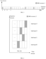
FIG. 3 is a schematic diagram of a frequency domain density of SRS resources according to an embodiment of the disclosure. -
FIG. 4 is a schematic diagram of another frequency domain density of SRS resources according to an embodiment of the disclosure. -
FIG. 5 is a schematic diagram of a physical architecture of an apparatus for obtaining uplink channel state information according to an embodiment of the disclosure. -
FIG. 6 is a schematic diagram of a logical architecture of an apparatus for obtaining uplink channel state information according to an embodiment of the disclosure. - In the NR system, in order to obtain a transmission path with a smaller delay to thereby design a port selection codebook with higher precision, in embodiments of the disclosure, the network side device configures at least one SRS resource for the terminal based on a preset bandwidth parameter, a preset frequency domain density parameter and a preset time domain parameters, and then measures an uplink channel based on at least one SRS to determine the uplink channel state information when receiving at least one SRS transmitted by the terminal using the at least one SRS resource.
- The preferred embodiments of the disclosure will be further described in detail below with reference to the accompanying drawings.
- Referring to
FIG. 2 , a process of obtaining the uplink channel state information in an embodiment of the disclosure is as follows. - S201: a network side device determines the SRS resource configuration information based on a preset bandwidth parameter, a preset frequency domain density parameter and a preset time domain parameter when determining to obtain the uplink channel state information.
- It should be noted that, in some embodiments of the disclosure, the uplink channel state information includes any one or a combination of angle information or delay information, where the angle information is used to characterize a signal emission angle and a signal arrival angle, and the delay information is used to characterize the time required for a signal to be sent from the terminal to the network side device.
- In some embodiments of the disclosure, the network side device includes but is not limited to a base station, a micro cell, etc. In the following, only the base station is taken as an example for description.
- The network side device determines to obtain the uplink channel state information when there are but not limited to the following cases.
- Case 1: the network side device determines to obtain the uplink channel state information when determining to schedule the uplink data transmission of the terminal based on a service request sent by the terminal.
- For example, the base station determines to obtain the angle information and delay information when determining to schedule the uplink data transmission of the terminal based on a service request sent by the terminal.
- Case 2: the network side device determines to obtain the uplink channel state information when determining the precoding matrix for the downlink data transmission based on a service request sent by the terminal.
- For example, the base station determines to obtain the angle information and delay information when determining the precoding matrix for the downlink data transmission based on a service request sent by the terminal.
- When determining to obtain the uplink channel state information, the network side device may configure the SRS resources by using, but not limited to, the following steps.
- A1. The network side device determines a bandwidth configuration of at least one SRS resource based on the preset bandwidth parameter.
- In an embodiment of the disclosure, the preset bandwidth parameter may be determined according to the maximum allowable uplink scheduled Bandwidth Part (BWP) or may be determined according to the downlink scheduled BWP, where the value of the preset bandwidth parameter is an integer multiple of 4, and the preset bandwidth parameter is not greater than the maximum value of the downlink scheduled BWP when the preset bandwidth parameter is determined according to the downlink scheduled BWP.
- For example, it is assumed that the preset bandwidth parameter is determined according to the maximum allowed uplink scheduled BWP, which is 256 PRBs. The base station determines the bandwidth configuration of the
SRS resource 1 as CSRS=57 and BSRS=0 based on the maximum allowed uplink scheduled BWP, where CSRS=57 and BSRS=0 indicate that the bandwidth of theSRS resource 1 is 256 PRBs, and theSRS resource 1 is sent in the non-frequency hopping manner. - For another example, it is assumed that the preset bandwidth parameter is determined according to the downlink scheduled BWP, which is 256 PRBs. The base station configures the bandwidth of the
SRS resource 1 as CSRS=57 and BSRS=2 based on the downlink scheduled BWP, where CSRS=57 and BSRS=2 indicate that the bandwidth of theSRS resource 1 is 256 PRBs, and theSRS resource 2 is sent in the frequency hopping manner. - A2. The network side device determines the frequency domain density of at least one SRS resource based on the preset frequency domain density parameter.
- In an embodiment of the disclosure, the preset frequency domain density parameter may be determined according to the frequency domain density of a downlink Channel State Information-Reference Signal (CSI-RS), or may be determined according to the sub-band size of a Precoding Matrix Indicator (PMI).
- In some embodiments, when the preset frequency domain density parameter is determined according to the sub-band size of the PMI, the sub-band size of the Channel Quality Indication (CQI) is


- For example, it is assumed that the preset frequency domain density parameter is determined according to the frequency domain density of the CSI-RS, which is 0.25RE/Resource Block (RB)/PORT. The base station determines the frequency domain density of the
SRS resource 1 as 0.25RE/RB/PORT based on the frequency domain density of the CSI-RS. - For another example, it is assumed that the preset frequency domain density parameter is determined according to the sub-band size of the PMI, where the sub-band size


SRS resource 2 as 0.25 RE/RB/PORT based on the sub-band sizes of the CQI and the PMI. - A3. The network side device determines a time domain parameter N corresponding to at least one SRS resource based on the type of a service request or the uplink channel quality information of a known terminal.
- In an embodiment of the disclosure, when the value of N is greater than 1, the terminal is instructed to send the at least one SRS in the frequency hopping manner on N OFDM symbols within one slot or across different slots; when the value of N is equal to 1, the terminal is instructed to send the at least one SRS in the frequency hopping manner across different slots.
- For example, the base station determines the value of the time domain parameter N of the
SRS resource 1 as 1 based on the type of the service request. The schematic diagram of the frequency domain density of theSRS resource 1 is shown inFIG. 3 , when the value of N is 1, the terminal is instructed to send theSRS 1 in the frequency hopping manner across different slots. - For another example, the base station determines the value of the time domain parameter N of the
SRS resource 2 as 4 based on the uplink channel quality information of the known terminal. The schematic diagram of the frequency domain density of theSRS resource 2 is shown inFIG. 4 , when the value of N is 4, the terminal is instructed to send theSRS 1 in the frequency hopping manner on 4 OFDM symbols in a slot. - A4. The network side device determines the SRS resource configuration information of at least one SRS resource based on the bandwidth configuration, the frequency domain density and the time domain parameter N.
- For example, the base station determines the SRS
resource configuration information 1 of theSRS resource 1 based on the bandwidth configuration of 256 PRBs, the frequency domain density of 0.25 RE/RB/PORT, and the time domain parameter N=1. - For another example, the base station determines the SRS
resource configuration information 2 of theSRS resource 2 based on the bandwidth configuration of 256 PRBs, the frequency domain density of 0.25 RE/RB/PORT, and the time domain parameter N=4. - It should be noted that, in some embodiments of the disclosure, it is also necessary to determine a period configuration corresponding to at least one SRS resource based on the preset time domain characteristics when determining the SRS resource configuration information of at least one SRS resource, where the period configuration is used to indicate that the SRS is sent in a periodic, semi-persistent or aperiodic manner.
- For example, the base station determines the
period configuration 1 of theSRS resource 1 based on the preset time domain characteristics, where theperiod configuration 1 indicates that theSRS 1 is sent in an aperiodic manner. - It should be noted that, in some embodiments of the disclosure, at least one SRS resource corresponding to the SRS resource configuration information may be included in a same SRS resource set or in different SRS resource sets, which is not limited in the disclosure.
- S202: the network side device sends the SRS resource configuration information to a terminal, and receives at least one SRS reported by the terminal based on the SRS resource configuration information.
- For example, the base station sends the SRS
resource configuration information 1 and SRSresource configuration information 2 to the terminal, and receives theSRS 1 and SRS2 reported by the terminal based on the SRSresource configuration information 1 and SRSresource configuration information 2. - S203: the network side device measures an uplink channel used by the terminal based on at least one SRS, and determines the corresponding uplink channel state information.
- In an embodiment of the disclosure, the uplink channel state information may be determined in but not limited to two following ways.
- In the first way: determine the uplink channel state information in a one-step way.
-
B 1. The network side device generates at least one uplink channel information corresponding to the at least one SRS by measuring the uplink channel used by the terminal based on at least one SRS. - It should be noted that, in the embodiment of the disclosure, the uplink channel information includes, but is not limited to, angle information, delay information, Doppler shift information, uplink channel signal amplitude, phase information, and other information. Since all the above-mentioned information is encapsulated in the uplink channel information, the uplink channel information needs to be further processed to obtain various information such as angle information and delay information.
- For example, the base station measures the uplink channel used by the terminal based on the
SRS 1 and SRS2, and generates theuplink channel information 1 corresponding to theSRS 1 and theuplink channel information 2 corresponding to the SRS2. - B2. The network side device determines a spatial domain basis vector and a frequency domain basis vector based on at least one uplink channel information.
- For example, the base station determines the spatial
domain basis vector 1 based on theuplink channel information 1, and determines the frequencydomain basis vector 1 based on theuplink channel information 2. - B3. The network side device determines the angle information and delay information of the uplink channel based on the spatial domain basis vector and the frequency domain basis vector.
- For example, the base station determines the
angle information 1 of the uplink channel based on the spatialdomain basis vector 1, and determines thedelay information 1 of the uplink channel based on the frequencydomain basis vector 1. - It should be noted that, in some embodiments of the disclosure, when the uplink channel state information is determined in the one-step manner, the
steps B 1, B2, and B3 are one step, and the step is broken down for clarity of description in the disclosure. - In the second way: determine the uplink channel state information in a two-step way.
- C1. The network side device generates at least one uplink channel information corresponding to the at least one SRS by measuring the uplink channel used by the terminal based on at least one SRS.
- For example, the base station measures the uplink channel used by the terminal based on the
SRS 1 and SRS2, and generates theuplink channel information 1 corresponding to theSRS 1 and theuplink channel information 2 corresponding to the SRS2. - C2. The network side device determines X spatial domain basis vectors based on the first uplink channel information included in the at least one uplink channel information, and determines the angle information of the uplink channel based on the X spatial domain basis vectors.
- For example, the base station determines 8 spatial
domain basis vectors 2 based on theuplink channel information 1, and determines theangle information 2 of the uplink channel based on the 8 spatialdomain basis vectors 2. - C3. The network side device takes the X spatial domain basis vectors as beams of a CSI-RS, and sends a beam-forming CSI-RS to the terminal through X ports so that the terminal selects L ports from the X ports.
- For example, the base station takes 8 spatial
domain basis vectors 2 as beams of the CSI-RS, and sends the beam-forming CSI-RS to the terminal through 8 ports, so that the terminal selects 4 ports from the 8 ports. - C4. The network side device receives the port indication information indicating the L ports returned by the terminal, and determines M frequency domain basis vectors based on the L ports and the second uplink channel information included in the at least one uplink channel information.
- For example, the base station receives the port indication information that is returned by the terminal and that characterizes 4 ports selected by the terminal, and determines 4 frequency
domain basis vectors 2 based on the 4 ports and theuplink channel information 2. - C5. The network side device determines the corresponding delay information based on the M frequency domain basis vectors.
- For example, the base station determines the
delay information 2 of the uplink channel based on 4 frequencydomain basis vectors 2. - It should be noted that, in some embodiments of the disclosure, the parameters such as R, N,


- It should be noted that, in some embodiments of the disclosure, when the uplink channel state information is determined in the two-step manner, the steps C1, C2, and C3 are the first step, and the steps C4 and C5 are the second step. Each step of operation is broken down for clarity of description in the disclosure.
- Next, taking the case that the network side device configures one SRS resource for the terminal as an example, the first way for the network side device to determine the uplink channel state information will be illustrated.
- It is assumed that the downlink scheduled BWP is 256 PRBs, the sub-band size

SRS resource 3 is CSRS=57 and BSRS=0 based on the downlink scheduled BWP, where CSRS=57 and BSRS=0 indicates that the bandwidth of theSRS resource 3 is 256 PRBs and theSRS resource 3 is sent in the non-frequency hopping manner. Then, the network side device determines that the frequency domain density k of theSRS resource 3 is 0.25 RE/RB/PORT based on the sub-band size of the PMI, and determines that the value of the time domain parameter N of theSRS resource 3 is 1 based on the uplink channel quality information of the known terminal. Next, the network side device determines the SRSresource configuration information 3 of theSRS resource 3 based on the bandwidth configuration, the frequency domain density k and the time domain parameter N. - The network side device sends the SRS
resource configuration information 3 to the terminal, and receives the SRS3 reported by the terminal based on the SRSresource configuration information 3. - The network side device measures the uplink channel used by the terminal based on the SRS3, and generates the
uplink channel information 3 corresponding to the SRS3. Then, the network side device determines the spatialdomain basis vector 3 and the frequencydomain basis vector 3 based on theuplink channel information 3, and determines theangle information 3 and thedelay information 3 of the uplink channel respectively based on the spatialdomain basis vector 3 and the frequencydomain basis vector 3. - Next, still taking the case that the network side device configures one SRS resource for the terminal as an example, the second way for the network side device to determine the uplink channel state information will be illustrated.
- It is assumed that the downlink scheduled BWP is 256 PRBs. When determining to obtain the uplink channel state information, the network side device determines the SRS
resource configuration information 3 of theSRS resource 3, where the bandwidth configuration of theSRS resource 3 is CSRS=57 and BSRS=0, the frequency domain density k of theSRS resource 3 is 0.25 RE/RB/PORT, and the value of the time domain parameter N of theSRS resource 3 is 1. Since the specific process of determining the bandwidth configuration, the frequency domain density k and the time domain parameter N of the SRS3 resource is the same as that in the above, which will not be repeated here. - The network side device sends the SRS
resource configuration information 3 to the terminal, and receives the SRS3 reported by the terminal based on the SRSresource configuration information 3. - The network side device measures the uplink channel used by the terminal based on the SRS3, and generates the
uplink channel information 3 corresponding to the SRS3. Then, the network side device determines 8 spatialdomain basis vectors 3 based on theuplink channel information 3, and determines theangle information 3 of the uplink channel based on the 8 spatialdomain basis vectors 3. Next, the network side device takes the 8 spatialdomain basis vectors 3 as beams of the CSI-RS, and sends a beam-forming CSI-RS to the terminal through 8 ports, so that the terminal selects 4 ports from the 8 ports. The network side device receives the port indication information that is returned by the terminal and that characterizes 4 ports selected by the terminal, and determines 4 frequencydomain basis vectors 3 based on the 4 ports and theuplink channel information 3. After that, the network side device determines thedelay information 3 of the uplink channel based on the 4 frequencydomain basis vectors 3. - Next, taking the case that the network side device configures two SRS resources for the terminal as an example, the first way for the network side device to determine the uplink channel state information will be illustrated, where the resource configuration method in the prior art is used for one SRS resource, and the resource configuration method provided in the disclosure is used for the other SRS resource.
- It is assumed that the downlink scheduled BWP is 256 PRBs. When determining to obtain the uplink channel state information, the network side device firstly configures the bandwidth of the SRS resource 4 as CSRS=14 and BSRS=0 and sets the value of the Comb parameter as 2 based on the resource configuration method in the prior art, where CSRS=14 and BSRS=0 indicates that the bandwidth of the
SRS resource 1 is 52 PRBs and the SRS resource 4 is sent in the non-frequency hopping manner, and the value of the Comb parameter being 2 indicates that SRS resource 4 is transmitted at every other subcarrier in the frequency domain. Then, the network side device determines the resource configuration information 4 of the SRS resource 4 based on the bandwidth configuration of the SRS resource 4 and the value of the Comb parameter. At the same time, the network side device determines the SRSresource configuration information 3 of theSRS resource 3 based on the downlink scheduled BWP, the sub-band size of the PMI and the uplink channel quality information of the known terminal, where the bandwidth configuration of theSRS resource 3 is CSRS=57 and BSRS=0, the frequency domain density k of theSRS resource 3 is 0.25 RE/RB/PORT, and the value of the time domain parameter N of theSRS resource 3 is 1. Since the specific process of determining the bandwidth configuration, the frequency domain density k and the time domain parameter N of the SRS3 resource is the same as that in the above, which will not be repeated here. - The network side device sends the SRS
resource configuration information 3 and SRS resource configuration information 4 to the terminal, and receives the SRS3 and SRS4 reported by the terminal based on the SRSresource configuration information 3 and SRS resource configuration information 4. - The network side device measures the uplink channel used by the terminal based on the SRS3 and SRS4, and generates the
uplink channel information 3 corresponding to the SRS1 and the uplink channel information 4 corresponding to the SRS4. Then, the network side device determines the spatial domain basis vector 4 based on the uplink channel information 4, and determines the frequency domain basis vector 4 based on theuplink channel information 1. Then, the network side device determines the angle information 4 of the uplink channel based on the spatial domain basis vector 4, and determines the delay information of the uplink channel based on the frequency domain basis vector 4. - Next, taking the case that the network side device configures two SRS resources for the terminal as an example, the second way for the network side device to determine the uplink channel state information will be illustrated, where the resource configuration method in the prior art is used for one SRS resource, and the resource configuration method provided in the disclosure is used for the other SRS resource.
- It is assumed that the downlink scheduled BWP is 256 PRBs. When determining to obtain the uplink channel state information, the network side device firstly configures the bandwidth of the SRS resource 4 as CSRS=14 and BSRS=0 and sets the value of the Comb parameter as 2 based on the resource configuration method in the prior art, where CSRS=14 and BSRS=0 indicates that the bandwidth of the
SRS resource 1 is 52 PRBs and the SRS resource 4 is sent in the non-frequency hopping manner, and the value of the Comb parameter being 2 indicates that SRS resource 4 is transmitted at every other subcarrier in the frequency domain. Then, the network side device determines the resource configuration information 4 of the SRS resource 4 based on the bandwidth configuration of the SRS resource 4 and the value of the Comb parameter. At the same time, the network side device determines the SRSresource configuration information 3 of theSRS resource 3 based on the downlink scheduled BWP, the sub-band size of the PMI and the uplink channel quality information of the known terminal, where the bandwidth configuration of theSRS resource 3 is CSRS=57 and BSRS=0, the frequency domain density k of theSRS resource 3 is 0.25 RE/RB/PORT, and the value of the time domain parameter N of theSRS resource 3 is 1. Since the specific process of determining the bandwidth configuration, the frequency domain density k and the time domain parameter N of the SRS3 resource is the same as that in the above, which will not be repeated here. - The network side device sends the SRS
resource configuration information 3 and SRS resource configuration information 4 to the terminal, and receives the SRS3 and SRS4 returned by the terminal based on the SRSresource configuration information 3 and SRS resource configuration information 4. - The network side device measures the uplink channel used by the terminal based on the SRS3 and SRS4, and generates the
uplink channel information 3 corresponding to the SRS3 and the uplink channel information 4 corresponding to the SRS4. Then, the network side device determines 8 spatial domain basis vectors 5 based on the uplink channel information 4, and determines the angle information 5 of the uplink channel based on the 8 spatial domain basis vectors 5. Next, the network side device takes the 8 spatial domain basis vectors 5 as beams of the CSI-RS, and sends a beam-forming CSI-RS to the terminal through 8 ports, so that the terminal selects 4 ports from the 8 ports. The network side device receives the port indication information that is returned by the terminal and that characterizes 4 ports selected by the terminal, and determines 4 frequency domain basis vectors 5 based on the 4 ports and theuplink channel information 3. After that, the network side device determines the delay information 5 of the uplink channel based on the 4 frequency domain basis vectors 5. - Based on the same inventive concept, referring to
FIG. 5 , an embodiment of the disclosure provides an apparatus for obtaining uplink channel state information, including at least: - a
memory 501 configured to store executable instructions; - a
processor 502 configured to read and execute the executable instructions stored in the memory to perform the process of:- determining SRS resource configuration information based on a preset bandwidth parameter, a preset frequency domain density parameter and a preset time domain parameter when determining to obtain the uplink channel state information;
- sending the SRS resource configuration information to a terminal, and receiving at least one SRS reported by the terminal based on the SRS resource configuration information;
- measuring an uplink channel used by the terminal based on the at least one SRS, and determining the corresponding uplink channel state information.
- In some embodiments, the uplink channel state information includes angle information and/or delay information, where the angle information is used to characterize a signal emission angle and a signal arrival angle, and the delay information is used to characterize the time required for a signal to be sent from the terminal to the network side device.
- In some embodiments, the preset bandwidth parameter is determined according to a maximum allowed uplink scheduled BWP or downlink scheduled BWP, and the preset frequency domain density parameter is determined according to a frequency domain density of a downlink CSI-RS or a sub-band size of a PMI, where a value of the preset bandwidth parameter is an integer multiple of 4, and the preset bandwidth parameter is not greater than a maximum value of the downlink scheduled BWP when the preset bandwidth parameter is determined according to the downlink scheduled BWP.
- In some embodiments, when determining the SRS resource configuration information based on the preset bandwidth parameter, the preset frequency domain density parameter and the preset time domain parameter, the
processor 502 is specifically configured to: - determine a bandwidth configuration of at least one SRS resource based on the preset bandwidth parameter;
- determine a frequency domain density of the at least one SRS resource based on the preset frequency domain density parameter;
- determine a time domain parameter N corresponding to the at least one SRS resource based on a type of a service request or uplink channel quality information of a known terminal;
- determine the SRS resource configuration information of the at least one SRS resource based on the bandwidth configuration, the frequency domain density and the time domain parameter N;
- when a value of N is greater than 1, the terminal is instructed to send the at least one SRS in a frequency hopping manner on N Orthogonal Frequency Division Multiplexing, OFDM, symbols within one slot or across different slots; when the value of N is equal to 1, the terminal is instructed to send the at least one SRS in the frequency hopping manner across different slots.
- In some embodiments, when measuring the uplink channel used by the terminal based on the at least one SRS and determining the corresponding uplink channel state information, the
processor 502 is specifically configured to: - generate at least one uplink channel information corresponding to the at least one SRS by measuring the uplink channel used by the terminal based on the at least one SRS;
- determine the corresponding uplink channel state information by:
- determining X spatial domain basis vectors based on first uplink channel information included in the at least one uplink channel information, and determining angle information of the uplink channel based on the X spatial domain basis vectors; taking the X spatial domain basis vectors as beams of a CSI-RS, and sending a beam-forming CSI-RS to the terminal through X ports so that the terminal selects L ports from the X ports;
- receiving port indication information characterizing the L ports returned by the terminal, and determining M frequency domain basis vectors based on the L ports and second uplink channel information included in the at least one uplink channel information; determining delay information of the uplink channel based on the M frequency domain basis vectors;
- where X, L, and M are preset integers, and the first uplink channel information is same as the second uplink channel information, or the first uplink channel information is different from the second uplink channel information.
- In some embodiments, when measuring the uplink channel used by the terminal based on the at least one SRS and determining the corresponding uplink channel state information, the
processor 502 is specifically configured to: - generate at least one uplink channel information corresponding to the at least one SRS by measuring the uplink channel used by the terminal based on the at least one SRS;
- determine the corresponding uplink channel state information by:
determining a spatial domain basis vector and a frequency domain basis vector based on the at least one uplink channel information, and determining angle information and delay information of the uplink channel based on the spatial domain basis vector and the frequency domain basis vector. Atransceiver 503 is configured to receive and send the data under the control of theprocessor 502. - Here, in
FIG. 5 , the bus architecture may include any numbers of interconnected buses and bridges, and specifically link various circuits of one or more processors represented by theprocessor 502 and the memory represented by thememory 501. The bus architecture may further link various other circuits such as peripheral device, voltage regulator and power management circuit, which are all well known in the art and thus will not be further described again herein. The bus interface provides an interface. Thetransceiver 503 may be a plurality of elements, i.e., include a transmitter and a receiver, and provide the units for communicating with various other devices over the transmission media. Theprocessor 502 is responsible for managing the bus architecture and general processing, and thememory 501 may store the data used by theprocessor 502 when performing the operations. - Based on the same inventive concept, an embodiment of the disclosure provides an apparatus for obtaining uplink channel state information, as shown in
FIG. 6 , which at least includes: aconfiguration unit 601, a sendingunit 602 and aprocessing unit 603; - the
configuration unit 601 is configured to determine SRS resource configuration information based on a preset bandwidth parameter, a preset frequency domain density parameter and a preset time domain parameter when determining to obtain the uplink channel state information; - the sending
unit 602 is configured to send the SRS resource configuration information to a terminal, and receive at least one SRS reported by the terminal based on the SRS resource configuration information; - the
processing unit 603 is configured to measure an uplink channel used by the terminal based on the at least one SRS, and determine the corresponding uplink channel state information. - The
configuration unit 601, the sendingunit 602 and theprocessing unit 603 cooperate with each other to realize the functions of the apparatus for obtaining the uplink channel state information in the above embodiments. - Based on the same inventive concept, an embodiment of the disclosure provides a storage medium, where the instructions in the storage medium, when executed by a processor, enable the processor to perform any method implemented by the apparatus for obtaining the uplink channel state information in the above process.
- To sum up, in some embodiments of the disclosure, the network side device generates the SRS resource configuration information based on the preset bandwidth parameter, the preset frequency domain density parameter and the preset time domain parameter, and then the network side device measures the uplink channel used by the terminal based on at least one SRS returned by the terminal, and determines the corresponding uplink channel state information. In this way, the SRS resource configuration information is generated through the frequency domain density parameter. The frequency domain density of the SRS resource can be adjusted, that is, the frequency domain density of the SRS resource can be reduced. Since the frequency domain density is reduced, the signal to interference plus noise ratio of each SRS RE can be improved compared with the existing SRS resource allocation method, thereby increasing the coverage of the SRS. At the same time, the bandwidth of SRS resource configuration can be increased through the bandwidth parameter, so that the network side device can capture the transmission paths with different delays, thereby designing a port selection codebook with higher precision.
- For the system/apparatus embodiments, they are substantially similar to the method embodiments, so the description thereof is relatively simple, and the related parts may refer to the partial illustration of the method embodiments.
- It should be noted that the relational terms such as first and second herein are only used to distinguish one entity or operation from another and do not necessarily require or imply any such actual relationship or sequence between these entities or operations.
- It should be understood by those skilled in the art that the embodiments of the disclosure can be provided as methods, systems and computer program products. Thus the disclosure can take the form of hardware embodiments alone, software embodiments alone, or embodiments combining the software and hardware aspects. Also the disclosure can take the form of computer program products implemented on one or more computer usable storage mediums (including but not limited to magnetic disk memories, CD-ROMs, optical memories and the like) containing computer usable program codes therein.
- The disclosure is described by reference to the flow charts and/or the block diagrams of the methods, the devices (systems) and the computer program products according to the embodiments of the disclosure. It should be understood that each process and/or block in the flow charts and/or the block diagrams, and a combination of processes and/or blocks in the flow charts and/or the block diagrams can be implemented by the computer program instructions. These computer program instructions can be provided to a general-purpose computer, a dedicated computer, an embedded processor, or a processor of another programmable data processing device to produce a machine, so that an apparatus for implementing the functions specified in one or more processes of the flow charts and/or one or more blocks of the block diagrams is produced by the instructions executed by the computer or the processor of another programmable data processing device.
- These computer program instructions can also be stored in a computer readable memory which is capable of guiding the computer or another programmable data processing device to operate in a particular way, so that the instructions stored in the computer readable memory produce a manufacture including the instruction apparatus which implements the functions specified in one or more processes of the flow charts and/or one or more blocks of the block diagrams.
- These computer program instructions can also be loaded onto the computer or another programmable data processing device, so that a series of operation steps are performed on the computer or another programmable device to produce the computer-implemented processing. Thus the instructions executed on the computer or another programmable device provide steps for implementing the functions specified in one or more processes of the flow charts and/or one or more blocks of the block diagrams.
- Although the preferred embodiments of the disclosure have been described, those skilled in the art can make additional alterations and modifications to these embodiments once they learn about the basic creative concepts. Thus, the attached claims are intended to be interpreted to include the preferred embodiments as well as all the alterations and modifications falling within the scope of the disclosure.
- Evidently those skilled in the art can make various modifications and variations to the disclosure without departing from the spirit and scope of the disclosure. Thus the disclosure is also intended to encompass these modifications and variations to the disclosure as long as these modifications and variations come into the scope of the claims of the disclosure and their equivalents.
Claims (12)
- A method for obtaining uplink channel state information, comprising:determining, by a network side device, Sounding Reference Signal, SRS, resource configuration information based on a preset bandwidth parameter, a preset frequency domain density parameter and a preset time domain parameter, in a case that the network side device determines to obtain the uplink channel state information;sending, by the network side device, the SRS resource configuration information to a terminal;receiving, by the network side device, at least one SRS reported by the terminal based on the SRS resource configuration information; andmeasuring, by the network side device, an uplink channel used by the terminal based on the at least one SRS, and determining the corresponding uplink channel state information.
- The method according to claim 1, wherein:the preset bandwidth parameter is determined according to a maximum allowed uplink scheduled Bandwidth Part, BWP, or a maximum allowed downlink scheduled BWP; andthe preset frequency domain density parameter is determined according to a frequency domain density of a downlink Channel State Information-Reference Signal, CSI-RS, or a sub-band size of a Precoding Matrix Indicator, PMI;wherein a value of the preset bandwidth parameter is an integer multiple of 4, and the preset bandwidth parameter is not greater than a maximum value of the downlink scheduled BWP in a case that the value of the preset bandwidth parameter is determined according to the downlink scheduled BWP.
- The method according to claim 1 or 2, wherein, the determining, by the network side device, the SRS resource configuration information based on the preset bandwidth parameter, the preset frequency domain density parameter and the preset time domain parameter, further comprises:determining, by the network side device, a bandwidth configuration of at least one SRS resource based on the preset bandwidth parameter;determining, by the network side device, a frequency domain density of the at least one SRS resource based on the preset frequency domain density parameter;determining, by the network side device, a time domain parameter N corresponding to the at least one SRS resource based on a type of a service request or uplink channel quality information of a known terminal; anddetermining, by the network side device, the SRS resource configuration information of the at least one SRS resource based on the bandwidth configuration, the frequency domain density and the time domain parameter N;wherein the terminal is instructed to send the at least one SRS in a frequency hopping manner on N Orthogonal Frequency Division Multiplexing, OFDM, symbols within one slot or across different slots in response to a value of N being greater than 1;the terminal is instructed to send the at least one SRS in a frequency hopping manner across different slots in response to a value of N being equal to 1.
- The method according to claim 1 or 2, wherein, the measuring, by the network side device, the uplink channel used by the terminal based on the at least one SRS, and determining the corresponding uplink channel state information, comprises:generating, by the network side device, at least one uplink channel information corresponding to the at least one SRS by measuring the uplink channel used by the terminal based on the at least one SRS;determining, by the network side device, the corresponding uplink channel state information by:determining, by the network side device, X spatial domain basis vectors based on first uplink channel information included in the at least one uplink channel information;determining, by the network side device, angle information in the uplink channel state information based on the X spatial domain basis vectors;taking, by the network side device, the X spatial domain basis vectors as beams of a CSI-RS;sending, by the network side device, a beam-forming CSI-RS to the terminal through X ports to select L ports from the X ports by the terminal;receiving, by the network side device, port indication information indicating the L ports returned by the terminal;determining, by the network side device, M frequency domain basis vectors based on the L ports and second uplink channel information included in the at least one uplink channel information; anddetermining, by the network side device, delay information in the uplink channel state information based on the M frequency domain basis vectors;wherein X, L, and M are preset integers, and the first uplink channel information is same as the second uplink channel information, or the first uplink channel information is different from the second uplink channel information.
- The method according to claim 1 or 2, wherein, the measuring, by the network side device, the uplink channel used by the terminal based on the at least one SRS, and determining the corresponding uplink channel state information, further comprises:generating, by the network side device, at least one uplink channel information corresponding to the at least one SRS by measuring the uplink channel used by the terminal based on the at least one SRS;determining, by the network side device, the corresponding uplink channel state information by:determining, by the network side device, a spatial domain basis vector and a frequency domain basis vector based on the at least one uplink channel information; anddetermining, by the network side device, angle information and delay information in the uplink channel state information based on the spatial domain basis vector and the frequency domain basis vector.
- An apparatus for obtaining uplink channel state information, comprising:a memory configured to store executable instructions;a processor configured to read and execute the executable instructions stored in the memory to perform a process of:determining Sounding Reference Signal, SRS, resource configuration information based on a preset bandwidth parameter, a preset frequency domain density parameter and a preset time domain parameter, in a case that determining to obtain the uplink channel state information;sending the SRS resource configuration information to a terminal;receiving at least one SRS reported by the terminal based on the SRS resource configuration information; andmeasuring an uplink channel used by the terminal based on the at least one SRS, and determining the corresponding uplink channel state information.
- The apparatus according to claim 6, wherein:the preset bandwidth parameter is determined according to a maximum allowed uplink scheduled Bandwidth Part, BWP, or a maximum allowed downlink scheduled BWP; andthe preset frequency domain density parameter is determined according to a frequency domain density of a downlink Channel State Information-Reference Signal, CSI-RS, or a sub-band size of a Precoding Matrix Indicator, PMI;wherein a value of the preset bandwidth parameter is an integer multiple of 4, and the preset bandwidth parameter is not greater than a maximum value of the downlink scheduled BWP, in a case that the value of the preset bandwidth parameter is determined according to the downlink scheduled BWP.
- The apparatus according to claim 6 or 7, wherein in a case that the SRS resource configuration information is determined based on the preset bandwidth parameter, the preset frequency domain density parameter and the preset time domain parameter, the processor is further configured to:determine a bandwidth configuration of at least one SRS resource based on the preset bandwidth parameter;determine a frequency domain density of the at least one SRS resource based on the preset frequency domain density parameter;determine a time domain parameter N corresponding to the at least one SRS resource based on a type of a service request or uplink channel quality information of a known terminal; anddetermine the SRS resource configuration information of the at least one SRS resource based on the bandwidth configuration, the frequency domain density and the time domain parameter N;wherein the terminal is instructed to send the at least one SRS in a frequency hopping manner on N Orthogonal Frequency Division Multiplexing, OFDM, symbols within one slot or across different slots in response to a value of N being greater than 1;the terminal is instructed to send the at least one SRS in a frequency hopping manner across different slots in response to a value of N being equal to 1.
- The apparatus according to claim 6 or 7, wherein in a case that the uplink channel used by the terminal is measured based on the at least one SRS and the corresponding uplink channel state information is determined, the processor is further configured to:generate at least one uplink channel information corresponding to the at least one SRS by measuring the uplink channel used by the terminal based on the at least one SRS;determine the corresponding uplink channel state information by:determining X spatial domain basis vectors based on first uplink channel information included in the at least one uplink channel information;determining angle information in the uplink channel state information based on the X spatial domain basis vectors;taking the X spatial domain basis vectors as beams of a CSI-RS;sending a beam-forming CSI-RS to the terminal through X ports to select L ports from the X ports by the terminal;receiving port indication information indicating the L ports returned by the terminal;determining M frequency domain basis vectors based on the L ports and second uplink channel information included in the at least one uplink channel information; anddetermining delay information in the uplink channel state information based on the M frequency domain basis vectors;wherein X, L, and M are preset integers, and the first uplink channel information is same as the second uplink channel information, or the first uplink channel information is different from the second uplink channel information.
- The apparatus according to claim 6 or 7, wherein in a case that the uplink channel used by the terminal is measured based on the at least one SRS and the corresponding uplink channel state information is determined, the processor is further configured to:generate at least one uplink channel information corresponding to the at least one SRS by measuring the uplink channel used by the terminal based on the at least one SRS;determine the corresponding uplink channel state information by:determining a spatial domain basis vector and a frequency domain basis vector based on the at least one uplink channel information, anddetermining angle information and delay information in the uplink channel state information based on the spatial domain basis vector and the frequency domain basis vector.
- An apparatus for obtaining uplink channel state information, comprising:a configuration unit, configured to determine Sounding Reference Signal, SRS, resource configuration information based on a preset bandwidth parameter, a preset frequency domain density parameter and a preset time domain parameter, in a case that determining to obtain the uplink channel state information;a sending unit, configured to send the SRS resource configuration information to a terminal, and receive at least one SRS reported by the terminal based on the SRS resource configuration information;a processing unit, configured to measure an uplink channel used by the terminal based on the at least one SRS, and determine the corresponding uplink channel state information.
- A storage medium storing instructions, wherein the instructions, when executed by a processor, enable the processor to perform the method for obtaining uplink channel state information according to any one of claims 1 to 5.
Applications Claiming Priority (2)
| Application Number | Priority Date | Filing Date | Title |
|---|---|---|---|
| CN202010412184.8A CN113677007B (en) | 2020-05-15 | 2020-05-15 | A method and device for obtaining uplink channel state information |
| PCT/CN2021/081354 WO2021227648A1 (en) | 2020-05-15 | 2021-03-17 | Method and apparatus for acquiring uplink channel state information |
Publications (4)
| Publication Number | Publication Date |
|---|---|
| EP4152857A1 true EP4152857A1 (en) | 2023-03-22 |
| EP4152857A4 EP4152857A4 (en) | 2023-11-01 |
| EP4152857B1 EP4152857B1 (en) | 2025-08-06 |
| EP4152857C0 EP4152857C0 (en) | 2025-08-06 |
Family
ID=78526331
Family Applications (1)
| Application Number | Title | Priority Date | Filing Date |
|---|---|---|---|
| EP21804785.0A Active EP4152857B1 (en) | 2020-05-15 | 2021-03-17 | Method and apparatus for acquiring uplink channel state information |
Country Status (4)
| Country | Link |
|---|---|
| US (1) | US12556330B2 (en) |
| EP (1) | EP4152857B1 (en) |
| CN (1) | CN113677007B (en) |
| WO (1) | WO2021227648A1 (en) |
Families Citing this family (3)
| Publication number | Priority date | Publication date | Assignee | Title |
|---|---|---|---|---|
| CN116455534A (en) * | 2022-01-06 | 2023-07-18 | 维沃移动通信有限公司 | Channel measurement method, terminal and network side equipment |
| CN117528779A (en) * | 2022-07-25 | 2024-02-06 | 维沃移动通信有限公司 | Information configuration method, device, terminal, network side equipment and readable storage medium |
| CN121646960A (en) * | 2023-09-13 | 2026-03-10 | 华为技术有限公司 | Method for feeding back channel state information and communication device |
Family Cites Families (20)
| Publication number | Priority date | Publication date | Assignee | Title |
|---|---|---|---|---|
| CN101674655A (en) * | 2009-10-14 | 2010-03-17 | 中兴通讯股份有限公司 | Method and system for acquiring information of uplink channel and downlink channel |
| CN103945541B (en) * | 2010-02-11 | 2017-09-19 | 电信科学技术研究院 | Trigger method and equipment that SRS signal is sent |
| KR101460331B1 (en) | 2012-12-11 | 2014-11-11 | 주식회사 케이티 | Mobile communication system and method for allocating wireless resource based on multicell |
| CN104079373B (en) * | 2013-03-28 | 2017-11-24 | 华为技术有限公司 | Method and device for determining uplink channel state information |
| CN110247748B (en) * | 2016-02-26 | 2021-06-22 | 北京佰才邦技术有限公司 | Sounding reference signal transmission method, device and terminal |
| WO2018062841A1 (en) * | 2016-09-29 | 2018-04-05 | 엘지전자 주식회사 | Method for transmitting and receiving signal between terminal and base station in wireless communication system, and apparatus for supporting same |
| WO2018128504A1 (en) | 2017-01-08 | 2018-07-12 | 엘지전자(주) | Uplink transmission/reception method in wireless communication system, and device therefor |
| CN108632008B (en) * | 2017-03-24 | 2023-06-02 | 华为技术有限公司 | A reference signal sending method and device |
| CN113489577B (en) * | 2017-08-09 | 2023-03-24 | 中兴通讯股份有限公司 | Indication method of reference signal configuration information, base station and terminal |
| CN107911203B (en) * | 2017-08-11 | 2023-11-14 | 华为技术有限公司 | Methods, network equipment, terminal equipment and systems for transmitting and receiving reference signals |
| CN109391304B (en) | 2017-08-11 | 2020-11-27 | 电信科学技术研究院 | A data transmission method, base station, terminal and storage medium |
| CN109802810B (en) * | 2017-11-17 | 2021-07-09 | 华为技术有限公司 | Method and apparatus for sending sounding reference signal SRS |
| EP3711266B1 (en) * | 2017-11-17 | 2022-06-15 | Telefonaktiebolaget LM Ericsson (Publ) | Systems and methods regarding frequency-selective srs transmission and pusch precoding |
| US10863494B2 (en) * | 2018-01-22 | 2020-12-08 | Apple Inc. | Control signaling for uplink multiple input multiple output, channel state information reference signal configuration and sounding reference signal configuration |
| US11166267B2 (en) * | 2018-08-17 | 2021-11-02 | Qualcomm Incorporated | DCI triggered SRS enhancements |
| CN113438062B (en) * | 2018-10-22 | 2023-06-02 | 成都华为技术有限公司 | Method and device for determining measured value of reference signal |
| EP4224732A1 (en) * | 2018-12-12 | 2023-08-09 | Telefonaktiebolaget LM Ericsson (publ) | Reporting of coefficients for channel state information |
| CN113243135A (en) * | 2018-12-25 | 2021-08-10 | 华为技术有限公司 | Method and device for acquiring downlink channel information |
| US11284417B2 (en) * | 2019-04-11 | 2022-03-22 | Qualcomm Incorporated | Scheduling based on available transmit power and channel state |
| EP3970276A4 (en) * | 2019-07-22 | 2022-08-03 | Guangdong Oppo Mobile Telecommunications Corp., Ltd. | METHOD AND DEVICE FOR FREQUENCY-SELECTIVE PRECODING FOR PHYSICAL TRANSMISSION IN A COMMON UPLINK CHANNEL |
-
2020
- 2020-05-15 CN CN202010412184.8A patent/CN113677007B/en active Active
-
2021
- 2021-03-17 US US17/925,315 patent/US12556330B2/en active Active
- 2021-03-17 WO PCT/CN2021/081354 patent/WO2021227648A1/en not_active Ceased
- 2021-03-17 EP EP21804785.0A patent/EP4152857B1/en active Active
Also Published As
| Publication number | Publication date |
|---|---|
| CN113677007A (en) | 2021-11-19 |
| US12556330B2 (en) | 2026-02-17 |
| US20230198711A1 (en) | 2023-06-22 |
| CN113677007B (en) | 2024-04-23 |
| EP4152857B1 (en) | 2025-08-06 |
| EP4152857C0 (en) | 2025-08-06 |
| EP4152857A4 (en) | 2023-11-01 |
| WO2021227648A1 (en) | 2021-11-18 |
Similar Documents
| Publication | Publication Date | Title |
|---|---|---|
| US11863252B2 (en) | Terminal device capability transmission method, apparatus, and system | |
| EP4280469A1 (en) | Channel state information transmission method and apparatus, electronic device, and storage medium | |
| US11483117B2 (en) | Method and device for configuring channel state information reference signal, and method and device for parsing configuring channel state information reference signal | |
| US10911176B2 (en) | Method and apparatus for reporting channel state information | |
| EP4152857B1 (en) | Method and apparatus for acquiring uplink channel state information | |
| JP7662660B2 (en) | Method and apparatus for determining spatial parameters | |
| CN102546110A (en) | Channel state information transmission method and device | |
| EP4178294A1 (en) | Method and apparatus for beam training | |
| US11489574B2 (en) | Method and user equipment for transmitting channel state information | |
| EP4044448A1 (en) | Csi measurement method and apparatus | |
| TWI807902B (en) | Methods and user equipment for mobile communications | |
| CN105991267B (en) | A kind of channel measuring method and device | |
| US10833746B2 (en) | Method for transmitting a channel state information-reference signal, processor, base station and storage medium | |
| KR20240102918A (en) | Channel status information reporting | |
| EP4395218A1 (en) | Information transmission method, device, and storage medium | |
| EP4311139A1 (en) | Channel state information reporting method, channel state information receiving method, communication node, and storage medium | |
| WO2024031673A1 (en) | Transmission precoder determination and spatial relation indication | |
| JP2025511433A (en) | SYSTEM AND METHOD FOR ENHANCED CHANNEL STATE INFORMATION REPORTING - Patent application | |
| KR20240041375A (en) | How to report information, how to receive information, devices and recording media | |
| WO2024031672A1 (en) | Simultaneous uplink transmission in multiple transmit-receive point configuration | |
| CN117411601A (en) | A DMRS resource allocation method, base station and device |
Legal Events
| Date | Code | Title | Description |
|---|---|---|---|
| STAA | Information on the status of an ep patent application or granted ep patent |
Free format text: STATUS: THE INTERNATIONAL PUBLICATION HAS BEEN MADE |
|
| PUAI | Public reference made under article 153(3) epc to a published international application that has entered the european phase |
Free format text: ORIGINAL CODE: 0009012 |
|
| STAA | Information on the status of an ep patent application or granted ep patent |
Free format text: STATUS: REQUEST FOR EXAMINATION WAS MADE |
|
| 17P | Request for examination filed |
Effective date: 20221208 |
|
| AK | Designated contracting states |
Kind code of ref document: A1 Designated state(s): AL AT BE BG CH CY CZ DE DK EE ES FI FR GB GR HR HU IE IS IT LI LT LU LV MC MK MT NL NO PL PT RO RS SE SI SK SM TR |
|
| DAV | Request for validation of the european patent (deleted) | ||
| DAX | Request for extension of the european patent (deleted) | ||
| A4 | Supplementary search report drawn up and despatched |
Effective date: 20231005 |
|
| RIC1 | Information provided on ipc code assigned before grant |
Ipc: H04B 17/364 20150101ALI20230928BHEP Ipc: H04L 5/00 20060101ALI20230928BHEP Ipc: H04W 72/04 20230101AFI20230928BHEP |
|
| GRAP | Despatch of communication of intention to grant a patent |
Free format text: ORIGINAL CODE: EPIDOSNIGR1 |
|
| STAA | Information on the status of an ep patent application or granted ep patent |
Free format text: STATUS: GRANT OF PATENT IS INTENDED |
|
| INTG | Intention to grant announced |
Effective date: 20250228 |
|
| GRAS | Grant fee paid |
Free format text: ORIGINAL CODE: EPIDOSNIGR3 |
|
| GRAA | (expected) grant |
Free format text: ORIGINAL CODE: 0009210 |
|
| STAA | Information on the status of an ep patent application or granted ep patent |
Free format text: STATUS: THE PATENT HAS BEEN GRANTED |
|
| AK | Designated contracting states |
Kind code of ref document: B1 Designated state(s): AL AT BE BG CH CY CZ DE DK EE ES FI FR GB GR HR HU IE IS IT LI LT LU LV MC MK MT NL NO PL PT RO RS SE SI SK SM TR |
|
| REG | Reference to a national code |
Ref country code: GB Ref legal event code: FG4D |
|
| REG | Reference to a national code |
Ref country code: CH Ref legal event code: EP |
|
| REG | Reference to a national code |
Ref country code: IE Ref legal event code: FG4D |
|
| REG | Reference to a national code |
Ref country code: DE Ref legal event code: R096 Ref document number: 602021035741 Country of ref document: DE |
|
| U01 | Request for unitary effect filed |
Effective date: 20250819 |
|
| U07 | Unitary effect registered |
Designated state(s): AT BE BG DE DK EE FI FR IT LT LU LV MT NL PT RO SE SI Effective date: 20250826 |
|
| PG25 | Lapsed in a contracting state [announced via postgrant information from national office to epo] |
Ref country code: IS Free format text: LAPSE BECAUSE OF FAILURE TO SUBMIT A TRANSLATION OF THE DESCRIPTION OR TO PAY THE FEE WITHIN THE PRESCRIBED TIME-LIMIT Effective date: 20251206 |
|
| PG25 | Lapsed in a contracting state [announced via postgrant information from national office to epo] |
Ref country code: NO Free format text: LAPSE BECAUSE OF FAILURE TO SUBMIT A TRANSLATION OF THE DESCRIPTION OR TO PAY THE FEE WITHIN THE PRESCRIBED TIME-LIMIT Effective date: 20251106 |
|
| PG25 | Lapsed in a contracting state [announced via postgrant information from national office to epo] |
Ref country code: HR Free format text: LAPSE BECAUSE OF FAILURE TO SUBMIT A TRANSLATION OF THE DESCRIPTION OR TO PAY THE FEE WITHIN THE PRESCRIBED TIME-LIMIT Effective date: 20250806 |
|
| PG25 | Lapsed in a contracting state [announced via postgrant information from national office to epo] |
Ref country code: GR Free format text: LAPSE BECAUSE OF FAILURE TO SUBMIT A TRANSLATION OF THE DESCRIPTION OR TO PAY THE FEE WITHIN THE PRESCRIBED TIME-LIMIT Effective date: 20251107 |
|
| PG25 | Lapsed in a contracting state [announced via postgrant information from national office to epo] |
Ref country code: PL Free format text: LAPSE BECAUSE OF FAILURE TO SUBMIT A TRANSLATION OF THE DESCRIPTION OR TO PAY THE FEE WITHIN THE PRESCRIBED TIME-LIMIT Effective date: 20250806 |
|
| PG25 | Lapsed in a contracting state [announced via postgrant information from national office to epo] |
Ref country code: RS Free format text: LAPSE BECAUSE OF FAILURE TO SUBMIT A TRANSLATION OF THE DESCRIPTION OR TO PAY THE FEE WITHIN THE PRESCRIBED TIME-LIMIT Effective date: 20251106 |
|
| PG25 | Lapsed in a contracting state [announced via postgrant information from national office to epo] |
Ref country code: ES Free format text: LAPSE BECAUSE OF FAILURE TO SUBMIT A TRANSLATION OF THE DESCRIPTION OR TO PAY THE FEE WITHIN THE PRESCRIBED TIME-LIMIT Effective date: 20250806 |
|
| PG25 | Lapsed in a contracting state [announced via postgrant information from national office to epo] |
Ref country code: SM Free format text: LAPSE BECAUSE OF FAILURE TO SUBMIT A TRANSLATION OF THE DESCRIPTION OR TO PAY THE FEE WITHIN THE PRESCRIBED TIME-LIMIT Effective date: 20250806 |
|
| PGFP | Annual fee paid to national office [announced via postgrant information from national office to epo] |
Ref country code: GB Payment date: 20260324 Year of fee payment: 6 |
|
| PG25 | Lapsed in a contracting state [announced via postgrant information from national office to epo] |
Ref country code: CZ Free format text: LAPSE BECAUSE OF FAILURE TO SUBMIT A TRANSLATION OF THE DESCRIPTION OR TO PAY THE FEE WITHIN THE PRESCRIBED TIME-LIMIT Effective date: 20250806 |
|
| PG25 | Lapsed in a contracting state [announced via postgrant information from national office to epo] |
Ref country code: SK Free format text: LAPSE BECAUSE OF FAILURE TO SUBMIT A TRANSLATION OF THE DESCRIPTION OR TO PAY THE FEE WITHIN THE PRESCRIBED TIME-LIMIT Effective date: 20250806 |
|
| U20 | Renewal fee for the european patent with unitary effect paid |
Year of fee payment: 6 Effective date: 20260326 |