EP4152774A1 - Positioning method and device - Google Patents
Positioning method and device Download PDFInfo
- Publication number
- EP4152774A1 EP4152774A1 EP21803338.9A EP21803338A EP4152774A1 EP 4152774 A1 EP4152774 A1 EP 4152774A1 EP 21803338 A EP21803338 A EP 21803338A EP 4152774 A1 EP4152774 A1 EP 4152774A1
- Authority
- EP
- European Patent Office
- Prior art keywords
- positioning
- measurement value
- reference signal
- carrier
- integer ambiguity
- Prior art date
- Legal status (The legal status is an assumption and is not a legal conclusion. Google has not performed a legal analysis and makes no representation as to the accuracy of the status listed.)
- Granted
Links
Images


Classifications
-
- G—PHYSICS
- G01—MEASURING; TESTING
- G01S—RADIO DIRECTION-FINDING; RADIO NAVIGATION; DETERMINING DISTANCE OR VELOCITY BY USE OF RADIO WAVES; LOCATING OR PRESENCE-DETECTING BY USE OF THE REFLECTION OR RERADIATION OF RADIO WAVES; ANALOGOUS ARRANGEMENTS USING OTHER WAVES
- G01S5/00—Position-fixing by co-ordinating two or more direction or position line determinations; Position-fixing by co-ordinating two or more distance determinations
- G01S5/02—Position-fixing by co-ordinating two or more direction or position line determinations; Position-fixing by co-ordinating two or more distance determinations using radio waves
-
- H—ELECTRICITY
- H04—ELECTRIC COMMUNICATION TECHNIQUE
- H04W—WIRELESS COMMUNICATION NETWORKS
- H04W4/00—Services specially adapted for wireless communication networks; Facilities therefor
- H04W4/02—Services making use of location information
- H04W4/023—Services making use of location information using mutual or relative location information between multiple location based services [LBS] targets or of distance thresholds
-
- H—ELECTRICITY
- H04—ELECTRIC COMMUNICATION TECHNIQUE
- H04W—WIRELESS COMMUNICATION NETWORKS
- H04W64/00—Locating users or terminals or network equipment for network management purposes, e.g. mobility management
-
- G—PHYSICS
- G01—MEASURING; TESTING
- G01S—RADIO DIRECTION-FINDING; RADIO NAVIGATION; DETERMINING DISTANCE OR VELOCITY BY USE OF RADIO WAVES; LOCATING OR PRESENCE-DETECTING BY USE OF THE REFLECTION OR RERADIATION OF RADIO WAVES; ANALOGOUS ARRANGEMENTS USING OTHER WAVES
- G01S5/00—Position-fixing by co-ordinating two or more direction or position line determinations; Position-fixing by co-ordinating two or more distance determinations
- G01S5/0009—Transmission of position information to remote stations
- G01S5/0018—Transmission from mobile station to base station
- G01S5/0036—Transmission from mobile station to base station of measured values, i.e. measurement on mobile and position calculation on base station
-
- G—PHYSICS
- G01—MEASURING; TESTING
- G01S—RADIO DIRECTION-FINDING; RADIO NAVIGATION; DETERMINING DISTANCE OR VELOCITY BY USE OF RADIO WAVES; LOCATING OR PRESENCE-DETECTING BY USE OF THE REFLECTION OR RERADIATION OF RADIO WAVES; ANALOGOUS ARRANGEMENTS USING OTHER WAVES
- G01S5/00—Position-fixing by co-ordinating two or more direction or position line determinations; Position-fixing by co-ordinating two or more distance determinations
- G01S5/02—Position-fixing by co-ordinating two or more direction or position line determinations; Position-fixing by co-ordinating two or more distance determinations using radio waves
- G01S5/0205—Details
-
- G—PHYSICS
- G01—MEASURING; TESTING
- G01S—RADIO DIRECTION-FINDING; RADIO NAVIGATION; DETERMINING DISTANCE OR VELOCITY BY USE OF RADIO WAVES; LOCATING OR PRESENCE-DETECTING BY USE OF THE REFLECTION OR RERADIATION OF RADIO WAVES; ANALOGOUS ARRANGEMENTS USING OTHER WAVES
- G01S5/00—Position-fixing by co-ordinating two or more direction or position line determinations; Position-fixing by co-ordinating two or more distance determinations
- G01S5/02—Position-fixing by co-ordinating two or more direction or position line determinations; Position-fixing by co-ordinating two or more distance determinations using radio waves
- G01S5/10—Position of receiver fixed by co-ordinating a plurality of position lines defined by path-difference measurements, e.g. omega or decca systems
-
- H—ELECTRICITY
- H04—ELECTRIC COMMUNICATION TECHNIQUE
- H04L—TRANSMISSION OF DIGITAL INFORMATION, e.g. TELEGRAPHIC COMMUNICATION
- H04L5/00—Arrangements affording multiple use of the transmission path
- H04L5/0001—Arrangements for dividing the transmission path
- H04L5/0003—Two-dimensional division
- H04L5/0005—Time-frequency
- H04L5/0007—Time-frequency the frequencies being orthogonal, e.g. OFDM(A) or DMT
- H04L5/001—Time-frequency the frequencies being orthogonal, e.g. OFDM(A) or DMT the frequencies being arranged in component carriers
-
- H—ELECTRICITY
- H04—ELECTRIC COMMUNICATION TECHNIQUE
- H04W—WIRELESS COMMUNICATION NETWORKS
- H04W4/00—Services specially adapted for wireless communication networks; Facilities therefor
- H04W4/02—Services making use of location information
Definitions
- the present application relates to the field of communications, in particular to a positioning method and device.
- the 3rd Generation Partnership Project (3GPP) defines various User Equipment (UE) positioning methods by measuring positioning reference signals of a 3GPP wireless communication system itself, such as Observed Time Difference Of Arrival (OTDOA), Uplink Observed Time Difference Of Arrival (UTDOA), and the like.
- OTDOA Observed Time Difference Of Arrival
- UTDA Uplink Observed Time Difference Of Arrival
- the features of these methods are that positioning is performed based on a Positioning Reference Signal (PRS) of the wireless communication system itself, and the methods can be implemented in environments where no reference signals external to the network are received.
- PRS Positioning Reference Signal
- these positioning methods have a common problem that the positioning accuracy is low.
- Embodiments of the present application provide a positioning method and device to improve positioning accuracy.
- embodiments of the present application provide a positioning method, including:
- the integer ambiguity is determined according to the positioning measurement value provided by the receiving end of the positioning reference signal; and the positioning measurement value includes the virtual phase measurement value constructed by the receiving end via utilizing the carrier phase measurement value, the carrier phase measurement value is obtained by measuring the C-PRSs by the receiving end, and the positioning reference signal includes C-PRSs sent by the sending end of the positioning reference signal via at least two carrier frequencies; the terminal position is determined by the integer ambiguity, so that the positioning accuracy may be improved, and the problem of failure of the convergence of an Extended Kalman Filter, EKF, due to a smaller wavelength is avoided.
- EKF Extended Kalman Filter
- determining the integer ambiguity according to the positioning measurement value provided by the receiving end of the positioning reference signal includes: determining a first integer ambiguity according to the constructed virtual phase measurement value and a Time of Arrival, TOA, measurement value; determining a second integer ambiguity by calculating the first integer ambiguity utilizing an Extended Kalman Filter, EKF, and determining a third integer ambiguity based on the second integer ambiguity; and determining the terminal position by the third integer ambiguity.
- the determining the second integer ambiguity by calculating the first integer ambiguity utilizing the EKF includes: determining a second integer ambiguity N v , 1 , ekf ij , ... , N v , m , ekf ij by inputting parameters N v , 1 ij , ... , N v , m ij , P v , 1 ij , ... , P v ,m ij , ⁇ v , T 1 ij , ... , T m ij into the EKF, where N v , m , ekf ij is a second integer ambiguity of a carrier for the m-th base station.
- the embodiments of the present application provide a positioning method, including:
- the embodiments of the present application provide a positioning method, including:
- the embodiments of the present application provide a positioning device, including:
- the processor is configured to: determine a first integer ambiguity according to the virtual phase measurement value and a TOA measurement value; determine a second integer ambiguity by calculating the first integer ambiguity utilizing an EKF, and determine a third integer ambiguity based on the second integer ambiguity; and determine the terminal position according to the third integer ambiguity.
- the processor is configured to: determine a second integer ambiguity N v , 1 , ekf ij , ... , N v , m , ekf ij by inputting parameters N v , 1 ij , ... , N v , m ij , P v , 1 ij , ... , P v , m ij , ⁇ v , T 1 ij , ... , T m ij into the EKF, where N v , m , ekf ij is a second integer ambiguity of a carrier for the m-th base station.
- the embodiments of the present application provide a positioning device, including:
- the embodiments of the present application provide a positioning device including:
- the embodiments of the present application provide another positioning device, including:
- the embodiments of the present application provide another positioning device, including:
- the embodiments of the present application provide another positioning device, including:
- the embodiments of the present application provide a computing device, including a memory configured to store program instructions, and a processor configured to call the program instructions stored in the memory to perform any one of the above methods in accordance with the obtained program.
- the embodiments of the present application provide a computer storage medium, and the computer storage medium stores computer executable instructions that are configured to cause a computer to perform any one of the above methods.
- Embodiments of the present application provide a UE positioning method based on a carrier signal phase measurement value of a 3GPP radio communication system itself, in view of the problem of low positioning accuracy of the current 3GPP defined method for determining the position of the UE by measuring reference signals of the wireless communication system itself.
- a sending end e.g. a base station (BS) or a UE or a vehicle
- C-PRS Carrier Phase Positioning Reference Signal
- the receiving end receives PRS and C-PRS to obtain a positioning measurement value including Time of Arrival (TOA)/Time Difference of Arrival (TDOA) and a carrier phase measurement value.
- This method utilizes the 3GPP wireless communication system itself to send a positioning reference signal and a carrier reference signal to perform positioning and can work when Global Navigation Satellite System (GNSS) has weak satellite signals or cannot receive signals, to determine the position of the UE with high accuracy.
- GNSS Global Navigation Satellite System
- a positioning reference signal PRS as described in the embodiment herein represents all reference signals that can be used for measuring TOA, e.g. the PRS includes PRS, CSI-RS, Channel Sounding Reference Signal (SRS), or the like that can be used for traditional OTDOA/UTDOA positioning.
- the PRS includes PRS, CSI-RS, Channel Sounding Reference Signal (SRS), or the like that can be used for traditional OTDOA/UTDOA positioning.
- SRS Channel Sounding Reference Signal
- EKF Extended Kalman Filter
- EKF algorithms are commonly applied in the positioning field. In the positioning of the GNSS, the EKF algorithms are widely used to estimate an integer ambiguity and a variance of the integer ambiguity. EKF-based integer ambiguity estimation is commonly used in the field of satellite positioning.
- existing EKF solutions use only single-frequency-point carrier phase measurement values, and the EKF algorithms cannot accurately estimate the integer ambiguity in scenarios of high moving speed of a user and high measurement noise. Based on this, the embodiments of the present application provide a method of combining multiple carrier frequencies (sub-carrier frequencies) into virtual carriers, which is applied to the EKF algorithms to further improve the stability and accuracy of the EKF algorithms.
- the integer ambiguity is an important unknown parameter for positioning utilizing a carrier phase technology, and the embodiments of the present application can solve this parameter quickly and accurately, followed by determination of the user position.
- ⁇ P a i r a i + c b r ⁇ b t + ⁇ N a i + w a , P i , where r a i represents a geometric distance between a sending end and a receiving end, c represents a speed of light, and b r and b t represent clock offsets of the receiving end and the sending end, respectively, P a i represents a phase measurement in the unit of a carrier cycle, ⁇ represents a carrier wavelength of the C-PRS, N1 represents an unknown integer ambiguity, and w a , P i represents a phase measurement error.
- a basic UE positioning method based on wireless communication carrier phase measurement includes the following steps.
- a sending end (BS or UE) sends a PRS and a C-PRS at preconfigured or predefined carrier frequencies.
- the C-PRS may generally be a sinusoidal carrier signal or may also be different subcarriers of one carrier.
- the BS is the sending end for OTDOA.
- Each BS sends the PRS and the C-PRS at the preconfigured or predefined carrier frequencies. Neighboring different cells may send the C-PRS at different subcarriers.
- the UE is the sending end for UTDOA.
- the UE also sends the PRS and the C-PRS at the preconfigured or predefined carrier frequencies. Different UEs may send the C-PRS at different subcarriers.
- a receiving end may measure the PRS and the C-PRS according to configuration information of the PRS and the C-PRS; a positioning measurement value measured by the PRS may include TOA/TDOA (wherein TDOA is also referred to as Reference Signal Time Difference (RSTD)), or the like; and a carrier phase measurement value (CP) measured by the C-PRS.
- RSTD Reference Signal Time Difference
- CP carrier phase measurement value
- the receiving end (BS or UE) reports a positioning measurement value (TOA/TDOA/CP, etc.,) to a certain positioning server in the wireless communication system.
- the positioning server determines the position of the UE with high accuracy according to the configuration information of the PRS and the C-PRS, such as the position of a transmit antenna of each cell, and the positioning measurement value provided by the receiving end.
- a non-differential approach the position of the UE is calculated directly utilizing the TOA and the phase measurement value without using a differential technology.
- a differential approach firstly, difference is performed on the TOA and the phase measurement value to remove some common offsets in the measurement value, and then, the position of the UE is calculated by the TOA and phase measurement value subjected to difference.
- the difference approach includes a single-difference approach and a double-difference approach.
- the single-difference approach a sending end (or receiving end) is selected as a reference end, and then difference is performed on a measurement value relevant to another sending end (or receiving end) and a measurement value relevant to the reference end.
- the objective of the single difference is to eliminate measurement deviation at an end (receiving end or sending end).
- an RSTD measurement value for OTDOA positioning is obtained by performing difference on a TOA measurement value relevant to each BS and TOA measurement values relevant to the UE and a reference BS, and the objective of the difference is to cancel the impact of UE clock offset on positioning.
- the double-difference approach difference is performed on the measurement value subjected to single difference again to simultaneously eliminate measurement errors relevant to the sending end and the receiving end, such as clock offsets of the BS and the UE.
- the double-difference technology may be used in a downlink positioning scenario.
- there are sending ends (base stations) and two receiving ends and one of the two receiving ends is a reference end with a known position.
- the other receiving end is a UE with an unknown position.
- the two receiving ends simultaneously receive positioning signals sent by the base stations, the double-difference technology is used to remove common errors, relevant to the sending end and the receiving end, in the measurement values of the two receiving ends, and then the position of the receiving end with the unknown position is accurately calculated.
- the embodiments of the present application provide a multi-carrier frequency EKF terminal position positioning method and device.
- a greater virtual wavelength is constructed and the EKF algorithm is used for integer ambiguity estimation.
- an integer ambiguity of an actual carrier phase is obtained by conversion, thereby improving the positioning accuracy. That is, the problem of failure of convergence of the EKF due to smaller wavelengths is avoided, and the problem of large errors caused by direct estimation on the integer ambiguity by virtual wavelengths is also solved.
- the method and the device are based on the same application conception, the implementations of the device and the method can be referred to each other due to the similar principles of the method and the device for solving the problems, and repetition parts will not be described.
- an applicable system may be a Global System of Mobile Communication (GSM) system, a Code Division Multiple Access (CDMA) system, a Wideband Code Division Multiple Access (WCDMA) General Packet Radio Service (GPRS) system, a Long Term Evolution (LTE) system, an LTE Frequency Division Duplex (FDD) system, an LTE Time Division Duplex (TDD) system, a Universal Mobile Telecommunication System (UMTS), a Worldwide Interoperability for Microwave Access (WiMAX) system, a 5G system, a 5G NR system, and the like.
- GSM Global System of Mobile Communication
- CDMA Code Division Multiple Access
- WCDMA Wideband Code Division Multiple Access
- GPRS General Packet Radio Service
- LTE Long Term Evolution
- FDD Frequency Division Duplex
- TDD Time Division Duplex
- UMTS Universal Mobile Telecommunication System
- WiMAX Worldwide Interoperability for Microwave Access
- a terminal device which may be a device providing voice and/or data connectivity to a user, a handheld device with a wireless connection function, or other processing devices connected to a wireless modem.
- the names of the terminal devices may also not be the same, for example in a 5G system, the terminal device may be referred to as UE.
- a wireless terminal device may be communication with one or more core networks via a Radio Access Network (RAN).
- RAN Radio Access Network
- the wireless terminal device may be a mobile terminal device such as a mobile phone (or referred to as "cellular" phone) and a computer with the mobile terminal device, such as portable, pocket-size, hand-held, computer-built or vehicle-mounted mobile devices, which exchange language and/or data with the RAN, such as a Personal Communication Service (PCS) phone, a cordless phone, a Session Initiated Protocol (SIP) phone, a Wireless Local Loop (WLL) station, a Personal Digital Assistant (PDA), or other devices.
- PCS Personal Communication Service
- SIP Session Initiated Protocol
- WLL Wireless Local Loop
- PDA Personal Digital Assistant
- a wireless end device may also be referred to as a system, a subscriber unit, a subscriber station, a mobile station, a mobile, a remote station, an access point, a remote terminal, an access terminal, a user terminal, a user agent, a user device, which is not limited in the embodiments of the present application.
- the embodiments of the present application relate to a network device, which may be a base station that may include cells.
- the base station may also be referred to as an access point, or may refer to a device that is in communication with a wireless terminal device by one or more sectors over an air interface in an access network, or may be referred to as other names, depending on the particular application occasions.
- the network device may be configured to interconvert received air frames and internet protocol (IP) packets as a router between the wireless terminal device and the remainder of the access network, and the remainder of the access network may include an IP communication network.
- IP internet protocol
- the network device may also coordinate property management for the air interface.
- the network device may be a network device (base transceiver station, BTS) in a GSM or CDMA, may also be a network device in NodeB in WCDMA, an evolutional node B (eNB or e-NodeB) in an LTE system, a 5G base station in a 5G network architecture (next generation system), a home evolved node B (HeNB), a relay node, femto, a pico, or the like, which is not limited in the embodiments of the present application.
- BTS base transceiver station
- eNB evolutional node B
- e-NodeB evolutional node B
- LTE Long Term Evolutional node B
- 5G base station in a 5G network architecture (next generation system)
- HeNB home evolved node B
- relay node femto, a pico, or the like
- a sending end sends two (or more) C-PRSs at different frequencies
- a receiving end constructs a virtual phase measurement value based on the two (or more) carrier phase measurement values
- a positioning server performs multi-cycle position tracking on a terminal via an EKF, so that a virtual integer ambiguity of the virtual phase value is quickly searched out, further, an actual integer ambiguity and an actual phase measurement value are calculated, and finally, a UE position is calculated.
- the C-PRSs at different frequencies may be on different carriers or different subcarriers of the same carrier.
- REs Resource Elements
- BW bandwidth
- CASE1 represents a case where, different subcarriers of the same carrier are selected as the C-PRSs.
- CASE2 represents a case where carriers with different frequencies are selected as C-PRSs.
- two or more carrier frequencies are configured to send C-PRSs (or different sub-carriers of the same carrier as C-PRS) by utilizing the feature that the 3GPP wireless communication system can configure C-PRSs sent by itself.
- a virtual phase measurement value with a very long virtual wavelength is constructed by utilizing carrier phase measurement values measured by the C-PRSs sent via two (or more) carrier frequencies; and for an Orthogonal Frequency Division Multiplexing (OFDM) system, in the FDD mode, two (or more) subcarriers at different positions are selected for virtual wavelength construction.
- OFDM Orthogonal Frequency Division Multiplexing
- the virtual phase measurement value reported by the receiving end, as well as the quickly searched virtual integer ambiguity are input to an EKF algorithm module, and finally a virtual integer ambiguity (which may be referred to as a second integer ambiguity) is output.
- an actual integer ambiguity (which may be referred to as a third integer ambiguity) is calculated with the final output virtual integer ambiguity (i.e., the second integer ambiguity); and the UE position is then calculated by utilizing the actual integer ambiguity and an actual phase measurement value.
- the method for quickly determining the integer ambiguity may be applicable to the above various "non-difference”, “single-difference”, and “double-difference” approaches. Since the EKF algorithm uses the single-difference carrier phase measurement value to calculate the integer ambiguity, the embodiments of the present application are described with single difference as an example.
- the method for quickly searching carrier phase for positioning by single difference includes the following steps.
- Step 1 the receiving end obtains a single-difference TOA measurement value and a phase single-difference measurement value.
- a TOA measurement value also referred to as TDOA
- T m ij represents a single-difference TOA measurement value in the unit of meters
- r m ij represents a single-difference geometric distance of the sending end and the UE as well as the reference UE
- c represents the speed of light
- b t m ij represents a single-difference clock offset of a receiving end and a sending end
- P 1 , m ij represents a phase single-difference measurement value in the unit of a cycle of a first carrier frequency
- P 2 , m ij represents a phase single-difference measurement value in the unit of a cycle of a second carrier frequency
- ⁇ 1 represents a carrier wavelength of the first C-PRS
- ⁇ 2 represents a carrier wavelength of the second C-PRS
- m ij represent single-difference unknown integer ambiguity for the first and second carriers, respectively
- w T , m ij represents
- the clock offset of the base station in the single-difference manner is eliminated.
- a reference receiving end receive wireless reference signals sent by the base station to obtain TOA and a carrier phase reference measurement value.
- TOA and a carrier phase reference measurement value measured by the reference UE and TOA and a carrier phase measurement value measured by the target UE constitute a difference measurement value for carrier phase positioning.
- the position of a receiving antenna of the reference UE is known.
- a target UE receiving end the target UE also receives the wireless reference signals sent by the base station and obtains TOA and a carrier phase measurement value.
- the TOA and the carrier phase measurement value measured by the target UE and the TOA and the carrier phase reference measurement value measured by the reference UE constitute a difference measurement value for carrier phase positioning to determine a target UE position to be solved.
- Step 2 the receiving end constructs a virtual single-difference phase measurement value with a longer virtual wavelength.
- Step 3 a positioning server quickly calculates a virtual integer ambiguity N v (i.e., an integer ambiguity calculated for the first time, a first integer ambiguity for short).
- Step 4 the positioning server determines an integer ambiguity based on virtual and actual phase measurement values, which includes steps 4a and 4b below.
- Step 4a the positioning server uses the virtual phase measurement value to determine a virtual integer ambiguity (i.e., an integer ambiguity calculated for the second time, a second integer ambiguity for short).
- a virtual integer ambiguity i.e., an integer ambiguity calculated for the second time, a second integer ambiguity for short.
- parameters such as the virtual single-difference measurement value P v , m ij , the virtual wavelength ⁇ v , the TOA measurement value T m ij are combined to determine the integer ambiguity.
- the EKF is used to determine the integer ambiguity, an input value for determining the integer ambiguity based on the EKF is set to be the virtual carrier phase measurement value, and the virtual integer ambiguity differs from the prior art.
- the EKF state vector x will not include ⁇ Z and ⁇ v z .
- r b (x b ,y b , z b ) T
- r ⁇ b (x ⁇ b , ⁇ b , ⁇ b ) T denote an actual target UE position and an estimated target UE position, respectively.
- v b (v x , v y , v z ) T
- v ⁇ b (v ⁇ x , v ⁇ y , v ⁇ z ) T denote an actual target UE speed and an estimated target UE speed, respectively.
- the wavelength ⁇ in the EKF algorithm is replaced with the virtual wavelength ⁇ v .
- P 0 diag P ⁇ x 0 , P ⁇ y 0 , P v x 0 , P v y 0 , P N 1 0 , ... , P N m 0
- P ⁇ x (0), P ⁇ y (0) represent an x-axis TOA maximum positioning error and a y-axis TOA maximum positioning error, respectively.
- P vx (0), P vy (0) represent an x-axis maximum speed estimation error, and a y-axis maximum speed estimation error, respectively.
- R T and R L denote the covariance matrices of measurement noise w T and measurement noise w L , respectively.
- w T , m i is a TOA measurement noise from the target UE i to the base station m, w T , m i ⁇ N 0 ⁇ T , m i 2 (unit: meters).
- w L , m i is a phase measurement noise from the target UE i to the base station m, w L , m i ⁇ N 0 ⁇ L , m i 2 (unit: meters).
- w T , m j is a TOA measurement noise of the reference UE j to the base station m, w T , m j ⁇ N 0 ⁇ T , m j 2 (unit: meters).
- w L , m j is a phase measurement noise of the reference UE j to the base station m: w L , m j ⁇ N 0 ⁇ L , m j 2 (unit: meters).
- R T DR T ′ D T ;
- R L DR L ′ D T ;
- D I j ⁇ 1 ⁇ j ⁇ 1 ⁇ 1 j ⁇ 1 ⁇ 1 0 0 ⁇ 1 m ⁇ j ⁇ 1 I m ⁇ j ⁇ m ⁇ j ;
- R T ′ diag ⁇ T , 1 i 2 + ⁇ T , 1 j 2 , ... , ⁇ T , m i 2 + ⁇ T , m j 2 ;
- R L ′ diag ⁇ L , 1 i 2 + ⁇ b , L j 2 , ... . , ⁇ L , m i 2 + ⁇ L , m j 2 .
- R T and R L ⁇ denote the covariance matrices of the measurement noise w T and the measurement noise w L ⁇ , respectively.
- the wavy symbol ⁇ represents the replacement of the original difference carrier measurement error with the virtual carrier measurement error.
- R T DR T ′ D T ;
- R L ⁇ DR L "
- D T D I j ⁇ 1 ⁇ j ⁇ 1 ⁇ 1 j ⁇ 1 ⁇ 1 0 0 ⁇ 1 m ⁇ j ⁇ 1 I m ⁇ j ⁇ m j
- R T ′ diag ⁇ T , 1 i 2 + ⁇ T , 1 j 2 , ... .
- the calculation is performed by the EKF algorithm to obtain the virtual integer ambiguity (i.e., the second integer ambiguity) N v , 1 , ekf ij , ... , N v , m , ekf ij .
- Step 4b The positioning server calculates the integer ambiguity of an actual phase (i.e., an integer ambiguity calculated for the third time, a third integer ambiguity for short).
- N v , m , ekf ij the virtual carrier phase ambiguity N v , m , ekf ij to the m-th base station
- N v , m , ekf ij it is also possible to use N v , m , ekf ij to further search for N 1 , m ij or N 2 , m ij
- P 1 , m ij and/or P 2 , m ij are used to perform more accurate positioning.
- N 1 , m ij can be searched by utilizing the above equations (2) and (6); while N 2 , m ij can be searched by utilizing the above equations (3) and (6).
- N 1 , m ij ⁇ 1 P 1 , m ij ⁇ ⁇ v P v , m ij + ⁇ v N v , m , ekf ij / ⁇ 1 + w v , m ij ⁇ w 1 , m ij / ⁇ 1
- the equation (7) denotes that after N 1 , m ij (i.e., the third integer ambiguity) is obtained, the search space of N 1 , m ij is greatly reduced, and mainly depends on w v , m ij / ⁇ 1 .
- a reasonable selection of the C-PRS sending frequencies f 1 and f 2 allows the range of the virtual measurement error w v , m ij to be substantially similar to the wavelength ⁇ 1 .
- Step 5 the positioning server uses the integer ambiguity of the actual phase (i.e., the third integer ambiguity) for positioning.
- step 4 is repeated.
- a series of integer ambiguities N 1 ij , ... , N m ij of the actual phase can be obtained in the step 4, and in combination with the phase measurement values P 1 , 1 ij , ... , P 1 , m ij , a final terminal position calculation is performed, for example, a least square method or Chann [2] algorithm is used to perform position calculation.
- FIG. 2 shows a positioning procedure according to the embodiments of the present application applying a fast search carrier phase positioning integer ambiguity method, including the following steps.
- the BS is the sending end.
- the UE is the sending end.
- the selection of the C-PRS sending frequency should take into account both the virtual wavelength and the virtual measurement error; to efficiently use the virtual phase measurement value to search for the virtual integer ambiguity, the virtual measurement error needs to be smaller than the TOA measurement error by an order of magnitude; with this condition satisfied, the virtual wavelength may be increased to the greatest extent to reduce the search space for the virtual integer ambiguity.
- Step 2 the positioning server informs the receiving end (BS or UE) of the PRSs and C-PRSs of configuration information of the PRSs and the C-PRSs.
- Step 3 the sending end (BS or UE) sends the PRSs and the C-PRSs according to the configuration information of the PRSs and the C-PRSs.
- the C-PRSs are sent at two or more carrier frequencies.
- Step 4 the receiving end receives the PRSs and the C-PRSs according to the configuration information of the PRSs and the C-PRSs, to obtain TOA and the carrier phase measurement value.
- Step 5 the receiving end reports the positioning measurement values obtained by measuring the PRSs and C-PRSs to the positioning server; if the receiving end is a UE, the positioning measurement values reported by the receiving end may be TOA and the carrier phase measurement value without difference, or may be TDOA subjected to single difference and a single-difference carrier phase measurement value.
- Step 6 and step 7 first the positioning server rapidly searches for the integer ambiguity by utilizing the method provided by the embodiments of the present application and then performs UE positioning.
- the integer ambiguity is determined by utilizing the above fast search single-difference manner, which includes the following steps:
- the above embodiments only describes a process of positioning a user in one positioning cycle and, similarly, may be applied in practice for multiple positioning cycles for tracking of the motion trajectory of the user. Due to the characteristics of the EKF algorithm, multiple-cycle trajectory tracking of the user is performed, which more contributes to accurately determine the integer ambiguity, to improve the positioning accuracy.
- an EKF utilizes the characteristic of a very long virtual wavelength of the virtual phase measurement value to track the virtual integer ambiguity for multiple measurement cycles by the TOA and the virtual phase measurement value, to determine the virtual integer ambiguity quickly and accurately.
- the actual integer ambiguity is quickly searched.
- the UE position is then calculated by utilizing the actual integer ambiguity and the actual phase measurement value.
- the virtual wavelength of the virtual phase measurement value "constructed" by the embodiments of the present application can be one order of magnitude larger than the actual wavelength, the stability of the integer ambiguity estimation by utilizing the EKF algorithm is improved, and the problem that the EKF cannot accurately search for the integer ambiguity due to the shorter wavelength is avoided.
- the positioning is performed by a manner of inverse calculation on the integer ambiguity of the virtual carrier back into the single carrier, thereby greatly reducing the positioning error and avoiding the problem of increasing the measurement error when the virtual carrier is constituted.
- the embodiments of the present application provide a positioning method on a positioning server side, including the following steps.
- the positioning measurement value includes a virtual phase measurement value constructed by the receiving end via utilizing a carrier phase measurement value
- the carrier phase measurement value is obtained by measuring C-PRSs by the receiving end
- the positioning reference signal includes C-PRSs sent by a sending end of the positioning reference signal via at least two carrier frequencies.
- determining the integer ambiguity according to the positioning measurement value provided by the receiving end of the positioning reference signal includes: determining a first integer ambiguity (i.e., a virtual phase measurement value searched quickly) according to the virtual phase measurement value and a TOA measurement value; determining a second integer ambiguity (i.e., a virtual phase measurement value output by the EKF) by calculating the first integer ambiguity utilizing an EKF, and determining a third integer ambiguity (i.e., an actual phase measurement value) based on the second integer ambiguity; and determining the terminal position by the third integer ambiguity.
- a first integer ambiguity i.e., a virtual phase measurement value searched quickly
- determining a second integer ambiguity i.e., a virtual phase measurement value output by the EKF
- determining a third integer ambiguity i.e., an actual phase measurement value
- the first carrier is a carrier for sending the first C-PRS; the second carrier is a carrier for sending the second C-PRS; and the first carrier and the second carrier are different in frequency.
- parameters N v ,1 ij , ... , N v ,m ij , P v ,1 ij , ... , P v ,m ij , ⁇ v , T 1 ij , ... , T m ij are input into the EKF to determine a second integer ambiguity N v , 1 , ekf ij , ... , N v , m , ekf ij , where N v , m , ekf ij is a second integer ambiguity of a carrier for the m-th base station.
- the embodiments of the present application provide a positioning method on a receiving end side, including:
- the embodiments of the present application provide a positioning method on a sending end side, including:
- the embodiments of the present application provide a positioning device, including a memory 620 and a processor 600, and the memory 620 is configured to store program instructions, and a transceiver 610 configured to receive and transmit data under control of the processor 600 configured to call the program instructions stored in the memory 620 to perform any of the positioning methods described above according to the obtained program.
- the transceiver 610 is configured to receive and transmit data under control of the processor 600.
- a bus architecture may include any number of interconnected buses and bridges, and various circuits of one or more processors, represented by the processor 600, and memories, represented by the memory 620 are linked together.
- the bus architecture may also link various other circuits such as peripherals, voltage regulators, power management circuits, and the like, which are well known in the art, and therefore, will not be described any further herein.
- the bus interface provides an interface.
- the transceiver 610 may be a plurality of elements, that is, includes a sending end and a receiving end, and provides a unit for communicating with various other devices over a sending medium.
- the processor 600 is responsible for managing the bus architecture and general processing, and the memory 620 can store data used by the processor 600 when performing operations.
- the processor 600 may be a central processing unit (CPU), an Application Specific Integrated Circuit (ASIC), a Field-Programmable Gate Array (FPGA), or a Complex Programmable Logic Device (CPLD).
- CPU central processing unit
- ASIC Application Specific Integrated Circuit
- FPGA Field-Programmable Gate Array
- CPLD Complex Programmable Logic Device
- the positioning device may also include a user interface connected to the bus architecture, which may also be an interface for external and internal connection of required devices including but not limited to a keypad, a display, a speaker, a microphone, a joystick and the like.
- the processor 600 is configured to call program instructions stored in the memory to perform, according to the obtained program: determining an integer ambiguity according to a positioning measurement value provided by a receiving end of a positioning reference signal, and the positioning measurement value includes a virtual phase measurement value constructed by the receiving end via utilizing a carrier phase measurement value, the carrier phase measurement value is obtained by measuring a C-PRS by the receiving end, and the positioning reference signal includes C-PRSs sent by a sending end of the positioning reference signal via at least two carrier frequencies; and determining a terminal position according to the integer ambiguity.
- the processor 600 is configured to: determine a first integer ambiguity according to the constructed virtual phase measurement value and a TOA measurement value; determine a second integer ambiguity by calculating the first integer ambiguity utilizing an EKF, and determine a third integer ambiguity based on the second integer ambiguity; and determine a terminal position by the third integer ambiguity.
- ⁇ v ⁇ 1 ⁇ 1 ⁇ 1 ⁇ ⁇ 2 ⁇ 1
- ⁇ 1 is a carrier wavelength of the first C-PRS
- ⁇ 2 is a carrier wavelength of the second C-PRS
- P v ,m ij P 1 ,m ij ⁇ P 2 ,m ij
- P 1 ,m ij is a phase single-difference measurement value in the unit of a cycle of the first carrier frequency
- P 2 ,m ij is a phase single-difference measurement value in the unit of a cycle of the second carrier frequency
- T m ij represents a single-difference TOA measurement value in the unit of meters
- w T ,m ij is a single-difference TOA measurement error
- w v ,m ij ⁇ 2 w 1 ,m ij ⁇ ⁇ 1 w 2 ,m ij / ( ⁇ 2 - ⁇ 1 ), w 1 ,
- the processor 600 is configured to: determine a second integer ambiguity N v , 1 , ekf ij , ... , N v , m , ekf ij by inputting parameters N v , 1 ij , ... , N v , m ij , P v , 1 ij , ... , P v , m ij , ⁇ v , T 1 ij , ... , T m ij into the EKF, where N v , m , ekf ij is a second integer ambiguity of a carrier for the m-th base station.
- the processor 600 is configured to call program instructions stored in the memory to perform in according with the obtained program:
- the processor 600 is configured to call program instructions stored in the memory to perform according to the obtained program:
- the embodiments of the present application provide another positioning device on the positioning server side, including:
- the integer ambiguity determination unit 71 is configured to: determine a first integer ambiguity by the virtual phase measurement value and a TOA measurement value; determine a second integer ambiguity by calculating the first integer ambiguity utilizing an EKF, and determine a third integer ambiguity based on the second integer ambiguity; and determine a terminal position according to the third integer ambiguity.
- ⁇ v ⁇ 1 ⁇ 1 ⁇ 1 ⁇ ⁇ 2 ⁇ 1
- ⁇ 1 is a carrier wavelength of the first C-PRS
- ⁇ 2 is a carrier wavelength of the second C-PRS
- P v , m ij P 1 , m ij ⁇ P 2 , m ij
- P 1 , m ij is a phase single-difference measurement value in the unit of a cycle of the first carrier frequency
- P 2 , m ij is a phase single-difference measurement value in the unit of a cycle of the second carrier frequency
- T m ij represents a single-difference TOA measurement value in the unit of meters
- w T , m ij is a single-difference TOA measurement error
- w v , m ij ⁇ 2 w 1 , m ij ⁇ ⁇ 1 w 2 , m ij / ( ⁇ 2 - -
- the integer ambiguity determination unit 71 is configured to: determine a second integer ambiguity N v , 1 , ekf ij , ... , N v , m , ekf ij by inputting parameters N v , 1 ij , ... , N v , m ij , P v , 1 ij , ... , P v , m ij , ⁇ v , T 1 ij , ... , T m ij into the EKF, where N v , m , ekf ij is a second integer ambiguity of a carrier for the m-th base station.
- the embodiments of the present application provide another positioning device on the receiving end side, including:
- the embodiments of the present application provide another positioning device on the receiving end side, including:
- division of units in the embodiments of the present application is illustrative and is a logical functional division, and that other divisions may be implemented in practice.
- functional units in the various embodiments of the present application may be integrated in one processing unit, or may exist separately, or two or more units may also be integrated into one unit.
- the above integrated units may be implemented in the form of hardware or software functional units.
- the integrated unit if implemented in the form of a software functional unit and sold or used as an independent product, may be stored in one computer-readable storage medium.
- the embodiments of the present application essentially or a part of the solution contributing to the prior art, or all or a part of the solution, may be embodied in the form of a software product, the computer software product is stored in a storage medium and includes instructions for causing a computer device (which may be a personal computer, a server, a network device, or the like) or a processor to perform all or part of the steps of the methods described in various embodiments of the present application.
- the foregoing storage media includes various media which may store program code, such as a USB disk, a mobile hard disk, a Read-Only Memory (ROM), a Random Access Memory (RAM), a magnetic disk or an optical disk.
- the embodiments of the present application provide a computing device, which may be a desktop computer, a portable computer, a smartphone, a tablet computer, a Personal Digital Assistant (PDA), or the like.
- the computing device may include a Central Processing Unit (CPU), a memory, and input/output devices, the input device may include a keyboard, a mouse, a touch screen, etc., and the output device may include display devices such as a Liquid Crystal display (LCD), a Cathode Ray Tube (CRT), etc.
- LCD Liquid Crystal display
- CRT Cathode Ray Tube
- the memory may include ROM and RAM and provide the processor with program instructions and data stored in the memory.
- the memory may be configured to store programs for any of the methods provided by the embodiments of the present application.
- the processor by calling the program instructions stored in the memory, is configured to perform any of the methods provided by the embodiments of the present application in accordance with the obtained program instructions.
- the embodiments of the present application provide a computer storage medium configured to store computer program instructions used for the device provided by the embodiments of the present application, including a program configured to perform any of the methods provided by the above embodiments of the present application.
- the computer storage medium can be any available medium or data storage device that can be accessed by a computer, including but not limited to a magnetic memory (e.g., a floppy disk, a hard disk, a magnetic tape, a magnetooptical disks (MO), or the like), an optical memory (e.g., CD, DVD, BD, HVD, or the like), and a semiconductor memory (e.g., ROM, EPROM, EEPROM, NAND FLASH, a Solid State Disk (SSD)), etc.
- a magnetic memory e.g., a floppy disk, a hard disk, a magnetic tape, a magnetooptical disks (MO), or the like
- an optical memory e.g., CD, DVD, BD, HVD, or the like
- a semiconductor memory e.g., ROM, EPROM, EEPROM, NAND FLASH, a Solid State Disk (SSD)
- the methods provided by the embodiments of the present application can be applied to a terminal device, or may also be applied to a network device.
- a terminal device may also be referred to as "UE", a mobile station ("MS” for short), a mobile terminal, or the like.
- the terminal may communicate via a RAN with one or more core networks, for example, the terminal may be a mobile phone (or referred to as "cellular” phone), or a computer having a mobile property or the like, e.g., the terminal may also be a portable, pocket-size, hand-held, computer-built or vehicle-mounted mobile device.
- a network device may be a base station (e.g., an access point), which may refer to a device that is in communication with a wireless terminal device by one or more sectors over an air interface in an access network.
- the base station may be configured to interconvert received air frames and internet protocol (IP) packets as a router between the wireless terminal device and the remainder of the access network, and the remainder of the access network may include an IP communication network.
- IP internet protocol
- the base station may also coordinate property management for the air interface.
- the base station may be a base transceiver station (BTS) in a GSM or CDMA, may also be a base station (NodeB) in WCDMA, an evolutional base station (NodeB or eNB or e-NodeB) in an LTE system, or may also be gNB in a 5G system.
- BTS base transceiver station
- NodeB base station
- NodeB or eNB or e-NodeB evolutional base station
- LTE Long Term Evolutional base station
- 5G 5G system
- the processing flows of the above method may be implemented in a software program, which may be stored in a storage medium, and when the stored software program is called, the above method steps are performed.
- the embodiments of the present application may be provided as a method, system, or computer program product. Accordingly, the present application may take the form of an entirely hardware embodiment, an entirely software embodiment or an embodiment combining software and hardware aspects. Furthermore, the present application may take the form of a computer program product implemented on one or more computer usable storage media (including but not limited to a magnetic disk memory, an optical memory, and the like) containing computer usable program codes.
- a computer usable storage media including but not limited to a magnetic disk memory, an optical memory, and the like
- These computer program instructions may be provided to a general purpose computer, a special-purpose computer, an embedded processor, or a processor of other programmable data processing device to produce a machine, and the instructions, which are executed via the processor of the computer or other programmable data processing devices, are configured to implement the functions specified in one or more flows in the flowcharts and/or one or more blocks in the block diagrams.
- These computer program instructions may also be stored in a computer-readable memory that can direct the computer or other programmable data processing device to work in a particular manner, and the instructions stored in the computer-readable memory are caused to produce an article of manufacture including an instruction device which implement the functions specified in one or more flows in the flowcharts and/or one or more blocks in the block diagrams.
- These computer program instructions may also be loaded onto a computer or other programmable data processing device, and a series of operational steps are performed on the computer or other programmable device to produce a computer-implemented process, and thus, the instructions which are executed on the computer or other programmable device provide steps for implementing the functions specified in one or more flows in the flowcharts and/or one or more blocks in the block diagrams.
Landscapes
- Engineering & Computer Science (AREA)
- Signal Processing (AREA)
- Physics & Mathematics (AREA)
- General Physics & Mathematics (AREA)
- Radar, Positioning & Navigation (AREA)
- Remote Sensing (AREA)
- Computer Networks & Wireless Communication (AREA)
- Position Fixing By Use Of Radio Waves (AREA)
- Devices For Checking Fares Or Tickets At Control Points (AREA)
Abstract
Description
- The present application claims priority to
Chinese patent application No. 202010412590.4 submitted to CNIPA on May 15, 2020 - The present application relates to the field of communications, in particular to a positioning method and device.
- The 3rd Generation Partnership Project (3GPP) defines various User Equipment (UE) positioning methods by measuring positioning reference signals of a 3GPP wireless communication system itself, such as Observed Time Difference Of Arrival (OTDOA), Uplink Observed Time Difference Of Arrival (UTDOA), and the like. The features of these methods are that positioning is performed based on a Positioning Reference Signal (PRS) of the wireless communication system itself, and the methods can be implemented in environments where no reference signals external to the network are received. However, these positioning methods have a common problem that the positioning accuracy is low.
- Embodiments of the present application provide a positioning method and device to improve positioning accuracy.
- On a positioning server side, embodiments of the present application provide a positioning method, including:
- determining an integer ambiguity according to a positioning measurement value provided by a receiving end of a positioning reference signal, the positioning measurement value includes a virtual phase measurement value constructed by the receiving end via utilizing a carrier phase measurement value, the carrier phase measurement value is obtained by measuring Carrier Phase Positioning Reference Signals, C-PRSs, by the receiving end, and the positioning reference signal includes C-PRSs sent by a sending end of the positioning reference signal via at least two carrier frequencies; and
- determining a terminal position according to the integer ambiguity.
- By the method, the integer ambiguity is determined according to the positioning measurement value provided by the receiving end of the positioning reference signal; and the positioning measurement value includes the virtual phase measurement value constructed by the receiving end via utilizing the carrier phase measurement value, the carrier phase measurement value is obtained by measuring the C-PRSs by the receiving end, and the positioning reference signal includes C-PRSs sent by the sending end of the positioning reference signal via at least two carrier frequencies; the terminal position is determined by the integer ambiguity, so that the positioning accuracy may be improved, and the problem of failure of the convergence of an Extended Kalman Filter, EKF, due to a smaller wavelength is avoided.
- Optionally, determining the integer ambiguity according to the positioning measurement value provided by the receiving end of the positioning reference signal includes: determining a first integer ambiguity according to the constructed virtual phase measurement value and a Time of Arrival, TOA, measurement value; determining a second integer ambiguity by calculating the first integer ambiguity utilizing an Extended Kalman Filter, EKF, and determining a third integer ambiguity based on the second integer ambiguity; and determining the terminal position by the third integer ambiguity.
- Optionally, for an m-th base station, a target terminal i and a reference terminal j, when the sending end of the positioning reference signal sends a first C-PRS via a first carrier frequency and sends a second C-PRS via a second carrier frequency, the first integer ambiguity





- Optionally, the determining the second integer ambiguity by calculating the first integer ambiguity utilizing the EKF includes:
determining a second integer ambiguity


- Optionally, a third
integer ambiguity 
integer ambiguity 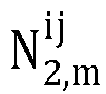


- On a receiving end side, the embodiments of the present application provide a positioning method, including:
- receiving a positioning reference signal sent by a sending end of the positioning reference signal, and the positioning reference signal includes C-PRSs sent by the sending end of the positioning reference signal via at least two carrier frequencies;
- obtaining a positioning measurement value by measuring the positioning reference signal, the positioning measurement value includes a virtual phase measurement value obtained by constructing a carrier phase measurement value obtained by measuring the C-PRSs; and
- sending the positioning measurement value to a positioning server to allow the positioning server to determine a terminal position according to the positioning measurement value.
- On a sending end side, the embodiments of the present application provide a positioning method, including:
- sending configuration information of a positioning reference signal that includes C-PRSs sent via at least two carrier frequencies;
- sending the positioning reference signal to a receiving end of the positioning reference signal to allow the receiving end of the positioning reference signal to obtain a positioning measurement value by measuring the positioning reference signal according to the configuration information, and to send the positioning measurement value to a positioning server to allow the positioning sever to determine a terminal position according to the positioning measurement value, and the positioning measurement value includes a virtual phase measurement value obtained by constructing a carrier phase measurement value obtained by measuring the C-PRSs.
- On the positioning server side, the embodiments of the present application provide a positioning device, including:
- a memory, configured to store program instructions;
- a processor, configured to call the program instructions stored in the memory, and to perform, according to the obtained program:
- determining an integer ambiguity according to a positioning measurement value provided by a receiving end of a positioning reference signal, and the positioning measurement value includes a virtual phase measurement value constructed by the receiving end via utilizing a carrier phase measurement value, the carrier phase measurement value is obtained by measuring C-PRSs by the receiving end, and the positioning reference signal includes C-PRSs sent by a sending end of the positioning reference signal via at least two carrier frequencies; and
- determining a terminal position according to the integer ambiguity.
- Optionally, the processor is configured to:
determine a first integer ambiguity according to the virtual phase measurement value and a TOA measurement value; determine a second integer ambiguity by calculating the first integer ambiguity utilizing an EKF, and determine a third integer ambiguity based on the second integer ambiguity; and determine the terminal position according to the third integer ambiguity. - Optionally, for an m-th base station, a target terminal i and a reference terminal j, when the sending end of the positioning reference signal sends a first C-PRS via a first carrier frequency and sends a second C-PRS via a second carrier frequency, the processor determines the first integer ambiguity


- Optionally, the processor is configured to:
determine a second integer ambiguity


- Optionally, the processor is configured to determine a third
integer ambiguity 
integer ambiguity 


- On the receiving end side, the embodiments of the present application provide a positioning device, including:
- a memory, configured to store program instructions; and
- a processor, configured to call the program instructions stored in the memory, and to perform, according to the obtained program:
- receiving a positioning reference signal sent by a sending end of the positioning reference signal, and the positioning reference signal includes C-PRSs sent by the sending end of the positioning reference signal via at least two carrier frequencies;
- obtaining a positioning measurement value by measuring the positioning reference signal, the positioning reference signal includes a virtual phase measurement value obtained by constructing a carrier phase measurement value obtained by measuring the C-PRSs; and
- sending the positioning measurement value to a positioning server to allow the positioning server to determine a terminal position according to the positioning measurement value.
- On the sending end side, the embodiments of the present application provide a positioning device including:
- a memory, configured to store program instructions;
- a processor, configured to call the program instructions stored in the memory, and to perform, according to the obtained program:
- sending configuration information of a positioning reference signal including C-PRSs sent via at least two carrier frequencies;
- sending the positioning reference signal to a receiving end of the positioning reference signal to allow the receiving end of the positioning reference signal to obtain a positioning measurement value by measuring the positioning reference signal according to the configuration information, and to send the positioning measurement value to a positioning server to allow the positioning sever to determine the a terminal position according to the positioning measurement value, and the positioning measurement value includes a virtual phase measurement value obtained by constructing a carrier phase measurement value obtained by measuring the C-PRSs.
- On the positioning server side, the embodiments of the present application provide another positioning device, including:
- an integer ambiguity determination unit, configured to determine an integer ambiguity according to a positioning measurement value provided by a receiving end of a positioning reference signal, and the positioning measurement value includes a virtual phase measurement value constructed by the receiving end via utilizing a carrier phase measurement value, the carrier phase measurement value is obtained by measuring C-PRSs by the receiving end, and the positioning reference signal includes C-PRSs sent by a sending end of the positioning reference signal via at least two carrier frequencies; and
- a position determination unit, configured to determine a terminal position according to the integer ambiguity.
- On the receiving end side, the embodiments of the present application provide another positioning device, including:
- a receiving unit, configured to receive a positioning reference signal sent by a sending end of the positioning reference signal, and the positioning reference signal includes C-PRSs sent by the sending end of the positioning reference signal via at least two carrier frequencies;
- a positioning measurement unit, configured to obtain a positioning measurement value by measuring the positioning reference signal, the positioning reference signal includes a virtual phase measurement value obtained by constructing a carrier phase measurement value obtained by measuring the C-PRSs; and
- a sending unit, configured to send the positioning measurement value to a positioning server to allow the positioning server to determine a terminal position according to the positioning measurement value.
- On the sending end side, the embodiments of the present application provide another positioning device, including:
- a first sending unit, configured to send configuration information of a positioning reference signal that includes C-PRSs sent via at least two carrier frequencies; and
- a second sending unit, configured to send the positioning reference signal to a receiving end of the positioning reference signal to allow the receiving end of the positioning reference signal to obtain a positioning measurement value by measuring the positioning reference signal according to the configuration information, and to send the positioning measurement value to a positioning server to allow the positioning server to determine a terminal position according to the positioning measurement value, and the positioning measurement value includes a virtual phase measurement value obtained by constructing a carrier phase measurement value obtained by measuring the C-PRSs.
- The embodiments of the present application provide a computing device, including a memory configured to store program instructions, and a processor configured to call the program instructions stored in the memory to perform any one of the above methods in accordance with the obtained program.
- The embodiments of the present application provide a computer storage medium, and the computer storage medium stores computer executable instructions that are configured to cause a computer to perform any one of the above methods.
- In order to more clearly illustrate the technical solutions in the embodiments of the present application, the drawings required to be used in the description of the embodiments will now be briefly introduced. Obviously, the drawings in the following description are merely some embodiments of the present application, and those of ordinary skill in the art can obtain other drawings from these drawings without creative work.
-
FIG. 1 is a schematic diagram of C-PRSs in two cases in accordance with an embodiment of the present application. -
FIG. 2 is a flowchart illustrating a positioning procedure of a method for quickly searching an integer ambiguity for carrier phase positioning in accordance with an embodiment of the present application. -
FIG. 3 is a flowchart illustrating a positioning method on a positioning server side according to an embodiment of the present application. -
FIG. 4 is a flow chart illustrating a positioning method on a receiving end side according to an embodiment of the present application. -
FIG. 5 is a flowchart illustrating a positioning method on a sending end side according to an embodiment of the present application. -
FIG. 6 is a schematic structural diagram illustrating a positioning device according to an embodiment of the present application. -
FIG. 7 is a schematic structural diagram illustrating a positioning device on a positioning server side according to an embodiment of the present application. -
FIG. 8 is a schematic structural diagram illustrating a positioning device on a receiving end side according to an embodiment of the present application. -
FIG. 9 is a schematic structural diagram illustrating a positioning device on a receiving end side according to an embodiment of the present application. - The technical solutions in embodiments of the present application will now be clearly and completely described in combination with the drawings in the embodiments of the present application. Obviously, the described embodiments are only some, but not all, embodiments of the present application. Based on the embodiments in the present application, all other embodiments obtained by those of ordinary skill in the art without creative work fall within the scope of protection of the present application.
- Embodiments of the present application provide a UE positioning method based on a carrier signal phase measurement value of a 3GPP radio communication system itself, in view of the problem of low positioning accuracy of the current 3GPP defined method for determining the position of the UE by measuring reference signals of the wireless communication system itself. In such a method, a sending end (e.g. a base station (BS) or a UE or a vehicle) for a signal in a 3GPP wireless communication system sends not only PRS but also Carrier Phase Positioning Reference Signal (C-PRS) for carrier phase positioning. The receiving end receives PRS and C-PRS to obtain a positioning measurement value including Time of Arrival (TOA)/Time Difference of Arrival (TDOA) and a carrier phase measurement value. This method utilizes the 3GPP wireless communication system itself to send a positioning reference signal and a carrier reference signal to perform positioning and can work when Global Navigation Satellite System (GNSS) has weak satellite signals or cannot receive signals, to determine the position of the UE with high accuracy.
- To facilitate description, a positioning reference signal PRS as described in the embodiment herein represents all reference signals that can be used for measuring TOA, e.g. the PRS includes PRS, CSI-RS, Channel Sounding Reference Signal (SRS), or the like that can be used for traditional OTDOA/UTDOA positioning.
- An Extended Kalman Filter (EKF) is an efficient recursive filter that can perform optimal estimation on a target state under non-linear model conditions. EKF algorithms are commonly applied in the positioning field. In the positioning of the GNSS, the EKF algorithms are widely used to estimate an integer ambiguity and a variance of the integer ambiguity. EKF-based integer ambiguity estimation is commonly used in the field of satellite positioning. However, existing EKF solutions use only single-frequency-point carrier phase measurement values, and the EKF algorithms cannot accurately estimate the integer ambiguity in scenarios of high moving speed of a user and high measurement noise. Based on this, the embodiments of the present application provide a method of combining multiple carrier frequencies (sub-carrier frequencies) into virtual carriers, which is applied to the EKF algorithms to further improve the stability and accuracy of the EKF algorithms.
- The integer ambiguity is an important unknown parameter for positioning utilizing a carrier phase technology, and the embodiments of the present application can solve this parameter quickly and accurately, followed by determination of the user position. For example:


- A basic UE positioning method based on wireless communication carrier phase measurement includes the following steps.
- A sending end (BS or UE) sends a PRS and a C-PRS at preconfigured or predefined carrier frequencies. The C-PRS may generally be a sinusoidal carrier signal or may also be different subcarriers of one carrier.
- For a downlink positioning method, for example, the BS is the sending end for OTDOA. Each BS sends the PRS and the C-PRS at the preconfigured or predefined carrier frequencies. Neighboring different cells may send the C-PRS at different subcarriers.
- For an uplink positioning methods, for example, the UE is the sending end for UTDOA. The UE also sends the PRS and the C-PRS at the preconfigured or predefined carrier frequencies. Different UEs may send the C-PRS at different subcarriers.
- A receiving end (BS or UE) may measure the PRS and the C-PRS according to configuration information of the PRS and the C-PRS; a positioning measurement value measured by the PRS may include TOA/TDOA (wherein TDOA is also referred to as Reference Signal Time Difference (RSTD)), or the like; and a carrier phase measurement value (CP) measured by the C-PRS.
- The receiving end (BS or UE) reports a positioning measurement value (TOA/TDOA/CP, etc.,) to a certain positioning server in the wireless communication system. The positioning server determines the position of the UE with high accuracy according to the configuration information of the PRS and the C-PRS, such as the position of a transmit antenna of each cell, and the positioning measurement value provided by the receiving end.
- There may be several basic approaches to use the TOA and the phase measurement value for positioning as follows.
- A non-differential approach: the position of the UE is calculated directly utilizing the TOA and the phase measurement value without using a differential technology.
- A differential approach: firstly, difference is performed on the TOA and the phase measurement value to remove some common offsets in the measurement value, and then, the position of the UE is calculated by the TOA and phase measurement value subjected to difference. The difference approach includes a single-difference approach and a double-difference approach.
- The single-difference approach: a sending end (or receiving end) is selected as a reference end, and then difference is performed on a measurement value relevant to another sending end (or receiving end) and a measurement value relevant to the reference end. The objective of the single difference is to eliminate measurement deviation at an end (receiving end or sending end). For example, an RSTD measurement value for OTDOA positioning is obtained by performing difference on a TOA measurement value relevant to each BS and TOA measurement values relevant to the UE and a reference BS, and the objective of the difference is to cancel the impact of UE clock offset on positioning.
- The double-difference approach: difference is performed on the measurement value subjected to single difference again to simultaneously eliminate measurement errors relevant to the sending end and the receiving end, such as clock offsets of the BS and the UE. For example, the double-difference technology may be used in a downlink positioning scenario. At this point, there are sending ends (base stations) and two receiving ends, and one of the two receiving ends is a reference end with a known position. The other receiving end is a UE with an unknown position. At the moment, the two receiving ends simultaneously receive positioning signals sent by the base stations, the double-difference technology is used to remove common errors, relevant to the sending end and the receiving end, in the measurement values of the two receiving ends, and then the position of the receiving end with the unknown position is accurately calculated.
- However, there are two main drawbacks in the carrier phase based terminal position solving algorithm:
- first, by linear combination, the measurement noise of the virtual carrier is loud, and if a wrong integer ambiguity is searched by the integer ambiguity, a great impact may be brought to positioning; and
- second, when a single frequency point is used for integer ambiguity estimation, the integer ambiguity appears numerically large due to the shorter wavelength, making it difficult for the EKF algorithm to converge to the correct integer ambiguity, resulting in failure of the algorithm.
- Accordingly, the embodiments of the present application provide a multi-carrier frequency EKF terminal position positioning method and device. With a combination of multiple carrier frequencies, a greater virtual wavelength is constructed and the EKF algorithm is used for integer ambiguity estimation. After the estimation is completed, an integer ambiguity of an actual carrier phase is obtained by conversion, thereby improving the positioning accuracy. That is, the problem of failure of convergence of the EKF due to smaller wavelengths is avoided, and the problem of large errors caused by direct estimation on the integer ambiguity by virtual wavelengths is also solved.
- The method and the device are based on the same application conception, the implementations of the device and the method can be referred to each other due to the similar principles of the method and the device for solving the problems, and repetition parts will not be described.
- The technical solutions provided by the embodiments of the present application may be applicable to a variety of systems, in particular 5G systems. For example, an applicable system may be a Global System of Mobile Communication (GSM) system, a Code Division Multiple Access (CDMA) system, a Wideband Code Division Multiple Access (WCDMA) General Packet Radio Service (GPRS) system, a Long Term Evolution (LTE) system, an LTE Frequency Division Duplex (FDD) system, an LTE Time Division Duplex (TDD) system, a Universal Mobile Telecommunication System (UMTS), a Worldwide Interoperability for Microwave Access (WiMAX) system, a 5G system, a 5G NR system, and the like. These systems include terminal devices and network devices.
- The embodiments of the present application relate to a terminal device, which may be a device providing voice and/or data connectivity to a user, a handheld device with a wireless connection function, or other processing devices connected to a wireless modem. In different systems, the names of the terminal devices may also not be the same, for example in a 5G system, the terminal device may be referred to as UE. A wireless terminal device may be communication with one or more core networks via a Radio Access Network (RAN). The wireless terminal device may be a mobile terminal device such as a mobile phone (or referred to as "cellular" phone) and a computer with the mobile terminal device, such as portable, pocket-size, hand-held, computer-built or vehicle-mounted mobile devices, which exchange language and/or data with the RAN, such as a Personal Communication Service (PCS) phone, a cordless phone, a Session Initiated Protocol (SIP) phone, a Wireless Local Loop (WLL) station, a Personal Digital Assistant (PDA), or other devices. A wireless end device may also be referred to as a system, a subscriber unit, a subscriber station, a mobile station, a mobile, a remote station, an access point, a remote terminal, an access terminal, a user terminal, a user agent, a user device, which is not limited in the embodiments of the present application.
- The embodiments of the present application relate to a network device, which may be a base station that may include cells. The base station may also be referred to as an access point, or may refer to a device that is in communication with a wireless terminal device by one or more sectors over an air interface in an access network, or may be referred to as other names, depending on the particular application occasions. The network device may be configured to interconvert received air frames and internet protocol (IP) packets as a router between the wireless terminal device and the remainder of the access network, and the remainder of the access network may include an IP communication network. The network device may also coordinate property management for the air interface. For example, the network device according to the embodiments of the present application may be a network device (base transceiver station, BTS) in a GSM or CDMA, may also be a network device in NodeB in WCDMA, an evolutional node B (eNB or e-NodeB) in an LTE system, a 5G base station in a 5G network architecture (next generation system), a home evolved node B (HeNB), a relay node, femto, a pico, or the like, which is not limited in the embodiments of the present application.
- Various embodiments of the present application are described in detail below with reference to the drawings. It should be noted that the presence order of the embodiments of the present application is merely representative of a sequential order of the embodiments and does not represent the advantage and disadvantage of the technical solutions provided by the embodiments.
- In the technical solutions provided by the embodiments of the present application, a sending end sends two (or more) C-PRSs at different frequencies, a receiving end constructs a virtual phase measurement value based on the two (or more) carrier phase measurement values, and a positioning server performs multi-cycle position tracking on a terminal via an EKF, so that a virtual integer ambiguity of the virtual phase value is quickly searched out, further, an actual integer ambiguity and an actual phase measurement value are calculated, and finally, a UE position is calculated.
- The C-PRSs at different frequencies may be on different carriers or different subcarriers of the same carrier. For example, in a FDD mode, the C-PRSs may also be sent by the first and last Resource Elements (REs) of a carrier with a bandwidth (BW)=100 MHz, or PRSs of the first RE and the last RE of the carrier with BW=100 MHz serve as the C-PRSs.
- As shown in
FIG. 1 , CASE1 represents a case where, different subcarriers of the same carrier are selected as the C-PRSs. CASE2 represents a case where carriers with different frequencies are selected as C-PRSs. - The specific solution is summarized as follows.
- For the sending end, two or more carrier frequencies are configured to send C-PRSs (or different sub-carriers of the same carrier as C-PRS) by utilizing the feature that the 3GPP wireless communication system can configure C-PRSs sent by itself.
- For the receiving end, a virtual phase measurement value with a very long virtual wavelength is constructed by utilizing carrier phase measurement values measured by the C-PRSs sent via two (or more) carrier frequencies; and for an Orthogonal Frequency Division Multiplexing (OFDM) system, in the FDD mode, two (or more) subcarriers at different positions are selected for virtual wavelength construction.
- For a positioning server side.
- First, further calculation is performed based on the virtual wavelength and virtual phase measurement value reported by the receiving end; with the feature of the very long virtual wavelength of the virtual phase measurement value, the search space for the virtual integer ambiguity is greatly reduced; a virtual integer ambiguity (which may be referred to as a first integer ambiguity) is searched quickly with TOA and the virtual phase measurement value.
- Second, the virtual phase measurement value reported by the receiving end, as well as the quickly searched virtual integer ambiguity, are input to an EKF algorithm module, and finally a virtual integer ambiguity (which may be referred to as a second integer ambiguity) is output.
- Third, an actual integer ambiguity (which may be referred to as a third integer ambiguity) is calculated with the final output virtual integer ambiguity (i.e., the second integer ambiguity); and the UE position is then calculated by utilizing the actual integer ambiguity and an actual phase measurement value.
- For the actual phase measurement value, for example:


- The method for quickly determining the integer ambiguity provided by the embodiments of the present application may be applicable to the above various "non-difference", "single-difference", and "double-difference" approaches. Since the EKF algorithm uses the single-difference carrier phase measurement value to calculate the integer ambiguity, the embodiments of the present application are described with single difference as an example.
- In one embodiment, assuming that C-PRSs are sent via two carrier frequencies, a first carrier sends a first C-PRS and a second carrier sends a second C-PRS, the method for quickly searching carrier phase for positioning by single difference includes the following steps.
- Step 1: the receiving end obtains a single-difference TOA measurement value and a phase single-difference measurement value.
- Taking an m-th base station as an example, single difference on a target UE i and a reference UE j is taken as an example, after single-difference calculation, a TOA measurement value (also referred to as TDOA) and a phase single-difference measurement value are calculation as:


- Where,


- The superscript "ij" denotes that the single difference operation is performed relatively between measurement values of two receiving ends i and j, and the subscript denotes the m-th base station that sends the positioning reference signals, i.e.,

- If it is assumed that the BS is the sending end and the UE is the receiving end, the clock offset of the base station in the single-difference manner is eliminated.
- A reference receiving end (reference UE): one (or more) reference UEs receive wireless reference signals sent by the base station to obtain TOA and a carrier phase reference measurement value. TOA and a carrier phase reference measurement value measured by the reference UE and TOA and a carrier phase measurement value measured by the target UE constitute a difference measurement value for carrier phase positioning. The position of a receiving antenna of the reference UE is known.
- A target UE receiving end (target UE): the target UE also receives the wireless reference signals sent by the base station and obtains TOA and a carrier phase measurement value. The TOA and the carrier phase measurement value measured by the target UE and the TOA and the carrier phase reference measurement value measured by the reference UE constitute a difference measurement value for carrier phase positioning to determine a target UE position to be solved.
- Step 2: the receiving end constructs a virtual single-difference phase measurement value with a longer virtual wavelength.
- Two sides of the equal signs of the above equations (2) and (3) are multiplied by λ2/(λ2 -λ1) and -λ1/(λ2 - λ1), respectively, and then the results are added together, and likewise form a virtual single-difference phase measurement value


- Where, λv, Nv,m and wv,m represent the carrier virtual wavelength, the virtual integer ambiguity, and the virtual phase measurement error, respectively, and there may be:



- Step 3: a positioning server quickly calculates a virtual integer ambiguity Nv (i.e., an integer ambiguity calculated for the first time, a first integer ambiguity for short).
- Accordingly,


- In the embodiments of the present application, when C-PRS sending frequencies f1 and f2 are selected, factors required to be considered are:
when the C-PRS sending frequencies f1 and f2 are selected, the virtual wavelength λv and the virtual measurement error

measurement errors 


- Step 4: the positioning server determines an integer ambiguity based on virtual and actual phase measurement values, which includes steps 4a and 4b below.
- Step 4a: the positioning server uses the virtual phase measurement value to determine a virtual integer ambiguity (i.e., an integer ambiguity calculated for the second time, a second integer ambiguity for short).
- After


- 1. An initial state vector is changed:
an existing EKF state vector is:
- Where:
- δr = (δx, δy, δz)T is a 3D UE position error;
- δv = (δvx, δvy, δvz)T is a 3D UE speed error;
-

- If only 2D positioning is considered, the EKF state vector x will not include δZ and δvz .
- The position error δr of the UE is defined as:

- The UE speed error δv is defined as:

- The EKF state vector in the embodiments of the present application is:


- 2. The wavelength λ in the EKF algorithm is replaced with the virtual wavelength λv.
- 3. An initialized covariance matrix is modified.
- An existing initialized covariance matrix is:


- The updated covariance matrix in the embodiments of the present application is:

- For

- 4. A measurement noise matrix R.
- An existing measurement noise matrix is


- Where E[wy] = 0; RT and RL denote the covariance matrices of measurement noise wT and measurement noise wL, respectively.



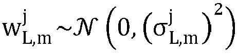
- Where,



- The measurement noise matrix of the noise in the embodiments of the present application is:


- Where E[wy] = 0; RT and





- Where


- The calculation is performed by the EKF algorithm to obtain the virtual integer ambiguity (i.e., the second integer ambiguity)

- Step 4b: The positioning server calculates the integer ambiguity of an actual phase (i.e., an integer ambiguity calculated for the third time, a third integer ambiguity for short).
- Taking the virtual carrier phase ambiguity


- The equation (7) denotes that after



- Step 5: the positioning server uses the integer ambiguity of the actual phase (i.e., the third integer ambiguity) for positioning.
- The
above step 4 is repeated. By taking the sending frequency f1 as an example, a series ofinteger ambiguities 
step 4, and in combination with the phasemeasurement values 
- For example,
FIG. 2 shows a positioning procedure according to the embodiments of the present application applying a fast search carrier phase positioning integer ambiguity method, including the following steps. -
Step 1, the sending end (BS or UE), in addition to being configured to send a conventional PRS, is configured to send C-PRSs for carrier phase positioning at two or more carrier frequencies according to the requirements of the embodiments of the present application; in the FDD mode, the C-PRSs may also be sent with, for example, a first RE and a last RE of a carrier with BW=100 MHz; the sending end (BS or UE) informs the positioning server of the configuration information of PRSs and C-PRSs. - For a downlink reference signal-based UE positioning method, such as OTDOA, the BS is the sending end.
- For an uplink reference signal-based UE positioning method, such as UTDOA, the UE is the sending end.
- The selection of the C-PRS sending frequency should take into account both the virtual wavelength and the virtual measurement error; to efficiently use the virtual phase measurement value to search for the virtual integer ambiguity, the virtual measurement error needs to be smaller than the TOA measurement error by an order of magnitude; with this condition satisfied, the virtual wavelength may be increased to the greatest extent to reduce the search space for the virtual integer ambiguity.
-
Step 2, the positioning server informs the receiving end (BS or UE) of the PRSs and C-PRSs of configuration information of the PRSs and the C-PRSs. -
Step 3, the sending end (BS or UE) sends the PRSs and the C-PRSs according to the configuration information of the PRSs and the C-PRSs. The C-PRSs are sent at two or more carrier frequencies. -
Step 4, the receiving end receives the PRSs and the C-PRSs according to the configuration information of the PRSs and the C-PRSs, to obtain TOA and the carrier phase measurement value. -
Step 5, the receiving end reports the positioning measurement values obtained by measuring the PRSs and C-PRSs to the positioning server; if the receiving end is a UE, the positioning measurement values reported by the receiving end may be TOA and the carrier phase measurement value without difference, or may be TDOA subjected to single difference and a single-difference carrier phase measurement value. -
Step 6 and step 7: first the positioning server rapidly searches for the integer ambiguity by utilizing the method provided by the embodiments of the present application and then performs UE positioning. - If the single-difference manner is used, the integer ambiguity is determined by utilizing the above fast search single-difference manner, which includes the following steps:
- the single-differenced phase measurement value measured by the C-PRSs sent via two or more carrier (or a plurality of sub-carriers) frequencies are used to construct a virtual single-difference phase measurement value (as shown in equation (5));
- the TDOA measurement value and the virtual single-difference phase measurement value are used to determine a virtual integer ambiguity search space to search for a virtual integer ambiguity (equation (6)); and
- the virtual integer ambiguity is tracked by utilizing the EKF algorithm to finally output the virtual integer ambiguity; the virtual integer ambiguity is utilized to continue to search for the actual integer ambiguity (equation (7)); and the UE position is then calculated by utilizing the actual integer ambiguity and the actual phase measurement value.
- The above embodiments only describes a process of positioning a user in one positioning cycle and, similarly, may be applied in practice for multiple positioning cycles for tracking of the motion trajectory of the user. Due to the characteristics of the EKF algorithm, multiple-cycle trajectory tracking of the user is performed, which more contributes to accurately determine the integer ambiguity, to improve the positioning accuracy.
- In summary, in the technical solution provided by the embodiments of the present application, an EKF utilizes the characteristic of a very long virtual wavelength of the virtual phase measurement value to track the virtual integer ambiguity for multiple measurement cycles by the TOA and the virtual phase measurement value, to determine the virtual integer ambiguity quickly and accurately. By utilizing the virtual integer ambiguity, the actual integer ambiguity is quickly searched. The UE position is then calculated by utilizing the actual integer ambiguity and the actual phase measurement value.
- Since the virtual wavelength of the virtual phase measurement value "constructed" by the embodiments of the present application can be one order of magnitude larger than the actual wavelength, the stability of the integer ambiguity estimation by utilizing the EKF algorithm is improved, and the problem that the EKF cannot accurately search for the integer ambiguity due to the shorter wavelength is avoided.
- After the integer ambiguity estimation is performed by the EKF, in the embodiments of the present application, the positioning is performed by a manner of inverse calculation on the integer ambiguity of the virtual carrier back into the single carrier, thereby greatly reducing the positioning error and avoiding the problem of increasing the measurement error when the virtual carrier is constituted.
- Referring to
FIG. 3 , the embodiments of the present application provide a positioning method on a positioning server side, including the following steps. - S301, determining an integer ambiguity according to a positioning measurement value provided by a receiving end of a positioning reference signal, and the positioning measurement value includes a virtual phase measurement value constructed by the receiving end via utilizing a carrier phase measurement value, the carrier phase measurement value is obtained by measuring C-PRSs by the receiving end, and the positioning reference signal includes C-PRSs sent by a sending end of the positioning reference signal via at least two carrier frequencies.
- S302, determining a terminal position according to the integer ambiguity.
- Optionally, determining the integer ambiguity according to the positioning measurement value provided by the receiving end of the positioning reference signal includes: determining a first integer ambiguity (i.e., a virtual phase measurement value searched quickly) according to the virtual phase measurement value and a TOA measurement value; determining a second integer ambiguity (i.e., a virtual phase measurement value output by the EKF) by calculating the first integer ambiguity utilizing an EKF, and determining a third integer ambiguity (i.e., an actual phase measurement value) based on the second integer ambiguity; and determining the terminal position by the third integer ambiguity.
- Optionally, for an m-th base station, a target terminal i and a reference terminal j, when the sending end of the positioning reference signal sends a first C-PRS via a first carrier frequency and a second C-PRS via a second carrier frequency, the first integer ambiguity


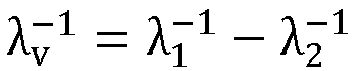


- The first carrier is a carrier for sending the first C-PRS; the second carrier is a carrier for sending the second C-PRS; and the first carrier and the second carrier are different in frequency.
- Optionally, parameters


- Optionally, a third
integer ambiguity 
integer ambiguity 


- Referring to
FIG. 4 , the embodiments of the present application provide a positioning method on a receiving end side, including: - S401, receiving a positioning reference signal sent by a sending end of a positioning reference signal, and the positioning reference signal includes C-PRSs sent by the sending end of the positioning reference signal via at least two carrier frequencies;
- S402, obtaining a positioning measurement value by measuring the positioning reference signal, the positioning measurement value includes a virtual phase measurement value obtained by constructing a carrier phase measurement value obtained by measuring the C-PRSs; and
- S403, sending the positioning measurement value to a positioning server to allow the positioning server to determine a terminal position according to the positioning measurement value.
- Referring to
FIG. 5 , the embodiments of the present application provide a positioning method on a sending end side, including: - S501, sending configuration information of a positioning reference signal that includes C-PRSs sent via at least two carrier frequencies; and
- S502, sending the positioning reference signal to a receiving end of the positioning reference signal to allow the receiving end of the positioning reference signal to obtain a positioning measurement value by measuring the positioning reference signal according to the configuration information and to send the positioning measurement value to a positioning server to allow the positioning server to determine a terminal position according to the positioning measurement value, and the positioning measurement value includes a virtual phase measurement value obtained by constructing a carrier phase measurement value obtained by measuring the C-PRSs.
- Referring to
FIG. 6 , the embodiments of the present application provide a positioning device, including amemory 620 and aprocessor 600, and thememory 620 is configured to store program instructions, and atransceiver 610 configured to receive and transmit data under control of theprocessor 600 configured to call the program instructions stored in thememory 620 to perform any of the positioning methods described above according to the obtained program. - The
transceiver 610 is configured to receive and transmit data under control of theprocessor 600. - In
FIG. 6 , a bus architecture may include any number of interconnected buses and bridges, and various circuits of one or more processors, represented by theprocessor 600, and memories, represented by thememory 620 are linked together. The bus architecture may also link various other circuits such as peripherals, voltage regulators, power management circuits, and the like, which are well known in the art, and therefore, will not be described any further herein. The bus interface provides an interface. Thetransceiver 610 may be a plurality of elements, that is, includes a sending end and a receiving end, and provides a unit for communicating with various other devices over a sending medium. Theprocessor 600 is responsible for managing the bus architecture and general processing, and thememory 620 can store data used by theprocessor 600 when performing operations. - The
processor 600 may be a central processing unit (CPU), an Application Specific Integrated Circuit (ASIC), a Field-Programmable Gate Array (FPGA), or a Complex Programmable Logic Device (CPLD). - If the positioning device is a user device, the positioning device may also include a user interface connected to the bus architecture, which may also be an interface for external and internal connection of required devices including but not limited to a keypad, a display, a speaker, a microphone, a joystick and the like.
- Particularly, if the positioning device serves as a device on the positioning server side (which can also be the positioning server itself), the
processor 600 is configured to call program instructions stored in the memory to perform, according to the obtained program:
determining an integer ambiguity according to a positioning measurement value provided by a receiving end of a positioning reference signal, and the positioning measurement value includes a virtual phase measurement value constructed by the receiving end via utilizing a carrier phase measurement value, the carrier phase measurement value is obtained by measuring a C-PRS by the receiving end, and the positioning reference signal includes C-PRSs sent by a sending end of the positioning reference signal via at least two carrier frequencies; and determining a terminal position according to the integer ambiguity. - Optionally, the
processor 600 is configured to: determine a first integer ambiguity according to the constructed virtual phase measurement value and a TOA measurement value; determine a second integer ambiguity by calculating the first integer ambiguity utilizing an EKF, and determine a third integer ambiguity based on the second integer ambiguity; and determine a terminal position by the third integer ambiguity. - Optionally, for the m-th base station, target terminal i and reference terminal j, when the sending end of the positioning reference signal transmits a first C-PRS over a first carrier frequency and a second C-PRS over a second carrier frequency, the
processor 600 is configured to determine the first integer ambiguity

- Where for


- Optionally, the
processor 600 is configured to:
determine a second integer ambiguity


- Optionally, the
processor 600 is configured to determine a thirdinteger ambiguity 
integer ambiguity 


- If the positioning device serves as a device on the receiving end side (the receiving end itself, the receiving end being either a base station or a terminal), the
processor 600 is configured to call program instructions stored in the memory to perform in according with the obtained program: - receiving a positioning reference signal sent by a sending end of a positioning reference signal, the positioning reference signal includes C-PRSs sent by the sending end of the positioning reference signal via at least two carrier frequencies;
- obtaining a positioning measurement value by measuring the positioning reference signal, the positioning reference signal includes a virtual phase measurement value obtained by constructing a carrier phase measurement value obtained by measuring the C-PRSs; and
- sending the positioning measurement value to a positioning server to allow the positioning server to determine a terminal position according to the positioning measurement value.
- If the positioning device serves as a device on the sending end side (the sending end itself, the sending end being either a base station or a terminal), the
processor 600 is configured to call program instructions stored in the memory to perform according to the obtained program: - sending configuration information of a positioning reference signal including C-PRSs sent via at least two carrier frequencies; and
- sending the positioning reference signal to a receiving end of the positioning reference signal to allow the receiving end of the positioning reference signal to obtain a positioning measurement value by measuring the positioning reference signal according to the configuration information, and to sending the positioning measurement value to a positioning server to allow the positioning sever to determine the a terminal position according to the positioning measurement value, and the positioning measurement value includes a virtual phase measurement value obtained by constructing a carrier phase measurement value obtained by measuring the C-PRSs.
- Referring to
FIG. 7 , the embodiments of the present application provide another positioning device on the positioning server side, including: - an integer
ambiguity determination unit 71, configured to determine an integer ambiguity by a positioning measurement value provided by a receiving end of a positioning reference signal, and the positioning measurement value includes a virtual phase measurement value constructed by the receiving end via utilizing a carrier phase measurement value, the carrier phase measurement value is obtained by measuring a C-PRS by the receiving end, and the positioning reference signal includes C-PRSs sent by a sending end of the positioning reference signal via at least two carrier frequencies; - a
position determination unit 72, configured to determine a terminal position according to the integer ambiguity. - Optionally, the integer
ambiguity determination unit 71 is configured to:
determine a first integer ambiguity by the virtual phase measurement value and a TOA measurement value; determine a second integer ambiguity by calculating the first integer ambiguity utilizing an EKF, and determine a third integer ambiguity based on the second integer ambiguity; and determine a terminal position according to the third integer ambiguity. - Optionally, for an m-th base station, a target terminal i and a reference terminal j, when the sending end of the positioning reference signal sends a first C-PRS via a first carrier frequency and a second C-PRS via a second carrier frequency, the integer
ambiguity determination unit 71 is configured for:
- Where for


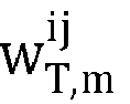


- Optionally, the integer
ambiguity determination unit 71 is configured to:
determine a second integer ambiguity


- Optionally, the integer
ambiguity determination unit 71 is configured to a thirdinteger ambiguity 
integer ambiguity 


- Referring to
FIG. 8 , the embodiments of the present application provide another positioning device on the receiving end side, including: - a receiving
unit 81, configured to receive a positioning reference signal sent by a sending end of the positioning reference signal, and the positioning reference signal includes C-PRSs sent by the sending end of the positioning reference signal via at least two carrier frequencies; - a
positioning measurement unit 82, configured to obtain a positioning measurement value by measuring the positioning reference signal, the positioning measurement value includes a virtual phase measurement value obtained by constructing a carrier phase measurement value obtained by measuring the C-PRSs; - a sending
unit 83, configured to send the positioning measurement value to a positioning server to allow the positioning server to determine a terminal position according to the positioning measurement value. - Referring to
FIG. 9 , the embodiments of the present application provide another positioning device on the receiving end side, including: - a first sending
unit 91, configured to send configuration information of a positioning reference signal including C-PRSs sent via at least two carrier frequencies; and - a
second sending unit 92, configured to send the positioning reference signal to a receiving end of the positioning reference signal to allow the receiving end of the positioning reference signal to obtain a positioning measurement value by measuring the positioning reference signal according to the configuration information, and to send the positioning measurement value to a positioning server to allow the positioning server to determine a terminal position according to with the positioning measurement value, and the positioning measurement value includes a virtual phase measurement value obtained by constructing a carrier phase measurement value obtained by measuring the C-PRSs. - It should be noted that the division of units in the embodiments of the present application is illustrative and is a logical functional division, and that other divisions may be implemented in practice. Furthermore, functional units in the various embodiments of the present application may be integrated in one processing unit, or may exist separately, or two or more units may also be integrated into one unit. The above integrated units may be implemented in the form of hardware or software functional units.
- The integrated unit, if implemented in the form of a software functional unit and sold or used as an independent product, may be stored in one computer-readable storage medium. Based on such understanding, the embodiments of the present application essentially or a part of the solution contributing to the prior art, or all or a part of the solution, may be embodied in the form of a software product, the computer software product is stored in a storage medium and includes instructions for causing a computer device (which may be a personal computer, a server, a network device, or the like) or a processor to perform all or part of the steps of the methods described in various embodiments of the present application. The foregoing storage media includes various media which may store program code, such as a USB disk, a mobile hard disk, a Read-Only Memory (ROM), a Random Access Memory (RAM), a magnetic disk or an optical disk.
- The embodiments of the present application provide a computing device, which may be a desktop computer, a portable computer, a smartphone, a tablet computer, a Personal Digital Assistant (PDA), or the like. The computing device may include a Central Processing Unit (CPU), a memory, and input/output devices, the input device may include a keyboard, a mouse, a touch screen, etc., and the output device may include display devices such as a Liquid Crystal display (LCD), a Cathode Ray Tube (CRT), etc.
- The memory may include ROM and RAM and provide the processor with program instructions and data stored in the memory. In the embodiments of the present application, the memory may be configured to store programs for any of the methods provided by the embodiments of the present application.
- The processor, by calling the program instructions stored in the memory, is configured to perform any of the methods provided by the embodiments of the present application in accordance with the obtained program instructions.
- The embodiments of the present application provide a computer storage medium configured to store computer program instructions used for the device provided by the embodiments of the present application, including a program configured to perform any of the methods provided by the above embodiments of the present application.
- The computer storage medium can be any available medium or data storage device that can be accessed by a computer, including but not limited to a magnetic memory (e.g., a floppy disk, a hard disk, a magnetic tape, a magnetooptical disks (MO), or the like), an optical memory (e.g., CD, DVD, BD, HVD, or the like), and a semiconductor memory (e.g., ROM, EPROM, EEPROM, NAND FLASH, a Solid State Disk (SSD)), etc.
- The methods provided by the embodiments of the present application can be applied to a terminal device, or may also be applied to a network device.
- A terminal device may also be referred to as "UE", a mobile station ("MS" for short), a mobile terminal, or the like. Optionally, the terminal may communicate via a RAN with one or more core networks, for example, the terminal may be a mobile phone (or referred to as "cellular" phone), or a computer having a mobile property or the like, e.g., the terminal may also be a portable, pocket-size, hand-held, computer-built or vehicle-mounted mobile device.
- A network device may be a base station (e.g., an access point), which may refer to a device that is in communication with a wireless terminal device by one or more sectors over an air interface in an access network. The base station may be configured to interconvert received air frames and internet protocol (IP) packets as a router between the wireless terminal device and the remainder of the access network, and the remainder of the access network may include an IP communication network. The base station may also coordinate property management for the air interface. For example, the base station may be a base transceiver station (BTS) in a GSM or CDMA, may also be a base station (NodeB) in WCDMA, an evolutional base station (NodeB or eNB or e-NodeB) in an LTE system, or may also be gNB in a 5G system.
- The processing flows of the above method may be implemented in a software program, which may be stored in a storage medium, and when the stored software program is called, the above method steps are performed.
- Those skilled in the art should understand that the embodiments of the present application may be provided as a method, system, or computer program product. Accordingly, the present application may take the form of an entirely hardware embodiment, an entirely software embodiment or an embodiment combining software and hardware aspects. Furthermore, the present application may take the form of a computer program product implemented on one or more computer usable storage media (including but not limited to a magnetic disk memory, an optical memory, and the like) containing computer usable program codes.
- The present application is described with reference to flowcharts and/or block diagrams of methods, devices (systems) and computer program products in accordance with the embodiments of the present application. It should be understood that each flow and/or block in the flowcharts and/or block diagrams, and combinations of the flows and/or blocks in the flowcharts and/or block diagrams, can be implemented by the computer program instructions. These computer program instructions may be provided to a general purpose computer, a special-purpose computer, an embedded processor, or a processor of other programmable data processing device to produce a machine, and the instructions, which are executed via the processor of the computer or other programmable data processing devices, are configured to implement the functions specified in one or more flows in the flowcharts and/or one or more blocks in the block diagrams.
- These computer program instructions may also be stored in a computer-readable memory that can direct the computer or other programmable data processing device to work in a particular manner, and the instructions stored in the computer-readable memory are caused to produce an article of manufacture including an instruction device which implement the functions specified in one or more flows in the flowcharts and/or one or more blocks in the block diagrams.
- These computer program instructions may also be loaded onto a computer or other programmable data processing device, and a series of operational steps are performed on the computer or other programmable device to produce a computer-implemented process, and thus, the instructions which are executed on the computer or other programmable device provide steps for implementing the functions specified in one or more flows in the flowcharts and/or one or more blocks in the block diagrams.
- Obviously, those skilled in the art may perform various modifications and variations on the present application without departing from the spirit and scope of the present application. Thus, it is intended that the present application include such modifications and variations if these modifications and variations come within the scope of the appended claims and their equivalents.
Claims (18)
- A positioning method, comprising:determining an integer ambiguity according to a positioning measurement value provided by a receiving end of a positioning reference signal, wherein the positioning measurement value comprises a virtual phase measurement value constructed by the receiving end via utilizing a carrier phase measurement value, the carrier phase measurement value is obtained by measuring Carrier Phase Positioning Reference Signals, C-PRSs, by the receiving end, and the positioning reference signal comprises C-PRSs sent by a sending end of the positioning reference signal via at least two carrier frequencies; anddetermining a terminal position according to the integer ambiguity.
- The method according to claim 1, wherein determining the integer ambiguity according to the positioning measurement value provided by the receiving end of the positioning reference signal comprises:determining a first integer ambiguity according to the virtual phase measurement value and a Time of Arrival, TOA, measurement value;determining a second integer ambiguity by calculating the first integer ambiguity utilizing an Extended Kalman Filter, EKF, and determining a third integer ambiguity based on the second integer ambiguity; anddetermining the terminal position according to the third integer ambiguity.
- The method according to claim 2, wherein for an m-th base station, a target terminal i and a reference terminal j, when the sending end of the positioning reference signal sends a first C-PRS via a first carrier frequency and sends a second C-PRS via a second carrier frequency, the first integer ambiguity


- The method according to claim 3, wherein the determining a second integer ambiguity by calculating the first integer ambiguity utilizing the EKF, comprises:
determining a second integer ambiguity


- The method according to claim 4, wherein a third integer ambiguity


- A positioning method, comprising:receiving a positioning reference signal sent by a sending end of the positioning reference signal, wherein the positioning reference signal comprises Carrier Phase Positioning Reference Signals, C-PRSs, sent by the sending end of the positioning reference signal via at least two carrier frequencies;obtaining a positioning measurement value by measuring the positioning reference signal, wherein the positioning measurement value comprises a virtual phase measurement value obtained by constructing a carrier phase measurement value obtained by measuring the C-PRSs; andsending the positioning measurement value to a positioning server, to allow the positioning server to determine a terminal position according to the positioning measurement value.
- A positioning method, comprising:sending configuration information of a positioning reference signal comprising Carrier Phase Positioning Reference Signals, C-PRSs, sent via at least two carrier frequencies;sending the positioning reference signal to a receiving end of the positioning reference signal to allow the receiving end of the positioning reference signal to obtain a positioning measurement value by measuring the positioning reference signal according to the configuration information and to send the positioning measurement value to a positioning server to allow the positioning server to determine a terminal position according to the positioning measurement value, wherein the positioning measurement value comprises a virtual phase measurement value obtained by constructing a carrier phase measurement value obtained by measuring the C-PRSs.
- A positioning device, comprising:a memory, configured to store program instructions;a processor, configured to call the program instructions stored in the memory, and to perform, according to the obtained program:determining an integer ambiguity according to a positioning measurement value provided by a receiving end of a positioning reference signal, wherein the positioning measurement value comprises a virtual phase measurement value constructed by the receiving end via utilizing a carrier phase measurement value, the carrier phase measurement value is obtained by measuring Carrier Phase Positioning Reference Signals, C-PRSs, by the receiving end, and the positioning reference signal comprises C-PRSs sent by a sending end of the positioning reference signal via at least two carrier frequencies; anddetermining a terminal position according to the integer ambiguity.
- The device according to claim 8, wherein the processor is configured to:determine a first integer ambiguity according to the virtual phase measurement value and a Time of Arrival, TOA, measurement value;determine a second integer ambiguity by calculating the first integer ambiguity utilizing an Extended Kalman Filter, EKF, and; determine a third integer ambiguity based on the second integer ambiguity; anddetermine the terminal position according to the third integer ambiguity.
- The device according to claim 9, wherein for an m-th base station, a target terminal i and a reference terminal j, when the sending end of the positioning reference signal sends a first C-PRS via a first carrier frequency and sends a second C-PRS via a second carrier frequency, the processor determines the first integer ambiguity


- The device according to claim 10, wherein the processor is configured to:
determine a second integer ambiguity


- The device according to claim 11, the processor is configured to determine a third integer ambiguity


- A positioning device, comprising:a memory, configured to store program instructions;a processor, configured to call the program instructions stored in the memory, and to perform, according to the obtained program:receiving a positioning reference signal sent by a sending end of the positioning reference signal, wherein the positioning reference signal comprises Carrier Phase Positioning Reference Signals, C-PRSs, sent by the sending end of the positioning reference signal via at least two carrier frequencies;obtaining a positioning measurement value by measuring the positioning reference signal, wherein the positioning reference signal comprises a virtual phase measurement value obtained by constructing a carrier phase measurement value obtained by measuring the C-PRSs; andsending the positioning measurement value to a positioning server to allow the positioning server to determine a terminal position according to the positioning measurement value.
- A positioning device, comprising:a memory, configured to store program instructions;a processor, configured to call the program instructions stored in the memory, and to perform, according to the obtained program:sending configuration information of a positioning reference signal comprising Carrier Phase Positioning Reference Signals, C-PRSs, sent via at least two carrier frequencies;sending the positioning reference signal to a receiving end of the positioning reference signal to allow the receiving end of the positioning reference signal to obtain a positioning measurement value by measuring the positioning reference signal according to the configuration information, and to send the positioning measurement value to a positioning server to allow the positioning sever to determine the a terminal position according to the positioning measurement value, wherein the positioning measurement value comprises a virtual phase measurement value obtained by constructing a carrier phase measurement value obtained by measuring the C-PRSs.
- A positioning device, comprising:an integer ambiguity determination unit, configured to determine an integer ambiguity according to a positioning measurement value provided by a receiving end of a positioning reference signal, wherein the positioning measurement value comprises a virtual phase measurement value constructed by the receiving end via utilizing a carrier phase measurement value, the carrier phase measurement value is obtained by measuring C-PRSs by the receiving end, and the positioning reference signal comprises C-PRSs sent by a sending end of the positioning reference signal via at least two carrier frequencies; anda position determination unit, configured to determine a terminal position according to the integer ambiguity.
- A positioning device, comprising:a receiving unit, configured to receive a positioning reference signal sent by a sending end of the positioning reference signal, wherein the positioning reference signal comprises Carrier Phase Positioning Reference Signals, C-PRSs, sent by the sending end of the positioning reference signal via at least two carrier frequencies;a positioning measurement unit, configured to obtain a positioning measurement value by measuring the positioning reference signal, wherein the positioning reference signal comprises a virtual phase measurement value obtained by constructing a carrier phase measurement value obtained by measuring the C-PRSs; anda sending unit, configured to send the positioning measurement value to a positioning server to allow the positioning server to determine a terminal position according to the positioning measurement value.
- A positioning device, comprising:a first sending unit, configured to send configuration information of a positioning reference signal comprising Carrier Phase Positioning Reference Signals, C-PRSs, sent via at least two carrier frequencies;a second sending unit, configured to send the positioning reference signal to a receiving end of the positioning reference signal to allow the receiving end of the positioning reference signal to obtain a positioning measurement value by measuring the positioning reference signal according to the configuration information and to send the positioning measurement value to a positioning server to allow the positioning server to determine a terminal position according to the positioning measurement value, wherein the positioning measurement value comprises a virtual phase measurement value obtained by constructing a carrier phase measurement value obtained by measuring the C-PRSs.
- A computer storage medium, wherein the computer storage medium stores computer executable instructions that are configured to cause a computer to perform the method according to any one of claims 1-7.
Applications Claiming Priority (2)
| Application Number | Priority Date | Filing Date | Title |
|---|---|---|---|
| CN202010412590.4A CN113691929B (en) | 2020-05-15 | 2020-05-15 | Positioning method and device |
| PCT/CN2021/089066 WO2021227821A1 (en) | 2020-05-15 | 2021-04-22 | Positioning method and device |
Publications (4)
| Publication Number | Publication Date |
|---|---|
| EP4152774A1 true EP4152774A1 (en) | 2023-03-22 |
| EP4152774A4 EP4152774A4 (en) | 2023-11-08 |
| EP4152774C0 EP4152774C0 (en) | 2025-12-24 |
| EP4152774B1 EP4152774B1 (en) | 2025-12-24 |
Family
ID=78526377
Family Applications (1)
| Application Number | Title | Priority Date | Filing Date |
|---|---|---|---|
| EP21803338.9A Active EP4152774B1 (en) | 2020-05-15 | 2021-04-22 | Positioning method and device |
Country Status (5)
| Country | Link |
|---|---|
| US (1) | US12557061B2 (en) |
| EP (1) | EP4152774B1 (en) |
| CN (1) | CN113691929B (en) |
| TW (1) | TWI778607B (en) |
| WO (1) | WO2021227821A1 (en) |
Cited By (4)
| Publication number | Priority date | Publication date | Assignee | Title |
|---|---|---|---|---|
| WO2024064449A1 (en) * | 2022-09-21 | 2024-03-28 | Qualcomm Incorporated | Carrier phase measurement assisted position estimation |
| WO2024065557A1 (en) | 2022-09-29 | 2024-04-04 | Zte Corporation | Carrier phase positioning techniques |
| EP4351072A4 (en) * | 2022-08-11 | 2024-12-11 | LG Electronics Inc. | METHOD AND DEVICE FOR TRANSMITTING AND RECEIVING A WIRELESS SIGNAL IN A WIRELESS COMMUNICATION SYSTEM |
| EP4503782A4 (en) * | 2022-03-31 | 2025-08-20 | Beijing Xiaomi Mobile Software Co Ltd | SIGNAL PROCESSING METHODS AND DEVICES AS WELL AS DEVICE AND STORAGE MEDIUM |
Families Citing this family (33)
| Publication number | Priority date | Publication date | Assignee | Title |
|---|---|---|---|---|
| WO2022219249A1 (en) * | 2021-04-16 | 2022-10-20 | Koherent Oy | Method and arrangement for determining a clock offset between at least two radio units |
| US11812404B2 (en) * | 2021-08-12 | 2023-11-07 | Qualcomm Incorporated | Reference carrier phase for positioning reference signals |
| US20230098682A1 (en) * | 2021-09-30 | 2023-03-30 | Qualcomm Incorporated | Assistance data for position estimation using carrier phase combination in a cellular positioning system |
| CN116567522A (en) * | 2022-01-30 | 2023-08-08 | 华为技术有限公司 | Communication method and communication device |
| CN118592003A (en) * | 2022-02-02 | 2024-09-03 | 高通股份有限公司 | Reference signal resource usage for carrier phase measurement |
| US20230284192A1 (en) * | 2022-02-08 | 2023-09-07 | Samsung Electronics Co., Ltd. | Method and apparatus for carrier-phase positioning with multiple frequencies |
| WO2023151434A1 (en) * | 2022-02-11 | 2023-08-17 | 华为技术有限公司 | Communication method and communication apparatus |
| CN116634556B (en) * | 2022-02-11 | 2026-03-20 | 华为技术有限公司 | Communication methods and communication devices |
| CN116634353A (en) * | 2022-02-11 | 2023-08-22 | 华为技术有限公司 | Positioning method and device |
| WO2023180970A1 (en) * | 2022-03-23 | 2023-09-28 | Guangdong Oppo Mobile Telecommunications Corp., Ltd. | Methods and apparatus of frequency domain phase measurement and positioning reporting |
| CN117203988A (en) * | 2022-03-31 | 2023-12-08 | 北京小米移动软件有限公司 | Method and device for determining carrier phase positioning capability of multiple carrier frequencies |
| WO2023186135A1 (en) * | 2022-03-31 | 2023-10-05 | 华为技术有限公司 | Method for determining positioning information, and positioning method and related apparatuses |
| EP4503783A4 (en) * | 2022-03-31 | 2025-05-07 | Beijing Xiaomi Mobile Software Co., Ltd. | SIGNAL PROCESSING METHOD AND DEVICE, DEVICE AND STORAGE MEDIUM |
| CN117204075A (en) * | 2022-04-08 | 2023-12-08 | 北京小米移动软件有限公司 | Uplink positioning methods, devices, equipment and storage media |
| KR20240132254A (en) | 2022-04-11 | 2024-09-03 | 지티이 코포레이션 | Systems and methods for designing and configuring reference signaling |
| CN117322094A (en) * | 2022-04-27 | 2023-12-29 | 北京小米移动软件有限公司 | Positioning methods, devices, equipment and storage media |
| CN119096158B (en) * | 2022-04-27 | 2026-02-17 | 诺基亚技术有限公司 | Enhanced positioning measurement |
| CN117014798A (en) * | 2022-04-29 | 2023-11-07 | 大唐移动通信设备有限公司 | Information transmission method, carrier phase positioning method and device |
| CN115128652A (en) * | 2022-05-28 | 2022-09-30 | 北京远思久维科技有限公司 | A positioning method based on 5G carrier phase |
| CN119138004A (en) * | 2022-07-15 | 2024-12-13 | 中兴通讯股份有限公司 | Positioning using carrier phase |
| US20240045053A1 (en) * | 2022-07-19 | 2024-02-08 | Samsung Electronics Co., Ltd. | Positioning via round-trip carrier-phase method with multiple-carriers |
| US20240048309A1 (en) | 2022-07-19 | 2024-02-08 | Samsung Electronics Co., Ltd. | Method and apparatus for round-trip carrier-phase operation |
| WO2024033799A1 (en) * | 2022-08-10 | 2024-02-15 | Lenovo (Singapore) Pte. Ltd. | Integer ambiguity resolution for carrier phase-based positioning |
| US20260046810A1 (en) * | 2022-08-11 | 2026-02-12 | Sony Group Corporation | Carrier phase positioning technique |
| CN115460689A (en) * | 2022-08-31 | 2022-12-09 | 阿里巴巴(中国)有限公司 | Terminal positioning method and device |
| US20260089672A1 (en) * | 2022-09-09 | 2026-03-26 | Beijing Xiaomi Mobile Software Co., Ltd. | Positioning method based on carrier phase, positioning apparatus, and storage medium |
| CN115767415A (en) * | 2022-10-26 | 2023-03-07 | 华为技术有限公司 | Method and communication device for sending and receiving information |
| WO2024110950A1 (en) * | 2023-02-06 | 2024-05-30 | Lenovo (Singapore) Pte. Ltd. | Carrier phase positioning measurement configuration enhancements for integer ambiguity resolution |
| CN120712821A (en) * | 2023-02-17 | 2025-09-26 | 中兴通讯股份有限公司 | System and method for carrier phase positioning |
| KR20250109725A (en) * | 2023-02-17 | 2025-07-17 | 지티이 코포레이션 | System and method for carrier phase positioning |
| CN116868614A (en) * | 2023-05-08 | 2023-10-10 | 北京小米移动软件有限公司 | A communication method, device, equipment and storage medium |
| CN119233191A (en) * | 2023-06-29 | 2024-12-31 | 华为技术有限公司 | Positioning method, device, system and storage medium |
| CN117769851A (en) * | 2023-11-03 | 2024-03-26 | 北京小米移动软件有限公司 | Measurement result processing method, communication equipment and storage medium |
Family Cites Families (12)
| Publication number | Priority date | Publication date | Assignee | Title |
|---|---|---|---|---|
| JP2005164395A (en) * | 2003-12-02 | 2005-06-23 | Toyota Motor Corp | Carrier phase GPS positioning apparatus and method |
| CN102353969B (en) | 2011-09-02 | 2013-07-31 | 东南大学 | Method for estimating phase deviation in precise single-point positioning technology |
| US9405972B2 (en) | 2013-09-27 | 2016-08-02 | Qualcomm Incorporated | Exterior hybrid photo mapping |
| US10330792B2 (en) * | 2016-09-14 | 2019-06-25 | Qualcomm Incorporated | Repair of carrier-phase cycle slips using displacement data |
| CN107655474A (en) | 2017-10-11 | 2018-02-02 | 上海展扬通信技术有限公司 | A kind of air navigation aid and navigation system based on intelligent terminal |
| CN108051840B (en) | 2017-11-03 | 2021-07-16 | 中国航空无线电电子研究所 | GNSS-based EKF (extended Kalman Filter) -containing relative positioning method |
| KR102307426B1 (en) * | 2018-01-19 | 2021-09-29 | 차이나 아카데미 오브 텔레커뮤니케이션즈 테크놀로지 | Positioning methods and related instruments |
| CN109307872A (en) * | 2018-02-28 | 2019-02-05 | 南京大学 | A method and system for low-cost multi-point safe high-precision positioning monitoring |
| CN111435159B (en) * | 2019-01-11 | 2022-03-22 | 大唐移动通信设备有限公司 | A method and device for positioning |
| WO2020145873A1 (en) * | 2019-01-11 | 2020-07-16 | Telefonaktiebolaget Lm Ericsson (Publ) | Positioning reference signaling |
| CN109974705A (en) * | 2019-03-08 | 2019-07-05 | 桂林电子科技大学 | A kind of optimization method and system in the cleaning path of sweeping robot |
| EP4098974A4 (en) * | 2020-02-28 | 2023-04-12 | Huawei Technologies Co., Ltd. | Navigation method and device |
-
2020
- 2020-05-15 CN CN202010412590.4A patent/CN113691929B/en active Active
-
2021
- 2021-04-22 WO PCT/CN2021/089066 patent/WO2021227821A1/en not_active Ceased
- 2021-04-22 EP EP21803338.9A patent/EP4152774B1/en active Active
- 2021-04-22 US US17/925,325 patent/US12557061B2/en active Active
- 2021-05-03 TW TW110115895A patent/TWI778607B/en active
Cited By (5)
| Publication number | Priority date | Publication date | Assignee | Title |
|---|---|---|---|---|
| EP4503782A4 (en) * | 2022-03-31 | 2025-08-20 | Beijing Xiaomi Mobile Software Co Ltd | SIGNAL PROCESSING METHODS AND DEVICES AS WELL AS DEVICE AND STORAGE MEDIUM |
| EP4351072A4 (en) * | 2022-08-11 | 2024-12-11 | LG Electronics Inc. | METHOD AND DEVICE FOR TRANSMITTING AND RECEIVING A WIRELESS SIGNAL IN A WIRELESS COMMUNICATION SYSTEM |
| WO2024064449A1 (en) * | 2022-09-21 | 2024-03-28 | Qualcomm Incorporated | Carrier phase measurement assisted position estimation |
| WO2024065557A1 (en) | 2022-09-29 | 2024-04-04 | Zte Corporation | Carrier phase positioning techniques |
| EP4445570A4 (en) * | 2022-09-29 | 2025-01-22 | ZTE Corporation | CARRIER PHASE POSITIONING TECHNIQUES |
Also Published As
| Publication number | Publication date |
|---|---|
| WO2021227821A1 (en) | 2021-11-18 |
| TWI778607B (en) | 2022-09-21 |
| TW202145814A (en) | 2021-12-01 |
| CN113691929B (en) | 2022-07-26 |
| CN113691929A (en) | 2021-11-23 |
| US20230180172A1 (en) | 2023-06-08 |
| EP4152774C0 (en) | 2025-12-24 |
| US12557061B2 (en) | 2026-02-17 |
| EP4152774B1 (en) | 2025-12-24 |
| EP4152774A4 (en) | 2023-11-08 |
Similar Documents
| Publication | Publication Date | Title |
|---|---|---|
| EP4152774B1 (en) | Positioning method and device | |
| US11988754B2 (en) | Clock offset determination method and apparatus | |
| US12628109B2 (en) | Positioning method and apparatus | |
| US12155461B2 (en) | Clock offset determination method, clock offset processing method, device, and system | |
| EP4037345B1 (en) | Relative positioning using sidelink and uplink signal measurements | |
| US12156171B2 (en) | Signal transmission method and apparatus | |
| US12501397B2 (en) | Terminal positioning method and device | |
| WO2022100594A1 (en) | Positioning method, device, and processor readable storage medium | |
| US12369135B2 (en) | Information transmission method and device | |
| US20240073852A1 (en) | Signal processing method, and apparatus | |
| EP4319339A1 (en) | Positioning method and apparatus, and readable storage medium | |
| US12439370B2 (en) | Automated position estimation based on coordinating access points | |
| CN116634556A (en) | Communication method and communication device | |
| WO2024032557A1 (en) | Positioning method and apparatus | |
| WO2022151897A1 (en) | Information indication method and apparatus, terminal device, network device, and storage medium | |
| CN115728801A (en) | Positioning method, positioning apparatus, and storage medium |
Legal Events
| Date | Code | Title | Description |
|---|---|---|---|
| STAA | Information on the status of an ep patent application or granted ep patent |
Free format text: STATUS: THE INTERNATIONAL PUBLICATION HAS BEEN MADE |
|
| PUAI | Public reference made under article 153(3) epc to a published international application that has entered the european phase |
Free format text: ORIGINAL CODE: 0009012 |
|
| STAA | Information on the status of an ep patent application or granted ep patent |
Free format text: STATUS: REQUEST FOR EXAMINATION WAS MADE |
|
| 17P | Request for examination filed |
Effective date: 20221213 |
|
| AK | Designated contracting states |
Kind code of ref document: A1 Designated state(s): AL AT BE BG CH CY CZ DE DK EE ES FI FR GB GR HR HU IE IS IT LI LT LU LV MC MK MT NL NO PL PT RO RS SE SI SK SM TR |
|
| DAV | Request for validation of the european patent (deleted) | ||
| DAX | Request for extension of the european patent (deleted) | ||
| A4 | Supplementary search report drawn up and despatched |
Effective date: 20231009 |
|
| RIC1 | Information provided on ipc code assigned before grant |
Ipc: H04L 5/00 20060101ALI20231002BHEP Ipc: G01S 5/02 20100101ALI20231002BHEP Ipc: G01S 5/00 20060101ALI20231002BHEP Ipc: H04W 64/00 20090101ALI20231002BHEP Ipc: H04W 4/02 20180101AFI20231002BHEP |
|
| GRAP | Despatch of communication of intention to grant a patent |
Free format text: ORIGINAL CODE: EPIDOSNIGR1 |
|
| STAA | Information on the status of an ep patent application or granted ep patent |
Free format text: STATUS: GRANT OF PATENT IS INTENDED |
|
| INTG | Intention to grant announced |
Effective date: 20250904 |
|
| GRAS | Grant fee paid |
Free format text: ORIGINAL CODE: EPIDOSNIGR3 |
|
| GRAA | (expected) grant |
Free format text: ORIGINAL CODE: 0009210 |
|
| STAA | Information on the status of an ep patent application or granted ep patent |
Free format text: STATUS: THE PATENT HAS BEEN GRANTED |
|
| AK | Designated contracting states |
Kind code of ref document: B1 Designated state(s): AL AT BE BG CH CY CZ DE DK EE ES FI FR GB GR HR HU IE IS IT LI LT LU LV MC MK MT NL NO PL PT RO RS SE SI SK SM TR |
|
| REG | Reference to a national code |
Ref country code: CH Ref legal event code: F10 Free format text: ST27 STATUS EVENT CODE: U-0-0-F10-F00 (AS PROVIDED BY THE NATIONAL OFFICE) Effective date: 20251224 Ref country code: GB Ref legal event code: FG4D |
|
| REG | Reference to a national code |
Ref country code: DE Ref legal event code: R096 Ref document number: 602021045083 Country of ref document: DE |
|
| U01 | Request for unitary effect filed |
Effective date: 20260121 |
|
| U07 | Unitary effect registered |
Designated state(s): AT BE BG DE DK EE FI FR IT LT LU LV MT NL PT RO SE SI Effective date: 20260128 |
|
| PG25 | Lapsed in a contracting state [announced via postgrant information from national office to epo] |
Ref country code: NO Free format text: LAPSE BECAUSE OF FAILURE TO SUBMIT A TRANSLATION OF THE DESCRIPTION OR TO PAY THE FEE WITHIN THE PRESCRIBED TIME-LIMIT Effective date: 20260324 |
|
| PG25 | Lapsed in a contracting state [announced via postgrant information from national office to epo] |
Ref country code: HR Free format text: LAPSE BECAUSE OF FAILURE TO SUBMIT A TRANSLATION OF THE DESCRIPTION OR TO PAY THE FEE WITHIN THE PRESCRIBED TIME-LIMIT Effective date: 20251224 |
|
| PG25 | Lapsed in a contracting state [announced via postgrant information from national office to epo] |
Ref country code: RS Free format text: LAPSE BECAUSE OF FAILURE TO SUBMIT A TRANSLATION OF THE DESCRIPTION OR TO PAY THE FEE WITHIN THE PRESCRIBED TIME-LIMIT Effective date: 20260324 |