EP4152639A1 - Systems and methods for enhancing efficient uplink mimo performance and implementation for o-ran-based radio access networks - Google Patents
Systems and methods for enhancing efficient uplink mimo performance and implementation for o-ran-based radio access networks Download PDFInfo
- Publication number
- EP4152639A1 EP4152639A1 EP22196116.2A EP22196116A EP4152639A1 EP 4152639 A1 EP4152639 A1 EP 4152639A1 EP 22196116 A EP22196116 A EP 22196116A EP 4152639 A1 EP4152639 A1 EP 4152639A1
- Authority
- EP
- European Patent Office
- Prior art keywords
- channel estimation
- ran
- channel
- information
- combining
- Prior art date
- Legal status (The legal status is an assumption and is not a legal conclusion. Google has not performed a legal analysis and makes no representation as to the accuracy of the status listed.)
- Pending
Links
Images












Classifications
-
- H—ELECTRICITY
- H04—ELECTRIC COMMUNICATION TECHNIQUE
- H04L—TRANSMISSION OF DIGITAL INFORMATION, e.g. TELEGRAPHIC COMMUNICATION
- H04L25/00—Baseband systems
- H04L25/02—Details ; arrangements for supplying electrical power along data transmission lines
- H04L25/0202—Channel estimation
- H04L25/0204—Channel estimation of multiple channels
-
- H—ELECTRICITY
- H04—ELECTRIC COMMUNICATION TECHNIQUE
- H04B—TRANSMISSION
- H04B7/00—Radio transmission systems, i.e. using radiation field
- H04B7/02—Diversity systems; Multi-antenna system, i.e. transmission or reception using multiple antennas
- H04B7/04—Diversity systems; Multi-antenna system, i.e. transmission or reception using multiple antennas using two or more spaced independent antennas
- H04B7/06—Diversity systems; Multi-antenna system, i.e. transmission or reception using multiple antennas using two or more spaced independent antennas at the transmitting station
- H04B7/0613—Diversity systems; Multi-antenna system, i.e. transmission or reception using multiple antennas using two or more spaced independent antennas at the transmitting station using simultaneous transmission
- H04B7/0615—Diversity systems; Multi-antenna system, i.e. transmission or reception using multiple antennas using two or more spaced independent antennas at the transmitting station using simultaneous transmission of weighted versions of same signal
- H04B7/0617—Diversity systems; Multi-antenna system, i.e. transmission or reception using multiple antennas using two or more spaced independent antennas at the transmitting station using simultaneous transmission of weighted versions of same signal for beam forming
-
- H—ELECTRICITY
- H04—ELECTRIC COMMUNICATION TECHNIQUE
- H04B—TRANSMISSION
- H04B7/00—Radio transmission systems, i.e. using radiation field
- H04B7/02—Diversity systems; Multi-antenna system, i.e. transmission or reception using multiple antennas
- H04B7/04—Diversity systems; Multi-antenna system, i.e. transmission or reception using multiple antennas using two or more spaced independent antennas
- H04B7/08—Diversity systems; Multi-antenna system, i.e. transmission or reception using multiple antennas using two or more spaced independent antennas at the receiving station
- H04B7/0837—Diversity systems; Multi-antenna system, i.e. transmission or reception using multiple antennas using two or more spaced independent antennas at the receiving station using pre-detection combining
- H04B7/0842—Weighted combining
- H04B7/0862—Weighted combining receiver computing weights based on information from the transmitter
-
- H—ELECTRICITY
- H04—ELECTRIC COMMUNICATION TECHNIQUE
- H04L—TRANSMISSION OF DIGITAL INFORMATION, e.g. TELEGRAPHIC COMMUNICATION
- H04L25/00—Baseband systems
- H04L25/02—Details ; arrangements for supplying electrical power along data transmission lines
- H04L25/0202—Channel estimation
- H04L25/0224—Channel estimation using sounding signals
-
- H—ELECTRICITY
- H04—ELECTRIC COMMUNICATION TECHNIQUE
- H04L—TRANSMISSION OF DIGITAL INFORMATION, e.g. TELEGRAPHIC COMMUNICATION
- H04L5/00—Arrangements affording multiple use of the transmission path
- H04L5/003—Arrangements for allocating sub-channels of the transmission path
- H04L5/0048—Allocation of pilot signals, i.e. of signals known to the receiver
- H04L5/0051—Allocation of pilot signals, i.e. of signals known to the receiver of dedicated pilots, i.e. pilots destined for a single user or terminal
-
- H—ELECTRICITY
- H04—ELECTRIC COMMUNICATION TECHNIQUE
- H04L—TRANSMISSION OF DIGITAL INFORMATION, e.g. TELEGRAPHIC COMMUNICATION
- H04L25/00—Baseband systems
- H04L25/02—Details ; arrangements for supplying electrical power along data transmission lines
- H04L25/03—Shaping networks in transmitter or receiver, e.g. adaptive shaping networks
- H04L25/03006—Arrangements for removing intersymbol interference
- H04L25/03159—Arrangements for removing intersymbol interference operating in the frequency domain
Definitions
- the present disclosure relates to systems and methods for operating the Radio Access Network (RAN) design for 4G- and 5G-based mobile networks, and relates more particularly to systems and methods to enable efficient uplink mMIMO performance for Open-RAN (O-RAN).
- RAN Radio Access Network
- the radio access networks were built as an integrated unit where the entire RAN was processed.
- the RAN network traditionally uses application-specific hardware for processing, making them difficult to upgrade and evolve.
- future networks evolve to have massive densification of networks to support increased capacity requirements, there is a growing need to reduce the CAPEX/OPEX costs of RAN deployment and make the solution scalable and easy to upgrade.
- RAN Radio Access Networks
- CU central unit
- DU distributed unit
- BBUs baseband units
- CUs are usually located in the cloud on commercial off-the-shelf servers, while DUs can be distributed.
- RU remote radio unit
- the context of the present disclosure is related to systems and methods to enable efficient uplink mMIMO performance for O-RAN-based RANs.
- 3GPP has defined multiple split options across the entire radio access network (RAN). There are various factors affecting the selection of the fronthaul split option, such as bandwidth, latency, implementation cost, virtualization benefits, complexity of the fronthaul interface, expansion flexibility, computing power, and memory requirement
- split option 7-2x (Intra-PHY split). This split has multiple advantages such as simplicity, transport bandwidth scalability, beamforming support, interoperability, support for advanced receivers and inter-cell coordination, lower O-RU complexity, future proof-ness, and interface and functions symmetry.
- mMIMO 4G/5G massive MIMO
- the gNB serves a single user on a set of time-frequency resources
- MU-MIMO setup the gNB serves multiple users on the same time-frequency resources.
- UEs send SRS signals over a relatively long period of time, which are sent to the O-DU from the O-RU via the fronthaul interface.
- the O-DU uses the SRS signal to obtain the UL channel estimates of the UEs, using which gNB performs user pairing (in the case of MU-MIMO) and calculates UL combining/digital beamforming matrix for the scheduled user(s).
- the O-DU sends the combining/digital beamforming matrix elements or weights to the 0-RU, which in return applies these elements to the frequency-domain PUSCH IQ samples received at a later time and sends the resulting IQ samples to the O-DU for the rest of PHY processing.
- One aspect of the combining operation (using the combining/digital beamforming matrix) at O-RU is that it enables the O-RU to reduce the number of streams transferred from O-RU to O-DU to a value smaller than the number of RX antennas. In mMIMO systems, the number of RX antennas is large, and transferring all received streams for PUSCH to 0-DU incurs significant and prohibitive front-haul bandwidth consumption.
- split option 7-2x enables multiple advanced features, such as beamforming and UL CoMP, the system performance may degrade in certain scenarios, such as UL mMIMO for high-speed UEs and/or interference-limited scenarios, where there is significant inter-cell interference (ICI) from neighboring cells contaminating the UL signal from the desired UEs.
- ICI inter-cell interference
- Performance degradation in high mobility scenarios The reason for such degradation in high-speed UEs scenarios is channel aging. Specifically, the SRS signals are sent over a relatively long period of time (e.g., 10s of milliseconds). By the time the O-RU applies the combining/digital beamforming matrix elements to the PUSCH symbols, these matrix elements become inaccurate since the SRS signals are outdated (i.e., SRS to UL-data TTI delay is long).
- the channel gains between the UEs and the gNB at the time PUSCH is received are no longer reflected accurately by the SRS signals (since UEs are moving fast in such a scenario), which cause interference and hence throughput degradation during the combining process (using the combining/digital beamforming matrix) in the UL chain.
- Performance degradation in the presence of inter-cell interference is signal dimension reduction at O-RU.
- squeezing desired signal and interference signal into a smaller number of dimensions causes performance degradation of the interference rejection at O-DU.
- One way to mitigate the performance degradation in high mobility scenarios is to configure SRS transmissions with shorter periodicities.
- shorter SRS periodicity may decrease the SRS capacity, i.e., the number of UEs that can be configured to transmit SRS, because more resources are occupied by each UE for SRS transmission.
- TDD time-division duplex
- Another approach to mitigate the performance degradation in high mobility scenarios is to predict the UL channel of the PUSCH/PUCCH slot at DU based on UL channels of a number of previous SRS transmissions.
- this approach has its own limitations on performance improvement depending on UE speeds.
- MMSE-IRC minimum mean-squared error receiver with interference rejection combining
- the existing 0-RAN spec explains the exact method of sending the C-plane messages in the downlink (DL) direction and sending/receiving the U-plane messages between the O-DU and the O-RU.
- the M-plane specifies the management plane protocols used over the fronthaul interface linking the O-RU (O-RAN Radio Unit) with other management plane entities, which can include the O-DU (O-RAN Distributed Unit), the O-RAN defined Service Management and Orchestration (SMO) functionality as well as other generic Network Management Systems (NMS).
- O-RU O-RAN Radio Unit
- SMO Service Management and Orchestration
- NMS Network Management Systems
- Management Plane refers to non-real-time management operations between the O-DU and the O-RU.
- the Lower-Layer Split M-plane (LLS-M) facilitates the initialization, configuration, and management of the O-RU to support the stated functional split.
- a NETCONF/YANG-based M-Plane is used for supporting the management features, including "startup" installation, software management, configuration management, performance management, fault management, and file management towards the O-RU.
- the M-Plane supports two architectural models:
- the M-Plane provides the following major functionalities to the O-RU. These features are implemented using the NETCONF provided functions such as "Startup" installation, SW management, Configuration management, Performance management, Fault Management, and File Management
- the data models representing the M-Plane are organized as a set of reusable YANG modules.
- the purpose of the C-plane messages is to transmit data-associated control information required for the processing of user data (e.g., scheduling and beamforming commands). These messages are sent separately for DL-related commands and UL-related commands.
- a common frame format is used for C-Plane messages, having a transport layer and an application layer.
- the application layer is within the transport layer payload and consists of a common header for time reference, followed by information and parameters dependent and specific to the Section Type in use. Multiple sets of section data of the same Section Type value can be lined up one after another within the payload.
- a transmitter should fill messages with as many subsequent sections (with or without sequential section IDs) as possible.
- Section Type 1 is used for most Downlink and Uplink radio channels. In accord with O-RAN specifications, the fields of Section type 1 can be explained as follows:
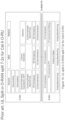
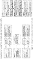
- Figure 1A illustrates the conventional UL functional split in O-RAN split 7-2x for Cat A O-RU.
- Figure 1B illustrates the processing blocks of UL processing in a conventional ORAN split 7-2x for Cat A O-RU. As illustrated in Figure 1B , the operations in O-RAN split 7-2x for UL processing for Cat A 0-RU are as follows:
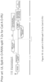
- FIG. 2A illustrates the conventional UL functional split in O-RAN split 7-2x for Cat B O-RU
- Figure 2B illustrates the conventional processing blocks of UL processing in ORAN split 7-2x for Cat B O-RU.
- the operations in O-RAN split 7-2x for UL processing for Cat B 0-RU are as follows:
- One drawback of O-RAN operation with Cat B O-RU is that the combining/digital beamforming matrix elements are calculated using SRS channel estimates (at O-DU) at a slot n-M which is earlier than the current slot n. Since the channel may change during the M slots between slot n-M and slot n, the combining/digital beamforming matrix may not properly match the UL channel of slot n. This can result in some performance degradation, particularly for UEs with higher mobility. Also, since O-DU operates on a combined version of the signal received from O-RU in slot n (not the full-dimension signal), the interference rejection performance in O-DU may be degraded.
- the present invention relates to Open Radio Access Network (O-RAN) system and to a method of operating the same, as defined in the annexed claims.
- OF-RAN Open Radio Access Network
- Implementations as described herein provide methods to enable an efficient mMIMO system for O-RAN based RANs.
- Implementations as described herein address the aforementioned issues of performance degradation of the 0-RAN 7-2x based UL MIMO. Aspects of the implementation include the following:
- Asymmetrical functional split (using different functional splits in DL and UL):
- the functional split point in the UL is changed so that further signal processing can be done at O-RU.
- O-RU performs a first level of DM-RS channel estimation on PUSCH/PUCCH and uses the result of this channel estimation to calculate the combining/digital beamforming matrix, and after performing combining/digital beamforming on the received signal, transfers the resulting signal to O-DU for the rest of processing.
- O-RU performs both DM-RS channel estimation and equalization on PUSCH/PUCCH and transfers the equalized signal to 0-DU for the rest of the processing.
- 0-RU performs DM-RS channel estimation, equalization, and demodulation on PUSCH/PUCCH and transfers the resulting demodulated signal to 0-DU for the rest of the processing. Described are multiple signaling (between O-DU and O-RU) and processing options for functional splits.
- the O-RU reports, via the M-plane, to the O-RU controller as part of its capability the supported split points and supported techniques (e.g., channel estimation techniques, MIMO detection techniques, etc.).
- the O-RU controller statically configures, via the M-plane, the O-RU with the static parameters and static configurations based on the reported capabilities to operate using specific methods.
- new sections and section extensions to the C-plane messages are proposed to carry, in real-time, the parameters and configurations at the 0-RU to enable operation in an innovative split architecture.
- Implementations as described herein provide methods to enable an efficient mMIMO system for O-RAN based RANs.
- FIGS 3A , 3B , and 3C illustrate innovative embodiments of UL functional splits O-RU categories.
- Three different O-RU categories, namely, O-RU Cat C1, C2, and C3, are as follows:
- Cat A Cat C3 O-RU performs "DM-RS based Channel Estimation”, “Equalization”, and “Demodulation” in the UL.
- Cat B Cat C1 O-RU performs "DM-RS based Channel Estimation” in the UL.
- Cat B Cat C2 O-RU performs "DM-RS based Channel Estimation” and “Equalization” in the UL.
- Cat B Cat C3 O-RU performs "DM-RS based Channel Estimation”, “Equalization”, and “Demodulation” in the UL.
- Embodiment 1 describes the processing steps for UL functional split with O-RU Cat C1, in which O-RU performs a "DM-RS based Channel Estimation" in the UL.
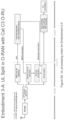
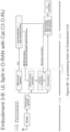
- Figures 4A , 4B , 4C , and 4D are flowcharts of UL Split in O-RAN with Cat C1 O-RU.
- O-RU performs the following steps to process the received signal: As shown in Figure 4A , at 1-1), prior to slot n, O-DU transfers "DM-RS information" to O-RU so that O-RU can obtain the DM-RS signal and perform channel estimation.
- DM-RS information Some options for the "DM-RS information" are as follows:
- O-DU transfers the "DM-RS channel estimation method information" to 0-RU to indicate the "channel estimation method” and possibly “details of the indicated channel estimation method".
- Exemplary channel estimation methods are listed below:
- Embodiment 7 Channel Estimation.
- the “details of the indicated channel estimation method” depends on the indicated channel estimation method and may include any of the following:
- Indication of the "channel estimation method” and/or “details of the indicated channel estimation method” can be done based on one of the following options:
- O-DU transfers "combining/digital beamforming matrix enhancement information" to O-RU prior to slot n. This information improves the quality of the combining/digital beamforming matrix when it is calculated by the O-RU.
- O-RU estimates the UL channels of the UE(s) and/or layer(s) transmitted at the current slot n using the "DM-RS information" obtained in Step 1-1.
- Step 1-2 one of the following options are taken by O-RU regarding the channel estimation method and its details:
- O-DU indicates "combining/digital beamforming matrix calculation method" to O-RU.
- Some examples for the combining/digital beamforming matrix calculation method are as follows:
- O-RU calculates the "combining/digital beamforming matrix" either based on the calculation method provided by O-DU in Step 1-5 (if Step 1-5 is executed) or based on a pre-configured method (if Step 1-5 is not executed).
- Step 1-5 the calculation method provided by O-DU in Step 1-5
- Step 1-5 the calculation method provided by O-DU in Step 1-5
- Step 1-5 the calculation method provided by O-DU in Step 1-5
- Step 1-5 is executed
- a pre-configured method if Step 1-5 is not executed.
- Step 1-3 one of the following options are taken by O-RU:
- O-RU applies the calculated "combining/digital beamforming matrix" to the received signal in slot n and transfers the resulting signal to O-DU through the fronthaul link.
- O-DU performs DM-RS channel estimation on the signal of slot n transferred from O-RU and subsequently performs UL MIMO processing by equalizing the channel using the estimated channel (with optional inter-cell interference rejection). Afterward, O-DU performs the rest of L1/L2 processing on the resulting signal.
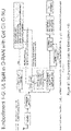
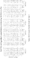
- Figures 5A , 5B , 5C , 5D , 5E , 5F , 5G , and 5H illustrate different variations of Embodiment 1 to enable 0-RU Cat C1 through different signaling mechanisms.
- Embodiment 2 describes the processing steps for UL functional split with O-RU Cat C2, in which O-RU performs the "DM-RS based Channel Estimation" and "Equalization” in the UL.
- Figures 6A , 6B , and 6C present a flowchart of UL Split in O-RAN with Cat C2 O-RU.
- O-RU performs the following steps to process the received signal:
- O-DU transfers "DM-RS information" to O-RU so that O-RU can obtain the DM-RS signal and perform channel estimation.
- O-DU transfers the "DM-RS channel estimation method information" to O-RU to indicate the "channel estimation method” and possibly “details of the indicated channel estimation method".
- Exemplary channel estimation methods are listed below:
- Embodiment 7 Channel Estimation below.
- the "details of the indicated channel estimation method” depends on the indicated channel estimation method and may include any of the following:
- Indication of the "channel estimation method” and/or “details of the indicated channel estimation method” can be done based on one of the following options:
- O-RU estimates the UL channels of the UE(s) and/or layer(s) transmitted at the current slot n using the "DM-RS information" obtained in Step 2-1.
- Step 2-2 one of the following options are taken by O-RU regarding the channel estimation method and its details:
- O-DU transfers the "channel equalization information" to O-RU to indicate the "channel equalization method” and possibly further details of the channel equalization procedure through the "additional channel equalization information".
- exemplary channel equalization methods are listed below:
- Embodiment 8 Channel Equalization below.
- the “additional channel equalization information" of the demodulation procedure during the log-likelihood ratio (LLR) calculation can be provided in several ways. Based on the indicated “additional channel equalization information", which may be a part of the “channel equalization information”, the supplementary demodulation information is calculated. Exemplary “additional channel equalization information” options are listed below:
- O-RU equalizes the UL channels of the UE(s) and/or layer(s) transmitted at the current slot n.
- Step 2-4-A one of the following options are taken by O-RU regarding the "channel equalization method information":
- O-RU calculates the "supplementary demodulation information" and transfers it along with the equalized signal stream(s) to O-DU through the fronthaul link.
- O-RU calculates the "supplementary demodulation information" and transfers it along with the equalized signal stream(s) to O-DU through the fronthaul link.
- the optional 2-4-B is executed, one of the following options are taken by O-RU regarding the "additional channel equalization information":
- O-DU performs demodulation on the signal of slot n transferred from O-RU and subsequently performs the rest of L1/L2 processing on the resulting signal.
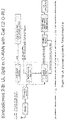
- Figures 7A , 7B , and 7C illustrate different variations of Embodiment 2 to enable O-RU Cat C2 through different signaling mechanisms, as summarized Table 2.
- Table 3 Summary of selected embodiments from embodiment 2 Embodiment # Executed steps from Embodiment 2 Block diagram 2-A (2-1), (2-3), (2-5), (2-6), (2-7) Figure 7A 2-B (2-1), (2-2), (2-3), (2-5), (2-6), (2-7) Figure 7B 2-C (2-1), (2-2), (2-3), (2-4), (2-5), (2-6), (2-7) Figure 7C
- Embodiment 3 describes the processing steps for UL functional split with O-RU Cat C3, in which O-RU performs the "DM-RS based Channel Estimation", “Equalization”, and “Demodulation” in the UL.
- Figures 8A , 8B , and 8C are a flowchart of UL Split in O-RAN with Cat C3 O-RU.
- O-RU performs the following steps to process the received signal: As shown in Figure 8A , at 3-1, prior to slot n, O-DU transfers "DM-RS information" to O-RU so that O-RU can obtain the DM-RS signal and perform channel estimation.
- DM-RS information Some options for the "DM-RS information" are as follows:
- O-DU transfers the "DM-RS channel estimation method information" to O-RU to indicate the "channel estimation method” and possibly “details of the indicated channel estimation method".
- Exemplary channel estimation methods are listed below:
- Embodiment 7 Channel Estimation.
- the "details of the indicated channel estimation method” depends on the indicated channel estimation method and may include any of the following:
- O-RU estimates the UL channels of the UE(s) and/or layer(s) transmitted at the current slot n using the "DM-RS information" obtained in Step 3-1.
- Step 3-2 one of the following options are taken by O-RU regarding the channel estimation method and its details:
- O-DU transfers the "channel equalization method information" to O-RU to indicate the type and, possibly, further details of the channel equalization method to be adopted by O-RU.
- channel equalization method may refer to any of the following example channel equalization techniques:
- O-RU equalizes the UL channels of the UE(s) and/or layer(s) transmitted at the current slot n.
- Step 3-4 one of the following options are taken by O-RU regarding the "channel equalization method information":
- O-DU transfers "modulation information" to O-RU.
- O-RU performs demodulation on the equalized signal in Step 3-5 during slot n and transfers the resulting signal to O-DU through the fronthaul link.
- O-DU performs descrambling on the signal of slot n transferred from O-RU and subsequently performs the rest of L1/L2 processing on the resulting signal.
- Figures 9A , 9B , and 9C illustrate different variations of Embodiment 3 to enable O-RU Cat C3 through different signaling mechanisms, as shown in Table 4.
- Table 4 Summary of selected embodiments from embodiment 3 Embodiment # Executed steps from Embodiment 2 Block diagram 3-A (3-1), (3-3), (3-5), (3-6), (3-7) Figure 9A 3-B (3-1), (3-2), (3-3), (3-5), (3-6), (3-7) Figure 9B 3-C (3-1), (3-2), (3-3), (3-4), (3-5), (3-6), (3-7) Figure 9C
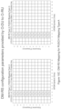
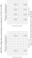
- Figures 10A , 10B , 10C , 10D , and 10E clarify the 5G NR DM-RS structures with examples for a better understanding.
- Example Tables 5-20 show exemplary parameters for the signaling mechanisms that enables asymmetrical functional splits as shown in Figures 10A , 10B , 10C , 10D , and 10E .
- Table 4 DM-RS configuration parameters Purpose Parameter Brief Description Value Range Waveform Selection TransformPrecoding Enable/disable transform precoding ⁇ 0,1 ⁇ DMRS Sequence Generation N ID n SCID DMRS Scrambling Identity (for CP-OFDM) ⁇ 0,1, ..., 65535 ⁇ n SCID DMRS Scrambling Initialization ⁇ 0,1 ⁇ N symb slot Number of OFDM Symbols in a Slot ⁇ 12,14 ⁇ n s , f ⁇ Slot Number in a Radio Frame ⁇ 0, ..., 159 ⁇ l Symbol Number within a Slot ⁇ 0,1, ...,13 ⁇ n ID RS DM-RS Scrambling Identity (for DFT-s-OFDM) ⁇ 0,1, ..., 65535 ⁇ dmrsGH Group Hopping ⁇ 0,1 ⁇ dmrsSH Sequence Hopping ⁇ 0,1 ⁇ DMRS Configuration dmrs-Type DMRS Configuration Type ⁇ 1,
- Bitfield Window type 00 Type 1 01 Type 2 10 Type 3 11 Type 4 Table 9 An example look-up table for window size.
- Channel estimation method CE Granularity in the Frequency Domain ( Integer Values for #RBs ) SINR 0 (IQ Values) ⁇ RMS ( IQ Values) ⁇ max ( IQ Values) Window type (Indicator for a row in a table) Window size (Integer Values) LS ü - - - - MMSE ü ü ü ü - - DFT based ü - - ü ü DCT based ü - - ü ü Table 12: A summary of channel estimation methods and their corresponding details for option 1-2-C (Example-2).
- Channel estimation method CE Granularity in the Frequency Domain (Integer Values for #RBs) MMSE matrix (IQ Values) Window type (Indicator for a row in a table) Window size (Integer Values) LS ü - - - MMSE ü ü - - DFT based ü - ü ü DCT based ü - ü ü Table 16: An example look-up table for the combining / digital beamforming matrix calculation methods Bitfield Combining/digital beamforming matrix calculation method 000 Conjugate combining 001 Zero forcing 010 MMSE 011 MMSE- IRC 100 Null-space dimension increase based 101 DFT-compression Table 17: An example look-up table for the channel equalization methods Bitfield Channel equalization method 00 Zero forcing 01 MMSE 10 MMSE- IRC Table 18: An example look-up table for the additional channel equalization information Bitfield Supplementary Demodulation Information Calculation Method 000 Equalization Gain and Post-processed Noise plus Interference Power
- the O-RU exposes its ability to support category C1, category C2, or category C3 to the SMO or the O-RU controller in the O-RAN module-cap.yang.
- category C1, category C2, or category C3 to the SMO or the O-RU controller in the O-RAN module-cap.yang.
- One example of the RU-supported-category leaf under the RU-capabilities structure in the O-RAN-module-cap.yang can be shown as follows:
- the O-RU exposes its ability to support DM-RS-based channel estimation locally and the dependent features by supporting of the feature DMRS-BASED-CHANNEL-ESTIMATION-SUPPORTED in o-ran-module-cap.yang module.
- the O-DU appends the UL C-plane message sent in the DL to the O-RU with the following section extension and includes the DM-RS configuration parameters to enable the O-RU to locally generate the DM-RS signal.
- ExtType 21: Section description for DMRS sequence generatio
- Section Extension Type 21 ef extType 0x15 1 Octet N extLen 1 N+1 TP scramblinglnit GH SH configType maxLen pos reserved 1 N+2 scramblingID[15:8] 1 N+3 scramblingID [7:0] 1 N+4 addPos[1:0] antPortInd[3:0] reserved 1 N+5 zero pad to 4-byte boundary 1 N+6 zero pad to 4-byte boundary 1 N+7
- M-plane Embodiment for static DMRS sequence generation If dmrs-local-generation and static-dmrs-based-channel-estimation-configuration-type features are supported by the O-RU and configured by the SMO/O-RU controller, the SMO/O-RU controller statically configures the DM-RS parameters to enable the O-RU to locally generate the DM-RS signal and execute DMRS-based channel estimation.
- the O-DU appends the UL C-plane message sent in the DL to the O-RU with the following section extension and includes the DM-RS sequence to enable the O-RU to do DMRS-based channel estimation.
- ExtType 22: Section description for DMRS sequence transmission
- This section extension applies to DMRS signal transmission. This enables the O-DU to provide the DMRS sequence needed at the O-RU to execute DMRS-based channel estimation. This section extension applies to section types 1 and 3.
- the O-DU configures the O-RU in real time with the channel estimation method and needed parameters to enable the O-RU to do channel estimation locally.
- Section Extension Type 23 ef extType 0x17 1 Octet N extLen 1 N+1 chEstMeth mmseMatrixId chEstGranularity 1 N+2 windowType windowSize reserved 1 N+3
- DM-RS is used for channel estimation as part of coherent demodulation of the physical channels (i.e., PUSCH/PDSCH). It is designed to support various use cases, channel conditions, and deployment scenarios.
- DM-RS configuration depends on other PHY layer parameters such as the resource allocation type and utilized waveform (i.e., CP-OFDM or DFT-s-OFDM), and these are detailed in the following parts.
- CP-OFDM or DFT-s-OFDM the resource allocation type and utilized waveform
- either DM-RS sequence or DM-RS configuration parameters which are required to generate DM-RS sequence at O-RU, need to be provided by O-DU to O-RU.
- Figures 11A , 11B , 11C , 11D , and 11E demonstrate the possible channel estimation techniques that can be applied at the O-RU.
- a length-31 Gold sequence is used as the DM-RS sequence for CP-OFDM (i.e., when transform precoding is disabled).
- c init 2 17 N symb slot n s , f ⁇ + l + 1 2 N ID n SCID + 1 + 2 N ID n SCID + n SCID mod 2 31
- l is the OFDM symbol number within the slot
- n s f ⁇ is the slot number within a frame.
- N ID n SCID denotes the DM-RS scrambling identity
- n SCID represents DM-RS scrambling initialization parameter.
- the Zadoff-Chu sequence is used as the DM-RS sequence for DFT-s-OFDM (i.e., when transform precoding is enabled).
- the base sequences, r u,v ( n ) are divided into groups, where u ⁇ ⁇ 0,1,2, ..., 29 ⁇ specifies the group number and v ⁇ ⁇ 0,1 ⁇ represents the base sequence number within the group.
- the base sequence definition depends on the sequence length as follows:
- the low-PAPR sequence parameters ⁇ is given as 1 and the cyclic shift, ⁇ , is set to 0 for a PUSCH transmission.
- the sequence group number, u equals to f gh + n ID RS mod 30 , where n ID RS denotes the DM-RS scrambling identity.
- the values of f gh and the base sequence number, v are given as follows:
- the orthogonality of the DM-RS sequences that are allocated to the different antenna ports is achieved by multiplexing in time, frequency, and code domains. To realize this, the DM-RS sequence is multiplied with the orthogonal cover codes in time and frequency domains (i.e., w t ( k ) and w f ( k ) respectively). Also, shifts in the frequency domain are included to support more antenna ports.
- w f ( k' ) , w t ( l' ) , and ⁇ are defined by Tables 6.4.1.1.3-1 and Tables 6.4.1.1.3-2 in TS 38.211.
- p ⁇ j represents the antenna port for transmission layer j.
- DFT-s-OFDM supports only single-layer transmission
- DM-RS configuration type determines the DM-RS density in the frequency domain, which also impacts the available number of orthogonal sequences.
- DM-RS configuration Type 1 has a higher density in the frequency domain and provides a more accurate channel estimation.
- DM-RS configuration Type 2 has a lower density in the frequency domain, and it allows supporting more antenna ports. Type 1 can support up to 8 antenna ports, whereas Type 2 can support up to 12 antenna ports.
- the reference point for k depends on the waveform type. For CP-OFDM (i.e., when transform precoding is disabled), k is subcarrier 0 in the common resource block. On the other hand, for DFT-s-OFDM (i.e., when transform precoding is enabled), k is subcarrier 0 of the lowest-numbered RB of the scheduled PUSCH allocation.
- the reference point of l and the position of the first DM-RS symbol ( l 0 ) depends on the PUSCH mapping type and activation of the frequency hopping scheme.
- l is defined relative to the start of the slot if frequency hopping is disabled, and it is defined relative to the start of each hop if frequency hopping is enabled.
- l 0 is indicated by dmrs - TypeA - Position parameter, and it refers to either the third or fourth OFDM symbol in a slot.
- PUSCH Mapping Type B l is defined relative to the start of the scheduled PUSCH resources if frequency hopping is disabled, and it is defined relative to the start of each hop if frequency hopping is enabled.
- l 0 equals to 0; in other words, it refers to the first symbol in the scheduled data symbol duration.
- Exemplary DM-RS mappings are illustrated in Figures 10C and 10D for PUSCH Mapping Type A and PUSCH Mapping Type B accordingly.
- the position(s) of the DM-RS symbols is provided by l parameter and it depends on the PUSCH mapping type, activation of the frequency hopping scheme, and the number of additional DM-RS symbols. Up to 4 DM-RS symbols (i.e., up to 3 additional positions) in a slot are possible for high mobility scenarios. Exemplary DM-RS allocations with additional positions are presented in Figure 10E .
- the position(s) of the DM-RS symbols ( l ), the time-domain index ( l '), and the supported antenna ports p ⁇ j are provided by Tables 6.4.1.1.3-3 through 6.4.1.1.3-6 in TS 38.211
- the required ⁇ DMRS value is signaled with the number of DM-RS CDM groups without data parameter. Also, W is given by Table 6.3.1.5-1 to Table 6.3.1.5.-7 in TS 38.211.
- the required precoding matrix is signaled through the TPMI index parameter.
- the DM-RS sequence can either be sent from O-DU to O-RU or the DM-RS configuration parameters, which are required to re-generate the DM-RS sequence in the O-RU, can be transmitted from O-DU to O-RU.
- Y received signal vector
- X is a diagonal matrix where each diagonal element represents a reference signal (such as DM-RS) in subcarrier k
- H is the channel vector
- Z is the noise vector.
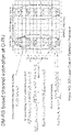
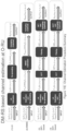
- FIG. 11 E is flow chart showing 4 exemplary implementations for DM-RS channel estimation techniques, described in more detail with respect to FIGS. 11A-11D .
- Examples of DM-RS channel estimation techniques that O-RU can use include the following:
- Figure 11A illustrates an LS channel estimation.
- Figure 11B illustrates an MMSE channel estimation.
- the MMSE finds a better linear estimate (i.e., W ⁇ ) that minimizes the minimum square error (MSE), which is calculated as E ⁇ H - ⁇ ⁇ 2 ⁇ .
- MSE minimum square error
- n RB represents the RB index
- n s shows the slot index
- I and J represents the total number of subcarriers and symbols that are used in this averaging operation.
- the channel estimates belong to multiple RBs can be averaged as well.
- a DFT-based channel estimation is illustrated in Figure 11C .
- the performance of channel estimation (LS or MMSE) can be improved with a DFT-based channel estimation technique by filtering the noise outside the maximum delay of the channel.
- the channel taps that are below a certain threshold value are set to 0. This threshold value can be calculated by the average energy of the channel taps outside the window.
- the channel estimates belong to multiple RBs can be averaged as well.
- a DCT based channel estimation is illustrated in Figure 11D.
- the performance of channel estimation can be improved with a DCT-based channel estimation technique by filtering the noise outside the maximum delay of the channel, similar to the DFT-based estimation.
- the DCT-based estimation provides better power concentration and lower aliasing error than the DFT-based interpolation.
- the channel taps that are below a certain threshold value are set to 0. This threshold value can be calculated by the average energy of the channel taps outside the window.
- H ⁇ DCT ′ k i l j r m t n IDCT h ⁇ thresholded DCT n i l j r m t n
- H ⁇ DCT n RB n s r m t n ⁇ i , j I , J H ⁇ DCT ′ k i l j r m t n I ⁇ J
- the channel estimates belong to multiple RBs can be averaged as well, similar to the other channel estimation techniques that are described previously.
- Examples of channel equalization techniques that O-RU can use include the following:
- Y DS represents the frequency domain data symbols
- X shows the transmitted signal
- H is the estimated channel response
- Z is the noise
- k denotes the subcarrier index
- r shows the receiver antenna index
- t represents the DM-RS transmission port index
- N t
- An interpolation operation in the time/frequency domains is required to calculate the covariance matrix in the scheduled subcarriers.
- the demodulation procedure requires "additional channel equalization information" during the log-likelihood ratio (LLR) calculation, and it can be provided in several ways.
- a universal solution which is independent of the equalization method, can be providing one of the following options:
- the post-processed noise plus interference power refers to the noise plus interference power that is obtained after the equalization procedure. Also, it should be noted that in the case of options (b) and (c), the equalized signal should be normalized by either equalization gain or post-processed noise plus interference power, respectively.
- H is a matrix of size N RX ⁇ N UE where N RX is the number of RX antennas at BS and N UE is the number of UEs or layers being simultaneously transmitted over the same resources on the PUSCH slot.
- N RX is the number of RX antennas at BS
- N UE is the number of UEs or layers being simultaneously transmitted over the same resources on the PUSCH slot.
- H is an estimation of the UL channel, for example, based on SRS or DM-RS or a combination thereof or a linearly predicted UL channel based on SRS channel estimation.
- Channel the contiguous frequency range between lower and upper frequency limits.
- Control Plane refers specifically to real-time control between O-DU and O-RU, and should not be confused with the UE's control plane
- LLS Lower Layer Split: logical interface between O-DU and O-RU when using a lower layer (intra-PHY based) functional split.
- M-Plane Management Plane: refers to non-real-time management operations between the O-DU and the O-RU
- O-CU O-RAN Control Unit - a logical node hosting PDCP, RRC, SDAP and other control functions
- O-DU O-RAN Distributed Unit: a logical node hosting RLC/MAC/High-PHY layers based on a lower layer functional split.
- O-RU O-RAN Radio Unit: a logical node hosting Low-PHY layer and RF processing based on a lower layer functional split. This is similar to 3GPP's "TRP" or "RRH” but more specific in including the Low-PHY layer (FFT/iFFT, PRACH extraction).
- Synchronization Plane refers to traffic between the O-RU or O-DU to a synchronization controller which is generally an IEEE 1588 Grand Master (however, Grand Master functionality may be embedded in the O-DU).
- U-Plane refers to IQ sample data transferred between O-DU and O-RU
Landscapes
- Engineering & Computer Science (AREA)
- Signal Processing (AREA)
- Computer Networks & Wireless Communication (AREA)
- Power Engineering (AREA)
- Physics & Mathematics (AREA)
- Mathematical Physics (AREA)
- Theoretical Computer Science (AREA)
- Mobile Radio Communication Systems (AREA)
Abstract
Description
- The present application claims priority to
U.S. Provisional Patent Application No. 63/244,774, filed on September 16, 2021 U.S. Provisional Patent Application No. 63/257,811, filed on October 20, 2021 U.S. Provisional Patent Application No. 63/300,108, filed on January 17, 2022 - The present disclosure relates to systems and methods for operating the Radio Access Network (RAN) design for 4G- and 5G-based mobile networks, and relates more particularly to systems and methods to enable efficient uplink mMIMO performance for Open-RAN (O-RAN).
- Traditionally, the radio access networks were built as an integrated unit where the entire RAN was processed. The RAN network traditionally uses application-specific hardware for processing, making them difficult to upgrade and evolve. As future networks evolve to have massive densification of networks to support increased capacity requirements, there is a growing need to reduce the CAPEX/OPEX costs of RAN deployment and make the solution scalable and easy to upgrade.
- In the field of cloud-based Radio Access Networks (RAN), a significant portion of the RAN layer processing is performed at a central unit (CU) and a distributed unit (DU). Both CUs and DUs are also known as the baseband units (BBUs). CUs are usually located in the cloud on commercial off-the-shelf servers, while DUs can be distributed. Also, the RF and real-time functions can be processed in the remote radio unit (RU).
- The context of the present disclosure is related to systems and methods to enable efficient uplink mMIMO performance for O-RAN-based RANs.
- 3GPP has defined multiple split options across the entire radio access network (RAN). There are various factors affecting the selection of the fronthaul split option, such as bandwidth, latency, implementation cost, virtualization benefits, complexity of the fronthaul interface, expansion flexibility, computing power, and memory requirement
- One of the most common splits that are standardized recently by the O-RAN alliance is split option 7-2x (Intra-PHY split). This split has multiple advantages such as simplicity, transport bandwidth scalability, beamforming support, interoperability, support for advanced receivers and inter-cell coordination, lower O-RU complexity, future proof-ness, and interface and functions symmetry.
- One of the technologies that use the O-RAN 7-2x specifications is 4G/5G massive MIMO (mMIMO). In SU-MIMO, the gNB serves a single user on a set of time-frequency resources, whereas in MU-MIMO setup, the gNB serves multiple users on the same time-frequency resources. In UL, UEs send SRS signals over a relatively long period of time, which are sent to the O-DU from the O-RU via the fronthaul interface. Using the SRS signal, the O-DU then obtains the UL channel estimates of the UEs, using which gNB performs user pairing (in the case of MU-MIMO) and calculates UL combining/digital beamforming matrix for the scheduled user(s). The O-DU sends the combining/digital beamforming matrix elements or weights to the 0-RU, which in return applies these elements to the frequency-domain PUSCH IQ samples received at a later time and sends the resulting IQ samples to the O-DU for the rest of PHY processing. One aspect of the combining operation (using the combining/digital beamforming matrix) at O-RU is that it enables the O-RU to reduce the number of streams transferred from O-RU to O-DU to a value smaller than the number of RX antennas. In mMIMO systems, the number of RX antennas is large, and transferring all received streams for PUSCH to 0-DU incurs significant and prohibitive front-haul bandwidth consumption.
- Although split option 7-2x enables multiple advanced features, such as beamforming and UL CoMP, the system performance may degrade in certain scenarios, such as UL mMIMO for high-speed UEs and/or interference-limited scenarios, where there is significant inter-cell interference (ICI) from neighboring cells contaminating the UL signal from the desired UEs.
- Performance degradation in high mobility scenarios: The reason for such degradation in high-speed UEs scenarios is channel aging. Specifically, the SRS signals are sent over a relatively long period of time (e.g., 10s of milliseconds). By the time the O-RU applies the combining/digital beamforming matrix elements to the PUSCH symbols, these matrix elements become inaccurate since the SRS signals are outdated (i.e., SRS to UL-data TTI delay is long). In other words, the channel gains between the UEs and the gNB at the time PUSCH is received are no longer reflected accurately by the SRS signals (since UEs are moving fast in such a scenario), which cause interference and hence throughput degradation during the combining process (using the combining/digital beamforming matrix) in the UL chain.
- Performance degradation in the presence of inter-cell interference (ICI) : The main reason for performance degradation in the presence of ICI is signal dimension reduction at O-RU. In particular, squeezing desired signal and interference signal into a smaller number of dimensions causes performance degradation of the interference rejection at O-DU.
- One way to mitigate the performance degradation in high mobility scenarios is to configure SRS transmissions with shorter periodicities. However, shorter SRS periodicity may decrease the SRS capacity, i.e., the number of UEs that can be configured to transmit SRS, because more resources are occupied by each UE for SRS transmission. Also, in a time-division duplex (TDD) system, there are certain limitations on SRS periodicity due to the TDD frame structure adopted by the system.
- Another approach to mitigate the performance degradation in high mobility scenarios is to predict the UL channel of the PUSCH/PUCCH slot at DU based on UL channels of a number of previous SRS transmissions. In addition to the computation complexity of the underlying prediction algorithm, this approach has its own limitations on performance improvement depending on UE speeds.
- For scenarios with inter-cell interference, a typical O-DU processing uses a minimum mean-squared error receiver with interference rejection combining (MMSE-IRC) to mitigate the impact of the interference. However, since O-DU has access to the compressed PUSCH signal transferred from 0-RU, the performance of MMSE-IRC may be degraded compared to a typical 7-3 receiver wherein MMSE-IRC is computed based on and applied to the full-dimension signal.
- There are four planes specified in the O-RAN specs, namely user-plane (U-plane), control plane (C-plane), synchronization plane (S-plane), and management plane (M-plane). The existing 0-RAN spec explains the exact method of sending the C-plane messages in the downlink (DL) direction and sending/receiving the U-plane messages between the O-DU and the O-RU.
- The M-plane specifies the management plane protocols used over the fronthaul interface linking the O-RU (O-RAN Radio Unit) with other management plane entities, which can include the O-DU (O-RAN Distributed Unit), the O-RAN defined Service Management and Orchestration (SMO) functionality as well as other generic Network Management Systems (NMS).
- In contrast to C-plane (described in the next section), Management Plane refers to non-real-time management operations between the O-DU and the O-RU. Specifically, The Lower-Layer Split M-plane (LLS-M) facilitates the initialization, configuration, and management of the O-RU to support the stated functional split.
- A NETCONF/YANG-based M-Plane is used for supporting the management features, including "startup" installation, software management, configuration management, performance management, fault management, and file management towards the O-RU. The M-Plane supports two architectural models:
- 1. Hierarchical model: The O-RU is managed entirely by one or more O-DU(s) using a NETCONF based M-Plane interface. When the O-RU is managed by multiple 0-DUs, it is typically for enabling O-DU and/or transport connectivity redundancy capabilities.
- 2. Hybrid model: The hybrid architecture enables one or more direct logical interface(s) between management system(s) and O-RU in addition to a logical interface between O-DU and the O-RU. Based on the transport topology, various modes of network connectivity are possible between O-RU and O-DU and SMO. The basic requirement for M-Plane is to have end-to-end IP connectivity between the O-RU and the elements managing it (O-DU, SMO, or socalled "O-RU Controllers").
- The M-Plane provides the following major functionalities to the O-RU. These features are implemented using the NETCONF provided functions such as "Startup" installation, SW management, Configuration management, Performance management, Fault Management, and File Management The data models representing the M-Plane are organized as a set of reusable YANG modules.
- The purpose of the C-plane messages is to transmit data-associated control information required for the processing of user data (e.g., scheduling and beamforming commands). These messages are sent separately for DL-related commands and UL-related commands.
- A common frame format is used for C-Plane messages, having a transport layer and an application layer. The application layer is within the transport layer payload and consists of a common header for time reference, followed by information and parameters dependent and specific to the Section Type in use. Multiple sets of section data of the same Section Type value can be lined up one after another within the payload. To minimize packet rate over the interface, a transmitter should fill messages with as many subsequent sections (with or without sequential section IDs) as possible.
-
Section Type 1 is used for most Downlink and Uplink radio channels. In accord with O-RAN specifications, the fields ofSection type 1 can be explained as follows: - Transport Layer
- Application Layer
- o Common Header Fields
- ▪ dataDirection (data direction (gNB Tx/Rx)) field: 1 bit
- ▪ payloadVersion (payload version) field: 3 bits
- value = "1" shall be set (1st protocol version for payload and time reference format)
- ▪ filterIndex (filter index) field: 4 bits
- ▪ frameId (frame identifier) field: 8 bits
- ▪ subframeId (subframe identifier) field: 4 bits
- ▪ slotID (slot identifier) field: 6 bits
- ▪ startSymbolid (start symbol id) field: 6 bits
- ▪ numberOfsections (number of sections) field: 8 bits
- ▪ sectionType (section type) field: 8 bits
- value = "1" shall be set
- ▪ udCompHdr (user data compression header) field: 8
bits 11 - ▪ reserved (reserved for future use) field: 8 bits
- ∘ Section Fields
- ▪ sectionId (section identifier) field: 12 bits
- ▪ rb (resource block identifier) field: 1 bit
- ▪ symInc (symbol number increment command) field: 1 bit
- ▪ startPrbc (starting PRB of data section description) field: 10 bits
- ▪ numPrbc (number of contiguous PRBs per data section description) field: 8 bits
- ▪ reMask (resource element mask) field: 12 bits
- ▪ numSymbol (number of symbols) field: 4 bits
- ▪ ef (extension flag) field: 1 bit
- ▪ beamId (beam identifier) field: 15 bits
- o Common Header Fields
-
Figure 1A illustrates the conventional UL functional split in O-RAN split 7-2x for Cat A O-RU.Figure 1B illustrates the processing blocks of UL processing in a conventional ORAN split 7-2x for Cat A O-RU. As illustrated inFigure 1B , the operations in O-RAN split 7-2x for UL processing for Cat A 0-RU are as follows: - O-RU receives the sounding reference signal (SRS) signal(s) from the UE(s) at slot n-M, where M is a positive integer.
- O-RU applies ADC, CP removal, and FFT and transfers the frequency-domain (FD) IQ samples of the SRS over all the antennas to the O-DU using O-RAN U-plane message(s).
- O-DU performs channel estimation on the IQ samples of SRS received from O-RU. Also, using the estimated channels, it performs user scheduling (and user pairing in the case of MU-MIMO) to indicate which UEs are scheduled to transmit PUSCH over the same time-frequency resources at a later time.
- O-RU applies ADC, CP removal, and FFT and transfers the frequency-domain (FD) IQ samples of the received PUCCH/PUSCH over all the antennas to the O-DU using O-RAN U-plane message(s).
- 0-DU performs DM-RS channel estimation on the signal stream(s) of slot n received from 0-RU. Subsequently, O-DU performs UL MIMO processing by performing channel equalization using the estimated channel (with optional inter-cell interference rejection) and demodulation of the equalized signal stream(s) and performs the rest of L1/L2 processing on the resulting signal stream(s).
- One drawback of the O-RAN operation with Cat A O-RU is its large fronthaul throughput requirement, especially in massive MIMO scenarios.
-
Figure 2A illustrates the conventional UL functional split in O-RAN split 7-2x for Cat B O-RUFigure 2B illustrates the conventional processing blocks of UL processing in ORAN split 7-2x for Cat B O-RU. As illustrated inFigure 2B , the operations in O-RAN split 7-2x for UL processing for Cat B 0-RU are as follows: - 1) O-RU receives the sounding reference signal (SRS) signal(s) from the UE(s) at slot n-M, where M is a positive integer.
- O-RU applies ADC, CP removal, and FFT and transfers the frequency-domain (FD) IQ samples of the SRS over all the antennas to the O-DU using O-RAN U-plane message(s).
- O-DU performs channel estimation on the IQ samples of SRS received from O-RU. Also, using the estimated channels, it performs the following:
- O-DU performs user scheduling (and user pairing in the case of MU-MIMO) to indicate which UEs are scheduled to transmit PUSCH over the same time-frequency resources at a later time.
- O-DU calculates combining/digital beamforming matrix elements to be applied on the PUSCH received from UE(s) scheduled at a later time, i.e., at slot n.
- O-DU transfers the combining/digital beamforming matrix elements calculated at Step 3b to O-RU sometime earlier than slot n.
- O-RU applies ADC, CP removal, and FFT and then applies the combining/digital beamforming matrix elements on the received PUCCH/PUSCH signal of slot n and transfers the resulting layers to the O-DU.
- O-DU performs DM-RS channel estimation on the signal stream(s) of slot n received from 0-RU. Subsequently, O-DU performs UL MIMO processing by performing channel equalization using the estimated channel (with optional inter-cell interference rejection) and demodulation of the equalized signal stream(s) and performs the rest of L1/L2 processing on the resulting signal stream(s).
- One drawback of O-RAN operation with Cat B O-RU is that the combining/digital beamforming matrix elements are calculated using SRS channel estimates (at O-DU) at a slot n-M which is earlier than the current slot n. Since the channel may change during the M slots between slot n-M and slot n, the combining/digital beamforming matrix may not properly match the UL channel of slot n. This can result in some performance degradation, particularly for UEs with higher mobility. Also, since O-DU operates on a combined version of the signal received from O-RU in slot n (not the full-dimension signal), the interference rejection performance in O-DU may be degraded.
- The present invention relates to Open Radio Access Network (O-RAN) system and to a method of operating the same, as defined in the annexed claims.
- Implementations as described herein provide methods to enable an efficient mMIMO system for O-RAN based RANs.
- Implementations as described herein address the aforementioned issues of performance degradation of the 0-RAN 7-2x based UL MIMO. Aspects of the implementation include the following:
- Asymmetrical functional split (using different functional splits in DL and UL): In implementations, the functional split point in the UL is changed so that further signal processing can be done at O-RU. In one embodiment, O-RU performs a first level of DM-RS channel estimation on PUSCH/PUCCH and uses the result of this channel estimation to calculate the combining/digital beamforming matrix, and after performing combining/digital beamforming on the received signal, transfers the resulting signal to O-DU for the rest of processing. In another embodiment, O-RU performs both DM-RS channel estimation and equalization on PUSCH/PUCCH and transfers the equalized signal to 0-DU for the rest of the processing. In yet another embodiment, 0-RU performs DM-RS channel estimation, equalization, and demodulation on PUSCH/PUCCH and transfers the resulting demodulated signal to 0-DU for the rest of the processing. Described are multiple signaling (between O-DU and O-RU) and processing options for functional splits.
- Signaling mechanisms to enable asymmetrical functional splits: Described are C-plane message modifications and M-plane enhancements to enable different split architectures. To enable different asymmetrical functional splits mentioned above and allow interoperability across different O-RU and O-DU vendors, several M-plane and C/U-plane enhancements are described. In one embodiment, the O-RU reports, via the M-plane, to the O-RU controller as part of its capability the supported split points and supported techniques (e.g., channel estimation techniques, MIMO detection techniques, etc.). In another embodiment, the O-RU controller statically configures, via the M-plane, the O-RU with the static parameters and static configurations based on the reported capabilities to operate using specific methods. In another embodiment, new sections and section extensions to the C-plane messages are proposed to carry, in real-time, the parameters and configurations at the 0-RU to enable operation in an innovative split architecture.
-
-
Figure 1A illustrates the UL functional split in O-RAN split 7-2x for Cat A O-RU. -
Figure 1B illustrates the processing blocks of UL processing in ORAN split 7-2x for Cat A 0-RU. -
Figure 2A illustrates the UL functional split in 0-RAN split 7-2x for Cat B O-RU. -
Figure 2B illustrates the processing blocks of UL processing in ORAN split 7-2x for Cat B 0-RU. -
Figure 3A illustrates an embodiment of a UL functional split of an 0-RU Cat C1. -
Figure 3B illustrates an embodiment of a UL functional split of an O-RU Cat C2. -
Figure 3C illustrates an embodiment of a UL functional split of an O-RU Cat C3. -
Figure 4A is a flowchart of UL Split in O-RAN with Cat C1 O-RU. -
Figure 4B is a flowchart of UL Split in 0-RAN with Cat C1 O-RU. -
Figure 4C is a flowchart of UL Split in O-RAN with Cat C1 O-RU. -
Figure 5A illustrates an exemplary implementation of a signaling mechanism according toEmbodiment 1 to enable O-RU Cat C1 a signaling mechanism. -
Figure 5B illustrates an exemplary implementation of a signaling mechanism according toEmbodiment 1 to enable O-RU Cat C1 a signaling mechanism, -
Figure 5C illustrates an exemplary implementation of a signaling mechanism according toEmbodiment 1 to enable O-RU Cat C1 a signaling mechanism. -
Figure 5D illustrates an exemplary implementation of a signaling mechanism according toEmbodiment 1 to enable O-RU Cat C1 a signaling mechanism. -
Figure 5E illustrates an exemplary implementation of a signaling mechanism according toEmbodiment 1 to enable O-RU Cat C1 a signaling mechanism. -
Figure 5F illustrates an exemplary implementation of a signaling mechanism according toEmbodiment 1 to enable O-RU Cat C1 a signaling mechanism. -
Figure 5G illustrates an exemplary implementation of a signaling mechanism according toEmbodiment 1 to enable O-RU Cat C1 a signaling mechanism. -
Figure 5H illustrates an exemplary implementation of a signaling mechanism according toEmbodiment 1 to enable O-RU Cat C1 a signaling mechanism. -
Figure 6A is a flowchart of UL Split in O-RAN with Cat C2 O-RU. -
Figure 6B is a flowchart of UL Split in O-RAN with Cat C2 O-RU. -
Figure 6C is a flowchart of UL Split in O-RAN with Cat C2 O-RU. -
Figure 7A illustrates an exemplary implementation of a signaling mechanism according toEmbodiment 2 to enable O-RU Cat C2 a signaling mechanism. -
Figure 7B illustrates an exemplary implementation of a signaling mechanism according toEmbodiment 2 to enable O-RU Cat C2 a signaling mechanism. -
Figure 7C illustrates an exemplary implementation of a signaling mechanism according toEmbodiment 2 to enable O-RU Cat C2 a signaling mechanism. -
Figure 8A is a flowchart of UL Split in O-RAN with Cat C3 O-RU. -
Figure 8B is a flowchart of UL Split in O-RAN with Cat C3 O-RU. -
Figure 8C is a flowchart of UL Split in O-RAN with Cat C3 O-RU. -
Figure 9A illustrates an exemplary implementation of a signaling mechanism according toEmbodiment 3 to enable O-RU Cat C3 a signaling mechanism. -
Figure 9B illustrates an exemplary implementation of a signaling mechanism according toEmbodiment 3 to enable O-RU Cat C3 a signaling mechanism. -
Figure 9C illustrates an exemplary implementation of a signaling mechanism according toEmbodiment 3 to enable O-RU Cat C3 a signaling mechanism. -
Figure 10A shows an exemplary 5G NR DM-RS structure. -
Figure 10B shows an exemplary 5G NR DM-RS structure. -
Figure 10 shows an exemplary 5G NR DM-RS structure. -
Figure 10D shows an exemplary 5G NR DM-RS structure. -
Figure 10E shows an exemplary 5G NR DM-RS structure. -
Figure 11A shows a channel estimation technique that can be applied at the O-RU. -
Figure 11B shows a channel estimation technique that can be applied at the O-RU. -
Figure 11C shows a channel estimation technique that can be applied at the O-RU. -
Figure 11D shows a channel estimation technique that can be applied at the O-RU. -
Figure 11E is a flowchart showing channel estimation techniques that can be applied at the 0-RU described with respect otFigures 11A-11D . - Implementations as described herein provide methods to enable an efficient mMIMO system for O-RAN based RANs.
-
Figures 3A ,3B , and3C illustrate innovative embodiments of UL functional splits O-RU categories. Three different O-RU categories, namely, O-RU Cat C1, C2, and C3, are as follows: - O-RU Cat C1 (
Figure 3A ): O-RU performs a first level of DM-RS channel estimation on PUSCH/PUCCH and uses the result of this channel estimation to calculate the combining/digital beamforming matrix, and after performing precoding/digital beamforming on the received signal, transfers the resulting signal to O-DU for the rest of processing. - O-RU Cat C2 (
Figure 3B ): O-RU performs both DM-RS channel estimation and equalization on PUSCH/PUCCH and transfers the equalized signal stream(s) along with the supplementary demodulation information to 0-DU for the rest of the processing. - O-RU Cat C3 (
Figure 3C ): O-RU performs DM-RS channel estimation, equalization, and demodulation on PUSCH/PUCCH and transfers the resulting demodulated signal to O-DU for the rest of the processing. - In order to mitigate the issues of UL 7-2x, an asymmetrical functional split between DL and UL is proposed. The DL processing follows the 0-RAN split 7-2x (either Cat A or Cat B) to balance the tradeoff between O-RU complexity and fronthaul throughput, where the UL processing follows a new split architecture. Three different UL functional splits corresponding to three different innovative 0-RU categories are summarized in Table 1.
Table 1: A summary of possible options for DL and UL functional splits DL UL Brief Description Cat A Cat C1 O-RU performs "DM-RS based Channel Estimation" in the UL. Cat A Cat C2 O-RU performs "DM-RS based Channel Estimation" and "Equalization" in the UL. Cat A Cat C3 O-RU performs "DM-RS based Channel Estimation", "Equalization", and "Demodulation" in the UL. Cat B Cat C1 O-RU performs "DM-RS based Channel Estimation" in the UL. Cat B Cat C2 O-RU performs "DM-RS based Channel Estimation" and "Equalization" in the UL. Cat B Cat C3 O-RU performs "DM-RS based Channel Estimation", "Equalization", and "Demodulation" in the UL. - The following describes detailed processing steps for UL functional splits with O-RU Cat C1, O-RU Cat C2, O-RU Cat C3.
-
Embodiment 1 describes the processing steps for UL functional split with O-RU Cat C1, in which O-RU performs a "DM-RS based Channel Estimation" in the UL.Figures 4A ,4B ,4C , and4D are flowcharts of UL Split in O-RAN with Cat C1 O-RU. - As shown in
Figures 4A ,4B ,4C and4D , in this embodiment, O-RU performs the following steps to process the received signal:
As shown inFigure 4A , at 1-1), prior to slot n, O-DU transfers "DM-RS information" to O-RU so that O-RU can obtain the DM-RS signal and perform channel estimation. Some options for the "DM-RS information" are as follows: - Option 1-1-A: "DM-RS configuration parameters" of the scheduled or paired UEs/layers. O-RU generates the "DM-RS sequence" using the "DM-RS configuration parameters" received from O-DU. The "DM-RS configuration parameters" are summarized in Table 4. Also, the details of the "DM-RS sequence" generation and mapping using the "DM-RS configuration parameters" are provided below under section Embodiment 6: 5G NR DM-RS.
- Option 1-1-B: "DM-RS sequence" of the scheduled or paired UEs/layers.
- As shown in
Figure 4A , at 1-2 (Optional) Prior to slot n, O-DU transfers the "DM-RS channel estimation method information" to 0-RU to indicate the "channel estimation method" and possibly "details of the indicated channel estimation method". Exemplary channel estimation methods are listed below: - Least-squares (LS) channel estimation
- Minimum mean-squared error (MMSE) channel estimation
- Discrete Fourier transform (DFT) based channel estimation
- Discrete cosine transform (DCT) based channel estimation
- The above channel estimation methods are described in more detail in Embodiment 7: Channel Estimation. The "details of the indicated channel estimation method" depends on the indicated channel estimation method and may include any of the following:
- RMS delay spread of the channel (τ RMS )
- Maximum Doppler spread of the channel (Δƒmax )
- Initial SINR estimation (SINR 0)
- MMSE matrix elements
- Channel Estimation granularity in the frequency domain
- Window type
- Window size
- Indication of the "channel estimation method" and/or "details of the indicated channel estimation method" can be done based on one of the following options:
- Option 1-2-A: O-DU indicates the "channel estimation method" to the 0-RU using a particular bitfield in the signaling from O-DU to O-RU. O-RU determines the channel estimation details, including parameters and processing steps based on its own implementation. An example of a mapping between the bitfield content and corresponding channel estimation methods is provided in Table 5.
- Option 1-2-B: O-DU indicates "channel estimation method" and "details of the indicated channel estimation method" to the O-RU using particular bitfields in the signaling from O-DU to 0-RU. O-RU uses a table, such as Table 5, to find the channel estimation method and uses other look-up tables, such as Table 6 to Table 9, to obtain the channel estimation details using these indications from O-DU. A summary of channel estimation methods and their corresponding look-up table(s) is provided in Table 10.
- Option 1-2-C: O-DU provides "partial channel estimation details" to 0-RU, using which O-RU calculates full channel estimation details. In this option, the "DM-RS channel estimation method "information" includes the channel estimation method and its partial details as listed in
Tabel 11 to Table 14. O-RU calculates the channel estimation details, such as MMSE matrix, CE granularity in the frequency-domain, and window size, based on the channel estimation method and its received details from O-DU. The details of these channel estimation calculations can be found in Embodiment 7: Channel Estimation. - Option 1-2-D: O-DU provides "full channel estimation details" to O-RU. In this option, the "DM-RS channel estimation method information" includes the channel estimation method and its full details as listed in Table 15. O-DU transfers the channel estimation details by either indicating bits in a bitfield for a particular parameter or directly transferring IQ/integer values of relevant parameters to O-RU.
- As shown in
Figure 4B , at 1-3 (Optional) O-DU transfers "combining/digital beamforming matrix enhancement information" to O-RU prior to slot n. This information improves the quality of the combining/digital beamforming matrix when it is calculated by the O-RU. Some options for the "combining/digital beamforming matrix enhancement information" are as follows: - Option 1-3-A: "Combining/digital beamforming matrix enhancement information" includes SRS channel estimates of the scheduled or paired UEs/layers. Later in Step 1-6, O-RU combines SRS and DM-RS channel estimates using weighting coefficients. Options for the weighting coefficients of Option1-3-A:
- Option 1-3-A-1: O-RU either uses pre-configured weighting coefficients or determines the weighting coefficients based on other parameters.
- Option 1-3-A-2: O-DU provides the weighting coefficients to O-RU as part of "combining/digital beamforming matrix enhancement information".
- Option 1-3-B: "Combining/digital beamforming matrix enhancement information" includes preliminary combining/digital beamforming matrix elements corresponding to the scheduled or paired UEs/layers. This preliminary combining/digital beamforming matrix is calculated at O-DU prior to slot n using SRS channel estimates. Later in Step 1-6, O-RU combines its own calculated combining/digital beamforming matrix elements with the preliminary combining/digital beamforming matrix using weighting coefficients. Options for the weighting coefficients of Option1-3-B:
- Option 1-3-B-1: O-RU either uses pre-configured weighting coefficients or determines the weighting coefficients based on other parameters.
- Option 1-3-B-2: O-DU provides the weighting coefficients to O-RU as part of "combining/digital beamforming matrix enhancement information".
- As shown in
Figure 4B , at 1-4 O-RU estimates the UL channels of the UE(s) and/or layer(s) transmitted at the current slot n using the "DM-RS information" obtained in Step 1-1. Depending on whether the optional Step 1-2 is executed, one of the following options are taken by O-RU regarding the channel estimation method and its details: - Option 1-4-A: (Step 1-2 is not executed): O-RU uses a pre-configured channel estimation method and its details.
- Option 1-4-B: (Step 1-2 is executed): O-RU uses "DM-RS channel estimation method information" provided by O-DU to obtain the channel estimation method and its details.
- As shown in
Figure 4C , at 1-5 (Optional) O-DU indicates "combining/digital beamforming matrix calculation method" to O-RU. Some examples for the combining/digital beamforming matrix calculation method are as follows: - Conjugate combining
- Zero forcing
- MMSE
- MMSE-IRC
- Null-space dimension increase based
- DFT-compression
- An example of a mapping between the bitfield contents and corresponding combining/digital beamforming matrix calculation methods is provided in Table 16.
- As shown in
Figure 4C , at 1-6 O-RU calculates the "combining/digital beamforming matrix" either based on the calculation method provided by O-DU in Step 1-5 (if Step 1-5 is executed) or based on a pre-configured method (if Step 1-5 is not executed). Depending on whether the optional Step 1-3 is executed, one of the following options are taken by O-RU: - Option 1-6-A (Step 1-3 is not executed): O-RU calculates the "combining/digital beamforming matrix" based on the estimated DM-RS channel(s).
- Option 1-6-B (Step 1-3 with Option 1-3-A is executed): O-RU combines SRS channel estimates provided by O-DU with its own estimated DM-RS channel estimates using weighting coefficients. 0-RU calculates the "combining/digital beamforming matrix" based on the combined DM-RS and SRS channel estimates.
- Option 1-6-C (Step 1-3 with Option 1-3-B is executed): O-RU calculates the "combining/digital beamforming matrix" based on the estimated DM-RS channel(s), and using weighting coefficients, combines it with the SRS-based preliminary combining/digital beamforming matrix received from O-DU.
- As shown in
Figure 4D , at 1-7, O-RU applies the calculated "combining/digital beamforming matrix" to the received signal in slot n and transfers the resulting signal to O-DU through the fronthaul link. - As shown in
Figure 4D , at 1-8, O-DU performs DM-RS channel estimation on the signal of slot n transferred from O-RU and subsequently performs UL MIMO processing by equalizing the channel using the estimated channel (with optional inter-cell interference rejection). Afterward, O-DU performs the rest of L1/L2 processing on the resulting signal. -
Figures 5A ,5B ,5C ,5D ,5E ,5F ,5G , and5H illustrate different variations ofEmbodiment 1 to enable 0-RU Cat C1 through different signaling mechanisms. - Depending on the type of information provided by O-DU to 0-RU, different implementations are described, as illustrated in
Figures 5A to 5H and summarized in table 2Table 2: Implementations from embodiment 1 Embodiment # Executed steps from Embodiment 1 Block diagram 1-A (1-1), (1-4), (1-6), (1-7), (1-8) Figure 5A 1-B (1-1), (1-4), (1-5), (1-6), (1-7), (1-8) Figure 5B 1-C (1-1), (1-2), (1-4), (1-6), (1-7), (1-8) Figure 5C 1-D (1-1), (1-2), (1-4), (1-5), (1-6), (1-7), (1-8) Figure 5D 1-E (1-1), (1-3), (1-4), (1-6), (1-7), (1-8) Figure 5E 1-F (1-1), (1-3), (1-4), (1-5), (1-6), (1-7), (1-8) Figure 5F 1-G (1-1), (1-2), (1-3), (1-4), (1-6), (1-7), (1-8) Figure 5G 1-H (1-1), (1-2), (1-3), (1-4), (1-5), (1-6), (1-7), (1-8) Figure 5H -
Embodiment 2 describes the processing steps for UL functional split with O-RU Cat C2, in which O-RU performs the "DM-RS based Channel Estimation" and "Equalization" in the UL.Figures 6A ,6B , and6C present a flowchart of UL Split in O-RAN with Cat C2 O-RU. - As shown in
Figures 6A ,6B , and6C , in this embodiment, O-RU performs the following steps to process the received signal: - As shown in
Figure 6A , at 2-1 (Mandatory) Prior to slot n, O-DU transfers "DM-RS information" to O-RU so that O-RU can obtain the DM-RS signal and perform channel estimation. Some options for the "DM-RS information" are as follows: - Option 2-1-A : "DM-RS configuration parameters" of the scheduled or paired UEs/layers. O-RU generates the "DM-RS sequence" using the "DM-RS configuration parameters" received from O-DU. These "DM-RS configuration parameters" are summarized in Table 4. Also, the details of the "DM-RS sequence" generation and mapping using the "DM-RS configuration parameters" are provided in Embodiment 6: 5G NR DM-RS.
- Option 2-1-B : "DM-RS sequence" of the scheduled or paired UEs/layers.
- As shown in
Figure 6A , at 2-2 (Optional) Prior to slot n, O-DU transfers the "DM-RS channel estimation method information" to O-RU to indicate the "channel estimation method" and possibly "details of the indicated channel estimation method". Exemplary channel estimation methods are listed below: - Least-squares (LS) channel estimation
- Minimum mean-squared error (MMSE) channel estimation
- Discrete Fourier transform (DFT) based channel estimation
- Discrete cosine transform (DCT) based channel estimation
- The details of the above channel estimation methods are described in Embodiment 7: Channel Estimation below. The "details of the indicated channel estimation method" depends on the indicated channel estimation method and may include any of the following:
- RMS delay spread of the channel (τRMS )
- Maximum Doppler spread of the channel (Δƒmax )
- Initial SINR estimation (SINR 0)
- MMSE matrix elements
- Channel Estimation granularity in the frequency domain
- Window type
- Window size
- Indication of the "channel estimation method" and/or "details of the indicated channel estimation method" can be done based on one of the following options:
- Option 2-2-A: O-DU indicates the "channel estimation method" to the O-RU using a particular bitfield in the signaling from O-DU to O-RU. O-RU determines the channel estimation details, including parameters and processing steps based on its own implementation. An example of a mapping between the bitfield content and corresponding channel estimation methods is provided in Table 5.
- Option 2-2-B : O-DU indicates "channel estimation method" and "details of the indicated channel estimation method" to the O-RU using particular bitfields in the signaling from O-DU to O-RU. O-RU uses a table, such as Table 5, to find the channel estimation method and uses other look-up tables, such as Table 6 to Table 9, to obtain the channel estimation details using these indications from O-DU. A summary of channel estimation methods and their corresponding look-up table(s) is provided in Table 10.
- Option 2-2-C : O-DU provides "partial channel estimation details" to O-RU, using which O-RU calculates full channel estimation details. In this option, the "DM-RS channel estimation method information" includes the channel estimation method and its partial details as listed in Table 11 to Table 14. O-RU calculates the channel estimation details, such as MMSE matrix, CE granularity in the frequency-domain, and window size, based on the channel estimation method and its received details from O-DU. The details of these channel estimation calculations can be found in Embodiment 7: Channel Estimation.
- Option 2-2-D : O-DU provides "full channel estimation details" to O-RU. In this option, the "DM-RS channel estimation method information" includes the channel estimation method and its full details as listed in Table 15. O-DU transfers the channel estimation details by either indicating bits in a bitfield for a particular parameter or directly transferring IQ/integer values of relevant parameters to O-RU.
- As shown in
Figure 6B , at 2-3 O-RU estimates the UL channels of the UE(s) and/or layer(s) transmitted at the current slot n using the "DM-RS information" obtained in Step 2-1. Depending on whether the optional Step 2-2 is executed, one of the following options are taken by O-RU regarding the channel estimation method and its details: - Option 2-3-A: (Step 2-2 is not executed) : O-RU uses a pre-configured channel estimation method and its details.
- Option 2-3-B: (Step 1-2 is executed) : O-RU uses "DM-RS channel estimation method information" provided by O-DU to obtain the channel estimation method and its details.
- As shown in
Figure 6B , at 2-4 (Optional) prior to slot n, O-DU transfers the "channel equalization information" to O-RU to indicate the "channel equalization method" and possibly further details of the channel equalization procedure through the "additional channel equalization information". Exemplary channel equalization methods are listed below: - ZF
- MMSE
- MMSE-IRC
- The details of the channel equalization are described in Embodiment 8: Channel Equalization below. The "additional channel equalization information" of the demodulation procedure during the log-likelihood ratio (LLR) calculation can be provided in several ways. Based on the indicated "additional channel equalization information", which may be a part of the "channel equalization information", the supplementary demodulation information is calculated. Exemplary "additional channel equalization information" options are listed below:
- Equalization Gain and Post-processed Noise plus Interference Power
- Post-processed Noise plus Interference Power divided by Equalization Gain
- Equalization Gain divided by Post-processed Noise plus Interference Power
- Equalization Gain
- Post-processed Noise plus Interference Power
- Channel Estimates and Estimated DM-RS Noise plus Interference Power
- Indication of the "channel equalization method" and "additional channel equalization information" can be done based on selecting one or both of the following options below:
- Option 2-4-A : O-DU indicates the "channel equalization method" to the O-RU using a particular bitfield in the signaling from O-DU to O-RU. An example of a mapping between the bitfield content and corresponding channel equalization methods is provided in Table 17.
- Option 2-4-B : O-DU indicates "additional channel equalization information" to the O-RU using particular bitfields in the signaling from O-DU to O-RU. Examples of mapping between the bitfield content and corresponding "additional channel equalization information", which determines the "supplementary demodulation information" calculation method, are provided in Table 18 and Table 19.
- As shown in
Figure 6B , at 2-5 (Mandatory) O-RU equalizes the UL channels of the UE(s) and/or layer(s) transmitted at the current slot n. Depending on whether the optional Step 2-4-A is executed, one of the following options are taken by O-RU regarding the "channel equalization method information": - Option 2-5-A: (Step 2-4-A is not executed) : O-RU uses a pre-configured channel equalization method and its details.
- Option 2-5-B: (Step 2-4-A is executed) : O-RU uses "channel equalization method information" provided by O-DU to obtain the channel equalization method and its details.
- As shown in
Figure 6C , at2-6 O-RU calculates the "supplementary demodulation information" and transfers it along with the equalized signal stream(s) to O-DU through the fronthaul link. Depending on whether the optional 2-4-B is executed, one of the following options are taken by O-RU regarding the "additional channel equalization information": - Option 2-6-A: (Step 2-4-B is not executed) : O-RU uses a pre-configured "supplementary demodulation information" calculation method.
- Option 2-6-B: (Step 2-4-B is executed): O-RU uses the "supplementary demodulation information" calculation method provided by O-DU.
- As shown in
Figure 6C , at 2-7 O-DU performs demodulation on the signal of slot n transferred from O-RU and subsequently performs the rest of L1/L2 processing on the resulting signal. -
Figures 7A ,7B , and7C illustrate different variations ofEmbodiment 2 to enable O-RU Cat C2 through different signaling mechanisms, as summarized Table 2.Table 3: Summary of selected embodiments from embodiment 2Embodiment # Executed steps from Embodiment 2Block diagram 2-A (2-1), (2-3), (2-5), (2-6), (2-7) Figure 7A 2-B (2-1), (2-2), (2-3), (2-5), (2-6), (2-7) Figure 7B 2-C (2-1), (2-2), (2-3), (2-4), (2-5), (2-6), (2-7) Figure 7C -
Embodiment 3 describes the processing steps for UL functional split with O-RU Cat C3, in which O-RU performs the "DM-RS based Channel Estimation", "Equalization", and "Demodulation" in the UL.Figures 8A ,8B , and8C are a flowchart of UL Split in O-RAN with Cat C3 O-RU. - In this embodiment, O-RU performs the following steps to process the received signal:
As shown inFigure 8A , at 3-1, prior to slot n, O-DU transfers "DM-RS information" to O-RU so that O-RU can obtain the DM-RS signal and perform channel estimation. Some options for the "DM-RS information" are as follows: - Option 3-1-A: "DM-RS configuration parameters" of the scheduled or paired UEs/layers. O-RU generates the "DM-RS sequence" using the "DM-RS configuration parameters" received from O-DU. These "DM-RS configuration parameters" are summarized in Table 4. Also, the details of the "DM-RS sequence" generation and mapping using the "DM-RS configuration parameters" are provided in Embodiment 6: 5G NR DM-RS.
- Option 3-1-B : "DM-RS sequence" of the scheduled or paired UEs/layers.
- As shown in
Figure 8A , at 3-2 (Optional) Prior to slot n, O-DU transfers the "DM-RS channel estimation method information" to O-RU to indicate the "channel estimation method" and possibly "details of the indicated channel estimation method". Exemplary channel estimation methods are listed below: - Least-squares (LS) channel estimation
- Minimum mean-squared error (MMSE) channel estimation
- Discrete Fourier transform (DFT) based channel estimation
- Discrete cosine transform (DCT) based channel estimation
- The details of the above channel estimation methods are described in Embodiment 7: Channel Estimation. The "details of the indicated channel estimation method" depends on the indicated channel estimation method and may include any of the following:
- RMS delay spread of the channel (τRMS )
- Maximum Doppler spread of the channel (Δƒmax )
- Initial SINR estimation (SINR 0)
- MMSE matrix elements
- Channel Estimation granularity in the frequency domain
- Window type
- Window size
- Indication of the "channel estimation method" and/or "details of the indicated channel estimation method" can be done based on one of the following options:
- Option 3-2-A: O-DU indicates the "channel estimation method" to the O-RU using a particular bitfield in the signaling from O-DU to O-RU. O-RU determines the channel estimation details, including parameters and processing steps based on its own implementation. An example of a mapping between the bitfield content and corresponding channel estimation methods is provided in Table 5.
- Option 3-2-B: O-DU indicates "channel estimation method" and "details of the indicated channel estimation method" to the O-RU using particular bitfields in the signaling from O-DU to O-RU. O-RU uses a table, such as Table 5, to find the channel estimation method and uses other look-up tables, such as Table 6 to Table 9, to obtain the channel estimation details using these indications from O-DU. A summary of channel estimation methods and their corresponding look-up table(s) is provided in Table 10.
- Option 3-2-C: O-DU provides "partial channel estimation details" to O-RU, using which O-RU calculates full channel estimation details. In this option, the "DM-RS channel estimation method information" includes the channel estimation method and its partial details as listed in Table 11 to Table 14. O-RU calculates the channel estimation details, such as MMSE matrix, CE granularity in the frequency-domain, and window size, based on the channel estimation method and its received details from O-DU. The details of these channel estimation calculations can be found in Embodiment 7: Channel Estimation.
- Option 3-2-D: O-DU provides "full channel estimation details" to O-RU. In this option, the "DM-RS channel estimation method information" includes the channel estimation method and its full details as listed in Table 15. O-DU transfers the channel estimation details by either indicating bits in a bitfield for a particular parameter or directly transferring IQ/integer values of relevant parameters to O-RU.
- As shown in
Figure 8B , at 3-3 (Mandatory) O-RU estimates the UL channels of the UE(s) and/or layer(s) transmitted at the current slot n using the "DM-RS information" obtained in Step 3-1. Depending on whether the optional Step 3-2 is executed, one of the following options are taken by O-RU regarding the channel estimation method and its details: - Option 3-3-A: (Step 3-2 is not executed) : O-RU uses a pre-configured channel estimation method and its details.
- Option 3-3-B: (Step 3-2 is executed) : O-RU uses "DM-RS channel estimation method information" provided by O-DU to obtain the channel estimation method and its details.
- As shown in
Figure 8B , at 3-4 (Optional) Prior to slot n, O-DU transfers the "channel equalization method information" to O-RU to indicate the type and, possibly, further details of the channel equalization method to be adopted by O-RU. In the following, "channel equalization method" may refer to any of the following example channel equalization techniques: - ZF
- MMSE
- MMSE-IRC
- As shown in
Figure 8B , at 3-5 (Mandatory) O-RU equalizes the UL channels of the UE(s) and/or layer(s) transmitted at the current slot n. Depending on whether the optional Step 3-4 is executed, one of the following options are taken by O-RU regarding the "channel equalization method information": - Option 3-5-A: (Step 3-4 is not executed) : O-RU uses a pre-configured channel equalization method and its details.
- Option 3-5-B: (Step 3-4 is executed) : O-RU uses "channel equalization method information" provided by O-DU to obtain the channel equalization method and its details.
- As shown in
Figure 8C , at 3-6 (Mandatory) Prior to slot n, O-DU transfers "modulation information" to O-RU. Afterward, O-RU performs demodulation on the equalized signal in Step 3-5 during slot n and transfers the resulting signal to O-DU through the fronthaul link. - As shown in
Figure 8C , at 3-7 (Mandatory) O-DU performs descrambling on the signal of slot n transferred from O-RU and subsequently performs the rest of L1/L2 processing on the resulting signal. -
Figures 9A ,9B , and9C illustrate different variations ofEmbodiment 3 to enable O-RU Cat C3 through different signaling mechanisms, as shown in Table 4.Table 4: Summary of selected embodiments from embodiment 3Embodiment # Executed steps from Embodiment 2Block diagram 3-A (3-1), (3-3), (3-5), (3-6), (3-7) Figure 9A 3-B (3-1), (3-2), (3-3), (3-5), (3-6), (3-7) Figure 9B 3-C (3-1), (3-2), (3-3), (3-4), (3-5), (3-6), (3-7) Figure 9C -
Figures 10A ,10B ,10C ,10D , and10E clarify the 5G NR DM-RS structures with examples for a better understanding. Example Tables 5-20 show exemplary parameters for the signaling mechanisms that enables asymmetrical functional splits as shown inFigures 10A ,10B ,10C ,10D , and10E .Table 4:DM-RS configuration parameters Purpose Parameter Brief Description Value Range Waveform Selection TransformPrecoding Enable/disable transform precoding {0,1} DMRS Sequence Generation 
DMRS Scrambling Identity (for CP-OFDM) {0,1, ..., 65535} nSCID DMRS Scrambling Initialization {0,1} 
Number of OFDM Symbols in a Slot {12,14} 
Slot Number in a Radio Frame {0, ..., 159} l Symbol Number within a Slot {0,1, ...,13} 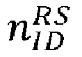
DM-RS Scrambling Identity (for DFT-s-OFDM) {0,1, ..., 65535} dmrsGH Group Hopping {0,1} dmrsSH Sequence Hopping {0,1} DMRS Configuration dmrs-Type DMRS Configuration Type {1,2} maxLength Single Symbol or Double Symbol {1,2} dmrs-TypeA-Position DMRS Start Pos for Type A {pos2, pos3} dmrs-AdditionalPosition Additional DMRS Position {0,1,2,3} p̃ Antenna Port Index {0,1, ...,11} Table 5: An example look-up table for the channel estimation methods Bitfield Channel estimation method 00 LS 01 MMSE 10 DFT based 11 DCT based Table 6: An example look-up table for MMSE channel estimation matrix elements. Bitfield MMSE matrix 000 φ 1 001 φ 2 010 φ 3 011 φ 4 100 φ 5 101 φ 6 110 φ 7 111 φ 8 Table 7: An example look-up table for the channel estimation granularity in the frequency domain. Bitfield CE Granularity in the Frequency Domain [RBs] 00 N 1 01 N 2 10 N 3 11 N 4 Table 8: An example look-up table for window type. Bitfield Window type 00 Type 101 Type 210 Type 311 Type 4Table 9: An example look-up table for window size. Bitfield Window size 00 Window size 101 Window size 210 Window size 311 Window size 4Table 10: Summary of relevant look-up tables for channel estimation. Channel estimation method Relevant look-up table(s) LS Table 5, Table 7 MMSE Table 5, Table 6, Table 7 DFT based Table 5, Table 7, Table 8, Table 9 DCT based Table 5, Table 7, Table 8, Table 9 Table 11: A summary of channel estimation methods and their corresponding details for option 1-2-C (Example-1). Channel estimation method CE Granularity in the Frequency Domain (Integer Values for #RBs) SINR0 (IQ Values) τRMS (IQ Values) Δƒmax (IQ Values) Window type (Indicator for a row in a table) Window size (Integer Values) LS ü - - - - - MMSE ü ü ü ü - - DFT based ü - - - ü ü DCT based ü - - - ü ü Table 12: A summary of channel estimation methods and their corresponding details for option 1-2-C (Example-2). Channel estimation method SINR0 (IQ Values) τRMS (IQ Values) Δfmax (IQ Values) Window type (Indicator for a row in a table) Window size (Integer Values) LS - ü - - - MMSE ü ü ü - - DFT based - ü - ü ü DCT based - ü - ü ü Table 13: A summary of channel estimation methods and their corresponding details for option 1-2-C (Example-3). Channel estimation method SINR0 Values) τRMS Values) Δfmax Values) LS - ü - MMSE ü ü ü DFT based - ü - DCT based - ü - Table 14: A summary of channel estimation methods and their corresponding details for option 1-2-C (Example-4). Channel estimation method τRMS (IQ Values) Δfmax (IQ Values) LS ü - MMSE ü ü DFT based ü - DCT based ü - Table 15: A summary of channel estimation methods and their corresponding details for option 1-2-D. Channel estimation method CE Granularity in the Frequency Domain (Integer Values for #RBs) MMSE matrix (IQ Values) Window type (Indicator for a row in a table) Window size (Integer Values) LS ü - - - MMSE ü ü - - DFT based ü - ü ü DCT based ü - ü ü Table 16: An example look-up table for the combining/digital beamforming matrix calculation methods Bitfield Combining/digital beamforming matrix calculation method 000 Conjugate combining 001 Zero forcing 010 MMSE 011 MMSE- IRC 100 Null-space dimension increase based 101 DFT-compression Table 17: An example look-up table for the channel equalization methods Bitfield Channel equalization method 00 Zero forcing 01 MMSE 10 MMSE- IRC Table 18: An example look-up table for the additional channel equalization information Bitfield Supplementary Demodulation Information Calculation Method 000 Equalization Gain and Post-processed Noise plus Interference Power 001 Post-processed Noise plus Interference Power divided by Equalization Gain 010 Equalization Gain divided by Post-processed Noise plus Interference Power 011 Equalization Gain 100 Post-processed Noise plus Interference Power 101 Channel Estimates and Estimated DM-RS Noise plus Interference Power Table 19: Another example look-up table for the additional channel equalization information Bitfield Supplementary Demodulation Information Calculation Method 00 Equalization Gain and Post-processed Noise plus Interference Power 01 Post-processed Noise plus Interference Power divided by Equalization Gain 10 Equalization Gain 11 Post-processed Noise plus Interference Power - M-plane embodiments for the O-RU to report its capabilities about the supported O-RU categories
- In one embodiment, the O-RU exposes its ability to support category C1, category C2, or category C3 to the SMO or the O-RU controller in the O-RAN module-cap.yang. One example of the RU-supported-category leaf under the RU-capabilities structure in the O-RAN-module-cap.yang can be shown as follows:
 grouping ru-capabilities {
 description
 "Structure representing set of capabilities.";

 leaf ru-supported-category {
 type enumeration {
  enum CAT_A {
   description
    "Informs that precoding is not supported in O-RU";
  }
  enum CAT_B {
   description
    "Informs that precoding is supported in O-RU";
  }
  enum CAT_A_C1 {
   description
    "Informs that precoding is not supported in O-RU for DL and DM-RS based channel
    estimation is supported in the O-RU for UL";
  }
  enum CAT_A_C2 {
   description
    "Informs that precoding is not supported in O-RU for DL and DM-RS based channel
    estimation and equalization are supported in the O-RU for UL ";
  }
  enum CAT_A_C3 {
   description
    "Informs that precoding is not supported in O-RU for DL and DM-RS based channel
    estimation, equalization, and demodulation are supported in the O-RU for UL ";
  }
  enum CAT_B_C1 {
   description
    "Informs that precoding is supported in O-RU for DL and DM-RS based channel
    estimation is supported in the O-RU for UL ";
  }
  enum CAT_B_C2 {
   description
    "Informs that precoding is supported in O-RU for DL and DM-RS based channel
    estimation and equalization are supported in the O-RU for UL ";
  }
  enum CAT_B_C3 {
   description
    "Informs that precoding is supported in O-RU for DL and DM-RS based channel
    estimation, equalization, and demodulation are supported in the O-RU for UL ";
  }
 }

 description
  "Informs about which category O-RU supports";
 }
 feature DMRS-BASED-CHANNEL-ESTIMATION-SUPPORTED {
 description
 "This is used to indicate O-RU's support for demodulation reference signal (DMRS)-based
 channel estimation.";
 }
If feature DMRS-BASED-CHANNEL-ESTIMATION-SUPPORTED is true, the O-RU reports its support for the following dependent features:
- dmrs-based-channel-estimation-configuration-type
- ∘ static-dmrs-based-channel-estimation-configuration-type
- ∘ dynamic-dmrs-based-channel-estimation-configuration-type
- dmrs-generation-method
- ∘ dmrs-local-generation
- ∘ dmrs-sequence-reception
- dmrs-channel-estimation-technique
- ∘ ls-channel-estimation
- ∘ mmse-channel-estimation
- ∘ dft-channel-estimation
- ∘ dct-channel-estimation
- dmrs-channel-estimation-fh-method
- ∘ static-channel-estimation-type-only-indication-method
- ∘ static-full-id-based-channel-estimation-method
- ∘ real-time-channel-estimation-method
- ∘ partial-real-time-channel-estimation-method
- combining-digital-bf-matrix-enhancement-information
- ∘ srs-channel-estimates
- ▪ weighting-coefficients-local-generation
- ▪ weighting-coefficients-reception
- ∘ preliminary-combining-digital-bf-matrix
- ▪ weighting-coefficients-local-generation
- ▪ weighting-coefficients-reception
- ∘ srs-channel-estimates
- combining-matrix-calculation-method
- ∘ conjugate-combining
- ∘ zero-forcing
- ∘ dft-compression
- ∘ null-space-dimension-increase-based
- ∘ mmse-irc-based




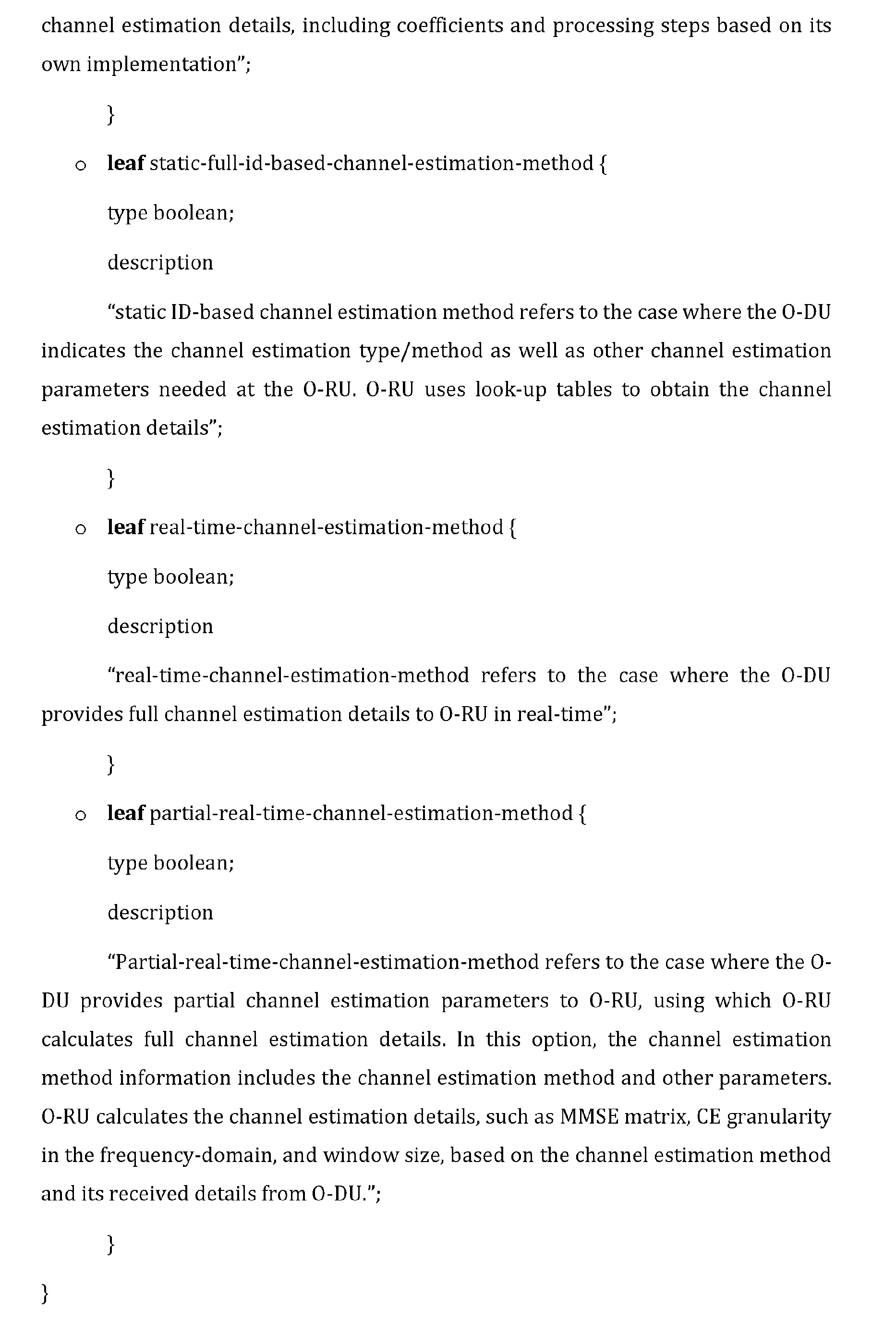


| ef | extType = | 1 | Octet N | ||||||||
| extLen | 1 | N+1 | |||||||||
| TP | scramblinglnit | GH | SH | configType | maxLen | pos | reserved | 1 | N+2 | ||
| scramblingID[15:8] | 1 | N+3 | |||||||||
| scramblingID [7:0] | 1 | N+4 | |||||||||
| addPos[1:0] | antPortInd[3:0] | reserved | 1 | N+5 | |||||||
| zero pad to 4-byte boundary | 1 | N+6 | |||||||||
| zero pad to 4-byte boundary | 1 | N+7 | |||||||||
- Description: This parameter is used to indicate if Transform precoding is enabled or disabled. The default is that transform precoding is disabled.
- Value range: {0b: Disabled; 1b: Enabled}.
- Type: binary bit.
- Field length: 1 bit.
- Default Value: 0
 list dmrs-based-channel-estimation-configuration {
 if-feature mcap: DMRS-BASED-CHANNEL-ESTIMATION-SUPPORTED;
 key dmrs-ce-config-id;
 description
  "List of DMRS-based channel estimation configurations. An O-RU shall reject any
  configuration
  modification which exceed the maximum permitted configurations supported by
  the O-RU";
 leaf dmrs-ce-config-id {
  type uint8;
  description
   "Supplementary parameter acting as key in list of DMRS based channel estimation
   configurations.";
 }
 uses dmrs-based-channel-estimation-configuration; }
 grouping dmrs-based-channel-estimation-configuration {
 description
  "Set of parameters related to DMRS-based channel estimation configuration";
 list dmrs-sequence-generation {
  key dmrs-sequence-id;
  min-elements 1;
  description
   "Provides configuration parameters by the O-RU to generate the DMRS sequence
   locally to be used for channel estimation.";
  leaf dmrs-sequence-id {
   type uint16;
   mandatory true;
   description
    "Supplementary parameter acting as key for dmrs-sequence list."; }
  leaf transform-recoding {
   type boolean{
   }
   mandatory true;
   description
    "This parameter enable or disable transform precoding. True means transform
    precoding is enabled.";
  leaf dmrs-scrambling-id{
   type uint16{
    range 0..65535; }
   mandatory true;
   description
    "DMRS scrambling Identity.";
  }
  leaf dmrs-scrambling-initialization{
   type uint8{
    range 0,1;
   }
   mandatory true;
   description
    "DMRS scrambling initialization"; }
  leaf number-of-ofdm-symbols-in-slot{
   type uint8{
    range 12, 14;
   }
   mandatory true;
   description
    "Number of OFDM symbols per slot"; }
  leaf slot-index-in-radio-frame{
   type uint8{
    range 0..159;
   }
   mandatory true;
   description
    "DMRS slot index in radio frame"; }
  leaf symbol-index-within-slot{
   type uint8{
    range 0..13;
   }
   mandatory true;
   description
    "Symbol index within a slot"; }
  leaf dmrs-group-hopping{
   type uint8{
    range 0,1;
   }
   mandatory true;
   description
    "DMRS group hopping"; }
  leaf dmrs-sequence-hopping{
   type uint8{
    range 0,1;
   }
   mandatory true;
   description
    "DMRS sequence hopping"; }
  leaf dmrs-configuration-type{
   type uint8{
    range 1,2;
   }
   mandatory true;
   description
    "DMRS configuration type"; }
  leaf dmrs-max-length{
   type uint8{
    range 1,2;
   }
   mandatory true;
   description
    "DMRS maximum length: Single symbol or double symbol"; }
  leaf dmrs-typeA-position{
   type uint8{
    range 2,3;
   }
   mandatory true;
   description
    "DMRS TypeA position: DMRS start position for Type A. 2 refers to pos2 and 3 refers
    to pos3";
  }
  leaf additional-dmrs-position{
   type uint8{
    range 0,1,2,3;
   }
   mandatory true;
   description
    "Additional DMRS position";
  }
| ef | extType = | 1 | Octet N | |
| extLen | 1 | N+1 | ||
| re | startRec (4 bits) | reserved | ||
| udCompHdr (not always present) | 1 | N+2 | ||
| reserved (not always present) | ||||
| udCompLen (not always present) | ||||
| udCompParam (not always present) | ||||
| iSample (1st RE in the PRB) | 1 | N+3 | ||
| qSample (1st RE in the PRB) | 1 | N+4 | ||
| ... | 1 | N+5 | ||
| iSample (12th RE in the PRB) | ||||
| qSample (12th RE in the PRB) | ||||
| udCompParam (not always present) | ||||
| iSample (1st RE in the PRB) | ||||
| qSample (1st RE in the PRB) | ||||
| ... | 1 | N+6 | ||
| iSample (12th RE in the PRB) | 1 | N+7 | ||
| qSample (12th RE in the PRB) | ||||
- Description: This parameter is used to indicate if every RE is used or every other RE is used. The starting RE is defined by startRec
- Value range: {0b=every RE used; 1b=every other RE used}.
- Type: binary bit.
- Field length: 1 bit.
- Default Value: 0b (every RE used)
- startRec (start RE)
- Description: This parameter is used to indicate the first RE within a PRB.
- Value range: {0 -11}.
- Type: uint.
- Field length: 4 bits.
- Default Value: 0
| ef | extType = | 1 | Octet N | |||
| extLen | 1 | N+1 | ||||
| chEstMeth | mmseMatrixId | chEstGranularity | 1 | N+2 | ||
| windowType | windowSize | reserved | 1 | N+3 | ||
- Description: This parameter is used to indicate the channel estimation method. The default is the LS method..
- Value range: {00b: LS; 01b: MMSE; 10b: DFT based; 11b: DCT based}.
- Type: unsigned integer.
- Field length: 2 bits.
- Default Value: 00
- Description: This parameter is used to indicate the channel estimation matrix ID. This field is feasible only if the chEstMeth = 00b (i.e., LS channel estimation). For other channel estimation methods, the O-DU shall set this field to the default value and the O-RU shall ignore this field.
- Value range: {000b: φ 1 - 111b: φ 8}.
- Type: unsigned integer.
- Field length: 3 bits.
- Default Value: 000
- Description: This parameter is used to indicate the channel estimation granularity in the frequency domain.
- Value range: {00b: N 1; 01b: N 2; 10b: N 3; 11b: N 4}.
- Type: unsigned integer.
- Field length: 2 bits.
- Default Value: 00
- Description: This parameter is used to indicate the channel estimation window type. This field is feasible only if the chEstMeth = 10b or 11b(i.e., DFT or DCT based channel estimation). For other channel estimation methods, the O-DU shall set this field to the default value and the O-RU shall ignore this field.
- Value range: {00b:
Type 1; 01b:Type 2; 10b:Type 3; 11b: Type 4}. - Type: unsigned integer.
- Field length: 2 bits.
- Default Value: 00
- Description: This parameter is used to indicate the channel estimation window size. This field is feasible only if the chEstMeth = 10b or 11b(i.e., DFT or DCT based channel estimation). For other channel estimation methods, the O-DU shall set this field to the default value and the O-RU shall ignore this field.
- Value range: {00b:
Size 1; 01b:Size 2; 10b:Size 3; 11b: Size 4}. - Type: unsigned integer.
- Field length: 2 bits.
- Default Value: 00


- 1) When MZC ≥ 36:


The length NZC is defined as the largest prime number, which is less than the base sequence length MZC. - 2) When MZC ∈ {6,12,18,24}:

- 3) When MZC = 30:



- 1) When neither group nor sequence hopping is enabled:

- 2) When group hopping is enabled:


- 3) When sequence hopping is enabled:

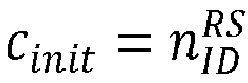


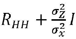












- a) Equalization Gain and Post-processed Noise plus Interference Power (i.e., after equalization operation)
- b ) Post-processed Noise plus Interference Power divided by Equalization Gain
- c ) Equalization Gain divided by Post-processed Noise plus Interference Power

- a) Conjugate combining: In this method, the combining/digital beamforming matrix is calculated using HH.
- b) Zero forcing: In this method, the combining/digital beamforming matrix is calculated using (HHH)-1 HH.
- c) MMSE: In this method, the combining/digital beamforming matrix can be calculated in two alternative forms:


- d) MMSE-IRC: In this method, the combining/digital beamforming matrix is calculated using HH (HHH + Rnn )-1 where Rnn the covariance matrix of interference plus noise.
- e) Null-space dimension increase based: In this method, the singular-value decomposition (SVD) of the channel subspace of the desired UEs and the intra-site interfering UEs, if any, is first calculated, and its null-space is characterized. A sufficient number N of singular vector(s) are selected in the null-space so that N + NUE = L where L is the total number of streams to be transferred from RU to DU. Then, the combining/digital beamforming matrix is constructed as a vertical concatenation of HH and the selected singular vectors.
- f) DFT compression: In this method, the energy of each row of W × H is calculated and sorted in decreasing order of energy, where W is the two-dimensional Discrete-Fourier Transform (DFT) matrix. Then, the combining/digital beamforming matrix is constructed as the L rows of W which correspond to the first L rows in the sorted list, where L is the total number of streams to be transferred from RU to DU.
- 1. An Open Radio Access Network (O-RAN) system, comprising:
- a baseband unit (BBU) having an O-RAN centralized unit (O-CU) and an O-RAN distributed unit (O-DU);
- an O-RAN radio unit (O-RU) remote from the BBU; and
- a fronthaul interface between the O-RU and the BBU;
- wherein a functional split of O-RAN functions respectively assigned to O-RU and O-DU for the fronthaul interface between the BBU and the O-RU is different for downlink (DL) and uplink (UL), and wherein at least one of i) demodulation reference signal (DM-RS)-based channel estimation is performed by the O-DU in the DL and by the O-RU in the UL, ii) equalization is performed by the O-DU in the DL and by the O-RU in the UL, and iii) demodulation is performed by the O-DU in the DL and by the O-RU in the UL.
- 2. The system according to the
above point 1, wherein the O-DU transfer DM-RS information to the O-RU, the DM-RS information including DM-RS configuration parameters of the scheduled or paired UEs/layers are received by the O-RU, and the O-RU generates a DM-RS sequence using the DM-RS configuration parameters received from O-DU. - 3. The system according to the
above point 2, wherein the O-DU transfers DM-RS channel estimation method information to the O-RU to indicate a channel estimation method. - 4. The system according to the
above point 3, wherein the O-DU indicates a combining/digital beamforming matrix calculation method to the O-RU. - 5. The system according to the
above point 2, wherein the O-DU transfers a combining/digital beamforming matrix enhancement information to the O-RU. - 6. The system according to the above point 5, wherein the O-DU indicates a combining/digital beamforming matrix calculation method to the O-RU.
- 7. The system according to the
above point 2, wherein the O-RU estimates the UL channels of the UE(s) and/or layer(s) transmitted at a current slot n using the DM-RS information. - 8. The system according to the
above point 7, wherein the O-DU indicates a combining/digital beamforming matrix calculation method to the O-RU. - 9. The system according to the
above point 7,wherein the O-RU calculates the combining/digital beamforming matrix. - 10. The system according to the
above point 9,wherein the O-RU applies the calculated combining/digital beamforming matrix to a received signal and transfers the calculated combining/digital beamforming matrix to the O-DU. - 11. The system according to the
above point 9,wherein O-DU performs a L1/L2 processing on the resulting signal. - 12. The system according to the
above point 1, wherein i) a demodulation reference signal (DM-RS)-based channel estimation is performed by the O-DU in the DL and by the O-RU in the UL, and ii) an equalization is performed by the O-DU in the DL and by the O-RU in the UL. - 13. The system according to the
above point 12, wherein the O-DU transfer DM-RS information to the O-RU, the DM-RS information including DM-RS configuration parameters of the scheduled or paired UEs/layers are received by the O-RU, and the O-RU generates a DM-RS sequence using the DM-RS configuration parameters received from O-DU. - 14. The system according to the
above point 13, wherein the O-RU estimates the UL channels of the UE(s) and/or layer(s) transmitted at a current slot n using the DM-RS information. - 15. The system according to the
above point 14, wherein, prior to the estimation the UL channels of the UE(s) and/or layer(s) transmitted at a current slot n using the DM-RS information, the O-DU indicates ta DM-RS channel estimation method information to the O-RU. - 16. The system according to the
above point 15, wherein the O-DU transfers DM-RS channel estimation method information to the O-RU to indicate the channel estimation method. - 17. The system according to the
above point 14,wherein the O-RU equalizes the UL channels of the one or more UEs, the one or more layers, or both transmitted at a current slot n. - 18. The system according to the
above point 17,wherein the O-RU calculates a supplementary demodulation information and transfers the supplementary demodulation information along with an equalized signal stream to the O-DU. - 19. The system according to the
above point 18,wherein O-DU performs a demodulation on a signal of slot n transferred from the O-RU and a L1/L2 processing on the demodulated signal. - 20. The system according to the
above point 1, wherein i) a demodulation reference signal (DM-RS)-based channel estimation is performed by the O-DU in the DL and by the O-RU in the UL, ii) an equalization is performed by the O-DU in the DL and by the O-RU in the UL, and iii) demodulation is performed by the O-DU in the DL and by the O-RU in the UL. - 21. The system according to the above point 20, wherein the O-DU transfer DM-RS information to the O-RU, the DM-RS information including DM-RS configuration parameters of the scheduled or paired UEs/layers are received by the O-RU, and the O-RU generates a DM-RS sequence using the DM-RS configuration parameters received from O-DU.
- 22. The system according to the above point 21, wherein the O-RU estimates the UL channels of the UE(s) and/or layer(s) transmitted at a current slot n using the DM-RS information.
- 23. The system according to the above point 22, wherein, prior to the estimation the UL channels of the UE(s) and/or layer(s) transmitted at a current slot n using the DM-RS information, the O-DU indicates ta DM-RS channel estimation method information to the O-RU.
- 24. The system according to the above point 23, wherein the O-DU transfers DM-RS channel estimation method information to the O-RU to indicate the channel estimation method.
- 25. The system according to the above point 22,wherein the O-RU equalizes the UL channels of the one or more UEs, the one or more layers, or both, transmitted at a current slot n.
- 26. The system according to the above point 25,wherein, prior to a slot n, the DU transfers modulation information to the RU and the O-RU performs demodulation on an equalized signal.
- 27. The system according to the
above point 26,wherein O-DU performs a descrambling operation on the equalized signal of slot n transferred from the O-RU and a L1/L2 processing on the descrambled signal. - 28. The system according to the
above point 1, wherein i) a demodulation reference signal (DM-RS)-based channel estimation is performed by the O-DU in the DL and by the O-RU in the UL, ii) an equalization is performed by the O-DU in the DL and by the O-RU in the UL, and iii) demodulation is performed by the O-DU in the DL and by the O-RU in the UL. - 29. According to the present invention, it is further provided a method of operating an Open Radio Access Network (O-RAN) system, comprising:
- providing a baseband unit (BBU) having an O-RAN centralized unit (O-CU) and an O-RAN distributed unit (O-DU);
- providing an O-RAN radio unit (O-RU) remote from the BBU; and
- providing a fronthaul interface between the O-RU and the BBU;
- wherein a functional split of O-RAN functions respectively assigned to O-RU and O-DU for the fronthaul interface between the BBU and the O-RU is different for downlink (DL) and uplink (UL), and wherein at least one of i) demodulation reference signal (DM-RS)-based channel estimation is performed by the O-DU in the DL and by the O-RU in the UL, ii) equalization is performed by the O-DU in the DL and by the O-RU in the UL, and iii) demodulation is performed by the O-DU in the DL and by the O-RU in the UL.
- 30. The method according to the above point 29, wherein i) demodulation reference signal (DM-RS)-based channel estimation is performed by the O-DU in the DL and by the O-RU in the UL, and ii) equalization is performed by the O-DU in the DL and by the O-RU in the UL.
- 31. The method according to the above point 29, wherein i) demodulation reference signal (DM-RS)-based channel estimation is performed by the O-DU in the DL and by the O-RU in the UL, ii) equalization is performed by the O-DU in the DL and by the O-RU in the UL, and iii) demodulation is performed by the O-DU in the DL and by the O-RU in the UL.
- 32. According to the present invention, it is further provided a method demodulation reference signal (DM-RS)-based channel estimation is performed by the O-RU in an OFDM system with N subcarriers, comprising at least one of:
- a Least-Squares (LS) Channel Estimation;
- a Minimum Mean-Square Error (MMSE) Channel Estimation;
- a Discrete Fourier Transform (DFT) based Channel Estimation; or
- a Discrete Cosine Transform (DCT) based Channel Estimation,

- 33. The method of the above point 32, further comprising:
after extracting DM-RS symbols of the received DM-RS signal in the frequency domain, the LS channel estimation is:
and de-spreading the channel estimation as:
- 34. The method of the above point 32, further comprising:
the MMSE channel estimation being calculated as follows:
- 35. The method of the above point 32, further comprising:
the DFT channel estimation being calculated as follows:- calculating the LS channel estimate (ĤLS ) or an MMSE channel estimate as an initial estimate;
- converting the LS channel estimate or MMSE channel estimate to a time domain with an IDFT operation:

- filtering noise outside maximum delay of the channel:

- 36. The method of the above point 32, further comprising:
the DCT channel estimation being calculated as follows:- calculating the LS channel estimate (ĤLS ) or the MMSE estimate as an initial estimate;
- converting the LS or MMSE estimate to a transform domain with a DCT operation:

- filtering noise outside maximum delay of the channel:

- ∘ 3GPP: Third generation partnership project
- o BS: Base Station
- o CA: Carrier Aggregation
- o CAPEX: Capital Expenditure
- o CBRS: Citizens Broadband Radio Services
- o CC: Component carrier
- o COTS: Commercial off-the-shelf
- o CP: cyclic prefix
- o C-plane: Control plane
- o C-RAN: cloud radio access network
- o CU: Central unit
- o DCI: downlink control indicator
- o DL: downlink
- o DU: Distribution unit
- ∘ eAxC ID: Extended Antenna-Carrier identifier: a data flow for a single antenna (or spatial stream) for a single carrier in a single sector.
- ∘ eNB: Evolved Node B (applies to LTE)
- ∘ FDD: Frequency-division duplex
- ∘ FEC: forward error correction
- ∘ FH: Fronthaul
- ∘ FFT: Fast Fourier Transform
- ∘ gNB: g NodeB (applies to NR)
- ∘ iFFT: inverse Fast Fourier Transform
- ∘ HARQ: hybrid automatic repeat request
- ∘ LTE: long term evolution
- ∘ LTE-A: LTE Advanced
- ∘ M-plane: Management plane
- ∘ MCS: modulation and coding scheme
- ∘ MIMO: multiple input, multiple output
- ∘ MMSE-IRC: Minimum mean square error - interference rejection combining
- ∘ MMSE-MRC: Minimum mean square error - maximum-ratio combining
- ∘ mmWave: millimeter wave
- ∘ MNO: Mobile network operator
- ∘ NR: New radio
- ∘ OAM: Operation and management
- ∘ O-DU: O-RAN Distributed Unit
- ∘ O-RU: O-RAN Radio Unit
- ∘ O-RAN: Open RAN (Basic O-RAN specifications are prepared by the O-RAN alliance)
- ∘ OPEX: Operating Expense
- ∘ PBCH: Physical Broadcast Channel
- ∘ PCFICH: Physical Control Format Indicator Channel
- ∘ PDCCH: Physical downlink Control Channel
- ∘ PDCP: Packet Data Convergence Protocol
- ∘ PDSCH: physical downlink shared channel
- ∘ PHICH: Physical Hybrid ARQ Indicator Channel
- ∘ PHY: physical layer
- ∘ LPHY: lower physical layer
- ∘ UPHY: upper physical layer
- ∘ PUCCH: Physical Uplink Control Channel
- ∘ PUSCH: Physical Uplink Shared Channel
- ∘ QAM: quadrature amplitude modulation
- ∘ QPSK: Quadrature Phase Shift Keying
- ∘ RACH: random access channel
- ∘ PRACH: physical random access channel
- ∘ RF: radio frequency interface
- ∘ RLC: Radio Link Control
- ∘ RRC: Radio Resource Control
- ∘ RRM: Radio resource management
- ∘ RRU: Remote radio unit
- ∘ RU: Radio Unit
- ∘ RS: reference signal
- ∘ RSSI: received signal strength indicator
- ∘ RPC: Remote procedure call
- ∘ SMO: Service Management and Orchestration
- ∘ S-plane: Synchronization plane
- ∘ SCell: Secondary cell
- ∘ SIMO: single input, multiple output
- ∘ SINR: signal-to-interference-plus-noise ratio
- ∘ SRS: Sounding reference signal
- ∘ SSS: Secondary Synchronization Signal
- ∘ TB: transport block
- ∘ TTI: Transmission Time Interval
- ∘ TDD: Time division duplex
- ∘ U-plane: User plane
- ∘ UCI: Uplink Control Information
- ∘ UE: user equipment
- ∘ UL: uplink
- ∘ UL DMRS: uplink demodulation reference signal
- ∘ ULSCH: Uplink Shared Channel
- ∘ vBBU: Virtualized baseband unit
- ∘ VNF: Virtual Network Function
- ORAN-WG4.MP.0-v06.00: O-RAN Fronthaul Working Group Management Plane Specification, Release 06.00.
- ORAN-WG4.CUS-plane.0-v06.00: O-RAN Fronthaul Working Group Control, User, and Synchronization Plane Specification, Release 06.00.
Claims (15)
- An Open Radio Access Network, O-RAN, system, comprising:a baseband unit, BBU, having an O-RAN centralized unit, O-CU, and an O-RAN distributed unit, O-DU;an O-RAN radio unit, O-RU, remote from the BBU; anda fronthaul interface between the O-RU and the BBU;wherein a functional split of O-RAN functions respectively assigned to O-RU and O-DU for the fronthaul interface between the BBU and the O-RU is different for downlink, DL, and uplink, UL, and wherein at least one of i) demodulation reference signal, DM-RS,-based channel estimation is performed by the O-DU in the DL and by the O-RU in the UL, ii) equalization is performed by the O-DU in the DL and by the O-RU in the UL, and iii) demodulation is performed by the O-DU in the DL and by the O-RU in the UL.
- The system according to claim 1, wherein the O-DU transfer DM-RS information to the O-RU, the DM-RS information including DM-RS configuration parameters of the scheduled or paired UEs/layers are received by the O-RU, and the O-RU generates a DM-RS sequence using the DM-RS configuration parameters received from O-DU.
- The system according to claim 2, wherein the O-DU transfers DM-RS channel estimation method information to the O-RU to indicate a channel estimation method, and wherein the O-DU indicates a combining/digital beamforming matrix calculation method to the O-RU.
- The system according to claim 2, wherein the O-DU transfers a combining/digital beamforming matrix enhancement information to the O-RU, and, wherein the O-DU indicates a combining/digital beamforming matrix calculation method to the O-RU.
- The system according to claim 2, wherein the O-RU estimates the UL channels of the UE(s) and/or layer(s) transmitted at a current slot n using the DM-RS information, and wherein the O-DU indicates a combining/digital beamforming matrix calculation method to the O-RU.
- The system according to claim 5, wherein the O-RU calculates the combining/digital beamforming matrix and wherein the O-RU applies the calculated combining/digital beamforming matrix to a received signal and transfers the calculated combining/digital beamforming matrix to the O-DU.
- The system according to claim 1, wherein i) a demodulation reference signal, DM-RS,- based channel estimation is performed by the O-DU in the DL and by the O-RU in the UL, and ii) an equalization is performed by the O-DU in the DL and by the O-RU in the UL.
- The system according to claim 7, wherein the O-DU transfer DM-RS information to the O-RU, the DM-RS information including DM-RS configuration parameters of the scheduled or paired UEs/layers are received by the O-RU, and the O-RU generates a DM-RS sequence using the DM-RS configuration parameters received from O-DU, and wherein the O-RU estimates the UL channels of the UE(s) and/or layer(s) transmitted at a current slot n using the DM-RS information.
- The system according to claim 8, wherein the O-RU equalizes the UL channels of the one or more UEs, the one or more layers, or both transmitted at a current slot n.
- The system according to claim 9, wherein the O-RU calculates a supplementary demodulation information and transfers the supplementary demodulation information along with an equalized signal stream to the O-DU.
- The system according to claim 10, wherein O-DU performs a demodulation on a signal of slot n transferred from the O-RU and a L1/L2 processing on the demodulated signal.
- The system according to claim 7, wherein iii) demodulation is performed by the O-DU in the DL and by the O-RU in the UL.
- The system according to claim 12, wherein the O-DU transfer DM-RS information to the O-RU, the DM-RS information including DM-RS configuration parameters of the scheduled or paired UEs/layers are received by the O-RU, and the O-RU generates a DM-RS sequence using the DM-RS configuration parameters received from O-DU.
- The system according to claim 13, wherein the O-RU estimates the UL channels of the UE(s) and/or layer(s) transmitted at a current slot n using the DM-RS information, and wherein, prior to the estimation the UL channels of the UE(s) and/or layer(s) transmitted at a current slot n using the DM-RS information, the O-DU indicates ta DM-RS channel estimation method information to the O-RU.
- A method of operating an Open Radio Access Network, O-RAN, system, comprising:providing a baseband unit, BBU, having an O-RAN centralized unit, O-CU, and an O-RAN distributed unit, O-DU;providing an O-RAN radio unit, O-RU, remote from the BBU; andproviding a fronthaul interface between the O-RU and the BBU;wherein a functional split of O-RAN functions respectively assigned to O-RU and O-DU for the fronthaul interface between the BBU and the O-RU is different for downlink, DL, and uplink, UL, and wherein at least one of i) demodulation reference signal, DM-RS,-based channel estimation is performed by the O-DU in the DL and by the O-RU in the UL, ii) equalization is performed by the O-DU in the DL and by the O-RU in the UL, and iii) demodulation is performed by the O-DU in the DL and by the O-RU in the UL.
Applications Claiming Priority (3)
| Application Number | Priority Date | Filing Date | Title |
|---|---|---|---|
| US202163244774P | 2021-09-16 | 2021-09-16 | |
| US202163257811P | 2021-10-20 | 2021-10-20 | |
| US202263300108P | 2022-01-17 | 2022-01-17 |
Publications (1)
| Publication Number | Publication Date |
|---|---|
| EP4152639A1 true EP4152639A1 (en) | 2023-03-22 |
Family
ID=83361187
Family Applications (1)
| Application Number | Title | Priority Date | Filing Date |
|---|---|---|---|
| EP22196116.2A Pending EP4152639A1 (en) | 2021-09-16 | 2022-09-16 | Systems and methods for enhancing efficient uplink mimo performance and implementation for o-ran-based radio access networks |
Country Status (2)
| Country | Link |
|---|---|
| US (1) | US12627529B2 (en) |
| EP (1) | EP4152639A1 (en) |
Cited By (5)
| Publication number | Priority date | Publication date | Assignee | Title |
|---|---|---|---|---|
| WO2024209375A1 (en) * | 2023-04-04 | 2024-10-10 | Telefonaktiebolaget Lm Ericsson (Publ) | An improved uplink lower layer split supporting advanced comp |
| WO2024219714A1 (en) * | 2023-04-19 | 2024-10-24 | 삼성전자주식회사 | Device and method for processing uplink reference signal within fronthaul interface |
| US20250141503A1 (en) * | 2023-10-27 | 2025-05-01 | Rakuten Symphony, Inc. | Transmitted precoding matrix indicator (tpmi) determination for new radio (nr) fr1 single user (su) multiple input multiple output (mimo) in an uplink |
| WO2025221200A1 (en) * | 2024-04-17 | 2025-10-23 | Telefonaktiebolaget Lm Ericsson (Publ) | Method to avoid scaling errors of iq samples on fronthaul |
| US20260012272A1 (en) * | 2024-07-05 | 2026-01-08 | Qualcomm Incorporated | Techniques for post-processing signal-to-interference-plus-noise ratio signaling for communication adaptation |
Families Citing this family (23)
| Publication number | Priority date | Publication date | Assignee | Title |
|---|---|---|---|---|
| JP7762357B2 (en) * | 2021-09-03 | 2025-10-30 | 日本電気株式会社 | Radio receiving device and method |
| EP4413666A1 (en) * | 2021-10-07 | 2024-08-14 | TELEFONAKTIEBOLAGET LM ERICSSON (publ) | Uplink interference rejection combining (irc) split in lower-layer split |
| US20250023760A1 (en) * | 2021-11-23 | 2025-01-16 | Telefonaktiebolaget Lm Ericsson (Publ) | Network node and user equipment for estimation of a radio propagation channel |
| DE112023001123T5 (en) * | 2022-02-27 | 2024-12-05 | Maxlinear, Inc. | BEAMFORMING ESTIMATION |
| US11956041B2 (en) * | 2022-04-22 | 2024-04-09 | At&T Intellectual Property I, L.P. | Massive multiple-input-multiple-output (MIMO) uplink enhancement in split radio access network (RAN) deployments |
| US12501437B2 (en) * | 2022-09-16 | 2025-12-16 | Qualcomm Incorporated | Channel correlation report for improving channel prediction |
| US11838169B1 (en) * | 2022-09-30 | 2023-12-05 | Dell Products L.P. | Remote logging management in multi-vendor O-RAN networks |
| WO2024112333A1 (en) * | 2022-11-23 | 2024-05-30 | Altiostar Networks, Inc. | Sounding reference signal beamformer enhancement with timing correction |
| US20240291550A1 (en) * | 2023-02-24 | 2024-08-29 | Samsung Electronics Co., Ltd. | Spatial combining of ul in mimo systems |
| EP4717003A1 (en) * | 2023-05-23 | 2026-04-01 | Telefonaktiebolaget LM Ericsson (publ) | Improved lower layer split for closed loop power control |
| US20250031067A1 (en) * | 2023-07-21 | 2025-01-23 | Mavenir Systems, Inc. | Systems and Methods for Energy and Fronthaul Bandwidth Efficient Uplink Performance Improvements for O-RAN-based Radio Access Networks |
| US12549304B2 (en) * | 2023-10-16 | 2026-02-10 | At&T Intellectual Property I, L.P. | Architecture and signaling to enhance uplink processing in split radio access network (RAN) deployments |
| EP4554131A1 (en) * | 2023-11-08 | 2025-05-14 | INTEL Corporation | Remote unit (ru) and distributed unit (du) alignment for performance interoperability |
| WO2025127166A1 (en) * | 2023-12-11 | 2025-06-19 | 삼성전자 주식회사 | Singular value decomposition (svd)-based port combining signaling method and device in communication system |
| US20250233708A1 (en) * | 2024-01-16 | 2025-07-17 | Dell Products L.P. | Radio access network splits for reduced radio unit complexity |
| EP4646901B1 (en) * | 2024-01-29 | 2026-05-13 | Telefonaktiebolaget LM Ericsson (publ) | Signal-to-interference-plus-noise ratio report for open radio access network open fronthaul interface |
| WO2025192872A1 (en) * | 2024-03-12 | 2025-09-18 | 삼성전자주식회사 | Apparatus and method for managing state of apparatus on basis of control signal |
| WO2025212472A1 (en) * | 2024-04-03 | 2025-10-09 | Rakuten Mobile, Inc. | Dual mode o-ru operations for energy efficiency and resource sharing |
| WO2025250075A1 (en) * | 2024-05-31 | 2025-12-04 | Telefonaktiebolaget Lm Ericsson (Publ) | Efficient sinr report for o-ran open fronthaul interface |
| WO2026014969A1 (en) * | 2024-07-12 | 2026-01-15 | Samsung Electronics Co., Ltd. | System and method for transmitting a demodulation reference signal (dmrs) sequence to user equipment |
| WO2026089424A1 (en) * | 2024-10-21 | 2026-04-30 | 삼성전자 주식회사 | Method and device for transmitting and utilizing tpmi information of terminal in o-ran-based system |
| CN122317929A (en) * | 2024-12-27 | 2026-06-30 | 北京三星通信技术研究有限公司 | Methods and apparatus performed by nodes in a wireless communication system |
| WO2025236749A1 (en) * | 2025-01-21 | 2025-11-20 | Lenovo (Beijing) Limited | Methods and apparatuses for a sounding reference signal (srs) based radio resource management (rrm) measurement in a lower layer split (lls) radio access network (ran) |
Citations (1)
| Publication number | Priority date | Publication date | Assignee | Title |
|---|---|---|---|---|
| US20200235788A1 (en) * | 2017-07-31 | 2020-07-23 | Mavenir Networks, Inc. | Method and apparatus for flexible fronthaul physical layer split for cloud radio access networks |
Family Cites Families (7)
| Publication number | Priority date | Publication date | Assignee | Title |
|---|---|---|---|---|
| JPWO2017175606A1 (en) * | 2016-04-08 | 2019-02-14 | 株式会社Nttドコモ | Method of interface between central concentrator and extension device and wireless network control system |
| KR102821713B1 (en) * | 2019-02-12 | 2025-06-18 | 삼성전자 주식회사 | Apparatus and method for trasmitting signals using fronthaul in communication system |
| EP3817487B1 (en) * | 2019-11-04 | 2024-11-20 | Nokia Solutions and Networks Oy | Radio mac scheduling based on front-haul transport capacity constraints |
| EP4096318B1 (en) * | 2020-02-14 | 2025-10-22 | Huawei Technologies Co., Ltd. | Resource configuration method and network device |
| EP3989630A1 (en) * | 2020-10-20 | 2022-04-27 | Fujitsu Limited | A method in a telecommunications system, a telecommunications system, a user equipment and a base station and methods therein for interacting application execution with radio parameters |
| US11489568B2 (en) * | 2020-10-26 | 2022-11-01 | Wisig Networks Private Limited | Method of signal processing by a massive MIMO base station receiver |
| KR20220114968A (en) * | 2021-02-09 | 2022-08-17 | 삼성전자주식회사 | Apparatus and method for spectrum sharing in wireless communication system |
-
2022
- 2022-09-16 EP EP22196116.2A patent/EP4152639A1/en active Pending
- 2022-09-16 US US17/946,516 patent/US12627529B2/en active Active
Patent Citations (1)
| Publication number | Priority date | Publication date | Assignee | Title |
|---|---|---|---|---|
| US20200235788A1 (en) * | 2017-07-31 | 2020-07-23 | Mavenir Networks, Inc. | Method and apparatus for flexible fronthaul physical layer split for cloud radio access networks |
Non-Patent Citations (3)
| Title |
|---|
| CHANG WENTING ET AL: "A Prefiltering C-RAN Architecture with Compressed Link Data Rate in Massive MIMO", 2016 IEEE 83RD VEHICULAR TECHNOLOGY CONFERENCE (VTC SPRING), IEEE, 15 May 2016 (2016-05-15), pages 1 - 6, XP032920014, DOI: 10.1109/VTCSPRING.2016.7504095 * |
| CHIH-LIN I ET AL: "NGFI, the xHaul", 2015 IEEE GLOBECOM WORKSHOPS (GC WKSHPS), IEEE, 6 December 2015 (2015-12-06), pages 1 - 6, XP032871175, DOI: 10.1109/GLOCOMW.2015.7414147 * |
| VARIOUS: "O-RAN Acceleration Abstraction Layer General Aspects and Principles v01.01", 4 March 2021 (2021-03-04), pages 1 - 55, XP055958250, Retrieved from the Internet <URL:O-RAN Alliance e.V.> [retrieved on 20220906] * |
Cited By (8)
| Publication number | Priority date | Publication date | Assignee | Title |
|---|---|---|---|---|
| WO2024209375A1 (en) * | 2023-04-04 | 2024-10-10 | Telefonaktiebolaget Lm Ericsson (Publ) | An improved uplink lower layer split supporting advanced comp |
| WO2024219714A1 (en) * | 2023-04-19 | 2024-10-24 | 삼성전자주식회사 | Device and method for processing uplink reference signal within fronthaul interface |
| EP4694096A4 (en) * | 2023-04-19 | 2026-07-15 | Samsung Electronics Co Ltd | DEVICE AND METHOD FOR PROCESSING AN UPLINK REFERENCE SIGNAL IN A FRONT INTERFACE |
| US20250141503A1 (en) * | 2023-10-27 | 2025-05-01 | Rakuten Symphony, Inc. | Transmitted precoding matrix indicator (tpmi) determination for new radio (nr) fr1 single user (su) multiple input multiple output (mimo) in an uplink |
| US12700896B2 (en) * | 2023-10-27 | 2026-08-04 | Rakuten Symphony, Inc. | Transmitted precoding matrix indicator (TPMI) determination for new radio (NR) frequency range 1 (FRI) single user (SU) multiple input multiple output (MIMO) in an uplink |
| WO2025221200A1 (en) * | 2024-04-17 | 2025-10-23 | Telefonaktiebolaget Lm Ericsson (Publ) | Method to avoid scaling errors of iq samples on fronthaul |
| US20260012272A1 (en) * | 2024-07-05 | 2026-01-08 | Qualcomm Incorporated | Techniques for post-processing signal-to-interference-plus-noise ratio signaling for communication adaptation |
| US12652115B2 (en) * | 2024-07-05 | 2026-06-09 | Qualcomm Incorporated | Techniques for post-processing signal-to-interference-plus-noise ratio signaling for communication adaptation |
Also Published As
| Publication number | Publication date |
|---|---|
| US12627529B2 (en) | 2026-05-12 |
| US20230155864A1 (en) | 2023-05-18 |
Similar Documents
| Publication | Publication Date | Title |
|---|---|---|
| US12627529B2 (en) | Systems and methods for enhancing efficient uplink MIMO performance and implementation for O-RAN-based radio access networks | |
| US11838158B2 (en) | Method and apparatus for configuring demodulation reference signal position in wireless cellular communication system | |
| CN109891818B (en) | Method and device for transmitting/receiving reference signal in wireless communication system | |
| US20100103949A1 (en) | Method of allocating reference signals in mimo system | |
| CN110169002A (en) | The method and device thereof of reference signal are sent in wireless communication system | |
| US20160380689A1 (en) | Method and apparatus of signal transmission and reception in a filter bank multiple carrier system | |
| JP2021044598A (en) | Base station equipment, terminal equipment and communication methods | |
| US11050502B2 (en) | Method and apparatus for network assisted interference cancellation and suppression in wireless cellular communication system | |
| CN108293251A (en) | Systems and methods for transmission and reception of control and data channels utilizing group reference signals | |
| EP2929636A1 (en) | Method for changing pattern of reference signals according to coherence time variation in wireless communication system and apparatus therefor | |
| US12451937B2 (en) | Data based precoding techniques | |
| EP4451629A1 (en) | On-demand ndm dmrs for o-ran-based radio access networks | |
| EP4496237A1 (en) | Systems and methods for energy and fronthaul bandwidth efficient uplink performance improvements for o-ran-based radio access networks | |
| WO2022077142A1 (en) | Method for sending physical uplink shared channel and communication apparatus | |
| EP4712396A1 (en) | Method and apparatus for node used for wireless communication | |
| US20240098704A1 (en) | MAC Architectures for Adaptive NOMA Modulation | |
| US20260074929A1 (en) | Dynamic communication scheme switching | |
| EP4637088A1 (en) | Electronic device and method for receiving signal in wireless communication system | |
| KR20220137430A (en) | Apparatus and method for uplink demodulation reference signal in wireless communication system | |
| Qi et al. | On the physical layer design for low cost machine type communication in 3GPP LTE | |
| EP4704478A1 (en) | Method and device for node used for wireless communication | |
| EP4533716A1 (en) | Continuous phase modulation in wireless communications | |
| CN113630222B (en) | A method and device used in a node for wireless communication | |
| WO2024170060A1 (en) | Method, apparatus and computer program | |
| EP4618666A1 (en) | Method and apparatus for use in wireless communication node |
Legal Events
| Date | Code | Title | Description |
|---|---|---|---|
| PUAI | Public reference made under article 153(3) epc to a published international application that has entered the european phase |
Free format text: ORIGINAL CODE: 0009012 |
|
| STAA | Information on the status of an ep patent application or granted ep patent |
Free format text: STATUS: THE APPLICATION HAS BEEN PUBLISHED |
|
| AK | Designated contracting states |
Kind code of ref document: A1 Designated state(s): AL AT BE BG CH CY CZ DE DK EE ES FI FR GB GR HR HU IE IS IT LI LT LU LV MC MK MT NL NO PL PT RO RS SE SI SK SM TR |
|
| P01 | Opt-out of the competence of the unified patent court (upc) registered |
Effective date: 20230601 |
|
| STAA | Information on the status of an ep patent application or granted ep patent |
Free format text: STATUS: REQUEST FOR EXAMINATION WAS MADE |
|
| 17P | Request for examination filed |
Effective date: 20230921 |
|
| RBV | Designated contracting states (corrected) |
Designated state(s): AL AT BE BG CH CY CZ DE DK EE ES FI FR GB GR HR HU IE IS IT LI LT LU LV MC MK MT NL NO PL PT RO RS SE SI SK SM TR |
|
| STAA | Information on the status of an ep patent application or granted ep patent |
Free format text: STATUS: EXAMINATION IS IN PROGRESS |
|
| 17Q | First examination report despatched |
Effective date: 20250225 |