EP4152535A1 - Apparatus for applying a sleeve to a cable and method of insertion into a conduit - Google Patents
Apparatus for applying a sleeve to a cable and method of insertion into a conduit Download PDFInfo
- Publication number
- EP4152535A1 EP4152535A1 EP22194727.8A EP22194727A EP4152535A1 EP 4152535 A1 EP4152535 A1 EP 4152535A1 EP 22194727 A EP22194727 A EP 22194727A EP 4152535 A1 EP4152535 A1 EP 4152535A1
- Authority
- EP
- European Patent Office
- Prior art keywords
- cable
- sleeve
- former
- formers
- recess
- Prior art date
- Legal status (The legal status is an assumption and is not a legal conclusion. Google has not performed a legal analysis and makes no representation as to the accuracy of the status listed.)
- Granted
Links
Images






Classifications
-
- H—ELECTRICITY
- H02—GENERATION; CONVERSION OR DISTRIBUTION OF ELECTRIC POWER
- H02G—INSTALLATION OF ELECTRIC CABLES OR LINES, OR OF COMBINED OPTICAL AND ELECTRIC CABLES OR LINES
- H02G1/00—Methods or apparatus specially adapted for installing, maintaining, repairing or dismantling electric cables or lines
- H02G1/06—Methods or apparatus specially adapted for installing, maintaining, repairing or dismantling electric cables or lines for laying cables, e.g. laying apparatus on vehicle
- H02G1/08—Methods or apparatus specially adapted for installing, maintaining, repairing or dismantling electric cables or lines for laying cables, e.g. laying apparatus on vehicle through tubing or conduit, e.g. rod or draw wire for pushing or pulling
-
- H—ELECTRICITY
- H01—ELECTRIC ELEMENTS
- H01B—CABLES; CONDUCTORS; INSULATORS; SELECTION OF MATERIALS FOR THEIR CONDUCTIVE, INSULATING OR DIELECTRIC PROPERTIES
- H01B13/00—Apparatus or processes specially adapted for manufacturing conductors or cables
- H01B13/22—Sheathing; Armouring; Screening; Applying other protective layers
- H01B13/26—Sheathing; Armouring; Screening; Applying other protective layers by winding, braiding or longitudinal lapping
- H01B13/2613—Sheathing; Armouring; Screening; Applying other protective layers by winding, braiding or longitudinal lapping by longitudinal lapping
- H01B13/268—Sheathing; Armouring; Screening; Applying other protective layers by winding, braiding or longitudinal lapping by longitudinal lapping of a non-metallic sheet
-
- H—ELECTRICITY
- H01—ELECTRIC ELEMENTS
- H01B—CABLES; CONDUCTORS; INSULATORS; SELECTION OF MATERIALS FOR THEIR CONDUCTIVE, INSULATING OR DIELECTRIC PROPERTIES
- H01B13/00—Apparatus or processes specially adapted for manufacturing conductors or cables
- H01B13/34—Apparatus or processes specially adapted for manufacturing conductors or cables for marking conductors or cables
- H01B13/344—Apparatus or processes specially adapted for manufacturing conductors or cables for marking conductors or cables by applying sleeves, ferrules, tags, clips, labels or short length strips
-
- H—ELECTRICITY
- H01—ELECTRIC ELEMENTS
- H01R—ELECTRICALLY-CONDUCTIVE CONNECTIONS; STRUCTURAL ASSOCIATIONS OF A PLURALITY OF MUTUALLY-INSULATED ELECTRICAL CONNECTING ELEMENTS; COUPLING DEVICES; CURRENT COLLECTORS
- H01R9/00—Structural associations of a plurality of mutually-insulated electrical connecting elements, e.g. terminal strips or terminal blocks; Terminals or binding posts mounted upon a base or in a case; Bases therefor
- H01R9/03—Connectors arranged to contact a plurality of the conductors of a multiconductor cable, e.g. tapping connections
- H01R9/05—Connectors arranged to contact a plurality of the conductors of a multiconductor cable, e.g. tapping connections for coaxial cables
- H01R9/0518—Connection to outer conductor by crimping or by crimping ferrule
-
- H—ELECTRICITY
- H02—GENERATION; CONVERSION OR DISTRIBUTION OF ELECTRIC POWER
- H02G—INSTALLATION OF ELECTRIC CABLES OR LINES, OR OF COMBINED OPTICAL AND ELECTRIC CABLES OR LINES
- H02G15/00—Cable fittings
- H02G15/08—Cable junctions
- H02G15/10—Cable junctions protected by boxes, e.g. by distribution, connection or junction boxes
- H02G15/113—Boxes split longitudinally in main cable direction
-
- H—ELECTRICITY
- H02—GENERATION; CONVERSION OR DISTRIBUTION OF ELECTRIC POWER
- H02G—INSTALLATION OF ELECTRIC CABLES OR LINES, OR OF COMBINED OPTICAL AND ELECTRIC CABLES OR LINES
- H02G15/00—Cable fittings
- H02G15/08—Cable junctions
- H02G15/18—Cable junctions protected by sleeves, e.g. for communication cable
-
- H—ELECTRICITY
- H02—GENERATION; CONVERSION OR DISTRIBUTION OF ELECTRIC POWER
- H02G—INSTALLATION OF ELECTRIC CABLES OR LINES, OR OF COMBINED OPTICAL AND ELECTRIC CABLES OR LINES
- H02G3/00—Installations of electric cables or lines or protective tubing therefor in or on buildings, equivalent structures or vehicles
- H02G3/02—Details
- H02G3/04—Protective tubing or conduits, e.g. cable ladders or cable troughs
- H02G3/0406—Details thereof
- H02G3/0418—Covers or lids; Their fastenings
-
- H—ELECTRICITY
- H02—GENERATION; CONVERSION OR DISTRIBUTION OF ELECTRIC POWER
- H02G—INSTALLATION OF ELECTRIC CABLES OR LINES, OR OF COMBINED OPTICAL AND ELECTRIC CABLES OR LINES
- H02G3/00—Installations of electric cables or lines or protective tubing therefor in or on buildings, equivalent structures or vehicles
- H02G3/02—Details
- H02G3/04—Protective tubing or conduits, e.g. cable ladders or cable troughs
- H02G3/0462—Tubings, i.e. having a closed section
- H02G3/0468—Corrugated
-
- H—ELECTRICITY
- H02—GENERATION; CONVERSION OR DISTRIBUTION OF ELECTRIC POWER
- H02G—INSTALLATION OF ELECTRIC CABLES OR LINES, OR OF COMBINED OPTICAL AND ELECTRIC CABLES OR LINES
- H02G3/00—Installations of electric cables or lines or protective tubing therefor in or on buildings, equivalent structures or vehicles
- H02G3/02—Details
- H02G3/04—Protective tubing or conduits, e.g. cable ladders or cable troughs
- H02G3/0462—Tubings, i.e. having a closed section
- H02G3/0481—Tubings, i.e. having a closed section with a circular cross-section
-
- H—ELECTRICITY
- H02—GENERATION; CONVERSION OR DISTRIBUTION OF ELECTRIC POWER
- H02G—INSTALLATION OF ELECTRIC CABLES OR LINES, OR OF COMBINED OPTICAL AND ELECTRIC CABLES OR LINES
- H02G3/00—Installations of electric cables or lines or protective tubing therefor in or on buildings, equivalent structures or vehicles
- H02G3/02—Details
- H02G3/06—Joints for connecting lengths of protective tubing or channels, to each other or to casings, e.g. to distribution boxes; Ensuring electrical continuity in the joint
- H02G3/0616—Joints for connecting tubing to casing
- H02G3/0625—Joints for connecting tubing to casing with means for preventing disengagement of conductors
- H02G3/0658—Joints for connecting tubing to casing with means for preventing disengagement of conductors with means constricting the conductor-insulation
-
- H—ELECTRICITY
- H02—GENERATION; CONVERSION OR DISTRIBUTION OF ELECTRIC POWER
- H02G—INSTALLATION OF ELECTRIC CABLES OR LINES, OR OF COMBINED OPTICAL AND ELECTRIC CABLES OR LINES
- H02G3/00—Installations of electric cables or lines or protective tubing therefor in or on buildings, equivalent structures or vehicles
- H02G3/02—Details
- H02G3/06—Joints for connecting lengths of protective tubing or channels, to each other or to casings, e.g. to distribution boxes; Ensuring electrical continuity in the joint
- H02G3/0616—Joints for connecting tubing to casing
- H02G3/0625—Joints for connecting tubing to casing with means for preventing disengagement of conductors
- H02G3/0666—Joints for connecting tubing to casing with means for preventing disengagement of conductors with means clamping the armour of the conductor
-
- H—ELECTRICITY
- H02—GENERATION; CONVERSION OR DISTRIBUTION OF ELECTRIC POWER
- H02G—INSTALLATION OF ELECTRIC CABLES OR LINES, OR OF COMBINED OPTICAL AND ELECTRIC CABLES OR LINES
- H02G3/00—Installations of electric cables or lines or protective tubing therefor in or on buildings, equivalent structures or vehicles
- H02G3/02—Details
- H02G3/06—Joints for connecting lengths of protective tubing or channels, to each other or to casings, e.g. to distribution boxes; Ensuring electrical continuity in the joint
- H02G3/0616—Joints for connecting tubing to casing
- H02G3/0691—Fixing tubing to casing by auxiliary means co-operating with indentations of the tubing, e.g. with tubing-convolutions
-
- H—ELECTRICITY
- H02—GENERATION; CONVERSION OR DISTRIBUTION OF ELECTRIC POWER
- H02G—INSTALLATION OF ELECTRIC CABLES OR LINES, OR OF COMBINED OPTICAL AND ELECTRIC CABLES OR LINES
- H02G3/00—Installations of electric cables or lines or protective tubing therefor in or on buildings, equivalent structures or vehicles
- H02G3/30—Installations of cables or lines on walls, floors or ceilings
-
- H—ELECTRICITY
- H02—GENERATION; CONVERSION OR DISTRIBUTION OF ELECTRIC POWER
- H02G—INSTALLATION OF ELECTRIC CABLES OR LINES, OR OF COMBINED OPTICAL AND ELECTRIC CABLES OR LINES
- H02G3/00—Installations of electric cables or lines or protective tubing therefor in or on buildings, equivalent structures or vehicles
- H02G3/30—Installations of cables or lines on walls, floors or ceilings
- H02G3/32—Installations of cables or lines on walls, floors or ceilings using mounting clamps
-
- H—ELECTRICITY
- H01—ELECTRIC ELEMENTS
- H01B—CABLES; CONDUCTORS; INSULATORS; SELECTION OF MATERIALS FOR THEIR CONDUCTIVE, INSULATING OR DIELECTRIC PROPERTIES
- H01B13/00—Apparatus or processes specially adapted for manufacturing conductors or cables
- H01B13/004—Apparatus or processes specially adapted for manufacturing conductors or cables for manufacturing rigid-tube cables
-
- H—ELECTRICITY
- H01—ELECTRIC ELEMENTS
- H01B—CABLES; CONDUCTORS; INSULATORS; SELECTION OF MATERIALS FOR THEIR CONDUCTIVE, INSULATING OR DIELECTRIC PROPERTIES
- H01B13/00—Apparatus or processes specially adapted for manufacturing conductors or cables
- H01B13/06—Insulating conductors or cables
- H01B13/10—Insulating conductors or cables by longitudinal lapping
- H01B13/103—Insulating conductors or cables by longitudinal lapping combined with pressing of plastic material around the conductors
-
- H—ELECTRICITY
- H01—ELECTRIC ELEMENTS
- H01B—CABLES; CONDUCTORS; INSULATORS; SELECTION OF MATERIALS FOR THEIR CONDUCTIVE, INSULATING OR DIELECTRIC PROPERTIES
- H01B13/00—Apparatus or processes specially adapted for manufacturing conductors or cables
- H01B13/34—Apparatus or processes specially adapted for manufacturing conductors or cables for marking conductors or cables
- H01B13/342—Apparatus or processes specially adapted for manufacturing conductors or cables for marking conductors or cables by applying marked tape, thread or wire on the full length of the conductor or cable
-
- H—ELECTRICITY
- H01—ELECTRIC ELEMENTS
- H01R—ELECTRICALLY-CONDUCTIVE CONNECTIONS; STRUCTURAL ASSOCIATIONS OF A PLURALITY OF MUTUALLY-INSULATED ELECTRICAL CONNECTING ELEMENTS; COUPLING DEVICES; CURRENT COLLECTORS
- H01R43/00—Apparatus or processes specially adapted for manufacturing, assembling, maintaining, or repairing of line connectors or current collectors or for joining electric conductors
- H01R43/16—Apparatus or processes specially adapted for manufacturing, assembling, maintaining, or repairing of line connectors or current collectors or for joining electric conductors for manufacturing contact members, e.g. by punching and by bending
-
- H—ELECTRICITY
- H01—ELECTRIC ELEMENTS
- H01R—ELECTRICALLY-CONDUCTIVE CONNECTIONS; STRUCTURAL ASSOCIATIONS OF A PLURALITY OF MUTUALLY-INSULATED ELECTRICAL CONNECTING ELEMENTS; COUPLING DEVICES; CURRENT COLLECTORS
- H01R43/00—Apparatus or processes specially adapted for manufacturing, assembling, maintaining, or repairing of line connectors or current collectors or for joining electric conductors
- H01R43/28—Apparatus or processes specially adapted for manufacturing, assembling, maintaining, or repairing of line connectors or current collectors or for joining electric conductors for wire processing before connecting to contact members, not provided for in groups H01R43/02 - H01R43/26
-
- H—ELECTRICITY
- H02—GENERATION; CONVERSION OR DISTRIBUTION OF ELECTRIC POWER
- H02G—INSTALLATION OF ELECTRIC CABLES OR LINES, OR OF COMBINED OPTICAL AND ELECTRIC CABLES OR LINES
- H02G9/00—Installations of electric cables or lines in or on the ground or water
- H02G9/06—Installations of electric cables or lines in or on the ground or water in underground tubes or conduits; Tubes or conduits therefor
-
- Y—GENERAL TAGGING OF NEW TECHNOLOGICAL DEVELOPMENTS; GENERAL TAGGING OF CROSS-SECTIONAL TECHNOLOGIES SPANNING OVER SEVERAL SECTIONS OF THE IPC; TECHNICAL SUBJECTS COVERED BY FORMER USPC CROSS-REFERENCE ART COLLECTIONS [XRACs] AND DIGESTS
- Y10—TECHNICAL SUBJECTS COVERED BY FORMER USPC
- Y10T—TECHNICAL SUBJECTS COVERED BY FORMER US CLASSIFICATION
- Y10T29/00—Metal working
- Y10T29/53—Means to assemble or disassemble
- Y10T29/5313—Means to assemble electrical device
- Y10T29/532—Conductor
- Y10T29/53209—Terminal or connector
- Y10T29/53213—Assembled to wire-type conductor
Definitions
- This invention relates to a device which applies a sleeve to a communications cable. More particularly, this invention relates to a device which can be utilized at the site where the cable is introduced into an underground conduit.
- That patent contemplates that the sleeve could be attached to the cable while the cable is being introduced into an underground conduit.
- the present invention relates to a device which accomplishes that function.
- a sleeve in the form of a strip of material having compatible attachment members along its lateral edges is applied around a cable by an apparatus which includes a post, and a beam carried by the post.
- a plurality of formers are carried at spaced locations along the beam. The formers receive the cable and the sleeve and fold the sleeve around the cable.
- An attachment device which is carried by the beam receives the sleeve and the cable from the formers and connects the attachment members so that the sleeve is applied to the cable.
- a sleeve of material is applied around a cable by an apparatus which includes a beam.
- First and second formers are spaced along the beam, each former receiving the cable and the sleeve.
- the sleeve is received in an arcuate slot provided in each former.
- the radius of curvature of the slot in the first former is larger than the radius of curvature of the slot in the second former so that the sleeve is being wrapped around the cable as the sleeve and the cable move along the beam.
- a sleeve in the form of a strip of material having compatible attachment members along its lateral edges is applied around a cable by an apparatus which includes a beam.
- a plurality of formers are carried by the beam, the formers receiving the cable and the sleeve and folding the sleeve around the cable.
- An attachment device receives the cable and the sleeve from the formers and incudes two plates joined by a hinge. When the plates are closed against each other, the attachment members are connected to e,ach other, and when the plates are rotated on the hinge to an open position, the cable having the sleeve applied thereto may be removed from the apparatus.
- the invention also includes a method of creating a cable with a sleeve around it, and installing the sleeved cable into a conduit at a plurality of spaced installation sites.
- the cable and sleeve are fed into a device which applies the sleeve to the cable.
- the sleeved cable is introduced into a conduit which is accessed at a first installation site.
- the sleeved cable is transferred through the conduit to a second installation site.
- the sleeved cable is removed from the device and the sleeve is cut to form a first portion of a sleeved cable between the first and second installation sites.
- the cable and a sleeve are fed into a device which applies the sleeve to the cable.
- the sleeved cable is then transferred form the second installation site through the conduit toward the next installation site to ultimately form a second portion of sleeved conduit between the second and the next installation site.
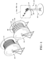
- a device made in accordance with the present invention is generally indicated by the numeral 10, and is depicted at the site where a cable 11 is introduced into an underground conduit.
- Device 10 applies a sleeve 12 to the cable 11 and together they are introduced into a conduit.
- a supply of cable 11 is carried by a conventional reel 13, and a supply of the sleeve 12 is carried by a conventional reel 14.
- Sleeve 12 may be made of any suitable material, preferably a fabric material, which has a coefficient of friction less than that of the cable so that a sleeved cable can be more easily instead into a conduit than a bare cable.
- reel 13 and reel 14 can carry one or more thousand feet of cable 11 and sleeve 12 for introduction into the conduit.
- Device 10 includes a stand 15 that can be positioned on the ground.
- Stand 15 carries a tube 16 which receives a post 17.
- Tube 16 is provided with a plurality of apertures 18, and post 17 is provided with a plurality of apertures 19.
- An aperture 18 can be aligned with an aperture 19 and a pin (not shown) or other device is provided through the apertures. As such, the height of device 10 can be adjusted.
- Sleeve 12 is in the form of a strip of material 25 having opposed compatible attachment members 26, 27 formed at the lateral edges of the strip of material 25 as by stitching.
- the overall width of the sleeve 12 is preferably slightly larger than the circumference of the cable 11 that is selected for insertion. As a result, sleeve 12 surrounds cable 11, but cable 11 may be pulled through sleeve 12 as may be necessary as will hereafter be described.
- Attachment members 26, 27 are preferably, respectively, the hook and loop components of VELCO ® attachment system, but could include other attachment devices such as an adhesive or the like.
- Each former 21, 22, and 23 includes a generally crescent shaped body 30 integrally carried by a hub 31 which provides the means to be connected to body 20.
- a slot is formed in body 30.
- Slot 32 includes an arcuate portion 33 and enlarged portions 34 and 35 at the ends of arcuate portion 33.
- the sleeve 12 is received in slot 32 with the strip of material 25 being received in arcuate portion 33 and the attachment members 26, 27 being received in enlarged slot portions 34 and 35, respectively.
- Device 10 also includes a sleeve attachment portion generally indicated by the numeral 40 and positioned adjacent to third former 23.
- Attachment portion 40 is carried by post 17 and to that end includes a plate 41 which may be welded or otherwise attached to post 17.
- a pivotable plate 42 is carried by plate 41 by means of a threaded pivot pin 43 which extends through a hole 44 in plate 41 and through a hole 45 in plate 42 to be engaged by a wing nut 46.
- Another pin 47 extends through a hole 48 in plate 41 and through an adjustment slot 49 in plate 42 to be engaged by a wing nut 50. As such, by loosening wing nut 50, pin 47 may be moved in slot 49 to a desired position to adjust the angular position of plate 42, and all of the components attached to plate 42, now to be described, relative to post 17.
- Plate 42 is attached to beam 20 by a plurality of bolts 51 as shown in Fig. 3A .
- Plate 42 also carries an attachment unit generally indicated by the numeral 52 and best shown in Figs. 7 and 8 .
- Attachment unit 52 is formed by two plates 53 and 54 joined by a hinge 55.
- Each plate 53, 54 is provided with a semicircular recess 56 which, when plates 53 and 54 are closed against each other, form an aperture 57 approximately the size of the cable 11 with the sleeve 12 on it.
- Each plate 53, 54 is provided with a first channel 58, a second channel 59, and a third deeper channel 60 located between channels 58 and 59.
- a recess 61 is formed.
- recess 61 receives and attaches the attachment members 26 and 27 with the opposed deeper channels 60 forming a space for the stitching that attaches the members 26 and 27 to the strip of material 25.
- Plate 53 is attached to plate 42 by being welded or the like.
- plate 54 carries, as by welding, a flap 62.
- Flap 62 is provided with two pins 63 which are aligned with threaded lugs 64 on plate 42, and flap 62 may be attached to plate 42 to hold plates 53 and 54 together on their hinge 55 by knob screws 65.
- roller assembly 66 The cable 11 and sleeve 12 may be guided into and out of attachment portion 40 by roller assembles generally indicated by the numeral 66.
- Each roller assembly 66 includes brackets 67 having one end attached to beam 20 as by bolts 68. The other end is journaled so as to have a busing or roller 69 carried thereby. As such, as the cable and sleeve combination travel through device 10, rollers 69 can ease and align the entry and exit from attachment portion 40, as may be necessary.
- the operation of device 10 will now be described in detail.
- the device 10, as well as the reel 13 of cable 11 and reel 14 of sleeve 12, are positioned at a cable installation site such as a manhole or the like.
- the height of device 10 and the angular orientation of the attachment unit 52 may be adjusted, as previously described, as may be necessary for ease of entry into the conduit, the access to which has been gained in the manhole.
- the sleeve With the attachment unit 52 open, as shown in Fig. 1A , the sleeve is threaded through the arcuate portions 33 of slots 32 of formers 21, 22 and 23. Because of the decreasing radii of curvature of arcuate positions 33, sleeve begins a sequence of folding around a cable 11, as shown in Fig. 2A , and once the attachment unit 52 is closed, the attachment members, which have been received in portions 34 and 35 of slots 32, engage each other. The cable 11 is also fed into the device 10 onto the recess 36 in each former body 30 and beneath covers 37 as shown in Fig. 3A .
- a pull rope or tape is typically already positioned in the conduit, and it is attached to the exposed end of the cable 11 and sleeve 12 shown in Fig. 3 .
- a pulling device is located at another access point, such as another of a plurality of manholes, downstream of the location of device 10. Once attached, the pulling device is activated to automatically pull cable 11 off of reel 13 and sleeve off of reel 14 and through device 10 which automatically wraps the sleeve 12 around the cable which is then continuously moved through the conduit.
- the attachment unit 52 is opened on hinge 55, caps 37 are taken off the formers 21 and 22, and the sleeved cable may be removed from the device.
- the sleeve can be cut from around the "rear" end of the cable that has been pulled to the next downstream location.
- the device 10 and the sleeve roll are moved to the next downstream location and the exposed end of the cable, as it is shown in Fig. 3A is at the downstream location, and the cable can be slid through the sleeve until enough cable is exposed to be received again in device 10 with a new supply of sleeve.
- the expanse of sleeve between the two manholes stays in place as the new supply of sleeve is applied to the bare cable that is being pulled into the next conduit section. This process is continued, from manhole to manhole, until the desired length of cable has been covered with the sleeve.
Landscapes
- Engineering & Computer Science (AREA)
- Architecture (AREA)
- Civil Engineering (AREA)
- Structural Engineering (AREA)
- Manufacturing & Machinery (AREA)
- Laying Of Electric Cables Or Lines Outside (AREA)
- Details Of Indoor Wiring (AREA)
- Installation Of Indoor Wiring (AREA)
- Manufacturing Of Electric Cables (AREA)
Abstract
Description
- This invention relates to a device which applies a sleeve to a communications cable. More particularly, this invention relates to a device which can be utilized at the site where the cable is introduced into an underground conduit.
- Positioning cables in underground communication conduits which extend for several thousand feet has long been a problem. Such is particularly true when it is desired to position an additional cable or cables into a conduit that already has a cable in it. That cable, particularly because of its plastic jacket, provides a great deal of friction to the new cable as it is being inserted into the conduit. As a result, the new or the existing cable may be damaged due to that friction. Such is particularly true when the cable in the conduit is undulating which causes the cable being introduced to take a sinuous, friction-laden path.
- An extremely successful solution to this problem is a fabric innerduct sold under the trademark MAXCELL® by WESCO Distribution, Inc. of Pittsburgh, Pennsylvania and shown in
U.S. Patent No. 6,262,371 which is incorporated herein by reference for whatever details may be necessary to understand the present invention. This innerduct can be first positioned in a conduit to divide the conduit into longitudinally extending compartments. A cable can be positioned in one of the compartments, and a pull tape or rope can be positioned in another compartment which can later be utilized to pull a second cable into that compartment. Because there is fabric between the cables, the friction is not on the cable jacket but on the fabric which makes installation easier. - While such provides an extremely efficient solution to the problem, its use is a two-step operation. That is, first the innerduct is installed in the conduit and then a cable is inserted into the innerduct. As a result, a system was designed whereby a fabric sleeve, having a coefficient of frictionless than that of a cable, is provided around the sleeve and then, in a one-step process, the cable with the sleeve on it can be inserted into a conduit. Such a system is described, for example, in
U.S. Patent No. 10,937,568 - That patent contemplates that the sleeve could be attached to the cable while the cable is being introduced into an underground conduit. The present invention relates to a device which accomplishes that function.
- It is thus an object of one aspect of the present invention to provide a device which applies a sleeve to a cable.
- It is an object of another aspect of the present invention to provide a device, as above, which applies the sleeve to the cable as the cable is being introduced into a conduit.
- It is an object of an additional aspect of the present invention to provide a device, as above, which receives the cable from a roll of cable, and receives the sleeve from a roll of the sleeve, and automatically aligns the sleeve around the cable and provides a sealing mechanism to lock the sleeve on to the cable.
- It is an object of a further aspect of the invention to provide a method of inserting a sleeved cable into a conduit.
- These and other objects of the present invention, as well as the advantages thereof over existing prior art forms, which will become apparent from the description to follow, are accomplished by the improvements hereinafter described and claimed.
- In general, a sleeve in the form of a strip of material having compatible attachment members along its lateral edges is applied around a cable by an apparatus which includes a post, and a beam carried by the post. A plurality of formers are carried at spaced locations along the beam. The formers receive the cable and the sleeve and fold the sleeve around the cable. An attachment device which is carried by the beam receives the sleeve and the cable from the formers and connects the attachment members so that the sleeve is applied to the cable.
- In accordance with another aspect of the invention, a sleeve of material is applied around a cable by an apparatus which includes a beam. First and second formers are spaced along the beam, each former receiving the cable and the sleeve. The sleeve is received in an arcuate slot provided in each former. The radius of curvature of the slot in the first former is larger than the radius of curvature of the slot in the second former so that the sleeve is being wrapped around the cable as the sleeve and the cable move along the beam.
- In accordance with another aspect of the invention, a sleeve in the form of a strip of material having compatible attachment members along its lateral edges is applied around a cable by an apparatus which includes a beam. A plurality of formers are carried by the beam, the formers receiving the cable and the sleeve and folding the sleeve around the cable. An attachment device receives the cable and the sleeve from the formers and incudes two plates joined by a hinge. When the plates are closed against each other, the attachment members are connected to e,ach other, and when the plates are rotated on the hinge to an open position, the cable having the sleeve applied thereto may be removed from the apparatus.
- The invention also includes a method of creating a cable with a sleeve around it, and installing the sleeved cable into a conduit at a plurality of spaced installation sites. The cable and sleeve are fed into a device which applies the sleeve to the cable. The sleeved cable is introduced into a conduit which is accessed at a first installation site. The sleeved cable is transferred through the conduit to a second installation site. When the sleeved cable reaches the second installation site, the sleeved cable is removed from the device and the sleeve is cut to form a first portion of a sleeved cable between the first and second installation sites. At the second installation site, the cable and a sleeve are fed into a device which applies the sleeve to the cable. The sleeved cable is then transferred form the second installation site through the conduit toward the next installation site to ultimately form a second portion of sleeved conduit between the second and the next installation site.
- A preferred exemplary embodiment of a device for applying a sleeve to a cable according to the concepts of the present invention is shown by way of example in the accompanying drawings without attempting to show all of the various forms and modifications in which the invention might be embodied, the invention being measured by the appended claims and not by the details of the specification.
-
-
Fig. 1 is a perspective view of the device of the present invention shown in the environment of a site where a cable, to be covered with a sleeve, is to be inserted into an underground conduit. -
Fig. 1A is a fragmented, enlarged view of the device encircled inFig. 1 . -
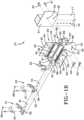
Fig. 1B is similar toFig. 1A but with components of the device being shown in an exploded form. -
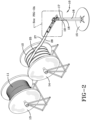
Fig. 2 is a view similar toFig. 1 but showing the sleeve positioned in the device. -
Fig. 2A is a fragmented, enlarged view of the device encircled inFig. 2 . -
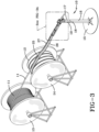
Fig. 3 is a view similar toFig. 2 but showing the cable positioned in the device. -
Fig. 3A is a fragmented, enlarged view of the device encircled inFig. 3 . -
Fig. 4 is an elevational view of the first former which receives the sleeve. -
Fig. 5 is an elevational view of the second former which receives the sleeve. -
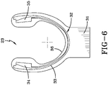
Fig. 6 is an elevational view of the third former which receives the sleeve. -
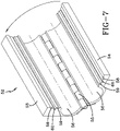
Fig. 7 is a perspective view of a portion of the attachment assembly shown in an open position. -
Fig. 8 is a perspective view with the position of the attachment assembly shown inFig. 7 in a closed position. -
Fig. 9 is an end view of that which is shown inFig. 8 and schematically showing the cable and showing the sleeve positioned thereon. - A device made in accordance with the present invention is generally indicated by the numeral 10, and is depicted at the site where a
cable 11 is introduced into an underground conduit.Device 10 applies asleeve 12 to thecable 11 and together they are introduced into a conduit. A supply ofcable 11 is carried by aconventional reel 13, and a supply of thesleeve 12 is carried by aconventional reel 14.Sleeve 12 may be made of any suitable material, preferably a fabric material, which has a coefficient of friction less than that of the cable so that a sleeved cable can be more easily instead into a conduit than a bare cable. As is known in the art, reel 13 and reel 14 can carry one or more thousand feet ofcable 11 andsleeve 12 for introduction into the conduit. -
Device 10 includes astand 15 that can be positioned on the ground. Stand 15 carries atube 16 which receives apost 17.Tube 16 is provided with a plurality ofapertures 18, and post 17 is provided with a plurality ofapertures 19. Anaperture 18 can be aligned with anaperture 19 and a pin (not shown) or other device is provided through the apertures. As such, the height ofdevice 10 can be adjusted. -
Post 17 carries themain beam 20 of the device such thatbeam 20 extends generally laterally frompost 17.Beam 20 carries a plurality of former assemblies, a first former being generally indicated by the numeral 21 and shown inFig. 4 , a second former being generally indicated by the numeral 22 and shown inFig. 5 , and a third former being generally indicated by the numeral 23 and shown inFig. 6 .Formers beam 20, by being bolted or otherwise attached through selectedholes 24 inbeam 20.Formers 21, 22- and23-fold sleeve 12 aroundcable 11 in a manner to be hereinafter described. -
Sleeve 12 is in the form of a strip ofmaterial 25 having opposedcompatible attachment members material 25 as by stitching. The overall width of thesleeve 12 is preferably slightly larger than the circumference of thecable 11 that is selected for insertion. As a result,sleeve 12 surroundscable 11, butcable 11 may be pulled throughsleeve 12 as may be necessary as will hereafter be described.Attachment members - Each former 21, 22, and 23 includes a generally crescent shaped
body 30 integrally carried by ahub 31 which provides the means to be connected tobody 20. A slot, generally indicated by the numeral 32, is formed inbody 30.Slot 32 includes anarcuate portion 33 andenlarged portions arcuate portion 33. Thesleeve 12 is received inslot 32 with the strip ofmaterial 25 being received inarcuate portion 33 and theattachment members enlarged slot portions - The top center of
body 30 is provided with anarcuate recess 36 which is adapted to receive thecable 11. As shown inFig. 1B , acover 37 may be removably attached tobody 30 as bybolts 38 extending throughcover 37 and into threadedholes 39 inbody 30.Cover 37 serves to confine thecable 11 inrecess 36. Although each former 21, 22 and 23 may be provided with acover 37, such is shown as not being provided for third former 23 as it has been found that acover 37 for former 23 may not be necessary. - Thus
formers arcuate portion 33. As will hereinafter become evident, thearcuate portion 33 of former 21 (Fig. 4 ) has a larger radius of curvature than thearcuate portion 33 of former 22 (Fig. 5 ) which, in turn, has a larger radius of curate than thearcuate portion 33 of former 23 (Fig. 6 ). -
Device 10 also includes a sleeve attachment portion generally indicated by the numeral 40 and positioned adjacent to third former 23.Attachment portion 40 is carried bypost 17 and to that end includes aplate 41 which may be welded or otherwise attached to post 17. Apivotable plate 42 is carried byplate 41 by means of a threadedpivot pin 43 which extends through ahole 44 inplate 41 and through ahole 45 inplate 42 to be engaged by awing nut 46. Anotherpin 47 extends through ahole 48 inplate 41 and through anadjustment slot 49 inplate 42 to be engaged by awing nut 50. As such, by looseningwing nut 50,pin 47 may be moved inslot 49 to a desired position to adjust the angular position ofplate 42, and all of the components attached to plate 42, now to be described, relative to post 17. -
Plate 42 is attached tobeam 20 by a plurality ofbolts 51 as shown inFig. 3A .Plate 42 also carries an attachment unit generally indicated by the numeral 52 and best shown inFigs. 7 and8 .Attachment unit 52 is formed by twoplates hinge 55. Eachplate semicircular recess 56 which, whenplates aperture 57 approximately the size of thecable 11 with thesleeve 12 on it. - Each
plate first channel 58, asecond channel 59, and a thirddeeper channel 60 located betweenchannels plates Fig. 8 , arecess 61 is formed. As will hereinafter become evident,recess 61 receives and attaches theattachment members deeper channels 60 forming a space for the stitching that attaches themembers material 25. -
Plate 53 is attached to plate 42 by being welded or the like. As shown, for example inFig. 1B ,plate 54 carries, as by welding, aflap 62.Flap 62 is provided with twopins 63 which are aligned with threadedlugs 64 onplate 42, andflap 62 may be attached to plate 42 to holdplates hinge 55 by knob screws 65. - The
cable 11 andsleeve 12 may be guided into and out ofattachment portion 40 by roller assembles generally indicated by the numeral 66. Eachroller assembly 66 includesbrackets 67 having one end attached tobeam 20 as bybolts 68. The other end is journaled so as to have a busing orroller 69 carried thereby. As such, as the cable and sleeve combination travel throughdevice 10,rollers 69 can ease and align the entry and exit fromattachment portion 40, as may be necessary. - The operation of
device 10 will now be described in detail. Thedevice 10, as well as thereel 13 ofcable 11 and reel 14 ofsleeve 12, are positioned at a cable installation site such as a manhole or the like. The height ofdevice 10 and the angular orientation of theattachment unit 52 may be adjusted, as previously described, as may be necessary for ease of entry into the conduit, the access to which has been gained in the manhole. - With the
attachment unit 52 open, as shown inFig. 1A , the sleeve is threaded through thearcuate portions 33 ofslots 32 offormers arcuate positions 33, sleeve begins a sequence of folding around acable 11, as shown inFig. 2A , and once theattachment unit 52 is closed, the attachment members, which have been received inportions slots 32, engage each other. Thecable 11 is also fed into thedevice 10 onto therecess 36 in eachformer body 30 and beneath covers 37 as shown inFig. 3A . - A pull rope or tape is typically already positioned in the conduit, and it is attached to the exposed end of the
cable 11 andsleeve 12 shown inFig. 3 . A pulling device is located at another access point, such as another of a plurality of manholes, downstream of the location ofdevice 10. Once attached, the pulling device is activated to automatically pullcable 11 off ofreel 13 and sleeve off ofreel 14 and throughdevice 10 which automatically wraps thesleeve 12 around the cable which is then continuously moved through the conduit. - When the sleeved cable reaches the next downstream location, the
attachment unit 52 is opened onhinge 55, caps 37 are taken off theformers device 10 and the sleeve roll are moved to the next downstream location and the exposed end of the cable, as it is shown inFig. 3A is at the downstream location, and the cable can be slid through the sleeve until enough cable is exposed to be received again indevice 10 with a new supply of sleeve. The expanse of sleeve between the two manholes stays in place as the new supply of sleeve is applied to the bare cable that is being pulled into the next conduit section. This process is continued, from manhole to manhole, until the desired length of cable has been covered with the sleeve. - In view of the foregoing, it should be evident that a device constructed as described accomplishes the objects of the invention as substantially improves the art.
Claims (15)
- An apparatus for applying a sleeve around a cable, the sleeve being in the form of a strip of material having compatible attachment members positioned along its lateral edges, the apparatus comprising a post, a beam carried by said post, a plurality of formers carried at spaced locations along said beam, said formers receiving the cable and the sleeve and folding the sleeve around the cable, and an attachment device carried by said beam, said attachment device receiving the sleeve and the cable from said formers and connecting the attachment members so that the sleeve is applied to the cable.
- The apparatus of claim 1, each said former having an arcuate slot to receive the sleeve, the radius of curvature of said slots varying from former to former so that the sleeve progressively surrounds the cable.
- The apparatus of claim 2, wherein each said arcuate slot has enlarged ends to receive the attachment members.
- The apparatus of claim 2, wherein each said former has an arcuate recess above said slot, said recess being adapted to receive the cable, and, optionally, the apparatus further comprising a cover removably positioned over said recess of said formers to confine the cable in said recess.
- The apparatus of claim 1 further comprising one ofa roller carried by said beam between said formers and said attachment device;a second roller carried by said beam and adapted to receive the cable and sleeve from the attachment device;means to adjust the height of said post; ormeans to rotate said attachment device relative to said post.
- The apparatus of claim 1 wherein said attachment device includes a first plate and a second plate with a hinge between said plates which allows said plates to rotate relative to each other from a closed position with the plates being adjacent to each other to an open position.
- The apparatus of claim 6 further comprising means to attach said plates when in the closed position.
- The apparatus of claim 6, wherein each said plate has a recess such that when in the closed position, the recesses form an aperture for the cable, or wherein each said plate includes at least one channel such that when in the closed position, the channels form a recess for, and attaches, the attachment members.
- An apparatus for applying a sleeve of material around a cable comprising a beam, a first former carried by said beam, a second former carried by said beam and being spaced from said first former, each said former receiving the cable and the sleeve, the sleeve being received in an arcuate slot provided in each said former, the radius of curvature of said slot in said first former being larger than the radius of curvature of said slot in said second former such that the sleeve is being wrapped around the cable as the sleeve and cable move along said beam.
- The apparatus of claim 9 wherein the sleeve is the form of a strip of material having compatible attachment members positioned along its lateral edges, and further comprising an attachment device carried by said beam and receiving the cable and the sleeve from said formers and attaching said attachment members to each other so that the sleeve is applied to the cable, and, optionally, wherein said slots of said formers have enlarged ends to receive the attachment members, or wherein said attachment device is moveable from an open position to a closed position so that the cable with the sleeve on it can be removed from the apparatus.
- The apparatus of claim 9 wherein each said former include an arcuate recess above said slots, said recess being adapted to receive the cable, and, optionally, wherein each said former is provided with a cover over said recess, said covers confirming the cable in said formers but being removeable so that the cable can be removed from the apparatus.
- An apparatus for applying a sleeve around a cable, the sleeve being in the form of a strip of material having compatible attachment members positioned along its lateral edges, the apparatus comprising a beam, a plurality of formers carried by said beam, said formers receiving the cable and the sleeve and folding the sleeve around the cable, and an attachment device receiving the cable and the sleeve from said formers and having two plates joined by a hinge, such that when said plates are closed against each other, the attachment members are connected to each other, and when said plates are rotated on said hinge to an open position, the cable having the sleeve applied thereto may be removed from the apparatus.
- The apparatus of claim 12 further comprising means to attach said plates together when in the closed position or heads to pivot said attachment device.
- The apparatus of claim 12, wherein each plate has a recess such that when in the closed position, the recesses form an aperture for the cable, or wherein each said plate includes at least one channel such that when in the closed position, the channels form a recess for, and attaches, the attachment member.
- A method of creating a cable with a sleeve around it and installing the sleeved cable into a conduit at a plurality of spaced installation sites comprising the steps of feeding the cable and the sleeve into a device which applies the sleeve to the cable; introducing the sleeved cable into a conduit which is accessed at a first installation site; transferring the sleeved cable through the conduit toward a second installation site; when the sleeved cable reaches the second installation site, removing the sleeved cable from the device and cutting the sleeve forming a first portion of sleeved conduit between the first and second installation sites; at the second installation site, feeding the cable; and a sleeve into a device which applies the sleeve to the cable; and transferring the sleeved cable from the second installation site through the conduit toward the next installation site to ultimately form a second portion of sleeved conduit between the second and the next installation site.
Applications Claiming Priority (1)
| Application Number | Priority Date | Filing Date | Title |
|---|---|---|---|
| US17/475,693 US12009118B2 (en) | 2021-09-15 | 2021-09-15 | Apparatus for applying a sleeve to a cable and method of insertion into a conduit |
Publications (2)
| Publication Number | Publication Date |
|---|---|
| EP4152535A1 true EP4152535A1 (en) | 2023-03-22 |
| EP4152535B1 EP4152535B1 (en) | 2025-08-27 |
Family
ID=83283383
Family Applications (1)
| Application Number | Title | Priority Date | Filing Date |
|---|---|---|---|
| EP22194727.8A Active EP4152535B1 (en) | 2021-09-15 | 2022-09-08 | Apparatus for applying a sleeve to a cable and method of insertion into a conduit |
Country Status (7)
| Country | Link |
|---|---|
| US (3) | US12009118B2 (en) |
| EP (1) | EP4152535B1 (en) |
| CA (1) | CA3172943A1 (en) |
| DK (1) | DK4152535T3 (en) |
| ES (1) | ES3044219T3 (en) |
| FI (1) | FI4152535T3 (en) |
| MX (1) | MX2022011357A (en) |
Families Citing this family (1)
| Publication number | Priority date | Publication date | Assignee | Title |
|---|---|---|---|---|
| US20230305258A1 (en) * | 2022-03-25 | 2023-09-28 | Wesco Distribution, Inc. | Innerduct for fiberoptic cables and its method of manufacture |
Citations (6)
| Publication number | Priority date | Publication date | Assignee | Title |
|---|---|---|---|---|
| GB1534279A (en) * | 1975-02-13 | 1978-11-29 | Bicc Ltd | Electric cables |
| US4270963A (en) * | 1979-09-17 | 1981-06-02 | Northern Telecom Limited | Wrapping articles of indefinite length |
| US6262371B1 (en) | 1999-06-23 | 2001-07-17 | Marc Talon, Inc. | Method and apparatus for dividing a conduit into compartments |
| DE112013002894T5 (en) * | 2012-06-11 | 2015-03-05 | Yazaki Corporation | Exterior element attachment device and exterior element attachment method |
| US20200235554A1 (en) * | 2008-06-23 | 2020-07-23 | Wesco Distribution, Inc. | Communications cable with fabric sleeve |
| US10937568B2 (en) | 2019-01-30 | 2021-03-02 | Wesco Distribution Inc. | Attachment of a fabric sleeve to a communications cable |
Family Cites Families (8)
| Publication number | Priority date | Publication date | Assignee | Title |
|---|---|---|---|---|
| US1582026A (en) * | 1923-05-02 | 1926-04-27 | Western Electric Co | Method of and apparatus for producing plastic articles |
| US2462303A (en) * | 1946-11-23 | 1949-02-22 | Western Electric Co | Material serving apparatus |
| US3753279A (en) * | 1971-04-13 | 1973-08-21 | Thomas & Betts Corp | Terminal forming & terminating apparatus |
| US4415223A (en) * | 1981-06-03 | 1983-11-15 | Amp Incorporated | Interlocking crimp sleeve and method of securing to connector |
| JP4627061B2 (en) * | 2006-11-14 | 2011-02-09 | 株式会社オートネットワーク技術研究所 | Shielded wire processed terminal and manufacturing method thereof |
| US9793029B2 (en) * | 2015-01-21 | 2017-10-17 | Itt Manufacturing Enterprises Llc | Flexible, pressure-balanced cable assembly |
| US20190381721A1 (en) * | 2018-06-18 | 2019-12-19 | Federal-Mogul Powertrain Llc | Tool for fixing a textile sleeve about an elongate member and method of fixing a textile sleeve about an elongate member |
| JP7109351B2 (en) * | 2018-12-07 | 2022-07-29 | 日本航空電子工業株式会社 | connector terminal |
-
2021
- 2021-09-15 US US17/475,693 patent/US12009118B2/en active Active
-
2022
- 2022-09-08 EP EP22194727.8A patent/EP4152535B1/en active Active
- 2022-09-08 ES ES22194727T patent/ES3044219T3/en active Active
- 2022-09-08 DK DK22194727.8T patent/DK4152535T3/en active
- 2022-09-08 FI FIEP22194727.8T patent/FI4152535T3/en active
- 2022-09-12 MX MX2022011357A patent/MX2022011357A/en unknown
- 2022-09-13 CA CA3172943A patent/CA3172943A1/en active Pending
-
2024
- 2024-03-14 US US18/604,982 patent/US12518896B2/en active Active
- 2024-05-15 US US18/664,652 patent/US20240296978A1/en active Pending
Patent Citations (6)
| Publication number | Priority date | Publication date | Assignee | Title |
|---|---|---|---|---|
| GB1534279A (en) * | 1975-02-13 | 1978-11-29 | Bicc Ltd | Electric cables |
| US4270963A (en) * | 1979-09-17 | 1981-06-02 | Northern Telecom Limited | Wrapping articles of indefinite length |
| US6262371B1 (en) | 1999-06-23 | 2001-07-17 | Marc Talon, Inc. | Method and apparatus for dividing a conduit into compartments |
| US20200235554A1 (en) * | 2008-06-23 | 2020-07-23 | Wesco Distribution, Inc. | Communications cable with fabric sleeve |
| DE112013002894T5 (en) * | 2012-06-11 | 2015-03-05 | Yazaki Corporation | Exterior element attachment device and exterior element attachment method |
| US10937568B2 (en) | 2019-01-30 | 2021-03-02 | Wesco Distribution Inc. | Attachment of a fabric sleeve to a communications cable |
Also Published As
| Publication number | Publication date |
|---|---|
| US20240296978A1 (en) | 2024-09-05 |
| US12518896B2 (en) | 2026-01-06 |
| FI4152535T3 (en) | 2025-10-07 |
| EP4152535B1 (en) | 2025-08-27 |
| ES3044219T3 (en) | 2025-11-26 |
| US12009118B2 (en) | 2024-06-11 |
| MX2022011357A (en) | 2023-03-16 |
| US20240221980A1 (en) | 2024-07-04 |
| DK4152535T3 (en) | 2025-10-13 |
| US20230077480A1 (en) | 2023-03-16 |
| CA3172943A1 (en) | 2023-03-15 |
Similar Documents
| Publication | Publication Date | Title |
|---|---|---|
| US20240296978A1 (en) | Apparatus for applying a sleeve to a cable and method of insertion into a conduit | |
| US6419424B1 (en) | Coil pipe trailer | |
| US4896997A (en) | Cable sheathing and burying method | |
| EP0038789B1 (en) | Method and arrangement on extracting, reeling up, pulling in, ect., of a heavy cable or similar | |
| US7717646B2 (en) | Method and apparatus for deploying a tubular | |
| EP2294665B1 (en) | Communications cable with fabric sleeve | |
| KR20090023165A (en) | A device that introduces two items simultaneously into one pipeline | |
| US20020158239A1 (en) | Optical cable installation with mini-bend reduction | |
| US20260043511A1 (en) | CIPP Liner Feed Roller | |
| US11084686B2 (en) | Cable storage devices and methods of use thereof | |
| US20090084605A1 (en) | Indexing for coiled tubing drilling rig | |
| CA2962288A1 (en) | Cipp liner reel system | |
| US3944161A (en) | Tape laying device and method | |
| US3971544A (en) | Apparatus for guiding a rod into a conduit | |
| JP2002504795A (en) | Clamp insertion device for elongated objects | |
| US5911381A (en) | Stocking device for coilable elements and method of use | |
| EP0858389A1 (en) | Method and apparatus for lining a conduit | |
| WO1999040357A1 (en) | Cable guide for pipes | |
| US4529171A (en) | Cable-guiding apparatus | |
| KR20180134069A (en) | Pulling installation apparatus for plastic corrugated pipe | |
| WO2019236531A1 (en) | Cable with a fabric sleeve and its method of manufacture | |
| DE19524597A1 (en) | Spooling device for cables or optical fibres - uses tripod with L=bend cable guide and compressed air-driven push- and-pull device for cable and guide tube beneath it | |
| CN218053998U (en) | Winding device | |
| JPS6250804B2 (en) | ||
| JP3346844B2 (en) | Electa for shield machine |
Legal Events
| Date | Code | Title | Description |
|---|---|---|---|
| PUAI | Public reference made under article 153(3) epc to a published international application that has entered the european phase |
Free format text: ORIGINAL CODE: 0009012 |
|
| STAA | Information on the status of an ep patent application or granted ep patent |
Free format text: STATUS: THE APPLICATION HAS BEEN PUBLISHED |
|
| AK | Designated contracting states |
Kind code of ref document: A1 Designated state(s): AL AT BE BG CH CY CZ DE DK EE ES FI FR GB GR HR HU IE IS IT LI LT LU LV MC MK MT NL NO PL PT RO RS SE SI SK SM TR |
|
| STAA | Information on the status of an ep patent application or granted ep patent |
Free format text: STATUS: REQUEST FOR EXAMINATION WAS MADE |
|
| 17P | Request for examination filed |
Effective date: 20230918 |
|
| RBV | Designated contracting states (corrected) |
Designated state(s): AL AT BE BG CH CY CZ DE DK EE ES FI FR GB GR HR HU IE IS IT LI LT LU LV MC MK MT NL NO PL PT RO RS SE SI SK SM TR |
|
| GRAP | Despatch of communication of intention to grant a patent |
Free format text: ORIGINAL CODE: EPIDOSNIGR1 |
|
| STAA | Information on the status of an ep patent application or granted ep patent |
Free format text: STATUS: GRANT OF PATENT IS INTENDED |
|
| RIC1 | Information provided on ipc code assigned before grant |
Ipc: H02G 9/06 20060101ALN20250228BHEP Ipc: H02G 1/08 20060101AFI20250228BHEP |
|
| RIC1 | Information provided on ipc code assigned before grant |
Ipc: H02G 9/06 20060101ALN20250310BHEP Ipc: H02G 1/08 20060101AFI20250310BHEP |
|
| INTG | Intention to grant announced |
Effective date: 20250321 |
|
| GRAS | Grant fee paid |
Free format text: ORIGINAL CODE: EPIDOSNIGR3 |
|
| GRAA | (expected) grant |
Free format text: ORIGINAL CODE: 0009210 |
|
| STAA | Information on the status of an ep patent application or granted ep patent |
Free format text: STATUS: THE PATENT HAS BEEN GRANTED |
|
| AK | Designated contracting states |
Kind code of ref document: B1 Designated state(s): AL AT BE BG CH CY CZ DE DK EE ES FI FR GB GR HR HU IE IS IT LI LT LU LV MC MK MT NL NO PL PT RO RS SE SI SK SM TR |
|
| REG | Reference to a national code |
Ref country code: CH Ref legal event code: EP |
|
| REG | Reference to a national code |
Ref country code: DE Ref legal event code: R096 Ref document number: 602022020126 Country of ref document: DE |
|
| REG | Reference to a national code |
Ref country code: CH Ref legal event code: U11 Free format text: ST27 STATUS EVENT CODE: U-0-0-U10-U11 (AS PROVIDED BY THE NATIONAL OFFICE) Effective date: 20251001 |
|
| REG | Reference to a national code |
Ref country code: FI Ref legal event code: FGE |
|
| REG | Reference to a national code |
Ref country code: IE Ref legal event code: FG4D |
|
| PGFP | Annual fee paid to national office [announced via postgrant information from national office to epo] |
Ref country code: FI Payment date: 20250912 Year of fee payment: 4 |
|
| PGFP | Annual fee paid to national office [announced via postgrant information from national office to epo] |
Ref country code: DE Payment date: 20250819 Year of fee payment: 4 |
|
| REG | Reference to a national code |
Ref country code: DK Ref legal event code: T3 Effective date: 20251006 Ref country code: CH Ref legal event code: R17 Free format text: ST27 STATUS EVENT CODE: U-0-0-R10-R17 (AS PROVIDED BY THE NATIONAL OFFICE) Effective date: 20251013 |
|
| REG | Reference to a national code |
Ref country code: SE Ref legal event code: TRGR |
|
| PGFP | Annual fee paid to national office [announced via postgrant information from national office to epo] |
Ref country code: NL Payment date: 20250903 Year of fee payment: 4 |
|
| PGFP | Annual fee paid to national office [announced via postgrant information from national office to epo] |
Ref country code: FR Payment date: 20250821 Year of fee payment: 4 Ref country code: AT Payment date: 20251020 Year of fee payment: 4 |
|
| PGFP | Annual fee paid to national office [announced via postgrant information from national office to epo] |
Ref country code: SE Payment date: 20250827 Year of fee payment: 4 |
|
| PGFP | Annual fee paid to national office [announced via postgrant information from national office to epo] |
Ref country code: IE Payment date: 20250827 Year of fee payment: 4 |
|
| REG | Reference to a national code |
Ref country code: NL Ref legal event code: FP |
|
| REG | Reference to a national code |
Ref country code: ES Ref legal event code: FG2A Ref document number: 3044219 Country of ref document: ES Kind code of ref document: T3 Effective date: 20251126 |
|
| PG25 | Lapsed in a contracting state [announced via postgrant information from national office to epo] |
Ref country code: IS Free format text: LAPSE BECAUSE OF FAILURE TO SUBMIT A TRANSLATION OF THE DESCRIPTION OR TO PAY THE FEE WITHIN THE PRESCRIBED TIME-LIMIT Effective date: 20251227 |
|
| PGFP | Annual fee paid to national office [announced via postgrant information from national office to epo] |
Ref country code: NO Payment date: 20250909 Year of fee payment: 4 |
|
| REG | Reference to a national code |
Ref country code: LT Ref legal event code: MG9D |
|
| PG25 | Lapsed in a contracting state [announced via postgrant information from national office to epo] |
Ref country code: PT Free format text: LAPSE BECAUSE OF FAILURE TO SUBMIT A TRANSLATION OF THE DESCRIPTION OR TO PAY THE FEE WITHIN THE PRESCRIBED TIME-LIMIT Effective date: 20251229 |
|
| PGFP | Annual fee paid to national office [announced via postgrant information from national office to epo] |
Ref country code: IT Payment date: 20250930 Year of fee payment: 4 Ref country code: DK Payment date: 20251113 Year of fee payment: 4 |
|
| PG25 | Lapsed in a contracting state [announced via postgrant information from national office to epo] |
Ref country code: HR Free format text: LAPSE BECAUSE OF FAILURE TO SUBMIT A TRANSLATION OF THE DESCRIPTION OR TO PAY THE FEE WITHIN THE PRESCRIBED TIME-LIMIT Effective date: 20250827 |
|
| PG25 | Lapsed in a contracting state [announced via postgrant information from national office to epo] |
Ref country code: GR Free format text: LAPSE BECAUSE OF FAILURE TO SUBMIT A TRANSLATION OF THE DESCRIPTION OR TO PAY THE FEE WITHIN THE PRESCRIBED TIME-LIMIT Effective date: 20251128 |
|
| PGFP | Annual fee paid to national office [announced via postgrant information from national office to epo] |
Ref country code: CH Payment date: 20251001 Year of fee payment: 4 |
|
| PG25 | Lapsed in a contracting state [announced via postgrant information from national office to epo] |
Ref country code: LV Free format text: LAPSE BECAUSE OF FAILURE TO SUBMIT A TRANSLATION OF THE DESCRIPTION OR TO PAY THE FEE WITHIN THE PRESCRIBED TIME-LIMIT Effective date: 20250827 |
|
| PG25 | Lapsed in a contracting state [announced via postgrant information from national office to epo] |
Ref country code: PL Free format text: LAPSE BECAUSE OF FAILURE TO SUBMIT A TRANSLATION OF THE DESCRIPTION OR TO PAY THE FEE WITHIN THE PRESCRIBED TIME-LIMIT Effective date: 20250827 Ref country code: BG Free format text: LAPSE BECAUSE OF FAILURE TO SUBMIT A TRANSLATION OF THE DESCRIPTION OR TO PAY THE FEE WITHIN THE PRESCRIBED TIME-LIMIT Effective date: 20250827 |
|
| PG25 | Lapsed in a contracting state [announced via postgrant information from national office to epo] |
Ref country code: RS Free format text: LAPSE BECAUSE OF FAILURE TO SUBMIT A TRANSLATION OF THE DESCRIPTION OR TO PAY THE FEE WITHIN THE PRESCRIBED TIME-LIMIT Effective date: 20251127 |
|
| PGFP | Annual fee paid to national office [announced via postgrant information from national office to epo] |
Ref country code: ES Payment date: 20251016 Year of fee payment: 4 |
|
| PG25 | Lapsed in a contracting state [announced via postgrant information from national office to epo] |
Ref country code: RO Free format text: LAPSE BECAUSE OF FAILURE TO SUBMIT A TRANSLATION OF THE DESCRIPTION OR TO PAY THE FEE WITHIN THE PRESCRIBED TIME-LIMIT Effective date: 20250827 |
|
| PG25 | Lapsed in a contracting state [announced via postgrant information from national office to epo] |
Ref country code: SM Free format text: LAPSE BECAUSE OF FAILURE TO SUBMIT A TRANSLATION OF THE DESCRIPTION OR TO PAY THE FEE WITHIN THE PRESCRIBED TIME-LIMIT Effective date: 20250827 |
|
| PG25 | Lapsed in a contracting state [announced via postgrant information from national office to epo] |
Ref country code: CZ Free format text: LAPSE BECAUSE OF FAILURE TO SUBMIT A TRANSLATION OF THE DESCRIPTION OR TO PAY THE FEE WITHIN THE PRESCRIBED TIME-LIMIT Effective date: 20250827 |
|
| PG25 | Lapsed in a contracting state [announced via postgrant information from national office to epo] |
Ref country code: EE Free format text: LAPSE BECAUSE OF FAILURE TO SUBMIT A TRANSLATION OF THE DESCRIPTION OR TO PAY THE FEE WITHIN THE PRESCRIBED TIME-LIMIT Effective date: 20250827 Ref country code: SK Free format text: LAPSE BECAUSE OF FAILURE TO SUBMIT A TRANSLATION OF THE DESCRIPTION OR TO PAY THE FEE WITHIN THE PRESCRIBED TIME-LIMIT Effective date: 20250827 |
|
| PG25 | Lapsed in a contracting state [announced via postgrant information from national office to epo] |
Ref country code: LU Free format text: LAPSE BECAUSE OF NON-PAYMENT OF DUE FEES Effective date: 20250908 |
|
| REG | Reference to a national code |
Ref country code: BE Ref legal event code: MM Effective date: 20250930 Ref country code: DE Ref legal event code: R097 Ref document number: 602022020126 Country of ref document: DE |
|
| PG25 | Lapsed in a contracting state [announced via postgrant information from national office to epo] |
Ref country code: LT Free format text: LAPSE BECAUSE OF FAILURE TO SUBMIT A TRANSLATION OF THE DESCRIPTION OR TO PAY THE FEE WITHIN THE PRESCRIBED TIME-LIMIT Effective date: 20250827 Ref country code: MC Free format text: LAPSE BECAUSE OF FAILURE TO SUBMIT A TRANSLATION OF THE DESCRIPTION OR TO PAY THE FEE WITHIN THE PRESCRIBED TIME-LIMIT Effective date: 20250827 |
|
| PLBE | No opposition filed within time limit |
Free format text: ORIGINAL CODE: 0009261 |
|
| STAA | Information on the status of an ep patent application or granted ep patent |
Free format text: STATUS: NO OPPOSITION FILED WITHIN TIME LIMIT |
|
| REG | Reference to a national code |
Ref country code: CH Ref legal event code: L10 Free format text: ST27 STATUS EVENT CODE: U-0-0-L10-L00 (AS PROVIDED BY THE NATIONAL OFFICE) Effective date: 20260708 |
|
| PG25 | Lapsed in a contracting state [announced via postgrant information from national office to epo] |
Ref country code: BE Free format text: LAPSE BECAUSE OF NON-PAYMENT OF DUE FEES Effective date: 20250930 |
|
| 26N | No opposition filed |
Effective date: 20260528 |