EP4152493A1 - Cylindrical battery - Google Patents
Cylindrical battery Download PDFInfo
- Publication number
- EP4152493A1 EP4152493A1 EP22804067.1A EP22804067A EP4152493A1 EP 4152493 A1 EP4152493 A1 EP 4152493A1 EP 22804067 A EP22804067 A EP 22804067A EP 4152493 A1 EP4152493 A1 EP 4152493A1
- Authority
- EP
- European Patent Office
- Prior art keywords
- case
- sealing member
- insulation sealing
- cylinder
- groove
- Prior art date
- Legal status (The legal status is an assumption and is not a legal conclusion. Google has not performed a legal analysis and makes no representation as to the accuracy of the status listed.)
- Pending
Links
Images


Classifications
-
- H—ELECTRICITY
- H01—ELECTRIC ELEMENTS
- H01M—PROCESSES OR MEANS, e.g. BATTERIES, FOR THE DIRECT CONVERSION OF CHEMICAL ENERGY INTO ELECTRICAL ENERGY
- H01M50/00—Constructional details or processes of manufacture of the non-active parts of electrochemical cells other than fuel cells, e.g. hybrid cells
- H01M50/10—Primary casings; Jackets or wrappings
- H01M50/183—Sealing members
- H01M50/184—Sealing members characterised by their shape or structure
-
- H—ELECTRICITY
- H01—ELECTRIC ELEMENTS
- H01M—PROCESSES OR MEANS, e.g. BATTERIES, FOR THE DIRECT CONVERSION OF CHEMICAL ENERGY INTO ELECTRICAL ENERGY
- H01M10/00—Secondary cells; Manufacture thereof
- H01M10/04—Construction or manufacture in general
- H01M10/0422—Cells or battery with cylindrical casing
-
- H—ELECTRICITY
- H01—ELECTRIC ELEMENTS
- H01M—PROCESSES OR MEANS, e.g. BATTERIES, FOR THE DIRECT CONVERSION OF CHEMICAL ENERGY INTO ELECTRICAL ENERGY
- H01M50/00—Constructional details or processes of manufacture of the non-active parts of electrochemical cells other than fuel cells, e.g. hybrid cells
- H01M50/10—Primary casings; Jackets or wrappings
- H01M50/102—Primary casings; Jackets or wrappings characterised by their shape or physical structure
- H01M50/107—Primary casings; Jackets or wrappings characterised by their shape or physical structure having curved cross-section, e.g. round or elliptic
-
- H—ELECTRICITY
- H01—ELECTRIC ELEMENTS
- H01M—PROCESSES OR MEANS, e.g. BATTERIES, FOR THE DIRECT CONVERSION OF CHEMICAL ENERGY INTO ELECTRICAL ENERGY
- H01M50/00—Constructional details or processes of manufacture of the non-active parts of electrochemical cells other than fuel cells, e.g. hybrid cells
- H01M50/10—Primary casings; Jackets or wrappings
- H01M50/147—Lids or covers
- H01M50/148—Lids or covers characterised by their shape
- H01M50/152—Lids or covers characterised by their shape for cells having curved cross-section, e.g. round or elliptic
-
- H—ELECTRICITY
- H01—ELECTRIC ELEMENTS
- H01M—PROCESSES OR MEANS, e.g. BATTERIES, FOR THE DIRECT CONVERSION OF CHEMICAL ENERGY INTO ELECTRICAL ENERGY
- H01M50/00—Constructional details or processes of manufacture of the non-active parts of electrochemical cells other than fuel cells, e.g. hybrid cells
- H01M50/10—Primary casings; Jackets or wrappings
- H01M50/147—Lids or covers
- H01M50/148—Lids or covers characterised by their shape
- H01M50/154—Lid or cover comprising an axial bore for receiving a central current collector
-
- H—ELECTRICITY
- H01—ELECTRIC ELEMENTS
- H01M—PROCESSES OR MEANS, e.g. BATTERIES, FOR THE DIRECT CONVERSION OF CHEMICAL ENERGY INTO ELECTRICAL ENERGY
- H01M50/00—Constructional details or processes of manufacture of the non-active parts of electrochemical cells other than fuel cells, e.g. hybrid cells
- H01M50/10—Primary casings; Jackets or wrappings
- H01M50/147—Lids or covers
- H01M50/166—Lids or covers characterised by the methods of assembling casings with lids
- H01M50/167—Lids or covers characterised by the methods of assembling casings with lids by crimping
-
- H—ELECTRICITY
- H01—ELECTRIC ELEMENTS
- H01M—PROCESSES OR MEANS, e.g. BATTERIES, FOR THE DIRECT CONVERSION OF CHEMICAL ENERGY INTO ELECTRICAL ENERGY
- H01M50/00—Constructional details or processes of manufacture of the non-active parts of electrochemical cells other than fuel cells, e.g. hybrid cells
- H01M50/10—Primary casings; Jackets or wrappings
- H01M50/147—Lids or covers
- H01M50/166—Lids or covers characterised by the methods of assembling casings with lids
- H01M50/171—Lids or covers characterised by the methods of assembling casings with lids using adhesives or sealing agents
-
- H—ELECTRICITY
- H01—ELECTRIC ELEMENTS
- H01M—PROCESSES OR MEANS, e.g. BATTERIES, FOR THE DIRECT CONVERSION OF CHEMICAL ENERGY INTO ELECTRICAL ENERGY
- H01M50/00—Constructional details or processes of manufacture of the non-active parts of electrochemical cells other than fuel cells, e.g. hybrid cells
- H01M50/10—Primary casings; Jackets or wrappings
- H01M50/172—Arrangements of electric connectors penetrating the casing
- H01M50/174—Arrangements of electric connectors penetrating the casing adapted for the shape of the cells
- H01M50/179—Arrangements of electric connectors penetrating the casing adapted for the shape of the cells for cells having curved cross-section, e.g. round or elliptic
-
- H—ELECTRICITY
- H01—ELECTRIC ELEMENTS
- H01M—PROCESSES OR MEANS, e.g. BATTERIES, FOR THE DIRECT CONVERSION OF CHEMICAL ENERGY INTO ELECTRICAL ENERGY
- H01M50/00—Constructional details or processes of manufacture of the non-active parts of electrochemical cells other than fuel cells, e.g. hybrid cells
- H01M50/10—Primary casings; Jackets or wrappings
- H01M50/183—Sealing members
- H01M50/186—Sealing members characterised by the disposition of the sealing members
- H01M50/188—Sealing members characterised by the disposition of the sealing members the sealing members being arranged between the lid and terminal
-
- H—ELECTRICITY
- H01—ELECTRIC ELEMENTS
- H01M—PROCESSES OR MEANS, e.g. BATTERIES, FOR THE DIRECT CONVERSION OF CHEMICAL ENERGY INTO ELECTRICAL ENERGY
- H01M50/00—Constructional details or processes of manufacture of the non-active parts of electrochemical cells other than fuel cells, e.g. hybrid cells
- H01M50/10—Primary casings; Jackets or wrappings
- H01M50/183—Sealing members
- H01M50/19—Sealing members characterised by the material
- H01M50/193—Organic material
-
- H—ELECTRICITY
- H01—ELECTRIC ELEMENTS
- H01M—PROCESSES OR MEANS, e.g. BATTERIES, FOR THE DIRECT CONVERSION OF CHEMICAL ENERGY INTO ELECTRICAL ENERGY
- H01M50/00—Constructional details or processes of manufacture of the non-active parts of electrochemical cells other than fuel cells, e.g. hybrid cells
- H01M50/10—Primary casings; Jackets or wrappings
- H01M50/183—Sealing members
- H01M50/19—Sealing members characterised by the material
- H01M50/198—Sealing members characterised by the material characterised by physical properties, e.g. adhesiveness or hardness
-
- H—ELECTRICITY
- H01—ELECTRIC ELEMENTS
- H01M—PROCESSES OR MEANS, e.g. BATTERIES, FOR THE DIRECT CONVERSION OF CHEMICAL ENERGY INTO ELECTRICAL ENERGY
- H01M50/00—Constructional details or processes of manufacture of the non-active parts of electrochemical cells other than fuel cells, e.g. hybrid cells
- H01M50/50—Current conducting connections for cells or batteries
- H01M50/543—Terminals
- H01M50/547—Terminals characterised by the disposition of the terminals on the cells
- H01M50/548—Terminals characterised by the disposition of the terminals on the cells on opposite sides of the cell
-
- H—ELECTRICITY
- H01—ELECTRIC ELEMENTS
- H01M—PROCESSES OR MEANS, e.g. BATTERIES, FOR THE DIRECT CONVERSION OF CHEMICAL ENERGY INTO ELECTRICAL ENERGY
- H01M50/00—Constructional details or processes of manufacture of the non-active parts of electrochemical cells other than fuel cells, e.g. hybrid cells
- H01M50/50—Current conducting connections for cells or batteries
- H01M50/543—Terminals
- H01M50/552—Terminals characterised by their shape
- H01M50/559—Terminals adapted for cells having curved cross-section, e.g. round, elliptic or button cells
-
- H—ELECTRICITY
- H01—ELECTRIC ELEMENTS
- H01M—PROCESSES OR MEANS, e.g. BATTERIES, FOR THE DIRECT CONVERSION OF CHEMICAL ENERGY INTO ELECTRICAL ENERGY
- H01M50/00—Constructional details or processes of manufacture of the non-active parts of electrochemical cells other than fuel cells, e.g. hybrid cells
- H01M50/50—Current conducting connections for cells or batteries
- H01M50/572—Means for preventing undesired use or discharge
- H01M50/584—Means for preventing undesired use or discharge for preventing incorrect connections inside or outside the batteries
- H01M50/586—Means for preventing undesired use or discharge for preventing incorrect connections inside or outside the batteries inside the batteries, e.g. incorrect connections of electrodes
-
- H—ELECTRICITY
- H01—ELECTRIC ELEMENTS
- H01M—PROCESSES OR MEANS, e.g. BATTERIES, FOR THE DIRECT CONVERSION OF CHEMICAL ENERGY INTO ELECTRICAL ENERGY
- H01M50/00—Constructional details or processes of manufacture of the non-active parts of electrochemical cells other than fuel cells, e.g. hybrid cells
- H01M50/50—Current conducting connections for cells or batteries
- H01M50/572—Means for preventing undesired use or discharge
- H01M50/584—Means for preventing undesired use or discharge for preventing incorrect connections inside or outside the batteries
- H01M50/588—Means for preventing undesired use or discharge for preventing incorrect connections inside or outside the batteries outside the batteries, e.g. incorrect connections of terminals or busbars
-
- H—ELECTRICITY
- H01—ELECTRIC ELEMENTS
- H01M—PROCESSES OR MEANS, e.g. BATTERIES, FOR THE DIRECT CONVERSION OF CHEMICAL ENERGY INTO ELECTRICAL ENERGY
- H01M50/00—Constructional details or processes of manufacture of the non-active parts of electrochemical cells other than fuel cells, e.g. hybrid cells
- H01M50/50—Current conducting connections for cells or batteries
- H01M50/572—Means for preventing undesired use or discharge
- H01M50/584—Means for preventing undesired use or discharge for preventing incorrect connections inside or outside the batteries
- H01M50/59—Means for preventing undesired use or discharge for preventing incorrect connections inside or outside the batteries characterised by the protection means
-
- Y—GENERAL TAGGING OF NEW TECHNOLOGICAL DEVELOPMENTS; GENERAL TAGGING OF CROSS-SECTIONAL TECHNOLOGIES SPANNING OVER SEVERAL SECTIONS OF THE IPC; TECHNICAL SUBJECTS COVERED BY FORMER USPC CROSS-REFERENCE ART COLLECTIONS [XRACs] AND DIGESTS
- Y02—TECHNOLOGIES OR APPLICATIONS FOR MITIGATION OR ADAPTATION AGAINST CLIMATE CHANGE
- Y02E—REDUCTION OF GREENHOUSE GAS [GHG] EMISSIONS, RELATED TO ENERGY GENERATION, TRANSMISSION OR DISTRIBUTION
- Y02E60/00—Enabling technologies; Technologies with a potential or indirect contribution to GHG emissions mitigation
- Y02E60/10—Energy storage using batteries
Definitions
- the present application relates to the field of batteries, for example, to a cylindrical battery.
- the cylindrical full-tab battery differs from the cylindrical lithium-ion battery in the related art in that a groove opening of the case of the cylindrical lithium-ion battery in the related art is connected to a cap, and the cap serves as a positive connection terminal; however, a groove opening of the case of the cylindrical full-tab battery is connected to a negative cap, and an end face, remote from the groove opening, of the case is riveted to a positive pole, and the positive pole serves as a positive connection terminal.
- the present application provides a cylindrical battery, which can prevent rotation of a positive pole by the cooperation between a case, the positive pole and an insulation sealing member.
- a cylindrical battery which includes a case, a positive pole and an insulation sealing member.
- the case is a cylindrical groove structure.
- the positive pole is riveted to the case, and the insulation sealing member is arranged between the positive pole and the case.
- the insulation sealing member includes an upper insulation sealing member and a lower insulation sealing member, the upper insulation sealing member is arranged outside the case and is engaged with and connected to the case, and the lower insulation sealing member is arranged inside the case.
- At least one of the upper insulation sealing member and the lower insulation sealing member is provided with an annular protrusion block, the annular protrusion block fits closely against an outer sidewall of a portion, passing through the case, of the positive pole, and the outer sidewall of the portion, passing through the case, of the positive pole presses the annular protrusion block towards an inner sidewall of a portion, being passed through, of the case.
- orientation or position relationship indicated by terms such as “center”, “longitudinal”, “transverse”, “length”, “width”, “thickness”, “over”, “below”, “front”, “back”, “left”, “right”, “vertical”, “horizontal”, “top”, “bottom”, “inside”, “outside”, “clockwise” or “counterclockwise” is based on the orientation or position relationship shown in the drawings, which is only for the convenience of describing the present application and simplifying the description, rather than indicating or implying that the device or element referred to must have a specific orientation, be configured and operated in a specific orientation, so it cannot be understood as a limitation to the present application.
- first and second are only used for description purposes and cannot be understood as indicating or implying relative importance or implicitly indicating the number of indicated technical features.
- the features defined as “first” and “second” can explicitly or implicitly include one or more of the described features.
- “multiple” means two or more, unless otherwise specifically defined.
- first feature and the second feature may be in direct contact, or be in contact via another feature between the two features.
- first feature is described as “on”, “above” or “over” the second feature, the first feature is right on, above or over the second feature or the first feature is obliquely on, above or over the second feature, or the first feature is simply at a higher level than the second feature.
- the first feature When the first feature is described as “under”, “below” or “underneath” the second feature, the first feature is right under, below or underneath the second feature or the first feature is obliquely under, below or underneath the second feature, or the first feature is simply at a lower level than the second feature.
- an embodiment of the present application provides a cylindrical battery, which includes a case 1, a jellyroll 2, a positive current collecting plate 3, a positive pole 4 and an insulation sealing member.
- the case 1 is a cylindrical groove structure
- the positive pole 4 is penetrated into the case 1 via an end face, remote from a groove opening of the case 1, of the case 1, the positive pole 4 is riveted to the case 1, and the insulation sealing member is arranged between the positive pole 4 and the case 1.
- the jellyroll 2 and the positive current collecting plate 3 are arranged inside the case 1, an end, located inside the groove structure of the case 1, of the positive pole 4 is connected to a positive electrode terminal of the jellyroll 2 through the positive current collecting plate 3, and the positive pole 4 is positively charged.
- the cylindrical battery is a cylindrical full-tab battery
- the jellyroll 2 is a full-tab structure and is prepared by winding, and an end face, remote from the positive pole 4, of the positive current collecting plate 3 is connected to the positive electrode terminal of the jellyroll 2 by laser end-face-welding.
- the positive pole 4 is an integrated structure in which three cylinders are coaxially superimposed.
- the three cylinders are respectively, from top to bottom, a first cylinder 41 serving as a conductive terminal, a second cylinder 42 serving as a connecting rod, and a third cylinder 43 serving as a connecting terminal.
- the third cylinder 43 has a diameter smaller than the diameter of the first cylinder 41 and larger than the diameter of the second cylinder 42.
- the third cylinder 43 is arranged inside the case 1, and the first cylinder 41 is arranged outside the case 1.
- the second cylinder 42 sequentially passes through an upper insulation sealing member 51, the case 1, and a lower insulation sealing member 52.
- the insulation sealing member includes the upper insulation sealing member 51 and the lower insulation sealing member 52, the upper insulation sealing member 51 is provided with a first through hole 61, the lower insulation sealing member 52 is provided with a third through hole 63, the case 1 is provided with a second through hole 62, and the second cylinder 42 passes through the first through hole 61, the second through hole 62, and the third through hole 63 sequentially.
- the central axis of the positive pole 4, the central axis of the first through hole 61, the central axis of the second through hole 62, and the central axis of the third through hole 63 all coincide.
- an end face, close to the first cylinder 41, of the upper insulation sealing member 51 is provided with a first placing groove 511, a central portion of a groove bottom face of the first placing groove 511 is provided with an opening of the first through hole 61, and an outer sidewall of the first cylinder 41 is in close contact with an inner sidewall of the first placing groove 511.
- An end face, in contact with the groove bottom face of the first placing groove, of the first cylinder 41 is provided with an annular anti-slip convex block 411, and the central axis of the anti-slip convex block 411 coincides with the central axis of the first cylinder 41.
- the first cylinder 41 has a tendency to press the upper insulation sealing member 51 towards the case 1 in a vertical direction, so that the anti-slip convex block 411 may be in close contact with the groove bottom face of the first placing groove 511, thereby increasing the sealing performance between the first cylinder 41 and the upper insulation sealing member 51, and preventing the positive pole 4 from rotating about the central axis of the positive pole 4.
- an end face of the case 1 remote from its groove opening is provided with a second placing groove 12
- a central portion of a groove bottom face of the second placing groove 12 is provided with an opening of the second through hole 62
- the groove bottom face of the second placing groove 12 is provided with a protrusion block 11
- the protrusion block 11 is arranged circumferentially about the central axis of the second through hole 62
- the protrusion block 11 is provided with three engaging grooves 13.
- An end face, close to the case 1, of the upper insulation sealing member 51 is provided with a positioning groove 512 fitted with and connected to the protrusion block 11, a groove bottom face of the positioning groove 512 is provided with an opening of the first through hole 61, an edge of the opening is provided with a first annular protrusion block 71, and the groove bottom face of the positioning groove 512 is further provided with engaging blocks 513 fitted with and engaged with the engaging grooves 13 respectively.
- An outer sidewall of the upper insulation sealing member 51 is in contact with an inner sidewall of the second placing groove 12.
- a portion, other than the positioning groove 512, of the end face, close to the case 1, of the upper insulation sealing member 51 is in contact with the groove bottom face of the second placing groove 12, and the protrusion block 11 is tightly connected to the positioning groove 512, so that the structure can ensure the sealing performance of the connection between the upper insulation sealing member 51 and the case 1.
- the engaging grooves 13 are fitted with and connected to the engaging blocks 513 in an engagement manner, and the engaged connection structure is capable of obstructing rotation of the positive pole 4 about its central axis.
- an end face, remote from the positive current collecting plate 3, of the lower insulation sealing member 52 is provided with an opening of the third through hole 63, an edge of the opening is provided with a second annular protrusion block 72, the end face is further provided with an annular groove 521, and the central axis of the annular groove 521 coincides with the central axis of the third through hole 63.
- the second placing groove 12 of the case 1 forms an annular protrusion protruding toward the inside of the case, and the annular protrusion is fitted with and connected to the annular groove 521, to prevent the lower insulation sealing member 52 located inside the case 1 from moving in a horizontal direction.
- an end face, close to the positive current collecting plate 3, of the lower insulation sealing member 52 is provided with a third placing groove 522, the third cylinder 43 is located in the third placing groove 522 and is in contact with a groove bottom face of the third placing groove 522, and the third cylinder 43 has a tendency to press the lower insulation sealing member 52 towards the case in the vertical direction, thereby fixing the lower insulation sealing member 52 in the vertical direction.
- a maximum width of the positive current collecting plate 3 is larger than the width of the third placing groove 522 but smaller than the width of the lower insulation sealing member 52, and the positive current collecting plate 3 is in close contact with the lower insulation sealing member 52.
- the lower insulation sealing member 52 prevents the positive current collecting plate 3 and the case from contacting in the vertical direction and the battery short circuit caused by the contacting of the positive current collecting plate 3 and the case, and in this embodiment, the riveting structure of the positive pole 4 to the case 1 in turn prevents the positive current collecting plate 3 and the case from contacting in the horizontal direction and the battery short circuit caused by the contacting of the positive current collecting plate 3 and the case.
- first annular protrusion block 71 and the second annular protrusion block 72 extend oppositely in the vertical direction into the second through hole 62 and are filled between the outer sidewall of the second cylinder 42 and the inner sidewall of the second through hole 62.
- the first annular protrusion block 71 and the second annular protrusion block 72 both function to prevent the second cylinder 42 from contacting the case 1, moreover, the outer sidewall of the second cylinder 42 presses the first annular protrusion block 71 and the second annular protrusion block 72 toward the inner sidewall of the second through hole 62, thereby increasing the friction force between the second cylinder 42 and the first annular protrusion block 71 as well as the friction force between the second cylinder 42 and the second annular protrusion block 72, and thereby preventing the positive pole 4 from rotating.
- the positive pole 4 can be prevented from rotating, and the positive pole 4 is further fixed in the vertical direction and the horizontal direction.
- the stability of the cylindrical battery can be significantly improved.
- a cylindrical battery is provided according to this embodiment, this cylindrical battery differs from the cylindrical battery according to the first embodiment in that the lower insulation sealing member 52 of the cylindrical battery according to this embodiment is not provided with the second annular protrusion block 72, and the upper insulation sealing member 51 of the cylindrical battery according to this embodiment is provided with a first annular protrusion block 71.
- the first annular protrusion block 71 extends into the second through hole 62 and is filled between the outer sidewall of the second cylinder 42 and the inner sidewall of the second through hole 62, and moreover, the outer sidewall of the second cylinder 42 compresses the first annular protrusion block 71 toward the inner sidewall of the second through hole 62 in the horizontal direction, thereby increasing the friction force between the second cylinder 42 and the first annular protrusion block 71, and thereby preventing the positive pole 4 from rotating.
- an end, located outside the case 1, of the positive pole 4 is referred to as "a conductive terminal”
- an end, located inside the case 1, of the positive pole 4 is referred to as "a connecting terminal”
- a connecting rod is arranged between the conductive terminal and the connecting terminal, and the connecting terminal is connected to the positive current collecting plate 3.
- the insulation sealing member includes an upper insulation sealing member 51 and a lower insulation sealing member 52, the upper insulation sealing member 51 is arranged outside the case 1 and is engaged with and connected to the case 1, and the lower insulation sealing member 52 is arranged inside the case 1.
- the upper insulation sealing member 51 is arranged between an end face of the case 1 and the conductive terminal, and the lower insulation sealing member 52 is arranged between the groove bottom face inside the case 1 and the positive current collecting plate 3.
- the connecting rod sequentially passes through the upper insulation sealing member 51, the case 1 and the lower insulation sealing member 52.
- At least one of the upper insulation sealing member 51 and the lower insulation sealing member 52 is provided with an annular protrusion block, the annular protrusion block fits closely against an outer sidewall of a portion, passing through the case 1, of the positive pole 4, and the outer sidewall of the portion, passing through the case 1, of the positive pole 4 can press the annular protrusion block towards an inner sidewall of a portion, being passed through, of the case 4.
- the cylindrical battery further includes a negative current collecting plate 8 and a negative cap 9, the groove opening of the case 1 is connected to the negative cap 9 in a sealed manner, the negative cap 9 is connected to a negative electrode terminal of the jellyroll 2 through the negative current collecting plate 8, therefore, the negative cap 9 is negatively charged.
- the case 1 is made of a non-electrically conductive material, the case 1 is not charged.
- the functions of the insulation sealing member include: sealing the portion, passing through the case 1, of the positive pole 4; serving as a buffer layer to prevent contacting and rubbing between the positive pole 4 and the case 1 and the damage resulted from the contacting and rubbing.
- the positive pole 4 serves as a positive connection terminal
- the negative cap 9 serves as a negative connection terminal
- the positive connection terminal and the negative connection terminal are arranged respectively on two end faces of the cylindrical battery.
- the case 1 is electrically connected to the negative current collecting plate 8.
- the cylindrical battery further includes a negative current collecting plate 8 and a negative cap 9, the groove opening of the case 1 is connected to the negative cap 9 in a sealed manner, the negative cap 9 is connected to the negative terminal of the jellyroll 2 through the negative current collecting plate 8, therefore, the negative cap 9 is negatively charged.
- the case 1 is made of a conductive material and is electrically connected to the negative cap 9, therefore, the case 1 is negatively charged.
- the functions of the insulation sealing member include: sealing the portion, passing through the case 1, of the positive pole 4; preventing contacting between the positive pole 4 and the case 1 and the battery short circuit resulted from the contacting.
- the positive pole 4 serves as a positive connection terminal, the end face, remote from the groove opening, of the case 1 may serve as a negative connection terminal, and the positive connection terminal and the negative connection terminal may be arranged on the same end face of the cylindrical battery.
- the cylindrical battery further includes a negative current collecting plate 8 and a negative cap 9, and the groove opening of the case 1 is connected to the negative cap 9 in a sealed manner.
- the negative cap 9 only serves as a sealing member, the negative cap 9 is not connected to the negative current collecting plate 8, and an insulation layer is arranged between the negative cap 9 and the case 1, but the case 1 is connected to the negative electrode terminal of the jellyroll 2 through the negative current collecting plate 8, therefore, the case 1 is negatively charged.
- the functions of the insulation sealing member include: sealing the portion, passing through the case 1, of the positive pole 4; preventing contacting between the positive pole 4 and the case 1 and the battery short circuit resulted from the contacting.
- the positive pole 4 serves as a positive connection terminal, the end face, remote from the groove opening, of the case 1 may serve as a negative connection terminal, and the positive connection terminal and the negative connection terminal may be arranged on the same end face of the cylindrical battery.
- the positive pole 4 is prevented by such means from rotating: the upper insulation sealing member 51 is engaged with and connected to the end face of the case 1, the engaged connection structure includes the engaging grooves 13 arranged circumferentially about the connecting rod and the engaging blocks 513, and the engaging grooves 13 restrict the engaging blocks 513 from rotating circumferentially about the connecting rod; at least one of the upper insulation sealing member 51 and the lower insulation sealing member 52 is provided with the annular protrusion block, the annular protrusion block fits closely against the outer sidewall of the portion, passing through the case 1, of the connecting rod, and the outer sidewall of the portion, passing through the case 1, of the connecting rod may press the annular protrusion block towards the inner sidewall of the portion, being passed through, of the case 1, to thereby increasing the friction force between the annular protrusion block and the connecting rod. With the arrangement of the above structure, the positive pole 4 can be prevented from rotating.
- both the upper insulation sealing member 51 and the lower insulation sealing member 52 are made of an insulation material having elasticity.
- the annular protrusion block includes a first annular protrusion block 71, an end face, close to the case 1, of the upper insulation sealing member 51 is provided with an opening of the first through hole 61, and an edge of the opening of the first through hole 61 is provided with the first annular protrusion block 71.
- the annular protrusion block includes a second annular protrusion block 72, and an end face, remote from the positive current collecting plate 3, of the lower insulation sealing member 52 is provided with an opening of the third through hole 63, and an edge of the opening of the third through hole 63 is provided with the second protrusion block 72.
Landscapes
- Chemical & Material Sciences (AREA)
- Chemical Kinetics & Catalysis (AREA)
- Electrochemistry (AREA)
- General Chemical & Material Sciences (AREA)
- Engineering & Computer Science (AREA)
- Manufacturing & Machinery (AREA)
- Connection Of Batteries Or Terminals (AREA)
- Sealing Battery Cases Or Jackets (AREA)
Abstract
Description
- This application claims the priority of
Chinese Patent Application No. 202121100824.8, filed with the Chinese Intellectual Property Administration on May 21, 2021 - The present application relates to the field of batteries, for example, to a cylindrical battery.
- The cylindrical full-tab battery differs from the cylindrical lithium-ion battery in the related art in that a groove opening of the case of the cylindrical lithium-ion battery in the related art is connected to a cap, and the cap serves as a positive connection terminal; however, a groove opening of the case of the cylindrical full-tab battery is connected to a negative cap, and an end face, remote from the groove opening, of the case is riveted to a positive pole, and the positive pole serves as a positive connection terminal.
- For the cylindrical full-tab battery, since the positive pole is riveted to the case, the movements of the positive pole in a horizontal direction and vertical direction are restricted, but the positive pole has the possibility of rotation due to its columnar structure.
- The present application provides a cylindrical battery, which can prevent rotation of a positive pole by the cooperation between a case, the positive pole and an insulation sealing member.
- The following technical solution is adopted in the present application. A cylindrical battery is provided, which includes a case, a positive pole and an insulation sealing member. The case is a cylindrical groove structure. The positive pole is riveted to the case, and the insulation sealing member is arranged between the positive pole and the case. The insulation sealing member includes an upper insulation sealing member and a lower insulation sealing member, the upper insulation sealing member is arranged outside the case and is engaged with and connected to the case, and the lower insulation sealing member is arranged inside the case. At least one of the upper insulation sealing member and the lower insulation sealing member is provided with an annular protrusion block, the annular protrusion block fits closely against an outer sidewall of a portion, passing through the case, of the positive pole, and the outer sidewall of the portion, passing through the case, of the positive pole presses the annular protrusion block towards an inner sidewall of a portion, being passed through, of the case.
- The drawings further illustrate the present application, however, embodiments in the drawings do not constitute any limitation on the present application.
-
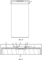
FIG. 1 is a front view of a cylindrical battery according to an embodiment of the present application. -
FIG. 2 is a sectional view of a local part A inFIG. 1 . -
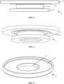
FIG. 3 is a front view of a positive pole according to an embodiment of the present application. -
FIG. 4 is a schematic structural diagram of a positive pole according to an embodiment of the present application. -
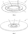
FIG. 5 is a schematic structural diagram of an upper insulation sealing member according to an embodiment of the present application. -
FIG. 6 is a schematic structural diagram of an upper insulation sealing member according to another embodiment of the present application. -
FIG. 7 is a schematic structural diagram of a lower insulation sealing member according to an embodiment of the present application. -
FIG. 8 is a schematic structural diagram of a lower insulation sealing member according to another embodiment of the present application. -
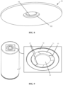
FIG. 9 is a schematic structural diagram of a case according to an embodiment of the present application. -
FIG. 10 is a front view of a cylindrical battery according to another embodiment of the present application. -
FIG. 11 is a sectional view of a local part B inFIG. 10 . -
FIG. 12 is a front view of a cylindrical battery according to another embodiment of the present application. -
FIG. 13 is a sectional view of a local part C inFIG. 12 . - Reference numerals in the drawings:
1. case; 11. protrusion block; 12. second placing groove; 13. engaging groove; 2. jellyroll; 3. positive current collecting plate; 4. positive pole; 41. first cylinder; 411. anti-slip convex block; 42. second cylinder; 43. third cylinder; 51. upper insulation sealing member; 511. first placing groove; 512. positioning groove; 513. engaging block; 52. lower insulation sealing member; 521. annular groove; 522. third placing groove; 61. first through hole; 62. second through hole; 63. third through hole; 71. first annular protrusion block; 72. second annular protrusion block; 8. negative current collecting plate; and 9. negative cap. - It is to be understood that the embodiments described herein are intended to illustrate rather than limiting the present application.
- In the description of the application, it is to be appreciated that the orientation or position relationship indicated by terms such as "center", "longitudinal", "transverse", "length", "width", "thickness", "over", "below", "front", "back", "left", "right", "vertical", "horizontal", "top", "bottom", "inside", "outside", "clockwise" or "counterclockwise" is based on the orientation or position relationship shown in the drawings, which is only for the convenience of describing the present application and simplifying the description, rather than indicating or implying that the device or element referred to must have a specific orientation, be configured and operated in a specific orientation, so it cannot be understood as a limitation to the present application. Furthermore, the terms "first" and "second" are only used for description purposes and cannot be understood as indicating or implying relative importance or implicitly indicating the number of indicated technical features. Thus, the features defined as "first" and "second" can explicitly or implicitly include one or more of the described features. In the description of the present application, "multiple" means two or more, unless otherwise specifically defined.
- In the description of the present application, it is to be noted that, unless otherwise expressly specified and limited, the terms "mounting", "connected to each other", "connected" are to be construed in a broad sense, for example, as permanently connected or detachably connected or integrally connected; mechanically connected; directly connected to each other or indirectly connected to each other via an intermediary; or internally connection of two components or interaction relationship between two components. For those of ordinary skill in the art, specific meanings of the preceding terms in the present application may be construed based on specific situations.
- In the present application, unless otherwise expressly specified and limited, when a first feature is described as "above" or "below" a second feature, the first feature and the second feature may be in direct contact, or be in contact via another feature between the two features. Moreover, when the first feature is described as "on", "above" or "over" the second feature, the first feature is right on, above or over the second feature or the first feature is obliquely on, above or over the second feature, or the first feature is simply at a higher level than the second feature. When the first feature is described as "under", "below" or "underneath" the second feature, the first feature is right under, below or underneath the second feature or the first feature is obliquely under, below or underneath the second feature, or the first feature is simply at a lower level than the second feature.
- As shown in
FIG. 1 to FIG. 2 , an embodiment of the present application provides a cylindrical battery, which includes acase 1, ajellyroll 2, a positivecurrent collecting plate 3, apositive pole 4 and an insulation sealing member. Thecase 1 is a cylindrical groove structure, thepositive pole 4 is penetrated into thecase 1 via an end face, remote from a groove opening of thecase 1, of thecase 1, thepositive pole 4 is riveted to thecase 1, and the insulation sealing member is arranged between thepositive pole 4 and thecase 1. Thejellyroll 2 and the positivecurrent collecting plate 3 are arranged inside thecase 1, an end, located inside the groove structure of thecase 1, of thepositive pole 4 is connected to a positive electrode terminal of thejellyroll 2 through the positivecurrent collecting plate 3, and thepositive pole 4 is positively charged. The cylindrical battery is a cylindrical full-tab battery, thejellyroll 2 is a full-tab structure and is prepared by winding, and an end face, remote from thepositive pole 4, of the positivecurrent collecting plate 3 is connected to the positive electrode terminal of thejellyroll 2 by laser end-face-welding. As shown inFIG. 3 to FIG. 4 , thepositive pole 4 is an integrated structure in which three cylinders are coaxially superimposed. The three cylinders are respectively, from top to bottom, afirst cylinder 41 serving as a conductive terminal, asecond cylinder 42 serving as a connecting rod, and athird cylinder 43 serving as a connecting terminal. Thethird cylinder 43 has a diameter smaller than the diameter of thefirst cylinder 41 and larger than the diameter of thesecond cylinder 42. Thethird cylinder 43 is arranged inside thecase 1, and thefirst cylinder 41 is arranged outside thecase 1. Thesecond cylinder 42 sequentially passes through an upperinsulation sealing member 51, thecase 1, and a lowerinsulation sealing member 52. - As shown in
FIG. 5 , the insulation sealing member includes the upperinsulation sealing member 51 and the lowerinsulation sealing member 52, the upperinsulation sealing member 51 is provided with a first throughhole 61, the lowerinsulation sealing member 52 is provided with a third throughhole 63, thecase 1 is provided with a second throughhole 62, and thesecond cylinder 42 passes through the first throughhole 61, the second throughhole 62, and the third throughhole 63 sequentially. The central axis of thepositive pole 4, the central axis of the first throughhole 61, the central axis of the second throughhole 62, and the central axis of the third throughhole 63 all coincide. - As shown in
FIG. 5 to FIG. 6 , an end face, close to thefirst cylinder 41, of the upperinsulation sealing member 51 is provided with afirst placing groove 511, a central portion of a groove bottom face of thefirst placing groove 511 is provided with an opening of the first throughhole 61, and an outer sidewall of thefirst cylinder 41 is in close contact with an inner sidewall of thefirst placing groove 511. An end face, in contact with the groove bottom face of the first placing groove, of thefirst cylinder 41 is provided with an annular anti-slipconvex block 411, and the central axis of the anti-slipconvex block 411 coincides with the central axis of thefirst cylinder 41. Thefirst cylinder 41 has a tendency to press the upperinsulation sealing member 51 towards thecase 1 in a vertical direction, so that the anti-slipconvex block 411 may be in close contact with the groove bottom face of thefirst placing groove 511, thereby increasing the sealing performance between thefirst cylinder 41 and the upperinsulation sealing member 51, and preventing thepositive pole 4 from rotating about the central axis of thepositive pole 4. - As shown in
FIG. 9 to FIG. 10 , an end face of thecase 1 remote from its groove opening is provided with asecond placing groove 12, a central portion of a groove bottom face of thesecond placing groove 12 is provided with an opening of the second throughhole 62, the groove bottom face of thesecond placing groove 12 is provided with aprotrusion block 11, theprotrusion block 11 is arranged circumferentially about the central axis of the second throughhole 62, and theprotrusion block 11 is provided with threeengaging grooves 13. - An end face, close to the
case 1, of the upperinsulation sealing member 51 is provided with apositioning groove 512 fitted with and connected to theprotrusion block 11, a groove bottom face of thepositioning groove 512 is provided with an opening of the first throughhole 61, an edge of the opening is provided with a firstannular protrusion block 71, and the groove bottom face of thepositioning groove 512 is further provided with engagingblocks 513 fitted with and engaged with the engaginggrooves 13 respectively. An outer sidewall of the upperinsulation sealing member 51 is in contact with an inner sidewall of thesecond placing groove 12. A portion, other than thepositioning groove 512, of the end face, close to thecase 1, of the upperinsulation sealing member 51 is in contact with the groove bottom face of thesecond placing groove 12, and theprotrusion block 11 is tightly connected to thepositioning groove 512, so that the structure can ensure the sealing performance of the connection between the upperinsulation sealing member 51 and thecase 1. - The engaging
grooves 13 are fitted with and connected to the engagingblocks 513 in an engagement manner, and the engaged connection structure is capable of obstructing rotation of thepositive pole 4 about its central axis. - As shown in
FIG. 7 to FIG. 8 , an end face, remote from the positivecurrent collecting plate 3, of the lowerinsulation sealing member 52 is provided with an opening of the third throughhole 63, an edge of the opening is provided with a secondannular protrusion block 72, the end face is further provided with anannular groove 521, and the central axis of theannular groove 521 coincides with the central axis of the third throughhole 63. - As shown in
FIG. 2 , thesecond placing groove 12 of thecase 1 forms an annular protrusion protruding toward the inside of the case, and the annular protrusion is fitted with and connected to theannular groove 521, to prevent the lowerinsulation sealing member 52 located inside thecase 1 from moving in a horizontal direction. - As shown in
FIG. 8 , an end face, close to the positivecurrent collecting plate 3, of the lowerinsulation sealing member 52 is provided with athird placing groove 522, thethird cylinder 43 is located in thethird placing groove 522 and is in contact with a groove bottom face of thethird placing groove 522, and thethird cylinder 43 has a tendency to press the lowerinsulation sealing member 52 towards the case in the vertical direction, thereby fixing the lowerinsulation sealing member 52 in the vertical direction. - As shown in
FIG. 2 , a maximum width of the positivecurrent collecting plate 3 is larger than the width of thethird placing groove 522 but smaller than the width of the lowerinsulation sealing member 52, and the positivecurrent collecting plate 3 is in close contact with the lowerinsulation sealing member 52. The lowerinsulation sealing member 52 prevents the positivecurrent collecting plate 3 and the case from contacting in the vertical direction and the battery short circuit caused by the contacting of the positivecurrent collecting plate 3 and the case, and in this embodiment, the riveting structure of thepositive pole 4 to thecase 1 in turn prevents the positivecurrent collecting plate 3 and the case from contacting in the horizontal direction and the battery short circuit caused by the contacting of the positivecurrent collecting plate 3 and the case. - As shown in
FIG. 2 , the firstannular protrusion block 71 and the secondannular protrusion block 72 extend oppositely in the vertical direction into the second throughhole 62 and are filled between the outer sidewall of thesecond cylinder 42 and the inner sidewall of the second throughhole 62. The firstannular protrusion block 71 and the secondannular protrusion block 72 both function to prevent thesecond cylinder 42 from contacting thecase 1, moreover, the outer sidewall of thesecond cylinder 42 presses the firstannular protrusion block 71 and the secondannular protrusion block 72 toward the inner sidewall of the second throughhole 62, thereby increasing the friction force between thesecond cylinder 42 and the firstannular protrusion block 71 as well as the friction force between thesecond cylinder 42 and the secondannular protrusion block 72, and thereby preventing thepositive pole 4 from rotating. - By the arrangement of the above structure, the
positive pole 4 can be prevented from rotating, and thepositive pole 4 is further fixed in the vertical direction and the horizontal direction. By the structural design of the cylindrical battery, the stability of the cylindrical battery can be significantly improved. - As shown in
FIG. 10 to FIG. 11 , a cylindrical battery is provided according to this embodiment, this cylindrical battery differs from the cylindrical battery according to the first embodiment in that the lowerinsulation sealing member 52 of the cylindrical battery according to this embodiment is not provided with the secondannular protrusion block 72, and the upperinsulation sealing member 51 of the cylindrical battery according to this embodiment is provided with a firstannular protrusion block 71. The firstannular protrusion block 71 extends into the second throughhole 62 and is filled between the outer sidewall of thesecond cylinder 42 and the inner sidewall of the second throughhole 62, and moreover, the outer sidewall of thesecond cylinder 42 compresses the firstannular protrusion block 71 toward the inner sidewall of the second throughhole 62 in the horizontal direction, thereby increasing the friction force between thesecond cylinder 42 and the firstannular protrusion block 71, and thereby preventing thepositive pole 4 from rotating. - The multiple technical features of the embodiments described above may be combined arbitrarily. For the sake of brevity, not all possible combinations of the multiple technical features of the embodiment described above are described. However, the combinations of these technical features should be considered to be within the scope of the present description as long as no contradictions exist in their combinations.
- In the present application, for facilitating the description, an end, located outside the
case 1, of thepositive pole 4 is referred to as "a conductive terminal", an end, located inside thecase 1, of thepositive pole 4 is referred to as "a connecting terminal", a connecting rod is arranged between the conductive terminal and the connecting terminal, and the connecting terminal is connected to the positivecurrent collecting plate 3. - The insulation sealing member includes an upper
insulation sealing member 51 and a lowerinsulation sealing member 52, the upperinsulation sealing member 51 is arranged outside thecase 1 and is engaged with and connected to thecase 1, and the lowerinsulation sealing member 52 is arranged inside thecase 1. The upperinsulation sealing member 51 is arranged between an end face of thecase 1 and the conductive terminal, and the lowerinsulation sealing member 52 is arranged between the groove bottom face inside thecase 1 and the positivecurrent collecting plate 3. The connecting rod sequentially passes through the upperinsulation sealing member 51, thecase 1 and the lowerinsulation sealing member 52. - At least one of the upper
insulation sealing member 51 and the lowerinsulation sealing member 52 is provided with an annular protrusion block, the annular protrusion block fits closely against an outer sidewall of a portion, passing through thecase 1, of thepositive pole 4, and the outer sidewall of the portion, passing through thecase 1, of thepositive pole 4 can press the annular protrusion block towards an inner sidewall of a portion, being passed through, of thecase 4. - As shown in
FIG. 12 to FIG. 13 , in an embodiment of the present application, the cylindrical battery further includes a negativecurrent collecting plate 8 and anegative cap 9, the groove opening of thecase 1 is connected to thenegative cap 9 in a sealed manner, thenegative cap 9 is connected to a negative electrode terminal of thejellyroll 2 through the negativecurrent collecting plate 8, therefore, thenegative cap 9 is negatively charged. Since thecase 1 is made of a non-electrically conductive material, thecase 1 is not charged. In this case, the functions of the insulation sealing member include: sealing the portion, passing through thecase 1, of thepositive pole 4; serving as a buffer layer to prevent contacting and rubbing between thepositive pole 4 and thecase 1 and the damage resulted from the contacting and rubbing. Thepositive pole 4 serves as a positive connection terminal, thenegative cap 9 serves as a negative connection terminal, and the positive connection terminal and the negative connection terminal are arranged respectively on two end faces of the cylindrical battery. - In an embodiment, the
case 1 is electrically connected to the negativecurrent collecting plate 8. - In an embodiment, the cylindrical battery further includes a negative
current collecting plate 8 and anegative cap 9, the groove opening of thecase 1 is connected to thenegative cap 9 in a sealed manner, thenegative cap 9 is connected to the negative terminal of thejellyroll 2 through the negativecurrent collecting plate 8, therefore, thenegative cap 9 is negatively charged. Thecase 1 is made of a conductive material and is electrically connected to thenegative cap 9, therefore, thecase 1 is negatively charged. In this case, the functions of the insulation sealing member include: sealing the portion, passing through thecase 1, of thepositive pole 4; preventing contacting between thepositive pole 4 and thecase 1 and the battery short circuit resulted from the contacting. Thepositive pole 4 serves as a positive connection terminal, the end face, remote from the groove opening, of thecase 1 may serve as a negative connection terminal, and the positive connection terminal and the negative connection terminal may be arranged on the same end face of the cylindrical battery. - In another embodiment, the cylindrical battery further includes a negative
current collecting plate 8 and anegative cap 9, and the groove opening of thecase 1 is connected to thenegative cap 9 in a sealed manner. Thenegative cap 9 only serves as a sealing member, thenegative cap 9 is not connected to the negativecurrent collecting plate 8, and an insulation layer is arranged between thenegative cap 9 and thecase 1, but thecase 1 is connected to the negative electrode terminal of thejellyroll 2 through the negativecurrent collecting plate 8, therefore, thecase 1 is negatively charged. In this case, the functions of the insulation sealing member include: sealing the portion, passing through thecase 1, of thepositive pole 4; preventing contacting between thepositive pole 4 and thecase 1 and the battery short circuit resulted from the contacting. Thepositive pole 4 serves as a positive connection terminal, the end face, remote from the groove opening, of thecase 1 may serve as a negative connection terminal, and the positive connection terminal and the negative connection terminal may be arranged on the same end face of the cylindrical battery. - According to the present application, the
positive pole 4 is prevented by such means from rotating: the upperinsulation sealing member 51 is engaged with and connected to the end face of thecase 1, the engaged connection structure includes the engaginggrooves 13 arranged circumferentially about the connecting rod and the engagingblocks 513, and the engaginggrooves 13 restrict the engagingblocks 513 from rotating circumferentially about the connecting rod; at least one of the upperinsulation sealing member 51 and the lowerinsulation sealing member 52 is provided with the annular protrusion block, the annular protrusion block fits closely against the outer sidewall of the portion, passing through thecase 1, of the connecting rod, and the outer sidewall of the portion, passing through thecase 1, of the connecting rod may press the annular protrusion block towards the inner sidewall of the portion, being passed through, of thecase 1, to thereby increasing the friction force between the annular protrusion block and the connecting rod. With the arrangement of the above structure, thepositive pole 4 can be prevented from rotating. - In the present application, both the upper
insulation sealing member 51 and the lowerinsulation sealing member 52 are made of an insulation material having elasticity. - In an embodiment, in a case where the upper
insulation sealing member 51 is provided with an annular protrusion block, the annular protrusion block includes a firstannular protrusion block 71, an end face, close to thecase 1, of the upperinsulation sealing member 51 is provided with an opening of the first throughhole 61, and an edge of the opening of the first throughhole 61 is provided with the firstannular protrusion block 71. - In a case where the lower
insulation sealing member 52 is provided with an annular protrusion block, the annular protrusion block includes a secondannular protrusion block 72, and an end face, remote from the positivecurrent collecting plate 3, of the lowerinsulation sealing member 52 is provided with an opening of the third throughhole 63, and an edge of the opening of the third throughhole 63 is provided with thesecond protrusion block 72.
Claims (11)
- A cylindrical battery, comprising a case, a positive pole and an insulation sealing member, wherein the case is a cylindrical groove structure,the positive pole is riveted to the case, and the insulation sealing member is arranged between the positive pole and the case;the insulation sealing member comprises an upper insulation sealing member and a lower insulation sealing member, the upper insulation sealing member is arranged outside the case and is engaged with and connected to the case, and the lower insulation sealing member is arranged inside the case; andat least one of the upper insulation sealing member and the lower insulation sealing member is provided with an annular protrusion block, the annular protrusion block fits closely against an outer sidewall of a portion, passing through the case, of the positive pole, and the outer sidewall of the portion, passing through the case, of the positive pole presses the annular protrusion block towards an inner sidewall of a portion, being passed through by the positive pole, of the case.
- The cylindrical battery according to claim 1, further comprising a jellyroll and a positive current collecting plate;
wherein the jellyroll and the positive current collecting plate are arranged inside the case, and a portion, located inside the case, of the positive pole is connected to a positive electrode terminal of the jellyroll through the positive current collecting plate. - The cylindrical battery according to claim 2, whereinin a case where the upper insulation sealing member is provided with the annular protrusion block, the annular protrusion block comprises a first annular protrusion block, an end face, close to the case, of the upper insulation sealing member is provided with an opening of a first through hole, and an edge of the opening of the first through hole is provided with the first annular protrusion block; andin a case where the lower insulation sealing member is provided with the annular protrusion block, the annular protrusion block comprises a second annular protrusion block, and an end face, remote from the positive current collecting plate, of the lower insulation sealing member is provided with an opening of a third through hole, and an edge of the opening of the third through hole is provided with the second protrusion block.
- The cylindrical battery according to claim 2, wherein the positive pole is an integrated structure in which three cylinders are coaxially superimposed, the three cylinders are respectively, from top to bottom, a first cylinder, a second cylinder and a third cylinder, the third cylinder has a diameter smaller than the diameter of the first cylinder and larger than the diameter of the second cylinder, the third cylinder is arranged inside the case, the first cylinder is arranged outside the case, and the second cylinder sequentially passes through the upper insulation sealing member, the case, and the lower insulation sealing member.
- The cylindrical battery according to claim 4, wherein an end face, close to the first cylinder, of the upper insulation sealing member is provided with a first placing groove, an outer sidewall of the first cylinder is in close contact with an inner sidewall of the first placing groove, and an end face, in contact with a groove bottom face of the first placing groove, of the first cylinder is provided with an annular anti-slip convex block.
- The cylindrical battery according to claim 4, wherein the case is provided with a second placing groove, a groove bottom face of the second placing groove is provided with a protrusion block, the protrusion block is arranged circumferentially around the second cylinder, and the protrusion block is provided with an engaging groove; an end face, close to the case, of the upper insulation sealing member is provided with a positioning groove fitted with and connected to the protrusion block, a groove bottom face of the positioning groove is provided with an engaging block fitted with and engaged with the engaging groove, and an outer sidewall of the upper insulation sealing member is in contact with an inner sidewall of the second placing groove.
- The cylindrical battery according to claim 8, wherein an end face, remote from the positive current collecting plate, of the lower insulation sealing member is provided with an annular groove, the second placing groove forms an annular protrusion protruding towards the inside of the case, and the annular protrusion is fitted with and connected to the annular groove.
- The cylindrical battery according to claim 4, wherein an end face, close to the positive current collecting plate, of the lower insulation sealing member is provided with a third placing groove, the third cylinder is placed in the third placing groove and is in contact with a groove bottom face of the third placing groove, a maximum width of the positive current collecting plate is larger than the width of the third placing groove and smaller than the width of the lower insulation sealing member, and the positive current collecting plate is in close contact with the lower insulation sealing member.
- The cylindrical battery according to claim 2, further comprising a negative current collecting plate and a negative cap;
wherein a groove opening of the case is connected to the negative cap in a sealed manner, and the negative cap is connected to a negative electrode terminal of the jellyroll through the negative current collecting plate. - The cylindrical battery according to claim 9, wherein the case is electrically connected to the negative current collecting plate.
- The cylindrical battery according to claim 2, further comprising a negative current collecting plate and a negative cap;
wherein a groove opening of the case is connected to the negative cap in a sealed manner, the negative cap is not connected to the negative current collecting plate, an insulation layer is arranged between the negative cap and the case, and the case is connected to a negative electrode terminal of the jellyroll through the negative current collecting plate.
Priority Applications (1)
| Application Number | Priority Date | Filing Date | Title |
|---|---|---|---|
| HUU2500014U HU5946U (en) | 2021-05-21 | 2022-05-20 | Cylindrical battery |
Applications Claiming Priority (2)
| Application Number | Priority Date | Filing Date | Title |
|---|---|---|---|
| CN202121100824.8U CN215578778U (en) | 2021-05-21 | 2021-05-21 | A new type of cylindrical battery |
| PCT/CN2022/094118 WO2022242748A1 (en) | 2021-05-21 | 2022-05-20 | Cylindrical battery |
Publications (2)
| Publication Number | Publication Date |
|---|---|
| EP4152493A1 true EP4152493A1 (en) | 2023-03-22 |
| EP4152493A4 EP4152493A4 (en) | 2025-03-12 |
Family
ID=79862832
Family Applications (1)
| Application Number | Title | Priority Date | Filing Date |
|---|---|---|---|
| EP22804067.1A Pending EP4152493A4 (en) | 2021-05-21 | 2022-05-20 | Cylindrical battery |
Country Status (6)
| Country | Link |
|---|---|
| US (1) | US20240250355A1 (en) |
| EP (1) | EP4152493A4 (en) |
| CN (1) | CN215578778U (en) |
| DE (1) | DE202022003049U1 (en) |
| HU (1) | HU5946U (en) |
| WO (1) | WO2022242748A1 (en) |
Cited By (2)
| Publication number | Priority date | Publication date | Assignee | Title |
|---|---|---|---|---|
| EP4576295A1 (en) * | 2023-12-21 | 2025-06-25 | SK On Co., Ltd. | Battery cell |
| WO2025208434A1 (en) * | 2024-04-03 | 2025-10-09 | 宁德时代新能源科技股份有限公司 | Battery cell, battery, and electric device |
Families Citing this family (9)
| Publication number | Priority date | Publication date | Assignee | Title |
|---|---|---|---|---|
| CN215578778U (en) * | 2021-05-21 | 2022-01-18 | 湖北亿纬动力有限公司 | A new type of cylindrical battery |
| CN113346168A (en) * | 2021-05-21 | 2021-09-03 | 湖北亿纬动力有限公司 | Cylindrical battery with novel structure |
| WO2023018154A1 (en) * | 2021-08-13 | 2023-02-16 | 주식회사 엘지에너지솔루션 | Cylindrical secondary battery cell, and battery pack and vehicle including same |
| CN217589342U (en) * | 2022-06-02 | 2022-10-14 | 湖北亿纬动力有限公司 | Battery, battery module and battery pack |
| KR102554328B1 (en) * | 2022-10-05 | 2023-07-11 | 삼성에스디아이 주식회사 | Cylindrical secondary battery |
| CN219203322U (en) * | 2022-12-29 | 2023-06-16 | 远景动力技术(江苏)有限公司 | A cylindrical battery and electronic equipment |
| CN219203417U (en) * | 2023-01-12 | 2023-06-16 | 宁德时代新能源科技股份有限公司 | Battery monomer, battery and power consumption device |
| CN115911691B (en) * | 2023-03-14 | 2023-05-26 | 广汽埃安新能源汽车股份有限公司 | Top cap subassembly, battery monomer and power battery package |
| KR102853427B1 (en) * | 2023-06-09 | 2025-09-02 | 삼성에스디아이 주식회사 | Secondary battery |
Family Cites Families (15)
| Publication number | Priority date | Publication date | Assignee | Title |
|---|---|---|---|---|
| JP4375660B2 (en) * | 2003-08-01 | 2009-12-02 | 日立マクセル株式会社 | Sealed battery |
| KR100686839B1 (en) * | 2005-05-17 | 2007-02-26 | 삼성에스디아이 주식회사 | Secondary battery |
| JP5795937B2 (en) * | 2011-10-25 | 2015-10-14 | 日立オートモティブシステムズ株式会社 | Secondary battery |
| KR101798926B1 (en) * | 2015-01-26 | 2017-11-17 | 주식회사 엘지화학 | Secondary Battery Having Insulative Member with Improved Structural Stability against External Force |
| CN205645909U (en) * | 2016-05-24 | 2016-10-12 | 宁德时代新能源科技股份有限公司 | Battery top cap subassembly reaches battery that contains this subassembly |
| JP6868400B2 (en) * | 2017-01-17 | 2021-05-12 | Fdk株式会社 | Cylindrical battery enclosure, tubular battery |
| CN107302065A (en) * | 2017-06-26 | 2017-10-27 | 湖南三迅新能源科技有限公司 | Battery cover board and its processing method |
| CN207183329U (en) * | 2017-07-28 | 2018-04-03 | 深圳市欣迪盟新能源科技股份有限公司 | Battery cover board and battery |
| CN209658246U (en) * | 2019-05-14 | 2019-11-19 | 宁德时代新能源科技股份有限公司 | Cap assembly and secondary cell |
| CN212062478U (en) * | 2020-06-15 | 2020-12-01 | 苏州凌威新能源科技有限公司 | Battery cover plate assembly and battery cell |
| KR102846144B1 (en) * | 2021-02-19 | 2025-08-14 | 주식회사 엘지에너지솔루션 | Battery cell, and battery pack and vehicle including the same |
| CN217788661U (en) * | 2021-02-19 | 2022-11-11 | 株式会社Lg新能源 | Secondary battery, collector plate applied to secondary battery, battery pack comprising secondary battery, and automobile |
| CN113270693A (en) * | 2021-05-17 | 2021-08-17 | 微宏动力系统(湖州)有限公司 | Full-tab pole piece and winding battery |
| CN113346201A (en) * | 2021-05-21 | 2021-09-03 | 湖北亿纬动力有限公司 | Cylindrical battery, battery module and battery pack |
| CN215578778U (en) * | 2021-05-21 | 2022-01-18 | 湖北亿纬动力有限公司 | A new type of cylindrical battery |
-
2021
- 2021-05-21 CN CN202121100824.8U patent/CN215578778U/en active Active
-
2022
- 2022-05-20 WO PCT/CN2022/094118 patent/WO2022242748A1/en not_active Ceased
- 2022-05-20 EP EP22804067.1A patent/EP4152493A4/en active Pending
- 2022-05-20 HU HUU2500014U patent/HU5946U/en unknown
- 2022-05-20 US US18/014,062 patent/US20240250355A1/en active Pending
- 2022-05-20 DE DE202022003049.5U patent/DE202022003049U1/en active Active
Cited By (2)
| Publication number | Priority date | Publication date | Assignee | Title |
|---|---|---|---|---|
| EP4576295A1 (en) * | 2023-12-21 | 2025-06-25 | SK On Co., Ltd. | Battery cell |
| WO2025208434A1 (en) * | 2024-04-03 | 2025-10-09 | 宁德时代新能源科技股份有限公司 | Battery cell, battery, and electric device |
Also Published As
| Publication number | Publication date |
|---|---|
| DE202022003049U1 (en) | 2024-07-18 |
| CN215578778U (en) | 2022-01-18 |
| WO2022242748A1 (en) | 2022-11-24 |
| HU5946U (en) | 2025-10-28 |
| EP4152493A4 (en) | 2025-03-12 |
| US20240250355A1 (en) | 2024-07-25 |
Similar Documents
| Publication | Publication Date | Title |
|---|---|---|
| US20240250355A1 (en) | Cylindrical battery | |
| CN113346168A (en) | Cylindrical battery with novel structure | |
| EP4152492A1 (en) | Battery | |
| JP7320758B2 (en) | battery module | |
| US12244024B2 (en) | Top cover assembly and secondary battery | |
| US10665827B2 (en) | Cap assembly for a second battery and second battery | |
| US12119503B2 (en) | Cap assembly and secondary battery | |
| US7678498B2 (en) | Nonaqueous electrolyte secondary battery | |
| SE2250985A1 (en) | Power battery cover and power battery | |
| KR101288531B1 (en) | Ultra-capacitor assembly | |
| US20120092808A1 (en) | High voltage electric double layer capacitor device and methods of manufacture | |
| CN107112148A (en) | Improve the apparatus for storing electrical energy of the mounting structure at back panel wiring end | |
| JP4451654B2 (en) | Lithium secondary battery | |
| US12100550B2 (en) | Electrochemical energy storage device | |
| KR20160100673A (en) | Battery pack | |
| JP6601116B2 (en) | Terminal structure, power storage cell, and power storage module | |
| JP6149692B2 (en) | Terminal structure | |
| JP3797813B2 (en) | Electric double layer capacitor | |
| JPH1126322A (en) | Electric double layer capacitor | |
| CN210866255U (en) | Safety battery | |
| KR20220049193A (en) | Ultra Capacitor | |
| KR101803864B1 (en) | Insulation element and electric energy storage apparatus comprising the same | |
| JPH1126321A (en) | Electric double layer capacitor | |
| JP2005026090A (en) | Electrochemical cell | |
| CN223321351U (en) | Battery casings, batteries, battery packs and electrical equipment |
Legal Events
| Date | Code | Title | Description |
|---|---|---|---|
| STAA | Information on the status of an ep patent application or granted ep patent |
Free format text: STATUS: THE INTERNATIONAL PUBLICATION HAS BEEN MADE |
|
| PUAI | Public reference made under article 153(3) epc to a published international application that has entered the european phase |
Free format text: ORIGINAL CODE: 0009012 |
|
| STAA | Information on the status of an ep patent application or granted ep patent |
Free format text: STATUS: REQUEST FOR EXAMINATION WAS MADE |
|
| 17P | Request for examination filed |
Effective date: 20221216 |
|
| AK | Designated contracting states |
Kind code of ref document: A1 Designated state(s): AL AT BE BG CH CY CZ DE DK EE ES FI FR GB GR HR HU IE IS IT LI LT LU LV MC MK MT NL NO PL PT RO RS SE SI SK SM TR |
|
| DAV | Request for validation of the european patent (deleted) | ||
| DAX | Request for extension of the european patent (deleted) | ||
| A4 | Supplementary search report drawn up and despatched |
Effective date: 20250212 |
|
| RIC1 | Information provided on ipc code assigned before grant |
Ipc: H01M 50/186 20210101ALI20250206BHEP Ipc: H01M 50/193 20210101ALI20250206BHEP Ipc: H01M 50/559 20210101ALI20250206BHEP Ipc: H01M 50/171 20210101ALI20250206BHEP Ipc: H01M 50/167 20210101ALI20250206BHEP Ipc: H01M 50/152 20210101ALI20250206BHEP Ipc: H01M 50/107 20210101ALI20250206BHEP Ipc: H01M 50/148 20210101ALI20250206BHEP Ipc: H01M 10/04 20060101ALI20250206BHEP Ipc: H01M 50/548 20210101ALI20250206BHEP Ipc: H01M 50/198 20210101ALI20250206BHEP Ipc: H01M 50/184 20210101ALI20250206BHEP Ipc: H01M 50/188 20210101ALI20250206BHEP Ipc: H01M 50/179 20210101AFI20250206BHEP |