EP4152492A1 - Battery - Google Patents
Battery Download PDFInfo
- Publication number
- EP4152492A1 EP4152492A1 EP22804063.0A EP22804063A EP4152492A1 EP 4152492 A1 EP4152492 A1 EP 4152492A1 EP 22804063 A EP22804063 A EP 22804063A EP 4152492 A1 EP4152492 A1 EP 4152492A1
- Authority
- EP
- European Patent Office
- Prior art keywords
- case
- face
- cap plate
- annular protrusion
- current collector
- Prior art date
- Legal status (The legal status is an assumption and is not a legal conclusion. Google has not performed a legal analysis and makes no representation as to the accuracy of the status listed.)
- Pending
Links
Images



Classifications
-
- H—ELECTRICITY
- H01—ELECTRIC ELEMENTS
- H01M—PROCESSES OR MEANS, e.g. BATTERIES, FOR THE DIRECT CONVERSION OF CHEMICAL ENERGY INTO ELECTRICAL ENERGY
- H01M50/00—Constructional details or processes of manufacture of the non-active parts of electrochemical cells other than fuel cells, e.g. hybrid cells
- H01M50/10—Primary casings; Jackets or wrappings
- H01M50/147—Lids or covers
- H01M50/166—Lids or covers characterised by the methods of assembling casings with lids
- H01M50/169—Lids or covers characterised by the methods of assembling casings with lids by welding, brazing or soldering
-
- H—ELECTRICITY
- H01—ELECTRIC ELEMENTS
- H01M—PROCESSES OR MEANS, e.g. BATTERIES, FOR THE DIRECT CONVERSION OF CHEMICAL ENERGY INTO ELECTRICAL ENERGY
- H01M50/00—Constructional details or processes of manufacture of the non-active parts of electrochemical cells other than fuel cells, e.g. hybrid cells
- H01M50/10—Primary casings; Jackets or wrappings
- H01M50/102—Primary casings; Jackets or wrappings characterised by their shape or physical structure
- H01M50/107—Primary casings; Jackets or wrappings characterised by their shape or physical structure having curved cross-section, e.g. round or elliptic
-
- H—ELECTRICITY
- H01—ELECTRIC ELEMENTS
- H01M—PROCESSES OR MEANS, e.g. BATTERIES, FOR THE DIRECT CONVERSION OF CHEMICAL ENERGY INTO ELECTRICAL ENERGY
- H01M50/00—Constructional details or processes of manufacture of the non-active parts of electrochemical cells other than fuel cells, e.g. hybrid cells
- H01M50/10—Primary casings; Jackets or wrappings
- H01M50/147—Lids or covers
- H01M50/148—Lids or covers characterised by their shape
- H01M50/152—Lids or covers characterised by their shape for cells having curved cross-section, e.g. round or elliptic
-
- H—ELECTRICITY
- H01—ELECTRIC ELEMENTS
- H01M—PROCESSES OR MEANS, e.g. BATTERIES, FOR THE DIRECT CONVERSION OF CHEMICAL ENERGY INTO ELECTRICAL ENERGY
- H01M50/00—Constructional details or processes of manufacture of the non-active parts of electrochemical cells other than fuel cells, e.g. hybrid cells
- H01M50/50—Current conducting connections for cells or batteries
- H01M50/531—Electrode connections inside a battery casing
-
- H—ELECTRICITY
- H01—ELECTRIC ELEMENTS
- H01M—PROCESSES OR MEANS, e.g. BATTERIES, FOR THE DIRECT CONVERSION OF CHEMICAL ENERGY INTO ELECTRICAL ENERGY
- H01M50/00—Constructional details or processes of manufacture of the non-active parts of electrochemical cells other than fuel cells, e.g. hybrid cells
- H01M50/50—Current conducting connections for cells or batteries
- H01M50/543—Terminals
- H01M50/545—Terminals formed by the casing of the cells
-
- H—ELECTRICITY
- H01—ELECTRIC ELEMENTS
- H01M—PROCESSES OR MEANS, e.g. BATTERIES, FOR THE DIRECT CONVERSION OF CHEMICAL ENERGY INTO ELECTRICAL ENERGY
- H01M50/00—Constructional details or processes of manufacture of the non-active parts of electrochemical cells other than fuel cells, e.g. hybrid cells
- H01M50/50—Current conducting connections for cells or batteries
- H01M50/543—Terminals
- H01M50/552—Terminals characterised by their shape
- H01M50/559—Terminals adapted for cells having curved cross-section, e.g. round, elliptic or button cells
-
- H—ELECTRICITY
- H01—ELECTRIC ELEMENTS
- H01M—PROCESSES OR MEANS, e.g. BATTERIES, FOR THE DIRECT CONVERSION OF CHEMICAL ENERGY INTO ELECTRICAL ENERGY
- H01M50/00—Constructional details or processes of manufacture of the non-active parts of electrochemical cells other than fuel cells, e.g. hybrid cells
- H01M50/50—Current conducting connections for cells or batteries
- H01M50/543—Terminals
- H01M50/564—Terminals characterised by their manufacturing process
- H01M50/566—Terminals characterised by their manufacturing process by welding, soldering or brazing
-
- Y—GENERAL TAGGING OF NEW TECHNOLOGICAL DEVELOPMENTS; GENERAL TAGGING OF CROSS-SECTIONAL TECHNOLOGIES SPANNING OVER SEVERAL SECTIONS OF THE IPC; TECHNICAL SUBJECTS COVERED BY FORMER USPC CROSS-REFERENCE ART COLLECTIONS [XRACs] AND DIGESTS
- Y02—TECHNOLOGIES OR APPLICATIONS FOR MITIGATION OR ADAPTATION AGAINST CLIMATE CHANGE
- Y02E—REDUCTION OF GREENHOUSE GAS [GHG] EMISSIONS, RELATED TO ENERGY GENERATION, TRANSMISSION OR DISTRIBUTION
- Y02E60/00—Enabling technologies; Technologies with a potential or indirect contribution to GHG emissions mitigation
- Y02E60/10—Energy storage using batteries
Definitions
- the present application relates to the field of batteries, for example, to a battery.
- the cylindrical lithium-ion battery in the related art is a cylindrical lithium-ion battery provided with a cap plate, and the connection of the cap plate to a case of the battery in assembling has a poor reliability, the cap plate has a risk of being cracked or disconnected when it is under certain conditions such as being subjected to vibration, pressure, therefore, there is a significant potential safety hazard.
- a battery is provided according to the present application, and the battery has high connecting strength between a cap plate and a case and excellent hermetic performance.
- a battery which includes a case and a cap plate.
- the case is a cylindrical groove structure, a top end face, facing towards the case, of the cap plate is provided with an annular protrusion, the annular protrusion has a central axis coinciding with the central axis of the cap plate, an edge of the top end face of the cap plate is provided with a first welding platform face, the first welding platform face is arranged circumferentially around the annular protrusion, and an outer sidewall of the annular protrusion and the first welding platform face constitute a stepped face.
- the annular protrusion enters the interior of the case via an annular bottom end face of the case, and the annular bottom end face of the case is in contact with the first welding platform face and connected to the first welding platform face by laser welding.
- orientation or position relationship indicated by terms such as “center”, “longitudinal”, “transverse”, “length”, “width”, “thickness”, “over”, “below”, “front”, “back”, “left”, “right”, “vertical”, “horizontal”, “top”, “bottom”, “inside”, “outside”, “clockwise” or “counterclockwise” is based on the orientation or position relationship shown in the drawings, which is only for the convenience of describing the present application and simplifying the description, rather than indicating or implying that the device or element referred to must have a specific orientation, be configured and operated in a specific orientation, so it cannot be understood as a limitation to the present application.
- first and second are only used for description purposes and cannot be understood as indicating or implying relative importance or implicitly indicating the number of indicated technical features.
- the features defined as “first” and “second” can explicitly or implicitly include one or more of the described features.
- “multiple” means two or more, unless otherwise specifically defined.
- first feature and the second feature may be in direct contact, or be in contact via another feature between the two features.
- first feature is described as “on”, “above” or “over” the second feature, the first feature is right on, above or over the second feature or the first feature is obliquely on, above or over the second feature, or the first feature is simply at a higher level than the second feature.
- the first feature When the first feature is described as “under”, “below” or “underneath” the second feature, the first feature is right under, below or underneath the second feature or the first feature is obliquely under, below or underneath the second feature, or the first feature is simply at a lower level than the second feature.
- a battery with a novel structure includes a case 2 and a cap plate 1, specifically, the case 2 is a cylindrical groove structure, a winding core 3 and a negative current collector 4 are arranged in the case 2, and an annular bottom end face of the case 2 is connected to a top end face, facing towards the case, of the cap plate 1 by laser welding.
- the cap plate 1 has a diameter equal to a maximum diameter of the case 2.
- the top end face, facing towards the case 2, of the cap plate 1 is provided with an annular protrusion 11, and the annular protrusion 11 has a central axis coinciding with the central axis of the cap plate 1.
- An edge of the top end face, facing towards the case 2, of the cap plate 1 is provided with a first welding platform face 12, the first welding platform face 12 is arranged circumferentially around the annular protrusion 11, and an outer sidewall of the annular protrusion 11 and the first welding platform face 12 constitute a stepped face.
- the annular protrusion 11 enters the interior of the case 2 via the annular bottom end face of the case 2, and an outer sidewall of the annular protrusion 11 comes into contact with an inner sidewall of the case 2.
- the annular bottom end face of the case 2 is in contact with the first welding platform face 12 and is connected to the first welding platform face 12 by laser welding, so that the structure is firm and has a good hermetic performance.
- a top end face of the annular protrusion 11 is provided with a second welding platform face 13, and an end face, remote from the cap plate 1, of the negative current collector 4 is connected to a negative electrode of the winding core 3.
- Four supporting blocks 5 are arranged between an end face, close to the cap plate 1, of the current collector 4 and the second welding platform face 13 of the annular protrusion 11, the four supporting blocks 5 are circumferentially distributed uniformly about the central axis of the cap plate 1, the supporting blocks 5 are made of a conductive material, and ends, remote from the negative current collector 4, of the supporting blocks 5 are connected to the second welding platform face 13 by welding.
- Ends, remote from the cap plate 1, of the support blocks 5 are arranged integrally with the negative current collector 4.
- the ends, remote from the cap plate 1, of the support blocks 5 are connected to the negative current collector 4 by welding.
- the top end face of the annular protrusion is provided with the second welding platform face.
- the end face, remote from the cap plate, of the negative current collector is connected to the negative electrode of the winding core, and the multiple supporting blocks are provided between the end face, close to the cap plate, of the negative current collector and the second welding platform face of the annular protrusion.
- the supporting blocks are made of a conductive material, the ends, remote from the negative current collector, of the supporting blocks are connected to the second welding platform face by welding, and another ends of the supporting blocks may be arranged integrally with the negative current collector or may be connected to the negative current collector by welding.
- the cap plate is rigidly connected to the negative current collector through the supporting blocks. A positive current collector, the winding core and the negative current collector arranged in a stacked manner are clamped between a groove bottom face of the case and the supporting blocks.
- the outer sidewall of the annular protrusion when the cap plate and the case are in a connected state, the outer sidewall of the annular protrusion is in contact with the inner sidewall of the case, so that the annular protrusion can have functions of positioning and connection.
- the present application provides a battery with a novel structure, the battery has high connecting strength between the cap plate and the case and good hermetic performance, and the case does not need to be subjected to the groove-rolling process resulted in internal space loss of the case, so that the utilization rate of the space inside the case is high, and the utilization rate of the space inside the case can be further improved by reducing the height of the supporting blocks.
- the negative current collector functions as both a sealing terminal, for sealing the opening of the tank, and a negative conductive terminal.
- the outer sidewall of the annular protrusion is connected to the inner sidewall of the case by laser welding.
- the battery further includes a winding core and a negative current collector, and the winding core and the negative current collector are located inside the case.
- the cap plate includes a current collecting region 14 and a welding region 15, the current collecting region 14 is arranged to collect current of the winding core, and the welding region 15 is configured to be connected to the cap plate by welding.
- the current collecting region 14 is an annular protrusion region provided on the top end face, facing towards the case, of the cap plate, and the current collecting region 14 has a central axis coinciding with the central axis of the cap plate, and is arranged to be electrically connected to the negative collector current of the case inside.
- the welding region 15 is another annular protrusion region provided on the top end face, facing towards the case, of the cap plate, and the welding region 15 has a central axis also coinciding with the central axis of the cap plate, and is configured for welding the battery to seal the battery.
- the negative current collector is a planar structure or a stereoscopic structure, for example, a circular planar structure or an irregular stereoscopic structure, and the negative current collector is configured to collect current of the winding core and achieve electrical connection to the cap plate.
- the height of the annular protrusion ranges from 0.1mm to 3mm.
- the annular protrusion has a diameter smaller than an inner diameter of the case by 0.05mm to 0.2mm.
- An inclination face, in contact with the case, of the annular protrusion may have an inclination angle ranging from 1° to 5°.
- the case includes a cylindrical barrel and a groove structure located at the top of the case, and the groove structure is annular-shaped.
- the battery further includes a positive terminal 6 and an insulation sealing member 8, the top of the case is provided with a through hole 21, the through hole 21 is configured for mounting the positive terminal 6 and the insulation sealing member 8, and the through hole 21 has a central axis coinciding with the central axis of the cap plate.
- the central region of the top of the case is the positive terminal 6, and the positive terminal 6 and the negative region are located at a same side of the top of the case.
- the battery further includes a positive current collector 7, the positive current collector 7 is electrically connected to the positive terminal 6, and the negative current collector is electrically connected to the cap plate.
- the annular bottom end face of the case is fitted with a peripheral region of the annular protrusion of the cap plate, and the cap plate is connected to the case in a sealed manner by laser welding, thus, the assembly of the battery is completed.
- the height of the battery ranges from 80mm to 130mm and the height of a protruding portion of the positive terminal 6 ranges from 1mm to 3mm.
- the diameter of the battery may be 46mm.
Landscapes
- Chemical & Material Sciences (AREA)
- Chemical Kinetics & Catalysis (AREA)
- Electrochemistry (AREA)
- General Chemical & Material Sciences (AREA)
- Engineering & Computer Science (AREA)
- Manufacturing & Machinery (AREA)
- Connection Of Batteries Or Terminals (AREA)
- Sealing Battery Cases Or Jackets (AREA)
Abstract
Description
- This application claims the priority of
Chinese Patent Application No. 202121100856.8, filed with the Chinese Intellectual Property Administration on May 21, 2021 - The present application relates to the field of batteries, for example, to a battery.
- The cylindrical lithium-ion battery in the related art is a cylindrical lithium-ion battery provided with a cap plate, and the connection of the cap plate to a case of the battery in assembling has a poor reliability, the cap plate has a risk of being cracked or disconnected when it is under certain conditions such as being subjected to vibration, pressure, therefore, there is a significant potential safety hazard.
- A battery is provided according to the present application, and the battery has high connecting strength between a cap plate and a case and excellent hermetic performance.
- The following technical solution is adopted in the present application. A battery is provided, which includes a case and a cap plate. The case is a cylindrical groove structure, a top end face, facing towards the case, of the cap plate is provided with an annular protrusion, the annular protrusion has a central axis coinciding with the central axis of the cap plate, an edge of the top end face of the cap plate is provided with a first welding platform face, the first welding platform face is arranged circumferentially around the annular protrusion, and an outer sidewall of the annular protrusion and the first welding platform face constitute a stepped face. The annular protrusion enters the interior of the case via an annular bottom end face of the case, and the annular bottom end face of the case is in contact with the first welding platform face and connected to the first welding platform face by laser welding.
-
-
FIG. 1 is a schematic structural diagram of a cap plate according to an embodiment of the present application. -
FIG. 2 is a front view of a cap plate according to an embodiment of the present application. -
FIG. 3 is a schematic structural diagram of a battery according to an embodiment of the present application. -
FIG. 4 is a sectional view of a part A inFIG. 3 . -
FIG. 5 is a schematic structural diagram of a cap plate according to another embodiment of the present application. -
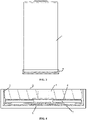
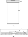
FIG. 6 is a front view of a cylindrical battery according to an embodiment of the present application. -
FIG. 7 is a sectional view of a part B inFIG. 6 . -
FIG. 8 is a top view of a case according to an embodiment of the present application. - It is to be understood that the embodiments described herein are intended to illustrate rather than limiting the present application.
- In the description of the application, it is to be appreciated that the orientation or position relationship indicated by terms such as "center", "longitudinal", "transverse", "length", "width", "thickness", "over", "below", "front", "back", "left", "right", "vertical", "horizontal", "top", "bottom", "inside", "outside", "clockwise" or "counterclockwise" is based on the orientation or position relationship shown in the drawings, which is only for the convenience of describing the present application and simplifying the description, rather than indicating or implying that the device or element referred to must have a specific orientation, be configured and operated in a specific orientation, so it cannot be understood as a limitation to the present application. Furthermore, the terms "first" and "second" are only used for description purposes and cannot be understood as indicating or implying relative importance or implicitly indicating the number of indicated technical features. Thus, the features defined as "first" and "second" can explicitly or implicitly include one or more of the described features. In the description of the present application, "multiple" means two or more, unless otherwise specifically defined.
- In the description of the present application, it is to be noted that, unless otherwise expressly specified and limited, the terms "mounting", "connected to each other", "connected" are to be construed in a broad sense, for example, as permanently connected or detachably connected or integrally connected; mechanically connected; directly connected to each other or indirectly connected to each other via an intermediary; or internally connection of two components or interaction relationship between two components. For those of ordinary skill in the art, specific meanings of the preceding terms in the present application may be construed based on specific situations.
- In the present application, unless otherwise expressly specified and limited, when a first feature is described as "above" or "below" a second feature, the first feature and the second feature may be in direct contact, or be in contact via another feature between the two features. Moreover, when the first feature is described as "on", "above" or "over" the second feature, the first feature is right on, above or over the second feature or the first feature is obliquely on, above or over the second feature, or the first feature is simply at a higher level than the second feature. When the first feature is described as "under", "below" or "underneath" the second feature, the first feature is right under, below or underneath the second feature or the first feature is obliquely under, below or underneath the second feature, or the first feature is simply at a lower level than the second feature.
- As shown in
FIG. 1 to FIG. 4 , a battery with a novel structure according to an embodiment of the present application includes acase 2 and a cap plate 1, specifically, thecase 2 is a cylindrical groove structure, awinding core 3 and a negativecurrent collector 4 are arranged in thecase 2, and an annular bottom end face of thecase 2 is connected to a top end face, facing towards the case, of the cap plate 1 by laser welding. The cap plate 1 has a diameter equal to a maximum diameter of thecase 2. - The top end face, facing towards the
case 2, of the cap plate 1 is provided with anannular protrusion 11, and theannular protrusion 11 has a central axis coinciding with the central axis of the cap plate 1. An edge of the top end face, facing towards thecase 2, of the cap plate 1 is provided with a firstwelding platform face 12, the firstwelding platform face 12 is arranged circumferentially around theannular protrusion 11, and an outer sidewall of theannular protrusion 11 and the firstwelding platform face 12 constitute a stepped face. When the cap plate 1 and thecase 2 need to be connected, theannular protrusion 11 enters the interior of thecase 2 via the annular bottom end face of thecase 2, and an outer sidewall of theannular protrusion 11 comes into contact with an inner sidewall of thecase 2. - When the cap plate 1 is connected to the
case 2, the annular bottom end face of thecase 2 is in contact with the firstwelding platform face 12 and is connected to the firstwelding platform face 12 by laser welding, so that the structure is firm and has a good hermetic performance. - A top end face of the
annular protrusion 11 is provided with a secondwelding platform face 13, and an end face, remote from the cap plate 1, of the negativecurrent collector 4 is connected to a negative electrode of the windingcore 3. Four supporting blocks 5 are arranged between an end face, close to the cap plate 1, of thecurrent collector 4 and the secondwelding platform face 13 of theannular protrusion 11, the four supporting blocks 5 are circumferentially distributed uniformly about the central axis of the cap plate 1, the supporting blocks 5 are made of a conductive material, and ends, remote from the negativecurrent collector 4, of the supporting blocks 5 are connected to the secondwelding platform face 13 by welding. - Ends, remote from the cap plate 1, of the support blocks 5 are arranged integrally with the negative
current collector 4. - The ends, remote from the cap plate 1, of the support blocks 5 are connected to the negative
current collector 4 by welding. - The multiple technical features of the embodiments described above may be combined arbitrarily. For the sake of brevity, not all possible combinations of the multiple technical features of the embodiment described above are described. However, the combinations of these technical features should be considered to be within the scope of the present description as long as no contradictions exist in their combinations.
- For the battery case in the related art, groove-rolling will be performed such that the negative current collector inside the case can be engaged and fixed. However, no groove-rolling process is needed for the case of the battery according to the present application, and for fixing the negative current collector, the top end face of the annular protrusion is provided with the second welding platform face. The end face, remote from the cap plate, of the negative current collector is connected to the negative electrode of the winding core, and the multiple supporting blocks are provided between the end face, close to the cap plate, of the negative current collector and the second welding platform face of the annular protrusion. The supporting blocks are made of a conductive material, the ends, remote from the negative current collector, of the supporting blocks are connected to the second welding platform face by welding, and another ends of the supporting blocks may be arranged integrally with the negative current collector or may be connected to the negative current collector by welding. The cap plate is rigidly connected to the negative current collector through the supporting blocks. A positive current collector, the winding core and the negative current collector arranged in a stacked manner are clamped between a groove bottom face of the case and the supporting blocks.
- In an embodiment, when the cap plate and the case are in a connected state, the outer sidewall of the annular protrusion is in contact with the inner sidewall of the case, so that the annular protrusion can have functions of positioning and connection.
- The present application provides a battery with a novel structure, the battery has high connecting strength between the cap plate and the case and good hermetic performance, and the case does not need to be subjected to the groove-rolling process resulted in internal space loss of the case, so that the utilization rate of the space inside the case is high, and the utilization rate of the space inside the case can be further improved by reducing the height of the supporting blocks. In another aspect, the negative current collector functions as both a sealing terminal, for sealing the opening of the tank, and a negative conductive terminal.
- In an embodiment, the outer sidewall of the annular protrusion is connected to the inner sidewall of the case by laser welding.
- In an embodiment, the battery further includes a winding core and a negative current collector, and the winding core and the negative current collector are located inside the case.
- As shown in
FIG. 5 , in an embodiment, the cap plate includes acurrent collecting region 14 and awelding region 15, thecurrent collecting region 14 is arranged to collect current of the winding core, and thewelding region 15 is configured to be connected to the cap plate by welding. Thecurrent collecting region 14 is an annular protrusion region provided on the top end face, facing towards the case, of the cap plate, and thecurrent collecting region 14 has a central axis coinciding with the central axis of the cap plate, and is arranged to be electrically connected to the negative collector current of the case inside. Thewelding region 15 is another annular protrusion region provided on the top end face, facing towards the case, of the cap plate, and thewelding region 15 has a central axis also coinciding with the central axis of the cap plate, and is configured for welding the battery to seal the battery. - In an embodiment, the negative current collector is a planar structure or a stereoscopic structure, for example, a circular planar structure or an irregular stereoscopic structure, and the negative current collector is configured to collect current of the winding core and achieve electrical connection to the cap plate.
- In an embodiment, the height of the annular protrusion ranges from 0.1mm to 3mm.
- In an embodiment, the annular protrusion has a diameter smaller than an inner diameter of the case by 0.05mm to 0.2mm. There is an assembling relationship between the annular protrusion and the case, such an arrangement facilitates the assembling and flowing of the melted substance in welding. An inclination face, in contact with the case, of the annular protrusion may have an inclination angle ranging from 1° to 5°.
- In an embodiment, 1 < (Height of the annular protrusion)/(Thickness of the cap plate) < 2.
- In an embodiment, the case includes a cylindrical barrel and a groove structure located at the top of the case, and the groove structure is annular-shaped.
- As shown in
FIG. 6 to FIG. 8 , in an embodiment, the battery further includes apositive terminal 6 and aninsulation sealing member 8, the top of the case is provided with a throughhole 21, the throughhole 21 is configured for mounting thepositive terminal 6 and theinsulation sealing member 8, and the throughhole 21 has a central axis coinciding with the central axis of the cap plate. Thus, the central region of the top of the case is thepositive terminal 6, and thepositive terminal 6 and the negative region are located at a same side of the top of the case. - In an embodiment, the battery further includes a positive
current collector 7, the positivecurrent collector 7 is electrically connected to thepositive terminal 6, and the negative current collector is electrically connected to the cap plate. The annular bottom end face of the case is fitted with a peripheral region of the annular protrusion of the cap plate, and the cap plate is connected to the case in a sealed manner by laser welding, thus, the assembly of the battery is completed. - In an embodiment, the height of the battery ranges from 80mm to 130mm and the height of a protruding portion of the
positive terminal 6 ranges from 1mm to 3mm. - In an embodiment, the diameter of the battery may be 46mm.
| 1. cap plate; | 11. annular protrusion; |
| 12. first welding platform face; | 13. second welding platform face; |
| 14. current collecting region; | 15. welding region; |
| 2. case; | 21. through hole; |
| 3. winding core; | 4. negative current collector; |
| 5. supporting block; | 6. positive terminal. |
| 7. positive current collector; and | 8. insulation sealing member. |
Claims (15)
- A battery, comprising a case and a cap plate, wherein the case is a cylindrical groove structure, a top end face, facing towards the case, of the cap plate is provided with an annular protrusion, the annular protrusion has a central axis coinciding with the central axis of the cap plate, an edge of the top end face of the cap plate is provided with a first welding platform face, the first welding platform face is arranged circumferentially around the annular protrusion, an outer sidewall of the annular protrusion and the first welding platform face constitute a stepped face, the annular protrusion enters the interior of the case via an annular bottom end face of the case, and the annular bottom end face of the case is in contact with the first welding platform face and connected to the first welding platform face by laser welding.
- The battery according to claim 1, wherein the outer sidewall of the annular protrusion is in contact with an inner sidewall of the case.
- The battery according to claim 2, wherein the outer sidewall of the annular protrusion is connected to the inner sidewall of the case by laser welding.
- The battery according to claim 1, wherein a top end face of the annular protrusion is provided with a second welding platform face;the battery further comprises a winding core and a negative current collector, and the winding core and the negative current collector are located inside the case; andan end face, remote from the cap plate, of the negative current collector is connected to a negative electrode of the winding core, supporting blocks are arranged between an end face, close to the cap plate, of the current collector and the second welding platform face, and ends, remote from the negative current collector, of the supporting blocks are connected to the second welding platform face by welding.
- The battery according to claim 4, wherein ends, remote from the cap plate, of the supporting blocks are arranged integrally with the negative current collector.
- The battery according to claim 4, wherein the ends, remote from the cap plate, of the supporting blocks are connected to the negative current collector by welding.
- The battery according to claim 4, wherein the cap plate comprises a current collecting region and a welding region, the current collecting region is arranged to collect current of the winding core, and the welding region is arranged to be connected to the cap plate by welding.
- The battery according to claim 7, wherein the negative current collector is a planar structure or a stereoscopic structure.
- The battery according to claim 1, wherein the annular protrusion has a height ranging from 0.1mm to 3mm.
- The battery according to claim 1, wherein the annular protrusion has a diameter smaller than an inner diameter of the case by 0.05mm to 0.2mm.
- The battery according to claim 1, wherein 1 < (Height of the annular protrusion)/(Thickness of the cap plate) < 2 .
- The battery according to claim 1, wherein the case comprises a cylindrical barrel and a groove structure located at a top of the case, and the groove structure is annular-shaped.
- The battery according to claim 4, further comprising a positive terminal and an insulation sealing member, wherein the top of the case is provided with a through hole, the through hole is configured for mounting the positive terminal and the insulation sealing member, and the through hole has a central axis coinciding with the central axis of the cap plate.
- The battery according to claim 13, further comprising a positive current collector, wherein the positive current collector is electrically connected to the positive terminal, and the negative current collector is electrically connected to the cap plate.
- The battery according to claim 12, wherein the battery has a height ranging from 80mm to 130mm and a protruding portion of the positive terminal has a height ranging from 1mm to 3mm.
Priority Applications (1)
| Application Number | Priority Date | Filing Date | Title |
|---|---|---|---|
| HUU2500012U HU6043U (en) | 2021-05-21 | 2022-05-20 | Battery |
Applications Claiming Priority (2)
| Application Number | Priority Date | Filing Date | Title |
|---|---|---|---|
| CN202121100856.8U CN215578775U (en) | 2021-05-21 | 2021-05-21 | Cylindrical battery with novel structure |
| PCT/CN2022/094102 WO2022242744A1 (en) | 2021-05-21 | 2022-05-20 | Battery |
Publications (2)
| Publication Number | Publication Date |
|---|---|
| EP4152492A1 true EP4152492A1 (en) | 2023-03-22 |
| EP4152492A4 EP4152492A4 (en) | 2025-01-29 |
Family
ID=79862838
Family Applications (1)
| Application Number | Title | Priority Date | Filing Date |
|---|---|---|---|
| EP22804063.0A Pending EP4152492A4 (en) | 2021-05-21 | 2022-05-20 | BATTERY |
Country Status (6)
| Country | Link |
|---|---|
| US (1) | US12548829B2 (en) |
| EP (1) | EP4152492A4 (en) |
| CN (1) | CN215578775U (en) |
| DE (1) | DE202022003048U1 (en) |
| HU (1) | HU6043U (en) |
| WO (1) | WO2022242744A1 (en) |
Cited By (2)
| Publication number | Priority date | Publication date | Assignee | Title |
|---|---|---|---|---|
| EP4293769A4 (en) * | 2021-08-23 | 2025-04-30 | Contemporary Amperex Technology (Hong Kong) Limited | BATTERY CELL, BATTERY AND ELECTRICAL DEVICE |
| US12597682B2 (en) | 2021-08-23 | 2026-04-07 | Contemporary Amperex Technology (Hong Kong) Limited | Battery cell, battery, and electric apparatus |
Families Citing this family (11)
| Publication number | Priority date | Publication date | Assignee | Title |
|---|---|---|---|---|
| CN215578776U (en) | 2021-05-21 | 2022-01-18 | 湖北亿纬动力有限公司 | Cylindrical lithium ion battery with novel structure |
| CN215578775U (en) * | 2021-05-21 | 2022-01-18 | 湖北亿纬动力有限公司 | Cylindrical battery with novel structure |
| CN114914596A (en) * | 2022-06-15 | 2022-08-16 | 肇庆小鹏汽车有限公司 | Battery case and battery having the same |
| CN217788479U (en) * | 2022-06-17 | 2022-11-11 | 湖北亿纬动力有限公司 | Cell and battery module with sealed rolling groove |
| US12562442B2 (en) * | 2022-09-09 | 2026-02-24 | Eve Power Co., Ltd. | Lid plate and battery |
| CN116207412A (en) * | 2023-01-31 | 2023-06-02 | 湖北亿纬动力有限公司 | Battery, battery module and electric equipment |
| HU6091U (en) * | 2023-01-31 | 2026-05-28 | Eve Power Co., Ltd. | Battery |
| CN220368098U (en) * | 2023-02-23 | 2024-01-19 | 蜂巢能源科技股份有限公司 | Battery cell |
| CN116454525A (en) * | 2023-04-27 | 2023-07-18 | 湖北亿纬动力有限公司 | Battery cover plate, battery shell and battery |
| CN117393934B (en) * | 2023-10-24 | 2024-12-17 | 东莞市创明电池技术有限公司 | Cylindrical battery and method for assembling the same |
| SE546984C2 (en) * | 2024-03-20 | 2025-03-25 | Northvolt Ab | Lid closure for a secondary cell |
Family Cites Families (14)
| Publication number | Priority date | Publication date | Assignee | Title |
|---|---|---|---|---|
| JPH1040921A (en) * | 1996-07-26 | 1998-02-13 | Fuji Photo Film Co Ltd | Non-aqueous secondary battery |
| JP3709197B2 (en) * | 2003-08-25 | 2005-10-19 | 松下電器産業株式会社 | Cylindrical battery and manufacturing method thereof |
| KR100973423B1 (en) * | 2006-10-16 | 2010-08-02 | 주식회사 엘지화학 | Cylindrical battery with improved safety |
| US8057928B2 (en) * | 2009-06-12 | 2011-11-15 | Tesla Motors, Inc. | Cell cap assembly with recessed terminal and enlarged insulating gasket |
| CN208507853U (en) | 2018-08-31 | 2019-02-15 | 成都市银隆新能源产业技术研究有限公司 | A kind of lithium battery |
| CN109904380A (en) | 2019-03-26 | 2019-06-18 | 阮孟雪 | A kind of circle high power lithium ion cell structure and preparation method thereof |
| CN110880563B (en) | 2019-10-10 | 2021-12-14 | 宁德新能源科技有限公司 | Battery case assembly and battery having the same |
| CN210668432U (en) * | 2019-10-10 | 2020-06-02 | 宁德新能源科技有限公司 | Shell and battery with same |
| CN112151732A (en) * | 2020-09-30 | 2020-12-29 | 星恒电源(滁州)有限公司 | Round lithium battery and preparation method thereof |
| CN112290168B (en) | 2020-10-16 | 2022-11-08 | 武汉逸飞激光股份有限公司 | Full-tab lithium battery and preparation method thereof |
| CN216354464U (en) | 2021-04-30 | 2022-04-19 | 蜂巢能源科技(无锡)有限公司 | Battery cover plate assembly and lithium battery |
| CN113346201A (en) * | 2021-05-21 | 2021-09-03 | 湖北亿纬动力有限公司 | Cylindrical battery, battery module and battery pack |
| CN215578775U (en) | 2021-05-21 | 2022-01-18 | 湖北亿纬动力有限公司 | Cylindrical battery with novel structure |
| CN216213942U (en) | 2021-09-30 | 2022-04-05 | 宁德时代新能源科技股份有限公司 | Battery cell, battery and power consumption device |
-
2021
- 2021-05-21 CN CN202121100856.8U patent/CN215578775U/en active Active
-
2022
- 2022-05-20 DE DE202022003048.7U patent/DE202022003048U1/en active Active
- 2022-05-20 WO PCT/CN2022/094102 patent/WO2022242744A1/en not_active Ceased
- 2022-05-20 US US18/013,939 patent/US12548829B2/en active Active
- 2022-05-20 HU HUU2500012U patent/HU6043U/en unknown
- 2022-05-20 EP EP22804063.0A patent/EP4152492A4/en active Pending
Cited By (3)
| Publication number | Priority date | Publication date | Assignee | Title |
|---|---|---|---|---|
| EP4293769A4 (en) * | 2021-08-23 | 2025-04-30 | Contemporary Amperex Technology (Hong Kong) Limited | BATTERY CELL, BATTERY AND ELECTRICAL DEVICE |
| US12597682B2 (en) | 2021-08-23 | 2026-04-07 | Contemporary Amperex Technology (Hong Kong) Limited | Battery cell, battery, and electric apparatus |
| EP4718622A3 (en) * | 2021-08-23 | 2026-06-03 | Contemporary Amperex Technology (Hong Kong) Limited | Battery cell, battery, and electrical apparatus |
Also Published As
| Publication number | Publication date |
|---|---|
| EP4152492A4 (en) | 2025-01-29 |
| US20240072343A1 (en) | 2024-02-29 |
| US12548829B2 (en) | 2026-02-10 |
| WO2022242744A1 (en) | 2022-11-24 |
| DE202022003048U1 (en) | 2024-08-29 |
| HU6043U (en) | 2026-03-28 |
| CN215578775U (en) | 2022-01-18 |
Similar Documents
| Publication | Publication Date | Title |
|---|---|---|
| US12548829B2 (en) | Battery | |
| US12183957B2 (en) | Assembled structure of pole and pole current collector disk, and battery | |
| EP4148881A1 (en) | Cylindrical lithium-ion battery | |
| EP3790072B1 (en) | Secondary battery top cover assembly and secondary battery | |
| CN115066805B (en) | Battery cell, battery, electric device, manufacturing method and system of battery cell | |
| JP4987563B2 (en) | Interconnector and series connection battery | |
| EP2228852A1 (en) | Rechargeable battery comprising current collecting plates with improved structure | |
| US20240195029A1 (en) | Power battery cover and power battery | |
| US12119503B2 (en) | Cap assembly and secondary battery | |
| CN115395145A (en) | A cylindrical battery | |
| CN217691568U (en) | Pole column assembly, battery cover plate, battery and battery device | |
| CN217239703U (en) | High energy density cylinder type battery | |
| CN114639926A (en) | Battery and method for assembling battery | |
| US12100550B2 (en) | Electrochemical energy storage device | |
| CN221574074U (en) | Battery and battery device | |
| CN221596606U (en) | Battery cell | |
| CN220382285U (en) | Poles, top cover components, battery cells, batteries and electrical devices | |
| CN219067160U (en) | Battery cell | |
| CN118676550A (en) | Pole mounting structure and battery | |
| CN216928724U (en) | Button cell | |
| CN117480675A (en) | Batteries and electrical equipment | |
| CN221828095U (en) | A battery assembly structure | |
| CN223309094U (en) | Cover assembly, single cell, battery module and battery pack | |
| JPS63143755A (en) | Electrochemical battery including container support | |
| JPS63143754A (en) | Electrochemical cell with combined negative electrode |
Legal Events
| Date | Code | Title | Description |
|---|---|---|---|
| STAA | Information on the status of an ep patent application or granted ep patent |
Free format text: STATUS: THE INTERNATIONAL PUBLICATION HAS BEEN MADE |
|
| PUAI | Public reference made under article 153(3) epc to a published international application that has entered the european phase |
Free format text: ORIGINAL CODE: 0009012 |
|
| STAA | Information on the status of an ep patent application or granted ep patent |
Free format text: STATUS: REQUEST FOR EXAMINATION WAS MADE |
|
| 17P | Request for examination filed |
Effective date: 20221214 |
|
| AK | Designated contracting states |
Kind code of ref document: A1 Designated state(s): AL AT BE BG CH CY CZ DE DK EE ES FI FR GB GR HR HU IE IS IT LI LT LU LV MC MK MT NL NO PL PT RO RS SE SI SK SM TR |
|
| DAV | Request for validation of the european patent (deleted) | ||
| DAX | Request for extension of the european patent (deleted) | ||
| A4 | Supplementary search report drawn up and despatched |
Effective date: 20250103 |
|
| RIC1 | Information provided on ipc code assigned before grant |
Ipc: H01M 50/566 20210101ALI20241220BHEP Ipc: H01M 50/559 20210101ALI20241220BHEP Ipc: H01M 50/107 20210101ALI20241220BHEP Ipc: H01M 50/545 20210101ALI20241220BHEP Ipc: H01M 50/152 20210101ALI20241220BHEP Ipc: H01M 50/169 20210101AFI20241220BHEP |