EP4152484A1 - Battery box body, battery set, and battery box - Google Patents
Battery box body, battery set, and battery box Download PDFInfo
- Publication number
- EP4152484A1 EP4152484A1 EP20936668.1A EP20936668A EP4152484A1 EP 4152484 A1 EP4152484 A1 EP 4152484A1 EP 20936668 A EP20936668 A EP 20936668A EP 4152484 A1 EP4152484 A1 EP 4152484A1
- Authority
- EP
- European Patent Office
- Prior art keywords
- housing
- fixing bracket
- battery box
- box body
- disposed
- Prior art date
- Legal status (The legal status is an assumption and is not a legal conclusion. Google has not performed a legal analysis and makes no representation as to the accuracy of the status listed.)
- Granted
Links
Images


Classifications
-
- H—ELECTRICITY
- H01—ELECTRIC ELEMENTS
- H01M—PROCESSES OR MEANS, e.g. BATTERIES, FOR THE DIRECT CONVERSION OF CHEMICAL ENERGY INTO ELECTRICAL ENERGY
- H01M50/00—Constructional details or processes of manufacture of the non-active parts of electrochemical cells other than fuel cells, e.g. hybrid cells
- H01M50/20—Mountings; Secondary casings or frames; Racks, modules or packs; Suspension devices; Shock absorbers; Transport or carrying devices; Holders
- H01M50/204—Racks, modules or packs for multiple batteries or multiple cells
-
- H—ELECTRICITY
- H01—ELECTRIC ELEMENTS
- H01M—PROCESSES OR MEANS, e.g. BATTERIES, FOR THE DIRECT CONVERSION OF CHEMICAL ENERGY INTO ELECTRICAL ENERGY
- H01M10/00—Secondary cells; Manufacture thereof
- H01M10/42—Methods or arrangements for servicing or maintenance of secondary cells or secondary half-cells
- H01M10/4207—Methods or arrangements for servicing or maintenance of secondary cells or secondary half-cells for several batteries or cells simultaneously or sequentially
-
- H—ELECTRICITY
- H01—ELECTRIC ELEMENTS
- H01M—PROCESSES OR MEANS, e.g. BATTERIES, FOR THE DIRECT CONVERSION OF CHEMICAL ENERGY INTO ELECTRICAL ENERGY
- H01M10/00—Secondary cells; Manufacture thereof
- H01M10/42—Methods or arrangements for servicing or maintenance of secondary cells or secondary half-cells
- H01M10/425—Structural combination with electronic components, e.g. electronic circuits integrated to the outside of the casing
-
- H—ELECTRICITY
- H01—ELECTRIC ELEMENTS
- H01M—PROCESSES OR MEANS, e.g. BATTERIES, FOR THE DIRECT CONVERSION OF CHEMICAL ENERGY INTO ELECTRICAL ENERGY
- H01M10/00—Secondary cells; Manufacture thereof
- H01M10/42—Methods or arrangements for servicing or maintenance of secondary cells or secondary half-cells
- H01M10/48—Accumulators combined with arrangements for measuring, testing or indicating the condition of cells, e.g. the level or density of the electrolyte
- H01M10/482—Accumulators combined with arrangements for measuring, testing or indicating the condition of cells, e.g. the level or density of the electrolyte for several batteries or cells simultaneously or sequentially
-
- H—ELECTRICITY
- H01—ELECTRIC ELEMENTS
- H01M—PROCESSES OR MEANS, e.g. BATTERIES, FOR THE DIRECT CONVERSION OF CHEMICAL ENERGY INTO ELECTRICAL ENERGY
- H01M10/00—Secondary cells; Manufacture thereof
- H01M10/42—Methods or arrangements for servicing or maintenance of secondary cells or secondary half-cells
- H01M10/48—Accumulators combined with arrangements for measuring, testing or indicating the condition of cells, e.g. the level or density of the electrolyte
- H01M10/486—Accumulators combined with arrangements for measuring, testing or indicating the condition of cells, e.g. the level or density of the electrolyte for measuring temperature
-
- H—ELECTRICITY
- H01—ELECTRIC ELEMENTS
- H01M—PROCESSES OR MEANS, e.g. BATTERIES, FOR THE DIRECT CONVERSION OF CHEMICAL ENERGY INTO ELECTRICAL ENERGY
- H01M10/00—Secondary cells; Manufacture thereof
- H01M10/60—Heating or cooling; Temperature control
- H01M10/61—Types of temperature control
- H01M10/613—Cooling or keeping cold
-
- H—ELECTRICITY
- H01—ELECTRIC ELEMENTS
- H01M—PROCESSES OR MEANS, e.g. BATTERIES, FOR THE DIRECT CONVERSION OF CHEMICAL ENERGY INTO ELECTRICAL ENERGY
- H01M10/00—Secondary cells; Manufacture thereof
- H01M10/60—Heating or cooling; Temperature control
- H01M10/62—Heating or cooling; Temperature control specially adapted for specific applications
- H01M10/625—Vehicles
-
- H—ELECTRICITY
- H01—ELECTRIC ELEMENTS
- H01M—PROCESSES OR MEANS, e.g. BATTERIES, FOR THE DIRECT CONVERSION OF CHEMICAL ENERGY INTO ELECTRICAL ENERGY
- H01M10/00—Secondary cells; Manufacture thereof
- H01M10/60—Heating or cooling; Temperature control
- H01M10/64—Heating or cooling; Temperature control characterised by the shape of the cells
- H01M10/647—Prismatic or flat cells, e.g. pouch cells
-
- H—ELECTRICITY
- H01—ELECTRIC ELEMENTS
- H01M—PROCESSES OR MEANS, e.g. BATTERIES, FOR THE DIRECT CONVERSION OF CHEMICAL ENERGY INTO ELECTRICAL ENERGY
- H01M10/00—Secondary cells; Manufacture thereof
- H01M10/60—Heating or cooling; Temperature control
- H01M10/65—Means for temperature control structurally associated with the cells
- H01M10/655—Solid structures for heat exchange or heat conduction
- H01M10/6551—Surfaces specially adapted for heat dissipation or radiation, e.g. fins or coatings
-
- H—ELECTRICITY
- H01—ELECTRIC ELEMENTS
- H01M—PROCESSES OR MEANS, e.g. BATTERIES, FOR THE DIRECT CONVERSION OF CHEMICAL ENERGY INTO ELECTRICAL ENERGY
- H01M10/00—Secondary cells; Manufacture thereof
- H01M10/60—Heating or cooling; Temperature control
- H01M10/65—Means for temperature control structurally associated with the cells
- H01M10/655—Solid structures for heat exchange or heat conduction
- H01M10/6554—Rods or plates
-
- H—ELECTRICITY
- H01—ELECTRIC ELEMENTS
- H01M—PROCESSES OR MEANS, e.g. BATTERIES, FOR THE DIRECT CONVERSION OF CHEMICAL ENERGY INTO ELECTRICAL ENERGY
- H01M10/00—Secondary cells; Manufacture thereof
- H01M10/60—Heating or cooling; Temperature control
- H01M10/65—Means for temperature control structurally associated with the cells
- H01M10/655—Solid structures for heat exchange or heat conduction
- H01M10/6556—Solid parts with flow channel passages or pipes for heat exchange
-
- H—ELECTRICITY
- H01—ELECTRIC ELEMENTS
- H01M—PROCESSES OR MEANS, e.g. BATTERIES, FOR THE DIRECT CONVERSION OF CHEMICAL ENERGY INTO ELECTRICAL ENERGY
- H01M50/00—Constructional details or processes of manufacture of the non-active parts of electrochemical cells other than fuel cells, e.g. hybrid cells
- H01M50/20—Mountings; Secondary casings or frames; Racks, modules or packs; Suspension devices; Shock absorbers; Transport or carrying devices; Holders
- H01M50/204—Racks, modules or packs for multiple batteries or multiple cells
- H01M50/207—Racks, modules or packs for multiple batteries or multiple cells characterised by their shape
- H01M50/209—Racks, modules or packs for multiple batteries or multiple cells characterised by their shape adapted for prismatic or rectangular cells
-
- H—ELECTRICITY
- H01—ELECTRIC ELEMENTS
- H01M—PROCESSES OR MEANS, e.g. BATTERIES, FOR THE DIRECT CONVERSION OF CHEMICAL ENERGY INTO ELECTRICAL ENERGY
- H01M50/00—Constructional details or processes of manufacture of the non-active parts of electrochemical cells other than fuel cells, e.g. hybrid cells
- H01M50/20—Mountings; Secondary casings or frames; Racks, modules or packs; Suspension devices; Shock absorbers; Transport or carrying devices; Holders
- H01M50/204—Racks, modules or packs for multiple batteries or multiple cells
- H01M50/207—Racks, modules or packs for multiple batteries or multiple cells characterised by their shape
- H01M50/211—Racks, modules or packs for multiple batteries or multiple cells characterised by their shape adapted for pouch cells
-
- H—ELECTRICITY
- H01—ELECTRIC ELEMENTS
- H01M—PROCESSES OR MEANS, e.g. BATTERIES, FOR THE DIRECT CONVERSION OF CHEMICAL ENERGY INTO ELECTRICAL ENERGY
- H01M50/00—Constructional details or processes of manufacture of the non-active parts of electrochemical cells other than fuel cells, e.g. hybrid cells
- H01M50/20—Mountings; Secondary casings or frames; Racks, modules or packs; Suspension devices; Shock absorbers; Transport or carrying devices; Holders
- H01M50/218—Mountings; Secondary casings or frames; Racks, modules or packs; Suspension devices; Shock absorbers; Transport or carrying devices; Holders characterised by the material
- H01M50/22—Mountings; Secondary casings or frames; Racks, modules or packs; Suspension devices; Shock absorbers; Transport or carrying devices; Holders characterised by the material of the casings or racks
- H01M50/222—Inorganic material
- H01M50/224—Metals
-
- H—ELECTRICITY
- H01—ELECTRIC ELEMENTS
- H01M—PROCESSES OR MEANS, e.g. BATTERIES, FOR THE DIRECT CONVERSION OF CHEMICAL ENERGY INTO ELECTRICAL ENERGY
- H01M50/00—Constructional details or processes of manufacture of the non-active parts of electrochemical cells other than fuel cells, e.g. hybrid cells
- H01M50/20—Mountings; Secondary casings or frames; Racks, modules or packs; Suspension devices; Shock absorbers; Transport or carrying devices; Holders
- H01M50/244—Secondary casings; Racks; Suspension devices; Carrying devices; Holders characterised by their mounting method
-
- H—ELECTRICITY
- H01—ELECTRIC ELEMENTS
- H01M—PROCESSES OR MEANS, e.g. BATTERIES, FOR THE DIRECT CONVERSION OF CHEMICAL ENERGY INTO ELECTRICAL ENERGY
- H01M50/00—Constructional details or processes of manufacture of the non-active parts of electrochemical cells other than fuel cells, e.g. hybrid cells
- H01M50/20—Mountings; Secondary casings or frames; Racks, modules or packs; Suspension devices; Shock absorbers; Transport or carrying devices; Holders
- H01M50/249—Mountings; Secondary casings or frames; Racks, modules or packs; Suspension devices; Shock absorbers; Transport or carrying devices; Holders specially adapted for aircraft or vehicles, e.g. cars or trains
-
- H—ELECTRICITY
- H01—ELECTRIC ELEMENTS
- H01M—PROCESSES OR MEANS, e.g. BATTERIES, FOR THE DIRECT CONVERSION OF CHEMICAL ENERGY INTO ELECTRICAL ENERGY
- H01M50/00—Constructional details or processes of manufacture of the non-active parts of electrochemical cells other than fuel cells, e.g. hybrid cells
- H01M50/20—Mountings; Secondary casings or frames; Racks, modules or packs; Suspension devices; Shock absorbers; Transport or carrying devices; Holders
- H01M50/258—Modular batteries; Casings provided with means for assembling
-
- H—ELECTRICITY
- H01—ELECTRIC ELEMENTS
- H01M—PROCESSES OR MEANS, e.g. BATTERIES, FOR THE DIRECT CONVERSION OF CHEMICAL ENERGY INTO ELECTRICAL ENERGY
- H01M50/00—Constructional details or processes of manufacture of the non-active parts of electrochemical cells other than fuel cells, e.g. hybrid cells
- H01M50/20—Mountings; Secondary casings or frames; Racks, modules or packs; Suspension devices; Shock absorbers; Transport or carrying devices; Holders
- H01M50/262—Mountings; Secondary casings or frames; Racks, modules or packs; Suspension devices; Shock absorbers; Transport or carrying devices; Holders with fastening means, e.g. locks
-
- H—ELECTRICITY
- H01—ELECTRIC ELEMENTS
- H01M—PROCESSES OR MEANS, e.g. BATTERIES, FOR THE DIRECT CONVERSION OF CHEMICAL ENERGY INTO ELECTRICAL ENERGY
- H01M50/00—Constructional details or processes of manufacture of the non-active parts of electrochemical cells other than fuel cells, e.g. hybrid cells
- H01M50/20—Mountings; Secondary casings or frames; Racks, modules or packs; Suspension devices; Shock absorbers; Transport or carrying devices; Holders
- H01M50/271—Lids or covers for the racks or secondary casings
-
- H—ELECTRICITY
- H01—ELECTRIC ELEMENTS
- H01M—PROCESSES OR MEANS, e.g. BATTERIES, FOR THE DIRECT CONVERSION OF CHEMICAL ENERGY INTO ELECTRICAL ENERGY
- H01M50/00—Constructional details or processes of manufacture of the non-active parts of electrochemical cells other than fuel cells, e.g. hybrid cells
- H01M50/20—Mountings; Secondary casings or frames; Racks, modules or packs; Suspension devices; Shock absorbers; Transport or carrying devices; Holders
- H01M50/289—Mountings; Secondary casings or frames; Racks, modules or packs; Suspension devices; Shock absorbers; Transport or carrying devices; Holders characterised by spacing elements or positioning means within frames, racks or packs
- H01M50/291—Mountings; Secondary casings or frames; Racks, modules or packs; Suspension devices; Shock absorbers; Transport or carrying devices; Holders characterised by spacing elements or positioning means within frames, racks or packs characterised by their shape
-
- H—ELECTRICITY
- H01—ELECTRIC ELEMENTS
- H01M—PROCESSES OR MEANS, e.g. BATTERIES, FOR THE DIRECT CONVERSION OF CHEMICAL ENERGY INTO ELECTRICAL ENERGY
- H01M50/00—Constructional details or processes of manufacture of the non-active parts of electrochemical cells other than fuel cells, e.g. hybrid cells
- H01M50/20—Mountings; Secondary casings or frames; Racks, modules or packs; Suspension devices; Shock absorbers; Transport or carrying devices; Holders
- H01M50/298—Mountings; Secondary casings or frames; Racks, modules or packs; Suspension devices; Shock absorbers; Transport or carrying devices; Holders characterised by the wiring of battery packs
-
- H—ELECTRICITY
- H05—ELECTRIC TECHNIQUES NOT OTHERWISE PROVIDED FOR
- H05K—PRINTED CIRCUITS; CASINGS OR CONSTRUCTIONAL DETAILS OF ELECTRIC APPARATUS; MANUFACTURE OF ASSEMBLAGES OF ELECTRICAL COMPONENTS
- H05K7/00—Constructional details common to different types of electric apparatus
- H05K7/20—Modifications to facilitate cooling, ventilating, or heating
- H05K7/2039—Modifications to facilitate cooling, ventilating, or heating characterised by the heat transfer by conduction from the heat generating element to a dissipating body
-
- H—ELECTRICITY
- H01—ELECTRIC ELEMENTS
- H01M—PROCESSES OR MEANS, e.g. BATTERIES, FOR THE DIRECT CONVERSION OF CHEMICAL ENERGY INTO ELECTRICAL ENERGY
- H01M10/00—Secondary cells; Manufacture thereof
- H01M10/42—Methods or arrangements for servicing or maintenance of secondary cells or secondary half-cells
- H01M10/425—Structural combination with electronic components, e.g. electronic circuits integrated to the outside of the casing
- H01M2010/4271—Battery management systems including electronic circuits, e.g. control of current or voltage to keep battery in healthy state, cell balancing
-
- H—ELECTRICITY
- H01—ELECTRIC ELEMENTS
- H01M—PROCESSES OR MEANS, e.g. BATTERIES, FOR THE DIRECT CONVERSION OF CHEMICAL ENERGY INTO ELECTRICAL ENERGY
- H01M2220/00—Batteries for particular applications
- H01M2220/20—Batteries in motive systems, e.g. vehicle, ship, plane
-
- Y—GENERAL TAGGING OF NEW TECHNOLOGICAL DEVELOPMENTS; GENERAL TAGGING OF CROSS-SECTIONAL TECHNOLOGIES SPANNING OVER SEVERAL SECTIONS OF THE IPC; TECHNICAL SUBJECTS COVERED BY FORMER USPC CROSS-REFERENCE ART COLLECTIONS [XRACs] AND DIGESTS
- Y02—TECHNOLOGIES OR APPLICATIONS FOR MITIGATION OR ADAPTATION AGAINST CLIMATE CHANGE
- Y02E—REDUCTION OF GREENHOUSE GAS [GHG] EMISSIONS, RELATED TO ENERGY GENERATION, TRANSMISSION OR DISTRIBUTION
- Y02E60/00—Enabling technologies; Technologies with a potential or indirect contribution to GHG emissions mitigation
- Y02E60/10—Energy storage using batteries
Definitions
- This application relates to the technical field of batteries, and in particular, to a battery box body, a battery pack, and a battery box.
- An electric vehicle is generally powered by electrical energy provided by a battery pack, so as to be driven to move.
- the battery pack generally includes a battery box body and a cell module accommodated in the battery box body.
- the battery box body serves main functions of supporting, fixing, and protecting the cell module, and needs to be of high mechanical strength, high electrical performance, high thermal performance, and high troubleshooting capabilities. Generally, all such factors are criteria for determining whether the battery pack is good or not.
- the battery box body in the prior art is complicated in structure, and is not satisfactory enough in thermal performance.
- a battery box body including: a housing, provided with an accommodation cavity; a partition plate, disposed in the accommodation cavity, and configured to partition the accommodation cavity into a plurality of space blocks, where each space block is configured to receive a cell module; a fixing bracket, detachably disposed on the housing, and configured to fix a battery management system and the cell module to the housing, where two opposite sides of the fixing bracket abut against sidewalls of the housing respectively; and a cover body, detachably disposed on the housing and configured to cap the accommodation cavity.
- the housing includes a plurality of sidewalls, guiding pieces are disposed on two opposite sidewalls respectively, and the fixing bracket is sandwiched between the two guiding pieces.
- a side of the guiding piece opposite from a sidewall on which the guiding piece is located tilts against a plane of the sidewall, and the two guiding pieces are disposed parallel to each other.
- the fixing bracket is connected onto the partition plate and the housing by means of snap-fastening and/or bolting.
- a mounting portion is disposed on the sidewall of the housing, and the fixing bracket is fixed onto the mounting portion by a bolt.
- the cover body is detachably disposed on the partition plate.
- the fixing bracket is provided with a slot.
- the partition plate is provided with a hook, and the hook engages in the slot.
- the partition plate includes a first end and a second end disposed opposite to each other, a gap is formed between the first end and the housing, and the second end is connected to a sidewall of the housing.
- the partition plate is provided with a notch near the second end.
- the notch is configured to receive a wire harness for connecting the battery management system and the cell module.
- both the partition plate and the housing are made of heat-dissipating materials.
- a heat sink is disposed on both an outer side of the housing and an outer side of the cover body.
- the cover body is provided with a pressing block.
- the pressing block presses on the fixing bracket, and a cushion is disposed between the pressing block and the fixing bracket.
- a pressure sensor is disposed on the cushion and is configured to sense pressure exerted by the cover body on the fixing bracket.
- a harness limiting structure is disposed on the fixing bracket, and is configured to limit a position of a wire harness in the battery box body.
- the harness limiting structure includes a limiting block disposed protrusively on the fixing bracket.
- a limiting hole is disposed on the limiting block. The limiting hole is configured to allow a wire harness to pass through the hole.
- a battery pack including the foregoing battery box body, a cell module, and a battery management system.
- the cell module is accommodated in an accommodation cavity.
- a fixing bracket presses on the cell module.
- the battery management system is fixed on the fixing bracket and abuts against a cover body.
- a radiator is disposed on the battery management system. The radiator is bonded to the cover body by a thermally conductive adhesive.
- a pot gel is disposed in the housing.
- the pot gel is configured to equalize a temperature of the cell module.
- a fixing structure is disposed on the fixing bracket, and is configured to limit a position of the battery management system.
- the fixing structure is a protruding post disposed protrusively on the fixing bracket.
- the protruding post is plural in number, and the plurality of protruding posts are disposed around the battery management system.
- a battery box is disclosed, including the foregoing battery pack.
- the battery box body is structurally simple and easy to assemble, and is of high mechanical strength and high heat-dissipation performance.
- first and second used below are merely intended for descriptive purposes but are not to be understood as indicating or implying relative importance or as implicitly specifying the number of technical features indicated. Therefore, a feature qualified by “first”, “second” and the like may explicitly or implicitly include one such feature or a plurality of the features. In the description of this application, unless otherwise specified, "a plurality of” means two or more.
- the directional terms such as “upper”, “lower”, “left”, and “right” are defined relative to the orientation in which a component is schematically placed in the drawings. Understandably, the directional terms are relative concepts that are used for relative description and clarification, and may vary accordingly depending on the orientation of the component in the drawings.
- connection is understood in a broad sense.
- a “connection” may be a fixed connection, a detachable connection, or an integrated whole, and may be a direct connection or an indirect connection implemented through an intermediary.
- connection and/or used herein includes any and all combinations of one or more related items preceding and following the term.
- the battery box body and the battery pack according to some embodiments of this application are applicable to electronic devices, especially electric vehicles and the like.
- FIG. 1 is a schematic structural diagram of a battery box body 1 according to an embodiment of the present application.
- the battery box body 1 includes a housing 10, a partition plate 16, a fixing bracket 12, and a cover body 14.
- the fixing bracket 12 is detachably disposed on the housing 10.
- the cover body 14 presses on the fixing bracket 12.
- the housing 10 is roughly rectangular and is provided with an accommodation cavity 100.
- the housing 10 includes a first sidewall 101, a second sidewall 102, a third sidewall 103, and a fourth sidewall 104, and a bottom plate 105 that is connected to the first sidewall 101, the second sidewall 102, and the first sidewall 103, and the fourth sidewall 104.
- the first sidewall 101, the second sidewall 102, the third sidewall 103, the fourth sidewall 104, and the bottom plate 105 close in to form the accommodation cavity 100.
- the accommodation cavity 100 is configured to accommodate the cell module. In some embodiments, the accommodation cavity 100 can accommodate two or more cell modules.
- the partition plate 16 is disposed in the accommodation cavity 100, and is configured to partition the accommodation cavity 100 into a plurality of space blocks. Each space block may be configured to receive a cell module. In an embodiment shown in the drawing, there is one partition plate 16 that partitions the accommodation cavity 100 into two space blocks. Understandably, the number of partition plates 16 may depend on the number of cell modules that need to be disposed. For example, if there are three cell modules, two partition plates 16 may be disposed for partitioning.
- the partition plate 16 includes a first end 161 and a second end 162.
- the first end 161 is opposite to the second end 162, and the second end 162 abuts against the third sidewall 103 of the housing 10.
- a gap 106 is disposed between the first end 161 and the first sidewall 101.
- the first end 161 is also provided with a notch 163.
- the gap 160 and the notch 163 are configured to facilitate passage of a wire harness between the space blocks.
- the housing 10 is provided with a first mounting portion 107.
- the first mounting portion 107 is configured to mount and fix the fixing bracket 12.
- the first mounting portion 107 is a positioning hole.
- the fixing bracket 12 coordinates with the positioning hole through a bolt, so that the fixing bracket 12 is fastened onto the housing 10.
- the fixing bracket 12 is configured to fix a battery management system (Battery Management System, BMS) and a cell module.
- the fixing bracket 12 includes a first side 120 and a second side 121 that is opposite to the first side 120.
- the first side 120 abuts against the second side 121 on the second sidewall 102 and on the fourth sidewall 104 of the housing 10 separately.
- the fixing bracket 12 is provided with a second mounting portion 122 corresponding to the first mounting portion 107.
- the second mounting portion 122 is a via hole corresponding to the positioning hole. A bolt passes through the via hole and the positioning hole consecutively to fasten the fixing bracket 12 to the housing 10.
- the means of fastening between the fixing bracket 12 and the housing 10 is not limited to the positioning hole and the via hole shown in the drawing, but may be another similar fastening structure as long as the fastening structure can fasten the fixing bracket 12 onto the housing 10.
- the fastening structure may be a buckle structure.
- Either the fixing bracket 12 or the housing 10 is provided with a slot, and the other is provided with a hook. The hook engages with the slot to serve a fastening function.
- the fixing bracket 12 may also be fastened to the partition plate 16.
- the partition plate 16 is provided with a hook 164
- the fixing bracket 12 is provided with a slot 123 correspondingly.
- the hook 164 engages with the slot 123 to fasten the fixing bracket 12 to the partition plate 16.
- the means of fastening the fixing bracket 12 to the partition plate 16 is not limited to an embodiment shown in the drawing, but may be any other appropriate fastening means as long as the fastening means can fasten the fixing bracket 12 to the partition plate 16.
- the housing 10 is provided with guiding pieces 109.
- the fixing bracket 12 is sandwiched between two guiding pieces 109.
- the guiding pieces 109 are guiding blocks disposed on the second sidewall 102 and the fourth sidewall 104.
- Each of the guiding blocks is a bevel structure.
- a side of the guiding block opposite from the second sidewall 102 or the fourth sidewall 104 tilts against a plane on which the second sidewall 102 or the fourth sidewall 104 is located.
- the guiding piece 109 disposed on the second sidewall 102 is approximately parallel to the guiding piece disposed on the fourth sidewall 104.
- the guiding piece 109 may be other structures as long as the structure facilitates mounting of the fixing bracket 12 onto the housing 10.
- the first side 120 and the second side 121 of the fixing bracket 12 may be provided with guiding strips.
- the second sidewall 102 and the fourth sidewall 104 may be provided with guiding slots correspondingly. The guiding strips coordinate with the guiding slots so that the fixing bracket 12 is guided to be assembled onto the housing 10.
- the fixing bracket 12 is configured to carry the battery management system.
- the fixing bracket 12 is provided with a fixing structure 124 configured to limit the position of the battery management system when the battery management system is carried on the fixing bracket 12, so that the position of the battery management system remains unchanged relative to the fixing bracket 12.
- the fixing structure 124 is four protruding posts disposed protrusively on the fixing bracket 12 and configured to limit horizontal displacement and vertical displacement of the battery management system respectively.
- the limiting structure may be another structure that fits with the shape of the battery management system, such as a limiting slot, a limiting buckle, or the like.
- the fixing bracket 12 is further provided with a harness limiting structure 125.
- the harness limiting structure 125 is configured to limit the position of a wire harness that passes through the structure.
- the harness limiting structure 125 is a limiting block that is disposed protrusively on a main body of the fixing bracket 12.
- the limiting block is provided with a limiting hole to allow the wire harness or a cable tie to pass through the limiting hole, thereby limiting the position of the wire harness or the cable tie.
- the cover body 14 detachably presses on the housing 10 to cap the accommodation cavity 100.
- An accommodation space enclosed between the cover body 14 and the partition plate 16 is configured to allow for assembling of the battery management system.
- An accommodation space enclosed between the partition plate 16 and the housing 10 is configured to receive the cell module.
- the housing 10 is provided with a third mounting portion 108.
- the cover body 14 is provided with a fourth mounting portion 140 correspondingly.
- the third mounting portion 108 coordinates with the fourth mounting portion 140 to fix the cover body 14 onto the housing 10.
- the third mounting portion 108 is a screw hole
- the fourth mounting portion is a via hole.
- the bolt passes through the via hole and the screw hole to fasten the cover body 14 to the housing 10.
- the means of fastening the housing 10 to the cover body 14 is not limited to some embodiment shown in the drawing, but may be any other appropriate fastening structure as long as the fastening structure can fasten the cover body 14 to the housing 10.
- the fourth mounting portion 140 is a screw hole
- the housing 10 is a via hole.
- the cover body 14 is provided with a pressing block 141.
- the pressing block 141 presses on the fixing bracket 12, so that the fixing bracket 12 is further fastened between the cover body 14 and the housing 10.
- the pressing block 141 is disposed at two opposite sides of the cover body 14 separately and includes a plurality of pressing plates that are spaced apart. Understandably, in other embodiments, the shape of the pressing block 141 is not limited to some embodiment shown in the drawing. For example, there may be an integrated pressing block or several pressing blocks spaced apart, and the shape of the pressing block may be any appropriate geometric shapes such as a square or trapezoid.
- a cushion 13 is disposed between the pressing block 141 and the fixing bracket 12.
- the cushion 13 is configured to buffer the pressure exerted by the cover body 14 on the fixing bracket 12.
- the cushion 13 is a flexible rubber pad. Understandably, in other embodiments, the cushion 13 may be any material serving a function of buffering, such as sponge, silicone, and the like.
- a pressure sensor 130 (shown in FIG. 9 ) is disposed on the cushion 13.
- the pressure sensor 130 is configured to sense pressure exerted by the cover body 14 on the fixing bracket 12.
- the pressure sensor 130 can provide warning support when the pressure exceeds a preset value.
- both the partition plate 16 and the housing 10 are made of heat-dissipating materials.
- a heat sink is disposed on both an outer side of the housing 10 and an outer side of the cover body 14.
- a first heat sink 1010 is disposed on the second sidewall 102.
- the second heat sink 142 is disposed at the top of the cover body 14.
- the cover body 14 is further provided with an explosion-proof valve 143.
- the explosion-proof valve 143 is configured to relieve the pressure when a gas pressure in the battery box body 1 reaches a preset value, so as to prevent the battery box body 1 from exploding due to excessive gas pressure in the box body.
- the fixing bracket 12 is fixed in coordination with the partition plate 16 first, so that the slot 123 of the fixing bracket 12 engages firmly with the hook 164 on the partition plate 16. Then a bolt passes through the second mounting portion 122 on the fixing bracket 12 and the first mounting portion 107 on the housing 10 to fasten the fixing bracket 12 to the housing 10. Then the housing 10 is capped with the cover body 14 so that the pressing block 141 abuts against the cushion 13. A bolt passes through the fourth mounting portion 140 on the cover body 14 and the third mounting portion 108 on the housing 10 to fasten the cover body 14 to the housing 10.
- the battery box body 1 is structurally simple and easy to assemble, and is of high heat-dissipation performance.
- the cover body 14 abuts against the fixing bracket 12 through the pressing block 141 and the cushion 13, so that the fixing bracket 12 is fastened between the cover body 14 and the housing 10 to prevent shaking up and down.
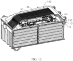
- FIG. 8 to FIG. 11 are schematic structural diagrams of a battery pack 1000 according to an embodiment of the present application.
- the battery pack 1000 includes the battery box body 1 according to the foregoing some embodiment, and a cell module 2 and a battery management system 3 that are disposed in the battery box body 1.
- the cell module 2 is disposed in the accommodation cavity 100.
- the fixing bracket 12 presses on the cell module 2.
- Four sidewalls of the housing 10 abut against outer sidewalls of the cell module 2 respectively to limit the displacement of the cell module 2 along an X axis (horizontal direction) and a Y axis (vertical direction).
- the fixing bracket 12 presses on the cell module 2 to limit the displacement of the cell module 2 along a Z axis.
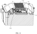
- the battery management system 3 is disposed on the fixing bracket 12 and abuts against the cover body 14.
- the battery management system 3 is provided with a fixing via hole 30.
- the position of the fixing via hole 30 corresponds to the position of the fixing structure 124 on the fixing bracket 12.
- the fixing structure 124 passes through the fixing via hole 30, thereby limiting the displacement of the battery management system 3 along the X axis (horizontal direction) and the Y axis (vertical direction).
- An inner sidewall of the cover body 14 abuts against the battery management system 3 to limit the displacement of the battery management system 3 along the Z axis.
- a radiator 31 is disposed on the battery management system 3.
- the radiator 31 is bonded to the cover body 14 by a thermally conductive adhesive 32.
- heat generated by an electronic component in the battery management system 3 is dissipated by the radiator 31 and the thermally conductive adhesive 32, and by a second heat sink 142 on the cover body 14.
- Heat generated by the cell module 2 is dissipated by first heat sinks 1010 at two sides of the housing 10 and by the partition plate 16.
- a pot gel may be disposed in the housing 10 to equalize and relieve the temperature of the cell module 2.
- the heat generated by the electronic component in the battery management system 3 is separated from the heat generated by the cell module 2.
- the two types of heat are dissipated by the second heat sink 142 on the cover body 14 and the first heat sink 1010 on the housing 10 respectively, thereby effectively enhancing the heat dissipation efficiency.
- the battery pack 1000 uses the battery box body to fix the battery management system 3 and the cell module 2 to achieve high structural stability, high mechanical capability, and high heat-dissipation efficiency.
- a battery box is further provided. Two or more battery packs 1000 described above are disposed in the battery box, so as to combine a plurality of battery packs.
Landscapes
- Chemical & Material Sciences (AREA)
- Chemical Kinetics & Catalysis (AREA)
- Electrochemistry (AREA)
- General Chemical & Material Sciences (AREA)
- Engineering & Computer Science (AREA)
- Manufacturing & Machinery (AREA)
- Microelectronics & Electronic Packaging (AREA)
- Aviation & Aerospace Engineering (AREA)
- Physics & Mathematics (AREA)
- Thermal Sciences (AREA)
- Inorganic Chemistry (AREA)
- Battery Mounting, Suspending (AREA)
Abstract
Description
- This application relates to the technical field of batteries, and in particular, to a battery box body, a battery pack, and a battery box.
- An electric vehicle is generally powered by electrical energy provided by a battery pack, so as to be driven to move. The battery pack generally includes a battery box body and a cell module accommodated in the battery box body. The battery box body serves main functions of supporting, fixing, and protecting the cell module, and needs to be of high mechanical strength, high electrical performance, high thermal performance, and high troubleshooting capabilities. Generally, all such factors are criteria for determining whether the battery pack is good or not. The battery box body in the prior art is complicated in structure, and is not satisfactory enough in thermal performance.
- In view of the foregoing, it is necessary to provide a battery box body, a battery pack, and a battery box to simplify the structure and provide high heat-dissipation performance.
- A battery box body is disclosed, including: a housing, provided with an accommodation cavity; a partition plate, disposed in the accommodation cavity, and configured to partition the accommodation cavity into a plurality of space blocks, where each space block is configured to receive a cell module; a fixing bracket, detachably disposed on the housing, and configured to fix a battery management system and the cell module to the housing, where two opposite sides of the fixing bracket abut against sidewalls of the housing respectively; and a cover body, detachably disposed on the housing and configured to cap the accommodation cavity.
- Optionally, the housing includes a plurality of sidewalls, guiding pieces are disposed on two opposite sidewalls respectively, and the fixing bracket is sandwiched between the two guiding pieces.
- Optionally, a side of the guiding piece opposite from a sidewall on which the guiding piece is located tilts against a plane of the sidewall, and the two guiding pieces are disposed parallel to each other.
- Optionally, the fixing bracket is connected onto the partition plate and the housing by means of snap-fastening and/or bolting.
- Optionally, a mounting portion is disposed on the sidewall of the housing, and the fixing bracket is fixed onto the mounting portion by a bolt.
- Optionally, the cover body is detachably disposed on the partition plate.
- Optionally, the fixing bracket is provided with a slot. The partition plate is provided with a hook, and the hook engages in the slot.
- Optionally, the partition plate includes a first end and a second end disposed opposite to each other, a gap is formed between the first end and the housing, and the second end is connected to a sidewall of the housing.
- Optionally, the partition plate is provided with a notch near the second end. The notch is configured to receive a wire harness for connecting the battery management system and the cell module.
- Optionally, both the partition plate and the housing are made of heat-dissipating materials.
- Optionally, a heat sink is disposed on both an outer side of the housing and an outer side of the cover body.
- Optionally, the cover body is provided with a pressing block. The pressing block presses on the fixing bracket, and a cushion is disposed between the pressing block and the fixing bracket.
- Optionally, a pressure sensor is disposed on the cushion and is configured to sense pressure exerted by the cover body on the fixing bracket.
- Optionally, a harness limiting structure is disposed on the fixing bracket, and is configured to limit a position of a wire harness in the battery box body.
- Optionally, the harness limiting structure includes a limiting block disposed protrusively on the fixing bracket. A limiting hole is disposed on the limiting block. The limiting hole is configured to allow a wire harness to pass through the hole.
- A battery pack is disclosed, including the foregoing battery box body, a cell module, and a battery management system. The cell module is accommodated in an accommodation cavity. A fixing bracket presses on the cell module. The battery management system is fixed on the fixing bracket and abuts against a cover body. Optionally, a radiator is disposed on the battery management system. The radiator is bonded to the cover body by a thermally conductive adhesive.
- Optionally, a pot gel is disposed in the housing. The pot gel is configured to equalize a temperature of the cell module.
- Optionally, a fixing structure is disposed on the fixing bracket, and is configured to limit a position of the battery management system.
- Optionally, the fixing structure is a protruding post disposed protrusively on the fixing bracket.
- Optionally, the protruding post is plural in number, and the plurality of protruding posts are disposed around the battery management system.
- A battery box is disclosed, including the foregoing battery pack.
- The battery box body is structurally simple and easy to assemble, and is of high mechanical strength and high heat-dissipation performance.
-
-
FIG. 1 is a schematic structural diagram of a battery box body according to an embodiment of the present application; -
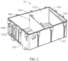
FIG. 2 is a schematic structural diagram of a housing of the battery box body shown inFIG. 1 ; -
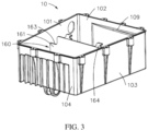
FIG. 3 is a schematic structural diagram of a housing of the battery box body shown inFIG. 1 from another viewing angle; -
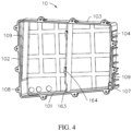
FIG. 4 is a schematic structural diagram of a housing of the battery box body shown inFIG. 1 from still another viewing angle; -
FIG. 5 is a schematic structural diagram of a fixing bracket of the battery box body shown inFIG. 1 ; -
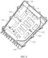
FIG. 6 is a schematic structural diagram of coordination between a housing and a fixing bracket of the battery box body shown inFIG. 1 ; -
FIG. 7 is a schematic structural diagram of a cover body of the battery box body shown inFIG. 1 ; -
FIG. 8 is a schematic structural diagram of a cover body of the battery box body shown inFIG. 1 from another viewing angle; -
FIG. 9 is a schematic structural diagram of a battery pack according to an embodiment of the present application; -
FIG. 10 is a schematic structural diagram of a part of section plane of the battery pack shown inFIG. 9 ; and -
FIG. 11 is a schematic structural diagram of a part of section plane of the battery pack shown inFIG. 9 . -
-
Battery box body 1 -
Housing 10 -
Accommodation cavity 100 -
First sidewall 101 -
Second sidewall 102 - Guiding structure 1020
-
Third sidewall 103 -
Fourth sidewall 104 -
Bottom plate 105 -
Partition plate 16 -
First end 161 -
Second end 162 -
Notch 163 -
Hook 164 - Gap 106
- First mounting
portion 107 - Third mounting
portion 108 - Guiding
piece 109 - Fixing
bracket 12 -
First side 120 -
Second side 121 - Second mounting
portion 122 -
Slot 123 - Fixing
structure 124 -
Harness limiting structure 125 -
Cushion 13 -
Pressure sensor 130 -
Cover body 14 - Fourth mounting
portion 140 - Pressing
block 141 -
Second heat sink 142 - Explosion-
proof valve 143 -
Battery pack 1000 -
Cell module 2 -
Battery management system 3 - Fixing via
hole 30 -
Radiator 31 - Thermally conductive adhesive 32
- The present application is further described below with reference to specific some embodiments and the foregoing drawings.
- The following clearly describes the technical solutions in some embodiments of the present application in full with reference to the accompanying drawings in some embodiments of the present application. Apparently, the described some embodiments are merely some of but not all of some embodiments of the present application. All other embodiments derived by a person of ordinary skill in the art based on some embodiments of the present application without making any creative efforts fall within the protection scope of the present application.
- Unless otherwise defined, all technical and scientific terms used herein have the same meanings as what is usually understood by a person skilled in the technical field of the present application. The terms used in the specification of the present application are merely intended for describing specific some embodiments but not intended for limiting the present application.
- The terms "first" and "second" used below are merely intended for descriptive purposes but are not to be understood as indicating or implying relative importance or as implicitly specifying the number of technical features indicated. Therefore, a feature qualified by "first", "second" and the like may explicitly or implicitly include one such feature or a plurality of the features. In the description of this application, unless otherwise specified, "a plurality of" means two or more. The directional terms such as "upper", "lower", "left", and "right" are defined relative to the orientation in which a component is schematically placed in the drawings. Understandably, the directional terms are relative concepts that are used for relative description and clarification, and may vary accordingly depending on the orientation of the component in the drawings.
- In this application, unless otherwise expressly specified and qualified, the term "connect" is understood in a broad sense. For example, a "connection" may be a fixed connection, a detachable connection, or an integrated whole, and may be a direct connection or an indirect connection implemented through an intermediary. The term "and/or" used herein includes any and all combinations of one or more related items preceding and following the term.
- When some embodiments are described below in detail with reference to schematic diagrams, for ease of description, a drawing that renders a partial structure of a device is not partially enlarged to scale. The schematic diagrams are merely examples, and do not hereby limit the protection scope of the present application.
- The battery box body and the battery pack according to some embodiments of this application are applicable to electronic devices, especially electric vehicles and the like.
- Refer to
FIG. 1 , which is a schematic structural diagram of abattery box body 1 according to an embodiment of the present application. Thebattery box body 1 includes ahousing 10, apartition plate 16, a fixingbracket 12, and acover body 14. The fixingbracket 12 is detachably disposed on thehousing 10. Thecover body 14 presses on the fixingbracket 12. - Referring to
FIG. 2 to FIG. 4 , thehousing 10 is roughly rectangular and is provided with anaccommodation cavity 100. Thehousing 10 includes afirst sidewall 101, asecond sidewall 102, athird sidewall 103, and afourth sidewall 104, and abottom plate 105 that is connected to thefirst sidewall 101, thesecond sidewall 102, and thefirst sidewall 103, and thefourth sidewall 104. Thefirst sidewall 101, thesecond sidewall 102, thethird sidewall 103, thefourth sidewall 104, and thebottom plate 105 close in to form theaccommodation cavity 100. Theaccommodation cavity 100 is configured to accommodate the cell module. In some embodiments, theaccommodation cavity 100 can accommodate two or more cell modules. Thepartition plate 16 is disposed in theaccommodation cavity 100, and is configured to partition theaccommodation cavity 100 into a plurality of space blocks. Each space block may be configured to receive a cell module. In an embodiment shown in the drawing, there is onepartition plate 16 that partitions theaccommodation cavity 100 into two space blocks. Understandably, the number ofpartition plates 16 may depend on the number of cell modules that need to be disposed. For example, if there are three cell modules, twopartition plates 16 may be disposed for partitioning. - The
partition plate 16 includes afirst end 161 and asecond end 162. Thefirst end 161 is opposite to thesecond end 162, and thesecond end 162 abuts against thethird sidewall 103 of thehousing 10. A gap 106 is disposed between thefirst end 161 and thefirst sidewall 101. Thefirst end 161 is also provided with anotch 163. Thegap 160 and thenotch 163 are configured to facilitate passage of a wire harness between the space blocks. - The
housing 10 is provided with a first mountingportion 107. The first mountingportion 107 is configured to mount and fix the fixingbracket 12. In an embodiment shown in the drawing, the first mountingportion 107 is a positioning hole. The fixingbracket 12 coordinates with the positioning hole through a bolt, so that the fixingbracket 12 is fastened onto thehousing 10. - Referring to
FIG. 5 andFIG. 6 , the fixingbracket 12 is configured to fix a battery management system (Battery Management System, BMS) and a cell module. The fixingbracket 12 includes afirst side 120 and asecond side 121 that is opposite to thefirst side 120. Thefirst side 120 abuts against thesecond side 121 on thesecond sidewall 102 and on thefourth sidewall 104 of thehousing 10 separately. The fixingbracket 12 is provided with a second mountingportion 122 corresponding to the first mountingportion 107. Thesecond mounting portion 122 is a via hole corresponding to the positioning hole. A bolt passes through the via hole and the positioning hole consecutively to fasten the fixingbracket 12 to thehousing 10. Understandably, in other embodiments, the means of fastening between the fixingbracket 12 and thehousing 10 is not limited to the positioning hole and the via hole shown in the drawing, but may be another similar fastening structure as long as the fastening structure can fasten the fixingbracket 12 onto thehousing 10. For example, the fastening structure may be a buckle structure. Either the fixingbracket 12 or thehousing 10 is provided with a slot, and the other is provided with a hook. The hook engages with the slot to serve a fastening function. - To further fix the fixing
bracket 12, the fixingbracket 12 may also be fastened to thepartition plate 16. In an embodiment shown in the drawing, thepartition plate 16 is provided with ahook 164, and the fixingbracket 12 is provided with aslot 123 correspondingly. Thehook 164 engages with theslot 123 to fasten the fixingbracket 12 to thepartition plate 16. Understandably, in other embodiments, the means of fastening the fixingbracket 12 to thepartition plate 16 is not limited to an embodiment shown in the drawing, but may be any other appropriate fastening means as long as the fastening means can fasten the fixingbracket 12 to thepartition plate 16. - To make it convenient to assemble the fixing
bracket 12 onto thehousing 10, thehousing 10 is provided with guidingpieces 109. The fixingbracket 12 is sandwiched between two guidingpieces 109. In an embodiment shown in the drawing, the guidingpieces 109 are guiding blocks disposed on thesecond sidewall 102 and thefourth sidewall 104. Each of the guiding blocks is a bevel structure. A side of the guiding block opposite from thesecond sidewall 102 or thefourth sidewall 104 tilts against a plane on which thesecond sidewall 102 or thefourth sidewall 104 is located. The guidingpiece 109 disposed on thesecond sidewall 102 is approximately parallel to the guiding piece disposed on thefourth sidewall 104. Understandably, in other embodiments, the guidingpiece 109 may be other structures as long as the structure facilitates mounting of the fixingbracket 12 onto thehousing 10. For example, thefirst side 120 and thesecond side 121 of the fixingbracket 12 may be provided with guiding strips. Thesecond sidewall 102 and thefourth sidewall 104 may be provided with guiding slots correspondingly. The guiding strips coordinate with the guiding slots so that the fixingbracket 12 is guided to be assembled onto thehousing 10. - The fixing
bracket 12 is configured to carry the battery management system. To make it convenient to limit the position of the battery management system module, the fixingbracket 12 is provided with a fixingstructure 124 configured to limit the position of the battery management system when the battery management system is carried on the fixingbracket 12, so that the position of the battery management system remains unchanged relative to the fixingbracket 12. In an embodiment shown in the drawing, the fixingstructure 124 is four protruding posts disposed protrusively on the fixingbracket 12 and configured to limit horizontal displacement and vertical displacement of the battery management system respectively. Understandably, in other embodiments, the limiting structure may be another structure that fits with the shape of the battery management system, such as a limiting slot, a limiting buckle, or the like. - In further some embodiments, the fixing
bracket 12 is further provided with aharness limiting structure 125. Theharness limiting structure 125 is configured to limit the position of a wire harness that passes through the structure. In an embodiment shown in the drawing, theharness limiting structure 125 is a limiting block that is disposed protrusively on a main body of the fixingbracket 12. The limiting block is provided with a limiting hole to allow the wire harness or a cable tie to pass through the limiting hole, thereby limiting the position of the wire harness or the cable tie. - Referring to
FIG. 7 andFIG. 8 , thecover body 14 detachably presses on thehousing 10 to cap theaccommodation cavity 100. An accommodation space enclosed between thecover body 14 and thepartition plate 16 is configured to allow for assembling of the battery management system. An accommodation space enclosed between thepartition plate 16 and thehousing 10 is configured to receive the cell module. - The
housing 10 is provided with a third mountingportion 108. Thecover body 14 is provided with a fourth mountingportion 140 correspondingly. Thethird mounting portion 108 coordinates with the fourth mountingportion 140 to fix thecover body 14 onto thehousing 10. In an embodiment shown in the drawing, the third mountingportion 108 is a screw hole, and the fourth mounting portion is a via hole. The bolt passes through the via hole and the screw hole to fasten thecover body 14 to thehousing 10. There are a plurality of screw holes, evenly distributed on the four sidewalls of thehousing 10. Understandably, in other embodiments, the means of fastening thehousing 10 to thecover body 14 is not limited to some embodiment shown in the drawing, but may be any other appropriate fastening structure as long as the fastening structure can fasten thecover body 14 to thehousing 10. For example, the fourth mountingportion 140 is a screw hole, and thehousing 10 is a via hole. - The
cover body 14 is provided with apressing block 141. Thepressing block 141 presses on the fixingbracket 12, so that the fixingbracket 12 is further fastened between thecover body 14 and thehousing 10. In some embodiment shown in the drawing, thepressing block 141 is disposed at two opposite sides of thecover body 14 separately and includes a plurality of pressing plates that are spaced apart. Understandably, in other embodiments, the shape of thepressing block 141 is not limited to some embodiment shown in the drawing. For example, there may be an integrated pressing block or several pressing blocks spaced apart, and the shape of the pressing block may be any appropriate geometric shapes such as a square or trapezoid. - In further some embodiments, a
cushion 13 is disposed between thepressing block 141 and the fixingbracket 12. Thecushion 13 is configured to buffer the pressure exerted by thecover body 14 on the fixingbracket 12. In some embodiments, thecushion 13 is a flexible rubber pad. Understandably, in other embodiments, thecushion 13 may be any material serving a function of buffering, such as sponge, silicone, and the like. - In further some embodiments, a pressure sensor 130 (shown in
FIG. 9 ) is disposed on thecushion 13. Thepressure sensor 130 is configured to sense pressure exerted by thecover body 14 on the fixingbracket 12. Thepressure sensor 130 can provide warning support when the pressure exceeds a preset value. - To facilitate dissipation of heat in the
battery box body 1, both thepartition plate 16 and thehousing 10 are made of heat-dissipating materials. To further improve the heat dissipation effect, a heat sink is disposed on both an outer side of thehousing 10 and an outer side of thecover body 14. As shown inFIG. 2 , afirst heat sink 1010 is disposed on thesecond sidewall 102. As shown inFIG. 7 , thesecond heat sink 142 is disposed at the top of thecover body 14. - The
cover body 14 is further provided with an explosion-proof valve 143. The explosion-proof valve 143 is configured to relieve the pressure when a gas pressure in thebattery box body 1 reaches a preset value, so as to prevent thebattery box body 1 from exploding due to excessive gas pressure in the box body. - In assembling the
battery box body 1, the fixingbracket 12 is fixed in coordination with thepartition plate 16 first, so that theslot 123 of the fixingbracket 12 engages firmly with thehook 164 on thepartition plate 16. Then a bolt passes through the second mountingportion 122 on the fixingbracket 12 and the first mountingportion 107 on thehousing 10 to fasten the fixingbracket 12 to thehousing 10. Then thehousing 10 is capped with thecover body 14 so that thepressing block 141 abuts against thecushion 13. A bolt passes through the fourth mountingportion 140 on thecover body 14 and the third mountingportion 108 on thehousing 10 to fasten thecover body 14 to thehousing 10. - The
battery box body 1 according to an embodiment of the present application is structurally simple and easy to assemble, and is of high heat-dissipation performance. Thecover body 14 abuts against the fixingbracket 12 through thepressing block 141 and thecushion 13, so that the fixingbracket 12 is fastened between thecover body 14 and thehousing 10 to prevent shaking up and down. - Refer to
FIG. 8 to FIG. 11 , which are schematic structural diagrams of abattery pack 1000 according to an embodiment of the present application. - The
battery pack 1000 includes thebattery box body 1 according to the foregoing some embodiment, and acell module 2 and abattery management system 3 that are disposed in thebattery box body 1. Thecell module 2 is disposed in theaccommodation cavity 100. The fixingbracket 12 presses on thecell module 2. Four sidewalls of thehousing 10 abut against outer sidewalls of thecell module 2 respectively to limit the displacement of thecell module 2 along an X axis (horizontal direction) and a Y axis (vertical direction). The fixingbracket 12 presses on thecell module 2 to limit the displacement of thecell module 2 along a Z axis. - The
battery management system 3 is disposed on the fixingbracket 12 and abuts against thecover body 14. Thebattery management system 3 is provided with a fixing viahole 30. The position of the fixing viahole 30 corresponds to the position of the fixingstructure 124 on the fixingbracket 12. The fixingstructure 124 passes through the fixing viahole 30, thereby limiting the displacement of thebattery management system 3 along the X axis (horizontal direction) and the Y axis (vertical direction). An inner sidewall of thecover body 14 abuts against thebattery management system 3 to limit the displacement of thebattery management system 3 along the Z axis. - A
radiator 31 is disposed on thebattery management system 3. Theradiator 31 is bonded to thecover body 14 by a thermally conductive adhesive 32. In this way, heat generated by an electronic component in thebattery management system 3 is dissipated by theradiator 31 and the thermally conductive adhesive 32, and by asecond heat sink 142 on thecover body 14. Heat generated by thecell module 2 is dissipated byfirst heat sinks 1010 at two sides of thehousing 10 and by thepartition plate 16. - In further some embodiments, to enhance the heat dissipation effect, a pot gel may be disposed in the
housing 10 to equalize and relieve the temperature of thecell module 2. - The heat generated by the electronic component in the
battery management system 3 is separated from the heat generated by thecell module 2. The two types of heat are dissipated by thesecond heat sink 142 on thecover body 14 and thefirst heat sink 1010 on thehousing 10 respectively, thereby effectively enhancing the heat dissipation efficiency. - The
battery pack 1000 uses the battery box body to fix thebattery management system 3 and thecell module 2 to achieve high structural stability, high mechanical capability, and high heat-dissipation efficiency. - In some embodiments of the present application, a battery box is further provided. Two or
more battery packs 1000 described above are disposed in the battery box, so as to combine a plurality of battery packs. - The foregoing descriptions are merely specific implementations of this application, but are not intended to limit the protection scope of this application. Any variations or replacements made within the technical scope disclosed herein fall within the protection scope of this application. Therefore, the protection scope of this application shall be subject to the protection scope of the claims.
Claims (19)
- A battery box body, wherein the battery box body comprises:a housing, provided with an accommodation cavity;a partition plate, disposed in the accommodation cavity, and configured to partition the accommodation cavity into a plurality of space blocks, wherein each space block is configured to receive a cell module;a fixing bracket, detachably disposed on the housing, and configured to fix a battery management system and the cell module to the housing, wherein two opposite sides of the fixing bracket abut against sidewalls of the housing respectively; anda cover body, detachably disposed on the housing and configured to cap the accommodation cavity.
- The battery box body according to claim 1, wherein the housing comprises a plurality of sidewalls, guiding pieces are disposed on two opposite sidewalls respectively, and the fixing bracket is sandwiched between the two guiding pieces.
- The battery box body according to claim 2, wherein a side of the guiding piece opposite from a sidewall on which the guiding piece is located tilts against a plane of the sidewall, and the two guiding pieces are disposed parallel to each other.
- The battery box body according to claim 1, wherein the fixing bracket is connected onto the partition plate and the housing by means of snap-fastening and/or bolting.
- The battery box body according to claim 4, wherein a mounting portion is disposed on the sidewall of the housing, and the fixing bracket is fixed onto the mounting portion by a bolt.
- The battery box body according to claim 1, wherein the cover body is detachably disposed on the partition plate.
- The battery box body according to claim 6, wherein the fixing bracket is provided with a slot, the partition plate is provided with a hook, and the hook engages in the slot.
- The battery box body according to claim 1, wherein the partition plate comprises a first end and a second end disposed opposite to each other, a gap is formed between the first end and the housing, and the second end is connected to a sidewall of the housing.
- The battery box body according to claim 8, wherein the partition plate is provided with a notch near the second end, and the notch is configured to receive a wire harness for connecting the battery management system and the cell module.
- The battery box body according to claim 1, wherein both the partition plate and the housing are made of heat-dissipating materials.
- The battery box body according to claim 1, wherein a heat sink is disposed on both an outer side of the housing and an outer side of the cover body.
- The battery box body according to claim 1, wherein the cover body is provided with a pressing block, the pressing block presses on the fixing bracket, and a cushion is disposed between the pressing block and the fixing bracket.
- The battery box body according to claim 12, wherein a pressure sensor is disposed on the cushion and is configured to sense pressure exerted by the cover body on the fixing bracket.
- The battery box body according to claim 1, wherein a harness limiting structure is disposed on the fixing bracket, and is configured to limit a position of a wire harness in the battery box body.
- A battery pack, comprising the battery box body according to any one of claims 1 to 10, a cell module, and a battery management system, wherein the cell module is accommodated in an accommodation cavity, a fixing bracket presses on the cell module, and the battery management system is fixed on the fixing bracket and abuts against a cover body.
- The battery pack according to claim 15, wherein a radiator is disposed on the battery management system, and the radiator is bonded to the cover body by a thermally conductive adhesive.
- The battery pack according to claim 15, wherein a pot gel is disposed in the housing, and the pot gel is configured to equalize a temperature of the cell module.
- The battery pack according to claim 15, wherein a fixing structure is disposed on the fixing bracket, and is configured to limit a position of the battery management system.
- A battery box, wherein the battery box comprises the battery pack according to any one of claims 15 to 18.
Applications Claiming Priority (1)
| Application Number | Priority Date | Filing Date | Title |
|---|---|---|---|
| PCT/CN2020/090899 WO2021232205A1 (en) | 2020-05-18 | 2020-05-18 | Battery box body, battery set, and battery box |
Publications (3)
| Publication Number | Publication Date |
|---|---|
| EP4152484A1 true EP4152484A1 (en) | 2023-03-22 |
| EP4152484A4 EP4152484A4 (en) | 2023-06-28 |
| EP4152484B1 EP4152484B1 (en) | 2026-02-25 |
Family
ID=78377825
Family Applications (1)
| Application Number | Title | Priority Date | Filing Date |
|---|---|---|---|
| EP20936668.1A Active EP4152484B1 (en) | 2020-05-18 | 2020-05-18 | Battery box body, battery set, and battery box |
Country Status (3)
| Country | Link |
|---|---|
| EP (1) | EP4152484B1 (en) |
| CN (1) | CN113632301B (en) |
| WO (1) | WO2021232205A1 (en) |
Cited By (1)
| Publication number | Priority date | Publication date | Assignee | Title |
|---|---|---|---|---|
| EP4531162A1 (en) * | 2023-09-28 | 2025-04-02 | Xiamen Ampack Technology Limited | Battery module, battery pack, and electrical device |
Families Citing this family (7)
| Publication number | Priority date | Publication date | Assignee | Title |
|---|---|---|---|---|
| CN114400404B (en) * | 2021-12-03 | 2024-03-26 | 苏州平峰科技有限公司 | Battery assembly and peak clipping and valley filling energy storage device with same |
| CN114828507B (en) * | 2022-03-22 | 2023-07-25 | 国网山东省电力公司惠民县供电公司 | A new type of power system communication management device |
| CN114824624B (en) * | 2022-03-29 | 2024-07-02 | 广船国际有限公司 | Battery installing support and boats and ships |
| CN115588557A (en) * | 2022-09-26 | 2023-01-10 | 华为数字能源技术有限公司 | Electromagnetic device and electronic apparatus |
| CN115588801A (en) * | 2022-12-12 | 2023-01-10 | 中国第一汽车股份有限公司 | Battery assembly, vehicle and battery system pressure early warning method of vehicle |
| TWI884626B (en) * | 2023-12-07 | 2025-05-21 | 融程電訊股份有限公司 | Electronic device with explosion-proof function and explosion-proof method |
| CN117895163B (en) * | 2024-03-18 | 2024-05-24 | 惠州市瑞能德电子有限公司 | Anti-seismic energy storage battery for forklift |
Family Cites Families (17)
| Publication number | Priority date | Publication date | Assignee | Title |
|---|---|---|---|---|
| CA2743467C (en) * | 2007-12-07 | 2013-01-15 | Allen-Vanguard Corporation | Apparatus and method for measuring and recording data from violent events |
| CN201238056Y (en) * | 2008-05-22 | 2009-05-13 | 中信国安盟固利新能源科技有限公司 | Lithium ion battery module with battery compressing structure |
| CN201540927U (en) * | 2009-09-24 | 2010-08-04 | 瑞能科技股份有限公司 | High-efficiency starter battery |
| JP5705972B2 (en) * | 2011-04-12 | 2015-04-22 | 日立オートモティブシステムズ株式会社 | Cell block |
| US9385355B2 (en) * | 2013-07-30 | 2016-07-05 | Johnson Controls Technology Company | System and method for crimping interconnection of battery cells |
| DE102014200983B4 (en) * | 2014-01-21 | 2023-12-14 | Robert Bosch Gmbh | Battery system with several battery cells and a housing, housing system for a battery and method for assembling a battery system |
| US9437850B2 (en) * | 2014-04-30 | 2016-09-06 | Johnson Controls Technology Company | Battery construction for integration of battery management system and method |
| KR20170003399A (en) * | 2015-06-30 | 2017-01-09 | 가부시키가이샤 지에스 유아사 | Energy storage apparatus |
| CN205016594U (en) * | 2015-10-13 | 2016-02-03 | 重庆长安汽车股份有限公司 | BMS installation fixed bolster, battery package and car |
| DE102016203553A1 (en) * | 2016-03-03 | 2017-09-07 | Volkswagen Aktiengesellschaft | Battery assembly and vehicle with such a battery assembly |
| CN108878698B (en) * | 2017-05-09 | 2021-08-13 | 华为技术有限公司 | Battery packs, battery energy storage systems and electric vehicles |
| CN208460828U (en) * | 2018-06-11 | 2019-02-01 | 广州小鹏汽车科技有限公司 | A bracket applied to a battery pack, a battery pack and an electric vehicle |
| CN209087996U (en) * | 2018-08-31 | 2019-07-09 | 深圳市大疆创新科技有限公司 | Battery and agriculture unmanned plane with the battery |
| CN110800129A (en) * | 2018-08-31 | 2020-02-14 | 深圳市大疆创新科技有限公司 | Battery and agricultural drone with the same |
| CN109244304A (en) * | 2018-10-23 | 2019-01-18 | 泰州瑞华新能源科技有限公司 | A kind of battery of electric vehicle group |
| CN209232838U (en) * | 2018-12-11 | 2019-08-09 | 北京汽车研究总院有限公司 | Power cell of vehicle system component and vehicle with it |
| CN209447945U (en) * | 2018-12-30 | 2019-09-27 | 宁德时代新能源科技股份有限公司 | A kind of battery pack |
-
2020
- 2020-05-18 EP EP20936668.1A patent/EP4152484B1/en active Active
- 2020-05-18 WO PCT/CN2020/090899 patent/WO2021232205A1/en not_active Ceased
- 2020-05-18 CN CN202080007071.8A patent/CN113632301B/en active Active
Cited By (1)
| Publication number | Priority date | Publication date | Assignee | Title |
|---|---|---|---|---|
| EP4531162A1 (en) * | 2023-09-28 | 2025-04-02 | Xiamen Ampack Technology Limited | Battery module, battery pack, and electrical device |
Also Published As
| Publication number | Publication date |
|---|---|
| WO2021232205A1 (en) | 2021-11-25 |
| EP4152484A4 (en) | 2023-06-28 |
| CN113632301A (en) | 2021-11-09 |
| EP4152484B1 (en) | 2026-02-25 |
| CN113632301B (en) | 2023-07-04 |
Similar Documents
| Publication | Publication Date | Title |
|---|---|---|
| EP4152484B1 (en) | Battery box body, battery set, and battery box | |
| US20230027497A1 (en) | Secondary Battery Module | |
| JP5236210B2 (en) | Battery module structure of the battery | |
| US9935345B2 (en) | Cooling structure of power storage device | |
| JP2026063093A (en) | Battery packs and electric vehicles | |
| KR20200112246A (en) | A battery module having a module housing of a thin plate type and a battery pack including the same | |
| JP2005317456A (en) | Battery pack | |
| ES3042246T3 (en) | Battery pack comprising battery frame | |
| CN108075070A (en) | Battery pack | |
| KR102880031B1 (en) | Battery module and battery pack including the same | |
| KR101835583B1 (en) | Case for energy storage system having mounting plate with opening and energy storage system including the same | |
| CN205801511U (en) | A kind of aircraft and power set, Power Component | |
| US20240113359A1 (en) | Liquid-cooled battery module and battery pack | |
| KR20190120154A (en) | Secondary battery module | |
| CN111244345A (en) | Battery module and have its unmanned aerial vehicle | |
| KR20220049190A (en) | Battery module and manufacturing method thereof | |
| KR20210048976A (en) | Battery module and battery pack including the same | |
| KR20190087781A (en) | Battery module and battery pack including the same | |
| CN115411421A (en) | Battery module, battery package and consumer | |
| CN117748010B (en) | Battery module, energy storage device and electric equipment | |
| US20190237723A1 (en) | Battery unit | |
| CN212277333U (en) | Battery box, group battery and battery box | |
| EP4318753A1 (en) | Battery module and electric apparatus | |
| CN221080231U (en) | Battery Pack | |
| CN223334903U (en) | Functional module and energy storage equipment |
Legal Events
| Date | Code | Title | Description |
|---|---|---|---|
| STAA | Information on the status of an ep patent application or granted ep patent |
Free format text: STATUS: THE INTERNATIONAL PUBLICATION HAS BEEN MADE |
|
| PUAI | Public reference made under article 153(3) epc to a published international application that has entered the european phase |
Free format text: ORIGINAL CODE: 0009012 |
|
| STAA | Information on the status of an ep patent application or granted ep patent |
Free format text: STATUS: REQUEST FOR EXAMINATION WAS MADE |
|
| 17P | Request for examination filed |
Effective date: 20221214 |
|
| AK | Designated contracting states |
Kind code of ref document: A1 Designated state(s): AL AT BE BG CH CY CZ DE DK EE ES FI FR GB GR HR HU IE IS IT LI LT LU LV MC MK MT NL NO PL PT RO RS SE SI SK SM TR |
|
| A4 | Supplementary search report drawn up and despatched |
Effective date: 20230526 |
|
| RIC1 | Information provided on ipc code assigned before grant |
Ipc: H01M 10/42 20060101ALI20230522BHEP Ipc: H01M 50/10 20210101AFI20230522BHEP |
|
| DAV | Request for validation of the european patent (deleted) | ||
| DAX | Request for extension of the european patent (deleted) | ||
| GRAP | Despatch of communication of intention to grant a patent |
Free format text: ORIGINAL CODE: EPIDOSNIGR1 |
|
| STAA | Information on the status of an ep patent application or granted ep patent |
Free format text: STATUS: GRANT OF PATENT IS INTENDED |
|
| RAP1 | Party data changed (applicant data changed or rights of an application transferred) |
Owner name: NINGDE AMPEREX TECHNOLOGY LIMITED |
|
| INTG | Intention to grant announced |
Effective date: 20250916 |
|
| GRAS | Grant fee paid |
Free format text: ORIGINAL CODE: EPIDOSNIGR3 |
|
| GRAA | (expected) grant |
Free format text: ORIGINAL CODE: 0009210 |
|
| STAA | Information on the status of an ep patent application or granted ep patent |
Free format text: STATUS: THE PATENT HAS BEEN GRANTED |
|
| AK | Designated contracting states |
Kind code of ref document: B1 Designated state(s): AL AT BE BG CH CY CZ DE DK EE ES FI FR GB GR HR HU IE IS IT LI LT LU LV MC MK MT NL NO PL PT RO RS SE SI SK SM TR |
|
| P01 | Opt-out of the competence of the unified patent court (upc) registered |
Free format text: CASE NUMBER: UPC_APP_0001534_4152484/2026 Effective date: 20260116 |
|
| REG | Reference to a national code |
Ref country code: CH Ref legal event code: F10 Free format text: ST27 STATUS EVENT CODE: U-0-0-F10-F00 (AS PROVIDED BY THE NATIONAL OFFICE) Effective date: 20260225 Ref country code: GB Ref legal event code: FG4D |
|
| REG | Reference to a national code |
Ref country code: DE Ref legal event code: R096 Ref document number: 602020067773 Country of ref document: DE |
|
| REG | Reference to a national code |
Ref country code: IE Ref legal event code: FG4D Ref country code: NL Ref legal event code: FP |