EP4152263A1 - Aircraft camera extrinsic calibration using head-up display - Google Patents
Aircraft camera extrinsic calibration using head-up display Download PDFInfo
- Publication number
- EP4152263A1 EP4152263A1 EP22195176.7A EP22195176A EP4152263A1 EP 4152263 A1 EP4152263 A1 EP 4152263A1 EP 22195176 A EP22195176 A EP 22195176A EP 4152263 A1 EP4152263 A1 EP 4152263A1
- Authority
- EP
- European Patent Office
- Prior art keywords
- boresight
- camera
- images
- features
- transformations
- Prior art date
- Legal status (The legal status is an assumption and is not a legal conclusion. Google has not performed a legal analysis and makes no representation as to the accuracy of the status listed.)
- Granted
Links
Images


Classifications
-
- G—PHYSICS
- G06—COMPUTING OR CALCULATING; COUNTING
- G06T—IMAGE DATA PROCESSING OR GENERATION, IN GENERAL
- G06T7/00—Image analysis
- G06T7/80—Analysis of captured images to determine intrinsic or extrinsic camera parameters, i.e. camera calibration
-
- G—PHYSICS
- G06—COMPUTING OR CALCULATING; COUNTING
- G06T—IMAGE DATA PROCESSING OR GENERATION, IN GENERAL
- G06T7/00—Image analysis
- G06T7/70—Determining position or orientation of objects or cameras
- G06T7/73—Determining position or orientation of objects or cameras using feature-based methods
-
- G—PHYSICS
- G06—COMPUTING OR CALCULATING; COUNTING
- G06T—IMAGE DATA PROCESSING OR GENERATION, IN GENERAL
- G06T7/00—Image analysis
- G06T7/30—Determination of transform parameters for the alignment of images, i.e. image registration
- G06T7/33—Determination of transform parameters for the alignment of images, i.e. image registration using feature-based methods
-
- G—PHYSICS
- G06—COMPUTING OR CALCULATING; COUNTING
- G06T—IMAGE DATA PROCESSING OR GENERATION, IN GENERAL
- G06T7/00—Image analysis
- G06T7/70—Determining position or orientation of objects or cameras
- G06T7/73—Determining position or orientation of objects or cameras using feature-based methods
- G06T7/74—Determining position or orientation of objects or cameras using feature-based methods involving reference images or patches
-
- G—PHYSICS
- G06—COMPUTING OR CALCULATING; COUNTING
- G06V—IMAGE OR VIDEO RECOGNITION OR UNDERSTANDING
- G06V10/00—Arrangements for image or video recognition or understanding
- G06V10/20—Image preprocessing
- G06V10/22—Image preprocessing by selection of a specific region containing or referencing a pattern; Locating or processing of specific regions to guide the detection or recognition
- G06V10/235—Image preprocessing by selection of a specific region containing or referencing a pattern; Locating or processing of specific regions to guide the detection or recognition based on user input or interaction
-
- G—PHYSICS
- G06—COMPUTING OR CALCULATING; COUNTING
- G06V—IMAGE OR VIDEO RECOGNITION OR UNDERSTANDING
- G06V10/00—Arrangements for image or video recognition or understanding
- G06V10/70—Arrangements for image or video recognition or understanding using pattern recognition or machine learning
- G06V10/74—Image or video pattern matching; Proximity measures in feature spaces
- G06V10/75—Organisation of the matching processes, e.g. simultaneous or sequential comparisons of image or video features; Coarse-fine approaches, e.g. multi-scale approaches; using context analysis; Selection of dictionaries
- G06V10/751—Comparing pixel values or logical combinations thereof, or feature values having positional relevance, e.g. template matching
-
- G—PHYSICS
- G02—OPTICS
- G02B—OPTICAL ELEMENTS, SYSTEMS OR APPARATUS
- G02B27/00—Optical systems or apparatus not provided for by any of the groups G02B1/00 - G02B26/00, G02B30/00
- G02B27/01—Head-up displays
- G02B27/0101—Head-up displays characterised by optical features
- G02B2027/0138—Head-up displays characterised by optical features comprising image capture systems, e.g. camera
-
- G—PHYSICS
- G02—OPTICS
- G02B—OPTICAL ELEMENTS, SYSTEMS OR APPARATUS
- G02B27/00—Optical systems or apparatus not provided for by any of the groups G02B1/00 - G02B26/00, G02B30/00
- G02B27/01—Head-up displays
- G02B27/0101—Head-up displays characterised by optical features
- G02B2027/014—Head-up displays characterised by optical features comprising information/image processing systems
-
- G—PHYSICS
- G02—OPTICS
- G02B—OPTICAL ELEMENTS, SYSTEMS OR APPARATUS
- G02B27/00—Optical systems or apparatus not provided for by any of the groups G02B1/00 - G02B26/00, G02B30/00
- G02B27/01—Head-up displays
- G02B27/0101—Head-up displays characterised by optical features
- G02B2027/0141—Head-up displays characterised by optical features characterised by the informative content of the display
-
- G—PHYSICS
- G02—OPTICS
- G02B—OPTICAL ELEMENTS, SYSTEMS OR APPARATUS
- G02B27/00—Optical systems or apparatus not provided for by any of the groups G02B1/00 - G02B26/00, G02B30/00
- G02B27/01—Head-up displays
- G02B27/0101—Head-up displays characterised by optical features
-
- G—PHYSICS
- G06—COMPUTING OR CALCULATING; COUNTING
- G06T—IMAGE DATA PROCESSING OR GENERATION, IN GENERAL
- G06T2207/00—Indexing scheme for image analysis or image enhancement
- G06T2207/20—Special algorithmic details
- G06T2207/20092—Interactive image processing based on input by user
- G06T2207/20101—Interactive definition of point of interest, landmark or seed
-
- G—PHYSICS
- G06—COMPUTING OR CALCULATING; COUNTING
- G06T—IMAGE DATA PROCESSING OR GENERATION, IN GENERAL
- G06T2207/00—Indexing scheme for image analysis or image enhancement
- G06T2207/30—Subject of image; Context of image processing
- G06T2207/30244—Camera pose
-
- G—PHYSICS
- G06—COMPUTING OR CALCULATING; COUNTING
- G06T—IMAGE DATA PROCESSING OR GENERATION, IN GENERAL
- G06T2207/00—Indexing scheme for image analysis or image enhancement
- G06T2207/30—Subject of image; Context of image processing
- G06T2207/30248—Vehicle exterior or interior
- G06T2207/30252—Vehicle exterior; Vicinity of vehicle
Definitions
- embodiments of the inventive concepts disclosed herein are directed to a system and method that utilizes an existing heads-up display (HUD) and a camera to determine the rotational relationship between the camera and the aircraft's boresight.
- HUD heads-up display
- Known boresight features are identified in a camera image, and transformations are applied to align pixels in the camera image to the known locations of the boresight features.
- object recognition algorithms are employed to identify the boresight features in the camera image.
- inventive concepts are not limited in their application to the details of construction and the arrangement of the components or steps or methodologies set forth in the following description or illustrated in the drawings.
- inventive concepts disclosed herein may be practiced without these specific details.
- well-known features may not be described in detail to avoid unnecessarily complicating the instant disclosure.
- inventive concepts disclosed herein are capable of other embodiments or of being practiced or carried out in various ways. Also, it is to be understood that the phraseology and terminology employed herein is for the purpose of description and should not be regarded as limiting.
- a letter following a reference numeral is intended to reference an embodiment of the feature or element that may be similar, but not necessarily identical, to a previously described element or feature bearing the same reference numeral (e.g., 1, 1a, 1b).
- reference numeral e.g. 1, 1a, 1b
- Such shorthand notations are used for purposes of convenience only, and should not be construed to limit the inventive concepts disclosed herein in any way unless expressly stated to the contrary.
- any reference to "one embodiment,” or “some embodiments” means that a particular element, feature, structure, or characteristic described in connection with the embodiment is included in at least one embodiment of the inventive concepts disclosed herein.
- the appearances of the phrase “in some embodiments” in various places in the specification are not necessarily all referring to the same embodiment, and embodiments of the inventive concepts disclosed may include one or more of the features expressly described or inherently present herein, or any combination of sub-combination of two or more such features, along with any other features which may not necessarily be expressly described or inherently present in the instant disclosure.
- embodiments of the inventive concepts disclosed herein are directed to a system and method that utilizes an existing HUD and a camera to determine the rotational relationship between the camera and the aircraft's boresight.
- Known boresight features are identified in a camera image, and transformations are applied to align pixels in the camera image to the known locations of the boresight features.
- Object recognition algorithms may be employed to identify the boresight features in the camera image.
- Embodiments of the present disclosure are useful for calibrating the rotational component of the camera installation relative to the vehicle body.
- the process to determine the rotational relationship between the camera and the vehicle involves a camera viewing through a HUD which has been previously boresighted to the vehicle and provides a collimated display of the boresight.
- the system includes a processor 100, memory 102 connected to the processor for storing processor executable code, a calibrated HUD system 104 with a boresight and boresight features, and a camera 106 to be calibrated.
- the camera 106 and calibrated HUD system 104 each capture substantially corresponding images showing image features that may be correlated.
- the processor 100 utilizes boresight features identifiable in the calibrated HUD system 104 to establish a relationship between image features from the calibrated HUD system 104 and the camera 106.
- the processor 100 determines a set of transformations to be applied to images from the camera 106 to conform to the calibrated HUD system 104.
- the set of transformations may be embodied in a matrix stored in a data storage element 110.
- images from the calibrated HUB system 104 may be captured via a handheld camera 108.
- An exemplary boresight feature includes a plurality of reference points 202, 204, 206 that define the boresight 200 (which may be free of direct symbology).
- the reference points 202, 204, 206 as defined by specific pixel locations, may be used to define a set of vectors with respect to the boresight features and specific pixels within an image.
- three orthogonal vectors may be utilized to isolate a spatial relationship between the boresight features and the vehicle where it is installed, for example, via the inverse product of the set of vectors and identity vectors corresponding to a specific spatial vector.
- Such isolated spatial relationships define a transformation relating images captured through a corresponding calibrated HUD system to the orientation of the vehicle (such as an aircraft).
- boresight and image features utilized in an exemplary embodiment is shown.
- boresight features 300 are related to the orientation of a vehicle.
- Image features 302, 304 within an image frame including the boresight features are identified.
- a corresponding camera in need of calibration may also capture a substantially simultaneous image including the image features 302, 304.
- a transformation may be determined to shift and rotate (align) subsequent images from the camera such that the images correspond to the orientation and alignment of the calibrated HUD system.
- a camera is positioned 400 within the view of a HUD having a boresight with one or more calibrated boresight features.
- One or more boresight images are captured 402, either directly via the HUD system or via a handheld camera.
- One or more overlapping images are captured 404 via the camera being calibrated.
- Common reference elements are identified 406 between the boresight images and the overlapping images, and the common reference elements are compared 408.
- a set of vectors are calculated referencing the boresight features to exterior features in the images. Such vectors may be determined by identifying specific coordinates within the images and calculating orthogonal vectors with reference to features in the boresight.
- the vectors may be related to the actual body of the vehicle via known calibration metrics of the HUD system to determine 410 a transformation matrix associating exterior image features to the boresight.
- the exterior features are identified by a user.
- object recognition algorithms such as edge detection
- exterior features should be sufficiently distant (“at infinity”), viewable both by the HUD system and the installed camera, and possess sharp, distinctly defined edges.
- Embodiments of the present disclosure enable an image shot through a HUD using any standard camera and a simultaneous image shot through a camera being calibrated to utilize the know calibration integrity of the HUD.
- the rotation between the HUD and the calibrating camera are related, as well as the rotation between the HUD and the vehicle to determine the final rotation between the calibrating camera and the vehicle.
- Such system allows for quick and arbitrary installation of a camera system on an aircraft with installation to be characterized. It does not require precise installation measurement.
Landscapes
- Engineering & Computer Science (AREA)
- Theoretical Computer Science (AREA)
- Computer Vision & Pattern Recognition (AREA)
- Physics & Mathematics (AREA)
- General Physics & Mathematics (AREA)
- Multimedia (AREA)
- Databases & Information Systems (AREA)
- Computing Systems (AREA)
- Artificial Intelligence (AREA)
- Evolutionary Computation (AREA)
- General Health & Medical Sciences (AREA)
- Medical Informatics (AREA)
- Software Systems (AREA)
- Health & Medical Sciences (AREA)
- Image Processing (AREA)
- Closed-Circuit Television Systems (AREA)
Abstract
Description
- Camera sensors for use on an aircraft for camera-based position estimation require precise alignment with the aircraft boresight during installation. Existing methods carefully measure the installation angles of the camera on the aircraft, but this is cumbersome and can lead to insufficient accuracy, especially for safe landing functions and autonomous operations. Efficient and accurate extrinsic calibration methods are needed to support camera-based aircraft position estimation.
- In one aspect, embodiments of the inventive concepts disclosed herein are directed to a system and method that utilizes an existing heads-up display (HUD) and a camera to determine the rotational relationship between the camera and the aircraft's boresight. Known boresight features are identified in a camera image, and transformations are applied to align pixels in the camera image to the known locations of the boresight features.
- In a further aspect, object recognition algorithms are employed to identify the boresight features in the camera image.
- It is to be understood that both the foregoing general description and the following detailed description are exemplary and explanatory only and should not restrict the scope of the claims. The accompanying drawings, which are incorporated in and constitute a part of the specification, illustrate exemplary embodiments of the inventive concepts disclosed herein and together with the general description, serve to explain the principles.
- The numerous advantages of the embodiments of the inventive concepts disclosed herein may be better understood by those skilled in the art by reference to the accompanying figures in which:
-
FIG. 1 shows a block diagram of a system according to an exemplary embodiment; -
FIG. 2 shows a boresight image and features utilized in an exemplary embodiment; -
FIG. 3 shows a boresight and image features utilized in an exemplary embodiment; -
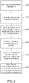
FIG. 4 shows a flowchart of a method according to an exemplary embodiment; - Before explaining at least one embodiment of the inventive concepts disclosed herein in detail, it is to be understood that the inventive concepts are not limited in their application to the details of construction and the arrangement of the components or steps or methodologies set forth in the following description or illustrated in the drawings. In the following detailed description of embodiments of the instant inventive concepts, numerous specific details are set forth in order to provide a more thorough understanding of the inventive concepts. However, it will be apparent to one of ordinary skill in the art having the benefit of the instant disclosure that the inventive concepts disclosed herein may be practiced without these specific details. In other instances, well-known features may not be described in detail to avoid unnecessarily complicating the instant disclosure. The inventive concepts disclosed herein are capable of other embodiments or of being practiced or carried out in various ways. Also, it is to be understood that the phraseology and terminology employed herein is for the purpose of description and should not be regarded as limiting.
- As used herein a letter following a reference numeral is intended to reference an embodiment of the feature or element that may be similar, but not necessarily identical, to a previously described element or feature bearing the same reference numeral (e.g., 1, 1a, 1b). Such shorthand notations are used for purposes of convenience only, and should not be construed to limit the inventive concepts disclosed herein in any way unless expressly stated to the contrary.
- Further, unless expressly stated to the contrary, "or" refers to an inclusive or and not to an exclusive or. For example, a condition A or B is satisfied by anyone of the following: A is true (or present) and B is false (or not present), A is false (or not present) and B is true (or present), and both A and B are true (or present).
- In addition, use of the "a" or "an" are employed to describe elements and components of embodiments of the instant inventive concepts. This is done merely for convenience and to give a general sense of the inventive concepts, and "a" and "an" are intended to include one or at least one and the singular also includes the plural unless it is obvious that it is meant otherwise.
- Finally, as used herein any reference to "one embodiment," or "some embodiments" means that a particular element, feature, structure, or characteristic described in connection with the embodiment is included in at least one embodiment of the inventive concepts disclosed herein. The appearances of the phrase "in some embodiments" in various places in the specification are not necessarily all referring to the same embodiment, and embodiments of the inventive concepts disclosed may include one or more of the features expressly described or inherently present herein, or any combination of sub-combination of two or more such features, along with any other features which may not necessarily be expressly described or inherently present in the instant disclosure.
- Broadly, embodiments of the inventive concepts disclosed herein are directed to a system and method that utilizes an existing HUD and a camera to determine the rotational relationship between the camera and the aircraft's boresight. Known boresight features are identified in a camera image, and transformations are applied to align pixels in the camera image to the known locations of the boresight features. Object recognition algorithms may be employed to identify the boresight features in the camera image.
- Embodiments of the present disclosure are useful for calibrating the rotational component of the camera installation relative to the vehicle body. The process to determine the rotational relationship between the camera and the vehicle involves a camera viewing through a HUD which has been previously boresighted to the vehicle and provides a collimated display of the boresight.
- Referring to
FIG. 1 , a block diagram of a system according to an exemplary embodiment is shown. The system includes a processor 100, memory 102 connected to the processor for storing processor executable code, a calibrated HUD system 104 with a boresight and boresight features, and a camera 106 to be calibrated. The camera 106 and calibrated HUD system 104 each capture substantially corresponding images showing image features that may be correlated. The processor 100 utilizes boresight features identifiable in the calibrated HUD system 104 to establish a relationship between image features from the calibrated HUD system 104 and the camera 106. The processor 100 determines a set of transformations to be applied to images from the camera 106 to conform to the calibrated HUD system 104. In at least one embodiment, the set of transformations may be embodied in a matrix stored in a data storage element 110. In at least one embodiment, images from the calibrated HUB system 104 may be captured via a handheld camera 108. - Referring to
FIG. 2 , a boresight image and features utilized in an exemplary embodiment is shown. An exemplary boresight feature includes a plurality ofreference points reference points - Referring to
FIG. 3 , a boresight and image features utilized in an exemplary embodiment is shown. In a calibrated HUD system with a boresight,boresight features 300 are related to the orientation of a vehicle. Image features 302, 304 within an image frame including the boresight features are identified. A corresponding camera in need of calibration may also capture a substantially simultaneous image including the image features 302, 304. Based on the calculated transformation relating images captured through a calibrated HUD system to the orientation of the vehicle, a transformation may be determined to shift and rotate (align) subsequent images from the camera such that the images correspond to the orientation and alignment of the calibrated HUD system. - Referring to
FIG. 4 , a flowchart of a method according to an exemplary embodiment is shown. A camera is positioned 400 within the view of a HUD having a boresight with one or more calibrated boresight features. One or more boresight images are captured 402, either directly via the HUD system or via a handheld camera. One or more overlapping images are captured 404 via the camera being calibrated. Common reference elements are identified 406 between the boresight images and the overlapping images, and the common reference elements are compared 408. In at least one embodiment, a set of vectors are calculated referencing the boresight features to exterior features in the images. Such vectors may be determined by identifying specific coordinates within the images and calculating orthogonal vectors with reference to features in the boresight. The vectors may be related to the actual body of the vehicle via known calibration metrics of the HUD system to determine 410 a transformation matrix associating exterior image features to the boresight. - In at least one embodiment, the exterior features are identified by a user. Alternatively, or in addition, object recognition algorithms (such as edge detection) may be employed to identify sufficiently distinct features to allow for near pixel level specificity. It may be appreciated that exterior features should be sufficiently distant ("at infinity"), viewable both by the HUD system and the installed camera, and possess sharp, distinctly defined edges.
- Embodiments of the present disclosure enable an image shot through a HUD using any standard camera and a simultaneous image shot through a camera being calibrated to utilize the know calibration integrity of the HUD. The rotation between the HUD and the calibrating camera are related, as well as the rotation between the HUD and the vehicle to determine the final rotation between the calibrating camera and the vehicle. Such system allows for quick and arbitrary installation of a camera system on an aircraft with installation to be characterized. It does not require precise installation measurement.
- It is believed that the inventive concepts disclosed herein and many of their attendant advantages will be understood by the foregoing description of embodiments of the inventive concepts disclosed, and it will be apparent that various changes may be made in the form, construction, and arrangement of the components thereof without departing from the broad scope of the inventive concepts disclosed herein or without sacrificing all of their material advantages; and individual features from various embodiments may be combined to arrive at other embodiments. The form herein before described being merely an explanatory embodiment thereof, it is the intention of the following claims to encompass and include such changes. Furthermore, any of the features disclosed in relation to any of the individual embodiments may be incorporated into any other embodiment.
Claims (15)
- A computer apparatus comprising:a camera (106); andat least one processor (100) in data communication with the camera (106) and a memory storing processor executable code for configuring the at least one processor (100) to:capture (402) one or more boresight images;capture (404) one or more images from the camera (106) overlapping the one or more boresight images;identify (406) common features within the one or more images and one or more boresight images;compare (408) the common features;determine (410) one or more transformations to apply to the one or more images based on comparison of common features; andstore the transformations for later application to future images from the camera (106).
- The computer apparatus of Claim 1, wherein identifying the common features comprises receiving a user input indicating a location of the image features, or wherein identifying the common features comprises object recognition algorithms.
- The computer apparatus of any preceding Claim, wherein the at least one processor (100) is further configured to identify boresight features by identifying three points within the boresight (200) to determine a camera orientation, and optionally wherein determining one or more transformations comprises establishing a vector relationship between the common features and the boresight features.
- The computer apparatus of any preceding Claim, wherein determining one or more transformations comprises generating a 3x3 matrix associated with the camera (106).
- The computer apparatus of any preceding Claim, wherein determining one or more transformations comprises:identifying a plurality of vectors; andcalculate cross-products of the plurality of vectors.
- A method comprising:capturing (402) one or more boresight images;capturing (404) one or more images from a camera (106) overlapping the one or more boresight images;identifying (406) common features within the one or more images and one or more boresight images;comparing (408) the common features;determining (410) one or more transformations to apply to the one or more images based on comparison of common features; andstoring the transformations for later application to future images from the camera (106).
- The method of Claim 6, wherein identifying the common features comprises receiving a user input indicating a location of the image features, or wherein identifying the common features comprises object recognition algorithms.
- The method of Claim 6 or 7, further comprising identifying boresight features by identifying three points within the boresight (200) to determine a camera orientation, and optionally wherein determining one or more transformations comprises establishing a vector relationship between the common features and the boresight features.
- The method of any of claims 6 to 7, wherein determining one or more transformations comprises generating a 3x3 matrix associated with the camera orientation, or wherein determining one or more transformations comprises:identifying a plurality of vectors; andcalculate cross-products of the plurality of vectors.
- A system comprising:a boresight (200);a camera (106); andat least one processor (100) in data communication with the camera (106) and a memory storing processor executable code for configuring the at least one processor (100) to:capture (402) one or more boresight images;identify boresight features by identifying three points within the boresight (200) to determine a camera orientation;capture (404) one or more images from the camera (106) overlapping the one or more boresight images;identify (406) common features within the one or more images and one or more boresight images;compare (408) the common features;determine (410) one or more transformations to apply to the one or more images based on comparison of common features; andstore the transformations for later application to future images from the camera (106).
- The system of Claim 10, wherein identifying the common features comprises receiving a user input indicating a location of the image features.
- The system of Claim 10, wherein identifying the common features comprises object recognition algorithms.
- The system of any of Claims 10 to 12, wherein determining one or more transformations comprises establishing a vector relationship between the common features and the boresight features.
- The system of any of Claims 10 to 12, wherein determining one or more transformations comprises generating a 3x3 matrix associated with the camera orientation.
- The system of any of Claims 1 to 12, wherein determining one or more transformations comprises:identifying a plurality of vectors; andcalculate cross-products of the plurality of vectors.
Applications Claiming Priority (1)
| Application Number | Priority Date | Filing Date | Title |
|---|---|---|---|
| US17/475,544 US12094167B2 (en) | 2021-09-15 | 2021-09-15 | Aircraft camera extrinsic calibration using head-up display |
Publications (2)
| Publication Number | Publication Date |
|---|---|
| EP4152263A1 true EP4152263A1 (en) | 2023-03-22 |
| EP4152263B1 EP4152263B1 (en) | 2025-07-02 |
Family
ID=83283517
Family Applications (1)
| Application Number | Title | Priority Date | Filing Date |
|---|---|---|---|
| EP22195176.7A Active EP4152263B1 (en) | 2021-09-15 | 2022-09-12 | Aircraft camera extrinsic calibration using head-up display |
Country Status (2)
| Country | Link |
|---|---|
| US (1) | US12094167B2 (en) |
| EP (1) | EP4152263B1 (en) |
Citations (3)
| Publication number | Priority date | Publication date | Assignee | Title |
|---|---|---|---|---|
| US4380024A (en) * | 1979-11-19 | 1983-04-12 | Olofsson Hasse E O | Airborne vehicle referenced (outside world) recording device utilizing an electro-optical camera and an electronic alignment procedure |
| JP2007147526A (en) * | 2005-11-30 | 2007-06-14 | Shimadzu Corp | Magnetic mapping apparatus and its mounting position correction method |
| KR20170057510A (en) * | 2015-11-16 | 2017-05-25 | 현대오트론 주식회사 | Apparatus for matching image of head-up display |
Family Cites Families (9)
| Publication number | Priority date | Publication date | Assignee | Title |
|---|---|---|---|---|
| GB2272343A (en) | 1992-11-10 | 1994-05-11 | Gec Ferranti Defence Syst | Automatic aircraft landing system calibration |
| US9418430B2 (en) * | 2013-10-03 | 2016-08-16 | Bae Systems Information And Electronic Systems Integration Inc. | Method and apparatus for establishing a north reference for inertial measurement units using scene correlation |
| US9897688B2 (en) * | 2013-11-30 | 2018-02-20 | Bae Systems Information And Electronic Systems Integration Inc. | Laser detection and image fusion system and method |
| WO2018053861A1 (en) * | 2016-09-26 | 2018-03-29 | SZ DJI Technology Co., Ltd. | Methods and system for vision-based landing |
| EP3529629B1 (en) * | 2016-10-20 | 2023-11-29 | Spookfish Innovations Pty Ltd. | An aerial camera boresight calibration system |
| US10573074B1 (en) * | 2017-03-21 | 2020-02-25 | Rockwell Collins, Inc. | Evaluating display accuracy |
| US11610337B2 (en) * | 2019-02-17 | 2023-03-21 | Purdue Research Foundation | Calibration of cameras and scanners on UAV and mobile platforms |
| US10943368B1 (en) * | 2019-04-12 | 2021-03-09 | Aurora Innovation, Inc. | Camera calibration system |
| US10997737B2 (en) * | 2019-05-02 | 2021-05-04 | GM Global Technology Operations LLC | Method and system for aligning image data from a vehicle camera |
-
2021
- 2021-09-15 US US17/475,544 patent/US12094167B2/en active Active
-
2022
- 2022-09-12 EP EP22195176.7A patent/EP4152263B1/en active Active
Patent Citations (3)
| Publication number | Priority date | Publication date | Assignee | Title |
|---|---|---|---|---|
| US4380024A (en) * | 1979-11-19 | 1983-04-12 | Olofsson Hasse E O | Airborne vehicle referenced (outside world) recording device utilizing an electro-optical camera and an electronic alignment procedure |
| JP2007147526A (en) * | 2005-11-30 | 2007-06-14 | Shimadzu Corp | Magnetic mapping apparatus and its mounting position correction method |
| KR20170057510A (en) * | 2015-11-16 | 2017-05-25 | 현대오트론 주식회사 | Apparatus for matching image of head-up display |
Also Published As
| Publication number | Publication date |
|---|---|
| EP4152263B1 (en) | 2025-07-02 |
| US20230082417A1 (en) | 2023-03-16 |
| US12094167B2 (en) | 2024-09-17 |
Similar Documents
| Publication | Publication Date | Title |
|---|---|---|
| US10719955B2 (en) | Camera extrinsic parameters estimation from image lines | |
| US10726576B2 (en) | System and method for identifying a camera pose of a forward facing camera in a vehicle | |
| EP1596332A2 (en) | Information processing method and apparatus for finding position and orientation of targeted object | |
| US20110228052A1 (en) | Three-dimensional measurement apparatus and method | |
| EP3032818B1 (en) | Image processing device | |
| GB2602588A (en) | Electronic device for automated user identification | |
| JP2017520063A5 (en) | ||
| US12067162B2 (en) | Gaze point detection device and gaze point detection method | |
| US20170146799A1 (en) | Coordinate matching apparatus for head-up display | |
| CN102270344A (en) | Moving object detection apparatus and moving object detection method | |
| EP3745359B1 (en) | Image recognition system and method | |
| CN111735439A (en) | Map construction method, apparatus and computer readable storage medium | |
| KR20160090677A (en) | Parking guide system and method for controlling the same | |
| JP2008131250A (en) | On-vehicle camera calibration device and vehicle production method using the device | |
| EP4224841A1 (en) | System and method for dynamic stereoscopic calibration | |
| WO2016113875A1 (en) | Information presentation system for evaluating billing location | |
| CN100410622C (en) | Information processing method and device for obtaining position and orientation of target object | |
| US20100092033A1 (en) | Method for target geo-referencing using video analytics | |
| JP2002063567A (en) | Device and method for estimating body position and attitude, method for feature point extraction method using the same, and image collating method | |
| CN110232676B (en) | Installation state detection method, device, equipment and system of aircraft cable support | |
| US20260057610A1 (en) | Reliability calculation device, three-dimensional information generation device, and reliability calculation method | |
| US12094167B2 (en) | Aircraft camera extrinsic calibration using head-up display | |
| EP2960622B1 (en) | A method for estimating a distance from a first communication device to a second communication device, and corresponding communication devices, server and system. | |
| KR101957662B1 (en) | Apparatus for calculating target information, method thereof and flight control system comprising the same | |
| US20070058885A1 (en) | Method and system for image registration quality confirmation and improvement |
Legal Events
| Date | Code | Title | Description |
|---|---|---|---|
| PUAI | Public reference made under article 153(3) epc to a published international application that has entered the european phase |
Free format text: ORIGINAL CODE: 0009012 |
|
| STAA | Information on the status of an ep patent application or granted ep patent |
Free format text: STATUS: THE APPLICATION HAS BEEN PUBLISHED |
|
| AK | Designated contracting states |
Kind code of ref document: A1 Designated state(s): AL AT BE BG CH CY CZ DE DK EE ES FI FR GB GR HR HU IE IS IT LI LT LU LV MC MK MT NL NO PL PT RO RS SE SI SK SM TR |
|
| STAA | Information on the status of an ep patent application or granted ep patent |
Free format text: STATUS: REQUEST FOR EXAMINATION WAS MADE |
|
| 17P | Request for examination filed |
Effective date: 20230921 |
|
| RBV | Designated contracting states (corrected) |
Designated state(s): AL AT BE BG CH CY CZ DE DK EE ES FI FR GB GR HR HU IE IS IT LI LT LU LV MC MK MT NL NO PL PT RO RS SE SI SK SM TR |
|
| GRAP | Despatch of communication of intention to grant a patent |
Free format text: ORIGINAL CODE: EPIDOSNIGR1 |
|
| STAA | Information on the status of an ep patent application or granted ep patent |
Free format text: STATUS: GRANT OF PATENT IS INTENDED |
|
| INTG | Intention to grant announced |
Effective date: 20250221 |
|
| GRAS | Grant fee paid |
Free format text: ORIGINAL CODE: EPIDOSNIGR3 |
|
| GRAA | (expected) grant |
Free format text: ORIGINAL CODE: 0009210 |
|
| STAA | Information on the status of an ep patent application or granted ep patent |
Free format text: STATUS: THE PATENT HAS BEEN GRANTED |
|
| AK | Designated contracting states |
Kind code of ref document: B1 Designated state(s): AL AT BE BG CH CY CZ DE DK EE ES FI FR GB GR HR HU IE IS IT LI LT LU LV MC MK MT NL NO PL PT RO RS SE SI SK SM TR |
|
| REG | Reference to a national code |
Ref country code: GB Ref legal event code: FG4D |
|
| REG | Reference to a national code |
Ref country code: CH Ref legal event code: EP |
|
| REG | Reference to a national code |
Ref country code: DE Ref legal event code: R096 Ref document number: 602022016769 Country of ref document: DE |
|
| REG | Reference to a national code |
Ref country code: IE Ref legal event code: FG4D |
|
| PGFP | Annual fee paid to national office [announced via postgrant information from national office to epo] |
Ref country code: DE Payment date: 20250820 Year of fee payment: 4 |
|
| PGFP | Annual fee paid to national office [announced via postgrant information from national office to epo] |
Ref country code: FR Payment date: 20250821 Year of fee payment: 4 Ref country code: AT Payment date: 20251020 Year of fee payment: 4 |
|
| REG | Reference to a national code |
Ref country code: NL Ref legal event code: MP Effective date: 20250702 |
|
| PG25 | Lapsed in a contracting state [announced via postgrant information from national office to epo] |
Ref country code: PT Free format text: LAPSE BECAUSE OF FAILURE TO SUBMIT A TRANSLATION OF THE DESCRIPTION OR TO PAY THE FEE WITHIN THE PRESCRIBED TIME-LIMIT Effective date: 20251103 |
|
| PG25 | Lapsed in a contracting state [announced via postgrant information from national office to epo] |
Ref country code: NL Free format text: LAPSE BECAUSE OF FAILURE TO SUBMIT A TRANSLATION OF THE DESCRIPTION OR TO PAY THE FEE WITHIN THE PRESCRIBED TIME-LIMIT Effective date: 20250702 |
|
| REG | Reference to a national code |
Ref country code: AT Ref legal event code: MK05 Ref document number: 1810136 Country of ref document: AT Kind code of ref document: T Effective date: 20250702 |
|
| PG25 | Lapsed in a contracting state [announced via postgrant information from national office to epo] |
Ref country code: IS Free format text: LAPSE BECAUSE OF FAILURE TO SUBMIT A TRANSLATION OF THE DESCRIPTION OR TO PAY THE FEE WITHIN THE PRESCRIBED TIME-LIMIT Effective date: 20251102 |
|
| PG25 | Lapsed in a contracting state [announced via postgrant information from national office to epo] |
Ref country code: NO Free format text: LAPSE BECAUSE OF FAILURE TO SUBMIT A TRANSLATION OF THE DESCRIPTION OR TO PAY THE FEE WITHIN THE PRESCRIBED TIME-LIMIT Effective date: 20251002 |
|
| REG | Reference to a national code |
Ref country code: LT Ref legal event code: MG9D |
|
| PG25 | Lapsed in a contracting state [announced via postgrant information from national office to epo] |
Ref country code: AT Free format text: LAPSE BECAUSE OF FAILURE TO SUBMIT A TRANSLATION OF THE DESCRIPTION OR TO PAY THE FEE WITHIN THE PRESCRIBED TIME-LIMIT Effective date: 20250702 |
|
| PG25 | Lapsed in a contracting state [announced via postgrant information from national office to epo] |
Ref country code: FI Free format text: LAPSE BECAUSE OF FAILURE TO SUBMIT A TRANSLATION OF THE DESCRIPTION OR TO PAY THE FEE WITHIN THE PRESCRIBED TIME-LIMIT Effective date: 20250702 |
|
| PG25 | Lapsed in a contracting state [announced via postgrant information from national office to epo] |
Ref country code: HR Free format text: LAPSE BECAUSE OF FAILURE TO SUBMIT A TRANSLATION OF THE DESCRIPTION OR TO PAY THE FEE WITHIN THE PRESCRIBED TIME-LIMIT Effective date: 20250702 |
|
| PG25 | Lapsed in a contracting state [announced via postgrant information from national office to epo] |
Ref country code: GR Free format text: LAPSE BECAUSE OF FAILURE TO SUBMIT A TRANSLATION OF THE DESCRIPTION OR TO PAY THE FEE WITHIN THE PRESCRIBED TIME-LIMIT Effective date: 20251003 |
|
| PG25 | Lapsed in a contracting state [announced via postgrant information from national office to epo] |
Ref country code: CZ Free format text: LAPSE BECAUSE OF FAILURE TO SUBMIT A TRANSLATION OF THE DESCRIPTION OR TO PAY THE FEE WITHIN THE PRESCRIBED TIME-LIMIT Effective date: 20250702 Ref country code: SE Free format text: LAPSE BECAUSE OF FAILURE TO SUBMIT A TRANSLATION OF THE DESCRIPTION OR TO PAY THE FEE WITHIN THE PRESCRIBED TIME-LIMIT Effective date: 20250702 |
|
| PG25 | Lapsed in a contracting state [announced via postgrant information from national office to epo] |
Ref country code: LV Free format text: LAPSE BECAUSE OF FAILURE TO SUBMIT A TRANSLATION OF THE DESCRIPTION OR TO PAY THE FEE WITHIN THE PRESCRIBED TIME-LIMIT Effective date: 20250702 |
|
| PG25 | Lapsed in a contracting state [announced via postgrant information from national office to epo] |
Ref country code: PL Free format text: LAPSE BECAUSE OF FAILURE TO SUBMIT A TRANSLATION OF THE DESCRIPTION OR TO PAY THE FEE WITHIN THE PRESCRIBED TIME-LIMIT Effective date: 20250702 Ref country code: BG Free format text: LAPSE BECAUSE OF FAILURE TO SUBMIT A TRANSLATION OF THE DESCRIPTION OR TO PAY THE FEE WITHIN THE PRESCRIBED TIME-LIMIT Effective date: 20250702 |
|
| PG25 | Lapsed in a contracting state [announced via postgrant information from national office to epo] |
Ref country code: RS Free format text: LAPSE BECAUSE OF FAILURE TO SUBMIT A TRANSLATION OF THE DESCRIPTION OR TO PAY THE FEE WITHIN THE PRESCRIBED TIME-LIMIT Effective date: 20251002 |
|
| PG25 | Lapsed in a contracting state [announced via postgrant information from national office to epo] |
Ref country code: ES Free format text: LAPSE BECAUSE OF FAILURE TO SUBMIT A TRANSLATION OF THE DESCRIPTION OR TO PAY THE FEE WITHIN THE PRESCRIBED TIME-LIMIT Effective date: 20250702 |
|
| PG25 | Lapsed in a contracting state [announced via postgrant information from national office to epo] |
Ref country code: RO Free format text: LAPSE BECAUSE OF FAILURE TO SUBMIT A TRANSLATION OF THE DESCRIPTION OR TO PAY THE FEE WITHIN THE PRESCRIBED TIME-LIMIT Effective date: 20250702 |
|
| PG25 | Lapsed in a contracting state [announced via postgrant information from national office to epo] |
Ref country code: SM Free format text: LAPSE BECAUSE OF FAILURE TO SUBMIT A TRANSLATION OF THE DESCRIPTION OR TO PAY THE FEE WITHIN THE PRESCRIBED TIME-LIMIT Effective date: 20250702 |
|
| PG25 | Lapsed in a contracting state [announced via postgrant information from national office to epo] |
Ref country code: DK Free format text: LAPSE BECAUSE OF FAILURE TO SUBMIT A TRANSLATION OF THE DESCRIPTION OR TO PAY THE FEE WITHIN THE PRESCRIBED TIME-LIMIT Effective date: 20250702 |
|
| PG25 | Lapsed in a contracting state [announced via postgrant information from national office to epo] |
Ref country code: IT Free format text: LAPSE BECAUSE OF FAILURE TO SUBMIT A TRANSLATION OF THE DESCRIPTION OR TO PAY THE FEE WITHIN THE PRESCRIBED TIME-LIMIT Effective date: 20250702 |
|
| REG | Reference to a national code |
Ref country code: CH Ref legal event code: H13 Free format text: ST27 STATUS EVENT CODE: U-0-0-H10-H13 (AS PROVIDED BY THE NATIONAL OFFICE) Effective date: 20260425 |
|
| PG25 | Lapsed in a contracting state [announced via postgrant information from national office to epo] |
Ref country code: EE Free format text: LAPSE BECAUSE OF FAILURE TO SUBMIT A TRANSLATION OF THE DESCRIPTION OR TO PAY THE FEE WITHIN THE PRESCRIBED TIME-LIMIT Effective date: 20250702 Ref country code: SK Free format text: LAPSE BECAUSE OF FAILURE TO SUBMIT A TRANSLATION OF THE DESCRIPTION OR TO PAY THE FEE WITHIN THE PRESCRIBED TIME-LIMIT Effective date: 20250702 |
|
| PLBE | No opposition filed within time limit |
Free format text: ORIGINAL CODE: 0009261 |
|
| STAA | Information on the status of an ep patent application or granted ep patent |
Free format text: STATUS: NO OPPOSITION FILED WITHIN TIME LIMIT |