EP4152254A1 - Target object positioning method and apparatus, device, medium, and program product - Google Patents
Target object positioning method and apparatus, device, medium, and program product Download PDFInfo
- Publication number
- EP4152254A1 EP4152254A1 EP21803947.7A EP21803947A EP4152254A1 EP 4152254 A1 EP4152254 A1 EP 4152254A1 EP 21803947 A EP21803947 A EP 21803947A EP 4152254 A1 EP4152254 A1 EP 4152254A1
- Authority
- EP
- European Patent Office
- Prior art keywords
- envelope region
- volume data
- region
- dimensional volume
- envelope
- Prior art date
- Legal status (The legal status is an assumption and is not a legal conclusion. Google has not performed a legal analysis and makes no representation as to the accuracy of the status listed.)
- Granted
Links
Images



Classifications
-
- G—PHYSICS
- G06—COMPUTING OR CALCULATING; COUNTING
- G06T—IMAGE DATA PROCESSING OR GENERATION, IN GENERAL
- G06T7/00—Image analysis
- G06T7/70—Determining position or orientation of objects or cameras
- G06T7/73—Determining position or orientation of objects or cameras using feature-based methods
-
- G—PHYSICS
- G06—COMPUTING OR CALCULATING; COUNTING
- G06T—IMAGE DATA PROCESSING OR GENERATION, IN GENERAL
- G06T7/00—Image analysis
- G06T7/10—Segmentation; Edge detection
- G06T7/11—Region-based segmentation
-
- G—PHYSICS
- G06—COMPUTING OR CALCULATING; COUNTING
- G06T—IMAGE DATA PROCESSING OR GENERATION, IN GENERAL
- G06T7/00—Image analysis
- G06T7/0002—Inspection of images, e.g. flaw detection
-
- G—PHYSICS
- G06—COMPUTING OR CALCULATING; COUNTING
- G06T—IMAGE DATA PROCESSING OR GENERATION, IN GENERAL
- G06T7/00—Image analysis
- G06T7/60—Analysis of geometric attributes
- G06T7/62—Analysis of geometric attributes of area, perimeter, diameter or volume
-
- G—PHYSICS
- G06—COMPUTING OR CALCULATING; COUNTING
- G06T—IMAGE DATA PROCESSING OR GENERATION, IN GENERAL
- G06T2207/00—Indexing scheme for image analysis or image enhancement
- G06T2207/10—Image acquisition modality
- G06T2207/10004—Still image; Photographic image
- G06T2207/10012—Stereo images
-
- G—PHYSICS
- G06—COMPUTING OR CALCULATING; COUNTING
- G06T—IMAGE DATA PROCESSING OR GENERATION, IN GENERAL
- G06T2207/00—Indexing scheme for image analysis or image enhancement
- G06T2207/10—Image acquisition modality
- G06T2207/10072—Tomographic images
- G06T2207/10081—Computed x-ray tomography [CT]
-
- G—PHYSICS
- G06—COMPUTING OR CALCULATING; COUNTING
- G06T—IMAGE DATA PROCESSING OR GENERATION, IN GENERAL
- G06T2207/00—Indexing scheme for image analysis or image enhancement
- G06T2207/20—Special algorithmic details
- G06T2207/20081—Training; Learning
-
- G—PHYSICS
- G06—COMPUTING OR CALCULATING; COUNTING
- G06T—IMAGE DATA PROCESSING OR GENERATION, IN GENERAL
- G06T2207/00—Indexing scheme for image analysis or image enhancement
- G06T2207/30—Subject of image; Context of image processing
- G06T2207/30108—Industrial image inspection
- G06T2207/30112—Baggage; Luggage; Suitcase
Definitions
- Embodiments of the present disclosure relate to a radiation imaging, and in particular, to a method and an apparatus of positioning a target object, a device, a medium and a program product.
- a method and an apparatus of positioning a target object, a device, a medium and a program product are provided.
- a method of positioning a target object including: acquiring first three-dimensional volume data of a checked baggage; generating a projected image of the checked baggage in a direction based on the first three-dimensional volume data; segmenting second three-dimensional volume data from the first three-dimensional volume data based on the projected image; determining at least one envelope region for at least one object in the checked baggage based on the second three-dimensional volume data; and determining an envelope region of the target object from the determined at least one envelope region.
- the above-mentioned segmenting second three-dimensional volume data from the first three-dimensional volume data based on the projected image includes: forming a two-dimensional effective region in the projected image; extending the two-dimensional effective region in the direction to form a cylindrical three-dimensional region with the two-dimensional effective region as a cross section; and determining three-dimensional volume data for the cylindrical three-dimensional region as the second three-dimensional volume data.
- the above-mentioned forming a two-dimensional effective region in the projected image includes: acquiring a size parameter for a predetermined shape; and generating, based on a first trigger operation for a designated point in the projected image, the two-dimensional effective region of the predetermined shape centered on the designated point and conforming to the size parameter.
- the above-mentioned acquiring a size parameter for a predetermined shape includes: acquiring the size parameter for the predetermined shape pre-configured in a configuration table.
- the above-mentioned acquiring a size parameter for a predetermined shape includes: determining the size parameter for the predetermined shape according to a size parameter for the projected image, so that the size parameter for the predetermined shape is in a predetermined proportion to the size parameter for the projected image.
- the above-mentioned determining at least one envelope region for at least one object in the checked baggage based on the second three-dimensional volume data includes: segmenting, from the second three-dimensional volume data, at least one set of three-dimensional volume data conforming to a predetermined image feature by using an image recognition algorithm; and determining the at least one envelope region according to the at least one set of three-dimensional volume data.
- the above-mentioned determining an envelope region of the target object from the at least one envelope region includes: calculating a priority of each of the at least one envelope region; sequentially displaying the at least one envelope region in an order of the calculated priorities being decreased; and determining an envelope region in the at least one envelope region as the envelope region of the target object based on a second trigger operation for the envelope region in the at least one envelope region.
- the above-mentioned calculating a priority of each of the at least one envelope region includes: for each of the at least one envelope region, acquiring an attribute parameter of the envelope region; and calculating the priority of the envelope region according to the attribute parameter.
- the above-mentioned acquiring an attribute parameter of the envelope region includes at least one of: calculating a volume of the envelope region according to three-dimensional volume data of the envelope region; calculating a density of the envelope region according to the three-dimensional volume data of the envelope region; and calculating a position coordinate of the envelope region in the projected image according to the three-dimensional volume data of the envelope region.
- the above-mentioned sequentially displaying the at least one envelope region in an order of the priorities being decreased includes: ranking the at least one envelope region according to the order of the priorities being decreased, so as to obtain a display sequence; displaying starting from a first envelope region in the display sequence; and when an image of an envelope region in the display sequence is displayed, switching, based on a third trigger operation for the envelope region in the display sequence, to display a posterior envelope region of the envelope region in the display sequence; and switching, based on a fourth trigger operation for the envelope region in the display sequence, to display the first envelope region displayed in the display sequence.
- the above-mentioned method further includes: after determining the envelope region in the at least one envelope region as the envelope region of the target object, adding a label to the envelope region; and adding and storing three-dimensional volume data of the envelope region in association with the label into a predetermined storage region.
- the above-mentioned acquiring first three-dimensional volume data of a checked baggage includes: acquiring the first three-dimensional volume data of the checked baggage by using a computed tomography device.
- an apparatus of positioning a target object including: an acquisition module, a projection module, a segmentation module, a determination module and a positioning module.
- the acquisition module is configured to acquire first three-dimensional volume data of a checked baggage.
- the projection module is configured to generate a projected image of the checked baggage in a direction based on the first three-dimensional volume data.
- the segmentation module is configured to segment second three-dimensional volume data from the first three-dimensional volume data based on the projected image.
- the determination module is configured to determine at least one envelope region for at least one object in the checked baggage based on the second three-dimensional volume data.
- the positioning module is configured to determine an envelope region of the target object from the determined at least one envelope region.
- an electronic device including a memory and at least one processor.
- the memory is configured to store instructions.
- the at least one processor executes the instructions stored in the memory, so as to implement the method as described in any of above-mentioned embodiments.
- a computer-readable storage medium having computer instructions stored thereon is provided, and the computer instructions, when executed by a processor, implement the method as described in any of above-mentioned embodiments.
- a computer program product including executable instructions is provided, and the executable instructions, when executed by a processor, implement the method as described in any of above-mentioned embodiments.
- a projection may be performed in a direction only, and the second three-dimensional volume data of some regions may be segmented from the first three-dimensional volume data of the checked baggage according to the projected image, which may greatly reduce a positioning range of the target object. Furthermore, the envelope region of each of the at least one object contained in the checked baggage is determined based on the second three-dimensional volume data, so as to determine the envelope region of the target object from the at least one envelope region.
- a reduction in the positioning range may simplify a positioning process of the target object, and improve an efficiency and an accuracy of target object positioning.
- Embodiments of the present disclosure provide a method and an apparatus of positioning a target object, a device, a medium and a program product.
- the method of positioning the target object may include an acquisition process, a projection process, a segmentation process, a determination process and a positioning process.
- the acquisition process first three-dimensional volume data of a checked baggage is acquired.
- the projection process is performed, in which a projected image of the checked baggage in a direction is generated based on the first three-dimensional volume data.
- second three-dimensional volume data is segmented from the first three-dimensional volume data based on the projected image.
- the determination process at least one envelope region for at least one object in the checked baggage is determined based on the second three-dimensional volume data.
- the positioning process is performed, in which an envelope region of the target object is determined from the determined at least one envelope region.
- FIG. 1 schematically shows an application scenario of a method and an apparatus of positioning a target object according to an embodiment of the present disclosure. It should be noted that FIG. 1 is only an example of a scenario in which embodiments of the present disclosure may be applied so as to help those skilled in the art understand the technical contents of the present disclosure, but it does not mean that embodiments of the present disclosure may not be applied to other devices, systems, environments or scenarios.
- the application scenario exemplarily shows a structural diagram of an electronic device 100.
- the electronic device 100 is a CT (Computed Tomography) device.
- the electronic device 100 may be a single energy X-ray testing device, a dual energy X-ray testing device, etc. which will not be limited here.
- the CT device 100 may include an X-ray source 10, a mechanical motion device 50, a detector and a data acquisition system 20, and a control and data processing device 60.
- the CT device 100 is used to perform CT scanning and data processing on a checked object 40, such as a checked baggage, so as to recognize and locate a target object (such as dangerous goods, illegal goods, etc.) in the checked baggage.
- a checked object 40 such as a checked baggage
- the X-ray source 10 may be, for example, an X-ray machine, and an appropriate focus size of the X-ray machine may be selected according to an imaging resolution.
- an X-ray beam may be generated by using a linear accelerator or the like instead of using the X-ray machine.
- the mechanical motion device 50 includes a stage, a rack, a control system, etc.
- the stage may be translated to adjust a position of a rotation center
- the rack may be translated to align the X-ray source (X-ray machine) 10, the detector and the rotation center.
- the embodiment is described according to a circular scanning track or a spiral track of rotating the stage and fixing the rack. Since a movement of the stage and the rack belongs to a relative movement, the method of the embodiment may also be achieved by a way that the stage is stationary and the rack is rotated.
- the detector and the data acquisition system 20 include an X-ray detector, a data acquisition circuit, etc.
- the X-ray detector may use a solid detector, a gas detector or other detectors.
- the data acquisition circuit includes a readout circuit, an acquisition trigger circuit and a data transmission circuit, etc.
- the control and data processing device 60 includes, for example, a computer device equipped with a control program and a data processing program.
- the control and data processing device 60 may be responsible for controlling an operation process of the CT device, including a mechanical translation, a mechanical rotation, an electrical control, a safety interlock control, etc., and may also process collected data.
- the method of positioning the target object provided by embodiments of the present disclosure may generally be executed by the control and data processing device 60. Accordingly, the apparatus of positioning the target object provided by embodiments of the present disclosure may be provided in the control and data processing device 60. Alternatively, the method of positioning the target object provided by embodiments of the present disclosure may also be executed by a server or a server cluster that is different from the control and data processing device 60 and capable of communicating with the control and data processing device 60. Accordingly, the apparatus of positioning the target object provided by embodiments of the present disclosure may also be provided in the server or the server cluster that is different from the control and data processing device 60 and capable of communicating with the control and data processing device 60.
- a transparent region in the three-dimensional volume data of the checked baggage is removed by a volume rendering method such as ray casting, the region where the target object is located is selected for multiple times from a plurality of perspectives within a transmission range of different rays, and a bounding box tightly enveloping a suspected object is finally acquired, so as to eliminate an influence of other surrounding regions.
- a plurality of objects may overlap in a depth direction of any angle of view, so that a region where an object of interest is located may be blocked.
- a region where another object overlapping the target object may be selected by mistake, which may bring more obstacles to a correct picking of the region where the target object is located.
- more times of view angle adjustment may be required, which may be time-consuming and make a user's operation process more complicated, so that an accurate and efficient positioning process may not be achieved.
- a method of positioning a target object which may reduce an impact on target object positioning caused by a mutual occlusion of objects in the checked baggage, simplify the user's operation process, and improve an efficiency and an accuracy of the target object positioning.
- the method will be exemplarily described below through the following drawings. It should be noted that the serial number of each operation in the following method is only used as a representation of the operation for the ease of description, and should not be considered as an execution order of each operation. Unless explicitly indicated, the method does not need to be executed exactly in the order shown.
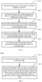
- FIG. 2 schematically shows a flowchart of a method of positioning a target object according to an embodiment of the present disclosure.
- the method may include the following operations S210 to S250.
- Three-dimensional volume data may be a three-dimensional uniformly distributed data set, that is, a structural data set composed of three-dimensional meshes.
- the first three-dimensional volume data of the checked baggage may be acquired through a variety of detection methods, such as the above-mentioned computed tomography, X-ray detection technology, etc., which will not be limited here.
- a projected image of the checked baggage in a direction is generated based on the first three-dimensional volume data.
- a direction may be any direction, and the direction may be selected without any limit.
- the projected image may be a DR (Digital Radiography) image.
- second three-dimensional volume data is segmented from the first three-dimensional volume data based on the projected image.
- At least one envelope region for at least one object in the checked baggage is determined based on the second three-dimensional volume data.
- an envelope region of the target object is determined from the determined at least one envelope region.
- the method of positioning the target object may include performing only a projection in a direction based on the first three-dimensional volume data of the checked baggage, and segmenting second three-dimensional volume data of some regions from the first three-dimensional volume data of the checked baggage based on the projected image, so that a positioning range of the target object may be reduced. Furthermore, the envelope region of each of the at least one object contained in the checked baggage is determined based on the second three-dimensional volume data, so as to determine the envelope region of the target object from the at least one envelope region.
- a reduction in the positioning range may simplify a positioning process of the target object, and improve an efficiency and an accuracy of target object positioning.
- FIG. 3 schematically shows an example flowchart of a method of positioning a target object according to another embodiment of the present disclosure, which is used to illustrate an exemplary implementation process of the above-mentioned operation S230.
- the above-mentioned process of segmenting second three-dimensional volume data from the first three-dimensional volume data based on the projected image may include operations S231 to S232.
- the above-mentioned process of forming a two-dimensional effective region in the projected image may include: acquiring a size parameter for a predetermined shape; and generating, based on a first trigger operation for a designated point in the projected image, the two-dimensional effective region of the predetermined shape centered on the designated point and conforming to the size parameter.
- FIG. 4A schematically shows an example diagram of a two-dimensional effective region according to an embodiment of the present disclosure.
- the first trigger operation may be a click operation.
- the projected image 400 is displayed. It may be understood that in the example shown in FIG. 4 , the first direction is perpendicular to a paper surface.
- the user may click any point in the region as a designated point.
- the predetermined shape may be a circle, and the size parameter for the predetermined shape is a radius of the circle.
- the predetermined shape may be any shape, such as a rectangle, a triangle, an ellipse, etc.
- the size parameter for the predetermined shape may include: a length and a width of the rectangle, a side length of the triangle, a major axis and a minor axis of the ellipse, etc., which will not be limited here.
- the above-mentioned process of forming the two-dimensional effective region in the projected image may also include: forming, based on a user's operation of drawing a closed track in the projected image, a two-dimensional effective region with the closed track as a boundary in the projected image.
- the above-mentioned process of acquiring the size parameter for the predetermined shape may use a pre-configured size parameter, or may be calculated according to actual detection data.
- the size parameter for the predetermined shape pre-configured may be acquired from a configuration table stored in an electronic device.
- the configuration table records the following information: a predetermined shape is a circle, a radius is x pixels, and x is a positive integer; or a predetermined shape is a rectangle, a length is y pixels, a width is z pixels, and both y and z are positive integers; etc.
- the size parameter for the predetermined shape may be determined according to a size parameter for the projected image, so that the size parameter for the predetermined shape is in a predetermined proportion to the size parameter for the projected image.
- a projected image of the checked baggage in the first direction has a size of 1024 x 1024 pixels.
- a predetermined ratio between a radius of the circle and a side length of the projected image is set to be 1/10, and it is estimated that the radius of the circle is 102 pixels.
- a predetermined ratio between a side length of the rectangle and a side length of the projected image is set to be 1/10, and it is estimated that a length and a width of the rectangle are both 102 pixels.
- the predetermined ratio represents a ratio between an area of the predetermined shape and an area of the projected image
- the area of the predetermined shape may be calculated according to the predetermined ratio and the area of the projected area, and then the size parameter for the predetermined shape may be calculated.
- the two-dimensional effective region is extended in the direction to form a cylindrical three-dimensional region with the two-dimensional effective region as a cross section, and three-dimensional volume data for the cylindrical three-dimensional region is determined as the second three-dimensional volume data.
- An extension direction of the two-dimensional effective region is consistent with a projection direction (the first direction, following the example above) of the projected image of the checked baggage, which may also be called a depth direction of the projected image.
- FIG. 4B schematically shows an example diagram of a cylindrical three-dimensional region according to an embodiment of the present disclosure.
- the two-dimensional effective region 401 is extended in the first direction to form a cylindrical three-dimensional region 402 with the two-dimensional effective region 401 as a cross section.
- the cylindrical three-dimensional region 402 formed is cylindrical.
- the cylindrical three-dimensional region 402 formed is a quadrangular.
- a cylindrical three-dimensional region formed based on a two-dimensional effective region of another predetermined shape is also set in the same way, which will not be repeated here.
- three-dimensional volume data for the cylindrical three-dimensional region 402 may be used as the second three-dimensional volume data segmented from the first three-dimensional volume data.
- the above-mentioned two-dimensional effective region is formed according to the user's first trigger operation for the projected image, which indicates that an actual position of the target object is desired to be in a depth direction of the two-dimensional effective region. Therefore, if the two-dimensional effective region is extended in the depth direction, the cylindrical three-dimensional region formed may contain the region where the target object is located, and the region where the target object is located may not be deleted by mistake while reducing a positioning range.
- the second three-dimensional volume data for the cylindrical three-dimensional region is used to determine an envelope region of at least one object in the checked baggage, which will be described in detail below.
- FIG. 5 schematically shows an example flowchart of a method of positioning a target object according to another embodiment of the present disclosure, which is used to illustrate an implementation process of the method of positioning the target object, and is not intended to limit the present disclosure.
- the method of positioning the target object may include operations S501 to S514.
- the three-dimensional volume data of the checked baggage may be called first three-dimensional volume data, so as to distinguish from the segmented second three-dimensional volume data.
- the first three-dimensional volume data may be loaded into a program product executing the above-mentioned method of positioning the target object.
- a projected image of the checked baggage in a direction (e.g. the first direction) is generated.
- a two-dimensional effective region centered on a designated point is formed based on a user's first trigger operation for the designated point on the projected image.
- the embodiment of forming the two-dimensional effective region has been illustrated above, and will not be repeated here.
- a cylindrical three-dimensional region is formed based on the two-dimensional effective region.
- second three-dimensional volume data for the cylindrical three-dimensional region is segmented from the first three-dimensional volume data.
- At least one envelope region for at least one object in the checked baggage is determined based on the second three-dimensional volume data.
- the second three-dimensional volume data is three-dimensional volume data segmenting from the first three-dimensional volume data of the checked baggage and corresponding to the above-mentioned cylindrical three-dimensional region. Therefore, the at least one object determined according to a specific distribution of the second three-dimensional volume data in operation S506 refers to at least one object, in the checked baggage, whose projected image in the first direction is located in the above-mentioned cylindrical three-dimensional region.
- the above-mentioned process of determining at least one envelope region for at least one object in the checked baggage based on the second three-dimensional volume data may include: segmenting, from the second three-dimensional volume data, at least one set of three-dimensional volume data conforming to a predetermined image feature by using an image recognition algorithm; and determining the at least one envelope region according to the at least one set of three-dimensional volume data.
- the envelope region of each object may be recognized and segmented by using various image recognition algorithms.
- the present disclosure does not limit the image recognition algorithm. For example, a background region in the second three-dimensional volume data may be filtered through a ray transmission volume rendering method, and the envelope region of each object may be retained and segmented.
- an envelope region of an object 1, an envelope region of an object 2, ..., and an envelope region of an object N shown on the right side of FIG. 4B may be segmented according to the second three-dimensional volume data corresponding to the cylindrical three-dimensional region on the left side of FIG. 4B .
- N is an integer greater than 2.
- the determined at least one envelope region is ranked according to a predetermined rule, so as to acquire a display sequence.
- the above-mentioned predetermined rule may be, for example, ranking in an order of priorities being decreased.
- the above-mentioned process of calculating a priority of each of the at least one envelope region may include: for each of the at least one envelope region, acquiring an attribute parameter of the envelope region; and calculating the priority of the envelope region according to the attribute parameter of the envelope region.
- the above-mentioned acquiring an attribute parameter of the envelope region includes at least one of: calculating a volume of the envelope region according to three-dimensional volume data of the envelope region; calculating a density of the envelope region according to the three-dimensional volume data of the envelope region, for example, calculating the density of the envelope region according to a pixel value distribution of the envelope region; and calculating a position coordinate of the envelope region in the above-mentioned projected image according to the three-dimensional volume data of the envelope region.
- the volume of the envelop region may reflect a size and shape of an enveloped object.
- the density of the envelop region may reflect a density of the enveloped object, thereby reflecting a material of the object.
- a distance between a centroid and a designated point of the enveloped object in the envelope region on the projected image may be calculated according to the position coordinate of the envelope region in the above-mentioned projected image.
- One or more of the above-mentioned attribute parameters may represent an attribute feature of an object targeted by the envelope region.
- the above-mentioned process of calculating a priority of the envelope region for an envelope region according to the attribute parameter of the envelope region may include: comparing an attribute feature of the object 1 with an attribute feature of a desired target object by taking the envelope region of the object 1 as an example.
- the attribute feature of the object may be expressed in a vector form, and a similarity between the attribute feature of the object 1 and the attribute feature of the desired target object may be calculated to represent a level of similarity between the object 1 and the desired target object. For example, a higher priority is set to an envelope region of an object which has a higher level of similarity with the target object.
- the envelope regions in the above-mentioned display sequence are sequentially displayed starting from a first envelope region in the display sequence.
- a first envelope region in the display sequence For example, there are N envelope regions in a display sequence, and an i-th envelope region in the display sequence is displayed.
- i is an integer greater than or equal to 1 and less than or equal to N, an initial value of i is 1, and i increases by 1 each time the display is switched.
- a projected image of the i-th envelope region in a second direction may be displayed.
- the second direction may be the same as the first direction or different from the first direction, which will not be limited here.
- projected images of the i-th envelope region in a plurality of directions may be displayed, so that the user may identify an object targeted by the i-th envelope region more quickly and accurately.
- the above-mentioned process of sequentially displaying the envelope regions in the display sequence is a process of sequentially displaying the envelope regions according to the priorities, such that one envelope region in the display sequence is displayed after another envelope region in the display sequence is displayed, wherein the another envelope region in the display sequence has a higher priority than a priority of the one envelope region in the display sequence.
- the higher the priority is, the closer the object targeted by the envelope region is to the desired target object, so such display order may enable the user to quickly identify the envelope region of the target object from the display sequence.
- operation S509 whether a user's second trigger operation for the i-th envelope region is received is determined. In a case that the user's second trigger operation for the i-th envelope region is received, operation S512 is performed. In a case that the user's second trigger operation for the i-th envelope region is not received, operation S510 is performed.
- operation S510 whether a user's third trigger operation for the i-th envelope region is received is determined. In a case that the user's third trigger operation for the i-th envelope region is received, the display is switched, i is increased by 1, and the process returns to operation S508. In a case that the user's third trigger operation for the i-th envelope region is not received, operation S511 is performed.
- three-dimensional volume data of the i-th envelope region in association with the label are added and stored into a predetermined storage region.
- the content of the label may be, for example, a predetermined identifier or identification information, so as to indicate that the three-dimensional volume data stored in associated with the label is three-dimensional volume data of the envelope region of the target obj ect.
- the operation S514 stores the three-dimensional volume data of the determined target object in association with the label, which is convenient for a subsequent use.
- the stored content may be subsequently used as sample data for training an image processing model, etc., and relevant sample data of various target objects may be gradually accumulated in a security inspection process, so that an image processing model with a better performance may be obtained by training.
- the above-mentioned second trigger operation, third trigger operation and fourth trigger operation may be preset as required.
- a first control and a second control are displayed in association.
- the user clicks the first control it is determined that the first trigger operation is performed on the i-th envelope region.
- the second control it is determined that the second trigger operation is performed on the i-th envelope region.
- a single click operation on the i-th envelope region is the first trigger operation
- a double click operation on the i-th envelope region is the second trigger operation.
- clicking a preset number of times continuously in a short preset duration may be used as the fourth trigger operation.
- FIG. 6 schematically shows a block diagram of an apparatus of positioning a target object according to an embodiment of the present disclosure.
- an apparatus 600 of positioning a target object may include: an acquisition module 610, a projection module 620, a segmentation module 630, a determination module 640, and a positioning module 650.
- the acquisition module 610 is used to acquire first three-dimensional volume data of a checked baggage.
- the projection module 620 is used to generate a projected image of the checked baggage in a direction based on the first three-dimensional volume data.
- the segmentation module 630 is used to segment second three-dimensional volume data from the first three-dimensional volume data based on the projected image.
- the determination module 640 is used to determine at least one envelope region for at least one object in the checked baggage based on the second three-dimensional volume data.
- the positioning module 650 is used to determine an envelope region of the target object from the determined at least one envelope region.
- FIG. 7 schematically shows a block diagram of an electronic device according to an embodiment of the present disclosure for implementing the method described above.
- the device shown in FIG. 7 is only an example, and is not intended to limit the function and scope of use of embodiments of the present disclosure.
- a device 700 includes a processor 701, which may perform various appropriate actions and processes according to a program stored in a read only memory (ROM) 702 or a program loaded from a storage portion 708 into a random access memory (RAM) 703.
- the processor 701 may include, for example, a general-purpose microprocessor (such as a CPU), an instruction set processor and/or a related chipset and/or a dedicated-purpose microprocessor (such as an application specific integrated circuit (ASIC)), etc.
- the processor 701 may also include an on-board memory for caching purposes.
- the processor 701 may include a single processing unit or a plurality of processing units for performing different actions of a method flow according to embodiments of the present disclosure.
- the processor 701 performs various operations of the method flow according to embodiments of the present disclosure by executing programs in the ROM 702 and/or RAM 703. It should be noted that the programs may also be stored in one or more memories other than the ROM 702 and RAM 703. The processor 701 may also perform various operations of the method flow according to embodiments of the present disclosure by executing the programs stored in the one or more memories.
- the device 700 may also include an input/output (I/O) interface 705, which is also connected to the bus 704.
- the device 700 may also include one or more of the following components connected to the I/O interface 705: an input portion 706 including a keyboard, a mouse, etc.; an output portion 707 such as a cathode ray tube (CRT), a liquid crystal display (LCD), etc., and a loudspeaker, etc.; a storage portion 708 including a hard disk, etc.; and a communication portion 709 including a network interface card such as a LAN card, a modem, etc.. The communication portion 709 performs communication processing via a network such as the internet.
- a drive 710 is also connected to the I/O interface 705 as required.
- a removable medium 711 such as a magnetic disk, optical disk, magneto-optical disk, semiconductor memory, etc., is installed on the drive 710 as required, so that computer programs read therefrom may be installed into the storage portion 708 as required.
- the method flow according to embodiments of the present disclosure may be implemented as a computer software program.
- embodiments of the present disclosure include a computer program product, which includes a computer program loaded on a computer-readable storage medium, and the computer program includes a program code for performing the method shown in the flowchart.
- the computer program may be downloaded and installed from the network through the communication portion 709, and/or installed from the removable media 711.
- the processor 701 When the computer program is executed by the processor 701, the above-mentioned functions defined in the system of embodiments of the present disclosure are performed.
- the system, device, apparatus, module, unit and the like as described above may be achieved by a computer program module.
- the above-mentioned electronic device may be used to achieve the method of positioning the target object according to embodiments of the present disclosure.
- the present disclosure further provides a computer-readable storage medium, which may be included in the device/apparatus/system described in the above-mentioned embodiment; the computer-readable storage medium may also exist alone without being assembled into the device/apparatus/system.
- the above-mentioned computer-readable storage medium carries one or more programs. The one or more programs, when executed, implement the method according to embodiments of the present disclosure.
- each block in the flowchart or block diagram may represent a module, program segment, or a portion of a code, and the above-mentioned module, program segment, or portion of the code contains one or more executable instructions for implementing a specified logical function.
- functions marked in the block may also occur in a different order from that marked in the drawings. For example, two consecutive blocks may actually be executed substantially in parallel, or they may sometimes be executed in a reverse order, which may depend on the functions involved.
- each block in the block diagram or flowchart, and a combination of the blocks in the block diagram or flowchart may be implemented with a dedicated-purpose hardware based system that performs a specified function or operation, or may be implemented with a combination of a dedicated-purpose hardware and computer instructions.
Landscapes
- Engineering & Computer Science (AREA)
- Physics & Mathematics (AREA)
- Computer Vision & Pattern Recognition (AREA)
- General Physics & Mathematics (AREA)
- Theoretical Computer Science (AREA)
- Quality & Reliability (AREA)
- Geometry (AREA)
- Analysing Materials By The Use Of Radiation (AREA)
- Image Analysis (AREA)
Abstract
Description
- This application claims priority to
Chinese Patent Application No. 202010395321.1, filed on May 11, 2020 - Embodiments of the present disclosure relate to a radiation imaging, and in particular, to a method and an apparatus of positioning a target object, a device, a medium and a program product.
- When a security check is conducted on a checked baggage, it is necessary to determine whether a target object exists in the checked baggage, and the target object is positioned when the target object exists in the checked baggage. In general, a mutual occlusion between objects in the checked baggage may bring many obstacles to a recognition and positioning of the target object, which may be time-consuming and make a user's operation process more complicated.
- According to embodiments of the present disclosure, a method and an apparatus of positioning a target object, a device, a medium and a program product are provided.
- In one aspect of the present disclosure, a method of positioning a target object is provided, including: acquiring first three-dimensional volume data of a checked baggage; generating a projected image of the checked baggage in a direction based on the first three-dimensional volume data; segmenting second three-dimensional volume data from the first three-dimensional volume data based on the projected image; determining at least one envelope region for at least one object in the checked baggage based on the second three-dimensional volume data; and determining an envelope region of the target object from the determined at least one envelope region.
- According to embodiments of the present disclosure, the above-mentioned segmenting second three-dimensional volume data from the first three-dimensional volume data based on the projected image includes: forming a two-dimensional effective region in the projected image; extending the two-dimensional effective region in the direction to form a cylindrical three-dimensional region with the two-dimensional effective region as a cross section; and determining three-dimensional volume data for the cylindrical three-dimensional region as the second three-dimensional volume data.
- According to embodiments of the present disclosure, the above-mentioned forming a two-dimensional effective region in the projected image includes: acquiring a size parameter for a predetermined shape; and generating, based on a first trigger operation for a designated point in the projected image, the two-dimensional effective region of the predetermined shape centered on the designated point and conforming to the size parameter.
- According to embodiments of the present disclosure, the above-mentioned acquiring a size parameter for a predetermined shape includes: acquiring the size parameter for the predetermined shape pre-configured in a configuration table.
- According to embodiments of the present disclosure, the above-mentioned acquiring a size parameter for a predetermined shape includes: determining the size parameter for the predetermined shape according to a size parameter for the projected image, so that the size parameter for the predetermined shape is in a predetermined proportion to the size parameter for the projected image.
- According to embodiments of the present disclosure, the above-mentioned determining at least one envelope region for at least one object in the checked baggage based on the second three-dimensional volume data includes: segmenting, from the second three-dimensional volume data, at least one set of three-dimensional volume data conforming to a predetermined image feature by using an image recognition algorithm; and determining the at least one envelope region according to the at least one set of three-dimensional volume data.
- According to embodiments of the present disclosure, the above-mentioned determining an envelope region of the target object from the at least one envelope region includes: calculating a priority of each of the at least one envelope region; sequentially displaying the at least one envelope region in an order of the calculated priorities being decreased; and determining an envelope region in the at least one envelope region as the envelope region of the target object based on a second trigger operation for the envelope region in the at least one envelope region.
- According to embodiments of the present disclosure, the above-mentioned calculating a priority of each of the at least one envelope region includes: for each of the at least one envelope region, acquiring an attribute parameter of the envelope region; and calculating the priority of the envelope region according to the attribute parameter.
- According to embodiments of the present disclosure, the above-mentioned acquiring an attribute parameter of the envelope region includes at least one of: calculating a volume of the envelope region according to three-dimensional volume data of the envelope region; calculating a density of the envelope region according to the three-dimensional volume data of the envelope region; and calculating a position coordinate of the envelope region in the projected image according to the three-dimensional volume data of the envelope region.
- According to embodiments of the present disclosure, the above-mentioned sequentially displaying the at least one envelope region in an order of the priorities being decreased includes: ranking the at least one envelope region according to the order of the priorities being decreased, so as to obtain a display sequence; displaying starting from a first envelope region in the display sequence; and when an image of an envelope region in the display sequence is displayed, switching, based on a third trigger operation for the envelope region in the display sequence, to display a posterior envelope region of the envelope region in the display sequence; and switching, based on a fourth trigger operation for the envelope region in the display sequence, to display the first envelope region displayed in the display sequence.
- According to embodiments of the present disclosure, the above-mentioned method further includes: after determining the envelope region in the at least one envelope region as the envelope region of the target object, adding a label to the envelope region; and adding and storing three-dimensional volume data of the envelope region in association with the label into a predetermined storage region.
- According to embodiments of the present disclosure, the above-mentioned acquiring first three-dimensional volume data of a checked baggage includes: acquiring the first three-dimensional volume data of the checked baggage by using a computed tomography device.
- In another aspect of the present disclosure, an apparatus of positioning a target object is provided, including: an acquisition module, a projection module, a segmentation module, a determination module and a positioning module. The acquisition module is configured to acquire first three-dimensional volume data of a checked baggage. The projection module is configured to generate a projected image of the checked baggage in a direction based on the first three-dimensional volume data. The segmentation module is configured to segment second three-dimensional volume data from the first three-dimensional volume data based on the projected image. The determination module is configured to determine at least one envelope region for at least one object in the checked baggage based on the second three-dimensional volume data. The positioning module is configured to determine an envelope region of the target object from the determined at least one envelope region.
- In another aspect of the present disclosure, an electronic device is provided, including a memory and at least one processor. The memory is configured to store instructions. The at least one processor executes the instructions stored in the memory, so as to implement the method as described in any of above-mentioned embodiments.
- In another aspect of the present disclosure, a computer-readable storage medium having computer instructions stored thereon is provided, and the computer instructions, when executed by a processor, implement the method as described in any of above-mentioned embodiments.
- In another aspect of the present disclosure, a computer program product including executable instructions is provided, and the executable instructions, when executed by a processor, implement the method as described in any of above-mentioned embodiments.
- Using the solutions of the above-mentioned embodiments of the present disclosure, based on the first three-dimensional volume data of the checked baggage, a projection may be performed in a direction only, and the second three-dimensional volume data of some regions may be segmented from the first three-dimensional volume data of the checked baggage according to the projected image, which may greatly reduce a positioning range of the target object. Furthermore, the envelope region of each of the at least one object contained in the checked baggage is determined based on the second three-dimensional volume data, so as to determine the envelope region of the target object from the at least one envelope region. In the above-mentioned process, it is not necessary to change a viewing angle for multiple times to pick up a region where the target object is located, and it is not necessary to consider whether other objects block the target object in any of the above-mentioned directions. In addition, a reduction in the positioning range may simplify a positioning process of the target object, and improve an efficiency and an accuracy of target object positioning.
- In order to better understand embodiments of the present disclosure, embodiments of the present disclosure will be described in detail according to the following accompanying drawings:
-
FIG. 1 schematically shows an application scenario of a method and an apparatus of positioning a target object according to an embodiment of the present disclosure; -
FIG. 2 schematically shows a flowchart of a method of positioning a target object according to an embodiment of the present disclosure; -
FIG. 3 schematically shows an example flowchart of a method of positioning a target object according to another embodiment of the present disclosure; -
FIG. 4A schematically shows an example diagram of a two-dimensional effective region according to an embodiment of the present disclosure; -
FIG. 4B schematically shows an example diagram of a cylindrical three-dimensional region according to an embodiment of the present disclosure; -
FIG. 5 schematically shows an example flowchart of a method of positioning a target object according to another embodiment of the present disclosure; -
FIG. 6 schematically shows a block diagram of an apparatus of positioning a target object according to an embodiment of the present disclosure; and -
FIG. 7 schematically shows a block diagram of an electronic device according to an embodiment of the present disclosure. - Specific embodiments of the present disclosure will be described in detail below. It should be noted that embodiments described here are for illustrative purposes only and are not intended to limit embodiments of the present disclosure. In the following descriptions, in order to provide a thorough understanding of embodiments of the present disclosure, a large number of specific details are set forth. However, it is obvious to those skilled in the art that: it is not necessary to implement embodiments of the present disclosure with the specific details. In other examples, well-known structures, materials, or methods are not specifically described to avoid confusion with embodiments of the present disclosure.
- Throughout the specification, a reference to "an embodiment", "embodiments", "an example" or "examples" means that: specific features, structures or characteristics described in combination with the embodiment(s) or example(s) are included in at least one embodiment of the present disclosure. Therefore, phrases "in an embodiment", "in embodiments", "an example" or "examples" present throughout the specification do not necessarily refer to the same embodiment or example. In addition, the specific features, structures, or characteristics may be combined in one or more embodiments or examples in any appropriate combination and/or sub-combination. In addition, those skilled in the art should understand that a term "and/or" used herein includes any and all combinations of one or more related listed items.
- Embodiments of the present disclosure provide a method and an apparatus of positioning a target object, a device, a medium and a program product. The method of positioning the target object may include an acquisition process, a projection process, a segmentation process, a determination process and a positioning process. In the acquisition process, first three-dimensional volume data of a checked baggage is acquired. Then, the projection process is performed, in which a projected image of the checked baggage in a direction is generated based on the first three-dimensional volume data. In the segmentation process, second three-dimensional volume data is segmented from the first three-dimensional volume data based on the projected image. In the determination process, at least one envelope region for at least one object in the checked baggage is determined based on the second three-dimensional volume data. Then, the positioning process is performed, in which an envelope region of the target object is determined from the determined at least one envelope region.
-
FIG. 1 schematically shows an application scenario of a method and an apparatus of positioning a target object according to an embodiment of the present disclosure. It should be noted thatFIG. 1 is only an example of a scenario in which embodiments of the present disclosure may be applied so as to help those skilled in the art understand the technical contents of the present disclosure, but it does not mean that embodiments of the present disclosure may not be applied to other devices, systems, environments or scenarios. - As shown in
FIG. 1 , the application scenario exemplarily shows a structural diagram of anelectronic device 100. In the example, theelectronic device 100 is a CT (Computed Tomography) device. In other examples, theelectronic device 100 may be a single energy X-ray testing device, a dual energy X-ray testing device, etc. which will not be limited here. According to embodiments of the present disclosure, theCT device 100 may include anX-ray source 10, amechanical motion device 50, a detector and adata acquisition system 20, and a control anddata processing device 60. TheCT device 100 is used to perform CT scanning and data processing on a checkedobject 40, such as a checked baggage, so as to recognize and locate a target object (such as dangerous goods, illegal goods, etc.) in the checked baggage. - The
X-ray source 10 may be, for example, an X-ray machine, and an appropriate focus size of the X-ray machine may be selected according to an imaging resolution. In other embodiments, an X-ray beam may be generated by using a linear accelerator or the like instead of using the X-ray machine. - The
mechanical motion device 50 includes a stage, a rack, a control system, etc. The stage may be translated to adjust a position of a rotation center, and the rack may be translated to align the X-ray source (X-ray machine) 10, the detector and the rotation center. The embodiment is described according to a circular scanning track or a spiral track of rotating the stage and fixing the rack. Since a movement of the stage and the rack belongs to a relative movement, the method of the embodiment may also be achieved by a way that the stage is stationary and the rack is rotated. - The detector and the
data acquisition system 20 include an X-ray detector, a data acquisition circuit, etc. The X-ray detector may use a solid detector, a gas detector or other detectors. However, embodiments of the present disclosure are not limited to this. The data acquisition circuit includes a readout circuit, an acquisition trigger circuit and a data transmission circuit, etc. - The control and
data processing device 60 includes, for example, a computer device equipped with a control program and a data processing program. The control anddata processing device 60 may be responsible for controlling an operation process of the CT device, including a mechanical translation, a mechanical rotation, an electrical control, a safety interlock control, etc., and may also process collected data. - It should be noted that the method of positioning the target object provided by embodiments of the present disclosure may generally be executed by the control and
data processing device 60. Accordingly, the apparatus of positioning the target object provided by embodiments of the present disclosure may be provided in the control anddata processing device 60. Alternatively, the method of positioning the target object provided by embodiments of the present disclosure may also be executed by a server or a server cluster that is different from the control anddata processing device 60 and capable of communicating with the control anddata processing device 60. Accordingly, the apparatus of positioning the target object provided by embodiments of the present disclosure may also be provided in the server or the server cluster that is different from the control anddata processing device 60 and capable of communicating with the control anddata processing device 60. - Based on the above-mentioned application scenarios, it is desired to determine whether a target object exists in the checked baggage when a security check is conducted on the checked baggage, and the target object is positioned when the target object exists in the checked baggage. In one processing mode, a transparent region in the three-dimensional volume data of the checked baggage is removed by a volume rendering method such as ray casting, the region where the target object is located is selected for multiple times from a plurality of perspectives within a transmission range of different rays, and a bounding box tightly enveloping a suspected object is finally acquired, so as to eliminate an influence of other surrounding regions. Considering that objects in the checked baggage usually overlap each other, a plurality of objects may overlap in a depth direction of any angle of view, so that a region where an object of interest is located may be blocked. During the positioning process, a region where another object overlapping the target object may be selected by mistake, which may bring more obstacles to a correct picking of the region where the target object is located. In order to correctly locate the target object, more times of view angle adjustment may be required, which may be time-consuming and make a user's operation process more complicated, so that an accurate and efficient positioning process may not be achieved.
- According to embodiments of the present disclosure, a method of positioning a target object is provided, which may reduce an impact on target object positioning caused by a mutual occlusion of objects in the checked baggage, simplify the user's operation process, and improve an efficiency and an accuracy of the target object positioning. The method will be exemplarily described below through the following drawings. It should be noted that the serial number of each operation in the following method is only used as a representation of the operation for the ease of description, and should not be considered as an execution order of each operation. Unless explicitly indicated, the method does not need to be executed exactly in the order shown.
-
FIG. 2 schematically shows a flowchart of a method of positioning a target object according to an embodiment of the present disclosure. - As shown in
FIG. 2 , the method may include the following operations S210 to S250. - In operation S210, first three-dimensional volume data of a checked baggage is acquired.
- Three-dimensional volume data may be a three-dimensional uniformly distributed data set, that is, a structural data set composed of three-dimensional meshes. The first three-dimensional volume data of the checked baggage may be acquired through a variety of detection methods, such as the above-mentioned computed tomography, X-ray detection technology, etc., which will not be limited here.
- In operation S220, a projected image of the checked baggage in a direction is generated based on the first three-dimensional volume data.
- The above-mentioned "a direction" may be any direction, and the direction may be selected without any limit. As an example, the projected image may be a DR (Digital Radiography) image.
- In operation S230, second three-dimensional volume data is segmented from the first three-dimensional volume data based on the projected image.
- In operation S240, at least one envelope region for at least one object in the checked baggage is determined based on the second three-dimensional volume data.
- In operation S250, an envelope region of the target object is determined from the determined at least one envelope region.
- Those skilled in the art may understand that the method of positioning the target object according to embodiments of the present disclosure may include performing only a projection in a direction based on the first three-dimensional volume data of the checked baggage, and segmenting second three-dimensional volume data of some regions from the first three-dimensional volume data of the checked baggage based on the projected image, so that a positioning range of the target object may be reduced. Furthermore, the envelope region of each of the at least one object contained in the checked baggage is determined based on the second three-dimensional volume data, so as to determine the envelope region of the target object from the at least one envelope region. In the above-mentioned process, it is not necessary to change a viewing angle for multiple times to pick up a region where the target object is located, and it is not necessary to consider whether other objects block the target object in the above-mentioned direction. In addition, a reduction in the positioning range may simplify a positioning process of the target object, and improve an efficiency and an accuracy of target object positioning.
-
FIG. 3 schematically shows an example flowchart of a method of positioning a target object according to another embodiment of the present disclosure, which is used to illustrate an exemplary implementation process of the above-mentioned operation S230. - As shown in
FIG. 3 , the above-mentioned process of segmenting second three-dimensional volume data from the first three-dimensional volume data based on the projected image may include operations S231 to S232. - In operation S231, a two-dimensional effective region is formed in the above-mentioned projected image.
- As an example, according to embodiments of the present disclosure, the above-mentioned process of forming a two-dimensional effective region in the projected image may include: acquiring a size parameter for a predetermined shape; and generating, based on a first trigger operation for a designated point in the projected image, the two-dimensional effective region of the predetermined shape centered on the designated point and conforming to the size parameter.
-
FIG. 4A schematically shows an example diagram of a two-dimensional effective region according to an embodiment of the present disclosure. As shown inFIG. 4A , for example, the first trigger operation may be a click operation. After a projectedimage 400 of the checked baggage in a direction (e.g. a first direction) is generated, the projectedimage 400 is displayed. It may be understood that in the example shown inFIG. 4 , the first direction is perpendicular to a paper surface. When a user thinks that a certain region of the projected image is suspected to be the target object, the user may click any point in the region as a designated point. In response to a user's click operation on a designated point A on the projectedimage 400, a two-dimensionaleffective region 401 of the predetermined shape centered on the designated point A and conforming to the size parameter is generated. In the example, the predetermined shape may be a circle, and the size parameter for the predetermined shape is a radius of the circle. In other examples, the predetermined shape may be any shape, such as a rectangle, a triangle, an ellipse, etc. Accordingly, the size parameter for the predetermined shape may include: a length and a width of the rectangle, a side length of the triangle, a major axis and a minor axis of the ellipse, etc., which will not be limited here. - In another embodiment of the present disclosure, the above-mentioned process of forming the two-dimensional effective region in the projected image may also include: forming, based on a user's operation of drawing a closed track in the projected image, a two-dimensional effective region with the closed track as a boundary in the projected image.
- According to embodiments of the present disclosure, the above-mentioned process of acquiring the size parameter for the predetermined shape may use a pre-configured size parameter, or may be calculated according to actual detection data. As an example, in one case, the size parameter for the predetermined shape pre-configured may be acquired from a configuration table stored in an electronic device. For example, the configuration table records the following information: a predetermined shape is a circle, a radius is x pixels, and x is a positive integer; or a predetermined shape is a rectangle, a length is y pixels, a width is z pixels, and both y and z are positive integers; etc. In another case, the size parameter for the predetermined shape may be determined according to a size parameter for the projected image, so that the size parameter for the predetermined shape is in a predetermined proportion to the size parameter for the projected image. For example, a projected image of the checked baggage in the first direction has a size of 1024 x 1024 pixels. A predetermined ratio between a radius of the circle and a side length of the projected image is set to be 1/10, and it is estimated that the radius of the circle is 102 pixels. Alternatively, a predetermined ratio between a side length of the rectangle and a side length of the projected image is set to be 1/10, and it is estimated that a length and a width of the rectangle are both 102 pixels. Alternatively, it may also be set that the predetermined ratio represents a ratio between an area of the predetermined shape and an area of the projected image, the area of the predetermined shape may be calculated according to the predetermined ratio and the area of the projected area, and then the size parameter for the predetermined shape may be calculated.
- Continuing to refer to
FIG. 3 , in operation S232, the two-dimensional effective region is extended in the direction to form a cylindrical three-dimensional region with the two-dimensional effective region as a cross section, and three-dimensional volume data for the cylindrical three-dimensional region is determined as the second three-dimensional volume data. - An extension direction of the two-dimensional effective region is consistent with a projection direction (the first direction, following the example above) of the projected image of the checked baggage, which may also be called a depth direction of the projected image.
-
FIG. 4B schematically shows an example diagram of a cylindrical three-dimensional region according to an embodiment of the present disclosure. As shown on a left side ofFIG. 4B , after the two-dimensionaleffective region 401 is formed, the two-dimensionaleffective region 401 is extended in the first direction to form a cylindrical three-dimensional region 402 with the two-dimensionaleffective region 401 as a cross section. In the example, since the two-dimensionaleffective region 401 is circular, the cylindrical three-dimensional region 402 formed is cylindrical. In other examples, if the two-dimensionaleffective region 401 is rectangular, the cylindrical three-dimensional region 402 formed is a quadrangular. A cylindrical three-dimensional region formed based on a two-dimensional effective region of another predetermined shape is also set in the same way, which will not be repeated here. In the first three-dimensional volume data of the checked baggage, three-dimensional volume data for the cylindrical three-dimensional region 402 may be used as the second three-dimensional volume data segmented from the first three-dimensional volume data. - The above-mentioned two-dimensional effective region is formed according to the user's first trigger operation for the projected image, which indicates that an actual position of the target object is desired to be in a depth direction of the two-dimensional effective region. Therefore, if the two-dimensional effective region is extended in the depth direction, the cylindrical three-dimensional region formed may contain the region where the target object is located, and the region where the target object is located may not be deleted by mistake while reducing a positioning range. The second three-dimensional volume data for the cylindrical three-dimensional region is used to determine an envelope region of at least one object in the checked baggage, which will be described in detail below.
-
FIG. 5 schematically shows an example flowchart of a method of positioning a target object according to another embodiment of the present disclosure, which is used to illustrate an implementation process of the method of positioning the target object, and is not intended to limit the present disclosure. - As shown in
FIG. 5 , the method of positioning the target object may include operations S501 to S514. - In operation S501, three-dimensional volume data of a checked baggage is loaded.
- The three-dimensional volume data of the checked baggage may be called first three-dimensional volume data, so as to distinguish from the segmented second three-dimensional volume data. After acquiring the first three-dimensional volume data, the first three-dimensional volume data may be loaded into a program product executing the above-mentioned method of positioning the target object.
- In operation S502, a projected image of the checked baggage in a direction (e.g. the first direction) is generated.
- In operation S503, a two-dimensional effective region centered on a designated point is formed based on a user's first trigger operation for the designated point on the projected image.
- According to embodiments of the present disclosure, the embodiment of forming the two-dimensional effective region has been illustrated above, and will not be repeated here.
- In operation S504, a cylindrical three-dimensional region is formed based on the two-dimensional effective region.
- According to embodiments of the present disclosure, the embodiment of forming the cylindrical three-dimensional region has been illustrated above, and will not be repeated here.
- In operation S505, second three-dimensional volume data for the cylindrical three-dimensional region is segmented from the first three-dimensional volume data.
- In operation S506, at least one envelope region for at least one object in the checked baggage is determined based on the second three-dimensional volume data.
- According to embodiments of the present disclosure, the second three-dimensional volume data is three-dimensional volume data segmenting from the first three-dimensional volume data of the checked baggage and corresponding to the above-mentioned cylindrical three-dimensional region. Therefore, the at least one object determined according to a specific distribution of the second three-dimensional volume data in operation S506 refers to at least one object, in the checked baggage, whose projected image in the first direction is located in the above-mentioned cylindrical three-dimensional region.
- As an example, the above-mentioned process of determining at least one envelope region for at least one object in the checked baggage based on the second three-dimensional volume data may include: segmenting, from the second three-dimensional volume data, at least one set of three-dimensional volume data conforming to a predetermined image feature by using an image recognition algorithm; and determining the at least one envelope region according to the at least one set of three-dimensional volume data. In this process, due to a difference between characteristics of three-dimensional volume data corresponding to an object and characteristics of three-dimensional volume data corresponding to a background, the envelope region of each object may be recognized and segmented by using various image recognition algorithms. The present disclosure does not limit the image recognition algorithm. For example, a background region in the second three-dimensional volume data may be filtered through a ray transmission volume rendering method, and the envelope region of each object may be retained and segmented.
- As shown in
FIG. 4B , for example, an envelope region of anobject 1, an envelope region of anobject 2, ..., and an envelope region of an object N shown on the right side ofFIG. 4B may be segmented according to the second three-dimensional volume data corresponding to the cylindrical three-dimensional region on the left side ofFIG. 4B . N is an integer greater than 2. - Continuing to refer to
FIG. 5 , in operation S507, the determined at least one envelope region is ranked according to a predetermined rule, so as to acquire a display sequence. - According to embodiments of the present disclosure, the above-mentioned predetermined rule may be, for example, ranking in an order of priorities being decreased. As an example, the above-mentioned process of calculating a priority of each of the at least one envelope region may include: for each of the at least one envelope region, acquiring an attribute parameter of the envelope region; and calculating the priority of the envelope region according to the attribute parameter of the envelope region.
- For example, the above-mentioned acquiring an attribute parameter of the envelope region includes at least one of: calculating a volume of the envelope region according to three-dimensional volume data of the envelope region; calculating a density of the envelope region according to the three-dimensional volume data of the envelope region, for example, calculating the density of the envelope region according to a pixel value distribution of the envelope region; and calculating a position coordinate of the envelope region in the above-mentioned projected image according to the three-dimensional volume data of the envelope region. The volume of the envelop region may reflect a size and shape of an enveloped object. The density of the envelop region may reflect a density of the enveloped object, thereby reflecting a material of the object. A distance between a centroid and a designated point of the enveloped object in the envelope region on the projected image may be calculated according to the position coordinate of the envelope region in the above-mentioned projected image. One or more of the above-mentioned attribute parameters may represent an attribute feature of an object targeted by the envelope region. On this basis, the above-mentioned process of calculating a priority of the envelope region for an envelope region according to the attribute parameter of the envelope region may include: comparing an attribute feature of the
object 1 with an attribute feature of a desired target object by taking the envelope region of theobject 1 as an example. For example, the attribute feature of the object may be expressed in a vector form, and a similarity between the attribute feature of theobject 1 and the attribute feature of the desired target object may be calculated to represent a level of similarity between theobject 1 and the desired target object. For example, a higher priority is set to an envelope region of an object which has a higher level of similarity with the target object. - Continuing to refer to
FIG. 5 , in operation S508, the envelope regions in the above-mentioned display sequence are sequentially displayed starting from a first envelope region in the display sequence. For example, there are N envelope regions in a display sequence, and an i-th envelope region in the display sequence is displayed. i is an integer greater than or equal to 1 and less than or equal to N, an initial value of i is 1, and i increases by 1 each time the display is switched. When i=N, the first envelope region is displayed again when the display is switched. - As an example, when the i-th envelope region is displayed, a projected image of the i-th envelope region in a second direction may be displayed. The second direction may be the same as the first direction or different from the first direction, which will not be limited here. In an example, when the i-th envelope region is displayed, projected images of the i-th envelope region in a plurality of directions may be displayed, so that the user may identify an object targeted by the i-th envelope region more quickly and accurately.
- According to embodiments of the present disclosure, if the envelope regions in the display sequence are arranged in the order of the priorities being decreased, the above-mentioned process of sequentially displaying the envelope regions in the display sequence is a process of sequentially displaying the envelope regions according to the priorities, such that one envelope region in the display sequence is displayed after another envelope region in the display sequence is displayed, wherein the another envelope region in the display sequence has a higher priority than a priority of the one envelope region in the display sequence. In the above-mentioned example, the higher the priority is, the closer the object targeted by the envelope region is to the desired target object, so such display order may enable the user to quickly identify the envelope region of the target object from the display sequence.
- Continuing to refer to
FIG. 5 , in operation S509, whether a user's second trigger operation for the i-th envelope region is received is determined. In a case that the user's second trigger operation for the i-th envelope region is received, operation S512 is performed. In a case that the user's second trigger operation for the i-th envelope region is not received, operation S510 is performed. - In operation S510, whether a user's third trigger operation for the i-th envelope region is received is determined. In a case that the user's third trigger operation for the i-th envelope region is received, the display is switched, i is increased by 1, and the process returns to operation S508. In a case that the user's third trigger operation for the i-th envelope region is not received, operation S511 is performed.
- In operation S511, whether a user's fourth trigger operation for the i-th envelope region is received is determined. In a case that user's fourth trigger operation for the i-th envelope region is received, a re-display is performed, i=1 is enabled and the process returns to operation S508. In a case that user's fourth trigger operation for the i-th envelope region is not received, the process returns to operation S508 directly and the i-th envelope region continues to be displayed.
- In operation S512, it is determined that the i-th envelope region is an envelope region of the target object.
- In operation S513, a label is added to the i-th envelope region.
- In operation S514, three-dimensional volume data of the i-th envelope region in association with the label are added and stored into a predetermined storage region. The content of the label may be, for example, a predetermined identifier or identification information, so as to indicate that the three-dimensional volume data stored in associated with the label is three-dimensional volume data of the envelope region of the target obj ect.
- The operation S514 stores the three-dimensional volume data of the determined target object in association with the label, which is convenient for a subsequent use. For example, the stored content may be subsequently used as sample data for training an image processing model, etc., and relevant sample data of various target objects may be gradually accumulated in a security inspection process, so that an image processing model with a better performance may be obtained by training.
- According to embodiments of the present disclosure, the above-mentioned second trigger operation, third trigger operation and fourth trigger operation may be preset as required. For example, when the i-th envelope region is displayed, a first control and a second control are displayed in association. When the user clicks the first control, it is determined that the first trigger operation is performed on the i-th envelope region. When the user clicks the second control, it is determined that the second trigger operation is performed on the i-th envelope region. Alternatively, a single click operation on the i-th envelope region is the first trigger operation, and a double click operation on the i-th envelope region is the second trigger operation. For another example, clicking a preset number of times continuously in a short preset duration may be used as the fourth trigger operation.
-
FIG. 6 schematically shows a block diagram of an apparatus of positioning a target object according to an embodiment of the present disclosure. - As shown in
FIG. 6 , anapparatus 600 of positioning a target object may include: anacquisition module 610, aprojection module 620, asegmentation module 630, adetermination module 640, and apositioning module 650. - The
acquisition module 610 is used to acquire first three-dimensional volume data of a checked baggage. - The
projection module 620 is used to generate a projected image of the checked baggage in a direction based on the first three-dimensional volume data. - The
segmentation module 630 is used to segment second three-dimensional volume data from the first three-dimensional volume data based on the projected image. - The
determination module 640 is used to determine at least one envelope region for at least one object in the checked baggage based on the second three-dimensional volume data. - The
positioning module 650 is used to determine an envelope region of the target object from the determined at least one envelope region. - It should be noted that the implementation mode, solved technical problems, achieved functions, and achieved technical effects of each module/unit/subunit in the embodiment of the apparatus portion are the same or similar to the implementation mode, solved technical problems, achieved functions, and achieved technical effects of each corresponding step in the embodiment of the method portion, which will not be repeated here.
-
FIG. 7 schematically shows a block diagram of an electronic device according to an embodiment of the present disclosure for implementing the method described above. The device shown inFIG. 7 is only an example, and is not intended to limit the function and scope of use of embodiments of the present disclosure. - As shown in
FIG. 7 , adevice 700 according to embodiments of the present disclosure includes aprocessor 701, which may perform various appropriate actions and processes according to a program stored in a read only memory (ROM) 702 or a program loaded from astorage portion 708 into a random access memory (RAM) 703. Theprocessor 701 may include, for example, a general-purpose microprocessor (such as a CPU), an instruction set processor and/or a related chipset and/or a dedicated-purpose microprocessor (such as an application specific integrated circuit (ASIC)), etc. Theprocessor 701 may also include an on-board memory for caching purposes. Theprocessor 701 may include a single processing unit or a plurality of processing units for performing different actions of a method flow according to embodiments of the present disclosure. - In the
RAM 703, various programs and data required for an operation of thedevice 700 are stored. Theprocessor 701, theROM 702 and theRAM 703 are connected to each other via abus 704. Theprocessor 701 performs various operations of the method flow according to embodiments of the present disclosure by executing programs in theROM 702 and/orRAM 703. It should be noted that the programs may also be stored in one or more memories other than theROM 702 andRAM 703. Theprocessor 701 may also perform various operations of the method flow according to embodiments of the present disclosure by executing the programs stored in the one or more memories. - According to embodiments of the present disclosure, the
device 700 may also include an input/output (I/O)interface 705, which is also connected to thebus 704. Thedevice 700 may also include one or more of the following components connected to the I/O interface 705: aninput portion 706 including a keyboard, a mouse, etc.; anoutput portion 707 such as a cathode ray tube (CRT), a liquid crystal display (LCD), etc., and a loudspeaker, etc.; astorage portion 708 including a hard disk, etc.; and acommunication portion 709 including a network interface card such as a LAN card, a modem, etc.. Thecommunication portion 709 performs communication processing via a network such as the internet. Adrive 710 is also connected to the I/O interface 705 as required. Aremovable medium 711, such as a magnetic disk, optical disk, magneto-optical disk, semiconductor memory, etc., is installed on thedrive 710 as required, so that computer programs read therefrom may be installed into thestorage portion 708 as required. - According to embodiments of the present disclosure, the method flow according to embodiments of the present disclosure may be implemented as a computer software program. For example, embodiments of the present disclosure include a computer program product, which includes a computer program loaded on a computer-readable storage medium, and the computer program includes a program code for performing the method shown in the flowchart. In the embodiment, the computer program may be downloaded and installed from the network through the
communication portion 709, and/or installed from theremovable media 711. When the computer program is executed by theprocessor 701, the above-mentioned functions defined in the system of embodiments of the present disclosure are performed. According to embodiments of the present disclosure, the system, device, apparatus, module, unit and the like as described above may be achieved by a computer program module. - According to embodiments of the present disclosure, the above-mentioned electronic device may be used to achieve the method of positioning the target object according to embodiments of the present disclosure.
- The present disclosure further provides a computer-readable storage medium, which may be included in the device/apparatus/system described in the above-mentioned embodiment; the computer-readable storage medium may also exist alone without being assembled into the device/apparatus/system. The above-mentioned computer-readable storage medium carries one or more programs. The one or more programs, when executed, implement the method according to embodiments of the present disclosure.
- The flowcharts and block diagrams in the accompanying drawings illustrate possible architectures, functions, and operations of systems, methods, and computer program products according to various embodiments of the present disclosure. In this regard, each block in the flowchart or block diagram may represent a module, program segment, or a portion of a code, and the above-mentioned module, program segment, or portion of the code contains one or more executable instructions for implementing a specified logical function. It should also be noted that in some alternative implementations, functions marked in the block may also occur in a different order from that marked in the drawings. For example, two consecutive blocks may actually be executed substantially in parallel, or they may sometimes be executed in a reverse order, which may depend on the functions involved. It should also be noted that each block in the block diagram or flowchart, and a combination of the blocks in the block diagram or flowchart, may be implemented with a dedicated-purpose hardware based system that performs a specified function or operation, or may be implemented with a combination of a dedicated-purpose hardware and computer instructions.
- Those skilled in the art may understand that, although the present disclosure has been shown and described with reference to specific exemplary embodiments of the present disclosure, they should understand that the present disclosure may be changed in form and detail without departing from the spirit and scope of the present disclosure defined by the appended claims and their equivalents. Therefore, the scope of the present disclosure should not be limited to the above-mentioned embodiments, but should be determined not only by the appended claims, but also by the equivalents of the appended claims.
Claims (16)
- A method of positioning a target object, comprising:acquiring first three-dimensional volume data of a checked baggage;generating a projected image of the checked baggage in a direction based on the first three-dimensional volume data;segmenting second three-dimensional volume data from the first three-dimensional volume data based on the projected image;determining at least one envelope region for at least one object in the checked baggage based on the second three-dimensional volume data; anddetermining an envelope region of the target object from the at least one envelope region.
- The method according to claim 1, wherein the segmenting second three-dimensional volume data from the first three-dimensional volume data based on the projected image comprises:forming a two-dimensional effective region in the projected image;extending the two-dimensional effective region in the direction to form a cylindrical three-dimensional region with the two-dimensional effective region as a cross section; anddetermining three-dimensional volume data for the cylindrical three-dimensional region as the second three-dimensional volume data.
- The method according to claim 2, wherein the forming a two-dimensional effective region in the projected image comprises:acquiring a size parameter for a predetermined shape; andgenerating, based on a first trigger operation for a designated point in the projected image, the two-dimensional effective region of the predetermined shape centered on the designated point and conforming to the size parameter.
- The method according to claim 3, wherein the acquiring a size parameter for a predetermined shape comprises:
acquiring the size parameter for the predetermined shape pre-configured in a configuration table. - The method according to claim 3, wherein the acquiring a size parameter for a predetermined shape comprises:
determining the size parameter for the predetermined shape according to a size parameter for the projected image, so that the size parameter for the predetermined shape is in a predetermined proportion to the size parameter for the projected image. - The method according to claim 1, wherein the determining at least one envelope region for at least one object in the checked baggage based on the second three-dimensional volume data comprises:segmenting, from the second three-dimensional volume data, at least one set of three-dimensional volume data conforming to a predetermined image feature by using an image recognition algorithm; anddetermining the at least one envelope region according to the at least one set of three-dimensional volume data.
- The method according to claim 6, wherein the determining an envelope region of the target object from the at least one envelope region comprises:calculating a priority of each of the at least one envelope region;sequentially displaying the at least one envelope region in an order of the priorities being decreased; anddetermining an envelope region in the at least one envelope region as the envelope region of the target object based on a second trigger operation for the envelope region in the at least one envelope region.
- The method according to claim 7, wherein the calculating a priority of each of the at least one envelope region comprises: for each of the at least one envelope region,acquiring an attribute parameter of the envelope region; andcalculating the priority of the envelope region according to the attribute parameter.
- The method according to claim 8, wherein the acquiring an attribute parameter of the envelope region comprises at least one of:calculating a volume of the envelope region according to three-dimensional volume data of the envelope region;calculating a density of the envelope region according to the three-dimensional volume data of the envelope region; andcalculating a position coordinate of the envelope region in the projected image according to the three-dimensional volume data of the envelope region.
- The method according to claim 7, wherein the sequentially displaying the at least one envelope region in an order of the priorities being decreased comprises:ranking the at least one envelope region according to the order of the priorities being decreased, so as to obtain a display sequence;displaying starting from a first envelope region in the display sequence; andwhen an image of an envelope region in the display sequence is displayed,switching, based on a third trigger operation for the envelope region in the display sequence, to display a posterior envelope region of the envelope region in the display sequence; andswitching, based on a fourth trigger operation for the envelope region in the display sequence, to display the first envelope region in the display sequence.
- The method according to claim 7, further comprising: after determining the envelope region in the at least one envelope region as the envelope region of the target object,adding a label to the envelope region; andadding and storing three-dimensional volume data of the envelope region in association with the label into a predetermined storage region.
- The method according to claim 1, wherein the acquiring first three-dimensional volume data of a checked baggage comprises:
acquiring the first three-dimensional volume data of the checked baggage by using a computed tomography device. - An apparatus of positioning a target object, comprising:an acquisition module configured to acquire first three-dimensional volume data of a checked baggage;a projection module configured to generate a projected image of the checked baggage in a direction based on the first three-dimensional volume data;a segmentation module configured to segment second three-dimensional volume data from the first three-dimensional volume data based on the projected image;a determination module configured to determine at least one envelope region for at least one object in the checked baggage based on the second three-dimensional volume data; anda positioning module configured to determine an envelope region of the target object from the at least one envelope region.
- An electronic device, comprising:a memory configured to store instructions;at least one processor;wherein the at least one processor executes the instructions stored in the memory, so as to implement the method according to one of claims 1 to 12.
- A computer-readable storage medium having computer instructions stored thereon, wherein the computer instructions, when executed by a processor, implement the method according to one of claims 1 to 12.
- A computer program product comprising executable instructions, wherein the executable instructions, when executed by a processor, implement the method according to one of claims 1 to 12.
Applications Claiming Priority (2)
| Application Number | Priority Date | Filing Date | Title |
|---|---|---|---|
| CN202010395321.1A CN113643360B (en) | 2020-05-11 | 2020-05-11 | Target object positioning method, device, equipment, medium and program product |
| PCT/CN2021/102460 WO2021228281A1 (en) | 2020-05-11 | 2021-06-25 | Target object positioning method and apparatus, device, medium, and program product |
Publications (3)
| Publication Number | Publication Date |
|---|---|
| EP4152254A1 true EP4152254A1 (en) | 2023-03-22 |
| EP4152254A4 EP4152254A4 (en) | 2024-07-17 |
| EP4152254B1 EP4152254B1 (en) | 2025-09-24 |
Family
ID=78415594
Family Applications (1)
| Application Number | Title | Priority Date | Filing Date |
|---|---|---|---|
| EP21803947.7A Active EP4152254B1 (en) | 2020-05-11 | 2021-06-25 | Target object positioning method and apparatus, device, medium, and program product |
Country Status (4)
| Country | Link |
|---|---|
| EP (1) | EP4152254B1 (en) |
| CN (1) | CN113643360B (en) |
| ES (1) | ES3057405T3 (en) |
| WO (1) | WO2021228281A1 (en) |
Families Citing this family (2)
| Publication number | Priority date | Publication date | Assignee | Title |
|---|---|---|---|---|
| CN114708171B (en) * | 2021-12-23 | 2025-04-01 | 中广核贝谷科技有限公司 | A three-dimensional image fusion method and device based on computer tomography |
| CN120162934B (en) * | 2024-09-20 | 2025-10-14 | 中航信移动科技股份有限公司 | Luggage stacking position determining method, equipment and storage medium based on condition degradation |
Family Cites Families (20)
| Publication number | Priority date | Publication date | Assignee | Title |
|---|---|---|---|---|
| US6088423A (en) * | 1998-06-05 | 2000-07-11 | Vivid Technologies, Inc. | Multiview x-ray based system for detecting contraband such as in baggage |
| GB2398469B (en) * | 2003-02-12 | 2005-10-26 | Canon Europa Nv | Image processing apparatus |
| EP1880331A4 (en) * | 2005-05-11 | 2011-05-04 | Optosecurity Inc | User interface for use in screening luggage, containers, parcels or people and apparatus for implementing same |
| US20090174554A1 (en) * | 2005-05-11 | 2009-07-09 | Eric Bergeron | Method and system for screening luggage items, cargo containers or persons |
| CN101882319B (en) * | 2010-06-24 | 2011-11-30 | 西北工业大学 | Cone beam CT fast reconstructing method based on minimum three-dimensional convex hull |
| JP2012161460A (en) * | 2011-02-07 | 2012-08-30 | Fujifilm Corp | Image processor, image processing method and image processing program |
| JP5132832B1 (en) * | 2011-07-11 | 2013-01-30 | キヤノン株式会社 | Measuring apparatus and information processing apparatus |
| CN103900503B (en) * | 2012-12-27 | 2016-12-28 | 清华大学 | Extract the method for shape facility, safety detection method and equipment |
| CN103903303B (en) * | 2012-12-27 | 2018-01-30 | 清华大学 | Threedimensional model creation method and equipment |
| CN103901489B (en) * | 2012-12-27 | 2017-07-21 | 清华大学 | Check method, display methods and the equipment of object |
| CN104715471B (en) * | 2014-01-03 | 2018-01-02 | 杭州海康威视数字技术股份有限公司 | Target locating method and its device |
| CN105784731B (en) * | 2014-06-25 | 2019-02-22 | 同方威视技术股份有限公司 | A method and security inspection system for locating a target in a three-dimensional CT image |
| EP3112909B1 (en) * | 2014-12-18 | 2022-04-20 | Nuctech Company Limited | Method for positioning target in three-dimensional ct image and security check ct system |
| US11436735B2 (en) * | 2015-02-11 | 2022-09-06 | Analogic Corporation | Three-dimensional object image generation |
| US10380727B2 (en) * | 2016-05-06 | 2019-08-13 | L-3 Communications Security & Detection Systems, Inc. | Systems and methods for generating projection images |
| US20180239313A1 (en) * | 2017-02-22 | 2018-08-23 | Stellar Vdc Residential, Llc | Building model with virtual capture of as built features and objective performance tracking |
| US10872409B2 (en) * | 2018-02-07 | 2020-12-22 | Analogic Corporation | Visual augmentation of regions within images |
| CN108459802B (en) * | 2018-02-28 | 2020-11-20 | 北京航星机器制造有限公司 | A touch display terminal interaction method and device |
| CN110660123B (en) * | 2018-06-29 | 2021-08-31 | 清华大学 | Three-dimensional CT image reconstruction method and device and storage medium based on neural network |
| CN109146801A (en) * | 2018-07-25 | 2019-01-04 | 深圳汇创联合自动化控制有限公司 | Create the equipment for being examined the threedimensional model of object in luggage |
-
2020
- 2020-05-11 CN CN202010395321.1A patent/CN113643360B/en active Active
-
2021
- 2021-06-25 WO PCT/CN2021/102460 patent/WO2021228281A1/en not_active Ceased
- 2021-06-25 EP EP21803947.7A patent/EP4152254B1/en active Active
- 2021-06-25 ES ES21803947T patent/ES3057405T3/en active Active
Also Published As
| Publication number | Publication date |
|---|---|
| CN113643360B (en) | 2024-12-27 |
| EP4152254A4 (en) | 2024-07-17 |
| ES3057405T3 (en) | 2026-03-02 |
| WO2021228281A1 (en) | 2021-11-18 |
| EP4152254B1 (en) | 2025-09-24 |
| CN113643360A (en) | 2021-11-12 |
Similar Documents
| Publication | Publication Date | Title |
|---|---|---|
| US9053565B2 (en) | Interactive selection of a region of interest in an image | |
| US8493389B2 (en) | 3D connected shadow mouse pointer | |
| JP4245353B2 (en) | Object order volume rendering occlusion culling | |
| EP1728216B1 (en) | Image visualization | |
| US10380735B2 (en) | Image data segmentation | |
| US10319119B2 (en) | Methods and systems for accelerated reading of a 3D medical volume | |
| CN113658284B (en) | X-ray image synthesis from CT images for training nodule detection systems | |
| RU2612572C2 (en) | Image processing system and method | |
| EP4152254B1 (en) | Target object positioning method and apparatus, device, medium, and program product | |
| US9547906B2 (en) | System and method for data driven editing of rib unfolding | |
| AU2023420138A1 (en) | Method and apparatus for separating target object in three-dimensional ct image, and security inspection ct system | |
| US9754411B2 (en) | Path proximity rendering | |
| WO2014050043A1 (en) | Image processing device, image processing method, and image processing program | |
| EP4152261A1 (en) | Target region positioning method and apparatus, device, medium, and program product | |
| EP4238055A1 (en) | Detection of spine vertebrae in image data | |
| US20230342994A1 (en) | Storage medium, image identification method, image identification device | |
| CN115330917A (en) | Data processing method, device and storage medium |
Legal Events
| Date | Code | Title | Description |
|---|---|---|---|
| STAA | Information on the status of an ep patent application or granted ep patent |
Free format text: STATUS: THE INTERNATIONAL PUBLICATION HAS BEEN MADE |
|
| PUAI | Public reference made under article 153(3) epc to a published international application that has entered the european phase |
Free format text: ORIGINAL CODE: 0009012 |
|
| STAA | Information on the status of an ep patent application or granted ep patent |
Free format text: STATUS: REQUEST FOR EXAMINATION WAS MADE |
|
| 17P | Request for examination filed |
Effective date: 20221111 |
|
| AK | Designated contracting states |
Kind code of ref document: A1 Designated state(s): AL AT BE BG CH CY CZ DE DK EE ES FI FR GB GR HR HU IE IS IT LI LT LU LV MC MK MT NL NO PL PT RO RS SE SI SK SM TR |
|
| XX | Miscellaneous (additional remarks) |
Free format text: A REQUEST FOR RESTORATION OF THE RIGHT OF PRIORITY UNDER RULE 49TER.2 PCT IS PENDING BEFORE THE EPO AS DESIGNATED OFFICE. |
|
| DAV | Request for validation of the european patent (deleted) | ||
| DAX | Request for extension of the european patent (deleted) | ||
| REG | Reference to a national code |
Ref country code: DE Ref legal event code: R079 Free format text: PREVIOUS MAIN CLASS: G06T0007110000 Ipc: G06T0007000000 Ref document number: 602021039230 Country of ref document: DE |
|
| A4 | Supplementary search report drawn up and despatched |
Effective date: 20240619 |
|
| RIC1 | Information provided on ipc code assigned before grant |
Ipc: G06T 7/62 20170101ALI20240613BHEP Ipc: G06T 7/11 20170101ALI20240613BHEP Ipc: G06T 7/00 20170101AFI20240613BHEP |
|
| GRAP | Despatch of communication of intention to grant a patent |
Free format text: ORIGINAL CODE: EPIDOSNIGR1 |
|
| STAA | Information on the status of an ep patent application or granted ep patent |
Free format text: STATUS: GRANT OF PATENT IS INTENDED |
|
| INTG | Intention to grant announced |
Effective date: 20250417 |
|
| GRAS | Grant fee paid |
Free format text: ORIGINAL CODE: EPIDOSNIGR3 |
|
| GRAA | (expected) grant |
Free format text: ORIGINAL CODE: 0009210 |
|
| STAA | Information on the status of an ep patent application or granted ep patent |
Free format text: STATUS: THE PATENT HAS BEEN GRANTED |
|
| AK | Designated contracting states |
Kind code of ref document: B1 Designated state(s): AL AT BE BG CH CY CZ DE DK EE ES FI FR GB GR HR HU IE IS IT LI LT LU LV MC MK MT NL NO PL PT RO RS SE SI SK SM TR |
|
| REG | Reference to a national code |
Ref country code: GB Ref legal event code: FG4D |
|
| XX | Miscellaneous (additional remarks) |
Free format text: A REQUEST FOR RESTORATION OF THE RIGHT OF PRIORITY UNDER RULE 49TER.2 PCT IS PENDING BEFORE THE EPO AS DESIGNATED OFFICE. |
|
| REG | Reference to a national code |
Ref country code: CH Ref legal event code: EP |
|
| REG | Reference to a national code |
Ref country code: DE Ref legal event code: R096 Ref document number: 602021039230 Country of ref document: DE |
|
| REG | Reference to a national code |
Ref country code: IE Ref legal event code: FG4D |
|
| REG | Reference to a national code |
Ref country code: CH Ref legal event code: R17 Free format text: ST27 STATUS EVENT CODE: U-0-0-R10-R17 (AS PROVIDED BY THE NATIONAL OFFICE) Effective date: 20251218 |
|
| REG | Reference to a national code |
Ref country code: NL Ref legal event code: FP |
|
| PG25 | Lapsed in a contracting state [announced via postgrant information from national office to epo] |
Ref country code: NO Free format text: LAPSE BECAUSE OF FAILURE TO SUBMIT A TRANSLATION OF THE DESCRIPTION OR TO PAY THE FEE WITHIN THE PRESCRIBED TIME-LIMIT Effective date: 20251224 |
|
| REG | Reference to a national code |
Ref country code: LT Ref legal event code: MG9D |
|
| PG25 | Lapsed in a contracting state [announced via postgrant information from national office to epo] |
Ref country code: FI Free format text: LAPSE BECAUSE OF FAILURE TO SUBMIT A TRANSLATION OF THE DESCRIPTION OR TO PAY THE FEE WITHIN THE PRESCRIBED TIME-LIMIT Effective date: 20250924 |
|
| PG25 | Lapsed in a contracting state [announced via postgrant information from national office to epo] |
Ref country code: HR Free format text: LAPSE BECAUSE OF FAILURE TO SUBMIT A TRANSLATION OF THE DESCRIPTION OR TO PAY THE FEE WITHIN THE PRESCRIBED TIME-LIMIT Effective date: 20250924 |
|
| PG25 | Lapsed in a contracting state [announced via postgrant information from national office to epo] |
Ref country code: GR Free format text: LAPSE BECAUSE OF FAILURE TO SUBMIT A TRANSLATION OF THE DESCRIPTION OR TO PAY THE FEE WITHIN THE PRESCRIBED TIME-LIMIT Effective date: 20251225 |
|
| PG25 | Lapsed in a contracting state [announced via postgrant information from national office to epo] |
Ref country code: SE Free format text: LAPSE BECAUSE OF FAILURE TO SUBMIT A TRANSLATION OF THE DESCRIPTION OR TO PAY THE FEE WITHIN THE PRESCRIBED TIME-LIMIT Effective date: 20250924 |
|
| PG25 | Lapsed in a contracting state [announced via postgrant information from national office to epo] |
Ref country code: LV Free format text: LAPSE BECAUSE OF FAILURE TO SUBMIT A TRANSLATION OF THE DESCRIPTION OR TO PAY THE FEE WITHIN THE PRESCRIBED TIME-LIMIT Effective date: 20250924 |
|
| PG25 | Lapsed in a contracting state [announced via postgrant information from national office to epo] |
Ref country code: BG Free format text: LAPSE BECAUSE OF FAILURE TO SUBMIT A TRANSLATION OF THE DESCRIPTION OR TO PAY THE FEE WITHIN THE PRESCRIBED TIME-LIMIT Effective date: 20250924 |
|
| PG25 | Lapsed in a contracting state [announced via postgrant information from national office to epo] |
Ref country code: RS Free format text: LAPSE BECAUSE OF FAILURE TO SUBMIT A TRANSLATION OF THE DESCRIPTION OR TO PAY THE FEE WITHIN THE PRESCRIBED TIME-LIMIT Effective date: 20251224 |
|
| REG | Reference to a national code |
Ref country code: ES Ref legal event code: FG2A Ref document number: 3057405 Country of ref document: ES Kind code of ref document: T3 Effective date: 20260302 |
|
| REG | Reference to a national code |
Ref country code: AT Ref legal event code: MK05 Ref document number: 1840980 Country of ref document: AT Kind code of ref document: T Effective date: 20250924 |
|
| PG25 | Lapsed in a contracting state [announced via postgrant information from national office to epo] |
Ref country code: SM Free format text: LAPSE BECAUSE OF FAILURE TO SUBMIT A TRANSLATION OF THE DESCRIPTION OR TO PAY THE FEE WITHIN THE PRESCRIBED TIME-LIMIT Effective date: 20250924 |
|
| PG25 | Lapsed in a contracting state [announced via postgrant information from national office to epo] |
Ref country code: AT Free format text: LAPSE BECAUSE OF FAILURE TO SUBMIT A TRANSLATION OF THE DESCRIPTION OR TO PAY THE FEE WITHIN THE PRESCRIBED TIME-LIMIT Effective date: 20250924 |
|
| PG25 | Lapsed in a contracting state [announced via postgrant information from national office to epo] |
Ref country code: IS Free format text: LAPSE BECAUSE OF FAILURE TO SUBMIT A TRANSLATION OF THE DESCRIPTION OR TO PAY THE FEE WITHIN THE PRESCRIBED TIME-LIMIT Effective date: 20260124 |
|
| PG25 | Lapsed in a contracting state [announced via postgrant information from national office to epo] |
Ref country code: CZ Free format text: LAPSE BECAUSE OF FAILURE TO SUBMIT A TRANSLATION OF THE DESCRIPTION OR TO PAY THE FEE WITHIN THE PRESCRIBED TIME-LIMIT Effective date: 20250924 Ref country code: PT Free format text: LAPSE BECAUSE OF FAILURE TO SUBMIT A TRANSLATION OF THE DESCRIPTION OR TO PAY THE FEE WITHIN THE PRESCRIBED TIME-LIMIT Effective date: 20260126 |
|
| PG25 | Lapsed in a contracting state [announced via postgrant information from national office to epo] |
Ref country code: PL Free format text: LAPSE BECAUSE OF FAILURE TO SUBMIT A TRANSLATION OF THE DESCRIPTION OR TO PAY THE FEE WITHIN THE PRESCRIBED TIME-LIMIT Effective date: 20250924 |
|
| PG25 | Lapsed in a contracting state [announced via postgrant information from national office to epo] |
Ref country code: EE Free format text: LAPSE BECAUSE OF FAILURE TO SUBMIT A TRANSLATION OF THE DESCRIPTION OR TO PAY THE FEE WITHIN THE PRESCRIBED TIME-LIMIT Effective date: 20250924 Ref country code: SK Free format text: LAPSE BECAUSE OF FAILURE TO SUBMIT A TRANSLATION OF THE DESCRIPTION OR TO PAY THE FEE WITHIN THE PRESCRIBED TIME-LIMIT Effective date: 20250924 |