EP4152097A1 - Extreme ultraviolet light source device - Google Patents
Extreme ultraviolet light source device Download PDFInfo
- Publication number
- EP4152097A1 EP4152097A1 EP21804523.5A EP21804523A EP4152097A1 EP 4152097 A1 EP4152097 A1 EP 4152097A1 EP 21804523 A EP21804523 A EP 21804523A EP 4152097 A1 EP4152097 A1 EP 4152097A1
- Authority
- EP
- European Patent Office
- Prior art keywords
- support structure
- wall portion
- support
- cathode
- anode
- Prior art date
- Legal status (The legal status is an assumption and is not a legal conclusion. Google has not performed a legal analysis and makes no representation as to the accuracy of the status listed.)
- Granted
Links
Images





Classifications
-
- H—ELECTRICITY
- H05—ELECTRIC TECHNIQUES NOT OTHERWISE PROVIDED FOR
- H05G—X-RAY TECHNIQUE
- H05G2/00—Apparatus or processes specially adapted for producing X-rays, not involving X-ray tubes, e.g. involving generation of a plasma
- H05G2/001—Production of X-ray radiation generated from plasma
- H05G2/003—Production of X-ray radiation generated from plasma the plasma being generated from a material in a liquid or gas state
- H05G2/0035—Production of X-ray radiation generated from plasma the plasma being generated from a material in a liquid or gas state the material containing metals as principal radiation-generating components
-
- G—PHYSICS
- G03—PHOTOGRAPHY; CINEMATOGRAPHY; ANALOGOUS TECHNIQUES USING WAVES OTHER THAN OPTICAL WAVES; ELECTROGRAPHY; HOLOGRAPHY
- G03F—PHOTOMECHANICAL PRODUCTION OF TEXTURED OR PATTERNED SURFACES, e.g. FOR PRINTING, FOR PROCESSING OF SEMICONDUCTOR DEVICES; MATERIALS THEREFOR; ORIGINALS THEREFOR; APPARATUS SPECIALLY ADAPTED THEREFOR
- G03F1/00—Originals for photomechanical production of textured or patterned surfaces, e.g., masks, photo-masks, reticles; Mask blanks or pellicles therefor; Containers specially adapted therefor; Preparation thereof
- G03F1/68—Preparation processes not covered by groups G03F1/20 - G03F1/50
- G03F1/82—Auxiliary processes, e.g. cleaning or inspecting
- G03F1/84—Inspecting
-
- G—PHYSICS
- G03—PHOTOGRAPHY; CINEMATOGRAPHY; ANALOGOUS TECHNIQUES USING WAVES OTHER THAN OPTICAL WAVES; ELECTROGRAPHY; HOLOGRAPHY
- G03F—PHOTOMECHANICAL PRODUCTION OF TEXTURED OR PATTERNED SURFACES, e.g. FOR PRINTING, FOR PROCESSING OF SEMICONDUCTOR DEVICES; MATERIALS THEREFOR; ORIGINALS THEREFOR; APPARATUS SPECIALLY ADAPTED THEREFOR
- G03F7/00—Photomechanical, e.g. photolithographic, production of textured or patterned surfaces, e.g. printing surfaces; Materials therefor, e.g. comprising photoresists; Apparatus specially adapted therefor
- G03F7/70—Microphotolithographic exposure; Apparatus therefor
- G03F7/70008—Production of exposure light, i.e. light sources
- G03F7/70033—Production of exposure light, i.e. light sources by plasma extreme ultraviolet [EUV] sources
-
- H—ELECTRICITY
- H05—ELECTRIC TECHNIQUES NOT OTHERWISE PROVIDED FOR
- H05G—X-RAY TECHNIQUE
- H05G2/00—Apparatus or processes specially adapted for producing X-rays, not involving X-ray tubes, e.g. involving generation of a plasma
- H05G2/001—Production of X-ray radiation generated from plasma
- H05G2/002—Supply of the plasma generating material
-
- H—ELECTRICITY
- H05—ELECTRIC TECHNIQUES NOT OTHERWISE PROVIDED FOR
- H05G—X-RAY TECHNIQUE
- H05G2/00—Apparatus or processes specially adapted for producing X-rays, not involving X-ray tubes, e.g. involving generation of a plasma
- H05G2/001—Production of X-ray radiation generated from plasma
- H05G2/007—Production of X-ray radiation generated from plasma involving electric or magnetic fields in the process of plasma generation
-
- H—ELECTRICITY
- H05—ELECTRIC TECHNIQUES NOT OTHERWISE PROVIDED FOR
- H05G—X-RAY TECHNIQUE
- H05G2/00—Apparatus or processes specially adapted for producing X-rays, not involving X-ray tubes, e.g. involving generation of a plasma
- H05G2/001—Production of X-ray radiation generated from plasma
- H05G2/008—Production of X-ray radiation generated from plasma involving an energy-carrying beam in the process of plasma generation
- H05G2/0082—Production of X-ray radiation generated from plasma involving an energy-carrying beam in the process of plasma generation the energy-carrying beam being a laser beam
- H05G2/0088—Production of X-ray radiation generated from plasma involving an energy-carrying beam in the process of plasma generation the energy-carrying beam being a laser beam for preconditioning the plasma generating material
-
- H—ELECTRICITY
- H05—ELECTRIC TECHNIQUES NOT OTHERWISE PROVIDED FOR
- H05G—X-RAY TECHNIQUE
- H05G2/00—Apparatus or processes specially adapted for producing X-rays, not involving X-ray tubes, e.g. involving generation of a plasma
- H05G2/001—Production of X-ray radiation generated from plasma
- H05G2/009—Auxiliary arrangements not involved in the plasma generation
Definitions
- the present invention relates to extreme ultraviolet light source apparatuses.
- an extreme ultraviolet light source apparatus (hereinafter also referred to as an "EUV light source apparatus") that emits extreme ultraviolet light (hereinafter also referred to as “EUV (extreme ultraviolet) light”) having a wavelength of 13.5 nm has been developed.
- EUV radiation extreme ultraviolet light
- One method is to generate a high-temperature plasma by heating and exciting an extreme ultraviolet light radiation subject (hereinafter, also referred to as "EUV radiation subject"), and to generate EUV light emitted from the high-temperature plasma.
- EUV radiation subject an extreme ultraviolet light radiation subject
- EUV light source apparatuses that employ such a method are classified into an LPP (Laser Produced Plasma) method and a DPP (Discharge Produced Plasma) method, depending on the generation scheme.
- LPP Laser Produced Plasma
- DPP discharge Produced Plasma
- An EUV light source apparatus of the DPP type applies a high voltage to a gap between electrodes in which a discharge gas containing EUV radiation subject (plasma raw material in a gas phase) is supplied, to generate a high-density and high-temperature plasma by discharge, and utilizes extreme ultraviolet light radiated therefrom.
- a discharge gas containing EUV radiation subject plasma raw material in a gas phase
- a liquid high-temperature plasma raw material for example, Sn (tin)
- an energy beam such as a laser beam
- LDP Laser Assisted Discharge Plasma
- a pair of disk-shaped rotating electrodes are used to reduce a thermal load on the electrodes.
- the electrodes are arranged so that their peripheral edges are close to each other.
- Pulsed power for discharge is applied to the rotating electrodes at a fixed period (e.g., 4 kHz or higher), so that a plasma that emits extreme ultraviolet light is generated at the fixed period.
- Patent Document 1 JP-A-2017-103120
- an object of the present invention to provide an extreme ultraviolet light source apparatus that can enable faster rising of discharge current.
- an extreme ultraviolet light source apparatus including a disk-shaped cathode; a first rotational shaft made of a metal to which the cathode is connected; a disc-shaped anode disposed apart from the cathode; a second rotational shaft made of a metal to which the anode is connected; a first tin supplier configured to coat the cathode with liquid-phase tin; a second tin supplier configured to coat the anode with liquid-phase tin; an energy beam irradiation device configured to irradiate the tin on the cathode with an energy beam to vaporize the tin and generate gas-phase tin in a gap between the cathode and the anode; an electric power supply configured to supply electric power to the cathode and anode to cause a discharge between the cathode and anode for generating a plasma in the gap between the cathode and anode, the plasma emitting extreme ultraviolet
- the first support structure and the second support structure are not in contact with each other.
- the first support structure has a first support wall portion and a first tubular portion protruding from the first support wall portion and surrounding the first rotational shaft, and the first tubular portion is disposed between the first support wall portion and the cathode.
- the second support structure has a second support wall portion and a second tubular portion protruding from the second support wall portion and surrounding the second rotational shaft, and the second tubular portion is disposed between the second support wall portion and the anode.
- the first support wall portion and the second support wall portion overlap each other.
- the first support wall portion has a through-hole through which the second tubular portion is inserted, or the second support wall portion has a through-hole through which the first tubular portion is inserted.
- the rise of the discharge current that flows between the cathode and anode can be made faster. This reduces loss of the energy needed for plasma generation and increases the luminance of the extreme ultraviolet light generated.
- the reason for faster occurrence of the rise of the discharge current is not certain, but can be estimated as follows:
- the first and second support structures made of metal that respectively support the cathode and the anode constitute a discharge circuit that causes a discharge between the cathode and the anode.
- the first support wall portion of the first support structure and the second support wall portion of the second support structure overlap each other, and a tubular portion of a support structure is inserted into a through-hole in the support wall portion of the other support structure.
- first and second support structures made of metal, in particular the first and second support wall portions to be disposed extremely close to each other.
- two objects in which current flows in opposite directions are placed very close to each other, so that the magnetomotive forces of the first support structure and the second support structure cancel each other out. Accordingly, it is estimated that the inductance of the entire discharge circuit can be reduced and that the rise of the discharge current can be made faster.
- the first support structure has outer wall portions protruding from the first support wall portion and facing outer surfaces of the second support wall portion.
- the magnetomotive forces of the first and second support structures further cancel each other out since adjacent portions of the first and second support structures are increased.
- the second support structure has outer wall portions protruding from the second support wall portion and facing outer surfaces of the first support wall portion.
- the magnetomotive forces of the first and second support structures further cancel each other out since adjacent portions of the first and second support structures are increased.
- insulators are disposed between the first support structure and the second support structure.
- first and second support structures are insulated from each other and the spacing therebetween is properly maintained.
- the extreme ultraviolet light source apparatus further includes a support base member made of a metal for supporting the first support structure and the second support structure, and at least one of a gap between the support base member and the first support structure and a gap between the support base member and the second support structure is closed with a capacitor.
- the capacitor is arranged around the discharge circuit, the inductance of the entire discharge circuit can be further reduced.
- the rise of discharge current can be made faster.
- An extreme ultraviolet light source apparatus (EUV light source apparatus) 1 is an apparatus that is configured to emit extreme ultraviolet light (EUV light) having a wavelength of, for example, 13.5 nm, and that can be used as a light source apparatus of a lithography apparatus for manufacturing semiconductor devices or as a light source apparatus for an apparatus for inspecting masks used for lithography.
- EUV light extreme ultraviolet light
- the EUV light source apparatus 1 is an EUV light source apparatus of the DPP type. More specifically, the EUV light source apparatus uses an energy beam such as a laser beam to irradiate a plasma raw material in a liquid phase applied to the surfaces of the pair of electrodes to vaporize the plasma raw material, and an electric power source to supply electric power to the electrodes to cause a discharge and generate a high-temperature plasma between the electrodes. EUV light is emitted from the plasma.
- an energy beam such as a laser beam to irradiate a plasma raw material in a liquid phase applied to the surfaces of the pair of electrodes to vaporize the plasma raw material
- an electric power source to supply electric power to the electrodes to cause a discharge and generate a high-temperature plasma between the electrodes. EUV light is emitted from the plasma.
- the EUV light source apparatus 1 has a pair of discharge electrodes 21a and 21b.
- the discharge electrodes 21a and 21b are each discs of the same shape and the same size; the discharge electrode 21a is used as a cathode, whereas the discharge electrode 21b is used as an anode.
- the discharge electrodes 21a and 21b are formed of, for example, a high melting point metal, such as tungsten, molybdenum, or tantalum.
- the discharge electrodes 21a and 21b are disposed at positions spaced apart from each other, but the peripheral portions of the discharge electrodes 21a and 21b are close to each other. At a position in which the peripheral portion of the cathode 21a and the peripheral portion of the anode 21b are closest, a discharge occurs in the gap between the cathode 21a and the anode 21b, and a high-temperature plasma is generated.
- the gap between the cathode 21a and the anode 21b at the position in which the peripheral portion of the cathode 21a and the peripheral portion of the anode 21b are closest is referred to as a "discharge region D".
- the cathode 21a is connected to the rotational shaft (first rotational shaft) 23a of the motor 22a and rotates about the axis of the cathode 21a.
- the anode 21b is connected to the rotational shaft (second rotational shaft) 23b of the motor 22b and rotates about the axis of the anode 21b.
- the discharge electrodes 21a and 21b are respectively driven by separate motors 22a and 22b.
- the rotational shafts 23a and 23b of the motors 22a and 22b are made of metal.
- each of the motors 22a and 22b is controlled by a controller 15.
- the EUV light source apparatus 1 includes a tin reservoir 26a for storing liquid-phase tin 25a, which is a plasma raw material, and a tin reservoir 26b for storing liquid-phase tin 25b. Heated liquid-phase tin 25a and 25b is supplied to the tin reservoirs 26a, 26b.
- a lower part of the cathode 21a is immersed in tin 25 in the tin reservoir 26a, and a lower part of anode 21b is immersed in tin 25b in the tin reservoir 26b.
- liquid-phase tin (Sn) which is the plasma raw material, adheres to the discharge electrodes 21a and 21b.
- the discharge electrodes 21a and 21b rotate, the liquid-phase tin 25a and 25b is transported to the discharge region D at which the high-temperature plasma is to be generated.
- the tin reservoir 26a alone or the combination of the tin reservoir 26a and the motor 22a serves as a first tin supplier for coating the cathode 21a with the plasma raw material in a liquid phase.
- the tin reservoir 26b alone or the combination of the tin reservoir 26b and the motor 22b serves as a second tin supplier for coating the anode 21b with the plasma raw material in a liquid phase.
- the material supplier is not limited to the type of this embodiment, and may be of other types.
- the EUV light source apparatus 1 includes a laser (energy beam irradiation device) 28 that irradiates tin 25a coated on the cathode 21a with an energy beam to vaporize tin 25a.
- the laser 28 is, for example, Nd:YVO 4 laser (Neodymium-doped Yttrium Orthovanadate laser), and emits an infrared laser beam L.
- the energy beam irradiation device may be another device that emits a beam other than a laser beam capable of vaporizing tin 25a.
- Illumination timing of the laser beam by the laser 28 is controlled by the controller 15.
- the infrared laser beam L emitted from the laser 28 is directed to a movable mirror 31. Between the laser 28 and the movable mirror 31, typically a light-collecting means is disposed.
- the light-collecting means includes, for example, a condensing lens 29.
- the infrared laser beam L is reflected by the movable mirror 31 and illuminates the outer peripheral surface of the cathode 21a in the vicinity of the discharge region D.
- the infrared laser beam L reflected by the movable mirror 31 travels from the side of the anode 21b toward the cathode 21a, passes near the outer peripheral surface of the anode 21b, and then reaches the outer peripheral surface of the cathode 21a.
- the anode 21b is retracted behind the cathode 21a toward the upper side of Fig. 1 so as not to interfere with the progress of the infrared laser beam L.
- the liquid phase tin 25a on the outer peripheral surface of the cathode 21a in the vicinity of the discharge region D is vaporized by irradiation with the infrared laser beam L, and a gas-phase plasma raw material is generated in the discharge region D.
- a pulse power supply (electric power supply) 35 supplies electric power to the cathode 21a and the anode 21b, to cause a discharge between the cathode 21a and the anode 21b.
- the pulse power supply 35 periodically supplies pulsed electric power to the discharge electrodes 21a and 21b.
- the two electric supply lines extending from the pulse power supply 35 are connected to the tin reservoirs 26a and 26b, respectively.
- the tin reservoirs 26a and 26b are made of an electric conductive material, and tin 25a and 25b inside the tin reservoirs 26a and 26b is an electric conductive material, i.e., tin.
- the discharge electrodes 21a and 21b are immersed in tin 25a and 25b inside the tin reservoirs 26a and 26b.
- the plasma raw material in a gas phase in the discharge region D is heated and excited by a large current, so that a high-temperature plasma is generated.
- tin 25b on the outer peripheral surface of the anode 21b in the vicinity of the discharge region D is also converted into plasma.
- EUV light E is emitted from the high temperature plasma. EUV light E is used in other optical apparatus (a lithography apparatus or an inspection apparatus for masks).
- the pulse power supply 35 applies pulsed power to the discharge electrodes 21a and 21b at a fixed period (e.g., 4 kHz or higher), so that a plasma that emits the EUV light E is generated at the fixed period.
- a fixed period e.g. 4 kHz or higher
- the EUV light source apparatus 1 has a first support structure 40 made of a metal that supports the cathode 21a and a second support structure 50 made of a metal that supports the anode 21b.
- the first support structure 40 and the second support structure 50 are not in contact with each other and are insulated by a plurality of insulators 60, which are interposed therebetween.
- the first support structure 40 includes a first support wall portion 41 and a first tubular portion 42 that protrudes from the first support wall portion 41 and surrounds the first rotational shaft 23a.
- the first tubular portion 42 is disposed between the first support wall portion 41 and the cathode 21a.
- the first support wall portion 41 is a rectangular flat plate. However, the contour of the first support wall portion 41 does not need to be rectangular.
- the first tubular portion 42 has the shape of a hollow square pipe. However, the first tubular portion 42 may have a shape of a cylinder or other tubular shape. In this embodiment, the first tubular portion 42 completely surrounds the rotational shaft 23a, but the first tubular portion 42 may have a hole or notch formed therein.
- an end wall 43 is provided on which a bearing B1 is mounted.
- the bearing B1 supports the rotational shaft 23a to which the cathode 21a is fixed.
- sealing members are provided around the bearing B1 to keep the discharge region D in vacuum.
- the end wall 43 is also used as a wall of the tin reservoir 26a.
- the second support structure 50 includes a second support wall portion 51 and a second tubular portion 52 that protrudes from the second support wall portion 51 and surrounds the rotational shaft 23b.
- the second tubular portion 52 is disposed between the second support wall portion 51 and the anode 21b.
- the second support wall portion 51 is a rectangular flat plate.
- the contour of the second supportwall portion 51 does not need to be rectangular.
- the second tubular portion 52 has the shape of a hollow square pipe.
- the second tubular portion 52 may have a shape of a cylinder or other tubular shape.
- the second tubular portion 52 completely surrounds the rotational shaft 23a, but the second tubular portion 52 may have a hole or notch formed therein.
- an end wall 53 is provided on which a bearing B3 is mounted.
- the bearing B3 supports the rotational shaft 23b to which the anode 21b is fixed.
- sealing members are provided around the bearing B3 to keep the discharge region D in vacuum.
- the end wall 53 is also used as a wall of the tin reservoir 26b.
- the first support wall portion 41 and the second support wall portion 51 overlap each other.
- the second support wall portion 51 is positioned closer to the discharge electrodes 21a and 21b than the first support wall portion 41, and a through-hole 55 is formed in the second support wall portion 51 through which the first tubular portion 42 is inserted.
- the first tubular portion 42 and the second tubular portion 52 are arranged approximately parallel to each other, and the rotational shafts 23a and 23b are also arranged approximately parallel to each other.
- the rotational shaft 23a of the motor 22a fixed to the cathode 21a is supported by the bearing B1 located in the end wall 43 of the first tubular portion 42 of the first support structure 40 and another bearing B2 located in the first support wall portion 41 of the first support structure 40.
- the rotational shaft 23b of the motor 22b fixed to the anode 21 b is supported by the bearing B3 located in the end wall 53 of the second tubular portion 52 of the second support structure 50 and another bearing B4 located in the first support wall portion 41 of the first support structure 40.
- the second support wall portion 51 of the second support structure 50 has a through-hole 56 through which the rotational shaft 23b passes.
- another bearing may be disposed in the through-hole 56 for supporting the rotational shaft 23b.
- the second support structure 50 has two outer wall portions 57 that protrude from the second support wall portion 51 and face outer surfaces of the first support wall portion 41.
- the two outer wall portions 57 are disposed on two sides of the second support wall portion 51 and face the two side surfaces of the first support wall portion 41.
- the outer wall portions 57 may be disposed on the top and bottom of the second support wall portion 51 and may face the top and bottom surfaces of the first support wall portion 41.
- the outer wall portions 57 may surround the first support wall portion 41 all around.
- the EUV light source apparatus 1 further has a support base member 65 made of a metal for supporting the first support structure 40 and the second support structure 50. A gap between the support base member 65 and the first support structure 40 and a gap between the support base member 65 and the second support structure 50 are closed with capacitors 66.
- the support base member 65 is part of the chamber (housing) of the EUV light source apparatus 1.
- the chamber is formed of a rigid material such as a metal.
- the discharge electrodes 21a and 21b, the tin reservoirs 26a and 26b, and the tubular portions 42 and 52 are located within the chamber.
- the interior of the chamber 11 is evacuated to reduce the attenuation of the EUV light E.
- sealing members (not shown) are provided around the bearings B1 and B3 to maintain the discharge region D in vacuum.
- the inventors conducted an experiment to investigate the rise of discharge current in the EUV light source apparatus 1 according to the embodiment.
- FIG. 5 is a schematic view of an EUV light source device used as a comparison example.
- the rotational shaft 23a fixed to the cathode 21a is surrounded by the first tubular portion 42 made of a metal
- the rotational shaft 23b fixed to the anode 21b is surrounded by the second tubular portion 52 made of a metal.
- the rotational shaft 23a of the motor 22a fixed to the cathode 21a is supported by the bearing B1 located in one end wall 43 of the first tubular portion 42 and another bearing B2 located in the other end wall of the first tubular portion 42.
- the rotational shaft 23b of the motor 22b fixed to the anode 21b is supported by the bearing B3 located in one end wall 53 of the second tubular portion 52 and another bearing B4 located in the other end wall of the second tubular portion 52.
- the first tubular section 42 and the second tubular section 52 are supported by the support base member 65.
- the first and second tubular portions 42 and 52 and the support base member 65 are not in contact with each other and are insulated by multiple insulators 60.
- FIG. 6 is a graph showing a current waveform during the discharge that occurs between the discharge electrodes 21a and 21b and showing change in radiant energy of the EUV light E in the EUV light source apparatus 1 according to the embodiment.
- Fig. 7 is a graph showing a current waveform during the discharge that occurs between the discharge electrodes 21a and 21b and showing change in radiant energy of the EUV light E in the EUV light source apparatus 1 according to the comparison example shown in FIG. 5 .
- the rise of the discharge current that flowed between the cathode 21a and the anode 21b can be faster in the embodiment than in the comparison example.
- there is less loss of energy needed for plasma generation in the embodiment so that the luminance of the generated EUV light E can be enhanced.
- the reason for faster occurrence of the rise of the discharge current by the embodiment is not certain, but can be estimated as follows:
- the first and second support structures 40 and 50 made of metal that respectively support the cathode 21a and the anode 21b constitute a discharge circuit that causes a discharge between the cathode 21a and the anode 21b.
- the rotational shafts 23a and 23b, to which the discharge electrodes 21a and 21b are connected, and the bearings B1 to B4, which are in contact with the rotational shafts 23a and 23b, are also made of metal and constitute the discharge circuit.
- the first support wall portion 41 of the first support structure 40 and the second support wall portion 51 of the second support structure 50 overlap each other, and the first tubular portion 42 of the first support structure 40 is inserted into the through-hole 55 of the second support wall portion 51 of the second support structure 50.
- the second support structure 50 has outer wall portions 57 that protrude from the second support wall portion 51 and that face outer surfaces of the first support wall portion 41.
- adjacent portions of the first support structure 40 and the second support structure 50 are increased, so that the magnetomotive forces of the first support structure 40 and the second support structure 50 further cancel each other out, and the inductance of the entire discharge circuit is further reduced.
- the insulators 60 are interposed between the first support structure 40 and the second support structure 50.
- the first support structure 40 and the second support structure 50 are insulated from each other and the spacing therebetween is properly maintained.
- the first support structure 40 and the second support structure 50 are supported by the metal support base member 65, and a gap between the support base member 65 and the first support structure 40 and a gap between the support base member 65 and the second support structure 50 are closed with capacitors 66.
- the capacitors 66 are arranged around the discharge circuit, the inductance of the entire discharge circuit can be further reduced.
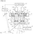
- FIG. 8 shows an EUV light source apparatus 1A according to another embodiment of the present invention.
- the first support wall portion 41 is located closer to the discharge electrodes 21a and 21b than the second support wall portion 51, and a through-hole 45 is formed in the first support wall portion 41 for insertion of the second tubular portion 52.
- first support wall portion 41 of the first support structure 40 and the second support structure 50 overlap each other, and the second tubular portion 52 of the second support structure 50 is inserted into the through-hole 45 of the first support wall portion 41 of the first support structure 40.
- first support structure 40 and the second support structure 50 made of metal, in particular the first support wall portion 41 and the second support wall portion 51 to be disposed extremely close to each other. It is estimated that in this way, two objects in which current flows in opposite directions are placed very close to each other, so that the magnetomotive forces of the first support structure 40 and the second support structure 50 cancel each other out.
- the second support structure 50 has outer wall portions 57 that protrude from the second support wall portion 51 and that face outer surfaces of the first support wall portion 41.
- adjacent portions of the first support structure 40 and the second support structure 50 are increased, so that the magnetomotive forces of the first support structure 40 and the second support structure 50 further cancel each other out, and the inductance of the entire discharge circuit is further reduced.
- the rotational shaft 23a of the motor 22a fixed to the cathode 21a is supported by the bearing B1 located in the end wall 43 of the first tubular portion 42 of the first support structure 40 and another bearing B2 located in the second support wall portion 51 of the second support structure 50.
- the first support wall portion 41 of the first support structure 40 has a through-hole 46 through which the rotational shaft 23a passes.
- another bearing may be disposed in the through-hole 46 for supporting the rotational shaft 23a.
- the rotational shaft 23b of the motor 22b fixed to the anode 21b is supported by the bearing B3 located in the end wall 53 of the second tubular portion 52 of the second support structure 50 and another bearing B4 located in the second support wall portion 51 of the second support structure 50.
- FIG. 9 shows an EUV light source apparatus 1B according to another embodiment of the present invention.
- the first support structure 40 has two outer wall portions 47 that protrude from the first support wall portion 41 and that face outer surfaces of the second support wall portion 51.
- the two outer wall portions 47 are disposed on two sides of the first support wall portion 41 and face the two side surfaces of the second supportwall portion 51.
- the outer wall portions 57 may be disposed on the top and bottom of the first support wall portion 41 and may face the top and bottom surfaces of the second support wall portion 51.
- the outer wall portions 47 may surround the second support wall portion 51 all around.
- FIG. 10 shows an EUV light source apparatus 1C according to another embodiment of the present invention.
- the axes of the discharge electrodes 21a and 21b are not parallel.
- the spacing between the rotational shafts 23a and 23b is narrower on the side of the motors and wider on the side of the electrodes. Therefore, the first tubular portion 42 is inclined with respect to the first support wall portion 41, and the second tubular portion 52 is inclined with respect to the second support wall portion 51.
Landscapes
- Physics & Mathematics (AREA)
- Engineering & Computer Science (AREA)
- Plasma & Fusion (AREA)
- Optics & Photonics (AREA)
- General Physics & Mathematics (AREA)
- Exposure And Positioning Against Photoresist Photosensitive Materials (AREA)
- X-Ray Techniques (AREA)
- Preparing Plates And Mask In Photomechanical Process (AREA)
- Exposure Of Semiconductors, Excluding Electron Or Ion Beam Exposure (AREA)
Abstract
Description
- The present invention relates to extreme ultraviolet light source apparatuses.
- Recently, due to increasing miniaturization and integration of semiconductor integrated circuits, shortening of a wavelength of an exposure light source has been promoted. As a next-generation light source for exposing semiconductors, an extreme ultraviolet light source apparatus (hereinafter also referred to as an "EUV light source apparatus") that emits extreme ultraviolet light (hereinafter also referred to as "EUV (extreme ultraviolet) light") having a wavelength of 13.5 nm has been developed.
- There are several known methods for generating EUV light (EUV radiation) in an EUV light source apparatus. One method is to generate a high-temperature plasma by heating and exciting an extreme ultraviolet light radiation subject (hereinafter, also referred to as "EUV radiation subject"), and to generate EUV light emitted from the high-temperature plasma.
- EUV light source apparatuses that employ such a method are classified into an LPP (Laser Produced Plasma) method and a DPP (Discharge Produced Plasma) method, depending on the generation scheme.
- An EUV light source apparatus of the DPP type applies a high voltage to a gap between electrodes in which a discharge gas containing EUV radiation subject (plasma raw material in a gas phase) is supplied, to generate a high-density and high-temperature plasma by discharge, and utilizes extreme ultraviolet light radiated therefrom. As a specific DPP method as disclosed, for example, in
Patent Document 1, a method is proposed in which a liquid high-temperature plasma raw material (for example, Sn (tin)) is supplied to surfaces of electrodes that generate a discharge, an energy beam such as a laser beam is directed to the raw material to vaporize the raw material, and a high-temperature plasma is generated by the discharge. Such an approach may be referred to as LDP (Laser Assisted Discharge Plasma). - In the technology disclosed in
Patent Document 1, a pair of disk-shaped rotating electrodes are used to reduce a thermal load on the electrodes. The electrodes are arranged so that their peripheral edges are close to each other. Pulsed power for discharge is applied to the rotating electrodes at a fixed period (e.g., 4 kHz or higher), so that a plasma that emits extreme ultraviolet light is generated at the fixed period. - Patent Document 1:
JP-A-2017-103120 - To generate plasma in an energy efficient manner (i.e., to reduce loss of energy needed for plasma generation), it is desirable to make the rise of the discharge current between both the rotating electrodes faster.
- Accordingly, it is an object of the present invention to provide an extreme ultraviolet light source apparatus that can enable faster rising of discharge current.
- In accordance with the present invention, there is provided an extreme ultraviolet light source apparatus, including a disk-shaped cathode; a first rotational shaft made of a metal to which the cathode is connected; a disc-shaped anode disposed apart from the cathode; a second rotational shaft made of a metal to which the anode is connected; a first tin supplier configured to coat the cathode with liquid-phase tin; a second tin supplier configured to coat the anode with liquid-phase tin; an energy beam irradiation device configured to irradiate the tin on the cathode with an energy beam to vaporize the tin and generate gas-phase tin in a gap between the cathode and the anode; an electric power supply configured to supply electric power to the cathode and anode to cause a discharge between the cathode and anode for generating a plasma in the gap between the cathode and anode, the plasma emitting extreme ultraviolet light; a first support structure made of a metal supporting the cathode; and a second support structure made of a metal supporting the anode. The first support structure and the second support structure are not in contact with each other. The first support structure has a first support wall portion and a first tubular portion protruding from the first support wall portion and surrounding the first rotational shaft, and the first tubular portion is disposed between the first support wall portion and the cathode. The second support structure has a second support wall portion and a second tubular portion protruding from the second support wall portion and surrounding the second rotational shaft, and the second tubular portion is disposed between the second support wall portion and the anode. The first support wall portion and the second support wall portion overlap each other. The first support wall portion has a through-hole through which the second tubular portion is inserted, or the second support wall portion has a through-hole through which the first tubular portion is inserted.
- In this aspect, the rise of the discharge current that flows between the cathode and anode can be made faster. This reduces loss of the energy needed for plasma generation and increases the luminance of the extreme ultraviolet light generated. The reason for faster occurrence of the rise of the discharge current is not certain, but can be estimated as follows: The first and second support structures made of metal that respectively support the cathode and the anode constitute a discharge circuit that causes a discharge between the cathode and the anode. In this aspect, the first support wall portion of the first support structure and the second support wall portion of the second support structure overlap each other, and a tubular portion of a support structure is inserted into a through-hole in the support wall portion of the other support structure. This allows the first and second support structures made of metal, in particular the first and second support wall portions to be disposed extremely close to each other. In this way, two objects in which current flows in opposite directions are placed very close to each other, so that the magnetomotive forces of the first support structure and the second support structure cancel each other out. Accordingly, it is estimated that the inductance of the entire discharge circuit can be reduced and that the rise of the discharge current can be made faster.
- Preferably, the first support structure has outer wall portions protruding from the first support wall portion and facing outer surfaces of the second support wall portion.
- In this case, the magnetomotive forces of the first and second support structures further cancel each other out since adjacent portions of the first and second support structures are increased.
- Preferably, the second support structure has outer wall portions protruding from the second support wall portion and facing outer surfaces of the first support wall portion.
- In this case, the magnetomotive forces of the first and second support structures further cancel each other out since adjacent portions of the first and second support structures are increased.
- Preferably, insulators are disposed between the first support structure and the second support structure.
- In this case, the first and second support structures are insulated from each other and the spacing therebetween is properly maintained.
- Preferably, the extreme ultraviolet light source apparatus further includes a support base member made of a metal for supporting the first support structure and the second support structure, and at least one of a gap between the support base member and the first support structure and a gap between the support base member and the second support structure is closed with a capacitor.
- In this case, the capacitor is arranged around the discharge circuit, the inductance of the entire discharge circuit can be further reduced.
- In accordance with an aspect of the present invention, the rise of discharge current can be made faster.
-
-
FIG. 1 is a schematic view of an extreme ultraviolet light source apparatus according to an embodiment of the present invention, showing a cross section of a first support structure that supports a cathode and a second support structure that supports an anode; -
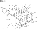
FIG. 2 is a perspective view showing the cathode, the first support structure, the anode, and the second support structure of the extreme ultraviolet light source apparatus; -
FIG. 3 is a perspective view of the cathode and first support structure; -
FIG. 4 is a perspective view of the anode and second support structure; -
FIG. 5 is a schematic view of an extreme ultraviolet light source apparatus according to a comparison example; -
FIG. 6 is a graph showing a current waveform during discharge that occurs between the rotating electrodes in the extreme ultraviolet light source apparatus according to the embodiment; -
FIG. 7 is a graph showing a current waveform during discharge that occurs between the rotating electrodes in the extreme ultraviolet light source apparatus according to the comparison example; -
FIG. 8 is a schematic view of an extreme ultraviolet light source apparatus according to another embodiment of the present invention, showing a cross section of a first support structure that supports a cathode and a second support structure that supports an anode; -
FIG. 9 is a schematic view of an extreme ultraviolet light source apparatus according to another embodiment of the present invention, showing a cross section of a first support structure that supports a cathode and a second support structure that supports an anode; and -
FIG. 10 is a schematic view of an extreme ultraviolet light source apparatus according to another embodiment of the present invention, showing a cross section of a first support structure that supports a cathode and a second support structure that supports an anode. - Hereinafter, with reference to the accompanying drawings, various embodiments according to the present invention will be described. It is of note that the drawings are not necessarily to scale, and certain features may be exaggerated or omitted.
- An extreme ultraviolet light source apparatus (EUV light source apparatus) 1 is an apparatus that is configured to emit extreme ultraviolet light (EUV light) having a wavelength of, for example, 13.5 nm, and that can be used as a light source apparatus of a lithography apparatus for manufacturing semiconductor devices or as a light source apparatus for an apparatus for inspecting masks used for lithography.
- The EUV
light source apparatus 1 according to the embodiment is an EUV light source apparatus of the DPP type. More specifically, the EUV light source apparatus uses an energy beam such as a laser beam to irradiate a plasma raw material in a liquid phase applied to the surfaces of the pair of electrodes to vaporize the plasma raw material, and an electric power source to supply electric power to the electrodes to cause a discharge and generate a high-temperature plasma between the electrodes. EUV light is emitted from the plasma. - As shown in
FIGS. 1 and2 , the EUVlight source apparatus 1 has a pair ofdischarge electrodes discharge electrodes discharge electrode 21a is used as a cathode, whereas thedischarge electrode 21b is used as an anode. Thedischarge electrodes - The
discharge electrodes discharge electrodes cathode 21a and the peripheral portion of theanode 21b are closest, a discharge occurs in the gap between thecathode 21a and theanode 21b, and a high-temperature plasma is generated. Hereinafter, the gap between thecathode 21a and theanode 21b at the position in which the peripheral portion of thecathode 21a and the peripheral portion of theanode 21b are closest is referred to as a "discharge region D". - The
cathode 21a is connected to the rotational shaft (first rotational shaft) 23a of themotor 22a and rotates about the axis of thecathode 21a. Theanode 21b is connected to the rotational shaft (second rotational shaft) 23b of themotor 22b and rotates about the axis of theanode 21b. Thus, thedischarge electrodes separate motors rotational shafts motors - The rotation of each of the
motors controller 15. - The EUV
light source apparatus 1 includes atin reservoir 26a for storing liquid-phase tin 25a, which is a plasma raw material, and atin reservoir 26b for storing liquid-phase tin 25b. Heated liquid-phase tin tin reservoirs - A lower part of the
cathode 21a is immersed in tin 25 in thetin reservoir 26a, and a lower part ofanode 21b is immersed intin 25b in thetin reservoir 26b. As a result, liquid-phase tin (Sn), which is the plasma raw material, adheres to thedischarge electrodes discharge electrodes phase tin - Accordingly, the
tin reservoir 26a alone or the combination of thetin reservoir 26a and themotor 22a serves as a first tin supplier for coating thecathode 21a with the plasma raw material in a liquid phase. Similarly, thetin reservoir 26b alone or the combination of thetin reservoir 26b and themotor 22b serves as a second tin supplier for coating theanode 21b with the plasma raw material in a liquid phase. However, the material supplier is not limited to the type of this embodiment, and may be of other types. - The EUV
light source apparatus 1 includes a laser (energy beam irradiation device) 28 that irradiatestin 25a coated on thecathode 21a with an energy beam to vaporizetin 25a. Thelaser 28 is, for example, Nd:YVO4 laser (Neodymium-doped Yttrium Orthovanadate laser), and emits an infrared laser beam L. However, the energy beam irradiation device may be another device that emits a beam other than a laser beam capable of vaporizingtin 25a. - Illumination timing of the laser beam by the
laser 28 is controlled by thecontroller 15. - The infrared laser beam L emitted from the
laser 28 is directed to amovable mirror 31. Between thelaser 28 and themovable mirror 31, typically a light-collecting means is disposed. The light-collecting means includes, for example, a condensinglens 29. - The infrared laser beam L is reflected by the
movable mirror 31 and illuminates the outer peripheral surface of thecathode 21a in the vicinity of the discharge region D. - The infrared laser beam L reflected by the
movable mirror 31 travels from the side of theanode 21b toward thecathode 21a, passes near the outer peripheral surface of theanode 21b, and then reaches the outer peripheral surface of thecathode 21a. Theanode 21b is retracted behind thecathode 21a toward the upper side ofFig. 1 so as not to interfere with the progress of the infrared laser beam L. - The
liquid phase tin 25a on the outer peripheral surface of thecathode 21a in the vicinity of the discharge region D is vaporized by irradiation with the infrared laser beam L, and a gas-phase plasma raw material is generated in the discharge region D. - To generate a high-temperature plasma in the discharge region D (to transform the plasma raw material in a gas phase to a plasma), a pulse power supply (electric power supply) 35 supplies electric power to the
cathode 21a and theanode 21b, to cause a discharge between thecathode 21a and theanode 21b. Thepulse power supply 35 periodically supplies pulsed electric power to thedischarge electrodes - In this embodiment, the two electric supply lines extending from the
pulse power supply 35 are connected to thetin reservoirs tin reservoirs tin tin reservoirs discharge electrodes tin tin reservoirs pulse power supply 35 supplies pulsed electric power to thetin reservoirs discharge electrodes - When discharge occurs between the
cathode 21a and theanode 21b, the plasma raw material in a gas phase in the discharge region D is heated and excited by a large current, so that a high-temperature plasma is generated. In addition, due to the high heat generated,tin 25b on the outer peripheral surface of theanode 21b in the vicinity of the discharge region D is also converted into plasma. - EUV light E is emitted from the high temperature plasma. EUV light E is used in other optical apparatus (a lithography apparatus or an inspection apparatus for masks).
- The
pulse power supply 35 applies pulsed power to thedischarge electrodes - Next, support structures that support the
discharge electrodes rotational shafts - The EUV
light source apparatus 1 has afirst support structure 40 made of a metal that supports thecathode 21a and asecond support structure 50 made of a metal that supports theanode 21b. Thefirst support structure 40 and thesecond support structure 50 are not in contact with each other and are insulated by a plurality ofinsulators 60, which are interposed therebetween. - As shown in
FIGS. 1 to 3 , thefirst support structure 40 includes a firstsupport wall portion 41 and a firsttubular portion 42 that protrudes from the firstsupport wall portion 41 and surrounds the firstrotational shaft 23a. The firsttubular portion 42 is disposed between the firstsupport wall portion 41 and thecathode 21a. - In this embodiment, the first
support wall portion 41 is a rectangular flat plate. However, the contour of the firstsupport wall portion 41 does not need to be rectangular. In this embodiment, the firsttubular portion 42 has the shape of a hollow square pipe. However, the firsttubular portion 42 may have a shape of a cylinder or other tubular shape. In this embodiment, the firsttubular portion 42 completely surrounds therotational shaft 23a, but the firsttubular portion 42 may have a hole or notch formed therein. - At the end of the first
tubular portion 42 opposite to the firstsupport wall portion 41, anend wall 43 is provided on which a bearing B1 is mounted. The bearing B1 supports therotational shaft 23a to which thecathode 21a is fixed. Although not shown, sealing members are provided around the bearing B1 to keep the discharge region D in vacuum. Theend wall 43 is also used as a wall of thetin reservoir 26a. - As shown in
FIGS. 1 ,2 , and4 , thesecond support structure 50 includes a secondsupport wall portion 51 and a secondtubular portion 52 that protrudes from the secondsupport wall portion 51 and surrounds therotational shaft 23b. The secondtubular portion 52 is disposed between the secondsupport wall portion 51 and theanode 21b. - In this embodiment, the second
support wall portion 51 is a rectangular flat plate. However, the contour of thesecond supportwall portion 51 does not need to be rectangular. In this embodiment, the secondtubular portion 52 has the shape of a hollow square pipe. However, the secondtubular portion 52 may have a shape of a cylinder or other tubular shape. In this embodiment, the secondtubular portion 52 completely surrounds therotational shaft 23a, but the secondtubular portion 52 may have a hole or notch formed therein. - At the end of the second
tubular portion 52 opposite to the secondsupport wall portion 51, anend wall 53 is provided on which a bearing B3 is mounted. The bearing B3 supports therotational shaft 23b to which theanode 21b is fixed. Although not shown, sealing members are provided around the bearing B3 to keep the discharge region D in vacuum. Theend wall 53 is also used as a wall of thetin reservoir 26b. - The first
support wall portion 41 and the secondsupport wall portion 51 overlap each other. In this embodiment, the secondsupport wall portion 51 is positioned closer to thedischarge electrodes support wall portion 41, and a through-hole 55 is formed in the secondsupport wall portion 51 through which the firsttubular portion 42 is inserted. In this embodiment, the firsttubular portion 42 and the secondtubular portion 52 are arranged approximately parallel to each other, and therotational shafts - The
rotational shaft 23a of themotor 22a fixed to thecathode 21a is supported by the bearing B1 located in theend wall 43 of the firsttubular portion 42 of thefirst support structure 40 and another bearing B2 located in the firstsupport wall portion 41 of thefirst support structure 40. - The
rotational shaft 23b of themotor 22b fixed to theanode 21 b is supported by the bearing B3 located in theend wall 53 of the secondtubular portion 52 of thesecond support structure 50 and another bearing B4 located in the firstsupport wall portion 41 of thefirst support structure 40. The secondsupport wall portion 51 of thesecond support structure 50 has a through-hole 56 through which therotational shaft 23b passes. Instead of or in addition to the bearing B4 disposed in the firstsupport wall portion 41, another bearing may be disposed in the through-hole 56 for supporting therotational shaft 23b. - In this embodiment, the
second support structure 50 has twoouter wall portions 57 that protrude from the secondsupport wall portion 51 and face outer surfaces of the firstsupport wall portion 41. The twoouter wall portions 57 are disposed on two sides of the secondsupport wall portion 51 and face the two side surfaces of the firstsupport wall portion 41. However, theouter wall portions 57 may be disposed on the top and bottom of the secondsupport wall portion 51 and may face the top and bottom surfaces of the firstsupport wall portion 41. Theouter wall portions 57 may surround the firstsupport wall portion 41 all around. - The EUV
light source apparatus 1 further has asupport base member 65 made of a metal for supporting thefirst support structure 40 and thesecond support structure 50. A gap between thesupport base member 65 and thefirst support structure 40 and a gap between thesupport base member 65 and thesecond support structure 50 are closed withcapacitors 66. - The
support base member 65 is part of the chamber (housing) of the EUVlight source apparatus 1. The chamber is formed of a rigid material such as a metal. Thedischarge electrodes tin reservoirs tubular portions - The inventors conducted an experiment to investigate the rise of discharge current in the EUV
light source apparatus 1 according to the embodiment. -
FIG. 5 is a schematic view of an EUV light source device used as a comparison example. In the comparison example shown inFIG. 5 , therotational shaft 23a fixed to thecathode 21a is surrounded by the firsttubular portion 42 made of a metal, and therotational shaft 23b fixed to theanode 21b is surrounded by the secondtubular portion 52 made of a metal. However, in this comparison example, there is no equivalent corresponding to the firstsupport wall portion 41, and there is no equivalent corresponding to the secondsupport wall portion 51. Therotational shaft 23a of themotor 22a fixed to thecathode 21a is supported by the bearing B1 located in oneend wall 43 of the firsttubular portion 42 and another bearing B2 located in the other end wall of the firsttubular portion 42. Therotational shaft 23b of themotor 22b fixed to theanode 21b is supported by the bearing B3 located in oneend wall 53 of the secondtubular portion 52 and another bearing B4 located in the other end wall of the secondtubular portion 52. The firsttubular section 42 and the secondtubular section 52 are supported by thesupport base member 65. The first and secondtubular portions support base member 65 are not in contact with each other and are insulated bymultiple insulators 60. -
FIG. 6 is a graph showing a current waveform during the discharge that occurs between thedischarge electrodes light source apparatus 1 according to the embodiment.Fig. 7 is a graph showing a current waveform during the discharge that occurs between thedischarge electrodes light source apparatus 1 according to the comparison example shown inFIG. 5 . - As is clear from
Figs. 6 and 7 , the rise of the discharge current that flowed between thecathode 21a and theanode 21b can be faster in the embodiment than in the comparison example. As a result, there is less loss of energy needed for plasma generation in the embodiment, so that the luminance of the generated EUV light E can be enhanced. - The reason for faster occurrence of the rise of the discharge current by the embodiment is not certain, but can be estimated as follows: The first and
second support structures cathode 21a and theanode 21b constitute a discharge circuit that causes a discharge between thecathode 21a and theanode 21b. Therotational shafts discharge electrodes rotational shafts - The first
support wall portion 41 of thefirst support structure 40 and the secondsupport wall portion 51 of thesecond support structure 50 overlap each other, and the firsttubular portion 42 of thefirst support structure 40 is inserted into the through-hole 55 of the secondsupport wall portion 51 of thesecond support structure 50. This allows that thefirst support structure 40 and thesecond support structure 50 made of metal, in particular the firstsupport wall portion 41 and the secondsupport wall portion 51 to be disposed extremely close to each other. In this way, two objects in which current flows in opposite directions are placed very close to each other, so that the magnetomotive forces of thefirst support structure 40 and thesecond support structure 50 cancel each other out. Accordingly, it is estimated that the inductance of the entire discharge circuit can be reduced and that the rise of the discharge current can be made faster. - In addition, in this embodiment, the
second support structure 50 hasouter wall portions 57 that protrude from the secondsupport wall portion 51 and that face outer surfaces of the firstsupport wall portion 41. Thus, adjacent portions of thefirst support structure 40 and thesecond support structure 50 are increased, so that the magnetomotive forces of thefirst support structure 40 and thesecond support structure 50 further cancel each other out, and the inductance of the entire discharge circuit is further reduced. - In this embodiment, the
insulators 60 are interposed between thefirst support structure 40 and thesecond support structure 50. Thus, thefirst support structure 40 and thesecond support structure 50 are insulated from each other and the spacing therebetween is properly maintained. - In addition, in this embodiment, the
first support structure 40 and thesecond support structure 50 are supported by the metalsupport base member 65, and a gap between thesupport base member 65 and thefirst support structure 40 and a gap between thesupport base member 65 and thesecond support structure 50 are closed withcapacitors 66. In this way, since thecapacitors 66 are arranged around the discharge circuit, the inductance of the entire discharge circuit can be further reduced. -
FIG. 8 shows an EUVlight source apparatus 1A according to another embodiment of the present invention. In the EUVlight source apparatus 1A, contrary to the EUVlight source apparatus 1, the firstsupport wall portion 41 is located closer to thedischarge electrodes support wall portion 51, and a through-hole 45 is formed in the firstsupport wall portion 41 for insertion of the secondtubular portion 52. - In this embodiment, again, the first
support wall portion 41 of thefirst support structure 40 and thesecond support structure 50 overlap each other, and the secondtubular portion 52 of thesecond support structure 50 is inserted into the through-hole 45 of the firstsupport wall portion 41 of thefirst support structure 40. This allows thefirst support structure 40 and thesecond support structure 50 made of metal, in particular the firstsupport wall portion 41 and the secondsupport wall portion 51 to be disposed extremely close to each other. It is estimated that in this way, two objects in which current flows in opposite directions are placed very close to each other, so that the magnetomotive forces of thefirst support structure 40 and thesecond support structure 50 cancel each other out. - In addition, in this embodiment, the
second support structure 50 hasouter wall portions 57 that protrude from the secondsupport wall portion 51 and that face outer surfaces of the firstsupport wall portion 41. Thus, adjacent portions of thefirst support structure 40 and thesecond support structure 50 are increased, so that the magnetomotive forces of thefirst support structure 40 and thesecond support structure 50 further cancel each other out, and the inductance of the entire discharge circuit is further reduced. - In this embodiment, the
rotational shaft 23a of themotor 22a fixed to thecathode 21a is supported by the bearing B1 located in theend wall 43 of the firsttubular portion 42 of thefirst support structure 40 and another bearing B2 located in the secondsupport wall portion 51 of thesecond support structure 50. The firstsupport wall portion 41 of thefirst support structure 40 has a through-hole 46 through which therotational shaft 23a passes. Instead of or in addition to the bearing B2 disposed in the secondtubular portion 52, another bearing may be disposed in the through-hole 46 for supporting therotational shaft 23a. - The
rotational shaft 23b of themotor 22b fixed to theanode 21b is supported by the bearing B3 located in theend wall 53 of the secondtubular portion 52 of thesecond support structure 50 and another bearing B4 located in the secondsupport wall portion 51 of thesecond support structure 50. -
FIG. 9 shows an EUVlight source apparatus 1B according to another embodiment of the present invention. In the EUVlight source apparatus 1B, thefirst support structure 40 has twoouter wall portions 47 that protrude from the firstsupport wall portion 41 and that face outer surfaces of the secondsupport wall portion 51. The twoouter wall portions 47 are disposed on two sides of the firstsupport wall portion 41 and face the two side surfaces of thesecond supportwall portion 51. However, theouter wall portions 57 may be disposed on the top and bottom of the firstsupport wall portion 41 and may face the top and bottom surfaces of the secondsupport wall portion 51. Theouter wall portions 47 may surround the secondsupport wall portion 51 all around. -
FIG. 10 shows an EUV light source apparatus 1C according to another embodiment of the present invention. In the EUV light source apparatus 1C, to facilitate irradiation of the outer peripheral surface of thecathode 21a with the infrared laser beam L, the axes of thedischarge electrodes rotational shafts tubular portion 42 is inclined with respect to the firstsupport wall portion 41, and the secondtubular portion 52 is inclined with respect to the secondsupport wall portion 51. - The present invention has been shown and described with reference to preferred embodiments thereof. However, it will be understood by those skilled in the art that various changes in form and detail may be made without departing from the scope of the invention as defined by the claims. Such variations, alterations, and modifications are intended to be surrounded in the scope of the present invention.
- For example, the above embodiments may be combined as long as they are not contradictory.
-
- 1, 1A, 1B, 1C: Extreme ultraviolet light source apparatus (EUV light source device)
- 21a: Cathode
- 21b: Anode
- 22a: Motor (first tin supplier)
- 22b: Motor (second tin supplier)
- 23a: Rotational shaft (first rotational shaft)
- 23b: Rotational shaft (second rotational shaft)
- 26a: Tin reservoir (first tin supplier)
- 26b: Tin reservoir (second tin supplier)
- 28: Laser (energy beam irradiation device)
- 35: Pulse power supply (electric power supply)
- 40: First support structure
- 41: First support wall portion
- 42: First tubular portion
- 45: Through-hole
- 47: Outer wall portion
- 50: Second support structure
- 51: Second support wall portion
- 52: Second tubular portion
- 55: Through-hole
- 57: Outer wall portion
- 60: Insulator
- 65: Support base member
- L: Infrared laser beam
- P: Plasma
- D: Discharge region
- B1, B2, B3, B4: Bearing
Claims (5)
- An extreme ultraviolet light source apparatus, comprising:a disk-shaped cathode;a first rotational shaft made of a metal to which the cathode is connected;a disc-shaped anode disposed apart from the cathode;a second rotational shaft made of a metal to which the anode is connected;a first tin supplier configured to coat the cathode with liquid-phase tin;a second tin supplier configured to coat the anode with liquid-phase tin;an energy beam irradiation device configured to irradiate the tin on the cathode with an energy beam to vaporize the tin and generate gas-phase tin in a gap between the cathode and the anode;an electric power supply configured to supply electric power to the cathode and anode to cause a discharge between the cathode and anode for generating a plasma in the gap between the cathode and anode, the plasma emitting extreme ultraviolet light;a first support structure made of a metal supporting the cathode; anda second support structure made of a metal supporting the anode,the first support structure and the second support structure being not in contact with each other,the first support structure having a first support wall portion and a first tubular portion protruding from the first support wall portion and surrounding the first rotational shaft, the first tubular portion being disposed between the first support wall portion and the cathode,the second support structure having a second support wall portion and a second tubular portion protruding from the second support wall portion and surrounding the second rotational shaft, the second tubular portion being disposed between the second support wall portion and the anode,the first support wall portion and the second support wall portion overlapping each other,the first support wall portion having a through-hole through which the second tubular portion is inserted, or the second support wall portion having a through-hole through which the first tubular portion is inserted.
- The extreme ultraviolet light source apparatus according to claim 1, wherein the first support structure has outer wall portions protruding from the first support wall portion and facing outer surfaces of the second support wall portion.
- The extreme ultraviolet light source apparatus according to claim 1, wherein the second support structure has outer wall portions protruding from the second support wall portion and facing outer surfaces of the first support wall portion.
- The extreme ultraviolet light source apparatus according to claim 1 or 2, wherein insulators are disposed between the first support structure and the second support structure.
- The extreme ultraviolet light source apparatus according to claim 1 or 2, further comprising a support base member made of a metal for supporting the first support structure and the second support structure,
at least one of a gap between the support base member and the first support structure and a gap between the support base member and the second support structure being closed with a capacitor.
Applications Claiming Priority (2)
| Application Number | Priority Date | Filing Date | Title |
|---|---|---|---|
| JP2020086261A JP7156331B2 (en) | 2020-05-15 | 2020-05-15 | Extreme ultraviolet light source device |
| PCT/JP2021/009330 WO2021229902A1 (en) | 2020-05-15 | 2021-03-09 | Extreme ultraviolet light source device |
Publications (3)
| Publication Number | Publication Date |
|---|---|
| EP4152097A1 true EP4152097A1 (en) | 2023-03-22 |
| EP4152097A4 EP4152097A4 (en) | 2024-06-12 |
| EP4152097B1 EP4152097B1 (en) | 2025-01-01 |
Family
ID=78511372
Family Applications (1)
| Application Number | Title | Priority Date | Filing Date |
|---|---|---|---|
| EP21804523.5A Active EP4152097B1 (en) | 2020-05-15 | 2021-03-09 | Extreme ultraviolet light source device |
Country Status (7)
| Country | Link |
|---|---|
| US (1) | US20230164899A1 (en) |
| EP (1) | EP4152097B1 (en) |
| JP (1) | JP7156331B2 (en) |
| KR (1) | KR102706654B1 (en) |
| CN (1) | CN115668059A (en) |
| TW (1) | TWI840654B (en) |
| WO (1) | WO2021229902A1 (en) |
Family Cites Families (9)
| Publication number | Priority date | Publication date | Assignee | Title |
|---|---|---|---|---|
| JPH04245199A (en) * | 1991-01-30 | 1992-09-01 | Toshiba Corp | Plasma discharge device |
| DE10342239B4 (en) * | 2003-09-11 | 2018-06-07 | Fraunhofer-Gesellschaft zur Förderung der angewandten Forschung e.V. | Method and apparatus for generating extreme ultraviolet or soft x-ray radiation |
| JP4710463B2 (en) * | 2005-07-21 | 2011-06-29 | ウシオ電機株式会社 | Extreme ultraviolet light generator |
| WO2007135587A2 (en) * | 2006-05-16 | 2007-11-29 | Philips Intellectual Property & Standards Gmbh | A method of increasing the conversion efficiency of an euv and/or soft x-ray lamp and a corresponding apparatus |
| DE102007004440B4 (en) | 2007-01-25 | 2011-05-12 | Xtreme Technologies Gmbh | Apparatus and method for generating extreme ultraviolet radiation by means of an electrically operated gas discharge |
| DE102007060807B4 (en) | 2007-12-18 | 2009-11-26 | Fraunhofer-Gesellschaft zur Förderung der angewandten Forschung e.V. | Gas discharge source, in particular for EUV radiation |
| NL1036272A1 (en) * | 2007-12-19 | 2009-06-22 | Asml Netherlands Bv | Radiation source, lithographic apparatus and device manufacturing method. |
| JP5093267B2 (en) * | 2010-03-11 | 2012-12-12 | ウシオ電機株式会社 | Condensing mirror assembly and extreme ultraviolet light source device using the condensing mirror assembly |
| JP2017103120A (en) | 2015-12-02 | 2017-06-08 | ウシオ電機株式会社 | Method and device for measuring electrode state |
-
2020
- 2020-05-15 JP JP2020086261A patent/JP7156331B2/en active Active
-
2021
- 2021-02-26 TW TW110106915A patent/TWI840654B/en active
- 2021-03-09 CN CN202180035400.4A patent/CN115668059A/en not_active Withdrawn
- 2021-03-09 EP EP21804523.5A patent/EP4152097B1/en active Active
- 2021-03-09 WO PCT/JP2021/009330 patent/WO2021229902A1/en not_active Ceased
- 2021-03-09 KR KR1020227035975A patent/KR102706654B1/en active Active
- 2021-03-09 US US17/921,678 patent/US20230164899A1/en not_active Abandoned
Also Published As
| Publication number | Publication date |
|---|---|
| EP4152097A4 (en) | 2024-06-12 |
| TW202147037A (en) | 2021-12-16 |
| KR102706654B1 (en) | 2024-09-13 |
| CN115668059A (en) | 2023-01-31 |
| US20230164899A1 (en) | 2023-05-25 |
| KR20220154224A (en) | 2022-11-21 |
| JP2021179579A (en) | 2021-11-18 |
| EP4152097B1 (en) | 2025-01-01 |
| WO2021229902A1 (en) | 2021-11-18 |
| TWI840654B (en) | 2024-05-01 |
| JP7156331B2 (en) | 2022-10-19 |
Similar Documents
| Publication | Publication Date | Title |
|---|---|---|
| US8040030B2 (en) | Method of increasing the conversion efficiency of an EUV and/or soft X-ray lamp and a corresponding apparatus | |
| KR101058067B1 (en) | Apparatus and method for generating extreme ultraviolet radiation or soft shock radiation | |
| JP5216772B2 (en) | EUV plasma discharge lamp with conveyor belt target | |
| US8227779B2 (en) | Gas discharge source for generating EUV-radiation | |
| US11631579B2 (en) | Extreme ultraviolet light source apparatus and plasma position adjusting method | |
| EP4152097B1 (en) | Extreme ultraviolet light source device | |
| JP7626009B2 (en) | Discharge plasma generating unit and light source device equipped with same | |
| JP2007200919A (en) | Extreme ultraviolet light source device | |
| JP2014146439A (en) | Plasma light source and extreme-ultraviolet light generation method | |
| US11774856B2 (en) | Extreme ultraviolet light source device | |
| JP5590305B2 (en) | Plasma light source and plasma light generation method | |
| JP6834694B2 (en) | Plasma light source | |
| JP6790709B2 (en) | Plasma light source | |
| JP2021179578A (en) | Extreme ultraviolet light source device and method for generating extreme ultraviolet light | |
| JP2017195144A (en) | Plasma light source and method for generating plasma light |
Legal Events
| Date | Code | Title | Description |
|---|---|---|---|
| STAA | Information on the status of an ep patent application or granted ep patent |
Free format text: STATUS: THE INTERNATIONAL PUBLICATION HAS BEEN MADE |
|
| PUAI | Public reference made under article 153(3) epc to a published international application that has entered the european phase |
Free format text: ORIGINAL CODE: 0009012 |
|
| STAA | Information on the status of an ep patent application or granted ep patent |
Free format text: STATUS: REQUEST FOR EXAMINATION WAS MADE |
|
| 17P | Request for examination filed |
Effective date: 20221025 |
|
| AK | Designated contracting states |
Kind code of ref document: A1 Designated state(s): AL AT BE BG CH CY CZ DE DK EE ES FI FR GB GR HR HU IE IS IT LI LT LU LV MC MK MT NL NO PL PT RO RS SE SI SK SM TR |
|
| DAV | Request for validation of the european patent (deleted) | ||
| DAX | Request for extension of the european patent (deleted) | ||
| A4 | Supplementary search report drawn up and despatched |
Effective date: 20240513 |
|
| RIC1 | Information provided on ipc code assigned before grant |
Ipc: H05G 2/00 20060101ALI20240506BHEP Ipc: G03F 7/20 20060101AFI20240506BHEP |
|
| REG | Reference to a national code |
Ref country code: DE Ref legal event code: R079 Free format text: PREVIOUS MAIN CLASS: G03F0007200000 Ipc: H05G0002000000 Ref country code: DE Ref legal event code: R079 Ref document number: 602021024354 Country of ref document: DE Free format text: PREVIOUS MAIN CLASS: G03F0007200000 Ipc: H05G0002000000 |
|
| GRAP | Despatch of communication of intention to grant a patent |
Free format text: ORIGINAL CODE: EPIDOSNIGR1 |
|
| STAA | Information on the status of an ep patent application or granted ep patent |
Free format text: STATUS: GRANT OF PATENT IS INTENDED |
|
| RIC1 | Information provided on ipc code assigned before grant |
Ipc: H05G 2/00 20060101AFI20240912BHEP |
|
| INTG | Intention to grant announced |
Effective date: 20240930 |
|
| GRAS | Grant fee paid |
Free format text: ORIGINAL CODE: EPIDOSNIGR3 |
|
| GRAA | (expected) grant |
Free format text: ORIGINAL CODE: 0009210 |
|
| STAA | Information on the status of an ep patent application or granted ep patent |
Free format text: STATUS: THE PATENT HAS BEEN GRANTED |
|
| AK | Designated contracting states |
Kind code of ref document: B1 Designated state(s): AL AT BE BG CH CY CZ DE DK EE ES FI FR GB GR HR HU IE IS IT LI LT LU LV MC MK MT NL NO PL PT RO RS SE SI SK SM TR |
|
| REG | Reference to a national code |
Ref country code: GB Ref legal event code: FG4D |
|
| REG | Reference to a national code |
Ref country code: CH Ref legal event code: EP |
|
| REG | Reference to a national code |
Ref country code: DE Ref legal event code: R096 Ref document number: 602021024354 Country of ref document: DE |
|
| REG | Reference to a national code |
Ref country code: IE Ref legal event code: FG4D |
|
| PGFP | Annual fee paid to national office [announced via postgrant information from national office to epo] |
Ref country code: DE Payment date: 20250218 Year of fee payment: 5 |
|
| PGFP | Annual fee paid to national office [announced via postgrant information from national office to epo] |
Ref country code: AT Payment date: 20250417 Year of fee payment: 5 |
|
| REG | Reference to a national code |
Ref country code: LT Ref legal event code: MG9D |
|
| REG | Reference to a national code |
Ref country code: NL Ref legal event code: MP Effective date: 20250101 |
|
| REG | Reference to a national code |
Ref country code: AT Ref legal event code: MK05 Ref document number: 1757656 Country of ref document: AT Kind code of ref document: T Effective date: 20250101 |
|
| PG25 | Lapsed in a contracting state [announced via postgrant information from national office to epo] |
Ref country code: NL Free format text: LAPSE BECAUSE OF FAILURE TO SUBMIT A TRANSLATION OF THE DESCRIPTION OR TO PAY THE FEE WITHIN THE PRESCRIBED TIME-LIMIT Effective date: 20250101 |
|
| PG25 | Lapsed in a contracting state [announced via postgrant information from national office to epo] |
Ref country code: FI Free format text: LAPSE BECAUSE OF FAILURE TO SUBMIT A TRANSLATION OF THE DESCRIPTION OR TO PAY THE FEE WITHIN THE PRESCRIBED TIME-LIMIT Effective date: 20250101 |
|
| PG25 | Lapsed in a contracting state [announced via postgrant information from national office to epo] |
Ref country code: PL Free format text: LAPSE BECAUSE OF FAILURE TO SUBMIT A TRANSLATION OF THE DESCRIPTION OR TO PAY THE FEE WITHIN THE PRESCRIBED TIME-LIMIT Effective date: 20250101 |
|
| PG25 | Lapsed in a contracting state [announced via postgrant information from national office to epo] |
Ref country code: ES Free format text: LAPSE BECAUSE OF FAILURE TO SUBMIT A TRANSLATION OF THE DESCRIPTION OR TO PAY THE FEE WITHIN THE PRESCRIBED TIME-LIMIT Effective date: 20250101 |
|
| PG25 | Lapsed in a contracting state [announced via postgrant information from national office to epo] |
Ref country code: NO Free format text: LAPSE BECAUSE OF FAILURE TO SUBMIT A TRANSLATION OF THE DESCRIPTION OR TO PAY THE FEE WITHIN THE PRESCRIBED TIME-LIMIT Effective date: 20250401 Ref country code: IS Free format text: LAPSE BECAUSE OF FAILURE TO SUBMIT A TRANSLATION OF THE DESCRIPTION OR TO PAY THE FEE WITHIN THE PRESCRIBED TIME-LIMIT Effective date: 20250501 |
|
| PG25 | Lapsed in a contracting state [announced via postgrant information from national office to epo] |
Ref country code: HR Free format text: LAPSE BECAUSE OF FAILURE TO SUBMIT A TRANSLATION OF THE DESCRIPTION OR TO PAY THE FEE WITHIN THE PRESCRIBED TIME-LIMIT Effective date: 20250101 |
|
| PG25 | Lapsed in a contracting state [announced via postgrant information from national office to epo] |
Ref country code: LV Free format text: LAPSE BECAUSE OF FAILURE TO SUBMIT A TRANSLATION OF THE DESCRIPTION OR TO PAY THE FEE WITHIN THE PRESCRIBED TIME-LIMIT Effective date: 20250101 Ref country code: PT Free format text: LAPSE BECAUSE OF FAILURE TO SUBMIT A TRANSLATION OF THE DESCRIPTION OR TO PAY THE FEE WITHIN THE PRESCRIBED TIME-LIMIT Effective date: 20250502 |
|
| PG25 | Lapsed in a contracting state [announced via postgrant information from national office to epo] |
Ref country code: BG Free format text: LAPSE BECAUSE OF FAILURE TO SUBMIT A TRANSLATION OF THE DESCRIPTION OR TO PAY THE FEE WITHIN THE PRESCRIBED TIME-LIMIT Effective date: 20250101 Ref country code: GR Free format text: LAPSE BECAUSE OF FAILURE TO SUBMIT A TRANSLATION OF THE DESCRIPTION OR TO PAY THE FEE WITHIN THE PRESCRIBED TIME-LIMIT Effective date: 20250402 |
|
| PG25 | Lapsed in a contracting state [announced via postgrant information from national office to epo] |
Ref country code: AT Free format text: LAPSE BECAUSE OF FAILURE TO SUBMIT A TRANSLATION OF THE DESCRIPTION OR TO PAY THE FEE WITHIN THE PRESCRIBED TIME-LIMIT Effective date: 20250101 |
|
| PG25 | Lapsed in a contracting state [announced via postgrant information from national office to epo] |
Ref country code: CZ Free format text: LAPSE BECAUSE OF FAILURE TO SUBMIT A TRANSLATION OF THE DESCRIPTION OR TO PAY THE FEE WITHIN THE PRESCRIBED TIME-LIMIT Effective date: 20250101 |
|
| PG25 | Lapsed in a contracting state [announced via postgrant information from national office to epo] |
Ref country code: SE Free format text: LAPSE BECAUSE OF FAILURE TO SUBMIT A TRANSLATION OF THE DESCRIPTION OR TO PAY THE FEE WITHIN THE PRESCRIBED TIME-LIMIT Effective date: 20250101 |
|
| REG | Reference to a national code |
Ref country code: DE Ref legal event code: R097 Ref document number: 602021024354 Country of ref document: DE |
|
| PG25 | Lapsed in a contracting state [announced via postgrant information from national office to epo] |
Ref country code: SM Free format text: LAPSE BECAUSE OF FAILURE TO SUBMIT A TRANSLATION OF THE DESCRIPTION OR TO PAY THE FEE WITHIN THE PRESCRIBED TIME-LIMIT Effective date: 20250101 |
|
| PG25 | Lapsed in a contracting state [announced via postgrant information from national office to epo] |
Ref country code: DK Free format text: LAPSE BECAUSE OF FAILURE TO SUBMIT A TRANSLATION OF THE DESCRIPTION OR TO PAY THE FEE WITHIN THE PRESCRIBED TIME-LIMIT Effective date: 20250101 |
|
| PG25 | Lapsed in a contracting state [announced via postgrant information from national office to epo] |
Ref country code: MC Free format text: LAPSE BECAUSE OF FAILURE TO SUBMIT A TRANSLATION OF THE DESCRIPTION OR TO PAY THE FEE WITHIN THE PRESCRIBED TIME-LIMIT Effective date: 20250101 |
|
| PG25 | Lapsed in a contracting state [announced via postgrant information from national office to epo] |
Ref country code: IT Free format text: LAPSE BECAUSE OF FAILURE TO SUBMIT A TRANSLATION OF THE DESCRIPTION OR TO PAY THE FEE WITHIN THE PRESCRIBED TIME-LIMIT Effective date: 20250101 |
|
| PG25 | Lapsed in a contracting state [announced via postgrant information from national office to epo] |
Ref country code: EE Free format text: LAPSE BECAUSE OF FAILURE TO SUBMIT A TRANSLATION OF THE DESCRIPTION OR TO PAY THE FEE WITHIN THE PRESCRIBED TIME-LIMIT Effective date: 20250101 |
|
| REG | Reference to a national code |
Ref country code: CH Ref legal event code: H13 Free format text: ST27 STATUS EVENT CODE: U-0-0-H10-H13 (AS PROVIDED BY THE NATIONAL OFFICE) Effective date: 20251023 |
|
| PG25 | Lapsed in a contracting state [announced via postgrant information from national office to epo] |
Ref country code: RO Free format text: LAPSE BECAUSE OF FAILURE TO SUBMIT A TRANSLATION OF THE DESCRIPTION OR TO PAY THE FEE WITHIN THE PRESCRIBED TIME-LIMIT Effective date: 20250101 |
|
| PG25 | Lapsed in a contracting state [announced via postgrant information from national office to epo] |
Ref country code: SK Free format text: LAPSE BECAUSE OF FAILURE TO SUBMIT A TRANSLATION OF THE DESCRIPTION OR TO PAY THE FEE WITHIN THE PRESCRIBED TIME-LIMIT Effective date: 20250101 |
|
| PLBE | No opposition filed within time limit |
Free format text: ORIGINAL CODE: 0009261 |
|
| STAA | Information on the status of an ep patent application or granted ep patent |
Free format text: STATUS: NO OPPOSITION FILED WITHIN TIME LIMIT |
|
| PG25 | Lapsed in a contracting state [announced via postgrant information from national office to epo] |
Ref country code: LU Free format text: LAPSE BECAUSE OF NON-PAYMENT OF DUE FEES Effective date: 20250309 |
|
| 26N | No opposition filed |
Effective date: 20251002 |
|
| REG | Reference to a national code |
Ref country code: BE Ref legal event code: MM Effective date: 20250331 |
|
| GBPC | Gb: european patent ceased through non-payment of renewal fee |
Effective date: 20250401 |
|
| PG25 | Lapsed in a contracting state [announced via postgrant information from national office to epo] |
Ref country code: GB Free format text: LAPSE BECAUSE OF NON-PAYMENT OF DUE FEES Effective date: 20250401 |
|
| PG25 | Lapsed in a contracting state [announced via postgrant information from national office to epo] |
Ref country code: FR Free format text: LAPSE BECAUSE OF NON-PAYMENT OF DUE FEES Effective date: 20250331 |
|
| PG25 | Lapsed in a contracting state [announced via postgrant information from national office to epo] |
Ref country code: BE Free format text: LAPSE BECAUSE OF NON-PAYMENT OF DUE FEES Effective date: 20250331 |
|
| PG25 | Lapsed in a contracting state [announced via postgrant information from national office to epo] |
Ref country code: CH Free format text: LAPSE BECAUSE OF NON-PAYMENT OF DUE FEES Effective date: 20250331 |
|
| PG25 | Lapsed in a contracting state [announced via postgrant information from national office to epo] |
Ref country code: IE Free format text: LAPSE BECAUSE OF NON-PAYMENT OF DUE FEES Effective date: 20250309 |
|
| PG25 | Lapsed in a contracting state [announced via postgrant information from national office to epo] |
Ref country code: CY Free format text: LAPSE BECAUSE OF FAILURE TO SUBMIT A TRANSLATION OF THE DESCRIPTION OR TO PAY THE FEE WITHIN THE PRESCRIBED TIME-LIMIT Effective date: 20250101 |
|
| PG25 | Lapsed in a contracting state [announced via postgrant information from national office to epo] |
Ref country code: RS Free format text: LAPSE BECAUSE OF FAILURE TO SUBMIT A TRANSLATION OF THE DESCRIPTION OR TO PAY THE FEE WITHIN THE PRESCRIBED TIME-LIMIT Effective date: 20250101 |
|
| PG25 | Lapsed in a contracting state [announced via postgrant information from national office to epo] |
Ref country code: LT Free format text: LAPSE BECAUSE OF FAILURE TO SUBMIT A TRANSLATION OF THE DESCRIPTION OR TO PAY THE FEE WITHIN THE PRESCRIBED TIME-LIMIT Effective date: 20250101 |
|
| PG25 | Lapsed in a contracting state [announced via postgrant information from national office to epo] |
Ref country code: TR Free format text: LAPSE BECAUSE OF FAILURE TO SUBMIT A TRANSLATION OF THE DESCRIPTION OR TO PAY THE FEE WITHIN THE PRESCRIBED TIME-LIMIT Effective date: 20250101 |