EP4151974A1 - Combined sensor - Google Patents
Combined sensor Download PDFInfo
- Publication number
- EP4151974A1 EP4151974A1 EP22194029.9A EP22194029A EP4151974A1 EP 4151974 A1 EP4151974 A1 EP 4151974A1 EP 22194029 A EP22194029 A EP 22194029A EP 4151974 A1 EP4151974 A1 EP 4151974A1
- Authority
- EP
- European Patent Office
- Prior art keywords
- thermistor
- lead
- extension part
- combined sensor
- exterior portion
- Prior art date
- Legal status (The legal status is an assumption and is not a legal conclusion. Google has not performed a legal analysis and makes no representation as to the accuracy of the status listed.)
- Granted
Links
Images



Classifications
-
- G—PHYSICS
- G01—MEASURING; TESTING
- G01L—MEASURING FORCE, STRESS, TORQUE, WORK, MECHANICAL POWER, MECHANICAL EFFICIENCY, OR FLUID PRESSURE
- G01L19/00—Details of, or accessories for, apparatus for measuring steady or quasi-steady pressure of a fluent medium insofar as such details or accessories are not special to particular types of pressure gauges
- G01L19/0092—Pressure sensor associated with other sensors, e.g. for measuring acceleration or temperature
-
- G—PHYSICS
- G01—MEASURING; TESTING
- G01K—MEASURING TEMPERATURE; MEASURING QUANTITY OF HEAT; THERMALLY-SENSITIVE ELEMENTS NOT OTHERWISE PROVIDED FOR
- G01K1/00—Details of thermometers not specially adapted for particular types of thermometer
- G01K1/08—Protective devices, e.g. casings
-
- G—PHYSICS
- G01—MEASURING; TESTING
- G01K—MEASURING TEMPERATURE; MEASURING QUANTITY OF HEAT; THERMALLY-SENSITIVE ELEMENTS NOT OTHERWISE PROVIDED FOR
- G01K1/00—Details of thermometers not specially adapted for particular types of thermometer
- G01K1/14—Supports; Fastening devices; Arrangements for mounting thermometers in particular locations
-
- G—PHYSICS
- G01—MEASURING; TESTING
- G01K—MEASURING TEMPERATURE; MEASURING QUANTITY OF HEAT; THERMALLY-SENSITIVE ELEMENTS NOT OTHERWISE PROVIDED FOR
- G01K13/00—Thermometers specially adapted for specific purposes
- G01K13/02—Thermometers specially adapted for specific purposes for measuring temperature of moving fluids or granular materials capable of flow
-
- G—PHYSICS
- G01—MEASURING; TESTING
- G01K—MEASURING TEMPERATURE; MEASURING QUANTITY OF HEAT; THERMALLY-SENSITIVE ELEMENTS NOT OTHERWISE PROVIDED FOR
- G01K7/00—Measuring temperature based on the use of electric or magnetic elements directly sensitive to heat ; Power supply therefor, e.g. using thermoelectric elements
- G01K7/16—Measuring temperature based on the use of electric or magnetic elements directly sensitive to heat ; Power supply therefor, e.g. using thermoelectric elements using resistive elements
- G01K7/22—Measuring temperature based on the use of electric or magnetic elements directly sensitive to heat ; Power supply therefor, e.g. using thermoelectric elements using resistive elements the element being a non-linear resistance, e.g. thermistor
-
- G—PHYSICS
- G01—MEASURING; TESTING
- G01L—MEASURING FORCE, STRESS, TORQUE, WORK, MECHANICAL POWER, MECHANICAL EFFICIENCY, OR FLUID PRESSURE
- G01L19/00—Details of, or accessories for, apparatus for measuring steady or quasi-steady pressure of a fluent medium insofar as such details or accessories are not special to particular types of pressure gauges
- G01L19/0061—Electrical connection means
- G01L19/0069—Electrical connection means from the sensor to its support
- G01L19/0076—Electrical connection means from the sensor to its support using buried connections
-
- G—PHYSICS
- G01—MEASURING; TESTING
- G01L—MEASURING FORCE, STRESS, TORQUE, WORK, MECHANICAL POWER, MECHANICAL EFFICIENCY, OR FLUID PRESSURE
- G01L19/00—Details of, or accessories for, apparatus for measuring steady or quasi-steady pressure of a fluent medium insofar as such details or accessories are not special to particular types of pressure gauges
- G01L19/0061—Electrical connection means
- G01L19/0084—Electrical connection means to the outside of the housing
-
- G—PHYSICS
- G01—MEASURING; TESTING
- G01L—MEASURING FORCE, STRESS, TORQUE, WORK, MECHANICAL POWER, MECHANICAL EFFICIENCY, OR FLUID PRESSURE
- G01L19/00—Details of, or accessories for, apparatus for measuring steady or quasi-steady pressure of a fluent medium insofar as such details or accessories are not special to particular types of pressure gauges
- G01L19/14—Housings
-
- G—PHYSICS
- G01—MEASURING; TESTING
- G01L—MEASURING FORCE, STRESS, TORQUE, WORK, MECHANICAL POWER, MECHANICAL EFFICIENCY, OR FLUID PRESSURE
- G01L19/00—Details of, or accessories for, apparatus for measuring steady or quasi-steady pressure of a fluent medium insofar as such details or accessories are not special to particular types of pressure gauges
- G01L19/14—Housings
- G01L19/142—Multiple part housings
- G01L19/143—Two part housings
Definitions
- the present invention relates to a combined sensor.
- the thermistor is covered with a metal member as a whole and is arranged in the flow path, and thus the thermistor has a high heat transfer property, but is easily radiated and has a low temperature responsiveness.
- a combined sensor includes a pressure detector that detects a pressure of a detection medium flowing through a flow path, a temperature detector that detects a temperature of the detection medium using a thermistor, and a housing portion that houses the temperature detector closer to the flow path than the pressure detector and includes a through hole part at an inner peripheral side of the housing portion, one end of the through hole part being an opening end that is open to the flow path, wherein the temperature detector includes a first lead and a second lead connected to the thermistor, and a thermistor case in which a part of the first lead and a part of the second lead are embedded, the thermistor case includes an extension part that passes through the through hole part of the housing portion, and a ring part that includes a flow hole part having one end continuous with the extension part and another end facing the pressure detector, the detection medium flowing through the flow hole part, the thermistor is supported by the extension part to be arranged outside the opening end of the housing portion, and the extension part is provided by being separated into
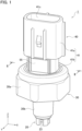
- FIG. 1 is a perspective view of a combined sensor 1 according to an embodiment.
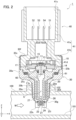
- FIG. 2 is a cross-sectional view of the combined sensor 1 taken along the line II-II of FIG. 1 .
- the combined sensor 1 detects a pressure and a temperature of a detection medium M.
- the detection medium M in the present embodiment is, for example, engine oil flowing through an engine of a vehicle or the like.
- FIG. 2 depicts a part of a mounted member 100 assumed to be an engine including a flow path 101 through which the detection medium M flows.
- the combined sensor 1 is mounted on the mounted member 100 by fastening a screw part 30e, which will be described later, in a mounting hole part 102 formed in the mounted member 100.
- the extension direction of the flow path 101 in the mounted member 100 is defined as an X direction.
- Directions perpendicular to each other on a plane perpendicular to the X direction are defined as a Y direction and a Z direction.
- the passing-through direction of the mounting hole part 102 is along the Z direction.
- Each direction in the combined sensor 1 described below is also adjusted to the directional indication of XYZ.
- the combined sensor 1 includes a pressure sensor module 10, a thermistor unit 20, a housing portion 30, and a connector portion 40.
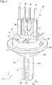
- FIG. 3 is a perspective view of a combination of the pressure sensor module 10 and the thermistor unit 20.
- FIG. 3 also depicts a terminal portion 50 included in the connector portion 40.
- the pressure sensor module 10 is a pressure detector that detects a pressure of the detection medium M flowing through the flow path 101.
- the pressure sensor module 10 includes a pressure sensor element 11, a wiring board 12, a signal processing circuit 13, and a unit case 14.
- the pressure sensor element 11 is a sensor unit used to detect the pressure of the detection medium M.
- the pressure sensor element 11 employs a gauge pressure type based on the atmospheric pressure.
- the pressure range of the pressure sensor element 11 is, for example, 0.5 to 20 MPa.
- the pressure sensor element 11 can be appropriately changed depending on the type of the detection medium M, use conditions, or the like.
- the pressure sensor element 11 may be an absolute pressure type.
- the pressure range may be different from the range of the above example.
- the wiring board 12 is, for example, a printed circuit board and includes the pressure sensor element 11, the signal processing circuit 13, and the like installed thereon.
- the signal processing circuit 13 is an IC chip that performs predetermined processing and the like on a sensor signal output from the pressure sensor element 11.
- the signal processing circuit 13 is electrically connected to the terminal portion 50.
- the unit case 14 is a unit body made from resin and includes a housing space portion 14a for housing the pressure sensor element 11, the wiring board 12, and the signal processing circuit 13.
- the pressure sensor module 10 may include a diaphragm 15, a glass pedestal 16, and a stem 17 as illustrated in FIG. 2 .
- the diaphragm 15 transmits a pressure change in the detection medium M as a deformation force to the pressure sensor element 11.
- the glass pedestal 16 in a tubular shape supports the diaphragm 15.
- the stem 17 is an intermediate member that supports the glass pedestal 16 and is interposed for connecting the pressure sensor module 10 and the thermistor unit 20.
- the stem 17 includes a hole 17a passing therethrough along the central axis.
- the detection medium M flowing through the space portion S which will be described later, reaches the diaphragm 15 through the hole 17a.
- a first O-ring 60 filling a flow hole part 25c included in the thermistor unit 20 is mounted on the outer periphery of the stem 17.
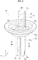
- FIG. 4 is a perspective view of the thermistor unit 20.
- FIG. 5 is a perspective view of a combination of a thermistor 21 and a lead portion 22, which are included in the thermistor unit 20.
- FIG. 6 is a perspective view of a combination of a thermistor exterior portion 23 and the lead portion 22, which are included in the thermistor unit 20.
- the thermistor unit 20 is a temperature detector that detects the temperature of the detection medium M flowing through the flow path 101.
- the thermistor unit 20 includes the thermistor 21 (see FIG. 5 ), the lead portion 22, the thermistor exterior portion 23, a protective material 24 (see FIGS. 2 and 7 ), and a thermistor case 25.
- the thermistor 21 is a sensor unit used to detect the temperature of the detection medium M.
- the thermistor 21 is an electronic component whose resistance value changes due to the change in the temperature of the detection medium M.
- the type of thermistor employed as the thermistor 21 is not limited.
- the thermistor 21 may be an NTC thermistor formed by firing an oxide containing manganese (Mn), nickel (Ni), cobalt (Co), and the like.
- the lead portion 22 is a conductor that makes the thermistor 21 and the terminal portion 50 electrically communicate with each other.
- the lead portion 22 includes a first lead 26 and a second lead 27.
- the first lead 26 functions as an output lead
- the second lead 27 functions as an input lead electrically communicating with an external power source when the combined sensor 1 is used, in accordance with the connection assignment between terminals included in the terminal portion 50 and the pressure sensor module 10.
- the lead portion 22 is formed from a metal having excellent conductivity such as copper (Cu) and is formed into a predetermined shape through an etching process, a pressing process, or the like.
- the first lead 26 and the second lead 27 are symmetrical to each other.
- the thermistor 21 is held along the X direction between a first tip part 26a, which is one end of the first lead 26, and a second tip part 27a, which is one end of the second lead 27.
- a first connection end part 26b, which is the other end of the first lead 26, and a second connection end part 27b, which is the other end of the second lead 27, extend substantially along the Z direction from the first tip part 26a and the second tip part 27a, respectively and are connected to terminals included in the terminal portion 50.
- the interval between the first lead 26 and the second lead 27 is equal as a whole to the interval between the first connection end part 26b and the second connection end part 27b.
- the interval between the first connection end part 26b and the second connection end part 27b is set enough to leave a space portion S provided in an extension part 25a of the thermistor case 25.
- the interval between the first tip part 26a and the second tip part 27a may be smaller than the interval between the first connection end part 26b and the second connection end part 27b.
- the first lead 26 and the second lead 27 each have a flat rod shape as a whole.
- the thermistor exterior portion 23 and the thermistor case 25 are successively formed in separate processes onto the combination of the thermistor 21 and the lead portion 22 in FIG. 5 . Since the first lead 26 and the second lead 27 are formed in a flat rod shape as a whole, it is possible to increase the rigidity and to maintain the posture with ease in the subsequent molding process.
- the thermistor case 25 includes a flow hole part 25c through which the detection medium M flows.
- the first lead 26 may include a first bent part 26c to prevent interference with the flow hole part 25c within the thermistor case 25.
- the second lead 27 may include a second bent part 27c.
- the thermistor exterior portion 23 is a resin part molded to enclose the thermistor 21 mounted on the lead portion 22.
- the shape of the thermistor exterior portion 23 is a rectangular parallelepiped to match the outer shape of the thermistor 21.
- the thermistor exterior portion 23 may be formed into the shape illustrated in FIG. 6 through a transfer molding method using a mold onto the combination of the thermistor 21 and the lead portion 22 in FIG. 5 .
- the resin material forming the thermistor exterior portion 23 may be an epoxy resin excellent in heat resistance, water resistance, electrical insulation, and the like, as thermosetting resin.
- the protective material 24 is a resin material arranged between the extension part 25a of the thermistor case 25 and the thermistor exterior portion 23 to stabilize the holding state of the thermistor exterior portion 23 with the extension part 25a.
- the thermistor case 25 is a unit body made from resin in which a part of the first lead 26 and a part of the second lead 27 are embedded.
- the thermistor case 25 includes the extension part 25a and a ring part 25b, which are continuous with each other as one body.
- the extension part 25a is a column part extending along the Z direction. As illustrated in FIG. 2 , when the thermistor unit 20 is combined as one component of the combined sensor 1, the extension part 25a is a part passing through a through hole part 30d of the housing portion 30 in a non-contact manner.
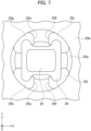
- FIG. 7 is a plan view of the extension part 25a as viewed from the thermistor exterior portion 23.
- the thermistor exterior portion 23 is positioned approximately at the center of the extension part 25a in the XY plane perpendicular to the Z direction.
- the extension part 25a supports the thermistor exterior portion 23 while the thermistor exterior portion 23 is exposed to the outside.
- a surface approximately perpendicular to the Z direction and opposite to the surface held by the extension part 25a is directly exposed to the outside.
- the thermistor 21 is arranged outside an opening end 30g of the through hole part 30d provided in the housing portion 30.
- FIG. 8 is a cross-sectional view of the extension part 25a taken along the line VIII-VIII of FIG. 4 .
- the extension part 25a includes the space portion S formed by being separated into a portion where the first lead 26 is embedded and a portion where the second lead 27 is embedded, along the Z direction, which is the extension direction.
- the extension part 25a includes a first inner wall surface 25e and a second inner wall surface 25f in an intermediate region in the Z direction.
- the first inner wall surface 25e and the second inner wall surface 25f are each parallel to a virtual plane including the Z axis and an axis perpendicular to the Z axis and are opposed to each other in a non-contact manner.
- the axis perpendicular to the Z axis and constituting the virtual plane is the Y axis in the example according to the present embodiment.
- the first inner wall surface 25e and the second inner wall surface 25f are each continuous with the outer peripheral surface of the extension part 25a on both ends in the Y direction.
- the first lead 26 is embedded in a portion that is continuous to the second inner wall surface 25f and is surrounded by the second inner wall surface 25f and a part of the extension part 25a.
- the second lead 27 is embedded in a portion that is continuous to the first inner wall surface 25e and is surrounded by the first inner wall surface 25e and a part of the extension part 25a.
- the space portion S is a space region surrounded by the first inner wall surface 25e and the second inner wall surface 25f.
- the space portion S thus communicates with the outside of the extension part 25a and also with the flow hole part 25c included in the ring part 25b.
- the extension part 25a includes four rod-shaped parts, that is, a first rod-shaped part 25g, a second rod-shaped part 25h, a third rod-shaped part 25i, and a fourth rod-shaped part 25j, at the distal end part where the thermistor exterior portion 23 is held.
- Each of the rod-shaped parts protrudes along the Z direction, which is the extension direction of the extension part 25a.
- the outer peripheral surface of each rod-shaped part coincides with the outer peripheral surface of the extension part 25a.
- a part of each of the rod-shaped parts faces the thermistor exterior portion 23 in a direction orthogonal to the Z direction in a non-contact manner.
- tips of respective rod-shaped parts protrude more than the exposed surface of the thermistor exterior portion 23.
- the rod-shaped parts are arranged spaced apart from each other in the circumferential direction of the extension part 25a. At this time, the rod-shaped parts may be arranged at equal intervals in the circumferential direction of the extension part 25a.
- surfaces facing outward in any of the radial directions on the XY plane from the thermistor exterior portion 23 are directly exposed to the outside from between adjacent rod-shaped parts.
- a part of the side surface of the first rod-shaped part 25g and a part of the side surface of the second rod-shaped part 25h are each continuous with the first inner wall surface 25e.
- a part of the side surface of the third rod-shaped part 25i and a part of the side surface of the fourth rod-shaped part 25j are each continuous with the second inner wall surface 25f.
- the ring part 25b is continuous with the extension part 25a in the central region and along the Z direction.
- the outermost diameter of the ring part 25b is larger than the outer diameter of the extension part 25a.
- the ring part 25b is a part supported by a housing part 30c of the housing portion 30 via a second O-ring 61 when the thermistor unit 20 is combined as one component of the combined sensor 1.
- the ring part 25b includes the flow hole part 25c and a recessed part 25d.
- the flow hole part 25c is provided at the center of the ring part 25b along the Z direction. As illustrated in FIG. 2 , the flow hole part 25c communicates with the space portion S provided in the extension part 25a and thus allows the detection medium M to flow between the end continuous with the extension part 25a and the end facing the pressure sensor module 10.
- the recessed part 25d houses at least a part of the pressure sensor module 10.
- the thermistor case 25 may be formed into the shape illustrated in FIG. 4 through an insert molding method using a mold onto the combination of the thermistor exterior portion 23 and the lead portion 22 illustrated in FIG. 6 .
- the resin material forming the thermistor case 25 may be, for example, PPS (polyphenylenesulfide) resin excellent in heat resistance, flame retardancy, and the like, as thermoplastic resin. That is, the thermistor case 25 is formed from a resin material different from the resin material forming the thermistor exterior portion 23.
- the thermistor unit 20 is combined as one component of the combined sensor 1 before the thermistor unit 20 is combined as one component of the combined sensor 1, a part of the first lead 26 including the first connection end part 26b and a part of the second lead 27 including the second connection end part 27b are simply exposed from the ring part 25b. That is, the thermistor unit 20 is treated as an independent unit before being combined as one component of the combined sensor 1.
- the housing portion 30 is a member formed from a metal material such as stainless steel and serves as a part of the exterior of the combined sensor 1.
- the housing portion 30 includes a housing body 30a and a mounting part 30b, which are continuous with each other as one body.
- the housing body 30a includes the housing part 30c for housing the pressure sensor module 10 and the thermistor unit 20.
- One end of the housing body 30a in the Z direction is continuous with the mounting part 30b.
- the other end of the housing body 30a in the Z direction includes an introduction port 30f for inserting a connection part 41b of the connector portion 40.
- the opening diameter of the introduction port 30f is smaller than the maximum inner diameter of the housing part 30c.
- the housing part 30c houses the pressure sensor module 10 and the thermistor unit 20 so that the pressure sensor module 10 is arranged near the introduction port 30f, while the thermistor unit 20 is arranged near the mounting part 30b.
- the outer periphery of the housing body 30a may be subjected to hexagonal processing for engaging a fastening tool when the combined sensor 1 is mounted on the mounted member 100.
- the mounting part 30b When the combined sensor 1 is mounted on the mounted member 100, the mounting part 30b is connected to the mounting hole part 102 formed in the mounted member 100.
- the screw part 30e is formed on the outer periphery of the mounting part 30b. Note that in FIG. 1 , a depiction of the screw part 30e in the mounting part 30b is omitted.
- the mounting part 30b includes in the inner peripheral surface the through hole part 30d including the opening end 30g as one end. As illustrated in FIG. 2 , when the combined sensor 1 is mounted on the mounted member 100, the opening end 30g is open to the flow path 101.
- the connector portion 40 is formed from a resin material such as PPS resin and serves as a part of the exterior of the combined sensor 1 together with the housing portion 30.
- the connector portion 40 includes a connector 41 and the terminal portion 50.
- the connector 41 connects with an external connector of an external wiring member such as a wire harness routed in a vehicle.
- the connector 41 includes the connector body 41a and the connection part 41b, which are continuous with each other as one body.
- the connector body 41a includes an opening part 41c, one end of which is open to the outside and exposes a part of each terminal included in the terminal portion 50 to the outside.
- the connector body 41a includes an air hole part, which is not illustrated, that allows the opening 41c and a housing recessed part 41d provided in the connection part 41b to communicate with each other.
- the connection part 41b is connected to the housing part 30c of the housing portion 30 when the connector portion 40 is mounted on the housing portion 30.
- connection part 41b The maximum diameter of the connection part 41b is larger than the opening diameter of the introduction port 30f of the housing body 30a.
- the connection part 41b includes the housing recessed part 41d therein. Apart of the pressure sensor module 10 may be housed in the housing recessed part 41d.
- the terminal portion 50 includes a first terminal 51, a second terminal 52, a third terminal 53, a fourth terminal 54, and a potting portion 55.
- Each of the first terminal 51, the second terminal 52, the third terminal 53, and the fourth terminal 54 is a metal rod for electrically connecting the pressure sensor module 10 or the thermistor unit 20 to the external wiring of the external connector.
- the first terminal 51 may be a terminal electrically communicating with the signal processing circuit 13 of the pressure sensor module 10 and transmitting an output related to pressure detection to the outside.
- the second terminal 52 may be an earth terminal electrically communicating with the signal processing circuit 13.
- the third terminal 53 may be a terminal electrically communicating with the signal processing circuit 13 and the second lead 27 of the thermistor unit 20 and supplied with power from the outside.
- the fourth terminal 54 may be a terminal electrically communicating with the first lead 26 of the thermistor unit 20 and transmitting an output related to temperature detection to the outside.
- the potting portion 55 is a resin body protecting welding portions between the third terminal 53 and the second lead 27, and the fourth terminal 54 and the first lead 26, for example.
- a worker prepares the pressure sensor module 10, the thermistor unit 20, the housing portion 30, and the connector portion 40 prior to assembling the combined sensor 1.
- the thermistor unit 20 is manufactured in advance as one unit through a first molding process using a transfer molding method and a second molding process using an insert molding method.
- multiple thermistor units 20 including thermistors 21 of different types are prepared in advance, and thus when assembling the combined sensor 1, the worker can select a thermistor unit 20 including an appropriate thermistor 21 and start the work quickly.
- the pressure sensor module 10 may also be manufactured as one unit in advance. For example, multiple pressure sensor modules 10 having different pressure ranges are prepared in advance, and thus when assembling the combined sensor 1, the worker can select a pressure sensor module 10 having an appropriate pressure range and start the work quickly.
- the worker assembles the pressure sensor module 10 into the recessed part 25d of the thermistor unit 20 via the first O-ring 60 and also joins the terminal portion 50 to the pressure sensor module 10 and the thermistor unit 20.
- the first O-ring 60 is pressed by the stem 17 on the pressure sensor module 10 side and the flow hole part 25c on the thermistor unit 20 side and comes into close contact with both wall parts.
- a unit of a combination of the pressure sensor module 10 and the thermistor unit 20 illustrated in FIG. 3 is formed.
- the worker inserts the second O-ring 61 into the housing part 30c of the housing portion 30 in advance and subsequently inserts the unit of the combination of the pressure sensor module 10 and the thermistor unit 20 into the housing part 30c.
- the extension part 25a of the thermistor unit 20 passes through the second O-ring 61 and then through the through hole part 30d of the housing portion 30.
- the ring part 25b of the thermistor unit 20 is supported by the housing part 30c via the second O-ring 61.
- the thermistor exterior portion 23 enclosing the thermistor 21 protrudes outward from the opening end 30g of the through hole part 30d.
- connection part 41b of the connector portion 40 into the housing part 30c of the housing portion 30, while passing the terminals of the terminal portion 50 into corresponding multiple holes, which are not illustrated, formed in advance in the connector 41 of the connector portion 40.
- the connection part 41b is connected to the housing part 30c
- the connector portion 40 is connected to the housing portion 30.
- the connection part 41b presses at least one of the pressure sensor module 10 or the thermistor unit 20 toward the mounting part 30b.
- the second O-ring 61 is pushed by the ring part 25b of the thermistor unit 20 and the housing part 30c of the housing portion 30 and is brought into close contact with both wall parts. With such a series of operations, the assembly of the combined sensor 1 is completed.
- the flow hole part 25c of the thermistor unit 20 and the stem 17 of the pressure sensor module 10 are sealed via the first O-ring 60 on the inner peripheral surface side of the thermistor unit 20.
- the outer peripheral wall of the ring part 25b of the thermistor unit 20 and the inner peripheral wall of the housing part 30c of the housing portion 30 are sealed via the second O-ring 61 on the outer peripheral surface side of the thermistor unit 20.
- the extension part 25a of the thermistor unit 20 includes the space portion S and is not in contact with the through hole part 30d through which the extension part 25a passes. With such a configuration, the extension part 25a is filled with the detection medium M entering the through hole part 30d from the flow path 101, and the detection medium M also enters the space portion S.
- a part of the stem 17 is in contact with the space portion S of the extension part 25a, and the hole 17a of the stem 17 communicates with the space portion S.
- the pressure sensor element 11 in the pressure sensor module 10 detects the pressure of the detection medium M reaching the diaphragm 15 through the space portion S and the hole 17a.
- the thermistor exterior portion 23 protrudes outward in advance from the opening end 30g of the through hole part 30d.
- the mounting part 30b including the through hole part 30d on the inner peripheral surface side is arranged in the mounting hole part 102 of the mounted member 100, and consequently the thermistor exterior portion 23 is arranged in the flow path 101.
- a surface facing outward in one direction along the Z direction is exposed in the flow path 101 without any interruption.
- the detection medium M flowing through the flow path 101 is directly in contact with the thermistor exterior portion 23 as indicated by the hollow arrow in FIG. 2 , and thus the thermistor 21 enclosed in the thermistor exterior portion 23 captures a temperature change of the detection medium M with high accuracy.
- the thermistor exterior portion 23 is in direct contact with the detection medium M, and thus the thermistor 21 captures a temperature change of the stagnant detection medium M with high accuracy.
- the space portion S provided in the extension part 25a is positioned between the first lead 26 and the second lead 27 embedded in the extension part 25a along the extension direction of the extension part 25a.
- the first lead 26 receives not only the heat of the detection medium M through the outer peripheral wall surface of the extension part 25a but also the heat of the detection medium M through the second inner wall surface 25f facing the space portion S.
- the second lead 27 receives the heat of the detection medium M not only through the outer peripheral wall surface of the extension part 25a but also through the first inner wall surface 25e facing the space portion S.
- the combined sensor 1 includes the pressure detector (pressure sensor module 10) that detects the pressure of the detection medium M flowing through the flow path 101, and the temperature detector (thermistor unit 20) that detects the temperature of the detection medium M using the thermistor 21.
- the combined sensor 1 includes the housing portion 30 housing the temperature detector closer to the flow path 101 than the pressure detector and including the through hole part 30d at the inner surface side thereof, one end of through hole part 30d being the opening end 30g that is open to the flow path 101.
- the temperature detector includes the first lead 26 and the second lead 27 connected to the thermistor 21, and the thermistor case 25 in which a part of the first lead 26 and a part of the second lead 27 are embedded.
- the thermistor case 25 includes the extension part 25a passing through the through hole part 30d of the housing portion 30, and the ring part 25b including the flow hole part 25c for allowing the detection medium M to flow between the end continuous with the extension part 25a and the end facing the pressure detector.
- the thermistor 21 is supported by the extension part 25a to be arranged outside the opening end 30g of the housing portion 30.
- the extension part 25a is provided by being separated into the portion where the first lead 26 is embedded and the portion where the second lead 27 is embedded, along the extension direction of the extension part 25a, and includes the space portion S communicating with the flow hole part 25c of the ring part 25b and with the outside.
- the extension part 25a of the thermistor case 25 is provided with the space portion S for separating the portion where the first lead 26 is embedded and the portion where the second lead 27 is embedded.
- the space portion S is also filled with the detection medium M.
- the first lead 26 and the second lead 27 individually receive heat of the detection medium M through both the outer peripheral wall of the extension part 25a, and the first inner wall surface 25e or the second inner wall surface 25f facing the space portion S.
- the thermistor 21 is arranged outside the opening end 30g of the housing portion 30, and thus when the combined sensor 1 is mounted on, for example, the mounted member 100, the thermistor 21 is arranged in the flow path 101.
- the thermistor 21 detects a temperature change of the detection medium M flowing in the flow path 101 with high accuracy.
- the thermistor 21 it is possible for the thermistor 21 to detect a temperature change of the stagnant detection medium M with high accuracy. That is, it is possible for the combined sensor 1 to improve the temperature measurement accuracy.
- the thermistor 21 may be enclosed in the thermistor exterior portion 23 in a rectangular parallelepiped formed from a resin material.
- the extension part 25a may support the thermistor exterior portion 23 with the thermistor exterior portion 23 exposed to the outside through the first lead 26 and the second lead 27.
- the thermistor exterior portion 23 In the combined sensor 1, it is possible for the thermistor exterior portion 23 to protect the thermistor 21 so that the detection medium M does not directly contact with the thermistor 21. Since the thermistor exterior portion 23 can be formed in a rectangular parallelepiped shape as necessary to enclose the thermistor 21, it is possible to transfer the heat from the detection medium M to the thermistor 21 over a short distance, which can contribute to a reduction in thermal resistance.
- the thermistor case 25 may be formed from a resin material different from the resin material forming the thermistor exterior portion 23.
- the resin material forming the thermistor exterior portion 23 is epoxy resin
- the resin material forming the thermistor case 25 is PPS resin.
- the combined sensor 1 by selecting an appropriate resin material in each step, it is possible to realize manufacturing of the temperature detector through the first molding step using the transfer molding method and the second molding step using the insert molding method.
- the extension part 25a may have multiple rod-shaped parts that partially face the thermistor exterior portion 23 in a direction orthogonal to the extension direction and protrude along the extension direction while being spaced apart from each other.
- the tips of the rod-shaped parts protrude over the exposed surface of the thermistor exterior portion 23 in the extension direction of the extension part 25a, and thus it is possible to protect the thermistor exterior portion 23 from impact and the like. Since the rod-shaped parts are arranged in the circumferential direction of the extension part 25a with a space therebetween, it is possible to keep the exposure of the thermistor exterior portion 23 to the outside, that is, to the flow path 101, unobstructed as much as possible.
- a part of the space portion S included in the extension part 25a may communicate with the periphery of the thermistor exterior portion 23.
- the combined sensor 1 enables the detection medium M flowing in the flow path 101 to be introduced into the space portion S, not only from a region facing the through hole part 30d of the housing portion 30 but also from a region communicating with the periphery of the thermistor exterior portion 23.
- the detection medium M is more easily introduced into the space portion S, and thus it is possible to suppress the heat radiation from the first lead 26 or the second lead 27 more easily.
- the combined sensor 1 may include the connector portion 40 including a terminal, such as the third terminal 53, to which the first lead 26 or the second lead 27 is joined.
- the first connection end part 26b or the second connection end part 27b which are respective ends of the first lead 26 and the second lead 27 connected to the third terminal 53 and the like, may be exposed from the ring part 25b.
- the temperature detector may be one unit including at least the thermistor exterior portion 23 enclosing the thermistor 21, the first lead 26 and the second lead 27, and the thermistor case 25.
- the combined sensor 1 it is possible to simplify the structure using the temperature detector as one unit. Since the temperature detector is manufactured as one unit in advance, it is possible to improve the ease of assembly of the combined sensor 1 by a worker, as described above with respect to the assembly of the combined sensor 1.
Landscapes
- Physics & Mathematics (AREA)
- General Physics & Mathematics (AREA)
- Chemical & Material Sciences (AREA)
- Analytical Chemistry (AREA)
- Nonlinear Science (AREA)
- Measuring Temperature Or Quantity Of Heat (AREA)
- Measuring Fluid Pressure (AREA)
Abstract
Description
- The present invention relates to a combined sensor.
- There have been combined sensors for detecting the two parameters of pressure and temperature of a detection medium.
Japanese Translation of PCT International Application Publication No. 2010-503000 - In the combined sensor disclosed in
Japanese Translation of PCT International Application Publication No. 2010-503000 - It is an object of the present invention to provide a combined sensor that enhances the temperature responsiveness.
- A combined sensor according to the present invention includes a pressure detector that detects a pressure of a detection medium flowing through a flow path, a temperature detector that detects a temperature of the detection medium using a thermistor, and a housing portion that houses the temperature detector closer to the flow path than the pressure detector and includes a through hole part at an inner peripheral side of the housing portion, one end of the through hole part being an opening end that is open to the flow path, wherein the temperature detector includes a first lead and a second lead connected to the thermistor, and a thermistor case in which a part of the first lead and a part of the second lead are embedded, the thermistor case includes an extension part that passes through the through hole part of the housing portion, and a ring part that includes a flow hole part having one end continuous with the extension part and another end facing the pressure detector, the detection medium flowing through the flow hole part, the thermistor is supported by the extension part to be arranged outside the opening end of the housing portion, and the extension part is provided by being separated into a portion where the first lead is embedded and a portion where the second lead is embedded, along an extending direction of the extension part, and includes a space portion communicating with the flow hole part of the ring part and with the outside.
-
-
FIG. 1 is a perspective view of a combined sensor according to an embodiment. -
FIG. 2 is a cross-sectional view of a combined sensor according to an embodiment. -
FIG. 3 is a perspective view of a combination of detecting units. -
FIG. 4 is a perspective view of a thermistor unit. -
FIG. 5 is a perspective view of a combination of a thermistor and lead portions. -
FIG. 6 is a perspective view of a combination of a thermistor exterior portion and the lead portions. -
FIG. 7 is a plan view of an extension part of the thermistor unit as viewed from the thermistor exterior portion end. -
FIG. 8 is a cross-sectional view of the extension part of the thermistor unit. - Various embodiments will be described hereinafter with reference to the accompanying drawings.
- A detailed description is given below of a combined sensor according to an embodiment with reference to the drawings. Note that dimensional ratios in the drawings are exaggerated for convenience of explanation and may be different from actual ratios.
-
FIG. 1 is a perspective view of a combinedsensor 1 according to an embodiment.FIG. 2 is a cross-sectional view of the combinedsensor 1 taken along the line II-II ofFIG. 1 . - The combined
sensor 1 detects a pressure and a temperature of a detection medium M. The detection medium M in the present embodiment is, for example, engine oil flowing through an engine of a vehicle or the like.FIG. 2 depicts a part of a mountedmember 100 assumed to be an engine including aflow path 101 through which the detection medium M flows. The combinedsensor 1 is mounted on the mountedmember 100 by fastening ascrew part 30e, which will be described later, in amounting hole part 102 formed in the mountedmember 100. - In the following drawings, the extension direction of the
flow path 101 in the mountedmember 100 is defined as an X direction. Directions perpendicular to each other on a plane perpendicular to the X direction are defined as a Y direction and a Z direction. The passing-through direction of themounting hole part 102 is along the Z direction. Each direction in the combinedsensor 1 described below is also adjusted to the directional indication of XYZ. - The combined
sensor 1 includes apressure sensor module 10, athermistor unit 20, ahousing portion 30, and aconnector portion 40. -
FIG. 3 is a perspective view of a combination of thepressure sensor module 10 and thethermistor unit 20.FIG. 3 also depicts aterminal portion 50 included in theconnector portion 40. - The
pressure sensor module 10 is a pressure detector that detects a pressure of the detection medium M flowing through theflow path 101. Thepressure sensor module 10 includes apressure sensor element 11, awiring board 12, asignal processing circuit 13, and aunit case 14. - The
pressure sensor element 11 is a sensor unit used to detect the pressure of the detection medium M. In the present embodiment, thepressure sensor element 11 employs a gauge pressure type based on the atmospheric pressure. The pressure range of thepressure sensor element 11 is, for example, 0.5 to 20 MPa. Note that thepressure sensor element 11 can be appropriately changed depending on the type of the detection medium M, use conditions, or the like. For example, thepressure sensor element 11 may be an absolute pressure type. The pressure range may be different from the range of the above example. - The
wiring board 12 is, for example, a printed circuit board and includes thepressure sensor element 11, thesignal processing circuit 13, and the like installed thereon. Thesignal processing circuit 13 is an IC chip that performs predetermined processing and the like on a sensor signal output from thepressure sensor element 11. Thesignal processing circuit 13 is electrically connected to theterminal portion 50. Theunit case 14 is a unit body made from resin and includes ahousing space portion 14a for housing thepressure sensor element 11, thewiring board 12, and thesignal processing circuit 13. - Depending on the type of the
pressure sensor element 11, thepressure sensor module 10 may include adiaphragm 15, aglass pedestal 16, and astem 17 as illustrated inFIG. 2 . Thediaphragm 15 transmits a pressure change in the detection medium M as a deformation force to thepressure sensor element 11. Theglass pedestal 16 in a tubular shape supports thediaphragm 15. Thestem 17 is an intermediate member that supports theglass pedestal 16 and is interposed for connecting thepressure sensor module 10 and thethermistor unit 20. Thestem 17 includes ahole 17a passing therethrough along the central axis. The detection medium M flowing through the space portion S, which will be described later, reaches thediaphragm 15 through thehole 17a. A first O-ring 60 filling aflow hole part 25c included in thethermistor unit 20 is mounted on the outer periphery of thestem 17. -
FIG. 4 is a perspective view of thethermistor unit 20.FIG. 5 is a perspective view of a combination of athermistor 21 and alead portion 22, which are included in thethermistor unit 20.FIG. 6 is a perspective view of a combination of a thermistorexterior portion 23 and thelead portion 22, which are included in thethermistor unit 20. - The
thermistor unit 20 is a temperature detector that detects the temperature of the detection medium M flowing through theflow path 101. Thethermistor unit 20 includes the thermistor 21 (seeFIG. 5 ), thelead portion 22, the thermistorexterior portion 23, a protective material 24 (seeFIGS. 2 and7 ), and athermistor case 25. - The
thermistor 21 is a sensor unit used to detect the temperature of the detection medium M. Thethermistor 21 is an electronic component whose resistance value changes due to the change in the temperature of the detection medium M. The type of thermistor employed as thethermistor 21 is not limited. For example, thethermistor 21 may be an NTC thermistor formed by firing an oxide containing manganese (Mn), nickel (Ni), cobalt (Co), and the like. - The
lead portion 22 is a conductor that makes thethermistor 21 and theterminal portion 50 electrically communicate with each other. Thelead portion 22 includes afirst lead 26 and asecond lead 27. According to the present embodiment, thefirst lead 26 functions as an output lead, and thesecond lead 27 functions as an input lead electrically communicating with an external power source when the combinedsensor 1 is used, in accordance with the connection assignment between terminals included in theterminal portion 50 and thepressure sensor module 10. - The
lead portion 22 is formed from a metal having excellent conductivity such as copper (Cu) and is formed into a predetermined shape through an etching process, a pressing process, or the like. Thefirst lead 26 and thesecond lead 27 are symmetrical to each other. Thethermistor 21 is held along the X direction between afirst tip part 26a, which is one end of thefirst lead 26, and asecond tip part 27a, which is one end of thesecond lead 27. A firstconnection end part 26b, which is the other end of thefirst lead 26, and a secondconnection end part 27b, which is the other end of thesecond lead 27, extend substantially along the Z direction from thefirst tip part 26a and thesecond tip part 27a, respectively and are connected to terminals included in theterminal portion 50. - The interval between the
first lead 26 and thesecond lead 27 is equal as a whole to the interval between the firstconnection end part 26b and the secondconnection end part 27b. Here, the interval between the firstconnection end part 26b and the secondconnection end part 27b is set enough to leave a space portion S provided in anextension part 25a of thethermistor case 25. In contrast, since thefirst tip part 26a and thesecond tip part 27a are arranged closer to thethermistor 21 than the space portion S in the Z direction in theextension part 25a, the interval between thefirst tip part 26a and thesecond tip part 27a may be smaller than the interval between the firstconnection end part 26b and the secondconnection end part 27b. - The
first lead 26 and thesecond lead 27 each have a flat rod shape as a whole. Thethermistor exterior portion 23 and thethermistor case 25 are successively formed in separate processes onto the combination of thethermistor 21 and thelead portion 22 inFIG. 5 . Since thefirst lead 26 and thesecond lead 27 are formed in a flat rod shape as a whole, it is possible to increase the rigidity and to maintain the posture with ease in the subsequent molding process. - As will be described in detail below, the
thermistor case 25 includes aflow hole part 25c through which the detection medium M flows. Thus, thefirst lead 26 may include a firstbent part 26c to prevent interference with theflow hole part 25c within thethermistor case 25. Similarly, thesecond lead 27 may include a secondbent part 27c. - The
thermistor exterior portion 23 is a resin part molded to enclose thethermistor 21 mounted on thelead portion 22. The shape of thethermistor exterior portion 23 is a rectangular parallelepiped to match the outer shape of thethermistor 21. Thethermistor exterior portion 23 may be formed into the shape illustrated inFIG. 6 through a transfer molding method using a mold onto the combination of thethermistor 21 and thelead portion 22 inFIG. 5 . Here, the resin material forming thethermistor exterior portion 23 may be an epoxy resin excellent in heat resistance, water resistance, electrical insulation, and the like, as thermosetting resin. - For example, as illustrated in
FIG. 2 , theprotective material 24 is a resin material arranged between theextension part 25a of thethermistor case 25 and thethermistor exterior portion 23 to stabilize the holding state of thethermistor exterior portion 23 with theextension part 25a. - As illustrated in
FIG. 4 , thethermistor case 25 is a unit body made from resin in which a part of thefirst lead 26 and a part of thesecond lead 27 are embedded. Thethermistor case 25 includes theextension part 25a and aring part 25b, which are continuous with each other as one body. - The
extension part 25a is a column part extending along the Z direction. As illustrated inFIG. 2 , when thethermistor unit 20 is combined as one component of the combinedsensor 1, theextension part 25a is a part passing through a throughhole part 30d of thehousing portion 30 in a non-contact manner. -
FIG. 7 is a plan view of theextension part 25a as viewed from thethermistor exterior portion 23. Thethermistor exterior portion 23 is positioned approximately at the center of theextension part 25a in the XY plane perpendicular to the Z direction. Theextension part 25a supports thethermistor exterior portion 23 while thethermistor exterior portion 23 is exposed to the outside. In particular, among the surfaces of thethermistor exterior portion 23, a surface approximately perpendicular to the Z direction and opposite to the surface held by theextension part 25a is directly exposed to the outside. In the present embodiment, as illustrated inFIG. 2 , thethermistor 21 is arranged outside an openingend 30g of the throughhole part 30d provided in thehousing portion 30. -
FIG. 8 is a cross-sectional view of theextension part 25a taken along the line VIII-VIII ofFIG. 4 . Theextension part 25a includes the space portion S formed by being separated into a portion where thefirst lead 26 is embedded and a portion where thesecond lead 27 is embedded, along the Z direction, which is the extension direction. Here, theextension part 25a includes a firstinner wall surface 25e and a secondinner wall surface 25f in an intermediate region in the Z direction. The firstinner wall surface 25e and the secondinner wall surface 25f are each parallel to a virtual plane including the Z axis and an axis perpendicular to the Z axis and are opposed to each other in a non-contact manner. Here, the axis perpendicular to the Z axis and constituting the virtual plane is the Y axis in the example according to the present embodiment. The firstinner wall surface 25e and the secondinner wall surface 25f are each continuous with the outer peripheral surface of theextension part 25a on both ends in the Y direction. Thefirst lead 26 is embedded in a portion that is continuous to the secondinner wall surface 25f and is surrounded by the secondinner wall surface 25f and a part of theextension part 25a. In contrast, thesecond lead 27 is embedded in a portion that is continuous to the firstinner wall surface 25e and is surrounded by the firstinner wall surface 25e and a part of theextension part 25a. That is, the space portion S is a space region surrounded by the firstinner wall surface 25e and the secondinner wall surface 25f. The space portion S thus communicates with the outside of theextension part 25a and also with theflow hole part 25c included in thering part 25b. - Further, as illustrated in
FIG. 7 , theextension part 25a includes four rod-shaped parts, that is, a first rod-shapedpart 25g, a second rod-shapedpart 25h, a third rod-shapedpart 25i, and a fourth rod-shapedpart 25j, at the distal end part where thethermistor exterior portion 23 is held. Each of the rod-shaped parts protrudes along the Z direction, which is the extension direction of theextension part 25a. In the present embodiment, the outer peripheral surface of each rod-shaped part coincides with the outer peripheral surface of theextension part 25a. A part of each of the rod-shaped parts faces thethermistor exterior portion 23 in a direction orthogonal to the Z direction in a non-contact manner. That is, in the Z direction, tips of respective rod-shaped parts protrude more than the exposed surface of thethermistor exterior portion 23. The rod-shaped parts are arranged spaced apart from each other in the circumferential direction of theextension part 25a. At this time, the rod-shaped parts may be arranged at equal intervals in the circumferential direction of theextension part 25a. Here, among the surfaces of thethermistor exterior portion 23, surfaces facing outward in any of the radial directions on the XY plane from thethermistor exterior portion 23 are directly exposed to the outside from between adjacent rod-shaped parts. - In the
extension part 25a, as illustrated inFIG. 7 , a part of the side surface of the first rod-shapedpart 25g and a part of the side surface of the second rod-shapedpart 25h are each continuous with the firstinner wall surface 25e. In a similar manner, a part of the side surface of the third rod-shapedpart 25i and a part of the side surface of the fourth rod-shapedpart 25j are each continuous with the secondinner wall surface 25f. With such a configuration, a part of the space portion S communicates with the periphery of thethermistor exterior portion 23 through the space between the first rod-shapedpart 25g and the second rod-shapedpart 25h and the space between the third rod-shapedpart 25i and the fourth rod-shapedpart 25j. - The
ring part 25b is continuous with theextension part 25a in the central region and along the Z direction. The outermost diameter of thering part 25b is larger than the outer diameter of theextension part 25a. As illustrated inFIG. 2 , thering part 25b is a part supported by ahousing part 30c of thehousing portion 30 via a second O-ring 61 when thethermistor unit 20 is combined as one component of the combinedsensor 1. - The
ring part 25b includes theflow hole part 25c and a recessedpart 25d. Theflow hole part 25c is provided at the center of thering part 25b along the Z direction. As illustrated inFIG. 2 , theflow hole part 25c communicates with the space portion S provided in theextension part 25a and thus allows the detection medium M to flow between the end continuous with theextension part 25a and the end facing thepressure sensor module 10. The recessedpart 25d houses at least a part of thepressure sensor module 10. - The
thermistor case 25 may be formed into the shape illustrated inFIG. 4 through an insert molding method using a mold onto the combination of thethermistor exterior portion 23 and thelead portion 22 illustrated inFIG. 6 . Here, the resin material forming thethermistor case 25 may be, for example, PPS (polyphenylenesulfide) resin excellent in heat resistance, flame retardancy, and the like, as thermoplastic resin. That is, thethermistor case 25 is formed from a resin material different from the resin material forming thethermistor exterior portion 23. - As illustrated in
FIG. 4 , before thethermistor unit 20 is combined as one component of the combinedsensor 1, a part of thefirst lead 26 including the firstconnection end part 26b and a part of thesecond lead 27 including the secondconnection end part 27b are simply exposed from thering part 25b. That is, thethermistor unit 20 is treated as an independent unit before being combined as one component of the combinedsensor 1. - The
housing portion 30 is a member formed from a metal material such as stainless steel and serves as a part of the exterior of the combinedsensor 1. Thehousing portion 30 includes ahousing body 30a and a mountingpart 30b, which are continuous with each other as one body. - The
housing body 30a includes thehousing part 30c for housing thepressure sensor module 10 and thethermistor unit 20. One end of thehousing body 30a in the Z direction is continuous with the mountingpart 30b. The other end of thehousing body 30a in the Z direction includes anintroduction port 30f for inserting aconnection part 41b of theconnector portion 40. The opening diameter of theintroduction port 30f is smaller than the maximum inner diameter of thehousing part 30c. Thehousing part 30c houses thepressure sensor module 10 and thethermistor unit 20 so that thepressure sensor module 10 is arranged near theintroduction port 30f, while thethermistor unit 20 is arranged near the mountingpart 30b. Note that the outer periphery of thehousing body 30a may be subjected to hexagonal processing for engaging a fastening tool when the combinedsensor 1 is mounted on the mountedmember 100. - When the combined
sensor 1 is mounted on the mountedmember 100, the mountingpart 30b is connected to the mountinghole part 102 formed in the mountedmember 100. In the present embodiment, thescrew part 30e is formed on the outer periphery of the mountingpart 30b. Note that inFIG. 1 , a depiction of thescrew part 30e in the mountingpart 30b is omitted. The mountingpart 30b includes in the inner peripheral surface the throughhole part 30d including the openingend 30g as one end. As illustrated inFIG. 2 , when the combinedsensor 1 is mounted on the mountedmember 100, the openingend 30g is open to theflow path 101. - The
connector portion 40 is formed from a resin material such as PPS resin and serves as a part of the exterior of the combinedsensor 1 together with thehousing portion 30. Theconnector portion 40 includes aconnector 41 and theterminal portion 50. - The
connector 41 connects with an external connector of an external wiring member such as a wire harness routed in a vehicle. Theconnector 41 includes theconnector body 41a and theconnection part 41b, which are continuous with each other as one body. Theconnector body 41a includes anopening part 41c, one end of which is open to the outside and exposes a part of each terminal included in theterminal portion 50 to the outside. Theconnector body 41a includes an air hole part, which is not illustrated, that allows theopening 41c and a housing recessedpart 41d provided in theconnection part 41b to communicate with each other. Theconnection part 41b is connected to thehousing part 30c of thehousing portion 30 when theconnector portion 40 is mounted on thehousing portion 30. The maximum diameter of theconnection part 41b is larger than the opening diameter of theintroduction port 30f of thehousing body 30a. Theconnection part 41b includes the housing recessedpart 41d therein. Apart of thepressure sensor module 10 may be housed in the housing recessedpart 41d. - The
terminal portion 50 includes afirst terminal 51, asecond terminal 52, athird terminal 53, afourth terminal 54, and apotting portion 55. Each of thefirst terminal 51, thesecond terminal 52, thethird terminal 53, and thefourth terminal 54 is a metal rod for electrically connecting thepressure sensor module 10 or thethermistor unit 20 to the external wiring of the external connector. For example, the following functions are assigned to the terminals. Thefirst terminal 51 may be a terminal electrically communicating with thesignal processing circuit 13 of thepressure sensor module 10 and transmitting an output related to pressure detection to the outside. Thesecond terminal 52 may be an earth terminal electrically communicating with thesignal processing circuit 13. Thethird terminal 53 may be a terminal electrically communicating with thesignal processing circuit 13 and thesecond lead 27 of thethermistor unit 20 and supplied with power from the outside. Thefourth terminal 54 may be a terminal electrically communicating with thefirst lead 26 of thethermistor unit 20 and transmitting an output related to temperature detection to the outside. The pottingportion 55 is a resin body protecting welding portions between thethird terminal 53 and thesecond lead 27, and thefourth terminal 54 and thefirst lead 26, for example. - Next, the assembly of the combined
sensor 1 is described. - First, a worker prepares the
pressure sensor module 10, thethermistor unit 20, thehousing portion 30, and theconnector portion 40 prior to assembling the combinedsensor 1. Among these, thethermistor unit 20 is manufactured in advance as one unit through a first molding process using a transfer molding method and a second molding process using an insert molding method. For example,multiple thermistor units 20 includingthermistors 21 of different types are prepared in advance, and thus when assembling the combinedsensor 1, the worker can select athermistor unit 20 including anappropriate thermistor 21 and start the work quickly. - The
pressure sensor module 10 may also be manufactured as one unit in advance. For example, multiplepressure sensor modules 10 having different pressure ranges are prepared in advance, and thus when assembling the combinedsensor 1, the worker can select apressure sensor module 10 having an appropriate pressure range and start the work quickly. - Next, the worker assembles the
pressure sensor module 10 into the recessedpart 25d of thethermistor unit 20 via the first O-ring 60 and also joins theterminal portion 50 to thepressure sensor module 10 and thethermistor unit 20. At this time, the first O-ring 60 is pressed by thestem 17 on thepressure sensor module 10 side and theflow hole part 25c on thethermistor unit 20 side and comes into close contact with both wall parts. Thus, a unit of a combination of thepressure sensor module 10 and thethermistor unit 20 illustrated inFIG. 3 is formed. - Next, the worker inserts the second O-
ring 61 into thehousing part 30c of thehousing portion 30 in advance and subsequently inserts the unit of the combination of thepressure sensor module 10 and thethermistor unit 20 into thehousing part 30c. At this time, theextension part 25a of thethermistor unit 20 passes through the second O-ring 61 and then through the throughhole part 30d of thehousing portion 30. Thering part 25b of thethermistor unit 20 is supported by thehousing part 30c via the second O-ring 61. When thering part 25b is supported by thehousing part 30c, thethermistor exterior portion 23 enclosing thethermistor 21 protrudes outward from the openingend 30g of the throughhole part 30d. - Then, the worker inserts the
connection part 41b of theconnector portion 40 into thehousing part 30c of thehousing portion 30, while passing the terminals of theterminal portion 50 into corresponding multiple holes, which are not illustrated, formed in advance in theconnector 41 of theconnector portion 40. Thus, theconnection part 41b is connected to thehousing part 30c, and theconnector portion 40 is connected to thehousing portion 30. At this time, in thehousing part 30c, theconnection part 41b presses at least one of thepressure sensor module 10 or thethermistor unit 20 toward the mountingpart 30b. The second O-ring 61 is pushed by thering part 25b of thethermistor unit 20 and thehousing part 30c of thehousing portion 30 and is brought into close contact with both wall parts. With such a series of operations, the assembly of the combinedsensor 1 is completed. - Next, the operation of the combined
sensor 1 is described with reference toFIG. 2 . - In the combined
sensor 1, theflow hole part 25c of thethermistor unit 20 and thestem 17 of thepressure sensor module 10 are sealed via the first O-ring 60 on the inner peripheral surface side of thethermistor unit 20. In contrast, the outer peripheral wall of thering part 25b of thethermistor unit 20 and the inner peripheral wall of thehousing part 30c of thehousing portion 30 are sealed via the second O-ring 61 on the outer peripheral surface side of thethermistor unit 20. Theextension part 25a of thethermistor unit 20 includes the space portion S and is not in contact with the throughhole part 30d through which theextension part 25a passes. With such a configuration, theextension part 25a is filled with the detection medium M entering the throughhole part 30d from theflow path 101, and the detection medium M also enters the space portion S. - First, regarding the detection of the pressure of the detection medium M, in the
housing part 30c of thehousing portion 30, a part of thestem 17 is in contact with the space portion S of theextension part 25a, and thehole 17a of thestem 17 communicates with the space portion S. Thepressure sensor element 11 in thepressure sensor module 10 detects the pressure of the detection medium M reaching thediaphragm 15 through the space portion S and thehole 17a. - Next, regarding the detection of the temperature of the detection medium M, the
thermistor exterior portion 23 protrudes outward in advance from the openingend 30g of the throughhole part 30d. Thus, when the combinedsensor 1 is mounted on the mountedmember 100, the mountingpart 30b including the throughhole part 30d on the inner peripheral surface side is arranged in the mountinghole part 102 of the mountedmember 100, and consequently thethermistor exterior portion 23 is arranged in theflow path 101. Here, among the surfaces of thethermistor exterior portion 23, a surface facing outward in one direction along the Z direction is exposed in theflow path 101 without any interruption. Among the surfaces of thethermistor exterior portion 23, surfaces facing outward in any of the radial directions on the XY plane from thethermistor exterior portion 23 are exposed to theflow path 101 through adjacent rod-shaped parts, such as the second rod-shapedpart 25h. Thus, the detection medium M flowing through theflow path 101 is directly in contact with thethermistor exterior portion 23 as indicated by the hollow arrow inFIG. 2 , and thus thethermistor 21 enclosed in thethermistor exterior portion 23 captures a temperature change of the detection medium M with high accuracy. In addition, even when the detection medium M is stagnant in theflow path 101, thethermistor exterior portion 23 is in direct contact with the detection medium M, and thus thethermistor 21 captures a temperature change of the stagnant detection medium M with high accuracy. - Here, the space portion S provided in the
extension part 25a is positioned between thefirst lead 26 and thesecond lead 27 embedded in theextension part 25a along the extension direction of theextension part 25a. Thus, thefirst lead 26 receives not only the heat of the detection medium M through the outer peripheral wall surface of theextension part 25a but also the heat of the detection medium M through the secondinner wall surface 25f facing the space portion S. In a similar manner, thesecond lead 27 receives the heat of the detection medium M not only through the outer peripheral wall surface of theextension part 25a but also through the firstinner wall surface 25e facing the space portion S. - Next, the effect of the combined
sensor 1 is described. - The combined
sensor 1 according to the present embodiment includes the pressure detector (pressure sensor module 10) that detects the pressure of the detection medium M flowing through theflow path 101, and the temperature detector (thermistor unit 20) that detects the temperature of the detection medium M using thethermistor 21. The combinedsensor 1 includes thehousing portion 30 housing the temperature detector closer to theflow path 101 than the pressure detector and including the throughhole part 30d at the inner surface side thereof, one end of throughhole part 30d being the openingend 30g that is open to theflow path 101. The temperature detector includes thefirst lead 26 and thesecond lead 27 connected to thethermistor 21, and thethermistor case 25 in which a part of thefirst lead 26 and a part of thesecond lead 27 are embedded. Thethermistor case 25 includes theextension part 25a passing through the throughhole part 30d of thehousing portion 30, and thering part 25b including theflow hole part 25c for allowing the detection medium M to flow between the end continuous with theextension part 25a and the end facing the pressure detector. Thethermistor 21 is supported by theextension part 25a to be arranged outside the openingend 30g of thehousing portion 30. Theextension part 25a is provided by being separated into the portion where thefirst lead 26 is embedded and the portion where thesecond lead 27 is embedded, along the extension direction of theextension part 25a, and includes the space portion S communicating with theflow hole part 25c of thering part 25b and with the outside. - First, in the combined
sensor 1, theextension part 25a of thethermistor case 25 is provided with the space portion S for separating the portion where thefirst lead 26 is embedded and the portion where thesecond lead 27 is embedded. Thus, even when thethermistor exterior portion 23 is held at the distal end of theextension part 25a to be exposed in theflow path 101, it is possible for the pressure detector to detect the pressure of the detection medium M without any trouble. - In the combined
sensor 1, when the combinedsensor 1 is mounted on the mountedmember 100, for example, the space portion S is also filled with the detection medium M. Thus, as described above as the effect of the temperature detection, thefirst lead 26 and thesecond lead 27 individually receive heat of the detection medium M through both the outer peripheral wall of theextension part 25a, and the firstinner wall surface 25e or the secondinner wall surface 25f facing the space portion S. Thus, it is possible to suppress the heat radiation from thefirst lead 26 or thesecond lead 27, and thus to reduce the heat radiation portion as a whole of the temperature detector and to improve the temperature responsiveness. - As described above, according to the present embodiment, it is possible to provide the combined
sensor 1 that improves the temperature responsiveness. - According to the present embodiment, the
thermistor 21 is arranged outside the openingend 30g of thehousing portion 30, and thus when the combinedsensor 1 is mounted on, for example, the mountedmember 100, thethermistor 21 is arranged in theflow path 101. Thus, as described above as the effect related to the temperature detection, it is possible for thethermistor 21 to detect a temperature change of the detection medium M flowing in theflow path 101 with high accuracy. Further, it is possible for thethermistor 21 to detect a temperature change of the stagnant detection medium M with high accuracy. That is, it is possible for the combinedsensor 1 to improve the temperature measurement accuracy. - In the combined
sensor 1 according to the present embodiment, thethermistor 21 may be enclosed in thethermistor exterior portion 23 in a rectangular parallelepiped formed from a resin material. Here, theextension part 25a may support thethermistor exterior portion 23 with thethermistor exterior portion 23 exposed to the outside through thefirst lead 26 and thesecond lead 27. - In the combined
sensor 1, it is possible for thethermistor exterior portion 23 to protect thethermistor 21 so that the detection medium M does not directly contact with thethermistor 21. Since thethermistor exterior portion 23 can be formed in a rectangular parallelepiped shape as necessary to enclose thethermistor 21, it is possible to transfer the heat from the detection medium M to thethermistor 21 over a short distance, which can contribute to a reduction in thermal resistance. - In the combined
sensor 1 according to the present embodiment, thethermistor case 25 may be formed from a resin material different from the resin material forming thethermistor exterior portion 23. - In the above example, the resin material forming the
thermistor exterior portion 23 is epoxy resin, and the resin material forming thethermistor case 25 is PPS resin. In the combinedsensor 1, by selecting an appropriate resin material in each step, it is possible to realize manufacturing of the temperature detector through the first molding step using the transfer molding method and the second molding step using the insert molding method. - In the combined
sensor 1 according to the present embodiment, theextension part 25a may have multiple rod-shaped parts that partially face thethermistor exterior portion 23 in a direction orthogonal to the extension direction and protrude along the extension direction while being spaced apart from each other. - Here, in the above description, four rod-shaped parts, which are the first rod-shaped
part 25g, the second rod-shapedpart 25h, the third rod-shapedpart 25i, and the fourth rod-shapedpart 25j, are exemplified. - In the combined
sensor 1, the tips of the rod-shaped parts protrude over the exposed surface of thethermistor exterior portion 23 in the extension direction of theextension part 25a, and thus it is possible to protect thethermistor exterior portion 23 from impact and the like. Since the rod-shaped parts are arranged in the circumferential direction of theextension part 25a with a space therebetween, it is possible to keep the exposure of thethermistor exterior portion 23 to the outside, that is, to theflow path 101, unobstructed as much as possible. - In the combined
sensor 1 according to the present embodiment, a part of the space portion S included in theextension part 25a may communicate with the periphery of thethermistor exterior portion 23. - The combined
sensor 1 enables the detection medium M flowing in theflow path 101 to be introduced into the space portion S, not only from a region facing the throughhole part 30d of thehousing portion 30 but also from a region communicating with the periphery of thethermistor exterior portion 23. Thus, the detection medium M is more easily introduced into the space portion S, and thus it is possible to suppress the heat radiation from thefirst lead 26 or thesecond lead 27 more easily. - The combined
sensor 1 according to the present embodiment may include theconnector portion 40 including a terminal, such as thethird terminal 53, to which thefirst lead 26 or thesecond lead 27 is joined. The firstconnection end part 26b or the secondconnection end part 27b, which are respective ends of thefirst lead 26 and thesecond lead 27 connected to thethird terminal 53 and the like, may be exposed from thering part 25b. Here, the temperature detector may be one unit including at least thethermistor exterior portion 23 enclosing thethermistor 21, thefirst lead 26 and thesecond lead 27, and thethermistor case 25. - In the combined
sensor 1, it is possible to simplify the structure using the temperature detector as one unit. Since the temperature detector is manufactured as one unit in advance, it is possible to improve the ease of assembly of the combinedsensor 1 by a worker, as described above with respect to the assembly of the combinedsensor 1. - Although the present invention has been described above by reference to the embodiment, the present invention is not limited to those and the configuration of parts can be replaced with any configuration having a similar function, as long as they lie within the scope of the claims.
Claims (6)
- A combined sensor (1), comprising:a pressure detector (10) that detects a pressure of a detection medium (M) flowing through a flow path (101);a temperature detector (20) that detects a temperature of the detection medium (M) using a thermistor (21); anda housing portion (30) that houses the temperature detector (20) closer to the flow path (101) than the pressure detector (10) and includes a through hole part (30d) at an inner peripheral side of the housing portion (30), one end of the through hole part (30d) being an opening end (30g) that is open to the flow path (101), whereinthe temperature detector (20) includes a first lead (26) and a second lead (27) connected to the thermistor (21), and a thermistor case (25) in which a part of the first lead (26) and a part of the second lead (27) are embedded,the thermistor case (25) includes an extension part (25a) that passes through the through hole part (30d) of the housing portion (30), and a ring part (25b) that includes a flow hole part (25c) having one end continuous with the extension part (25a) and another end facing the pressure detector (10), the detection medium (M) flowing through the flow hole part (25c),the thermistor (21) is supported by the extension part (25a) to be arranged outside the opening end (30g) of the housing portion (30), andthe extension part (25a) is provided by being separated into a portion where the first lead (26) is embedded and a portion where the second lead (27) is embedded, along an extending direction of the extension part (25a), and includes a space portion (S) communicating with the flow hole part (25c) of the ring part (25b) and with the outside.
- The combined sensor (1) according to claim 1, whereinthe thermistor (21) is enclosed in a thermistor exterior portion (23) in a rectangular parallelepiped shape formed from a resin material, andthe extension part (25a) supports via the first lead (26) and the second lead (27), the thermistor exterior portion (23) in a state where the thermistor exterior portion (23) is exposed to the outside.
- The combined sensor (1) according to claim 2, wherein
the thermistor case (25) is formed from a resin material different from the resin material forming the thermistor exterior portion (23). - The combined sensor (1) according to claim 2 or 3, wherein
the extension part (25a) includes multiple rod-shaped parts (25g, 25h, 25i, and 25j), the rod-shaped parts each projecting along the extending direction while being spaced apart from each other, and a part of each of the rod-shaped parts facing the thermistor exterior portion (23) in a direction orthogonal to the extending direction. - The combined sensor (1) according to any one of claims 2 to 4, wherein
a part of the space portion (S) included in the extension part (25a) communicates with a periphery of the thermistor exterior portion (23). - The combined sensor (1) according to any one of claims 2 to 5, further comprising:a connector portion (40) that includes terminals (53, 54) to which the first lead (26) and the second lead (27) are connected, whereinend parts (26b, 27b) of the first lead (26) and the second lead (27), connected to the terminals (53, 54), are exposed from the ring part (25b), andthe temperature detector (20) constitutes one unit including at least the thermistor exterior portion (23) enclosing the thermistor (21), the first lead (26) and the second lead (27), and the thermistor case (25).
Applications Claiming Priority (1)
| Application Number | Priority Date | Filing Date | Title |
|---|---|---|---|
| JP2021144463A JP7381530B2 (en) | 2021-09-06 | 2021-09-06 | composite sensor |
Publications (2)
| Publication Number | Publication Date |
|---|---|
| EP4151974A1 true EP4151974A1 (en) | 2023-03-22 |
| EP4151974B1 EP4151974B1 (en) | 2023-08-30 |
Family
ID=83228736
Family Applications (1)
| Application Number | Title | Priority Date | Filing Date |
|---|---|---|---|
| EP22194029.9A Active EP4151974B1 (en) | 2021-09-06 | 2022-09-06 | Combined sensor |
Country Status (4)
| Country | Link |
|---|---|
| US (1) | US12104973B2 (en) |
| EP (1) | EP4151974B1 (en) |
| JP (1) | JP7381530B2 (en) |
| CN (1) | CN115931210A (en) |
Cited By (1)
| Publication number | Priority date | Publication date | Assignee | Title |
|---|---|---|---|---|
| FR3164786A1 (en) * | 2024-07-19 | 2026-01-23 | Hutchinson | DEVICE FOR MEASURING THE PRESSURE AND TEMPERATURE OF A FLUID |
Families Citing this family (2)
| Publication number | Priority date | Publication date | Assignee | Title |
|---|---|---|---|---|
| DE102022105605B3 (en) * | 2022-03-10 | 2023-03-02 | elobau GmbH & Co.KG | sensor unit |
| JP7783856B2 (en) * | 2023-07-31 | 2025-12-10 | 矢崎総業株式会社 | thermistor |
Citations (2)
| Publication number | Priority date | Publication date | Assignee | Title |
|---|---|---|---|---|
| US7043993B2 (en) * | 2002-10-23 | 2006-05-16 | Denso Corporation | Pressure sensor device having temperature sensor |
| DE102013211479A1 (en) * | 2013-06-19 | 2014-12-24 | Robert Bosch Gmbh | Device for detecting a pressure and a temperature of a medium |
Family Cites Families (13)
| Publication number | Priority date | Publication date | Assignee | Title |
|---|---|---|---|---|
| US5070706A (en) * | 1990-07-10 | 1991-12-10 | Sundstrand Corporation | Superheat sensor with single coupling to fluid line |
| JP2004226325A (en) | 2003-01-24 | 2004-08-12 | Hitachi Ltd | Temperature detector |
| DE102006043324A1 (en) | 2006-09-15 | 2008-03-27 | Robert Bosch Gmbh | Plug-in sensor for combined pressure and temperature measurement |
| JP5273076B2 (en) | 2010-03-24 | 2013-08-28 | 富士電機株式会社 | Integrated semiconductor pressure sensor with temperature sensor |
| DE102014200093A1 (en) * | 2014-01-08 | 2015-07-09 | Robert Bosch Gmbh | Sensor for detecting a temperature and a pressure of a fluid medium |
| CN105466483A (en) * | 2015-06-23 | 2016-04-06 | 武汉飞恩微电子有限公司 | High-precision temperature and pressure sensor |
| US10288513B2 (en) * | 2016-09-14 | 2019-05-14 | Sensata Technologies | Integrated pressure and temperature sensor |
| CN207019811U (en) * | 2017-06-16 | 2018-02-16 | 大陆汽车电子(长春)有限公司 | Temperature sensor |
| JP2019002875A (en) * | 2017-06-19 | 2019-01-10 | 矢崎総業株式会社 | Temperature sensor |
| CN206974562U (en) * | 2017-06-30 | 2018-02-06 | 常州市惠昌传感器有限公司 | High accuracy surface temperature measurement type NTC temperature sensors easy to install |
| ES1218484Y (en) | 2018-08-28 | 2018-12-27 | Cebi Electromechanical Components Spain S A | FLUID TEMPERATURE PRESSURE AND TEMPERATURE DEVICE |
| JP6656336B1 (en) * | 2018-10-24 | 2020-03-04 | 三菱電機株式会社 | Temperature sensor device |
| KR102006750B1 (en) | 2018-11-16 | 2019-08-06 | 주식회사 신한전기 | Sensor assembly for measuring temperature or pressure |
-
2021
- 2021-09-06 JP JP2021144463A patent/JP7381530B2/en active Active
-
2022
- 2022-09-02 US US17/902,138 patent/US12104973B2/en active Active
- 2022-09-05 CN CN202211078808.2A patent/CN115931210A/en not_active Withdrawn
- 2022-09-06 EP EP22194029.9A patent/EP4151974B1/en active Active
Patent Citations (2)
| Publication number | Priority date | Publication date | Assignee | Title |
|---|---|---|---|---|
| US7043993B2 (en) * | 2002-10-23 | 2006-05-16 | Denso Corporation | Pressure sensor device having temperature sensor |
| DE102013211479A1 (en) * | 2013-06-19 | 2014-12-24 | Robert Bosch Gmbh | Device for detecting a pressure and a temperature of a medium |
Cited By (1)
| Publication number | Priority date | Publication date | Assignee | Title |
|---|---|---|---|---|
| FR3164786A1 (en) * | 2024-07-19 | 2026-01-23 | Hutchinson | DEVICE FOR MEASURING THE PRESSURE AND TEMPERATURE OF A FLUID |
Also Published As
| Publication number | Publication date |
|---|---|
| JP7381530B2 (en) | 2023-11-15 |
| CN115931210A (en) | 2023-04-07 |
| JP2023037720A (en) | 2023-03-16 |
| EP4151974B1 (en) | 2023-08-30 |
| US20230070528A1 (en) | 2023-03-09 |
| US12104973B2 (en) | 2024-10-01 |
Similar Documents
| Publication | Publication Date | Title |
|---|---|---|
| EP4151974B1 (en) | Combined sensor | |
| KR0159023B1 (en) | Pressure sensor | |
| US5948989A (en) | Pressure sensor device | |
| KR101981341B1 (en) | Method of integrating a temperature sensing element | |
| US9841335B2 (en) | Sensor for detecting a temperature and a pressure of a fluid medium | |
| KR102006750B1 (en) | Sensor assembly for measuring temperature or pressure | |
| CN1332190C (en) | Pressure sensor module | |
| US12038335B2 (en) | Sensor arrangement having a temperature sensor element and method for its production | |
| JP6159683B2 (en) | Measuring plug | |
| KR20180030398A (en) | Integrated pressure and temperature sensor | |
| JP6624966B2 (en) | Pressure detecting unit and pressure sensor using the same | |
| EP2843386B1 (en) | Pressure detection device and method for producing same | |
| KR102880719B1 (en) | Sensor assembly and physical quantity measuring device | |
| JP2010530540A (en) | Temperature sensor assembly and manufacturing method thereof | |
| CN107407604B (en) | Temperature sensor and its installation structure | |
| CN111351530B (en) | Sensor and preparation method thereof | |
| CN113108823A (en) | Sensor and valve device | |
| CN113108832B (en) | Sensor for detecting a position of a body | |
| CN214308835U (en) | Sensor and valve device | |
| CN115219097B (en) | Pressure sensor device and method for producing the same | |
| US20200249112A1 (en) | Pressure sensor for measuring a pressure of a fluid and method for producing a pressure sensor for measuring a pressure of a fluid | |
| HK40026192A (en) | Sensor assembly and physical quantity measuring device | |
| JP2013096805A (en) | Dynamic quantity sensor | |
| JP2021032807A (en) | Sensor device | |
| JP2018185202A (en) | Physical quantity sensor |
Legal Events
| Date | Code | Title | Description |
|---|---|---|---|
| PUAI | Public reference made under article 153(3) epc to a published international application that has entered the european phase |
Free format text: ORIGINAL CODE: 0009012 |
|
| STAA | Information on the status of an ep patent application or granted ep patent |
Free format text: STATUS: REQUEST FOR EXAMINATION WAS MADE |
|
| 17P | Request for examination filed |
Effective date: 20220906 |
|
| AK | Designated contracting states |
Kind code of ref document: A1 Designated state(s): AL AT BE BG CH CY CZ DE DK EE ES FI FR GB GR HR HU IE IS IT LI LT LU LV MC MK MT NL NO PL PT RO RS SE SI SK SM TR |
|
| RAP3 | Party data changed (applicant data changed or rights of an application transferred) |
Owner name: YAZAKI CORPORATION |
|
| GRAP | Despatch of communication of intention to grant a patent |
Free format text: ORIGINAL CODE: EPIDOSNIGR1 |
|
| STAA | Information on the status of an ep patent application or granted ep patent |
Free format text: STATUS: GRANT OF PATENT IS INTENDED |
|
| INTG | Intention to grant announced |
Effective date: 20230616 |
|
| GRAS | Grant fee paid |
Free format text: ORIGINAL CODE: EPIDOSNIGR3 |
|
| GRAA | (expected) grant |
Free format text: ORIGINAL CODE: 0009210 |
|
| STAA | Information on the status of an ep patent application or granted ep patent |
Free format text: STATUS: THE PATENT HAS BEEN GRANTED |
|
| AK | Designated contracting states |
Kind code of ref document: B1 Designated state(s): AL AT BE BG CH CY CZ DE DK EE ES FI FR GB GR HR HU IE IS IT LI LT LU LV MC MK MT NL NO PL PT RO RS SE SI SK SM TR |
|
| REG | Reference to a national code |
Ref country code: GB Ref legal event code: FG4D |
|
| REG | Reference to a national code |
Ref country code: CH Ref legal event code: EP |
|
| REG | Reference to a national code |
Ref country code: DE Ref legal event code: R096 Ref document number: 602022000416 Country of ref document: DE |
|
| REG | Reference to a national code |
Ref country code: IE Ref legal event code: FG4D |
|
| REG | Reference to a national code |
Ref country code: LT Ref legal event code: MG9D |
|
| REG | Reference to a national code |
Ref country code: NL Ref legal event code: MP Effective date: 20230830 |
|
| REG | Reference to a national code |
Ref country code: AT Ref legal event code: MK05 Ref document number: 1606019 Country of ref document: AT Kind code of ref document: T Effective date: 20230830 |
|
| PG25 | Lapsed in a contracting state [announced via postgrant information from national office to epo] |
Ref country code: GR Free format text: LAPSE BECAUSE OF FAILURE TO SUBMIT A TRANSLATION OF THE DESCRIPTION OR TO PAY THE FEE WITHIN THE PRESCRIBED TIME-LIMIT Effective date: 20231201 |
|
| PG25 | Lapsed in a contracting state [announced via postgrant information from national office to epo] |
Ref country code: IS Free format text: LAPSE BECAUSE OF FAILURE TO SUBMIT A TRANSLATION OF THE DESCRIPTION OR TO PAY THE FEE WITHIN THE PRESCRIBED TIME-LIMIT Effective date: 20231230 |
|
| PG25 | Lapsed in a contracting state [announced via postgrant information from national office to epo] |
Ref country code: SE Free format text: LAPSE BECAUSE OF FAILURE TO SUBMIT A TRANSLATION OF THE DESCRIPTION OR TO PAY THE FEE WITHIN THE PRESCRIBED TIME-LIMIT Effective date: 20230830 Ref country code: RS Free format text: LAPSE BECAUSE OF FAILURE TO SUBMIT A TRANSLATION OF THE DESCRIPTION OR TO PAY THE FEE WITHIN THE PRESCRIBED TIME-LIMIT Effective date: 20230830 Ref country code: NO Free format text: LAPSE BECAUSE OF FAILURE TO SUBMIT A TRANSLATION OF THE DESCRIPTION OR TO PAY THE FEE WITHIN THE PRESCRIBED TIME-LIMIT Effective date: 20231130 Ref country code: LV Free format text: LAPSE BECAUSE OF FAILURE TO SUBMIT A TRANSLATION OF THE DESCRIPTION OR TO PAY THE FEE WITHIN THE PRESCRIBED TIME-LIMIT Effective date: 20230830 Ref country code: LT Free format text: LAPSE BECAUSE OF FAILURE TO SUBMIT A TRANSLATION OF THE DESCRIPTION OR TO PAY THE FEE WITHIN THE PRESCRIBED TIME-LIMIT Effective date: 20230830 Ref country code: IS Free format text: LAPSE BECAUSE OF FAILURE TO SUBMIT A TRANSLATION OF THE DESCRIPTION OR TO PAY THE FEE WITHIN THE PRESCRIBED TIME-LIMIT Effective date: 20231230 Ref country code: HR Free format text: LAPSE BECAUSE OF FAILURE TO SUBMIT A TRANSLATION OF THE DESCRIPTION OR TO PAY THE FEE WITHIN THE PRESCRIBED TIME-LIMIT Effective date: 20230830 Ref country code: GR Free format text: LAPSE BECAUSE OF FAILURE TO SUBMIT A TRANSLATION OF THE DESCRIPTION OR TO PAY THE FEE WITHIN THE PRESCRIBED TIME-LIMIT Effective date: 20231201 Ref country code: FI Free format text: LAPSE BECAUSE OF FAILURE TO SUBMIT A TRANSLATION OF THE DESCRIPTION OR TO PAY THE FEE WITHIN THE PRESCRIBED TIME-LIMIT Effective date: 20230830 Ref country code: AT Free format text: LAPSE BECAUSE OF FAILURE TO SUBMIT A TRANSLATION OF THE DESCRIPTION OR TO PAY THE FEE WITHIN THE PRESCRIBED TIME-LIMIT Effective date: 20230830 |
|
| PG25 | Lapsed in a contracting state [announced via postgrant information from national office to epo] |
Ref country code: PL Free format text: LAPSE BECAUSE OF FAILURE TO SUBMIT A TRANSLATION OF THE DESCRIPTION OR TO PAY THE FEE WITHIN THE PRESCRIBED TIME-LIMIT Effective date: 20230830 Ref country code: NL Free format text: LAPSE BECAUSE OF FAILURE TO SUBMIT A TRANSLATION OF THE DESCRIPTION OR TO PAY THE FEE WITHIN THE PRESCRIBED TIME-LIMIT Effective date: 20230830 |
|
| PG25 | Lapsed in a contracting state [announced via postgrant information from national office to epo] |
Ref country code: ES Free format text: LAPSE BECAUSE OF FAILURE TO SUBMIT A TRANSLATION OF THE DESCRIPTION OR TO PAY THE FEE WITHIN THE PRESCRIBED TIME-LIMIT Effective date: 20230830 |
|
| PG25 | Lapsed in a contracting state [announced via postgrant information from national office to epo] |
Ref country code: SM Free format text: LAPSE BECAUSE OF FAILURE TO SUBMIT A TRANSLATION OF THE DESCRIPTION OR TO PAY THE FEE WITHIN THE PRESCRIBED TIME-LIMIT Effective date: 20230830 Ref country code: RO Free format text: LAPSE BECAUSE OF FAILURE TO SUBMIT A TRANSLATION OF THE DESCRIPTION OR TO PAY THE FEE WITHIN THE PRESCRIBED TIME-LIMIT Effective date: 20230830 Ref country code: ES Free format text: LAPSE BECAUSE OF FAILURE TO SUBMIT A TRANSLATION OF THE DESCRIPTION OR TO PAY THE FEE WITHIN THE PRESCRIBED TIME-LIMIT Effective date: 20230830 Ref country code: EE Free format text: LAPSE BECAUSE OF FAILURE TO SUBMIT A TRANSLATION OF THE DESCRIPTION OR TO PAY THE FEE WITHIN THE PRESCRIBED TIME-LIMIT Effective date: 20230830 Ref country code: DK Free format text: LAPSE BECAUSE OF FAILURE TO SUBMIT A TRANSLATION OF THE DESCRIPTION OR TO PAY THE FEE WITHIN THE PRESCRIBED TIME-LIMIT Effective date: 20230830 Ref country code: CZ Free format text: LAPSE BECAUSE OF FAILURE TO SUBMIT A TRANSLATION OF THE DESCRIPTION OR TO PAY THE FEE WITHIN THE PRESCRIBED TIME-LIMIT Effective date: 20230830 Ref country code: SK Free format text: LAPSE BECAUSE OF FAILURE TO SUBMIT A TRANSLATION OF THE DESCRIPTION OR TO PAY THE FEE WITHIN THE PRESCRIBED TIME-LIMIT Effective date: 20230830 Ref country code: PT Free format text: LAPSE BECAUSE OF FAILURE TO SUBMIT A TRANSLATION OF THE DESCRIPTION OR TO PAY THE FEE WITHIN THE PRESCRIBED TIME-LIMIT Effective date: 20240102 |
|
| PG25 | Lapsed in a contracting state [announced via postgrant information from national office to epo] |
Ref country code: IT Free format text: LAPSE BECAUSE OF FAILURE TO SUBMIT A TRANSLATION OF THE DESCRIPTION OR TO PAY THE FEE WITHIN THE PRESCRIBED TIME-LIMIT Effective date: 20230830 Ref country code: MC Free format text: LAPSE BECAUSE OF FAILURE TO SUBMIT A TRANSLATION OF THE DESCRIPTION OR TO PAY THE FEE WITHIN THE PRESCRIBED TIME-LIMIT Effective date: 20230830 |
|
| REG | Reference to a national code |
Ref country code: DE Ref legal event code: R097 Ref document number: 602022000416 Country of ref document: DE |
|
| PLBE | No opposition filed within time limit |
Free format text: ORIGINAL CODE: 0009261 |
|
| STAA | Information on the status of an ep patent application or granted ep patent |
Free format text: STATUS: NO OPPOSITION FILED WITHIN TIME LIMIT |
|
| PG25 | Lapsed in a contracting state [announced via postgrant information from national office to epo] |
Ref country code: FR Free format text: LAPSE BECAUSE OF NON-PAYMENT OF DUE FEES Effective date: 20231030 Ref country code: SI Free format text: LAPSE BECAUSE OF FAILURE TO SUBMIT A TRANSLATION OF THE DESCRIPTION OR TO PAY THE FEE WITHIN THE PRESCRIBED TIME-LIMIT Effective date: 20230830 |
|
| 26N | No opposition filed |
Effective date: 20240603 |
|
| PG25 | Lapsed in a contracting state [announced via postgrant information from national office to epo] |
Ref country code: BG Free format text: LAPSE BECAUSE OF FAILURE TO SUBMIT A TRANSLATION OF THE DESCRIPTION OR TO PAY THE FEE WITHIN THE PRESCRIBED TIME-LIMIT Effective date: 20230830 |
|
| PG25 | Lapsed in a contracting state [announced via postgrant information from national office to epo] |
Ref country code: BG Free format text: LAPSE BECAUSE OF FAILURE TO SUBMIT A TRANSLATION OF THE DESCRIPTION OR TO PAY THE FEE WITHIN THE PRESCRIBED TIME-LIMIT Effective date: 20230830 |
|
| PG25 | Lapsed in a contracting state [announced via postgrant information from national office to epo] |
Ref country code: LU Free format text: LAPSE BECAUSE OF NON-PAYMENT OF DUE FEES Effective date: 20240906 |
|
| REG | Reference to a national code |
Ref country code: BE Ref legal event code: MM Effective date: 20240930 |
|
| PG25 | Lapsed in a contracting state [announced via postgrant information from national office to epo] |
Ref country code: BE Free format text: LAPSE BECAUSE OF NON-PAYMENT OF DUE FEES Effective date: 20240930 |
|
| PG25 | Lapsed in a contracting state [announced via postgrant information from national office to epo] |
Ref country code: IE Free format text: LAPSE BECAUSE OF NON-PAYMENT OF DUE FEES Effective date: 20240906 |
|
| PGFP | Annual fee paid to national office [announced via postgrant information from national office to epo] |
Ref country code: DE Payment date: 20250730 Year of fee payment: 4 |
|
| PG25 | Lapsed in a contracting state [announced via postgrant information from national office to epo] |
Ref country code: TR Free format text: LAPSE BECAUSE OF FAILURE TO SUBMIT A TRANSLATION OF THE DESCRIPTION OR TO PAY THE FEE WITHIN THE PRESCRIBED TIME-LIMIT Effective date: 20230830 |
|
| PG25 | Lapsed in a contracting state [announced via postgrant information from national office to epo] |
Ref country code: CY Free format text: LAPSE BECAUSE OF FAILURE TO SUBMIT A TRANSLATION OF THE DESCRIPTION OR TO PAY THE FEE WITHIN THE PRESCRIBED TIME-LIMIT; INVALID AB INITIO Effective date: 20220906 |
|
| PG25 | Lapsed in a contracting state [announced via postgrant information from national office to epo] |
Ref country code: HU Free format text: LAPSE BECAUSE OF FAILURE TO SUBMIT A TRANSLATION OF THE DESCRIPTION OR TO PAY THE FEE WITHIN THE PRESCRIBED TIME-LIMIT; INVALID AB INITIO Effective date: 20220906 |
|
| REG | Reference to a national code |
Ref country code: CH Ref legal event code: H13 Free format text: ST27 STATUS EVENT CODE: U-0-0-H10-H13 (AS PROVIDED BY THE NATIONAL OFFICE) Effective date: 20260504 |