EP4151952A1 - Travel route generation device, travel route generation method, and automatic driving system - Google Patents
Travel route generation device, travel route generation method, and automatic driving system Download PDFInfo
- Publication number
- EP4151952A1 EP4151952A1 EP21804109.3A EP21804109A EP4151952A1 EP 4151952 A1 EP4151952 A1 EP 4151952A1 EP 21804109 A EP21804109 A EP 21804109A EP 4151952 A1 EP4151952 A1 EP 4151952A1
- Authority
- EP
- European Patent Office
- Prior art keywords
- vehicle
- route
- information
- basic information
- waypoints
- Prior art date
- Legal status (The legal status is an assumption and is not a legal conclusion. Google has not performed a legal analysis and makes no representation as to the accuracy of the status listed.)
- Withdrawn
Links
Images


Classifications
-
- G—PHYSICS
- G05—CONTROLLING; REGULATING
- G05D—SYSTEMS FOR CONTROLLING OR REGULATING NON-ELECTRIC VARIABLES
- G05D1/00—Control of position, course, altitude or attitude of land, water, air or space vehicles, e.g. using automatic pilots
- G05D1/02—Control of position or course in two dimensions
- G05D1/021—Control of position or course in two dimensions specially adapted to land vehicles
- G05D1/0287—Control of position or course in two dimensions specially adapted to land vehicles involving a plurality of land vehicles, e.g. fleet or convoy travelling
- G05D1/0291—Fleet control
- G05D1/0297—Fleet control by controlling means in a control room
-
- B—PERFORMING OPERATIONS; TRANSPORTING
- B60—VEHICLES IN GENERAL
- B60W—CONJOINT CONTROL OF VEHICLE SUB-UNITS OF DIFFERENT TYPE OR DIFFERENT FUNCTION; CONTROL SYSTEMS SPECIALLY ADAPTED FOR HYBRID VEHICLES; ROAD VEHICLE DRIVE CONTROL SYSTEMS FOR PURPOSES NOT RELATED TO THE CONTROL OF A PARTICULAR SUB-UNIT
- B60W60/00—Drive control systems specially adapted for autonomous road vehicles
- B60W60/001—Planning or execution of driving tasks
- B60W60/0025—Planning or execution of driving tasks specially adapted for specific operations
- B60W60/00253—Taxi operations
-
- G—PHYSICS
- G01—MEASURING; TESTING
- G01C—MEASURING DISTANCES, LEVELS OR BEARINGS; SURVEYING; NAVIGATION; GYROSCOPIC INSTRUMENTS; PHOTOGRAMMETRY OR VIDEOGRAMMETRY
- G01C21/00—Navigation; Navigational instruments not provided for in groups G01C1/00 - G01C19/00
- G01C21/26—Navigation; Navigational instruments not provided for in groups G01C1/00 - G01C19/00 specially adapted for navigation in a road network
- G01C21/34—Route searching; Route guidance
- G01C21/3407—Route searching; Route guidance specially adapted for specific applications
- G01C21/3438—Rendezvous; Ride sharing
-
- G—PHYSICS
- G01—MEASURING; TESTING
- G01C—MEASURING DISTANCES, LEVELS OR BEARINGS; SURVEYING; NAVIGATION; GYROSCOPIC INSTRUMENTS; PHOTOGRAMMETRY OR VIDEOGRAMMETRY
- G01C21/00—Navigation; Navigational instruments not provided for in groups G01C1/00 - G01C19/00
- G01C21/38—Electronic maps specially adapted for navigation; Updating thereof
- G01C21/3863—Structures of map data
- G01C21/3867—Geometry of map features, e.g. shape points, polygons or for simplified maps
-
- G—PHYSICS
- G05—CONTROLLING; REGULATING
- G05D—SYSTEMS FOR CONTROLLING OR REGULATING NON-ELECTRIC VARIABLES
- G05D1/00—Control of position, course, altitude or attitude of land, water, air or space vehicles, e.g. using automatic pilots
- G05D1/02—Control of position or course in two dimensions
- G05D1/021—Control of position or course in two dimensions specially adapted to land vehicles
- G05D1/0231—Control of position or course in two dimensions specially adapted to land vehicles using optical position detecting means
- G05D1/0246—Control of position or course in two dimensions specially adapted to land vehicles using optical position detecting means using a video camera in combination with image processing means
-
- G—PHYSICS
- G05—CONTROLLING; REGULATING
- G05D—SYSTEMS FOR CONTROLLING OR REGULATING NON-ELECTRIC VARIABLES
- G05D1/00—Control of position, course, altitude or attitude of land, water, air or space vehicles, e.g. using automatic pilots
- G05D1/02—Control of position or course in two dimensions
- G05D1/021—Control of position or course in two dimensions specially adapted to land vehicles
- G05D1/0287—Control of position or course in two dimensions specially adapted to land vehicles involving a plurality of land vehicles, e.g. fleet or convoy travelling
- G05D1/0289—Control of position or course in two dimensions specially adapted to land vehicles involving a plurality of land vehicles, e.g. fleet or convoy travelling with means for avoiding collisions between vehicles
-
- G—PHYSICS
- G08—SIGNALLING
- G08G—TRAFFIC CONTROL SYSTEMS
- G08G1/00—Traffic control systems for road vehicles
- G08G1/09—Arrangements for giving variable traffic instructions
- G08G1/0962—Arrangements for giving variable traffic instructions having an indicator mounted inside the vehicle, e.g. giving voice messages
- G08G1/0967—Systems involving transmission of highway information, e.g. weather, speed limits
- G08G1/096708—Systems involving transmission of highway information, e.g. weather, speed limits where the received information might be used to generate an automatic action on the vehicle control
- G08G1/096725—Systems involving transmission of highway information, e.g. weather, speed limits where the received information might be used to generate an automatic action on the vehicle control where the received information generates an automatic action on the vehicle control
-
- G—PHYSICS
- G08—SIGNALLING
- G08G—TRAFFIC CONTROL SYSTEMS
- G08G1/00—Traffic control systems for road vehicles
- G08G1/09—Arrangements for giving variable traffic instructions
- G08G1/0962—Arrangements for giving variable traffic instructions having an indicator mounted inside the vehicle, e.g. giving voice messages
- G08G1/0967—Systems involving transmission of highway information, e.g. weather, speed limits
- G08G1/096766—Systems involving transmission of highway information, e.g. weather, speed limits where the system is characterised by the origin of the information transmission
- G08G1/096775—Systems involving transmission of highway information, e.g. weather, speed limits where the system is characterised by the origin of the information transmission where the origin of the information is a central station
-
- G—PHYSICS
- G08—SIGNALLING
- G08G—TRAFFIC CONTROL SYSTEMS
- G08G1/00—Traffic control systems for road vehicles
- G08G1/09—Arrangements for giving variable traffic instructions
- G08G1/0962—Arrangements for giving variable traffic instructions having an indicator mounted inside the vehicle, e.g. giving voice messages
- G08G1/0968—Systems involving transmission of navigation instructions to the vehicle
- G08G1/096805—Systems involving transmission of navigation instructions to the vehicle where the transmitted instructions are used to compute a route
- G08G1/096811—Systems involving transmission of navigation instructions to the vehicle where the transmitted instructions are used to compute a route where the route is computed offboard
- G08G1/096816—Systems involving transmission of navigation instructions to the vehicle where the transmitted instructions are used to compute a route where the route is computed offboard where the complete route is transmitted to the vehicle at once
-
- G—PHYSICS
- G08—SIGNALLING
- G08G—TRAFFIC CONTROL SYSTEMS
- G08G1/00—Traffic control systems for road vehicles
- G08G1/16—Anti-collision systems
- G08G1/164—Centralised systems, e.g. external to vehicles
-
- G—PHYSICS
- G08—SIGNALLING
- G08G—TRAFFIC CONTROL SYSTEMS
- G08G1/00—Traffic control systems for road vehicles
- G08G1/16—Anti-collision systems
- G08G1/166—Anti-collision systems for active traffic, e.g. moving vehicles, pedestrians, bikes
-
- G—PHYSICS
- G08—SIGNALLING
- G08G—TRAFFIC CONTROL SYSTEMS
- G08G1/00—Traffic control systems for road vehicles
- G08G1/20—Monitoring the location of vehicles belonging to a group, e.g. fleet of vehicles, countable or determined number of vehicles
- G08G1/202—Dispatching vehicles on the basis of a location, e.g. taxi dispatching
-
- G—PHYSICS
- G06—COMPUTING OR CALCULATING; COUNTING
- G06Q—INFORMATION AND COMMUNICATION TECHNOLOGY [ICT] SPECIALLY ADAPTED FOR ADMINISTRATIVE, COMMERCIAL, FINANCIAL, MANAGERIAL OR SUPERVISORY PURPOSES; SYSTEMS OR METHODS SPECIALLY ADAPTED FOR ADMINISTRATIVE, COMMERCIAL, FINANCIAL, MANAGERIAL OR SUPERVISORY PURPOSES, NOT OTHERWISE PROVIDED FOR
- G06Q10/00—Administration; Management
- G06Q10/04—Forecasting or optimisation specially adapted for administrative or management purposes, e.g. linear programming or "cutting stock problem"
- G06Q10/047—Optimisation of routes or paths, e.g. travelling salesman problem
Definitions
- an autonomous vehicle Upon receiving a planned route, which is a route to be traveled, an autonomous vehicle controls a driving device (e.g., an electric motor) and a steering mechanism so as to travel along the planned route while monitoring the current location of the vehicle with an external sensor, such as LiDAR (light detection and ranging). It is desirable that the planned route required for such traveling is generated by simple processing.
- a driving device e.g., an electric motor
- a steering mechanism so as to travel along the planned route while monitoring the current location of the vehicle with an external sensor, such as LiDAR (light detection and ranging). It is desirable that the planned route required for such traveling is generated by simple processing.
- FIG. 2 is a block diagram showing a configuration of the autonomous vehicle 10.
- the vehicle 10 has a control device 11 including a computing device 12 and a storage device 13.
- the computing device 12 includes a CPU (Central Processing Unit), a GPU (Graphics Processing Unit), and an FPGA (Field Programmable Gate Array), for example.
- the computing device 12 executes a program stored in the storage device 13 and controls a driving mechanism 21 and a steering mechanism 23 that are described later.
- the storage device 13 includes, for example, a RAM (Random Access Memory) and a ROM (Read Only Memory).
- the control device 11 may include a plurality of devices (each including a computing device and a storage device) connected to each other via networks (e.g., controller area network (CAN)) mounted on the vehicle 10.
- the storage device 13 stores data for the autonomous vehicle 10 to estimate its location (e.g., point cloud data), for example.
- route information received from the management device 70 is stored in the storage device 13.
- the computing device 71 of the vehicle management device 70 functionally includes a transportation managing unit 71A, a vehicle monitoring unit 71D, and a planned route generating unit 71E so as to operate the management device 70 as described above.
- the computing device 71 includes a forwarding managing unit 71B and an arbitration unit 71C. These functions are implemented when the computing device 71 executes programs stored in the storage device 72.
- the transportation managing unit 71A determines whether the information indicating the desired drop-off location has been received in addition to the information indicating the desired pick-up location, in other words, whether both the desired pick-up location and the desired drop-off location have been designated (S203). If the management device 70 has received the desired pick-up location and drop-off location, the planned route generating unit 71E generates planned route information indicating the route from the current location of the vehicle 10 selected in S201 to the desired pick-up location (S204) and also generates planned route information indicating the route from the desired pick-up location to the desired drop-off location (S205). The transportation managing unit 71A transmits the generated two pieces of planned route information to the vehicle 10 (S206).
- the planned route generating unit 71E refers to the route basic information ( FIG. 5B ) and searches for a route from the traveling start position to the traveling end position by using known route search algorithms.
- the planned route generating unit 71E executes known route search algorithms using all the waypoints representing the drivable routes as nodes.
- the waypoints W2, W3, and W4 are located in similar proximity from the waypoint W1, and this may cause the vehicle 10 to make a wrong direction of travel.
- the planned route generating unit 71E divides the waypoints indicating the planned route into waypoints corresponding to the first partial route and waypoints corresponding to the second partial route.
- the planned route generating unit 71E may attach information indicating the order to the first portion route information and the second partial route information to be sent to the vehicle 10.
- additional information indicating the intersection Cs may be added to the waypoints included in the intersection Cs.
- the planned route generating unit 71E may determine whether the planned route includes two partial routes R1 and R2 intersecting each other based on such additional information. For example, when the number of waypoints including the ID of the same intersection among the waypoints included in the planning route exceeds a threshold value, it may be determined that the planning route includes two partial routes intersecting each other at the intersection Cs.
- each waypoint S503
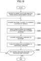
- a log of the driving operation of the vehicle may be recorded in association with the position information of the drivable route.
- the log includes information on the operations of the flashers 24R and 24L, vehicle speed, and temporary stop, for example.
- the generator of the route basic information may add additional guidance to each waypoint while referring to the log. This provides the route basic information shown in FIG. 6A.
Landscapes
- Engineering & Computer Science (AREA)
- Physics & Mathematics (AREA)
- Radar, Positioning & Navigation (AREA)
- Remote Sensing (AREA)
- General Physics & Mathematics (AREA)
- Automation & Control Theory (AREA)
- Aviation & Aerospace Engineering (AREA)
- Atmospheric Sciences (AREA)
- Life Sciences & Earth Sciences (AREA)
- Electromagnetism (AREA)
- Multimedia (AREA)
- Computer Vision & Pattern Recognition (AREA)
- Geometry (AREA)
- Human Computer Interaction (AREA)
- Transportation (AREA)
- Mechanical Engineering (AREA)
- Traffic Control Systems (AREA)
- Navigation (AREA)
- Control Of Driving Devices And Active Controlling Of Vehicle (AREA)
- Control Of Position, Course, Altitude, Or Attitude Of Moving Bodies (AREA)
Abstract
Description
- The present disclosure relates to a travel route generating device, a travel route generating method, and an autonomous driving system.
-
Patent Literature 1 proposes a system including a vehicle that travels within a predetermined area and a control device that receives a vehicle dispatch request from a user and moves the vehicle toward a pick-up location desired by the user. The drivable routes are determined in the area in advance, and upon receiving the dispatch command from the control device, the vehicle moves according to the dispatch command to the pick-up location desired by the user. The dispatch command may specify not only the pick-up location but also a route that the user desires to travel from the pick-up location to the drop-off location (destination). - Patent Literature 1:
WO2019/124534A - Upon receiving a planned route, which is a route to be traveled, an autonomous vehicle controls a driving device (e.g., an electric motor) and a steering mechanism so as to travel along the planned route while monitoring the current location of the vehicle with an external sensor, such as LiDAR (light detection and ranging). It is desirable that the planned route required for such traveling is generated by simple processing.
-
- (1) A travel route generating device proposed in this disclosure includes a storage device in which route basic information is stored in advance, the route basic information including waypoints arranged along a drivable route previously defined in a predetermined area, and a computing device for generating planned route information indicating a route to be traveled by a vehicle in response to a movement request to the vehicle. The computing device extracts some of the waypoints included in the route basic information as the planned route information, where the some of the waypoints being arranged from a traveling start position to a traveling end position according to the movement request. This device enables to relatively easily generate the planned route.
- (2) The travel route generating device of (1) may further include a communication device for transmitting the planned route information to the vehicle. This eliminates the need to perform route search in the vehicle, thereby reducing the computational load on the vehicle.
- (3) In the travel route generating device of (1), the route basic information may include additional guidance in association with at least one of the waypoints included in the route basic information, where the additional guidance indicates a predetermined operation to be performed by the vehicle or a predetermined operation that the vehicle is allowed to perform. In this manner, the additional guidance included in the planned route can help control of the autonomous vehicle.
- (4) In the travel route generating device of (3), the additional guidance may be information for guiding the vehicle to at least one of operations including a temporary stop of the vehicle, overtaking a vehicle travelling ahead, processing related to an arbitration with another vehicle at an intersection, and flashing of a flasher. In this manner, the additional guidance included in the planned route can help a temporary stop of the vehicle, overtaking a vehicle travelling ahead, processing related to an arbitration with another vehicle at an intersection, or flashing of a flasher.
- (5) In the travel route generating device of (1), each of the waypoints included in the route basic information is associated with a coordinate value in a coordinate system defined in the predetermined area and a coordinate value of a world geodetic system. This can specify the pick-up location and the drop-off location desired by the user by the coordinate values of the world geodetic system.
- (6) In the travel route generating device of (1), the route basic information may include first basic information and second basic information, where the first basic information defines a plurality of links indicating the drivable route and a plurality of nodes, which are ends of the plurality of links, and the second basic information associates the plurality of links with the waypoints arranged along the drivable route. The computing device may search for a link from the traveling start position to the traveling end position using the first basic information and refer to the second basic information so as to acquire a waypoint corresponding to the link obtained by the search as the planned route information. This serves to reduce the computational load required for the route search.
- (7) In the travel route generating device of (1), the route basic information may include first basic information and second basic information, where the first basic information indicates the drivable route previously defined in the predetermined area, and the second basic information associates a route specified by the first basic information with a waypoint. The computing device may search for a route from the traveling start position to the traveling end position by using the first basic information and refer to the second basic information so as to acquire a waypoint corresponding to the route obtained by the search as the planned route information. By simplifying the first basic information, the computational load required for the route search can be reduced.
- (8) In the travel route generating device of (1), the drivable route may have an annular shape. In this manner, the vehicle can reach the traveling end position by being moved in the traveling direction regardless of the positional relationship between the traveling start position and the traveling end position.
- (9) In the travel route generating device of (1), the route defined by the planned route information may continue from the traveling start position according to the movement request to the traveling end position according to the movement request. The route defined by the planned route information may include a first partial route and a second partial route between the traveling start position and the traveling end position. The computing device may divide the waypoints extracted as the route defined by the planned route information into the waypoints corresponding to the first partial route and the waypoints corresponding to the second partial route.
- (10) In the travel route generating device of (9), the route defined by the planned route information may include an intersection, the first partial route may include one of two routes intersecting with each other at the intersection, and the second partial route may include the other of the two routes intersecting with each other at the intersection. This helps the autonomous vehicle to properly drive through the intersection.
- (11) An autonomous driving system includes the travel route generating device and the vehicle of (1), where the vehicle may include a driving mechanism, a steering mechanism, and a control device that controls the driving mechanism and the steering mechanism so that the vehicle travels along the route defined by the planned route information. The travel route generating device may include a communication device that transmits the planned route information to the vehicle. This eliminates the need to perform route search in the vehicle, thereby reducing the computational load on the vehicle.
- (12) In the autonomous driving system of (11), it may be determined whether the vehicle is on the drivable route. The travel route generating device may not need to transmit the planned route information to the vehicle in a case where the vehicle is not on the drivable route.
- (13) In the autonomous driving system of (11), the movement request to the vehicle may be a request for at least one of a movement from a current location of the vehicle to a pick-up location desired by a user, a movement from the pick-up location desired by the user to a drop-off location desired by the user, or a movement from the current location of the vehicle to a forwarding location.
- (14) In the autonomous driving system of (11), the vehicle may include an external sensor and a storage device, where the external sensor outputs surrounding information indicating a position of an object around the vehicle, and the storage device stores map information indicating a position of an object in the predetermined area. The control device of the vehicle may include a location estimating unit that matches the surrounding information with the map information so as to estimate a location of the vehicle. The map information may be transmitted to the vehicle at a timing different from the planned route information. This allows map information having a large amount of data to be safely transmitted to the vehicle.
- (15) In the autonomous driving system of (11), the vehicle may include an external sensor and a storage device, where the external sensor outputs surrounding information indicating a position of an object around the vehicle, and the storage device stores map information indicating a position of an object in the predetermined area. The control device of the vehicle may include a location estimating unit that matches the surrounding information with the map information so as to estimate a location of the vehicle. The map information may be transmitted to the vehicle using communication means different from communication means for receiving the planned route information. This allows map information having a large amount of data to be safely transmitted to the vehicle.
- (16) A travel route generating method proposed in this disclosure is a method for generating a planned route indicating a route to be traveled by a vehicle in a predetermined area. The method includes the steps of acquiring a traveling start position and a traveling end position according to a movement request to the vehicle and referring to route basic information that includes waypoints arranged along a predetermined drivable route in the predetermined area and is stored in a storage device so as to extract some of the waypoints that are included in the route basic information as the planned route information, where the some of the waypoints are arranged from the traveling start position to the traveling end position. This method enables to relatively easily generate the planned route.
-
-
FIG. 1 is a block diagram showing a configuration of an autonomous driving system proposed in the present disclosure; -
FIG. 2 is a block diagram showing a configuration of an autonomous vehicle; -
FIG. 3 is a sequence diagram showing an example of processing executed by the autonomous vehicle, a vehicle management device, and a mobile terminal; -
FIG. 4 is a block diagram showing functions of the vehicle management device; -
FIG. 5A is a diagram for explaining an example of route basic information; -
FIG. 5B is a diagram showing an example of waypoints constituting the route basic information; -
FIG. 6 is a diagram showing planned route information extracted from the route basic information; -
FIG 7 is a flow chart showing an example of processing executed by a transportation managing unit, a forwarding managing unit, and a planned route generating unit of the management device; -
FIG. 8 is a flow chart showing an example of processing executed by the planned route generating unit; -
FIG 9 is a diagram for explaining the route basic information; -
FIG. 10 is a diagram for explaining additional guidance included in the route basic information; -
FIG. 11 is a diagram for explaining additional guidance included in the route basic information; -
FIG. 12 is a diagram for explaining additional guidance included in the route basic information; -
FIG. 13 is a diagram for explaining additional guidance included in the route basic information; -
FIG. 14 is a diagram for explaining additional guidance included in the route basic information; -
FIG. 15A is a diagram showing a modification of the route basic information and explaining first basic information including the route basic information according to the modification; -
FIG. 15B is a diagram showing a modification of the route basic information and explaining second basic information including the route basic information according to the modification; -
FIG. 16 is a diagram for explaining an example of dividing the planned route from a traveling start position to a traveling end position into a first partial route and a second partial route; -
FIG. 17 is a block diagram showing functions of a control device of the autonomous vehicle; -
FIG. 18 is a flow chart showing an example of processing executed by the control device of the autonomous vehicle; and -
FIG. 19 is a diagram for explaining processing for generating the route basic information. - Embodiment of the present invention will be described.
FIG. 1 is a block diagram showing anautonomous driving system 1, which is an example of an embodiment of the present invention. - As shown in
FIG. 1 , theautonomous driving system 1 includes avehicle management device 70 and a plurality ofautonomous vehicles 10. Thevehicle management device 70 is connected to theautonomous vehicles 10 via an information communication network N. Thevehicle management device 70 is also connected to amobile terminal 90, which is used for requesting the use of theautonomous vehicle 10, via the information communication network N. The information communication network N includes the Internet, a mobile telephone network, WAN (Wide Area Network), LAN (Local Area Network), and a dedicated line, for example. In the following, thevehicle management device 70 is simply referred to as amanagement device 70, and theautonomous vehicle 10 is simply referred to as avehicle 10. - The
autonomous driving system 1 is a system used in a predetermined area B (seeFIG. 5A ). The predetermined area B is a limited range such as an amusement park, a golf course, an event hall, and a tourist spot. The predetermined area B may be an area where general vehicles are restricted. In still another example, the predetermined area B may be a public road on which a travel route is set in advance. In this case, general vehicles may be allowed to travel in the travel route. Thevehicle 10 travels along a predetermined drivable route within the area B under the control of themanagement device 70. For example, themanagement device 70 transmits, to thevehicle 10, a route to a pick-up location desired by the user and a route to a drop-off location (destination) desired by the user. Thevehicle 10 travels along the route received from themanagement device 70. In the following, the "predetermined area" is referred to as a "vehicle operation area." -
FIG. 2 is a block diagram showing a configuration of theautonomous vehicle 10. Thevehicle 10 has acontrol device 11 including acomputing device 12 and astorage device 13. Thecomputing device 12 includes a CPU (Central Processing Unit), a GPU (Graphics Processing Unit), and an FPGA (Field Programmable Gate Array), for example. Thecomputing device 12 executes a program stored in thestorage device 13 and controls adriving mechanism 21 and asteering mechanism 23 that are described later. Thestorage device 13 includes, for example, a RAM (Random Access Memory) and a ROM (Read Only Memory). Thecontrol device 11 may include a plurality of devices (each including a computing device and a storage device) connected to each other via networks (e.g., controller area network (CAN)) mounted on thevehicle 10. In addition to the program, thestorage device 13 stores data for theautonomous vehicle 10 to estimate its location (e.g., point cloud data), for example. When thevehicle 10 is traveling, route information received from themanagement device 70 is stored in thestorage device 13. - As shown in
FIG. 2 , thevehicle 10 includes adriving mechanism 21, abraking mechanism 22, asteering mechanism 23, and left andright flashers driving mechanism 21 includes an electric motor as a driving source of wheels, for example. In this case, thevehicle 10 includes a battery that stores power to be supplied to the electric motor. The driving source may be an engine. Thedriving mechanism 21 may include a transmission or a reduction gear on a power transmission path from the driving source to the wheels. Thebraking mechanism 22 applies a braking force to the wheels and includes a brake device and a control valve connected to the brake device via hydraulics. Thesteering mechanism 23 steers the front wheels, for example, and includes a steering shaft, a tie rod connecting the steering shaft to the wheels, and an actuator for rotating the steering shaft. Theflasher 24R is a direction indicator for right turn and theflasher 24L is a direction indicator for left turn. Thevehicle 10 is a vehicle in which a plurality of users can be seated, for example, but may be a vehicle for one person. - As shown in
FIG. 2 , thevehicle 10 has anexternal sensor group 30 for outputting surrounding information indicating positions of objects in the surrounding of thevehicle 10. Theexternal sensor group 30 includes, for example, a LiDAR (light detection and ranging) 31 and afront camera 32. Theexternal sensor group 30 may include arear camera 33. Theexternal sensor group 30 may include an ultrasonic sonar and a millimeter wave radar, for example. Thevehicle 10 also includes aGNSS receiver 34. TheGNSS receiver 34 receives radio waves from GNSS satellites (e.g., GPS satellites) and measures the position of thevehicle 10 based on the received radio waves. Thevehicle 10 may have aload sensor 35 for detecting loads acting on the seat. Thevehicle 10 can detect whether the user is seated based on the output of theload sensor 35. Thevehicle 10 may have a camera that captures the interior of thevehicle 10 instead of theload sensor 35. Thevehicle 10 may determine whether the user is seated in thevehicle 10 based on an image captured by the camera. Thecommunication device 36 is a wireless communication module for communicating with thevehicle management device 70 via the information communication network N. Thevehicle 10 may include adisplay device 37 and aninput device 38. Thedisplay device 37 is a liquid crystal display or an organic EL display, for example. Theinput device 38 is a touch sensor provided on thedisplay device 37, for example. Thevehicle 10 may have buttons and switches as theinput device 38. - As shown in
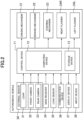
FIG. 1 , thevehicle management device 70 includes acomputing device 71, astorage device 72, and acommunication device 73. Thecomputing device 71 includes a CPU (Central Processing Unit), a GPU (Graphics Processing Unit), and an FPGA (Field Programmable Gate Array), for example. Thecomputing device 71 executes a program stored in thestorage device 72, and, in response to a dispatch request from themobile terminal 90 of the user, for example, searches and generates a route to a pick-up location desired by the user and a route to a drop-off location desired by the user. Thestorage device 72 includes an HDD (hard disk drive), a RAM, and a ROM, for example. Thestorage device 72 stores information to be the basis of a route to be traveled by the vehicle 10 (route basic information to be described later). Thecommunication device 73 is a communication module for communicating with themobile terminal 90 of the user and theautonomous vehicle 10 via the information communication network N. Themanagement device 70 may further include an input device (keyboard) for an administrator to input commands to themanagement device 70 and a display device for outputting a result of processing executed by thecomputing device 71, for example. - As shown in
FIG. 1 , themobile terminal 90 includes acomputing device 91, astorage device 92, adisplay device 93, aninput device 94, aGNSS receiver 95, and acommunication device 96. Thecomputing device 91 includes a CPU and executes a program stored in thestorage device 92, thereby executing the processing required by the user, for example. Thestorage device 92 includes a RAM and a ROM, for example. For example, thedisplay device 93 is a liquid crystal display or an organic EL display, and theinput device 94 is a touch sensor, a keyboard, and a button to be provided to thedisplay device 93. Thecommunication device 96 is a wireless communication module for communicating with thevehicle management device 70 via the information communication network N. Thecommunication device 96 may communicate by wireless or wired. Themobile terminal 90 is a smart phone, for example, but may not be necessarily limited thereto. -
FIG. 3 is a sequence diagram showing an example of processing executed by theautonomous vehicle 10, thevehicle management device 70, and themobile terminal 90 when the user wishes to move within the vehicle operation area B. - The
vehicle 10 transmits information on the current location and the status of thevehicle 10 to the vehicle management device 70 (S101). The information on the state of thevehicle 10 includes whether thevehicle 10 is transporting a user (or waiting), for example. The information on the state of thevehicle 10 may include the remaining amount of the battery mounted on thevehicle 10 and whether there are any anomalies, for example. The information on the current location and the state of thevehicle 10 may be transmitted tomanagement device 70 at regular time intervals while thecontrol device 11 of thevehicle 10 is activated. - The
management device 70 receives a dispatch and transportation request from themobile terminal 90 of the user (S102). - The "dispatch" is to select one of the
vehicles 10 in theautonomous driving system 1 and to move the selectedvehicle 10 to the pick-up location desired by the user. In the following, the location where the user wishes to get in the vehicle is referred to as a "desired pick-up location." An example of the desired pick-up location is the current location of the user. Another example of the desired pick-up location may be a location designated through themobile terminal 90, for example. The "transportation" means that thevehicle 10 in which the user gets at the pick-up location moves to a location where the use wishes to get off (destination). In the following, such a location to get off the vehicle is referred to as a "desired drop-off location." The dispatch and transportation request sent by themobile terminal 90 to themanagement device 70 includes information indicating the desired pick-up location. The dispatch and transportation request may include information on the number of persons wishing to ride, a desired drop-off location (destination), and a desired time to ride, for example. - Upon receiving the dispatch and transportation request, the
management device 70 searches for a vehicle to be directed to the desired pick-up location among from thevehicles 10 that theautonomous driving system 1 has (S103). For example, themanagement device 70 selects avehicle 10 closest to the desired pick-up location. Themanagement device 70 may select a vehicle to be directed to the desired pick-up location based on the number of persons wishing to ride and the number of persons that can be seated in thevehicle 10, for example. - The
management device 70 searches for a route to be traveled by thevehicle 10 from the waiting position of the vehicle 10 (i.e., the current location of the vehicle 10) to the desired pick-up location, and transmits information indicating such a route to the vehicle 10 (S104). In the following, the route to be traveled by thevehicle 10 is referred to as a "planned route", and the "information indicating the planned route" is referred to as "planned route information." In theautonomous driving system 1, the planned route information is a set of waypoints (W shown inFIG. 6 ) arranged along the planned route. The waypoint includes position information (coordinate value) within the vehicle operation area B. The generation of waypoints and planned route information will be described in detail later. - When not only the dispatch request but also the transportation request is received from the
mobile terminal 90, i.e., the information on the desired pick-up location and information on the desired drop-off location are received from themobile terminal 90, themanagement device 70 may search a planned route from the waiting location (current location) of thevehicle 10 to the desired pick-up location and a planned route from the desired pick-up location to the desired drop-off location, and transmit such information to thevehicle 10 in S104. - Upon receiving the planned route information, the
vehicle 10 transmits a start notification indicating that thevehicle 10 has started to the management device 70 (S105), and starts traveling from the waiting location to the desired pick-up location (S106). Thevehicle 10 travels in this manner when thevehicle 10 tracks the waypoints, which are included in the planned route information and continue from the waiting location to the desired pick-up location (i.e., to move toward the waypoint close to the current location). Upon arriving at the desired pick-up location, thevehicle 10 transmits a notification of the arrival to the management device 70 (S107). Themanagement device 70 transmits the arrival notification of thevehicle 10 to themobile terminal 90 of the user (S108). Thevehicle 10 may directly transmit the arrival notification to themobile terminal 90. - When the user gets in the
vehicle 10 and thevehicle 10 detects that the user is seated through the load sensor 35 (or camera), thevehicle 10 transmits a pick-up completion notification to the management device 70 (S109). When thevehicle 10 has already received the planned route information on the route from the desired pick-up location to the desired drop-off location (destination) from themanagement device 70 and receives a start instruction from the user (S110), thevehicle 10 transmits the start notification indicating that thevehicle 10 has started to management device 70 (Sill), and starts traveling from the desired pick-up location to the desired drop-off location (S112). The start instruction of the user is entered in thecontrol device 11 when the user performs a predetermined operation on theinput device 38 provided in thevehicle 10, for example. Thevehicle 10 travels when thevehicle 10 follows the waypoints included in the planned route information continuing from the desired pick-up location to the desired drop-off location in order. - Upon arriving at the desired drop-off location, the
vehicle 10 transmits such notification to the management device 70 (S113). Themanagement device 70 transmits the arrival notification to the mobile terminal 90 (S114). Themanagement device 70 may transmit charges required for the transportation service by thevehicle 10 to themobile terminal 90 as an arrival notification. Upon receiving a drop-off completion notification from the mobile terminal 90 (S115), themanagement device 70 transmits a drop-off confirmation request to the vehicle 10 (S116). Upon receiving the drop-off confirmation request, thevehicle 10 determines whether all the users have left the vehicle based on the output of theload sensor 35. Upon confirming that all the users have left, thevehicle 10 transmits a waiting notification to themanagement device 70 to notify that thevehicle 10 has transitioned to the waiting state (S117). The waiting state indicates that thevehicle 10 remains at a certain position until a next planned route is received, for example. - As shown in
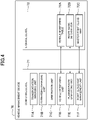
FIG. 4 , thecomputing device 71 of thevehicle management device 70 functionally includes atransportation managing unit 71A, avehicle monitoring unit 71D, and a plannedroute generating unit 71E so as to operate themanagement device 70 as described above. Thecomputing device 71 includes aforwarding managing unit 71B and an arbitration unit 71C. These functions are implemented when thecomputing device 71 executes programs stored in thestorage device 72. - The
vehicle 10 transmits information on the current location and the status of thevehicle 10 to thevehicle management device 70. As described above, the information on the state of thevehicle 10 may include whether thevehicle 10 is transporting a user (or waiting), the remaining amount of the battery, and whether there are any anomalies, for example. Such information is transmitted at predetermined time intervals. Thevehicle monitoring unit 71D stores the received information on thevehicle 10 in a vehicle monitoring table 72A stored in thestorage device 72. Thevehicle monitoring unit 71D updates the vehicle monitoring table 72A whenever new information for each of thevehicles 10 is received. - The
vehicle monitoring unit 71D may determine whether thevehicle 10 is available for transportation of a user based on the current location of thevehicle 10. For example, thevehicle monitoring unit 71D may determine whether thevehicle 10 is on a drivable route defined in the vehicle operation area B. If thevehicle 10 is not on a drivable route, that is, if the current location of thevehicle 10 is away from the drivable route defined in the vehicle operation area B by more than a predetermined threshold value, thevehicle monitoring unit 71D may determine that thevehicle 10 is not available and record such information in the vehicle monitoring table. - When the
management device 70 receives a movement request (dispatch request and transportation request) for thevehicle 10 from the user, thetransportation managing unit 71A moves thevehicle 10 in response to such a movement request. Thetransportation managing unit 71A selects avehicle 10 to be directed to the desired pick-up location of the user. Thetransportation managing unit 71A may exclude avehicle 10 that is away from the drivable route defined in the vehicle operation area (i.e., avehicle 10 that is determined to be unavailable by thevehicle monitoring unit 71D) from the selection target. For example, thetransportation managing unit 71A may exclude thevehicle 10 that is recorded in the vehicle monitoring table as being unavailable from the selection targets. - The
transportation managing unit 71A transmits a movement command to the selectedvehicle 10 to move from the current location of thevehicle 10 toward the desired pick-up location. Further, thetransportation managing unit 71A transmits a movement command to thevehicle 10 to move from the desired pick-up location toward the desired drop-off location. Thetransportation managing unit 71A may transmit the planned route information generated by a plannedroute generating unit 71E, which will be described later, to thevehicle 10 as a movement command. - The
forwarding managing unit 71B transmits a command (forwarding command) to thevehicle 10 to move toward the forwarding location predetermined in the vehicle operation area B. For example, the forwarding location is a garage in which thevehicle 10 is stored. Another example of the forwarding location may be a charging station for charging the battery of thevehicle 10. For example, theforwarding managing unit 71B may transmit a forwarding command to thevehicle 10 when a predetermined time comes or when the remaining battery capacity falls below the threshold value. In the example of themanagement device 70, theforwarding managing unit 71B transmits the planned route information generated by the plannedroute generating unit 71E to thevehicle 10 as a forwarding command. - When the
management device 70 receives a request for moving thevehicle 10, the plannedroute generating unit 71E generates information on a route to be traveled by the vehicle 10 (planned route), that is, planned route information. As described above, one of the movement requests for thevehicle 10 is a movement from the current location (waiting location) of thevehicle 10 to the desired pick-up location of the user (i.e., dispatch). Another movement request for thevehicle 10 is a movement from the desired pick-up location to the desired drop-off location (destination) (i.e., transportation). Yet another movement request for thevehicle 10 is a movement of thevehicle 10 from the current location of thevehicle 10 to the forwarding position (i.e., forwarding). Thestorage device 72 stores the route basic information in advance. The route basic information indicates a route that thevehicle 10 can travel and is predetermined in the vehicle operation area B. The plannedroute generating unit 71E extracts a part of the route basic information as the planned route information. -
FIGs. 5A and5B are diagrams for explaining the route basic information. As shown inFIG. 5A , the route basic information is composed of waypoints W that are arranged along the routes L1 and L2 on which thevehicles 10 can travel. The waypoints W may be arranged at approximately constant intervals (e.g., one or several meters apart) along the drivable routes L1 and L2. The route basic information has waypoints for all the drivable routes defined in the vehicle operation area B. As shown inFIG. 5B , each waypoint includes position data of positions (points) on the drivable route. Specifically, each waypoint has coordinate values (X, Y, Z) in the coordinate system defined in the vehicle operation area B. - The route basic information is different from the information that the
vehicle 10 uses to estimate its current location, i.e. map information (information indicating objects in the vehicle operation area B). In the example of theautonomous driving system 1, thevehicle 10 uses a point cloud map as such map information. The point cloud map is stored in thestorage device 13 of thevehicle 10. - When the
management device 70 receives a movement request for thevehicle 10, the plannedroute generating unit 71E extracts some of the waypoints included in the route basic information and uses the extracted waypoints as planned route information. For example, as shown inFIGs. 6 and5B , the plannedroute generating unit 71E extracts waypoints arranged from waypoint (i) representing the traveling start position to waypoint (k) representing the traveling end position as the planned route information. Themanagement device 70 transmits the planned route information extracted in this manner to thevehicle 10 in the processing of thetransportation managing unit 71A and theforwarding managing unit 71B. - The drivable route predetermined in the vehicle operation area B desirably has an annular shape. That is, it is desirable that the drivable route is defined so that there is no dead end. In other words, it is desirable that all the waypoints defined in the route basic information have adjacent waypoints within a predetermined range in the direction in which the
vehicle 10 moves forward. For example, as shown inFIG. 5A , the waypoint (1) at the top of the route basic information inFIG. 5B is located in the direction in which thevehicle 10 moves forward with respect to the waypoint (N) at the bottom of the route basic information, and the distance between the waypoint (1) and the waypoint (N) is the same as the distance between the other waypoints. If the drivable route has a single road R1, as shown inFIG. 9 for example, two rows L5 and L6 of waypoints connected at the ends may be defined as the road R1. This allows thevehicle 10 to reach the traveling end position by moving forward regardless of where the traveling start position and the traveling end position are on the drivable route. - As described above, the planned
route generating unit 71E is provided in thevehicle management device 70 in theautonomous driving system 1. This reduces the processing load to be performed in thevehicle 10. Thevehicle management device 70 corresponds to the route generating device in the claims. The plannedroute generating unit 71E may be provided not in thevehicle management device 70 but in thecontrol unit 11 of thevehicle 10. -
FIG. 7 is a flow chart showing an example of processing executed by themanagement device 70.FIG. 7 shows examples of processing executed by thetransportation managing unit 71A, theforwarding managing unit 71B, and the plannedroute generating unit 71E. - When the
management device 70 receives a vehicle dispatch request from themobile terminal 90, thetransportation managing unit 71A searches for avehicle 10 waiting at a location closest to the user (mobile terminal 90) (S201). Thetransportation managing unit 71A refers to a current location of eachvehicle 10 recorded in the vehicle monitoring table 72A, and searches for thevehicle 10 closest to the user (mobile terminal 90) based on the position information (latitude, longitude, altitude) sent from themobile terminal 90. Subsequently, thetransportation managing unit 71A determines whether the searchedvehicle 10 is available (S202). If the searchedvehicle 10 is available, thetransportation managing unit 71A selects such avehicle 10 as a vehicle to be directed to the pick-up location of the user. On the other hand, if the searchedvehicle 10 is not available, thetransportation managing unit 71A executes the search process of S201 again. - Next, the
transportation managing unit 71A determines whether the information indicating the desired drop-off location has been received in addition to the information indicating the desired pick-up location, in other words, whether both the desired pick-up location and the desired drop-off location have been designated (S203). If themanagement device 70 has received the desired pick-up location and drop-off location, the plannedroute generating unit 71E generates planned route information indicating the route from the current location of thevehicle 10 selected in S201 to the desired pick-up location (S204) and also generates planned route information indicating the route from the desired pick-up location to the desired drop-off location (S205). Thetransportation managing unit 71A transmits the generated two pieces of planned route information to the vehicle 10 (S206). - In S203, if the
management device 70 has received only the desired pick-up location and not received the desired drop-off location, the plannedroute generating unit 71E generates planned route information indicating the route from the current location of thevehicle 10 selected in S201 to the desired pick-up location (S210), and thetransportation managing unit 71A transmits the planned route information generated in S207 to thevehicle 10 as a dispatch command (S211). - Subsequently, the
transportation managing unit 71A determines whether the desired drop-off location has been received (S212). Upon receiving the desired drop-off location, the plannedroute generating unit 71E generates planned route information indicating the route from the desired pick-up location to the desired drop-off location (S213). Thetransportation managing unit 71A transmits the planned route information generated in S213 to thevehicle 10 as a transportation command (S214). - The
forwarding managing unit 71B determines whether to issue a forwarding command for the vehicle 10 (S207). Specifically, theforwarding managing unit 71B determines whether the current time has reached the time at which thevehicle 10 is returned to the forwarding location or whether the remaining battery level is lower than the threshold value. If it is determined that a forwarding command is to be issued, the plannedroute generating unit 71E generates planned route information indicating the route from the current location of thevehicle 10 to the forwarding location (S208). Theforwarding managing unit 71B transmits the generated planned route information to thevehicle 10 as a forwarding command (S209). Theforwarding managing unit 71B may execute processing of S209 to S207 for each of thevehicles 10 included in theautonomous driving system 1. The above described is examples of the processing executed by thetransportation managing unit 71A, theforwarding managing unit 71B, and the plannedroute generating unit 71E. -
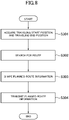
FIG. 8 is a flow chart showing an example of processing executed by the plannedroute generating unit 71E. The processing is executed in S204, S205, S208, S210, and S213 shown inFIG. 7 , for example. - The planned
route generating unit 71E first acquires a traveling start position and a traveling end position (S301). - For dispatching a vehicle, the traveling start position is the waiting location (current location) of the
vehicle 10 selected in the processing of thetransportation managing unit 71A, and the traveling end position is the desired pick-up location. The plannedroute generating unit 71E refers to the vehicle monitoring table 72A, for example, and acquires the current location (i.e., the traveling start position) of thevehicle 10 selected by thetransportation managing unit 71A. In this case, the traveling start position is represented by the values (X, Y, Z) in the coordinate system in the vehicle operation area B. The plannedroute generating unit 71E refers to the route basic information shown inFIG. 5B , and acquires the waypoint corresponding to the traveling start position (waypoint closest to the traveling start position). - The desired pick-up location is the current location of the user, for example. The
management device 70 receives the current location (latitude, longitude, altitude) obtained by theGNSS receiver 95 of themobile terminal 90 together with a dispatch request. As shown inFIG. 5B , the route basic information includes values in the world geodetic system (latitude, longitude, altitude) as the position information of the respective waypoints. Themanagement device 70 acquires the waypoint corresponding to the position information of the world geodetic system received from themobile terminal 90 as the traveling end position. Alternatively, thedisplay device 93 of themobile terminal 90 may display map information including a map of the vehicle operation area B and coordinate values of respective points on the map. Themobile terminal 90 may transmit the coordinate values (X, Y, Z) of the position selected by the user on the map displayed on thedisplay device 93 to themanagement device 70 as the desired pick-up location. - In the case of transportation, the traveling start position of the
vehicle 10 is the desired pick-up location, and the traveling end position of thevehicle 10 is the desired drop-off location. The desired pick-up location can be acquired by the same processing as in the case of dispatching the vehicle. The desired drop-off location may be specified on themobile terminal 90 by the user. For example, themobile terminal 90 may transmit the coordinate values (X, Y, Z) of the position specified by the user on the map displayed on thedisplay device 93 to themanagement device 70 as the desired drop-off location. Alternatively, themobile terminal 90 may transmit the coordinates (X, Y, Z) of the facility selected by the user in the vehicle operation area B to themanagement device 70 as the desired drop-off location. The desired drop-off location may be specified by thevehicle 10 instead of themobile terminal 90. For example, thevehicle 10 may transmit the coordinate values (X, Y, Z) of the position specified by the user on the map displayed on thedisplay device 37 to themanagement device 70 as the desired drop-off location. - In the case of forwarding a vehicle, the traveling start position of the
vehicle 10 is the current location of thevehicle 10, and the traveling end position of thevehicle 10 is the forwarding location. - The planned
route generating unit 71E searches for a route from the waypoint corresponding to the traveling start position to the waypoint corresponding to the traveling end position (S302). As shown inFIGs. 5A and5B , this processing extracts a plurality of consecutive waypoints from the waypoint corresponding to the traveling start position to the waypoint corresponding to the traveling end position (i.e., planned route information). - Dijkstra, Bellman-Ford, and A-star algorithms can be used for route search. When these methods are used, each waypoint may be used as a node, and distances between the waypoints may be defined as a cost. In this way, the shortest route in distance connecting the traveling start position and the traveling end position is obtained.
- In another example, each waypoint may be used as a node, and the time required to move between waypoints may be defined as a cost. In this way, the shortest route in time connecting the traveling start position and the traveling end position is obtained. If it takes a lot of time to pass an intersection, a large cost may be defined between the waypoints corresponding to the intersection. Further, if it takes a lot of time to pass a plurality of uphills, a large cost may be defined between the waypoints corresponding to the uphills.
- The planned
route generating unit 71E may shape the planned route information obtained in S302 according to the state and the specification of the vehicle 10 (selected by thetransportation managing unit 71A) using the planned route information (S303). As shown inFIG. 5B , the route basic information includes not only position information but also additional guidance, such as "vehicle speed" and "turn flag", for each waypoint. For example, "vehicle speed" shows the vehicle speed that thevehicle 10 has when passing through the waypoint, and "turn flag" shows the control for right turn (or left turn) to thevehicle 10 when passing through the waypoint (e.g., flashing offlashers vehicle 10 may not have a function of executing such a control based on the "turn flag." In this case, the plannedroute generating unit 71E may eliminate the "turn flag" from the planned route information generated in S302. Thevehicle 10 may not have a function of executing control based on the "vehicle speed." In this case, the plannedroute generating unit 71E may eliminate the "vehicle speed" from the planned route information generated in S302. That is, the plannedroute generating unit 71E may shape the planned route information obtained in S302 according to thevehicles 10 selected by thetransportation managing unit 71A, such as eliminating unnecessary additional guidance. The additional guidance will be described in detail later. Finally, themanagement device 70 transmits the planned route information shaped in S303 to the vehicle 10 (S304). The above described is examples of the processing executed by the plannedroute generating unit 71E. - As described above, the route basic information may include additional guidance in association with the waypoint indicating the position information. The additional guidance is different from the position information of the waypoint. The additional guidance is information indicating an operation to be performed by the
vehicle 10 arriving at the waypoint corresponding to such additional guidance, or an allowable operation for thevehicle 10 arriving at the waypoint corresponding to such additional guidance. The additional guidance may rely on traffic rules. - As shown in
FIG. 5B , an example of additional guidance is vehicle speed. When thevehicle 10 is traveling along the waypoints representing the planned route, the control device 11 (travelingcontrol unit 12B, seeFIG. 17 ) of thevehicle 10 controls thedriving mechanism 21 and thebraking mechanism 22 so as to travel at a speed lower than the speed associated with the respective waypoints. - As shown in
FIG. 5B , another example of the additional guidance is a turn flag.FIG. 10 is a diagram for explaining the turn flag, in which a black circle indicates a waypoint to which "turn flag: OFF" (0 inFIG. 5B ) is assigned, and a white circle indicates a waypoint to which "turn flag: ON" (1 inFIG. 5B ) is assigned. When thevehicle 10 reaches a waypoint at which the turn flag is ON (waypoint W1 inFIG. 10 ), the control device 11 (travelingcontrol unit 12B, seeFIG. 17 ) of thevehicle 10 determines whether to blink theflashers vehicle 10 arrives) among the waypoints included in the planned route information. - In the example of
FIG. 10 , when thevehicle 10 reaches the waypoint W1, thecontrol device 11 determines whether to blink theright flasher 24R or theleft flasher 24L or not to blink both of theflashers vehicle 10. For example, if the waypoints closer to the waypoint W1 are W2 to W5, their positions are shifted to the right with respect to the traveling direction of thevehicle 10. As such, thecontrol device 11 determines that thevehicle 10 turns right, and thus flashes theright flasher 24R. On the other hand, if the waypoints closer to the waypoint W1 are W2, W3, and W8 to W10, their positions are in the traveling direction of thevehicle 10. As such, thecontrol device 11 determines that thevehicle 10 travels straight, and thus does not blink the left andright flashers - As shown in
FIG. 5B , still another example of additional guidance is a traffic light stop line flag.FIG. 11 is a diagram for explaining the traffic light stop line flag, in which a black circle indicates a waypoint to which "traffic light stop line flag: OFF" (0 inFIG. 5B ) is assigned, and a white circle indicates a waypoint to which "traffic light stop line flag: ON" (1 inFIG. 5B ) is assigned. When thevehicle 10 reaches the waypoint where the traffic light stop line flag is ON (the waypoint where reference numeral W1 is given inFIG. 11 ), thecontrol device 11 of the vehicle 10 (travelingcontrol unit 12B, seeFIG. 17 ) detects a color of the traffic signal based on an image acquired through thefront camera 32, and controls thebraking mechanism 22 to stop thevehicle 10 if the traffic light is red or yellow. Subsequently, thecontrol device 11 determines whether the color of the traffic light has changed to blue based on an image acquired through thefront camera 32, and controls thedriving mechanism 21 to start thevehicle 10 when the color of the traffic light is changed to blue. - The control device 11 (traveling
control unit 12B, seeFIG. 17 ) of thevehicle 10 may start the processing described above before the waypoint at which the traffic light stop line flag is ON. That is, thecontrol device 11 may read a plurality of waypoints subsequent to the waypoint corresponding to the current location among the waypoints included in the planned route information. If the waypoint at which the traffic light stop line flag is ON (waypoint W1 inFIG. 11 ) is included in the plurality of waypoints, thecontrol device 11 may detect a color of the traffic light based on an image acquired through thefront camera 32. If the traffic light is red or yellow, thecontrol device 11 controls thebraking mechanism 22 to stop thevehicle 10 at a position corresponding to the waypoint at which the traffic light stop line flag is ON. - As shown in
FIG. 5B , still another example of additional guidance is a temporary stop line flag. When thevehicle 10 reaches the waypoint at which the temporary stop line flag is ON, the control device 11 (travelingcontrol unit 12B, seeFIG. 17 ) of thevehicle 10 controls thebraking mechanism 22 to stop thevehicle 10. Thecontrol device 11 may determine whether there is an obstacle based on an image acquired through thefront camera 32, for example. This determination may continue for several seconds. If no obstacle is detected, thecontrol device 11 may control thedriving mechanism 21 to start thevehicle 10. - The additional guidance may further include a crosswalk stop line flag. When the
vehicle 10 reaches the waypoint at which the crosswalk stop line flag is ON, thecontrol device 11 of thevehicle 10 controls thebraking mechanism 22 to stop thevehicle 10. Thecontrol device 11 may determine whether there is an obstacle (including a person) based on an image acquired through thefront camera 32, for example. This determination may continue for several seconds. If no obstacle is detected, thecontrol device 11 may control thedriving mechanism 21 to start thevehicle 10. - As shown in
FIG. 5B , yet another example of additional guidance is an overtaking enable flag.FIG. 12 is a diagram for explaining the overtaking enable flag, in which a black circle indicates a waypoint to which "overtaking enable flag: OFF" (0 inFIG. 5B )" is assigned, and a white circle indicates a waypoint to which "overtaking enable flag: ON" (1 inFIG. 5B )" is assigned. When thevehicle 10 reaches the waypoint at which the overtake flag is ON, the control device 11 (travelingcontrol unit 12B, seeFIG. 17 ) of thevehicle 10 determines whether there is an obstacle in front of thevehicle 10 based on an image acquired through thefront camera 32. If there is no obstacle, thevehicle 10 travels along the waypoints included in the planning route information. If there is an obstacle K on the route defined by the waypoints, as indicated by an arrow T inFIG. 12 , thevehicle 10 travels in a range away from the waypoints to the right or left and within a predetermined distance from the waypoints. That is, the overtaking enable flag is a guidance for allowing the vehicle to travel at a position away from the waypoint by a predetermined distance. - As shown in
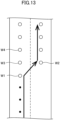
FIG. 5B , yet another example of additional guidance is an overtaking enable flag.FIG. 13 is a diagram for explaining the overtaking enable flag, in which a black circle indicates a waypoint to which "lane change flag: OFF" (0 inFIG. 5B )" is assigned, and a white circle indicates a waypoint to which "lane change flag: ON" (1 inFIG. 5B ) " is assigned. As shown inFIG. 13 , the planned route information is generated such that waypoints (white circles) to which "lane change flag: ON" is assigned and waypoints (white circles) in the adjacent lane (overtaking lane) (e.g., waypoints to which "lane change flag: ON" is assigned) are arranged in two rows in a predetermined section. Unlike the example ofFIG. 13 , the planned route information may be generated such that waypoints (white circles) to which "lane change flag: ON" is assigned and waypoints to which "lane change flag: OFF" is assigned as the waypoints corresponding to the adjacent lane (overtaking lane) may be arranged in two rows. - The control device 11 (traveling
control unit 12B, seeFIG. 17 ) reads a plurality of waypoints subsequent to the waypoint corresponding to the current location. If the waypoint at which the lane change flag is ON (waypoint W1 inFIG. 13 ) is included in the plurality of waypoints, thecontrol device 11 flashes theflasher 24R, and determines if there is another vehicle approaching from the right rear ofvehicle 10 based on the output of the external sensor group 30 (e.g.,rear camera 33,LiDAR 31, millimeter-wave radar). If there is no other vehicle approaching the vehicle, thecontrol device 11 controls thesteering mechanism 23 to move thevehicle 10 toward the waypoint W2 that is shifted to the right with respect to the traveling direction so far. - If it is determined that there is another vehicle approaching the vehicle based on the output of the
external sensor group 30, thecontrol device 11 does not change the lane but moves thevehicle 10 toward the waypoints W3, W4... arranged along the traveling direction so far. The waypoints W3, W4... are provided with "lane change flag: ON", and thus, thecontrol device 11 also determines if there is another vehicle approaching from the right rear of thevehicle 10 at the waypoints W3, W4... similarly to the processing at the waypoint W1 based on the output of theexternal sensor group 30. When there is no other vehicle approaching the vehicle, thecontrol device 11 controls thesteering mechanism 23 to move thevehicle 10 toward the waypoint that is shifted to the right with respect to the traveling direction so far. - In the example of
FIG. 13 , "lane change flag: ON" is given to the waypoint corresponding to the right lane. As such, when an obstacle is found while traveling in the right lane, for example, thecontrol device 11 may execute the opposite processing described above. That is, thecontrol device 11 may determine whether there is another vehicle approaching from the left rear of thevehicle 10 based on the output of theexternal sensor group 30. If there is no other vehicle approaching the vehicle, thecontrol device 11 may control thesteering mechanism 23 to move thevehicle 10 toward the waypoint that is shifted to the left with respect to the traveling direction so far. - As shown in
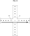
FIG. 5B , still another example of additional guidance is an intersection arbitration flag.FIG. 14 is a diagram for explaining the intersection arbitration flag, in which a black circle indicates a waypoint to which " intersection arbitration flag: OFF" (0 inFIG. 5B ) is assigned, and a white circle indicates a waypoint to which " intersection arbitration flag: ON" (1 inFIG. 5B ) is assigned. "Intersection arbitration flag: ON" is given to the waypoint before the intersection. When thevehicle 10 reaches the waypoint W1 at which the intersection arbitration flag is ON, the control device 11 (travelingcontrol unit 12B, seeFIG. 17 ) of thevehicle 10 transmits an inquiry to themanagement device 70 as to whether an approach to the intersection is allowed. Thevehicle 10 enters the intersection or waits before the intersection based on the answer frommanagement device 70. - The
computing device 71 of themanagement device 70 functionally includes an arbitration unit 71C (seeFIG. 4 ). The position of thevehicle 10 recorded in the vehicle monitoring table 72A (seeFIG. 4 ) is updated every predetermined time (e.g., one or several seconds). When themanagement device 70 receives an inquiry from thevehicle 10 as to whether thevehicle 10 is allowed to enter the intersection, the arbitration unit 71C refers to the vehicle monitoring table to determine whether there is anothervehicle 10 that has entered the intersection related to the inquiry. That is, the arbitration unit 71C determines whether there is anothervehicle 10 having the position information within a predetermined range Ar (seeFIG. 14 ) defined at the intersection related to the inquiry. If noother vehicle 10 has entered the intersection, the arbitration unit 71C sends a response to thevehicle 10 to permit an entry to the intersection. In contrast, if there is anothervehicle 10 entering the intersection, the arbitration unit 71C sends a response to instruct thevehicle 10 to wait before the intersection. Subsequently, the arbitration unit 71C refers to the vehicle monitoring table every predetermined time (e.g., one or several seconds), and determines if there is noother vehicle 10 entering the intersection related to the inquiry. When there is noother vehicle 10 in the intersection, the arbitration unit 71C transmits a response to thevehicle 10 to permit an entry to the intersection. The examples of the additional guidance have been described above. - The processing executed by the
management device 70 and thevehicle 10 as to the traveling at the intersection is not limited to the examples described above. Thevehicle 10 may receive a dummy passage allowance from themanagement device 70 at the entrance of the intersection and return the dummy passage allowance to themanagement device 70 at the exit of the intersection. Specifically, when thevehicle 10 reaches the waypoint W1 at which the intersection arbitration flag is ON, thecontrol device 11 requests themanagement device 70 to send a dummy passage allowance. The issuance of the passage allowance is recorded in thestorage device 72, and the arbitration unit 71C of themanagement device 70 refers to thestorage device 72 to determine whether there is a vehicle to which the passage allowance is issued. If there is no vehicle to which the passage allowance is issued, a dummy passage allowance is issued to thevehicle 10 requesting the passage allowance. That is, the arbitration unit 71C notifies thevehicle 10 that passage is allowed, and records in thestorage device 72 that the passage allowance is issued to thevehicle 10. When reaching the waypoint indicating the exit of the intersection, thevehicle 10 returns the dummy passage allowance to themanagement device 70. That is, thevehicle 10 notifies themanagement device 70 that thevehicle 10 has exited the intersection. The arbitration unit 71C records in thestorage device 72 that the dummy passage allowance has been returned. The example of the additional guidance has been described above. - As described above, the planned
route generating unit 71E refers to the route basic information (FIG. 5B ) and searches for a route from the traveling start position to the traveling end position by using known route search algorithms. In an example, the plannedroute generating unit 71E executes known route search algorithms using all the waypoints representing the drivable routes as nodes. - Alternatively, the route search may not use a waypoint included in the route basic information. For example, the
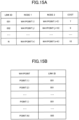
storage device 72 may store first basic information indicating a predetermined drivable route in the vehicle operation area B. The first basic information is configured to reduce computational load for the route search. For example, the first basic information includes fewer nodes than the waypoints included in the route basic information shown inFIGs. 5A and5B . When such first basic information is used, thestorage device 72 may previously store information associating a route obtained from the first basic information with a waypoint. In the following, information associating a route obtained from the first basic information with a series of waypoints is referred to as second basic information. The plannedroute generating unit 71E may perform route search using the first basic information and refer to the second basic information, thereby acquiring waypoints corresponding to the obtained route and using the waypoints as planned route information. In this case, the first basic information and the second basic information constitute route basic information. -
FIG. 15A is a diagram for explaining an example of the first basic information.FIG. 15B is a diagram for explaining an example of the second basic information. The first basic information shown inFIG. 15A defines a plurality of links and nodes that are both ends of the links. The nodes may correspond to intersections on the drivable routes in the vehicle operation area B, and to waypoints of branching and merging points. A link is associated with its length (distance between nodes) and time required to pass the link as a cost. In the second basic information shown inFIG. 15B , links are respectively associated with the waypoints. In the second basic information, all of the waypoints in the drivable route may be respectively associated with the links. The plannedroute generating unit 71E performs route search using the first basic information and specifies a route (nodes and links) from the traveling start position to the traveling end position acquired in S301 (seeFIG. 8 ). Subsequently, the plannedroute generating unit 71E acquires waypoints corresponding to the acquired route (nodes and links) by referring to the second basic information, and uses the acquired waypoints as the planned route information. As shown inFIG. 6 , this method also enables to extract some of the entire waypoints (route basic information) representing the drivable route as the planned route information. The number of nodes defined by the first basic information is smaller than the number of all of the waypoints representing the drivable route in the vehicle operation area B. This serves to reduce the computational load of route search. - The first basic information may not include nodes corresponding to an intersection, a branch point, and a junction. For example, the first basic information may define lanes. Specifically, the relationship between the lanes and the cost for passing through the lanes may be defined in the first basis information. The relationships between lanes include continuation, intersection, adjacent, and branching, for example. The continuation indicates the relationship between the lanes that can be moved in normal driving without changing lanes, for example. The intersection indicates the relationship between lanes having potential collisions. The adjacent indicates the relationship between lanes that are neither connected nor intersecting but adjacent to each other. The branching indicates being too small to be treated as an intersection, such as an entrance from a road to a parking lot. In the second basic information, lanes may be respectively associated with all the waypoints on the drivable route. The planned
route generating unit 71E performs a route search using the first basic information and specifies a route (lane) from the traveling start position to the traveling end position that are acquired in S301. Subsequently, the plannedroute generating unit 71E acquires the waypoints corresponding to the acquired route (lane) by referring to the second basic information, and uses the acquired waypoints as the planned route information. As shown in FIGs. 7A and 7B, this manner also enables to extract some of the entire waypoints representing the drivable routes in the vehicle operation area B as the planned route information. The number of lanes defined by the first basic information is smaller than the number of the entire waypoints representing the drivable route in the vehicle operation area B, whereby the computational load of route search can be reduced. - The planned
route generating unit 71E may divide a planned route that continues from the traveling start position to the traveling end position into a plurality of routes (e.g., first partial route and second partial route). That is, the plannedroute generating unit 71E may divide the waypoints indicating the planned route continuing from the traveling start position to the traveling end position into the waypoints corresponding to the first partial route and the waypoints corresponding to the second partial route, and transmit such waypoints to thevehicle 10. -
FIG. 16 is a diagram for explaining such processing of the plannedroute generating unit 71E. In the example inFIG. 16 , the planned route has a first partial route R1 and a second partial route R2 that intersect at an intersection Cs. Such an intersection of the two partial routes R1 and R2 can be generated when a right turn at the intersection Cs is prohibited, for example. As will be described later, thevehicle 10 moves toward the waypoint closest to its current location among the waypoints in the received planned route information. As such, when thevehicle 10 reaches the intersection Cs, that is, when thevehicle 10 reaches the waypoint W1 inFIG. 16 , the waypoints W2, W3, and W4 are located in similar proximity from the waypoint W1, and this may cause thevehicle 10 to make a wrong direction of travel. In order to avoid such a situation, when the first partial route R1 and the second partial route R2 intersect, as shown inFIGs. 16B and 16C, the plannedroute generating unit 71E divides the waypoints indicating the planned route into waypoints corresponding to the first partial route and waypoints corresponding to the second partial route. - The planned
route generating unit 71E may transmit the waypoints corresponding to the first partial route R1 and the waypoints corresponding to the second partial route R2 to thevehicle 10 at different timings. For example, the plannedroute generating unit 71E may first transmit only the waypoints of the first partial route R1 to thevehicle 10, and transmit the second partial route R2 to thevehicle 10 when thevehicle 10 reaches the waypoint at the end of the first partial route R1. Alternatively, the plannedroute generating unit 71E may transmit the waypoints of the first partial route R1 and the waypoints of the second partial route R2 at substantially the same time. In this case, for the purpose of enabling thecontrol device 11 of thevehicle 10 to determine which of the first partial route information and the second partial route information is to be referred to first, the plannedroute generating unit 71E may attach information indicating the order to the first portion route information and the second partial route information to be sent to thevehicle 10. - For example, the planned
route generating unit 71E may determine whether the planned route includes two partial routes R1 and R2 intersecting each other as follows: When the first basic information described above is used for the route search and two links (or lanes) intersect each other, the intersection may be indicated in the first basic information. If two intersecting links (or lanes) are selected as a result of the route search, the planned route may be divided into the two partial routes such that one of the links is included in the first partial route and the other is included in the second partial route. - In another example, additional information indicating the intersection Cs (e.g., an ID of the intersection) may be added to the waypoints included in the intersection Cs. The planned
route generating unit 71E may determine whether the planned route includes two partial routes R1 and R2 intersecting each other based on such additional information. For example, when the number of waypoints including the ID of the same intersection among the waypoints included in the planning route exceeds a threshold value, it may be determined that the planning route includes two partial routes intersecting each other at the intersection Cs. -
FIG. 17 is a block diagram showing functions of thecomputing device 12 of theautonomous vehicle 10. Thecomputing device 12 functionally includes a currentlocation estimating unit 12A, a travelingcontrol unit 12B, and ananomaly detection unit 12C. - The current
location estimating unit 12A estimates a current location of thevehicle 10. As described above, thevehicle 10 has theexternal sensor group 30 for outputting surrounding information indicating positions of objects in the surrounding of thevehicle 10. Theexternal sensor group 30 includes theLiDAR 31 and thecameras storage device 13 stores map information indicating the positions of objects in the vehicle operation area B. The currentlocation estimating unit 12A matches the surrounding information obtained through theexternal sensor group 30 with the map information recorded in thestorage device 13, thereby estimating the current location of thevehicle 10. For example, the map information is a three-dimensional point cloud map. The surrounding information is, for example, point cloud data acquired through theLiDAR 31. The currentlocation estimating unit 12A outputs the coordinates of the position where the point group data in the point cloud map is matched, that is, the coordinate values (X, Y, Z) in the coordinate system defined in the vehicle operation area B, as the position of the vehicle. - The map information stored in the storage device 13 (specifically, three-dimensional point cloud map) is about the entire vehicle operation area B. As such, when the
vehicle 10 starts traveling toward the desired pick-up location and toward the desired drop-off location, themanagement device 70 does not need to send the map information to thevehicle 10. The map information generally has a large amount of data. In theautonomous driving system 1, the map information is not required to be sent to thevehicle 10 at the start of traveling of thevehicle 10, and thus, troubles related to the reception of the map information does not occur and thevehicle 10 can smoothly start the traveling toward the desired pick-up location or desired drop-off location. - The traveling
control unit 12B refers to the planned route information, which is received from themanagement device 70 and stored in thestorage device 13, to control thedriving mechanism 21, thebraking mechanism 22, and thesteering mechanism 23. The travelingcontrol unit 12B controls thedriving mechanism 21, thebraking mechanism 22, and thesteering mechanism 23 so that thevehicle 10 travels toward the waypoint closest to the current location of thevehicle 10. When the vehicle speed is associated with a waypoint included in the route basic information (seeFIG. 5B ), the drivingcontrol unit 12B may control thedriving mechanism 21 so that thevehicle 10 travels within the range of the vehicle speed. - When the
vehicle 10 arrives at the waypoint to which the additional guidance described with reference to FIGs. 6A and10 to 14 is associated, the travelingcontrol unit 12B may control thedriving mechanism 21, thebraking mechanism 22, thesteering mechanism 23, and theflashers -
FIG. 18 is a diagram for explaining an example of processing executed by thecontrol device 11 during the traveling. Thecontrol device 11 first receives the planned route information from the management device 70 (S401). The planned route information is stored in thestorage device 13. Subsequently, the control device 11 (travelingcontrol unit 12B) acquires a waypoint closest to the current location of thevehicle 10 calculated by the processing of the currentlocation estimating unit 12A from the waypoints included in the planned route information (S402). The travelingcontrol unit 12B controls thedriving mechanism 21, thebraking mechanism 22, and thesteering mechanism 23 based on the current location of thevehicle 10 and the waypoint acquired in S402 (S403). That is, the travelingcontrol unit 12B controls thedriving mechanism 21 and other mechanisms so that thevehicle 10 is directed to the waypoint acquired in S402. - The traveling
control unit 12B acquires additional guidance (e.g., intersection arbitration flag described above) associated with the waypoint acquired in S402 (S404) . The travelingcontrol unit 12B executes the operation according to the additional guidance (S405). The operation according to the additional guidance is, for example, arbitration at the intersection as described above, temporary stop, and flashing of theflashers control unit 12B then determines whether thevehicle 10 has reached the traveling end position specified by the planned route information (S406). If thevehicle 10 has not reached the traveling end position specified by the waypoint, the processing of thecontrol device 11 returns to S402. If thevehicle 10 has reached the traveling end position specified by the waypoint, thecontrol device 11 ends the processing for traveling. When thevehicle 10 arrives at the traveling end position, thecontrol device 11 transmits such information to themanagement device 70. - The
anomaly detection unit 12C monitors a control signal calculated by the travelingcontrol unit 12B for controlling thevehicle 10. When the control signal exhibits an abnormality, such as steep change in the control signal, theanomaly detection unit 12C determines that the abnormality has occurred. In this case, thecomputing device 12 smooths the control signal calculated by the travelingcontrol unit 12B or stops the output of the control signal. - The
storage device 72 stores a masterpoint cloud map 72C (seeFIG. 4 ). In the vehicle operation area B, a new object (e.g., building) may be provided. As such, the point cloud map stored in thestorage device 13 of thevehicle 10 is preferably updated. The vehicle monitoring table 72A stored in thestorage device 72 of thevehicle management device 70 may store a point cloud map stored in astorage device 13 of eachvehicle 10. The information on the point cloud map may include, for example, the latest update time and the version name of the point cloud map stored in thestorage device 13. In the processing of thevehicle monitoring unit 71D, such information may be received from thevehicle 10 at regular time intervals and recorded in the vehicle monitoring table. - As shown in
FIG. 4 , thecomputing device 71 of thevehicle management device 70 functionally includes a point cloudmap management unit 71F. The point cloudmap management unit 71F refers to information on the masterpoint cloud map 72C (e.g., latest update time and/or version name) stored in thestorage device 72 and information on the point cloud map of the respective vehicles 10 (e.g., latest update time and/or version name) recorded in the vehicle monitoring table 72A. When the point cloud map of thevehicle 10 does not match the master point cloud map, the point cloudmap management unit 71F may transmit the master point cloud map (point cloud map) to thevehicle 10. At this time, thevehicle 10 may update the point cloud map stored in thestorage device 13 with the newly received point cloud map. - The latest point cloud map may be transmitted to the
vehicle 10 at a time or a location different from the time or the location at which the planned route information is transmitted to thevehicle 10. For example, the point cloud map may be transmitted to thevehicle 10 at a predetermined location and/or a predetermined time. As described above, upon receiving the forwarding command (planned route information from the current location to the forwarding location) from theforwarding managing unit 71B, thevehicle 10 returns to the forwarding location in the vehicle operation area B (e.g., garage or charging station). The point cloud map may be transmitted to thevehicle 10 when thevehicle 10 is in such a forwarding location. The forwarding command from theforwarding managing unit 71B (i.e., the return of thevehicle 10 to the forwarding location) may be made at a predetermined time. In this manner, the point cloud map is transmitted to thevehicle 10 at a predetermined time. - The point cloud map typically has a large amount of data. As such, the point cloud map may be transmitted to the
vehicle 10 using communication means different from the communication means used when the planned route information is transmitted to thevehicle 10. The planned route information is transmitted to thevehicle 10 via the Internet and a mobile telephone network including a base station, for example. On the other hand, the point cloud map may be transmitted to thevehicle 10 via a wireless LAN or a wired LAN, for example, without going through the Internet and the mobile telephone network. - The transmission of the point cloud map to the
vehicle 10 is not limited to the example described above. For example, similarly to the transmission of the planned route information, the point cloud map may be transmitted to thevehicle 10 via the Internet and the mobile telephone network. -
FIG. 19 is a flow chart showing an example of procedures for generating route basic information stored in thestorage device 72 of thevehicle management device 70. - First, a three-dimensional point cloud map is generated. For generating the point cloud map, the vehicle acquires the point cloud data using the LiDAR while travelling in the vehicle operation area B (S501). This vehicle may be a vehicle other than the
autonomous vehicle 10. While traveling, the vehicle acquires the point cloud data using the LiDAR and also acquires the position information through a GNSS receiver. The vehicle may have an inertial measurement unit (IMU) including an acceleration sensor and an angular velocity sensor. In this case, the position information may be acquired using the output of the IMU while the point cloud data is acquired by the LiDAR. The three-dimensional processing is executed on the point cloud data and the position information acquired in S501A, whereby three-dimensional point cloud map is generated for the entire vehicle operation area B (S502). The coordinate system (X, Y, Z) in the vehicle operation area B may be used as the coordinate system of the point cloud map. The point cloud map generated in this manner may be used as the master point cloud map described above. - Next, while acquiring the point group data using the LiDAR, the vehicle travels along the drivable route in the vehicle operation area B. The point group data acquired by the LiDAR is matched with the three-dimensional point group map generated in S502, and whereby the position information of the route on which the vehicle has traveled (i.e., the drivable route in the vehicle operation area B) is acquired (S503). This position information is coordinate values (X, Y, Z) of the waypoints represented by the coordinate system in the vehicle operation area B and included in the route basic information described referring to FIG. 6B. Subsequently, the coordinate values of the world geodetic system (latitude, longitude, altitude) are set for the waypoints indicating the route on which the vehicle has traveled (S504). The coordinate values of each waypoint in the world geodetic system can be calculated from the latitude and longitude of the origin of the coordinate system in the vehicle operation area B and the rotation angle of the coordinate system in the vehicle operation area B (the rotation angle is the inclination of the coordinate system in the vehicle operation area B in the world geodetic system).
- Next, additional guidance is provided to each waypoint (S505). For example, in S503, when the vehicle travels so as to acquire the position information of the drivable route, a log of the driving operation of the vehicle may be recorded in association with the position information of the drivable route. The log includes information on the operations of the
flashers -
- (1) As described above, a
vehicle management device 70 includes astorage device 72 in which route basic information is stored in advance, where the route basic information includes waypoints arranged along a drivable route (FIG. 5A , L1, L2) previously defined in a vehicle operation area B, and acomputing device 71 for generating planned route information indicating a route to be traveled by avehicle 10 in response to a movement request to the vehicle. Thecomputing device 71 extracts some of the waypoints (FIG. 6 ) included in the route basic information as the planned route information, where the some of the waypoints are arranged from a traveling start position to a traveling end position according to the movement request. Thismanagement device 70 enables to relatively easily generate the planned route. - (2) The
vehicle management device 70 may further include acommunication device 73 for transmitting the planned route information to thevehicle 10. This eliminates the need to perform route search in thevehicle 10, thereby reducing the computational load on thevehicle 10. - (3) The route basic information includes additional guidance in association with the waypoints included in the route basic information, where the additional guidance indicates a predetermined operation to be performed by the vehicle or a predetermined operation that the vehicle is allowed to perform. In this manner, the additional guidance included in the planned route can help control of the
autonomous vehicle 10. - (4) The additional guidance may be information for guiding the vehicle to at least one of operations including a temporary stop of the vehicle, overtaking a vehicle travelling ahead, processing related to an arbitration with another vehicle at an intersection, and flashing of a flasher. In this manner, the additional guidance included in the planned route can help a temporary stop of the vehicle, overtaking a vehicle travelling ahead, processing related to an arbitration with another vehicle at an intersection, or flashing of a flasher.
- (5) Each of the waypoints included in the route basic information may be associated with a coordinate value (X, Y, Z) in a coordinate system defined in the predetermined area and a coordinate value of a world geodetic system. This can specify the pick-up location and the drop-off location desired by the user by the coordinate values of the world geodetic system.
- (6) The route basic information may include first basic information (
FIG. 15A ) and second basic information (FIG. 15B ), where the first basic information defines a plurality of links indicating the drivable route and a plurality of nodes, which are ends of the plurality of links, and the second basic information associates the plurality of links with the waypoints arranged along the drivable route. Thecomputing device 71 may search for a link from the traveling start position to the traveling end position using the first basic information and refer to the second basic information so as to acquire a waypoint corresponding to the link obtained by the search as the planned route information. This serves to reduce the computational load required for the route search. - (7) The route basic information may include first basic information and second basic information, where the first basic information indicates the drivable route previously defined in the predetermined area, and the second basic information associates a route specified by the first basic information with a waypoint. The
computing device 71 may search for a route from the traveling start position to the traveling end position by using the first basic information and refer to the second basic information so as to acquire a waypoint corresponding to the route obtained by the search as the planned route information. By simplifying the first basic information, the computational load required for the route search can be reduced. - (8) The drivable route (
FIG. 5A ) defined in the vehicle operation area B has an annular shape. In this manner, the vehicle can reach the traveling end position by being moved in the traveling direction regardless of the positional relationship between the traveling start position and the traveling end position. - (9) The planned route may continue from the traveling start position according to the movement request to the traveling end position according to the movement request. The planned route may include a first partial route R1 (
FIG. 16 ) and a second partial route R2 (FIG. 16 ) between the traveling start position and the traveling end position. Thecomputing device 71 may divide the waypoints extracted as the planned route into the waypoints corresponding to the first partial route R1 and the waypoints corresponding to the second partial route R2. - (10) The planned route includes an intersection Cs (
FIG. 16 ), the first partial route R1 includes one of two routes intersecting with each other at the intersection Cs, and the second partial route R2 includes the other of the two routes intersecting with each other at the intersection Cs. This helps theautonomous vehicle 10 to properly drive through the intersection. - (11) The
autonomous driving system 1 includes thevehicle management device 70 and thevehicle 10. Thevehicle 10 includes adriving mechanism 21, asteering mechanism 23, and acontrol device 11 that controls thedriving mechanism 21 and thesteering mechanism 23 so that thevehicle 10 travels along a planned route. Thevehicle management device 70 may include acommunication device 73 that transmits the planned route information to thevehicle 10. This eliminates the need to perform route search in thevehicle 10, thereby reducing the computational load on thevehicle 10. - (12) It may be determined whether the
vehicle 10 is on the drivable route. Thevehicle management device 70 does not transmit the planned route information to thevehicle 10 in a case where thevehicle 10 is not on the drivable route. - (13) The movement request to the
vehicle 10 is a request for a movement from a current location of thevehicle 10 to a pick-up location desired by a user, a movement from the pick-up location desired by the user to a drop-off location desired by the user, and a movement from the current location of the vehicle to a forwarding location. - (14) The
vehicle 10 includes anexternal sensor group 30 and a storage device, where theexternal sensor group 30 outputs surrounding information indicating a position of an object around the vehicle, and thestorage device 13 stores map information indicating a position of an object in the vehicle operation area B. Thecontrol device 11 of thevehicle 10 includes a currentlocation estimating unit 12A that matches the surrounding information with the map information so as to estimate a location of thevehicle 10. The map information is transmitted to thevehicle 10 at a timing different from the planned route information. This allows map information having a large amount of data to be safely transmitted to thevehicle 10. - (15) The
vehicle 10 includes anexternal sensor group 30 and astorage device 13, where theexternal sensor group 30 outputs surrounding information indicating a position of an object around thevehicle 10, and thestorage device 13 stores map information indicating a position of an object in the vehicle operation area B. Thecontrol device 11 of thevehicle 10 may include a currentlocation estimating unit 12A that matches the surrounding information with the map information so as to estimate a location of the vehicle. The map information is transmitted to the vehicle using communication means different from communication means for receiving the planned route. This allows map information having a large amount of data to be safely transmitted to the vehicle. - (16) A travel route generating method proposed in this disclosure is a method for generating a planned route indicating a route to be traveled by a vehicle in a predetermined area B. The method includes the steps of acquiring a traveling start position and a traveling end position according to a movement request to the
vehicle 10 and referring to route basic information that includes waypoints arranged along a predetermined drivable route (FIG. 5A ) in the predetermined area B and is stored in astorage device 72 so as to extract some of the waypoints (FIG. 6 ) that are included in the route basic information as the planned route information, where the some of the waypoints are arranged from the traveling start position to the traveling end position. This method enables to relatively easily generate the planned route. - The travel route generating device proposed in the present disclosure is not limited to the
vehicle management device 70 described above. The autonomous driving system proposed in the present disclosure is not limited to theautonomous driving system 1 described above. For example, the route basic information may not include additional guidance such as a temporary stop flag and a turn flag.
Claims (16)
- A travel route generating device, comprising:a storage device in which route basic information is stored in advance, the route basic information including waypoints arranged along a drivable route previously defined in a predetermined area; anda computing device for generating planned route information indicating a route to be traveled by a vehicle in response to a movement request to the vehicle, whereinthe computing device extracts some of the waypoints included in the route basic information as the planned route information, the some of the waypoints being arranged from a traveling start position to a traveling end position according to the movement request.
- The travel route generating device according to claim 1, further comprising a communication device for transmitting the planned route information to the vehicle.
- The travel route generating device according to claim 1, wherein
the route basic information includes additional guidance in association with at least one of the waypoints included in the route basic information, the additional guidance indicating a predetermined operation to be performed by the vehicle or a predetermined operation that the vehicle is allowed to perform. - The travel route generating device according to claim 3, wherein
the additional guidance is information for guiding the vehicle to at least one of operations including a temporary stop of the vehicle, overtaking a vehicle travelling ahead, processing related to an arbitration with another vehicle at an intersection, and flashing of a flasher. - The travel route generating device according to claim 1, wherein
in the route basic information, each of the waypoints is associated with a coordinate value in a coordinate system defined in the predetermined area and a coordinate value of a world geodetic system. - The travel route generating device according to claim 1, whereinthe route basic information includes first basic information and second basic information, the first basic information defining a plurality of links indicating the drivable route and a plurality of nodes, which are ends of the plurality of links, the second basic information associating the plurality of links with the waypoints arranged along the drivable route, andthe computing device searches for a link from the traveling start position to the traveling end position using the first basic information and refers to the second basic information so as to acquire a waypoint corresponding to the link obtained by the search as the planned route information.
- The travel route generating device according to claim 1, whereinthe route basic information includes first basic information and second basic information, the first basic information indicating the drivable route previously defined in the predetermined area, the second basic information associating a route specified by the first basic information with a waypoint, andthe computing device searches for a route from the traveling start position to the traveling end position by using the first basic information and refers to the second basic information so as to acquire a waypoint corresponding to the route obtained by the search as the planned route information.
- The travel route generating device according to claim 1, wherein
the drivable route has an annular shape. - The travel route generating device according to claim 1, whereinthe route defined by the planned route information continues from the traveling start position according to the movement request to the traveling end position according to the movement request,the route defined by the planned route information includes a first partial route and a second partial route between the traveling start position and the traveling end position, andthe computing device divides the waypoints extracted as the route defined by the planned route information into the waypoints corresponding to the first partial route and the waypoints corresponding to the second partial route.
- The travel route generating device according to claim 9, whereinthe route defined by the planned route information includes an intersection,the first partial route includes one of two routes intersecting with each other at the intersection, andthe second partial route includes the other of the two routes intersecting with each other at the intersection.
- An autonomous driving system comprising:the travel route generating device according to claim 1; andthe vehicle, whereinthe vehicle includes a driving mechanism, a steering mechanism, and a control device that controls the driving mechanism and the steering mechanism so that the vehicle travels along the route defined by the planned route information, andthe travel route generating device include a communication device that transmits the planned route information to the vehicle.
- The autonomous driving system according to claim 11, whereinit is determined whether the vehicle is on the drivable route, andthe travel route generating device does not transmit the planned route information to the vehicle in a case where the vehicle is not on the drivable route.
- The autonomous driving system according to claim 11, wherein
the movement request to the vehicle is a request for at least one of a movement from a current location of the vehicle to a pick-up location desired by a user, a movement from the pick-up location desired by the user to a drop-off location desired by the user, or a movement from the current location of the vehicle to a forwarding location. - The autonomous driving system according to claim 11, whereinthe vehicle includes an external sensor and a storage device, the external sensor outputting surrounding information indicating a position of an object around the vehicle, the storage device storing map information indicating a position of an object in the predetermined area,the control device of the vehicle includes a location estimating unit that matches the surrounding information with the map information so as to estimate a location of the vehicle, andthe map information is transmitted to the vehicle at a timing different from the planned route information.
- The autonomous driving system according to claim 11, whereinthe vehicle includes an external sensor and a storage device, the external sensor outputting surrounding information indicating a position of an object around the vehicle, the storage device storing map information indicating a position of an object in the predetermined area,the control device of the vehicle includes a location estimating unit that matches the surrounding information with the map information so as to estimate a location of the vehicle, andthe map information is transmitted to the vehicle using communication means different from communication means for receiving the planned route information.
- A travel route generating method for generating a planned route indicating a route to be traveled by a vehicle in a predetermined area, the method comprising the steps of:acquiring a traveling start position and a traveling end position according to a movement request to the vehicle;referring to route basic information that includes waypoints arranged along a predetermined drivable route in the predetermined area and is stored in a storage device so as to extract some of the waypoints that are included in the route basic information as the planned route information, the some of the waypoints being arranged from the traveling start position to the traveling end position.
Applications Claiming Priority (2)
| Application Number | Priority Date | Filing Date | Title |
|---|---|---|---|
| JP2020086325 | 2020-05-15 | ||
| PCT/JP2021/005702 WO2021229881A1 (en) | 2020-05-15 | 2021-02-16 | Travel route generation device, travel route generation method, and automatic driving system |
Publications (2)
| Publication Number | Publication Date |
|---|---|
| EP4151952A1 true EP4151952A1 (en) | 2023-03-22 |
| EP4151952A4 EP4151952A4 (en) | 2023-11-08 |
Family
ID=78524620
Family Applications (1)
| Application Number | Title | Priority Date | Filing Date |
|---|---|---|---|
| EP21804109.3A Withdrawn EP4151952A4 (en) | 2020-05-15 | 2021-02-16 | TRAVEL ROUTE GENERATION DEVICE, TRAVEL ROUTE GENERATION METHOD, AND AUTOMATIC DRIVING SYSTEM |
Country Status (3)
| Country | Link |
|---|---|
| EP (1) | EP4151952A4 (en) |
| JP (1) | JP7408793B2 (en) |
| WO (1) | WO2021229881A1 (en) |
Cited By (1)
| Publication number | Priority date | Publication date | Assignee | Title |
|---|---|---|---|---|
| US20260009648A1 (en) * | 2022-10-11 | 2026-01-08 | WHILL, Inc. | Information processing method, program, information processing apparatus, information processing system, and map data generation method |
Families Citing this family (2)
| Publication number | Priority date | Publication date | Assignee | Title |
|---|---|---|---|---|
| CN117877303A (en) * | 2024-01-03 | 2024-04-12 | 亿海蓝(北京)数据技术股份公司 | Vehicle route planning and indication method, system, storage medium and electronic device |
| JP7727051B1 (en) | 2024-05-28 | 2025-08-20 | 株式会社シンテックホズミ | Travel management system and transport robot system |
Family Cites Families (10)
| Publication number | Priority date | Publication date | Assignee | Title |
|---|---|---|---|---|
| JP2004110287A (en) * | 2002-09-17 | 2004-04-08 | Mitsubishi Heavy Ind Ltd | AGV route search method and program |
| JP4091444B2 (en) * | 2003-01-15 | 2008-05-28 | 株式会社ザナヴィ・インフォマティクス | Navigation device |
| AU2009251839C1 (en) * | 2008-04-01 | 2015-09-17 | Uber Technologies, Inc. | Transmission of routes between client and server using route IDs |
| US8831876B2 (en) * | 2009-12-28 | 2014-09-09 | Clarion Co., Ltd. | Navigation device, route guidance method, and program |
| JP6464500B2 (en) * | 2016-03-11 | 2019-02-06 | パナソニックIpマネジメント株式会社 | Automatic vehicle allocation system and server device |
| AU2018307660B2 (en) * | 2017-07-28 | 2022-07-14 | Crown Equipment Corporation | Traffic management for materials handling vehicles in a warehouse environment |
| JP7026135B2 (en) | 2017-12-22 | 2022-02-25 | ヤマハ発動機株式会社 | On-demand default route self-driving vehicle |
| JP7035531B2 (en) * | 2017-12-28 | 2022-03-15 | トヨタ自動車株式会社 | Vehicle operation management system |
| US11441913B2 (en) * | 2018-08-20 | 2022-09-13 | Uatc, Llc | Autonomous vehicle waypoint routing |
| CN109976332A (en) * | 2018-12-29 | 2019-07-05 | 惠州市德赛西威汽车电子股份有限公司 | One kind being used for unpiloted accurately graph model and autonomous navigation system |
-
2021
- 2021-02-16 EP EP21804109.3A patent/EP4151952A4/en not_active Withdrawn
- 2021-02-16 JP JP2022522523A patent/JP7408793B2/en active Active
- 2021-02-16 WO PCT/JP2021/005702 patent/WO2021229881A1/en not_active Ceased
Cited By (1)
| Publication number | Priority date | Publication date | Assignee | Title |
|---|---|---|---|---|
| US20260009648A1 (en) * | 2022-10-11 | 2026-01-08 | WHILL, Inc. | Information processing method, program, information processing apparatus, information processing system, and map data generation method |
Also Published As
| Publication number | Publication date |
|---|---|
| WO2021229881A1 (en) | 2021-11-18 |
| EP4151952A4 (en) | 2023-11-08 |
| JPWO2021229881A1 (en) | 2021-11-18 |
| JP7408793B2 (en) | 2024-01-05 |
Similar Documents
| Publication | Publication Date | Title |
|---|---|---|
| CN111833645B (en) | Parking lot management device, parking lot management method, and storage medium | |
| JP6561357B2 (en) | Vehicle control system, vehicle control method, and vehicle control program | |
| CN110099833B (en) | Vehicle control system, vehicle control method, and storage medium | |
| JP6465497B2 (en) | Information display device, information display method, and information display program | |
| CN112208535B (en) | Vehicle control device, vehicle control method and storage medium | |
| US20190250001A1 (en) | Vehicle control system, vehicle control method, and vehicle storage medium | |
| US11345365B2 (en) | Control device, getting-into/out facility, control method, and storage medium | |
| KR20170082165A (en) | System for autonomous driving service of vehicle, cloud server thereof and method thereof | |
| CN110001641B (en) | Vehicle control device, vehicle control method, and storage medium | |
| CN110167810A (en) | Vehicle control system, control method for vehicle and vehicle control program | |
| US20200311623A1 (en) | Parking management apparatus, method for controlling parking management apparatus, and storage medium | |
| JP2019185293A (en) | Vehicle remote control method and vehicle remote control device | |
| US20210086649A1 (en) | Vehicle control system, vehicle control method, and program | |
| EP4151952A1 (en) | Travel route generation device, travel route generation method, and automatic driving system | |
| JP7458908B2 (en) | Vehicle driving support method and vehicle driving support system | |
| EP4057253B1 (en) | System, management method, automated driving vehicle, and program | |
| US20210107509A1 (en) | Vehicle control system, vehicle control device, and vehicle control method | |
| CN110239544A (en) | Controller of vehicle, control method for vehicle and storage medium | |
| CN111665835A (en) | Vehicle control system and vehicle control method | |
| US20210303002A1 (en) | Accommodation area management device | |
| JP2019095210A (en) | Vehicle controller, method for controlling vehicle, and program | |
| US20210302978A1 (en) | Accommodation area management device | |
| JP6460420B2 (en) | Information display device, information display method, and information display program | |
| CN111688677B (en) | Vehicle control system | |
| JP2020106920A (en) | Vehicle control apparatus, vehicle control method, and program |
Legal Events
| Date | Code | Title | Description |
|---|---|---|---|
| STAA | Information on the status of an ep patent application or granted ep patent |
Free format text: STATUS: THE INTERNATIONAL PUBLICATION HAS BEEN MADE |
|
| PUAI | Public reference made under article 153(3) epc to a published international application that has entered the european phase |
Free format text: ORIGINAL CODE: 0009012 |
|
| STAA | Information on the status of an ep patent application or granted ep patent |
Free format text: STATUS: REQUEST FOR EXAMINATION WAS MADE |
|
| 17P | Request for examination filed |
Effective date: 20221109 |
|
| AK | Designated contracting states |
Kind code of ref document: A1 Designated state(s): AL AT BE BG CH CY CZ DE DK EE ES FI FR GB GR HR HU IE IS IT LI LT LU LV MC MK MT NL NO PL PT RO RS SE SI SK SM TR |
|
| DAV | Request for validation of the european patent (deleted) | ||
| DAX | Request for extension of the european patent (deleted) | ||
| P01 | Opt-out of the competence of the unified patent court (upc) registered |
Effective date: 20230713 |
|
| A4 | Supplementary search report drawn up and despatched |
Effective date: 20231010 |
|
| RIC1 | Information provided on ipc code assigned before grant |
Ipc: G08G 1/095 20060101ALI20231004BHEP Ipc: G08G 1/09 20060101ALI20231004BHEP Ipc: G05D 1/02 20200101ALI20231004BHEP Ipc: G01C 21/26 20060101ALI20231004BHEP Ipc: B60W 30/10 20060101ALI20231004BHEP Ipc: G01C 21/34 20060101AFI20231004BHEP |
|
| STAA | Information on the status of an ep patent application or granted ep patent |
Free format text: STATUS: EXAMINATION IS IN PROGRESS |
|
| 17Q | First examination report despatched |
Effective date: 20240806 |
|
| STAA | Information on the status of an ep patent application or granted ep patent |
Free format text: STATUS: THE APPLICATION IS DEEMED TO BE WITHDRAWN |
|
| 18D | Application deemed to be withdrawn |
Effective date: 20250725 |