EP4151939A1 - Trim breaker having metallic insert for decreased gas permeation - Google Patents
Trim breaker having metallic insert for decreased gas permeation Download PDFInfo
- Publication number
- EP4151939A1 EP4151939A1 EP22186361.6A EP22186361A EP4151939A1 EP 4151939 A1 EP4151939 A1 EP 4151939A1 EP 22186361 A EP22186361 A EP 22186361A EP 4151939 A1 EP4151939 A1 EP 4151939A1
- Authority
- EP
- European Patent Office
- Prior art keywords
- trim breaker
- metallic plate
- channel
- wrapper
- vacuum insulated
- Prior art date
- Legal status (The legal status is an assumption and is not a legal conclusion. Google has not performed a legal analysis and makes no representation as to the accuracy of the status listed.)
- Withdrawn
Links
Images



Classifications
-
- B—PERFORMING OPERATIONS; TRANSPORTING
- B32—LAYERED PRODUCTS
- B32B—LAYERED PRODUCTS, i.e. PRODUCTS BUILT-UP OF STRATA OF FLAT OR NON-FLAT, e.g. CELLULAR OR HONEYCOMB, FORM
- B32B15/00—Layered products comprising a layer of metal
- B32B15/04—Layered products comprising a layer of metal comprising metal as the main or only constituent of a layer, which is next to another layer of the same or of a different material
- B32B15/08—Layered products comprising a layer of metal comprising metal as the main or only constituent of a layer, which is next to another layer of the same or of a different material of synthetic resin
- B32B15/082—Layered products comprising a layer of metal comprising metal as the main or only constituent of a layer, which is next to another layer of the same or of a different material of synthetic resin comprising vinyl resins; comprising acrylic resins
-
- B—PERFORMING OPERATIONS; TRANSPORTING
- B29—WORKING OF PLASTICS; WORKING OF SUBSTANCES IN A PLASTIC STATE IN GENERAL
- B29C—SHAPING OR JOINING OF PLASTICS; SHAPING OF MATERIAL IN A PLASTIC STATE, NOT OTHERWISE PROVIDED FOR; AFTER-TREATMENT OF THE SHAPED PRODUCTS, e.g. REPAIRING
- B29C45/00—Injection moulding, i.e. forcing the required volume of moulding material through a nozzle into a closed mould; Apparatus therefor
- B29C45/0013—Injection moulding, i.e. forcing the required volume of moulding material through a nozzle into a closed mould; Apparatus therefor using fillers dispersed in the moulding material, e.g. metal particles
-
- B—PERFORMING OPERATIONS; TRANSPORTING
- B29—WORKING OF PLASTICS; WORKING OF SUBSTANCES IN A PLASTIC STATE IN GENERAL
- B29C—SHAPING OR JOINING OF PLASTICS; SHAPING OF MATERIAL IN A PLASTIC STATE, NOT OTHERWISE PROVIDED FOR; AFTER-TREATMENT OF THE SHAPED PRODUCTS, e.g. REPAIRING
- B29C45/00—Injection moulding, i.e. forcing the required volume of moulding material through a nozzle into a closed mould; Apparatus therefor
- B29C45/14—Injection moulding, i.e. forcing the required volume of moulding material through a nozzle into a closed mould; Apparatus therefor incorporating preformed parts or layers, e.g. injection moulding around inserts or for coating articles
- B29C45/14336—Coating a portion of the article, e.g. the edge of the article
-
- B—PERFORMING OPERATIONS; TRANSPORTING
- B29—WORKING OF PLASTICS; WORKING OF SUBSTANCES IN A PLASTIC STATE IN GENERAL
- B29C—SHAPING OR JOINING OF PLASTICS; SHAPING OF MATERIAL IN A PLASTIC STATE, NOT OTHERWISE PROVIDED FOR; AFTER-TREATMENT OF THE SHAPED PRODUCTS, e.g. REPAIRING
- B29C45/00—Injection moulding, i.e. forcing the required volume of moulding material through a nozzle into a closed mould; Apparatus therefor
- B29C45/14—Injection moulding, i.e. forcing the required volume of moulding material through a nozzle into a closed mould; Apparatus therefor incorporating preformed parts or layers, e.g. injection moulding around inserts or for coating articles
- B29C45/14778—Injection moulding, i.e. forcing the required volume of moulding material through a nozzle into a closed mould; Apparatus therefor incorporating preformed parts or layers, e.g. injection moulding around inserts or for coating articles the article consisting of a material with particular properties, e.g. porous, brittle
-
- B—PERFORMING OPERATIONS; TRANSPORTING
- B32—LAYERED PRODUCTS
- B32B—LAYERED PRODUCTS, i.e. PRODUCTS BUILT-UP OF STRATA OF FLAT OR NON-FLAT, e.g. CELLULAR OR HONEYCOMB, FORM
- B32B15/00—Layered products comprising a layer of metal
- B32B15/04—Layered products comprising a layer of metal comprising metal as the main or only constituent of a layer, which is next to another layer of the same or of a different material
- B32B15/08—Layered products comprising a layer of metal comprising metal as the main or only constituent of a layer, which is next to another layer of the same or of a different material of synthetic resin
- B32B15/09—Layered products comprising a layer of metal comprising metal as the main or only constituent of a layer, which is next to another layer of the same or of a different material of synthetic resin comprising polyesters
-
- B—PERFORMING OPERATIONS; TRANSPORTING
- B32—LAYERED PRODUCTS
- B32B—LAYERED PRODUCTS, i.e. PRODUCTS BUILT-UP OF STRATA OF FLAT OR NON-FLAT, e.g. CELLULAR OR HONEYCOMB, FORM
- B32B15/00—Layered products comprising a layer of metal
- B32B15/18—Layered products comprising a layer of metal comprising iron or steel
-
- D—TEXTILES; PAPER
- D06—TREATMENT OF TEXTILES OR THE LIKE; LAUNDERING; FLEXIBLE MATERIALS NOT OTHERWISE PROVIDED FOR
- D06F—LAUNDERING, DRYING, IRONING, PRESSING OR FOLDING TEXTILE ARTICLES
- D06F39/00—Details of washing machines not specific to a single type of machines covered by groups D06F9/00 - D06F27/00
- D06F39/12—Casings; Tubs
-
- F—MECHANICAL ENGINEERING; LIGHTING; HEATING; WEAPONS; BLASTING
- F24—HEATING; RANGES; VENTILATING
- F24C—DOMESTIC STOVES OR RANGES ; DETAILS OF DOMESTIC STOVES OR RANGES, OF GENERAL APPLICATION
- F24C15/00—Details
- F24C15/02—Doors specially adapted for stoves or ranges
- F24C15/021—Doors specially adapted for stoves or ranges sealings for doors or transparent panel
-
- F—MECHANICAL ENGINEERING; LIGHTING; HEATING; WEAPONS; BLASTING
- F25—REFRIGERATION OR COOLING; COMBINED HEATING AND REFRIGERATION SYSTEMS; HEAT PUMP SYSTEMS; MANUFACTURE OR STORAGE OF ICE; LIQUEFACTION SOLIDIFICATION OF GASES
- F25D—REFRIGERATORS; COLD ROOMS; ICE-BOXES; COOLING OR FREEZING APPARATUS NOT OTHERWISE PROVIDED FOR
- F25D23/00—General constructional features
- F25D23/08—Parts formed wholly or mainly of plastics materials
- F25D23/082—Strips
- F25D23/085—Breaking strips
-
- B—PERFORMING OPERATIONS; TRANSPORTING
- B29—WORKING OF PLASTICS; WORKING OF SUBSTANCES IN A PLASTIC STATE IN GENERAL
- B29K—INDEXING SCHEME ASSOCIATED WITH SUBCLASSES B29B, B29C OR B29D, RELATING TO MOULDING MATERIALS OR TO MATERIALS FOR MOULDS, REINFORCEMENTS, FILLERS OR PREFORMED PARTS, e.g. INSERTS
- B29K2027/00—Use of polyvinylhalogenides or derivatives thereof as moulding material
- B29K2027/06—PVC, i.e. polyvinylchloride
-
- B—PERFORMING OPERATIONS; TRANSPORTING
- B29—WORKING OF PLASTICS; WORKING OF SUBSTANCES IN A PLASTIC STATE IN GENERAL
- B29K—INDEXING SCHEME ASSOCIATED WITH SUBCLASSES B29B, B29C OR B29D, RELATING TO MOULDING MATERIALS OR TO MATERIALS FOR MOULDS, REINFORCEMENTS, FILLERS OR PREFORMED PARTS, e.g. INSERTS
- B29K2067/00—Use of polyesters or derivatives thereof, as moulding material
- B29K2067/003—PET, i.e. poylethylene terephthalate
-
- B—PERFORMING OPERATIONS; TRANSPORTING
- B29—WORKING OF PLASTICS; WORKING OF SUBSTANCES IN A PLASTIC STATE IN GENERAL
- B29K—INDEXING SCHEME ASSOCIATED WITH SUBCLASSES B29B, B29C OR B29D, RELATING TO MOULDING MATERIALS OR TO MATERIALS FOR MOULDS, REINFORCEMENTS, FILLERS OR PREFORMED PARTS, e.g. INSERTS
- B29K2509/00—Use of inorganic materials not provided for in groups B29K2503/00 - B29K2507/00, as filler
- B29K2509/08—Glass
-
- B—PERFORMING OPERATIONS; TRANSPORTING
- B29—WORKING OF PLASTICS; WORKING OF SUBSTANCES IN A PLASTIC STATE IN GENERAL
- B29K—INDEXING SCHEME ASSOCIATED WITH SUBCLASSES B29B, B29C OR B29D, RELATING TO MOULDING MATERIALS OR TO MATERIALS FOR MOULDS, REINFORCEMENTS, FILLERS OR PREFORMED PARTS, e.g. INSERTS
- B29K2509/00—Use of inorganic materials not provided for in groups B29K2503/00 - B29K2507/00, as filler
- B29K2509/10—Mica
-
- B—PERFORMING OPERATIONS; TRANSPORTING
- B29—WORKING OF PLASTICS; WORKING OF SUBSTANCES IN A PLASTIC STATE IN GENERAL
- B29K—INDEXING SCHEME ASSOCIATED WITH SUBCLASSES B29B, B29C OR B29D, RELATING TO MOULDING MATERIALS OR TO MATERIALS FOR MOULDS, REINFORCEMENTS, FILLERS OR PREFORMED PARTS, e.g. INSERTS
- B29K2705/00—Use of metals, their alloys or their compounds, for preformed parts, e.g. for inserts
- B29K2705/08—Transition metals
- B29K2705/12—Iron
-
- B—PERFORMING OPERATIONS; TRANSPORTING
- B29—WORKING OF PLASTICS; WORKING OF SUBSTANCES IN A PLASTIC STATE IN GENERAL
- B29K—INDEXING SCHEME ASSOCIATED WITH SUBCLASSES B29B, B29C OR B29D, RELATING TO MOULDING MATERIALS OR TO MATERIALS FOR MOULDS, REINFORCEMENTS, FILLERS OR PREFORMED PARTS, e.g. INSERTS
- B29K2995/00—Properties of moulding materials, reinforcements, fillers, preformed parts or moulds
- B29K2995/0037—Other properties
- B29K2995/0065—Permeability to gases
- B29K2995/0067—Permeability to gases non-permeable
-
- B—PERFORMING OPERATIONS; TRANSPORTING
- B32—LAYERED PRODUCTS
- B32B—LAYERED PRODUCTS, i.e. PRODUCTS BUILT-UP OF STRATA OF FLAT OR NON-FLAT, e.g. CELLULAR OR HONEYCOMB, FORM
- B32B2264/00—Composition or properties of particles which form a particulate layer or are present as additives
- B32B2264/10—Inorganic particles
- B32B2264/101—Glass
-
- B—PERFORMING OPERATIONS; TRANSPORTING
- B32—LAYERED PRODUCTS
- B32B—LAYERED PRODUCTS, i.e. PRODUCTS BUILT-UP OF STRATA OF FLAT OR NON-FLAT, e.g. CELLULAR OR HONEYCOMB, FORM
- B32B2307/00—Properties of the layers or laminate
- B32B2307/30—Properties of the layers or laminate having particular thermal properties
- B32B2307/304—Insulating
-
- B—PERFORMING OPERATIONS; TRANSPORTING
- B32—LAYERED PRODUCTS
- B32B—LAYERED PRODUCTS, i.e. PRODUCTS BUILT-UP OF STRATA OF FLAT OR NON-FLAT, e.g. CELLULAR OR HONEYCOMB, FORM
- B32B2307/00—Properties of the layers or laminate
- B32B2307/70—Other properties
- B32B2307/724—Permeability to gases, adsorption
- B32B2307/7242—Non-permeable
-
- B—PERFORMING OPERATIONS; TRANSPORTING
- B32—LAYERED PRODUCTS
- B32B—LAYERED PRODUCTS, i.e. PRODUCTS BUILT-UP OF STRATA OF FLAT OR NON-FLAT, e.g. CELLULAR OR HONEYCOMB, FORM
- B32B2509/00—Household appliances
- B32B2509/10—Refrigerators or refrigerating equipment
-
- F—MECHANICAL ENGINEERING; LIGHTING; HEATING; WEAPONS; BLASTING
- F25—REFRIGERATION OR COOLING; COMBINED HEATING AND REFRIGERATION SYSTEMS; HEAT PUMP SYSTEMS; MANUFACTURE OR STORAGE OF ICE; LIQUEFACTION SOLIDIFICATION OF GASES
- F25D—REFRIGERATORS; COLD ROOMS; ICE-BOXES; COOLING OR FREEZING APPARATUS NOT OTHERWISE PROVIDED FOR
- F25D2201/00—Insulation
- F25D2201/10—Insulation with respect to heat
-
- F—MECHANICAL ENGINEERING; LIGHTING; HEATING; WEAPONS; BLASTING
- F25—REFRIGERATION OR COOLING; COMBINED HEATING AND REFRIGERATION SYSTEMS; HEAT PUMP SYSTEMS; MANUFACTURE OR STORAGE OF ICE; LIQUEFACTION SOLIDIFICATION OF GASES
- F25D—REFRIGERATORS; COLD ROOMS; ICE-BOXES; COOLING OR FREEZING APPARATUS NOT OTHERWISE PROVIDED FOR
- F25D2201/00—Insulation
- F25D2201/10—Insulation with respect to heat
- F25D2201/14—Insulation with respect to heat using subatmospheric pressure
-
- F—MECHANICAL ENGINEERING; LIGHTING; HEATING; WEAPONS; BLASTING
- F25—REFRIGERATION OR COOLING; COMBINED HEATING AND REFRIGERATION SYSTEMS; HEAT PUMP SYSTEMS; MANUFACTURE OR STORAGE OF ICE; LIQUEFACTION SOLIDIFICATION OF GASES
- F25D—REFRIGERATORS; COLD ROOMS; ICE-BOXES; COOLING OR FREEZING APPARATUS NOT OTHERWISE PROVIDED FOR
- F25D23/00—General constructional features
- F25D23/06—Walls
- F25D23/062—Walls defining a cabinet
- F25D23/064—Walls defining a cabinet formed by moulding, e.g. moulding in situ
-
- F—MECHANICAL ENGINEERING; LIGHTING; HEATING; WEAPONS; BLASTING
- F25—REFRIGERATION OR COOLING; COMBINED HEATING AND REFRIGERATION SYSTEMS; HEAT PUMP SYSTEMS; MANUFACTURE OR STORAGE OF ICE; LIQUEFACTION SOLIDIFICATION OF GASES
- F25D—REFRIGERATORS; COLD ROOMS; ICE-BOXES; COOLING OR FREEZING APPARATUS NOT OTHERWISE PROVIDED FOR
- F25D23/00—General constructional features
- F25D23/06—Walls
- F25D23/065—Details
- F25D23/066—Liners
-
- Y—GENERAL TAGGING OF NEW TECHNOLOGICAL DEVELOPMENTS; GENERAL TAGGING OF CROSS-SECTIONAL TECHNOLOGIES SPANNING OVER SEVERAL SECTIONS OF THE IPC; TECHNICAL SUBJECTS COVERED BY FORMER USPC CROSS-REFERENCE ART COLLECTIONS [XRACs] AND DIGESTS
- Y02—TECHNOLOGIES OR APPLICATIONS FOR MITIGATION OR ADAPTATION AGAINST CLIMATE CHANGE
- Y02B—CLIMATE CHANGE MITIGATION TECHNOLOGIES RELATED TO BUILDINGS, e.g. HOUSING, HOUSE APPLIANCES OR RELATED END-USER APPLICATIONS
- Y02B40/00—Technologies aiming at improving the efficiency of home appliances, e.g. induction cooking or efficient technologies for refrigerators, freezers or dish washers
Definitions
- the device is in the field of appliance cabinets, and more specifically, a trim breaker for an appliance cabinet that includes a metallic insert for diminishing gas permeation through the trim breaker.
- a vacuum insulated structure includes a trim breaker having a wrapper channel and a liner channel that extend perimetrically about the trim breaker.
- An inner liner is attached to the trim breaker at the liner channel.
- An outer wrapper is attached to the trim breaker at the wrapper channel.
- a metallic plate is disposed within the trim breaker and extends from a first area proximate the liner channel to a second area proximate the wrapper channel. The metallic plate defines an internal barrier to gas permeation through the trim breaker.
- a trim breaker for a vacuum insulated structure includes a plastic body that defines a wrapper channel and a liner channel. A plurality of gas-blocking flakes are disposed throughout the plastic body. A metallic plate is disposed entirely within the trim breaker and extends from a first area proximate the liner channel to a second area proximate the wrapper channel.
- a vacuum insulated structure includes a trim breaker having a wrapper channel and a liner channel.
- An inner liner is attached to the trim breaker at the liner channel.
- An outer wrapper is attached to the trim breaker at the wrapper channel.
- a metallic plate is insert injection molded within the trim breaker and extends from a first area proximate the liner channel to a second area proximate the wrapper channel. The metallic plate defines an internal barrier to gas permeation through the trim breaker.
- the present illustrated embodiments reside primarily in combinations of method steps and apparatus components related to a trim breaker for an appliance cabinet having a metallic plate inserted therein. Accordingly, the apparatus components and method steps have been represented, where appropriate, by conventional symbols in the drawings, showing only those specific details that are pertinent to understanding the embodiments of the present disclosure so as not to obscure the disclosure with details that will be readily apparent to those of ordinary skill in the art having the benefit of the description herein. Further, like numerals in the description and drawings represent like elements.
- the terms “upper,” “lower,” “right,” “left,” “rear,” “front,” “vertical,” “horizontal,” and derivatives thereof shall relate to the disclosure as oriented in FIG. 1 .
- the term “front” shall refer to the surface of the element closer to an intended viewer, and the term “rear” shall refer to the surface of the element further from the intended viewer.
- the disclosure may assume various alternative orientations, except where expressly specified to the contrary.
- the specific devices and processes illustrated in the attached drawings, and described in the following specification are simply exemplary embodiments of the inventive concepts defined in the appended claims. Hence, specific dimensions and other physical characteristics relating to the embodiments disclosed herein are not to be considered as limiting, unless the claims expressly state otherwise.
- reference numeral 10 generally refers to a trim breaker that is incorporated within a structural cabinet 16 for an appliance 40.
- the trim breaker 10 extends between opposing metallic plates 24, typically in the form of an outer wrapper 12 and an inner liner 14, that cooperate to form the structural cabinet 16 having an insulating cavity 18 defined therein.
- the structural cabinet 16 can be in the form of a vacuum insulated structure that includes a trim breaker 10 having a wrapper channel 20 and a liner channel 22 that extend perimetrically about the trim breaker 10.
- the inner liner 14 is attached to the liner channel 22 of the trim breaker 10 and the outer wrapper 12 is attached to the trim breaker 10 at the wrapper channel 20.
- a metallic plate 24 is disposed within the trim breaker 10 and extends from a first area 26 proximate the liner channel 22 to a second area 28 proximate the wrapper channel 20.
- the inner liner 14 and the outer wrapper 12 can be made of a metallic material that is generally resistant to gas permeation therethrough.
- the trim breaker 10 that extends between the inner liner 14 and the outer wrapper 12 can be made of a plastic material 32.
- Plastic is generally a material that, by itself, allows gas to permeate therethrough. In the condition of a vacuum insulated structure, this gas permeation can, over time, allow gas to infiltrate into the insulating cavity 18 and degrade the at least partial vacuum 70 that is defined within the insulating cavity 18 of the structural cabinet 16.
- the inclusion of the metallic plate 24 within the trim breaker 10 reinforces the trim breaker 10 and also provides an additional internal barrier 30 to gas permeation that can limit the amount of gas that can permeate through the trim breaker 10 over time.
- the metallic plate 24 can also slow the rate of gas permeation by a significant amount.
- This configuration can extend the life of the at least partial vacuum 70 within the insulating cavity 18. In turn, this configuration can extend the life of an appliance 40 and the effectiveness and efficiency of the appliance 40 over its lifespan.
- the trim breaker 10 includes a plastic material 32 that can be injection molded around the metallic plate 24.
- the metallic plate 24 can be entirely encased within the plastic material 32 of the trim breaker 10 as a single unitary piece. In such an embodiment, no portion of the metallic plate 24 is visible from the outside surface 50 of the trim breaker 10.
- the inner liner 14 and the outer wrapper 12 are prevented from having any direct physical connection with the metallic plate 24.
- thermal conductivity through the metal components of the structural cabinet 16 is prevented.
- the metallic plate 24 and the metallic material of the inner liner 14 and the outer wrapper 12 provide a substantially continuous barrier to gas permeation around the insulating cavity 18.
- the only gaps are defined by the spaces 52 between the metallic plate 24 and the inner liner 14 and the outer wrapper 12, respectively.
- FIGS. 5-7 which illustrate a process for forming the trim breaker 10
- a portion of the trim breaker 10 may be at least partially exposed within an outside surface 50 of the trim breaker 10.
- an edge 60 of the metallic plate 24 may be co-planar with a plate-supporting portion 62 of the trim breaker 10.
- This plate-supporting portion 62 of the trim breaker 10 may be used to support the metallic plate 24 within a mold 64 so that injectable material 66 that is injected into the mold 64 and molded around the metallic plate 24 can be accurately positioned so that the injectable material 66 surrounds the remaining portions of the metallic plate 24 other than the edge 60 of the metallic plate 24.
- the edge 60 of the metallic plate 24 and the plate-supporting portion 62 of the trim breaker 10 can be positioned within a surface of the trim breaker 10 that faces into the insulating cavity 18 of the structural cabinet 16. Through this configuration, the edge 60 of the metallic plate 24 is positioned adjacent to an insulating material 68 and exposed to the at least partial vacuum 70 maintained within the insulating cavity 18.
- the entire metallic plate 24 can be embedded within the material of the trim breaker 10 so that the metallic plate 24 is completely surrounded by the injectable material 66 and is not exposed to areas outside of the trim breaker 10.
- the metallic plate 24 can be insert injection molded within a mold 64. Through this process, the metallic plate 24 can be positioned within the mold 64 and can be positioned by one or more pins 80, that position the metallic plate 24 within the mold 64 so that the metallic plate 24 is supported in a consistent position as the injectable material 66 flows around the metallic plate 24 to form the structure of the trim breaker 10.
- the voids left behind by the use of the pins 80 may be backfilled so that the entire metallic plate 24 is surrounded by the plastic material 32 of the trim breaker 10.
- the location of the pins 80 may also be oriented so that the voids within the plastic material 32 of the trim breaker 10 left behind by the use of the pins 80 are located within, or exposed to, the insulating cavity 18 for the structural cabinet 16. In either instance, it should be understood that the injectable material 66 of the trim breaker 10 is intended to surround, or substantially surround, the metallic plate 24.
- trim breaker 10 may be exposed, such as the edge 60 of the metallic plate 24 or the location of the supporting pins 80 from the mold 64, which may provide for a minimal exposure of the metallic plate 24 to areas outside of the trim breaker 10.
- the injectable material 66 that surrounds the metallic plate 24 can also include materials that resist, or partially resist, gas permeation.
- various aspects of the device can include gas-blocking flakes 90 that are incorporated within the injectable material 66 of the trim breaker 10.
- These gas-blocking flakes 90 can include mica, glass particles, or other similar naturally-occurring or manufactured particles that can be included within the injectable material 66 to assist in preventing gas permeation through the trim breaker 10.
- the injectable material 66 is a substantially homogenous mixture of the plastic material 32 and the gas-blocking flakes 90.
- the substantial homogeneity of the injectable material 66 is achieved through the size of the gas-blocking flakes 90 being substantially microscopic, such that each particle of the gas-blocking flakes 90 has a dimension in the order of microns.
- the small size of these gas-blocking flakes 90 make them substantially imperceptible with a naked eye when mixed with an injectable material 66. Accordingly, the substantial homogeneity of the injectable material 66 can be achieved when the gas-blocking flakes 90 are incorporated within the plastic material 32 of the injectable material 66.
- the trim breaker 10 that can be used within vacuum insulated structures, such as the structural cabinet 16 described herein, can include a plastic body 100 that defines the wrapper channel 20 and the liner channel 22. A plurality of gas-blocking flakes 90 are disposed throughout the material of the plastic body 100.
- the metallic plate 24 is disposed entirely within the trim breaker 10 and extends from the first area 26 proximate the liner channel 22 to the second area 28 proximate the wrapper channel 20.
- the first and second areas 26, 28 between which the metallic plate 24 extends are areas within an interior of the trim breaker 10.
- the first area 26 proximate the liner channel 22 is within a portion of the trim breaker 10 that defines the liner channel 22.
- This first area 26, as with the metallic plate 24, is positioned entirely within the material of the trim breaker 10. Accordingly, the first edge 102 of the metallic plate 24 is located at this first area 26 proximate the liner channel 22 and is typically entirely encased within the trim breaker 10.
- the first edge 102, or a portion of the first edge 102 of the metallic plate 24, can be co-planar with the plate-supporting portion 62 of the trim breaker 10, such that the first edge 102 of the metallic plate 24, or a portion thereof, is exposed to the exterior of the trim breaker 10, but is located within the insulating cavity 18 for the structural cabinet 16.
- the second edge 104 of the trim breaker 10 is positioned within the second area 28 that is positioned proximate the wrapper channel 20. This second area 28 is configured to be located within an interior portion of the trim breaker 10 and within the injectable material 66. Through this configuration, the second edge 104 of the metallic plate 24 that is located at this second area 28 is also entirely encased within the material of the trim breaker 10.
- the first edge 102 and/or the second edge 104 of the trim breaker 10 can wrap at least partially around the wrapper channel 20 and the liner channel 22, respectively.
- the second edge 104 of the metallic plate 24 wraps partially around the wrapper channel 20.
- the location of the metallic plate 24 relative to the wrapper channel 20 and the liner channel 22 are configured to provide a substantially continuous barrier to gas permeation.
- the metallic plate 24 is configured to cooperate with the metallic material of the inner liner 14 and the outer wrapper 12 to provide the substantially continuous barrier to gas permeation.
- the wrapper channel 20 is configured to receive and secure the metallic outer wrapper 12, typically via an adhesive 110.
- the metallic plate 24 is separated from the metallic outer wrapper 12 at least by a portion of the plastic body 100 for the trim breaker 10.
- the liner channel 22 receives and secures the metallic inner liner 14, typically via the adhesive 110.
- the metallic plate 24 is separated from the metallic inner liner 14 at least by a portion of the plastic body 100.
- the plastic body 100 includes the plastic material 32 and, in certain configurations, the gas-blocking flakes 90, that form the homogenous material, or substantially homogenous material, that is injection molded around the metallic plate 24 as a homogenous injectable material 66.
- the vacuum insulated structure can include the trim breaker 10 having the wrapper channel 20 and the liner channel 22.
- the inner liner 14 is attached to the trim breaker 10 at the liner channel 22 and the outer wrapper 12 is attached to the trim breaker 10 at the wrapper channel 20.
- the metallic plate 24 is insert injection-molded within the trim breaker 10 and extends from a first area 26 proximate the liner channel 22 to a second area 28 proximate the wrapper channel 20.
- the metallic plate 24 defines an internal barrier 30 to gas permeation through the trim breaker 10.
- the metallic plate 24 is made of steel, a steel alloy, or other similar metallic material that is resistive to gas permeation.
- the plastic material 32 of the trim breaker 10 can include various plastic-type materials that can include any one of various plastic-type materials such as polymers, composite materials, and combinations thereof.
- Such exemplary plastic materials 32 can include, but are not limited to, polyvinyl chloride (PVC), polyethylene terephthalate (PET) that is at least partially glass-filled, various polyester materials, various copolyester materials, and other similar polymers.
- PVC polyvinyl chloride
- PET polyethylene terephthalate
- the outside surface 50 of the trim breaker 10 that is exposed to the insulating cavity 18 can be coated with various coating materials 116 that can include, but are not limited to, aluminum silicate (AL SiO2,) titanium coatings, and other similar coating materials 116.
- a SiO2 aluminum silicate
- the gas-blocking flakes 90 can include mica, glass and other similar materials. These gas-blocking flakes 90 can be incorporated within the trim breaker 10 at various amounts.
- the injectable material 66 for the trim breaker 10 can include a range of from approximately 5% to approximately 25% of the gas-blocking flakes 90, by volume. Other percentages of the gas-blocking flakes 90 can be incorporated depending upon the size of the particles of gas-blocking flakes 90, the weight of the gas-blocking flakes 90 and the individual characteristics that form the material of the gas-blocking flakes 90.
- a method 400 for forming a trim breaker 10 having an aspect of the metallic plate 24.
- a metallic plate 24 is disposed within the mold 64 (step 402).
- the metallic plate 24 can be held in place through various pins 80 that are incorporated within the mold 64 or through the plate-supporting portion 62 for the trim breaker 10.
- the injectable material 66 is formed (step 404).
- the injectable material 66 can include plastic and a plurality of gas-blocking flakes 90.
- the injectable material 66 is injected into the mold 64 and around the metallic plate 24 (step 406). This injectable material 66 is then cooled and solidified around the metallic plate 24 to form a unitary assembly with the metallic plate 24 embedded therein.
- the trim breaker 10 can then be removed from the mold 64 (step 408). As discussed herein, the metallic plate 24 is encased, or substantially encased, within the trim breaker 10.
- an aspect of the method 400 for forming the trim breaker 10 can include attaching the metallic plate 24 to a support section 120 that supports the metallic plate 24 relative to the mold 64. After the injectable material 66 is injected into the mold 64 and is solidified, the trim breaker 10 can be removed from the mold 64. Any excess portion of the metallic plate 24 that may extend from the trim breaker 10 can be removed through cutting, grinding, or other similar process for eliminating excess portions of the metallic plate 24 that may extend from the plate-supporting portion 62 of the trim breaker 10. As discussed above, any portion of the metallic plate 24 that is exposed to the outside of the trim breaker 10 can be positioned within the insulating cavity 18. Additionally, these exposed portions can be covered with at least a portion of the plastic material 32, coatings, and other gas-permeation resistive materials described herein.
- the metallic plate 24 set within the trim breaker 10 is used to prevent gas permeation through the trim breaker 10 that might cause a degradation of an at least partial vacuum 70 within an insulating cavity 18.
- This barrier to gas permeation can also be used to maintain insulating gasses within the insulating cavity 18 and prevent leakage of these insulating gasses outside of the insulating cavity 18 of the structural cabinet 16.
- These insulating gasses can include, but are not limited to, carbon dioxide, various inert gasses, and other similar gasses that are typically used within insulating structures.
- the trim breaker 10 having the metallic plate 24 incorporated therein can be used within various appliances 40.
- Such appliances 40 can include, but are not limited to, refrigerators, freezers, coolers, laundry appliances, ovens, water heaters, small appliances, and other similar appliances and fixtures that may require a pressure differential between the atmosphere and an interior insulating cavity 18.
- a vacuum insulated structure includes a trim breaker having a wrapper channel and a liner channel that extend perimetrically about the trim breaker.
- An inner liner is attached to the trim breaker at the liner channel.
- An outer wrapper is attached to the trim breaker at the wrapper channel.
- a metallic plate is disposed within the trim breaker and extends from a first area proximate the liner channel to a second area proximate the wrapper channel. The metallic plate defines an internal barrier to gas permeation through the trim breaker.
- the trim breaker includes gas-blocking flakes that are incorporated throughout the trim breaker.
- the trim breaker includes a plastic material and the gas-blocking flakes as a homogenous material.
- the trim breaker is an injection molded piece, wherein the homogenous material is injection molded around the metallic plate.
- the metallic plate is entirely encased within the homogenous material of the trim breaker.
- the metallic plate is separated from the inner liner and the outer wrapper at least by a plastic material of the trim breaker, wherein the plastic material substantially surrounds the metallic plate.
- an edge of the metallic plate is co-planar with a plate-supporting portion of the trim breaker, wherein the plate-supporting portion of the trim breaker is positioned within an insulating cavity defined between the inner liner, the outer wrapper and the trim breaker.
- the gas-blocking flakes are at least one of mica and glass.
- the metallic plate is insert injection molded within the trim breaker.
- a trim breaker for a vacuum insulated structure includes a plastic body that defines a wrapper channel and a liner channel. A plurality of gas-blocking flakes are disposed throughout the plastic body. A metallic plate is disposed entirely within the trim breaker and extends from a first area proximate the liner channel to a second area proximate the wrapper channel.
- the wrapper channel receives a metallic wrapper that is secured within the wrapper channel, and wherein the metallic plate is separated from the metallic wrapper at least by a portion of the plastic body.
- the liner channel receives a metallic liner that is secured within the liner channel, and wherein the metallic plate is separated from the metallic liner at least by a portion of the plastic body.
- the material of the plastic body and the gas-blocking flakes are injection molded around the metallic plate as a homogenous injectable material.
- the gas-blocking flakes are at least one of mica and glass.
- a vacuum insulated structure includes a trim breaker having a wrapper channel and a liner channel.
- An inner liner is attached to the trim breaker at the liner channel.
- An outer wrapper is attached to the trim breaker at the wrapper channel.
- a metallic plate is insert injection molded within the trim breaker and extends from a first area proximate the liner channel to a second area proximate the wrapper channel. The metallic plate defines an internal barrier to gas permeation through the trim breaker.
- the trim breaker includes gas-blocking flakes that are incorporated within an injectable material of the trim breaker, wherein the injectable material is a substantially homogenous material.
- the metallic plate is entirely encased within the substantially homogenous material of the trim breaker.
- an edge of the metallic plate is co-planar with a plate-supporting portion of the trim breaker.
- the plate-supporting portion of the trim breaker is positioned within an insulating cavity defined between the inner liner, the outer wrapper and the trim breaker.
- the gas-blocking flakes are at least one of mica and glass.
- the metallic plate is steel.
Landscapes
- Engineering & Computer Science (AREA)
- Mechanical Engineering (AREA)
- Chemical & Material Sciences (AREA)
- Combustion & Propulsion (AREA)
- General Engineering & Computer Science (AREA)
- Manufacturing & Machinery (AREA)
- Thermal Sciences (AREA)
- Physics & Mathematics (AREA)
- Textile Engineering (AREA)
- Dispersion Chemistry (AREA)
- Refrigerator Housings (AREA)
- Laminated Bodies (AREA)
- Aiming, Guidance, Guns With A Light Source, Armor, Camouflage, And Targets (AREA)
- Moulds For Moulding Plastics Or The Like (AREA)
Abstract
Description
- The device is in the field of appliance cabinets, and more specifically, a trim breaker for an appliance cabinet that includes a metallic insert for diminishing gas permeation through the trim breaker.
- According to one aspect of the present disclosure, a vacuum insulated structure includes a trim breaker having a wrapper channel and a liner channel that extend perimetrically about the trim breaker. An inner liner is attached to the trim breaker at the liner channel. An outer wrapper is attached to the trim breaker at the wrapper channel. A metallic plate is disposed within the trim breaker and extends from a first area proximate the liner channel to a second area proximate the wrapper channel. The metallic plate defines an internal barrier to gas permeation through the trim breaker.
- According to another aspect of the present disclosure, a trim breaker for a vacuum insulated structure includes a plastic body that defines a wrapper channel and a liner channel. A plurality of gas-blocking flakes are disposed throughout the plastic body. A metallic plate is disposed entirely within the trim breaker and extends from a first area proximate the liner channel to a second area proximate the wrapper channel.
- According to yet another aspect of the present disclosure, a vacuum insulated structure includes a trim breaker having a wrapper channel and a liner channel. An inner liner is attached to the trim breaker at the liner channel. An outer wrapper is attached to the trim breaker at the wrapper channel. A metallic plate is insert injection molded within the trim breaker and extends from a first area proximate the liner channel to a second area proximate the wrapper channel. The metallic plate defines an internal barrier to gas permeation through the trim breaker.
- These and other features, advantages, and objects of the present disclosure will be further understood and appreciated by those skilled in the art by reference to the following specification, claims, and appended drawings.
- In the drawings:
-
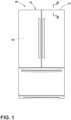
FIG. 1 is a front perspective view of a refrigerating appliance having a structural cabinet that incorporates an aspect of the trim breaker having the metal insert; -
FIG. 2 is a front perspective view of a structural cabinet for an appliance that incorporates an aspect of the trim breaker having the metal insert; -
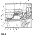
FIG. 3 is a cross-sectional view of the appliance ofFIG. 1 taken along line III-III;; -
FIG. 4 is a cross-sectional view of the trim breaker having an aspect of the metal insert; -
FIG. 5 is a schematic cross-sectional view of a mold used to form a trim breaker having a metal insert and showing placement of the metallic plate within the mold; -
FIG. 6 is a cross-sectional view of the mold ofFIG. 5 and showing movement of the injectable material within the mold; -
FIG. 7 is a cross-sectional view of the injection mold ofFIG. 6 and showing the injectable material surrounding the metallic plate; -
FIG. 8 is a cross-sectional view of an aspect of the trim breaker and showing a metallic plate completely embedded within the plastic material of the trim breaker; and -
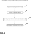
FIG. 9 is a schematic flow diagram illustrating a method for forming a trim breaker for a structural cabinet of an appliance. - The components in the figures are not necessarily to scale, emphasis instead being placed upon illustrating the principles described herein.
- The present illustrated embodiments reside primarily in combinations of method steps and apparatus components related to a trim breaker for an appliance cabinet having a metallic plate inserted therein. Accordingly, the apparatus components and method steps have been represented, where appropriate, by conventional symbols in the drawings, showing only those specific details that are pertinent to understanding the embodiments of the present disclosure so as not to obscure the disclosure with details that will be readily apparent to those of ordinary skill in the art having the benefit of the description herein. Further, like numerals in the description and drawings represent like elements.
- For purposes of description herein, the terms "upper," "lower," "right," "left," "rear," "front," "vertical," "horizontal," and derivatives thereof shall relate to the disclosure as oriented in
FIG. 1 . Unless stated otherwise, the term "front" shall refer to the surface of the element closer to an intended viewer, and the term "rear" shall refer to the surface of the element further from the intended viewer. However, it is to be understood that the disclosure may assume various alternative orientations, except where expressly specified to the contrary. It is also to be understood that the specific devices and processes illustrated in the attached drawings, and described in the following specification are simply exemplary embodiments of the inventive concepts defined in the appended claims. Hence, specific dimensions and other physical characteristics relating to the embodiments disclosed herein are not to be considered as limiting, unless the claims expressly state otherwise. - The terms "including," "comprises," "comprising," or any other variation thereof, are intended to cover a non-exclusive inclusion, such that a process, method, article, or apparatus that comprises a list of elements does not include only those elements but may include other elements not expressly listed or inherent to such process, method, article, or apparatus. An element proceeded by "comprises a . . . " does not, without more constraints, preclude the existence of additional identical elements in the process, method, article, or apparatus that comprises the element.
- With respect to
FIGS. 1-4 ,reference numeral 10 generally refers to a trim breaker that is incorporated within astructural cabinet 16 for anappliance 40. Thetrim breaker 10 extends between opposingmetallic plates 24, typically in the form of anouter wrapper 12 and aninner liner 14, that cooperate to form thestructural cabinet 16 having aninsulating cavity 18 defined therein. According to various aspects of the device, thestructural cabinet 16 can be in the form of a vacuum insulated structure that includes atrim breaker 10 having awrapper channel 20 and aliner channel 22 that extend perimetrically about thetrim breaker 10. Theinner liner 14 is attached to theliner channel 22 of thetrim breaker 10 and theouter wrapper 12 is attached to thetrim breaker 10 at thewrapper channel 20. Through this configuration, theinner liner 14, theouter wrapper 12 and thetrim breaker 10 cooperate to form the vacuum insulated structure. Ametallic plate 24 is disposed within thetrim breaker 10 and extends from afirst area 26 proximate theliner channel 22 to asecond area 28 proximate thewrapper channel 20. Themetallic plate 24, through this configuration, defines aninternal barrier 30 to gas permeation through thetrim breaker 10. - Within
structural cabinet 16, theinner liner 14 and theouter wrapper 12 can be made of a metallic material that is generally resistant to gas permeation therethrough. Thetrim breaker 10 that extends between theinner liner 14 and theouter wrapper 12 can be made of aplastic material 32. Plastic is generally a material that, by itself, allows gas to permeate therethrough. In the condition of a vacuum insulated structure, this gas permeation can, over time, allow gas to infiltrate into theinsulating cavity 18 and degrade the at leastpartial vacuum 70 that is defined within theinsulating cavity 18 of thestructural cabinet 16. The inclusion of themetallic plate 24 within thetrim breaker 10 reinforces thetrim breaker 10 and also provides an additionalinternal barrier 30 to gas permeation that can limit the amount of gas that can permeate through thetrim breaker 10 over time. Themetallic plate 24 can also slow the rate of gas permeation by a significant amount. This configuration can extend the life of the at leastpartial vacuum 70 within theinsulating cavity 18. In turn, this configuration can extend the life of anappliance 40 and the effectiveness and efficiency of theappliance 40 over its lifespan. - Referring again to
FIGS 1-4 , it is contemplated that thetrim breaker 10 includes aplastic material 32 that can be injection molded around themetallic plate 24. In this manner, themetallic plate 24 can be entirely encased within theplastic material 32 of thetrim breaker 10 as a single unitary piece. In such an embodiment, no portion of themetallic plate 24 is visible from theoutside surface 50 of thetrim breaker 10. Using this configuration, theinner liner 14 and theouter wrapper 12 are prevented from having any direct physical connection with themetallic plate 24. By separating themetallic plate 24 from theinner liner 14 and theouter wrapper 12, thermal conductivity through the metal components of thestructural cabinet 16 is prevented. At the same time, themetallic plate 24 and the metallic material of theinner liner 14 and theouter wrapper 12 provide a substantially continuous barrier to gas permeation around theinsulating cavity 18. The only gaps are defined by thespaces 52 between themetallic plate 24 and theinner liner 14 and theouter wrapper 12, respectively. - As exemplified in
FIGS. 5-7 , which illustrate a process for forming thetrim breaker 10, a portion of thetrim breaker 10 may be at least partially exposed within anoutside surface 50 of thetrim breaker 10. In such a configuration, anedge 60 of themetallic plate 24 may be co-planar with a plate-supportingportion 62 of thetrim breaker 10. This plate-supportingportion 62 of thetrim breaker 10 may be used to support themetallic plate 24 within amold 64 so thatinjectable material 66 that is injected into themold 64 and molded around themetallic plate 24 can be accurately positioned so that theinjectable material 66 surrounds the remaining portions of themetallic plate 24 other than theedge 60 of themetallic plate 24. In order to prevent theedge 60 of themetallic plate 24 from providing a path for thermal conduction or a significant path for gas permeation, theedge 60 of themetallic plate 24 and the plate-supportingportion 62 of thetrim breaker 10 can be positioned within a surface of thetrim breaker 10 that faces into the insulatingcavity 18 of thestructural cabinet 16. Through this configuration, theedge 60 of themetallic plate 24 is positioned adjacent to an insulatingmaterial 68 and exposed to the at leastpartial vacuum 70 maintained within the insulatingcavity 18. - As exemplified in
FIG. 8 , it is also contemplated that the entiremetallic plate 24 can be embedded within the material of thetrim breaker 10 so that themetallic plate 24 is completely surrounded by theinjectable material 66 and is not exposed to areas outside of thetrim breaker 10. - To achieve the positioning of the
metallic plate 24 within thetrim breaker 10, themetallic plate 24 can be insert injection molded within amold 64. Through this process, themetallic plate 24 can be positioned within themold 64 and can be positioned by one ormore pins 80, that position themetallic plate 24 within themold 64 so that themetallic plate 24 is supported in a consistent position as theinjectable material 66 flows around themetallic plate 24 to form the structure of thetrim breaker 10. - After the
trim breaker 10 is removed from themold 64, the voids left behind by the use of thepins 80 may be backfilled so that the entiremetallic plate 24 is surrounded by theplastic material 32 of thetrim breaker 10. As discussed above, the location of thepins 80 may also be oriented so that the voids within theplastic material 32 of thetrim breaker 10 left behind by the use of thepins 80 are located within, or exposed to, the insulatingcavity 18 for thestructural cabinet 16. In either instance, it should be understood that theinjectable material 66 of thetrim breaker 10 is intended to surround, or substantially surround, themetallic plate 24. By using the phrase "substantially surround," it should be understood that certain portions of thetrim breaker 10 may be exposed, such as theedge 60 of themetallic plate 24 or the location of the supportingpins 80 from themold 64, which may provide for a minimal exposure of themetallic plate 24 to areas outside of thetrim breaker 10. - Referring again to
FIGS 1-8 , in addition to themetallic plate 24 providing a barrier to gas permeation, theinjectable material 66 that surrounds themetallic plate 24 can also include materials that resist, or partially resist, gas permeation. In this manner, various aspects of the device can include gas-blockingflakes 90 that are incorporated within theinjectable material 66 of thetrim breaker 10. These gas-blockingflakes 90 can include mica, glass particles, or other similar naturally-occurring or manufactured particles that can be included within theinjectable material 66 to assist in preventing gas permeation through thetrim breaker 10. Where the gas-blockingflakes 90 are incorporated, theinjectable material 66, typically aplastic material 32, is a substantially homogenous mixture of theplastic material 32 and the gas-blockingflakes 90. The substantial homogeneity of theinjectable material 66 is achieved through the size of the gas-blockingflakes 90 being substantially microscopic, such that each particle of the gas-blockingflakes 90 has a dimension in the order of microns. The small size of these gas-blockingflakes 90 make them substantially imperceptible with a naked eye when mixed with aninjectable material 66. Accordingly, the substantial homogeneity of theinjectable material 66 can be achieved when the gas-blockingflakes 90 are incorporated within theplastic material 32 of theinjectable material 66. - Referring again to
FIGS. 3-8 , thetrim breaker 10 that can be used within vacuum insulated structures, such as thestructural cabinet 16 described herein, can include aplastic body 100 that defines thewrapper channel 20 and theliner channel 22. A plurality of gas-blockingflakes 90 are disposed throughout the material of theplastic body 100. Themetallic plate 24 is disposed entirely within thetrim breaker 10 and extends from thefirst area 26 proximate theliner channel 22 to thesecond area 28 proximate thewrapper channel 20. The first andsecond areas metallic plate 24 extends are areas within an interior of thetrim breaker 10. - As exemplified in
FIGS. 4 ,7 and8 , thefirst area 26 proximate theliner channel 22 is within a portion of thetrim breaker 10 that defines theliner channel 22. Thisfirst area 26, as with themetallic plate 24, is positioned entirely within the material of thetrim breaker 10. Accordingly, thefirst edge 102 of themetallic plate 24 is located at thisfirst area 26 proximate theliner channel 22 and is typically entirely encased within thetrim breaker 10. As discussed above, in certain aspects of the device, thefirst edge 102, or a portion of thefirst edge 102 of themetallic plate 24, can be co-planar with the plate-supportingportion 62 of thetrim breaker 10, such that thefirst edge 102 of themetallic plate 24, or a portion thereof, is exposed to the exterior of thetrim breaker 10, but is located within the insulatingcavity 18 for thestructural cabinet 16. Thesecond edge 104 of thetrim breaker 10 is positioned within thesecond area 28 that is positioned proximate thewrapper channel 20. Thissecond area 28 is configured to be located within an interior portion of thetrim breaker 10 and within theinjectable material 66. Through this configuration, thesecond edge 104 of themetallic plate 24 that is located at thissecond area 28 is also entirely encased within the material of thetrim breaker 10. - In various aspects of the device, it is contemplated that the
first edge 102 and/or thesecond edge 104 of thetrim breaker 10 can wrap at least partially around thewrapper channel 20 and theliner channel 22, respectively. As exemplified inFIG. 7 , thesecond edge 104 of themetallic plate 24 wraps partially around thewrapper channel 20. The location of themetallic plate 24 relative to thewrapper channel 20 and theliner channel 22 are configured to provide a substantially continuous barrier to gas permeation. Through this configuration, themetallic plate 24 is configured to cooperate with the metallic material of theinner liner 14 and theouter wrapper 12 to provide the substantially continuous barrier to gas permeation. - As exemplified in
FIGS. 3-8 , thewrapper channel 20 is configured to receive and secure the metallicouter wrapper 12, typically via an adhesive 110. Themetallic plate 24 is separated from the metallicouter wrapper 12 at least by a portion of theplastic body 100 for thetrim breaker 10. Similarly, theliner channel 22 receives and secures the metallicinner liner 14, typically via the adhesive 110. Themetallic plate 24 is separated from the metallicinner liner 14 at least by a portion of theplastic body 100. As discussed above, theplastic body 100 includes theplastic material 32 and, in certain configurations, the gas-blockingflakes 90, that form the homogenous material, or substantially homogenous material, that is injection molded around themetallic plate 24 as a homogenousinjectable material 66. - Referring again to
FIGS. 1-8 , the vacuum insulated structure can include thetrim breaker 10 having thewrapper channel 20 and theliner channel 22. Theinner liner 14 is attached to thetrim breaker 10 at theliner channel 22 and theouter wrapper 12 is attached to thetrim breaker 10 at thewrapper channel 20. Themetallic plate 24 is insert injection-molded within thetrim breaker 10 and extends from afirst area 26 proximate theliner channel 22 to asecond area 28 proximate thewrapper channel 20. As discussed above, themetallic plate 24 defines aninternal barrier 30 to gas permeation through thetrim breaker 10. Typically, themetallic plate 24 is made of steel, a steel alloy, or other similar metallic material that is resistive to gas permeation. - According to various aspects of the device, the
plastic material 32 of thetrim breaker 10 can include various plastic-type materials that can include any one of various plastic-type materials such as polymers, composite materials, and combinations thereof. Such exemplaryplastic materials 32 can include, but are not limited to, polyvinyl chloride (PVC), polyethylene terephthalate (PET) that is at least partially glass-filled, various polyester materials, various copolyester materials, and other similar polymers. Additionally, theoutside surface 50 of thetrim breaker 10 that is exposed to the insulatingcavity 18 can be coated withvarious coating materials 116 that can include, but are not limited to, aluminum silicate (AL SiO2,) titanium coatings, and othersimilar coating materials 116. As discussed above, the gas-blockingflakes 90 can include mica, glass and other similar materials. These gas-blockingflakes 90 can be incorporated within thetrim breaker 10 at various amounts. By way of example, and not limitation, theinjectable material 66 for thetrim breaker 10 can include a range of from approximately 5% to approximately 25% of the gas-blockingflakes 90, by volume. Other percentages of the gas-blockingflakes 90 can be incorporated depending upon the size of the particles of gas-blockingflakes 90, the weight of the gas-blockingflakes 90 and the individual characteristics that form the material of the gas-blockingflakes 90. - Referring now to
FIGS. 1-9 , having described various aspects of thetrim breaker 10 that includes themetallic plate 24, amethod 400 is disclosed for forming atrim breaker 10 having an aspect of themetallic plate 24. According to themethod 400, ametallic plate 24 is disposed within the mold 64 (step 402). As discussed previously, themetallic plate 24 can be held in place throughvarious pins 80 that are incorporated within themold 64 or through the plate-supportingportion 62 for thetrim breaker 10. According to themethod 400, theinjectable material 66 is formed (step 404). As discussed above, theinjectable material 66 can include plastic and a plurality of gas-blockingflakes 90. After forming theinjectable material 66, theinjectable material 66 is injected into themold 64 and around the metallic plate 24 (step 406). Thisinjectable material 66 is then cooled and solidified around themetallic plate 24 to form a unitary assembly with themetallic plate 24 embedded therein. Thetrim breaker 10 can then be removed from the mold 64 (step 408). As discussed herein, themetallic plate 24 is encased, or substantially encased, within thetrim breaker 10. - As exemplified in
FIGS. 5-7 , an aspect of themethod 400 for forming thetrim breaker 10 can include attaching themetallic plate 24 to asupport section 120 that supports themetallic plate 24 relative to themold 64. After theinjectable material 66 is injected into themold 64 and is solidified, thetrim breaker 10 can be removed from themold 64. Any excess portion of themetallic plate 24 that may extend from thetrim breaker 10 can be removed through cutting, grinding, or other similar process for eliminating excess portions of themetallic plate 24 that may extend from the plate-supportingportion 62 of thetrim breaker 10. As discussed above, any portion of themetallic plate 24 that is exposed to the outside of thetrim breaker 10 can be positioned within the insulatingcavity 18. Additionally, these exposed portions can be covered with at least a portion of theplastic material 32, coatings, and other gas-permeation resistive materials described herein. - According to various aspects of the device, the
metallic plate 24 set within thetrim breaker 10 is used to prevent gas permeation through thetrim breaker 10 that might cause a degradation of an at leastpartial vacuum 70 within an insulatingcavity 18. This barrier to gas permeation can also be used to maintain insulating gasses within the insulatingcavity 18 and prevent leakage of these insulating gasses outside of the insulatingcavity 18 of thestructural cabinet 16. These insulating gasses can include, but are not limited to, carbon dioxide, various inert gasses, and other similar gasses that are typically used within insulating structures. - The
trim breaker 10 having themetallic plate 24 incorporated therein can be used withinvarious appliances 40.Such appliances 40 can include, but are not limited to, refrigerators, freezers, coolers, laundry appliances, ovens, water heaters, small appliances, and other similar appliances and fixtures that may require a pressure differential between the atmosphere and an interior insulatingcavity 18. - According to another aspect of the present disclosure, a vacuum insulated structure includes a trim breaker having a wrapper channel and a liner channel that extend perimetrically about the trim breaker. An inner liner is attached to the trim breaker at the liner channel. An outer wrapper is attached to the trim breaker at the wrapper channel. A metallic plate is disposed within the trim breaker and extends from a first area proximate the liner channel to a second area proximate the wrapper channel. The metallic plate defines an internal barrier to gas permeation through the trim breaker.
- According to another aspect, the trim breaker includes gas-blocking flakes that are incorporated throughout the trim breaker.
- According to yet another aspect, the trim breaker includes a plastic material and the gas-blocking flakes as a homogenous material.
- According to another aspect, the trim breaker is an injection molded piece, wherein the homogenous material is injection molded around the metallic plate.
- According to yet another aspect, the metallic plate is entirely encased within the homogenous material of the trim breaker.
- According to another aspect of the present disclosure, the metallic plate is separated from the inner liner and the outer wrapper at least by a plastic material of the trim breaker, wherein the plastic material substantially surrounds the metallic plate.
- According to another aspect, an edge of the metallic plate is co-planar with a plate-supporting portion of the trim breaker, wherein the plate-supporting portion of the trim breaker is positioned within an insulating cavity defined between the inner liner, the outer wrapper and the trim breaker.
- According to yet another aspect, the gas-blocking flakes are at least one of mica and glass.
- According to another aspect of the present disclosure, the metallic plate is insert injection molded within the trim breaker.
- According to another aspect, a trim breaker for a vacuum insulated structure includes a plastic body that defines a wrapper channel and a liner channel. A plurality of gas-blocking flakes are disposed throughout the plastic body. A metallic plate is disposed entirely within the trim breaker and extends from a first area proximate the liner channel to a second area proximate the wrapper channel.
- According to yet another aspect, the wrapper channel receives a metallic wrapper that is secured within the wrapper channel, and wherein the metallic plate is separated from the metallic wrapper at least by a portion of the plastic body.
- According to another aspect of the present disclosure, the liner channel receives a metallic liner that is secured within the liner channel, and wherein the metallic plate is separated from the metallic liner at least by a portion of the plastic body.
- According to another aspect, the material of the plastic body and the gas-blocking flakes are injection molded around the metallic plate as a homogenous injectable material.
- According to yet another aspect, the gas-blocking flakes are at least one of mica and glass.
- According to another aspect of the present disclosure, a vacuum insulated structure includes a trim breaker having a wrapper channel and a liner channel. An inner liner is attached to the trim breaker at the liner channel. An outer wrapper is attached to the trim breaker at the wrapper channel. A metallic plate is insert injection molded within the trim breaker and extends from a first area proximate the liner channel to a second area proximate the wrapper channel. The metallic plate defines an internal barrier to gas permeation through the trim breaker.
- According to another aspect, the trim breaker includes gas-blocking flakes that are incorporated within an injectable material of the trim breaker, wherein the injectable material is a substantially homogenous material.
- According to yet another aspect, the metallic plate is entirely encased within the substantially homogenous material of the trim breaker.
- According to another aspect of the present disclosure, an edge of the metallic plate is co-planar with a plate-supporting portion of the trim breaker. The plate-supporting portion of the trim breaker is positioned within an insulating cavity defined between the inner liner, the outer wrapper and the trim breaker.
- According to another aspect, the gas-blocking flakes are at least one of mica and glass.
- According to another aspect of the present disclosure, the metallic plate is steel.
Claims (13)
- A vacuum insulated structure comprising:a trim breaker (10) having a wrapper channel (20) and a liner channel (22) that extend perimetrically about the trim breaker (10);an inner liner (14) attached to the trim breaker (10) at the liner channel (22);an outer wrapper (12) attached to the trim breaker (10) at the wrapper channel (20); anda metallic plate (24) disposed within the trim breaker (10) and extending from a first area (26) proximate the liner channel (22) to a second area (28) proximate the wrapper channel (20), the metallic plate (24) defining an internal barrier (30) to gas permeation through the trim breaker (10).
- The vacuum insulated structure of claim 1, wherein the trim breaker (10) includes gas-blocking flakes (90) that are incorporated throughout the trim breaker (10).
- The vacuum insulated structure of claim 2, wherein the trim breaker (10) includes a plastic material (32) and the gas-blocking flakes (90) as a homogenous material.
- The vacuum insulated structure of claim 3, wherein the trim breaker (10) is an injection molded piece that is attached to the metallic plate (24).
- The vacuum insulated structure of claim 4, wherein the homogenous material is injection molded around the metallic plate (24).
- The vacuum insulated structure of any one of claims 3-5, wherein the metallic plate (24) is entirely encased within the homogenous material of the trim breaker (10).
- The vacuum insulated structure of any one of claims 1-6, wherein the metallic plate (24) is separated from the inner liner (14) and the outer wrapper (12) at least by a plastic material (32) of the trim breaker (10).
- The vacuum insulated structure of claim 7, wherein the plastic material (32) substantially surrounds the metallic plate (24).
- The vacuum insulated structure of any one of claims 1-8, wherein an edge of the metallic plate (24) is co-planar with a plate-supporting portion (62) of the trim breaker (10).
- The vacuum insulated structure of claim 9, wherein the plate-supporting portion (62) of the trim breaker (10) is positioned within an insulating cavity (18) defined between the inner liner (14), the outer wrapper (12) and the trim breaker (10).
- The vacuum insulated structure of any one of claims 2-10, wherein the gas-blocking flakes (90) are made of mica.
- The vacuum insulated structure of any one of claims 2-10, wherein the gas-blocking flakes (90) are made of glass.
- The vacuum insulated structure of any one of claims 3-12, wherein the homogenous material includes approximately 5% to approximately 25% of the gas-blocking flakes (90), by volume.
Applications Claiming Priority (1)
| Application Number | Priority Date | Filing Date | Title |
|---|---|---|---|
| US17/477,094 US11858235B2 (en) | 2021-09-16 | 2021-09-16 | Trim breaker having metallic insert for decreased gas permeation |
Publications (1)
| Publication Number | Publication Date |
|---|---|
| EP4151939A1 true EP4151939A1 (en) | 2023-03-22 |
Family
ID=82701962
Family Applications (1)
| Application Number | Title | Priority Date | Filing Date |
|---|---|---|---|
| EP22186361.6A Withdrawn EP4151939A1 (en) | 2021-09-16 | 2022-07-21 | Trim breaker having metallic insert for decreased gas permeation |
Country Status (3)
| Country | Link |
|---|---|
| US (2) | US11858235B2 (en) |
| EP (1) | EP4151939A1 (en) |
| CN (1) | CN115823814A (en) |
Families Citing this family (1)
| Publication number | Priority date | Publication date | Assignee | Title |
|---|---|---|---|---|
| CN118438604B (en) * | 2023-10-30 | 2025-02-11 | 荣耀终端有限公司 | Insert injection mold, insert injection structure and preparation method thereof, camera module |
Citations (4)
| Publication number | Priority date | Publication date | Assignee | Title |
|---|---|---|---|---|
| US20020041134A1 (en) * | 1999-02-19 | 2002-04-11 | Ulrich Wolf | Heat-insulating wall |
| US20200132359A1 (en) * | 2018-10-31 | 2020-04-30 | Whirlpool Corporation | Polymer trim breaker having gas-blocking flakes and an epoxy coating |
| US20210199368A1 (en) * | 2019-12-30 | 2021-07-01 | Whirlpool Corporation | Trim breaker for an insulated appliance |
| US20210231361A1 (en) * | 2020-01-23 | 2021-07-29 | Bsh Home Appliances Corporation | Extruded plastic front frame profiles for cooling appliances |
Family Cites Families (9)
| Publication number | Priority date | Publication date | Assignee | Title |
|---|---|---|---|---|
| US2259185A (en) * | 1937-10-20 | 1941-10-14 | Seeger Refrigerator Co | Refrigerator cabinet |
| US2715976A (en) | 1952-04-28 | 1955-08-23 | Motor Products Corp | Breaker strip assembly |
| US2792959A (en) | 1953-09-28 | 1957-05-21 | Whirlpool Seeger Corp | Plastic breaker strip construction |
| US3167821A (en) * | 1962-12-17 | 1965-02-02 | Philco Corp | Cabinet structure |
| US5476318A (en) | 1994-09-08 | 1995-12-19 | Traulsen & Co. Inc. | Regrigerator/freezer thermal breaker and door handle |
| GB0019596D0 (en) * | 2000-08-09 | 2000-09-27 | Foster Refrigerator Uk Ltd | Refrigeration cabinet |
| US20090031659A1 (en) | 2005-01-24 | 2009-02-05 | Rami Abraham Kalfon | Evacuated Thermal Insulation Panel |
| WO2018022006A1 (en) | 2016-07-26 | 2018-02-01 | Whirlpool Corporation | A method for manufacturing an insulated structure for a refrigerator |
| US11340008B1 (en) * | 2021-01-20 | 2022-05-24 | Whirlpool Corporation | Appliance trim breaker assembly |
-
2021
- 2021-09-16 US US17/477,094 patent/US11858235B2/en active Active
-
2022
- 2022-07-21 EP EP22186361.6A patent/EP4151939A1/en not_active Withdrawn
- 2022-09-16 CN CN202211129510.XA patent/CN115823814A/en active Pending
-
2023
- 2023-10-25 US US18/493,902 patent/US20240051268A1/en not_active Abandoned
Patent Citations (4)
| Publication number | Priority date | Publication date | Assignee | Title |
|---|---|---|---|---|
| US20020041134A1 (en) * | 1999-02-19 | 2002-04-11 | Ulrich Wolf | Heat-insulating wall |
| US20200132359A1 (en) * | 2018-10-31 | 2020-04-30 | Whirlpool Corporation | Polymer trim breaker having gas-blocking flakes and an epoxy coating |
| US20210199368A1 (en) * | 2019-12-30 | 2021-07-01 | Whirlpool Corporation | Trim breaker for an insulated appliance |
| US20210231361A1 (en) * | 2020-01-23 | 2021-07-29 | Bsh Home Appliances Corporation | Extruded plastic front frame profiles for cooling appliances |
Also Published As
| Publication number | Publication date |
|---|---|
| US20230080063A1 (en) | 2023-03-16 |
| US11858235B2 (en) | 2024-01-02 |
| CN115823814A (en) | 2023-03-21 |
| US20240051268A1 (en) | 2024-02-15 |
Similar Documents
| Publication | Publication Date | Title |
|---|---|---|
| US11466927B2 (en) | Hermetically sealed overmolded plastic thermal bridge breaker with refrigerator cabinet liner and wrapper for vacuum insulation | |
| US10612834B2 (en) | Method for manufacturing an insulated structure for a refrigerator | |
| EP3491308B1 (en) | Vacuum insulated structure trim breaker | |
| US20240051268A1 (en) | Trim breaker having metallic insert for decreased gas permeation | |
| US20210356195A1 (en) | Vacuum insulated structure with thermal bridge breaker with heat loop | |
| JPH09166271A (en) | Vacuum insulation panel mounting structure and vacuum insulation panel for heat insulation wall surface | |
| EP3397906B1 (en) | Injection molded gas barrier parts for vacuum insulated structure | |
| US20210199368A1 (en) | Trim breaker for an insulated appliance | |
| CN108613464A (en) | Refrigerating appliance and its insulated door | |
| US10907891B2 (en) | Trim breaker for a structural cabinet that incorporates a structural glass contact surface | |
| KR20200001363A (en) | Vacuum adiabatic body and refrigerator | |
| US5876104A (en) | Breaker assembly for refrigerated cabinet | |
| AU2014227300B2 (en) | Cooling box | |
| JP6622406B2 (en) | Insulated box and freezer | |
| KR200474628Y1 (en) | Refrigerator | |
| KR101423521B1 (en) | Apparatus for processing substrate | |
| KR20210078841A (en) | Vacuum adiabatic body and refrigerator | |
| JP2019132499A (en) | refrigerator | |
| KR100664279B1 (en) | Vacuum insulator for refrigerator cabinet, manufacturing method thereof and insulation structure of refrigerator cabinet to which it is applied | |
| CN116926669B (en) | Sapphire armor plate preparation mold, preparation device and manufacturing process | |
| US20240271859A1 (en) | Vacuum insulated structure with thermal bridge breaker with heat loop | |
| KR20210078842A (en) | Vacuum adiabatic body and refrigerator | |
| JPH01150782A (en) | Refrigerator | |
| RU2654745C2 (en) | Vacuum insulation body | |
| JP6972300B2 (en) | Insulated box |
Legal Events
| Date | Code | Title | Description |
|---|---|---|---|
| PUAI | Public reference made under article 153(3) epc to a published international application that has entered the european phase |
Free format text: ORIGINAL CODE: 0009012 |
|
| STAA | Information on the status of an ep patent application or granted ep patent |
Free format text: STATUS: THE APPLICATION HAS BEEN PUBLISHED |
|
| AK | Designated contracting states |
Kind code of ref document: A1 Designated state(s): AL AT BE BG CH CY CZ DE DK EE ES FI FR GB GR HR HU IE IS IT LI LT LU LV MC MK MT NL NO PL PT RO RS SE SI SK SM TR |
|
| STAA | Information on the status of an ep patent application or granted ep patent |
Free format text: STATUS: REQUEST FOR EXAMINATION WAS MADE |
|
| P01 | Opt-out of the competence of the unified patent court (upc) registered |
Effective date: 20230920 |
|
| 17P | Request for examination filed |
Effective date: 20230922 |
|
| RBV | Designated contracting states (corrected) |
Designated state(s): AL AT BE BG CH CY CZ DE DK EE ES FI FR GB GR HR HU IE IS IT LI LT LU LV MC MK MT NL NO PL PT RO RS SE SI SK SM TR |
|
| GRAP | Despatch of communication of intention to grant a patent |
Free format text: ORIGINAL CODE: EPIDOSNIGR1 |
|
| STAA | Information on the status of an ep patent application or granted ep patent |
Free format text: STATUS: GRANT OF PATENT IS INTENDED |
|
| RIC1 | Information provided on ipc code assigned before grant |
Ipc: F25D 23/08 20060101AFI20250210BHEP |
|
| INTG | Intention to grant announced |
Effective date: 20250219 |
|
| STAA | Information on the status of an ep patent application or granted ep patent |
Free format text: STATUS: THE APPLICATION IS DEEMED TO BE WITHDRAWN |
|
| 18D | Application deemed to be withdrawn |
Effective date: 20250621 |