EP4151934A1 - Vertical door system and refrigerator cabinet provided with such a vertical door system - Google Patents
Vertical door system and refrigerator cabinet provided with such a vertical door system Download PDFInfo
- Publication number
- EP4151934A1 EP4151934A1 EP21197322.7A EP21197322A EP4151934A1 EP 4151934 A1 EP4151934 A1 EP 4151934A1 EP 21197322 A EP21197322 A EP 21197322A EP 4151934 A1 EP4151934 A1 EP 4151934A1
- Authority
- EP
- European Patent Office
- Prior art keywords
- door
- vertical
- door system
- extreme position
- hinge
- Prior art date
- Legal status (The legal status is an assumption and is not a legal conclusion. Google has not performed a legal analysis and makes no representation as to the accuracy of the status listed.)
- Withdrawn
Links
- 238000010008 shearing Methods 0.000 claims abstract description 6
- 238000009413 insulation Methods 0.000 description 4
- 230000002159 abnormal effect Effects 0.000 description 1
- 230000005484 gravity Effects 0.000 description 1
- 238000003780 insertion Methods 0.000 description 1
- 230000037431 insertion Effects 0.000 description 1
- 238000004519 manufacturing process Methods 0.000 description 1
- 238000005259 measurement Methods 0.000 description 1
- 229920001296 polysiloxane Polymers 0.000 description 1
Images




Classifications
-
- F—MECHANICAL ENGINEERING; LIGHTING; HEATING; WEAPONS; BLASTING
- F25—REFRIGERATION OR COOLING; COMBINED HEATING AND REFRIGERATION SYSTEMS; HEAT PUMP SYSTEMS; MANUFACTURE OR STORAGE OF ICE; LIQUEFACTION SOLIDIFICATION OF GASES
- F25D—REFRIGERATORS; COLD ROOMS; ICE-BOXES; COOLING OR FREEZING APPARATUS NOT OTHERWISE PROVIDED FOR
- F25D23/00—General constructional features
- F25D23/02—Doors; Covers
- F25D23/028—Details
-
- F—MECHANICAL ENGINEERING; LIGHTING; HEATING; WEAPONS; BLASTING
- F25—REFRIGERATION OR COOLING; COMBINED HEATING AND REFRIGERATION SYSTEMS; HEAT PUMP SYSTEMS; MANUFACTURE OR STORAGE OF ICE; LIQUEFACTION SOLIDIFICATION OF GASES
- F25D—REFRIGERATORS; COLD ROOMS; ICE-BOXES; COOLING OR FREEZING APPARATUS NOT OTHERWISE PROVIDED FOR
- F25D23/00—General constructional features
- F25D23/08—Parts formed wholly or mainly of plastics materials
- F25D23/082—Strips
- F25D23/087—Sealing strips
-
- F—MECHANICAL ENGINEERING; LIGHTING; HEATING; WEAPONS; BLASTING
- F25—REFRIGERATION OR COOLING; COMBINED HEATING AND REFRIGERATION SYSTEMS; HEAT PUMP SYSTEMS; MANUFACTURE OR STORAGE OF ICE; LIQUEFACTION SOLIDIFICATION OF GASES
- F25D—REFRIGERATORS; COLD ROOMS; ICE-BOXES; COOLING OR FREEZING APPARATUS NOT OTHERWISE PROVIDED FOR
- F25D2323/00—General constructional features not provided for in other groups of this subclass
- F25D2323/02—Details of doors or covers not otherwise covered
- F25D2323/021—French doors
-
- F—MECHANICAL ENGINEERING; LIGHTING; HEATING; WEAPONS; BLASTING
- F25—REFRIGERATION OR COOLING; COMBINED HEATING AND REFRIGERATION SYSTEMS; HEAT PUMP SYSTEMS; MANUFACTURE OR STORAGE OF ICE; LIQUEFACTION SOLIDIFICATION OF GASES
- F25D—REFRIGERATORS; COLD ROOMS; ICE-BOXES; COOLING OR FREEZING APPARATUS NOT OTHERWISE PROVIDED FOR
- F25D2323/00—General constructional features not provided for in other groups of this subclass
- F25D2323/02—Details of doors or covers not otherwise covered
- F25D2323/024—Door hinges
Definitions
- the invention refers to a vertical door system, in particular a vertical door system for a refrigerator cabinet, as well as to a refrigerator cabinet provided with such a vertical door system.
- Vertical door systems are used in the manufacturing of refrigerator cabinets that are used for the storage and the display of perishable products available for sale.
- Prior art document EP2908073A1 discloses an improved hinge group for a refrigerator cabinet vertical door system that enables limiting the non-transparent area of the door and also reducing the interspace between the closing panel and the fixed frame of the door (so as to prevent the possibility of insertion of fingers in the space), enabling at the same time a large number of openings and closings of the closing panel without wearing the cam means, as well as a good level of silent operation.
- Prior art document US2019/0059613A1 discloses a refrigerator cabinet provided with hinges that may be of the torque, gravity, or electrical type.
- the disadvantage of the prior art embodiments is that none of them is provided with a hinge safety mechanism. In case the door is opened (for example at an angle larger than 90°) by using excessive force, the hinge and possibly the cabinet frame will be damaged and will need replacement, thus leading to an expensive, time-consuming operation.
- the present invention aims to eliminate the afore-mentioned disadvantage, by using a vertical door system provided with a simple and inexpensive hinge safety system.
- Another goal of the present invention is to provide a simple and inexpensive solution that enhances the thermal insulation of the interior of the refrigerator cabinet.
- the vertical door system according to the invention comprises:
- the force threshold value is within the range 800 N ⁇ 1200 N, preferably within the range 900 N ⁇ 1100 N.
- the vertical door system further comprises a lateral gasket, fixed along the length of a vertical side of the door that is distal in respect to the upper and lower hinges.
- the lateral gasket is made of a flexible material and has the shape of letter T rotated at an angle of 90 degrees.
- the lower hinge is a gravitational hinge or a hydraulic hinge.
- the angle formed by the door between its first extreme position and its second extreme position is 110°.
- a single-door refrigerator cabinet is provided with a vertical door system according to the invention.
- a two-doors refrigerator cabinet is provided with two vertical door systems according to the invention, wherein, when the respective doors are simultaneously in their first extreme position, the doors lie in the same plane and the respective lateral gaskets are in mutual contact and overlap along their entire length.
- the vertical door system according to the invention provides the advantage of a simple and inexpensive hinge safety system: the single part that has to be replaced is the safety screw. Moreover, until the screw is replaced, the door can work normally and the refrigerator cabinet can be kept in operation (i.e. no need to be disconnected from power until the safety screw is replaced).
- Another advantage of the invention is that it provides increased thermal insulation by means of a door lateral flexible gasket of a particular shape.
- Figure 1 shows a front view of a prior art refrigerator cabinet provided with two conventional vertical doors.
- the vertical door system according to the invention is fully compatible with any type of prior art refrigerator cabinet (i.e. the conventional vertical doors of the prior art refrigerator cabinet can be dismounted and replaced with a vertical door system according to the invention).
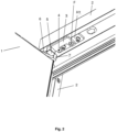
- FIG. 2 shows the upper part of the vertical door system according to the invention: a door 1 is attached to a frame 2 by means of and an upper hinge H1 provided at the upper left corner of the door 1 and of a lower hinge (not represented in Figure 2 ) provided at the lower left corner of the door 1.
- the door 1 is of a type that is commonly used for refrigerator cabinets.
- the door 1 is capable to move, in respect to the frame 2, between a first extreme position (closed position) and a second extreme position (open to the maximum position), by means of the upper H1 and lower H2 hinges.
- the frame 2 is designed to be further fixed to a refrigerator cabinet (not represented in Figure 2 ).
- a first plate 3 is fixed to the upper hinge H1 by means of a safety screw 4 and of a fixing screw F.
- the safety screw 4 and the fixing screw F are not screwed in the frame 2.
- the upper hinge H1 is fixed to the frame 2 by means of two further screws (i.e. other than the safety and fixing screws).
- the first plate 3 is provided with a stopper 5.
- the stopper 5 is situated at an extremity of the first plate 3 that is proximal to the left side of the door 1.
- the stopper 5 is a protuberance that is preferably integral with the first plate 2.
- a second plate 6 is fixed to the upper left corner of the door 1 and is provided with a nose 7 positioned such that the nose 7 is in contact with the stopper 5 only when the door 1 is in its second extreme position.
- the nose 7 is a protuberance that is preferably integral with the second plate 6.
- Both the stopper 5 and the nose 7 have preferably a parallelepipedic shape with rounded edges. However, they both may have any other adequate shape, such as a cube, a truncated pyramid, a truncated cone, etc.
- the safety screw 4 has a shearing resistance such that the safety screw 4 breaks when a force applied by the nose 7 to the stopper 5 exceeds a threshold value.
- a threshold value When a user opens the door 1 and tries to open it at a greater angle than the one normally allowed by the nose 7 + stopper 5 configuration (i.e. beyond the door 1 second extreme position), the nose 7 contacts and applies a force to the stopper 5. If said force exceeds a threshold value, the safety screw 4 breaks because it is subjected to a shearing stress that exceeds its shearing resistance.
- the vertical door system shows only one door 1.
- said cabinet will be provided with two vertical door systems (each system associated to its respective door).
- Figure 3 shows the door 1 in its first extreme position (the closed position) while Figure 4 shows the door 1 in its second extreme position (the open to the maximum position).
- the safety screw 4 and the fixing screw F are not visible.
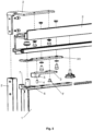
- Figure 5 shows in detail the exploded view of the upper part of the vertical door system.
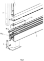
- FIG. 6 shows in detail the exploded view of the lower part of the vertical door system.
- the lower hinge H2 was represented as a hydraulic hinge. In practice, the lower hinge H2 may also be a gravitational hinge.
- FIGS 5 and 6 in order to avoid the overcrowding of the drawings, reference numbers were assigned only to the essential parts of the door system.
- the parts that do not bear a reference number are simple known connecting elements (i.e. screws, washers, bushings, etc.) that are commonly used in the art.
- the frame 2 consists of a plurality of parts (lateral parts, corner parts, upper and lower parts) assembled together by means of connecting elements.
- the upper H1 and lower H2 hinges are also known types of hinges, and consist, each, of a plurality of parts (plate, pin, bushing, bearing, etc) assembled together. Only for simplicity reason the references H1 and H2 in figures 2 , 5 , 6 , and 8 indicate only one part of the respective hinge.
- Figure 7 shows a latelal (profile) view of the vertical door system.
- the door 1 is provided with a handle 8.
- a user can open or close the door 1 by pulling or respectively pushing the handle 8.
- Figure 8 shows a detail of the upper part of Figure 7 .
- the door 1 is in its first extreme position (closed position) wherein a gap between the stopper 5 and the nose 7 is clearly visible (the stopper 5 and the nose 7 are not in contact).
- FIG 9 shows a view from above of a central zone of a two-doors refrigerator cabinet provided with the vertical door system (in fact, one door system for each door).
- the doors 1 of the refrigerator cabinet lie in the same plane when they are in their closed position.
- Each door 1 is provided with a handle 8 and with a lateral gasket G made of a flexible material, and fixed along the length of a vertical side of the door 1 that is distal in respect to the associated upper and lower hinges (not shown in Figure 9 ).
- the two lateral gaskets G are in mutual contact and overlap along their entire length, fact that provides an enhanced thermal insulation of the interior of the refrigerator cabinet.
- each lateral gasket G corresponds substantially to the height of the associated door 1.
- the gasket G can be made of rubber, silicone or any other suitable heat-insulating flexible material.
- FIG 10 shows, at a greater scale, the lateral gaskets G from Figure 9 .
- Each lateral gasket G has the shape of letter "T" rotated at a 90° angle. When both doors are in their closed position, the two lateral gaskets G are approximately symmetrically arranged. This particular shape and arrangement of the lateral gaskets G ensure the maximization of the overlapping area A, fact that further enhances the thermal insulation of the interior of the refrigerator cabinet.
- Figure 11 shows a front view of the left lateral gasket G of Figure 10 , where the overlapping area A is clearly visible.
Landscapes
- Engineering & Computer Science (AREA)
- Chemical & Material Sciences (AREA)
- Combustion & Propulsion (AREA)
- Physics & Mathematics (AREA)
- Mechanical Engineering (AREA)
- Thermal Sciences (AREA)
- General Engineering & Computer Science (AREA)
- Refrigerator Housings (AREA)
Abstract
Description
- The invention refers to a vertical door system, in particular a vertical door system for a refrigerator cabinet, as well as to a refrigerator cabinet provided with such a vertical door system.
- Vertical door systems are used in the manufacturing of refrigerator cabinets that are used for the storage and the display of perishable products available for sale.
- Prior art document
EP2908073A1 discloses an improved hinge group for a refrigerator cabinet vertical door system that enables limiting the non-transparent area of the door and also reducing the interspace between the closing panel and the fixed frame of the door (so as to prevent the possibility of insertion of fingers in the space), enabling at the same time a large number of openings and closings of the closing panel without wearing the cam means, as well as a good level of silent operation. - Prior art document
US2019/0059613A1 discloses a refrigerator cabinet provided with hinges that may be of the torque, gravity, or electrical type. - The disadvantage of the prior art embodiments is that none of them is provided with a hinge safety mechanism. In case the door is opened (for example at an angle larger than 90°) by using excessive force, the hinge and possibly the cabinet frame will be damaged and will need replacement, thus leading to an expensive, time-consuming operation.
- The present invention aims to eliminate the afore-mentioned disadvantage, by using a vertical door system provided with a simple and inexpensive hinge safety system. Another goal of the present invention is to provide a simple and inexpensive solution that enhances the thermal insulation of the interior of the refrigerator cabinet.
- The vertical door system according to the invention comprises:
- a door attached to a frame by means of an upper hinge provided at an upper corner of the door and of a lower hinge provided at a lower corner of the door,
- the upper and lower hinges allowing the door to move, in respect to the frame, between a first extreme position and a second extreme position,
- a first plate fixed to the upper hinge by means of a safety screw and of a fixing screw, and provided with a stopper,
- a second plate fixed to the upper corner of the door and provided with a nose positioned such that the nose is in contact with the stopper only when the door is in its second extreme position,
- the safety screw has a shearing resistance such that the safety screw breaks when a force applied by the nose to the stopper exceeds a threshold value.
- In a preferred embodiment, the force threshold value is within the range 800 N ÷ 1200 N, preferably within the range 900 N ÷ 1100 N.
- In a preferred embodiment, the vertical door system further comprises a lateral gasket, fixed along the length of a vertical side of the door that is distal in respect to the upper and lower hinges.
- In a preferred embodiment, the lateral gasket is made of a flexible material and has the shape of letter T rotated at an angle of 90 degrees.
- In a preferred embodiment, the lower hinge is a gravitational hinge or a hydraulic hinge.
- In a preferred embodiment the angle formed by the door between its first extreme position and its second extreme position is 110°.
- In a preferred embodiment, a single-door refrigerator cabinet is provided with a vertical door system according to the invention.
- In a preferred embodiment, a two-doors refrigerator cabinet is provided with two vertical door systems according to the invention, wherein, when the respective doors are simultaneously in their first extreme position, the doors lie in the same plane and the respective lateral gaskets are in mutual contact and overlap along their entire length.
- The vertical door system according to the invention provides the advantage of a simple and inexpensive hinge safety system: the single part that has to be replaced is the safety screw. Moreover, until the screw is replaced, the door can work normally and the refrigerator cabinet can be kept in operation (i.e. no need to be disconnected from power until the safety screw is replaced).
- Another advantage of the invention is that it provides increased thermal insulation by means of a door lateral flexible gasket of a particular shape.
- The invention will be better understood from the following embodiments, explained in detail and based on the figures, that represent:
-
Figure 1 : a front view of a prior art refrigerator cabinet provided with two conventional vertical doors; -
Figure 2 : a view of the upper part of the vertical door system according to the invention; -
Figure 3 : a view of the door in its closed position; -
Figure 4 : a view of the door in its open position; -
Figure 5 : a detailed exploded view of the upper part of the vertical door system; -
Figure 6 : a detailed exploded view of the lower part of the vertical door system; -
Figure 7 : a profile view of the vertical door system; -
Figure 8 : a detail of the upper part ofFigure 7 ; -
Figure 9 : a view from above of the vertical door system; -
Figure 10 : a view from above of the doors lateral gaskets; -
Figure 11 : a profile view of the left door lateral gasket. -
Figure 1 shows a front view of a prior art refrigerator cabinet provided with two conventional vertical doors.
The vertical door system according to the invention is fully compatible with any type of prior art refrigerator cabinet (i.e. the conventional vertical doors of the prior art refrigerator cabinet can be dismounted and replaced with a vertical door system according to the invention). -
Figure 2 shows the upper part of the vertical door system according to the invention: adoor 1 is attached to aframe 2 by means of and an upper hinge H1 provided at the upper left corner of thedoor 1 and of a lower hinge (not represented inFigure 2 ) provided at the lower left corner of thedoor 1. Thedoor 1 is of a type that is commonly used for refrigerator cabinets.
Thedoor 1 is capable to move, in respect to theframe 2, between a first extreme position (closed position) and a second extreme position (open to the maximum position), by means of the upper H1 and lower H2 hinges.
Theframe 2 is designed to be further fixed to a refrigerator cabinet (not represented inFigure 2 ).
Afirst plate 3 is fixed to the upper hinge H1 by means of asafety screw 4 and of a fixing screw F. Thesafety screw 4 and the fixing screw F are not screwed in theframe 2. On the other hand, the upper hinge H1 is fixed to theframe 2 by means of two further screws (i.e. other than the safety and fixing screws). Thefirst plate 3 is provided with astopper 5. Thestopper 5 is situated at an extremity of thefirst plate 3 that is proximal to the left side of thedoor 1. Thestopper 5 is a protuberance that is preferably integral with thefirst plate 2. Asecond plate 6 is fixed to the upper left corner of thedoor 1 and is provided with anose 7 positioned such that thenose 7 is in contact with thestopper 5 only when thedoor 1 is in its second extreme position.
Thenose 7 is a protuberance that is preferably integral with thesecond plate 6.
Both thestopper 5 and thenose 7 have preferably a parallelepipedic shape with rounded edges. However, they both may have any other adequate shape, such as a cube, a truncated pyramid, a truncated cone, etc.
Thesafety screw 4 has a shearing resistance such that thesafety screw 4 breaks when a force applied by thenose 7 to thestopper 5 exceeds a threshold value. When a user opens thedoor 1 and tries to open it at a greater angle than the one normally allowed by thenose 7 + stopper 5 configuration (i.e. beyond thedoor 1 second extreme position), thenose 7 contacts and applies a force to thestopper 5. If said force exceeds a threshold value, thesafety screw 4 breaks because it is subjected to a shearing stress that exceeds its shearing resistance. - The user will immediately notice that something is not in order because he will feel a jolt at his hand and he will hear the breaking noise made by the
safety screw 4. Being now aware of the abnormal situation, the user will stop applying excessive force to thedoor 1.
In spite of thebroken safety screw 4, thedoor 1 and the refrigerator cabinet will continue to perform their functions normally (because the upper hinge H1 was preserved intact), until thebroken safety screw 4 will be replaced with a proper new one. - Experimental measurements indicated that said force threshold value lies somewhere within the range 800 N ÷ 1200 N. In most of the cases, users that tried to open the door beyond its second extreme position, determined the
nose 7 to apply to the stopper 5 a force within the range 900 N ÷ 1100 N. - In
Figure 2 the vertical door system shows only onedoor 1. However, in case of a refrigerator cabinet provided with two doors (as depicted, for example, inFigures 3 and 4 ), said cabinet will be provided with two vertical door systems (each system associated to its respective door). -
Figure 3 shows thedoor 1 in its first extreme position (the closed position) whileFigure 4 shows thedoor 1 in its second extreme position (the open to the maximum position). In these two figures thesafety screw 4 and the fixing screw F are not visible. -
Figure 5 shows in detail the exploded view of the upper part of the vertical door system. -
Figure 6 shows in detail the exploded view of the lower part of the vertical door system. The lower hinge H2 was represented as a hydraulic hinge. In practice, the lower hinge H2 may also be a gravitational hinge. - In
Figures 5 and6 , in order to avoid the overcrowding of the drawings, reference numbers were assigned only to the essential parts of the door system.
The parts that do not bear a reference number are simple known connecting elements (i.e. screws, washers, bushings, etc.) that are commonly used in the art.
Theframe 2 consists of a plurality of parts (lateral parts, corner parts, upper and lower parts) assembled together by means of connecting elements.
The upper H1 and lower H2 hinges are also known types of hinges, and consist, each, of a plurality of parts (plate, pin, bushing, bearing, etc) assembled together. Only for simplicity reason the references H1 and H2 infigures 2 ,5 ,6 , and8 indicate only one part of the respective hinge. -
Figure 7 shows a latelal (profile) view of the vertical door system. In this view, thedoor 1 is provided with ahandle 8. A user can open or close thedoor 1 by pulling or respectively pushing thehandle 8. -
Figure 8 shows a detail of the upper part ofFigure 7 . In this view thedoor 1 is in its first extreme position (closed position) wherein a gap between thestopper 5 and thenose 7 is clearly visible (thestopper 5 and thenose 7 are not in contact). -
Figure 9 shows a view from above of a central zone of a two-doors refrigerator cabinet provided with the vertical door system (in fact, one door system for each door). Thedoors 1 of the refrigerator cabinet lie in the same plane when they are in their closed position.
Eachdoor 1 is provided with ahandle 8 and with a lateral gasket G made of a flexible material, and fixed along the length of a vertical side of thedoor 1 that is distal in respect to the associated upper and lower hinges (not shown inFigure 9 ).
When thedoors 1 are in their closed position, the two lateral gaskets G are in mutual contact and overlap along their entire length, fact that provides an enhanced thermal insulation of the interior of the refrigerator cabinet. - Said length of each lateral gasket G corresponds substantially to the height of the associated
door 1.
The gasket G can be made of rubber, silicone or any other suitable heat-insulating flexible material. -
Figure 10 shows, at a greater scale, the lateral gaskets G fromFigure 9 . Each lateral gasket G has the shape of letter "T" rotated at a 90° angle.
When both doors are in their closed position, the two lateral gaskets G are approximately symmetrically arranged. This particular shape and arrangement of the lateral gaskets G ensure the maximization of the overlapping area A, fact that further enhances the thermal insulation of the interior of the refrigerator cabinet. -
Figure 11 shows a front view of the left lateral gasket G ofFigure 10 , where the overlapping area A is clearly visible.
Claims (8)
- Vertical door system comprising:- a door (1) attached to a frame (2) by means of an upper hinge (H1) provided at an upper corner of the door (1) and of a lower hinge (H2) provided at a lower corner of the door (1),- the upper (H1) and lower (H2) hinges allowing the door (1) to move, in respect to the frame (2), between a first extreme position and a second extreme position,- a first plate (3) fixed to the upper hinge (H1) by means of a safety screw (4) and of a fixing screw (F), and provided with a stopper (5),- a second plate (6) fixed to the upper corner of the door (1) and provided with a nose (7) positioned such that the nose (7) is in contact with the stopper (5) only when the door (1) is in its second extreme position,- the safety screw (4) has a shearing resistance such that the safety screw (4) breaks when a force applied by the nose (7) to the stopper (5) exceeds a threshold value.
- Vertical door system according to claim 1, wherein the force threshold value is within the range 800 N ÷ 1200 N, preferably within the range 900 N ÷ 1100 N.
- Vertical door system according to claims1-2, further comprising a lateral gasket (G), fixed along the length of a vertical side of the door (1) that is distal in respect to the upper (H1) and lower (H2) hinges.
- Vertical door system according to claim 3, wherein the lateral gasket (G) is made of a flexible material and has the shape of letter T rotated at an angle of 90 degrees.
- Vertical door system according to claims 1-4, wherein the lower hinge (H2) is a gravitational hinge or a hydraulic hinge.
- Vertical door system according to claims 1-5, wherein the angle formed by the door (1) between its first extreme position and its second extreme position is 110°.
- A single-door refrigerator cabinet provided with a vertical door system according to claims 1-6.
- A two-doors refrigerator cabinet provided with two vertical door systems according to claims 3-6, wherein, when the respective doors (1) are simultaneously in their first extreme position, the doors (1) lie in the same plane and the respective lateral gaskets (G) are in mutual contact and overlap along their entire length.
Priority Applications (1)
| Application Number | Priority Date | Filing Date | Title |
|---|---|---|---|
| EP21197322.7A EP4151934A1 (en) | 2021-09-17 | 2021-09-17 | Vertical door system and refrigerator cabinet provided with such a vertical door system |
Applications Claiming Priority (1)
| Application Number | Priority Date | Filing Date | Title |
|---|---|---|---|
| EP21197322.7A EP4151934A1 (en) | 2021-09-17 | 2021-09-17 | Vertical door system and refrigerator cabinet provided with such a vertical door system |
Publications (1)
| Publication Number | Publication Date |
|---|---|
| EP4151934A1 true EP4151934A1 (en) | 2023-03-22 |
Family
ID=77821598
Family Applications (1)
| Application Number | Title | Priority Date | Filing Date |
|---|---|---|---|
| EP21197322.7A Withdrawn EP4151934A1 (en) | 2021-09-17 | 2021-09-17 | Vertical door system and refrigerator cabinet provided with such a vertical door system |
Country Status (1)
| Country | Link |
|---|---|
| EP (1) | EP4151934A1 (en) |
Citations (5)
| Publication number | Priority date | Publication date | Assignee | Title |
|---|---|---|---|---|
| US3531824A (en) * | 1968-08-29 | 1970-10-06 | Gen Electric | Combination door hinge and stop |
| US4288135A (en) * | 1979-10-11 | 1981-09-08 | Whirlpool Corporation | French door refrigerator seal |
| EP2908073A1 (en) | 2014-02-13 | 2015-08-19 | Cisaplast S.P.A. | An improved hinge group for doors of refrigerator cabinets |
| US20190059613A1 (en) | 2017-08-29 | 2019-02-28 | Anthony, Inc. | Glass assembly with clear edging |
| EP3578746A2 (en) * | 2018-06-04 | 2019-12-11 | Viking Range, LLC | Door hinge and storage unit including such a door hinge |
-
2021
- 2021-09-17 EP EP21197322.7A patent/EP4151934A1/en not_active Withdrawn
Patent Citations (5)
| Publication number | Priority date | Publication date | Assignee | Title |
|---|---|---|---|---|
| US3531824A (en) * | 1968-08-29 | 1970-10-06 | Gen Electric | Combination door hinge and stop |
| US4288135A (en) * | 1979-10-11 | 1981-09-08 | Whirlpool Corporation | French door refrigerator seal |
| EP2908073A1 (en) | 2014-02-13 | 2015-08-19 | Cisaplast S.P.A. | An improved hinge group for doors of refrigerator cabinets |
| US20190059613A1 (en) | 2017-08-29 | 2019-02-28 | Anthony, Inc. | Glass assembly with clear edging |
| EP3578746A2 (en) * | 2018-06-04 | 2019-12-11 | Viking Range, LLC | Door hinge and storage unit including such a door hinge |
Similar Documents
| Publication | Publication Date | Title |
|---|---|---|
| TWI803642B (en) | Door hinge and storage unit including such a door hinge | |
| US9318883B2 (en) | Sealed doors, enclosures, and methods adapted for use with electrical arc-prone components | |
| US9521710B2 (en) | Door opening structure for microwave oven | |
| EP4151934A1 (en) | Vertical door system and refrigerator cabinet provided with such a vertical door system | |
| EP4006284A1 (en) | Hinge assembly having movable plate, and refrigerator having hinge assembly | |
| WO2000065185A1 (en) | An improved hinge | |
| EP2857779A1 (en) | Turnover beam and refrigerator provided with same | |
| WO2020130589A3 (en) | Device for opening/closing subway advertisement panel-attached emergency doors, and advertisement panel-attached emergency door assembly | |
| US3531824A (en) | Combination door hinge and stop | |
| EP1234940A2 (en) | Not visible slidable hinge | |
| CN107254978A (en) | A kind of data center machine room cold passage of install convenient | |
| US12390021B2 (en) | Display case door | |
| KR101944017B1 (en) | A structure of a sliding door for bathroom cabinet | |
| GB2451276A (en) | Continuous double door hinge | |
| WO2018034572A1 (en) | Assembly of door and door frame with reduced risk of squeeze caused injuries | |
| JP3037896B2 (en) | Door for preventing finger stuffing | |
| CN113153105A (en) | Steel construction threshold formula biparting explosion vent that lives | |
| CN205778103U (en) | Hinge and electrical equipment | |
| EP4637280A1 (en) | Combination of a control device for a door system and a holder for the control device | |
| EP1022419B1 (en) | Compound hinge | |
| CN205122423U (en) | Lower door interlocking mechanism of switch cabinet | |
| CN204732763U (en) | Switch cubicle | |
| WO2021145840A1 (en) | An innovation for a front glass arm assembly in closed service access chilled serve-over counters | |
| US6426458B1 (en) | Control cabinet for a tablet press | |
| CN210536033U (en) | Anti-pinch high-voltage cabinet door |
Legal Events
| Date | Code | Title | Description |
|---|---|---|---|
| PUAI | Public reference made under article 153(3) epc to a published international application that has entered the european phase |
Free format text: ORIGINAL CODE: 0009012 |
|
| STAA | Information on the status of an ep patent application or granted ep patent |
Free format text: STATUS: THE APPLICATION HAS BEEN PUBLISHED |
|
| AK | Designated contracting states |
Kind code of ref document: A1 Designated state(s): AL AT BE BG CH CY CZ DE DK EE ES FI FR GB GR HR HU IE IS IT LI LT LU LV MC MK MT NL NO PL PT RO RS SE SI SK SM TR |
|
| STAA | Information on the status of an ep patent application or granted ep patent |
Free format text: STATUS: REQUEST FOR EXAMINATION WAS MADE |
|
| 17P | Request for examination filed |
Effective date: 20230911 |
|
| RBV | Designated contracting states (corrected) |
Designated state(s): AL AT BE BG CH CY CZ DE DK EE ES FI FR GB GR HR HU IE IS IT LI LT LU LV MC MK MT NL NO PL PT RO RS SE SI SK SM TR |
|
| STAA | Information on the status of an ep patent application or granted ep patent |
Free format text: STATUS: THE APPLICATION HAS BEEN WITHDRAWN |
|
| 18W | Application withdrawn |
Effective date: 20231025 |