EP4151903A1 - Array light curtain vehicle lamp - Google Patents
Array light curtain vehicle lamp Download PDFInfo
- Publication number
- EP4151903A1 EP4151903A1 EP21744511.3A EP21744511A EP4151903A1 EP 4151903 A1 EP4151903 A1 EP 4151903A1 EP 21744511 A EP21744511 A EP 21744511A EP 4151903 A1 EP4151903 A1 EP 4151903A1
- Authority
- EP
- European Patent Office
- Prior art keywords
- light
- built
- lens
- light curtain
- optical
- Prior art date
- Legal status (The legal status is an assumption and is not a legal conclusion. Google has not performed a legal analysis and makes no representation as to the accuracy of the status listed.)
- Withdrawn
Links
- 230000003287 optical effect Effects 0.000 claims abstract description 72
- 238000005457 optimization Methods 0.000 claims abstract description 14
- 230000000903 blocking effect Effects 0.000 claims abstract description 3
- 230000000694 effects Effects 0.000 abstract description 11
- 238000005286 illumination Methods 0.000 description 1
- 238000009434 installation Methods 0.000 description 1
- 230000001795 light effect Effects 0.000 description 1
- 238000004519 manufacturing process Methods 0.000 description 1
Images



Classifications
-
- F—MECHANICAL ENGINEERING; LIGHTING; HEATING; WEAPONS; BLASTING
- F21—LIGHTING
- F21S—NON-PORTABLE LIGHTING DEVICES; SYSTEMS THEREOF; VEHICLE LIGHTING DEVICES SPECIALLY ADAPTED FOR VEHICLE EXTERIORS
- F21S43/00—Signalling devices specially adapted for vehicle exteriors, e.g. brake lamps, direction indicator lights or reversing lights
- F21S43/20—Signalling devices specially adapted for vehicle exteriors, e.g. brake lamps, direction indicator lights or reversing lights characterised by refractors, transparent cover plates, light guides or filters
- F21S43/235—Light guides
- F21S43/236—Light guides characterised by the shape of the light guide
- F21S43/239—Light guides characterised by the shape of the light guide plate-shaped
-
- F—MECHANICAL ENGINEERING; LIGHTING; HEATING; WEAPONS; BLASTING
- F21—LIGHTING
- F21S—NON-PORTABLE LIGHTING DEVICES; SYSTEMS THEREOF; VEHICLE LIGHTING DEVICES SPECIALLY ADAPTED FOR VEHICLE EXTERIORS
- F21S43/00—Signalling devices specially adapted for vehicle exteriors, e.g. brake lamps, direction indicator lights or reversing lights
- F21S43/10—Signalling devices specially adapted for vehicle exteriors, e.g. brake lamps, direction indicator lights or reversing lights characterised by the light source
- F21S43/13—Signalling devices specially adapted for vehicle exteriors, e.g. brake lamps, direction indicator lights or reversing lights characterised by the light source characterised by the type of light source
- F21S43/14—Light emitting diodes [LED]
-
- F—MECHANICAL ENGINEERING; LIGHTING; HEATING; WEAPONS; BLASTING
- F21—LIGHTING
- F21S—NON-PORTABLE LIGHTING DEVICES; SYSTEMS THEREOF; VEHICLE LIGHTING DEVICES SPECIALLY ADAPTED FOR VEHICLE EXTERIORS
- F21S43/00—Signalling devices specially adapted for vehicle exteriors, e.g. brake lamps, direction indicator lights or reversing lights
- F21S43/20—Signalling devices specially adapted for vehicle exteriors, e.g. brake lamps, direction indicator lights or reversing lights characterised by refractors, transparent cover plates, light guides or filters
- F21S43/235—Light guides
- F21S43/236—Light guides characterised by the shape of the light guide
- F21S43/241—Light guides characterised by the shape of the light guide of complex shape
-
- F—MECHANICAL ENGINEERING; LIGHTING; HEATING; WEAPONS; BLASTING
- F21—LIGHTING
- F21S—NON-PORTABLE LIGHTING DEVICES; SYSTEMS THEREOF; VEHICLE LIGHTING DEVICES SPECIALLY ADAPTED FOR VEHICLE EXTERIORS
- F21S43/00—Signalling devices specially adapted for vehicle exteriors, e.g. brake lamps, direction indicator lights or reversing lights
- F21S43/20—Signalling devices specially adapted for vehicle exteriors, e.g. brake lamps, direction indicator lights or reversing lights characterised by refractors, transparent cover plates, light guides or filters
- F21S43/235—Light guides
- F21S43/242—Light guides characterised by the emission area
- F21S43/245—Light guides characterised by the emission area emitting light from one or more of its major surfaces
-
- F—MECHANICAL ENGINEERING; LIGHTING; HEATING; WEAPONS; BLASTING
- F21—LIGHTING
- F21S—NON-PORTABLE LIGHTING DEVICES; SYSTEMS THEREOF; VEHICLE LIGHTING DEVICES SPECIALLY ADAPTED FOR VEHICLE EXTERIORS
- F21S43/00—Signalling devices specially adapted for vehicle exteriors, e.g. brake lamps, direction indicator lights or reversing lights
- F21S43/20—Signalling devices specially adapted for vehicle exteriors, e.g. brake lamps, direction indicator lights or reversing lights characterised by refractors, transparent cover plates, light guides or filters
- F21S43/27—Attachment thereof
-
- F—MECHANICAL ENGINEERING; LIGHTING; HEATING; WEAPONS; BLASTING
- F21—LIGHTING
- F21S—NON-PORTABLE LIGHTING DEVICES; SYSTEMS THEREOF; VEHICLE LIGHTING DEVICES SPECIALLY ADAPTED FOR VEHICLE EXTERIORS
- F21S43/00—Signalling devices specially adapted for vehicle exteriors, e.g. brake lamps, direction indicator lights or reversing lights
- F21S43/50—Signalling devices specially adapted for vehicle exteriors, e.g. brake lamps, direction indicator lights or reversing lights characterised by aesthetic components not otherwise provided for, e.g. decorative trim, partition walls or covers
- F21S43/51—Attachment thereof
-
- F—MECHANICAL ENGINEERING; LIGHTING; HEATING; WEAPONS; BLASTING
- F21—LIGHTING
- F21W—INDEXING SCHEME ASSOCIATED WITH SUBCLASSES F21K, F21L, F21S and F21V, RELATING TO USES OR APPLICATIONS OF LIGHTING DEVICES OR SYSTEMS
- F21W2103/00—Exterior vehicle lighting devices for signalling purposes
- F21W2103/10—Position lights
-
- F—MECHANICAL ENGINEERING; LIGHTING; HEATING; WEAPONS; BLASTING
- F21—LIGHTING
- F21W—INDEXING SCHEME ASSOCIATED WITH SUBCLASSES F21K, F21L, F21S and F21V, RELATING TO USES OR APPLICATIONS OF LIGHTING DEVICES OR SYSTEMS
- F21W2103/00—Exterior vehicle lighting devices for signalling purposes
- F21W2103/55—Daytime running lights [DRL]
Definitions
- the present invention relates to the field of motor vehicle manufacture, in particular to a motor vehicle lighting assembly.
- the composition of the headlamp of a motor vehicle generally includes a high beam lamp, a low beam lamp, a turn signal lamp, a daytime running lamp, a corner lamp and a position lamp.
- the high beam lamp, low beam lamp, turn signal lamp and corner lamp are functional lamps, mainly for road surface illumination, turning and auxiliary turning, etc.
- the daytime running lamp and position lamp are an ornamental lamp and an indicating lamp. Functional lamps such as the high beam lamp, low beam lamp, turn signal lamp and corner lamp are switched on when they need to be used, and ordinarily remain switched off. Ornamental lamps and indicating lamps such as the daytime running lamp and position lamp will all be switched on when the vehicle is started, and are very identifiable and ornamental. Daytime running lamps and position lamps have gradually become an important component part of the design of a vehicle's appearance, and are playing an ever more prominent role in brand promotion and model identification, so are receiving a lot of attention from vehicle manufacturers everywhere.
- LEDs are usually used as light sources for ornamental lamps and indicating lamps.
- the light effect is mainly achieved in the following two ways:
- the first way is a solution in which an LED light source cooperates with a reflector.
- Figs. 1a and 1b show schematic drawings of a structure used in the prior art in which an LED light source cooperates with a reflector, wherein Fig. 1b is a sectional drawing of Fig. 1a in direction A-A.
- an LED assembly 101 is mounted at the top.
- the LED assembly 101 consists of a circuit board (PCB) and an LED light source mounted on the PCB.
- a reflecting bowl 102 is arranged at a rear part of a lamp body.
- Light rays emitted by the LED light source are reflected by the reflecting bowl 102 straight ahead, i.e. ahead of the vehicle lamp. If it is desired to achieve an array or point array optical effect, it will be necessary to arrange an LED light source in the form of an array inside the light body, and carry out precise design and processing of the shape, dimensions and position of the reflecting bowl, to obtain a display effect of the reflected array light source.
- This solution requires a large space to arrange the LED array and the reflecting bowl, with the result that the overall volume of the lamp body is large, making cost control and space utilization difficult.
- the optical effect formed directly by reflection by the reflection bowl is unstable, and assembly errors are difficult to avoid during processing and installation of the reflecting bowl; consequently, the final actual optical effect is often different from the design effect.
- FIGs. 2a and 2b show schematic drawings of a structure used in the prior art in which an LED light source cooperates with a light guide, wherein Fig. 2b is a sectional drawing of Fig. 2a in direction A-A.
- an LED light source is arranged at one end of a light guide 201, the light guide 201 being fixed at the required position on a lamp body by means of light guide supports 202, 203.
- the LED light source lights up, light rays are transmitted through the light guide, and all of the positions where the light guide is located will emit light, thereby achieving a strip-like optical effect.
- the light guide has a good flexibility characteristic, and can be designed to have various line shapes such as arc shapes, straight lines and polylines; moreover, the light guide will homogenize the light rays, so that the optical effect displayed is more uniform.
- the cost is high; to install a light guide, it is first necessary to install light guide supports, and the material costs and work costs associated with this are both high, so light guides can only be used in high-end models.
- light guides are mainly used for linetype optical effects, being unable to achieve point array optical effects, so have considerable limitations with regard to optical styling.
- ornamental lamps and indicating lamps with LEDs as light sources in the prior art have certain limitations with regard to implementation cost and optical styling flexibility, so are unable to fully meet market demands.
- the aim of the present invention is to propose a structurally simple array light curtain vehicle lamp with a low implementation cost.
- an array light curtain vehicle lamp comprising: a base support an LED assembly, a built-in light curtain lens, a built-in optimizing lens and an outer trim ring.
- the base support is mounted on a vehicle body structure.
- the LED assembly is mounted on the base support, and the LED assembly comprises a circuit board and an LED light source.
- the built-in light curtain lens is mounted in front of the base support, the built-in light curtain lens converting light emitted by the LED light source to uniform horizontal light in the form of a light curtain.
- the built-in optimizing lens is mounted in front of the built-in light curtain lens, with an optical optimization structure formed on the built-in optimizing lens, the optical optimization structure optimizing the uniformity of light and forming an optical design.
- the outer trim ring is mounted in front of the built-in optimizing lens, with an optical shielding structure provided on the outer trim ring, the optical shielding structure blocking a portion of light to enhance the optical design.
- the array light curtain vehicle lamp is arranged around a headlamp, with the base support, the built-in light curtain lens, the built-in optimizing lens and the outer trim ring being assembled in a sequentially nested manner; the base support, the built-in light curtain lens, the built-in optimizing lens and the outer trim ring all have a middle opening and two arc-shaped wings extending from the middle opening to two sides, and the position of the middle opening corresponds to the position of the headlamp.
- the LED assembly is mounted at the top of the base support, and multiple LED light sources are arranged on the circuit board, the multiple LED light sources producing vertical light rays shining downward.
- an optical pattern is formed on an inner side of the built-in light curtain lens, the optical pattern converting vertical light rays to horizontal light rays.
- the optical pattern is uniformly distributed horizontal stripes, distributed on the built-in light curtain lens at inner sides of the two arc-shaped wings, and the optical pattern converts vertical light rays to uniformly distributed horizontal light rays, presenting a light curtain form.
- the optical optimization structure on the built-in optimizing lens comprises an arc-shaped light-transmitting plate and a light-transmitting protrusion; the arc-shaped light-transmitting plate optimizes the uniformity of light, and the light-transmitting protrusion forms the optical design.
- the arc-shaped light-transmitting plate of the built-in optimizing lens forms two arc-shaped wings, and the light-transmitting protrusion is formed on the arc-shaped light-transmitting plate; the quantity, shape, size and position of the light-transmitting protrusion are determined according to the required optical design.
- the shielding structure of the outer trim ring is an arc-shaped plate with a light-transmitting hole, the arc-shaped plate does not transmit light, the arc-shaped plate forms two arc-shaped wings, the light-transmitting hole is matched to the light-transmitting protrusion on the built-in optimizing lens, and the arc-shaped plate and light-transmitting hole enhance the optical design.
- the quantity, shape, size and position of the light-transmitting hole are in one-to-one correspondence with those of the light-transmitting protrusion on the built-in optimizing lens.
- the array light curtain vehicle lamp of the present invention is formed of multiple components stacked in sequence one in front of another, so assembly and disassembly are convenient.
- the direction of light rays is changed and light rays are homogenized by means of two sets of lenses, so a light curtain effect is achieved using a compact structure.
- the optical design is achieved by means of the light-transmitting protrusion and the optical shielding structure, point-array optical display and design effects can be achieved flexibly according to requirements.
- Figs. 3 - 6 show a structural drawing of an array light curtain vehicle lamp according to an embodiment of the present invention.
- Fig. 3 shows an exploded structural drawing of the array light curtain vehicle lamp
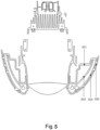
- Fig. 4 and Fig. 5 are respectively longitudinal and transverse sectional structural drawings of the array light curtain vehicle lamp
- Fig. 6 is a structural drawing of the array light curtain vehicle lamp in assembled form.
- the array light curtain vehicle lamp comprises: a base support 301, an LED assembly 302, a built-in light curtain lens 303, a built-in optimizing lens 304 and an outer trim ring 305.
- the base support 301 is mounted on a vehicle body structure.
- the LED assembly 302 is mounted on the base support 301, and the LED assembly 302 comprises a circuit board 321 and an LED light source 322.
- the built-in light curtain lens 303 is mounted in front of the base support 301, and the built-in light curtain lens 303 converts light emitted by the LED light source 302 to uniform horizontal light in the form of a light curtain.
- the built-in optimizing lens 304 is mounted in front of the built-in light curtain lens 303, and an optical optimization structure is formed on the built-in optimizing lens 304; the optical optimization structure optimizes the uniformity of light and forms an optical design.
- the outer trim ring 305 is mounted in front of the built-in optimizing lens 304, and an optical shielding structure is provided on the outer trim ring 305; the optical shielding structure blocks a portion of light to enhance the optical design. In the embodiment shown in Fig.
- the array light curtain vehicle lamp is arranged around a headlamp, with the base support 301, the built-in light curtain lens 303, the built-in optimizing lens 304 and the outer trim ring 305 being assembled in a sequentially nested manner; the base support 301, the built-in light curtain lens 303, the built-in optimizing lens 304 and the outer trim ring 305 all have a middle opening and two arc-shaped wings extending from the middle opening to two sides.
- the styling dimensions of the base support 301, the built-in light curtain lens 303, the built-in optimizing lens 304 and the outer trim ring 305 are all matched to each other, and for this reason the base support 301, the built-in light curtain lens 303, the built-in optimizing lens 304 and the outer trim ring 305 are able to be assembled by being stacked in sequence, one in front of another.
- the positions of the middle openings of the base support 301, the built-in light curtain lens 303, the built-in optimizing lens 304 and the outer trim ring 305 correspond to the position of the headlamp, such that after fitting, the array light curtain vehicle lamp can surround the headlamp.
- the LED assembly 302 is mounted at the top of the base support 301, and multiple LED light sources 322 are arranged on the circuit board 321.
- the multiple LED light sources 322 produce vertical light rays shining downward. In the embodiment shown, the light rays produced by the multiple LED light sources 322 shine vertically downward to an inner side of the built-in light curtain lens 303.
- the main function of the built-in light curtain lens 303 is to change the direction of light and homogenize the light rays, to obtain a light curtain effect.
- an optical pattern is formed on the inner side of the built-in light curtain lens 303, and the optical pattern converts vertical light rays to horizontal light rays.
- the optical pattern 331 formed on the inner side of the built-in light curtain lens 303 is uniformly distributed horizontal stripes, distributed on the built-in light curtain lens at inner sides of the two arc-shaped wings; the optical pattern 331 converts vertical light rays to uniformly distributed horizontal light rays, presenting a light curtain form.
- the main function of the built-in optimizing lens 304 is to further optimize the uniformity of light and form an optical design.
- the optical optimization structure on the built-in optimizing lens 304 comprises an arc-shaped light-transmitting plate 341 and light-transmitting protrusions 342.
- the arc-shaped light-transmitting plate 341 optimizes the uniformity of light; the light-transmitting protrusions 342 form the optical design.
- the arc-shaped light-transmitting plate 341 of the built-in optimizing lens 304 forms two arc-shaped wings, and the light-transmitting protrusions 342 are formed on the arc-shaped light-transmitting plate 341.
- the quantity, shapes, sizes and positions of the light-transmitting protrusions 342 are determined according to the required optical design.
- the required optical design is point-array light dots arranged in an array, so light-transmitting protrusions 342 arranged in an array are formed on the arc-shaped light-transmitting plate 341. Due to the arc-shaped structure of the arc-shaped light-transmitting plate 341, the light-transmitting protrusions 342 arranged on the arc-shaped light-transmitting plate 341 are distributed along an arc-shaped surface in space.
- the sizes, shapes and positions of the light-transmitting protrusions 342 arranged on the arc-shaped light-transmitting plate 341 are adjusted slightly to obtain the required optical design.
- the outer trim ring 305 is arranged in front of the built-in optimizing lens 304, and the main function of the outer trim ring 305 is to block a portion of light by means of the optical shielding structure, to enhance the display effect of the optical design.
- the shielding structure of the outer trim ring 305 is an arc-shaped plate 351 with light-transmitting holes 352.
- the arc-shaped plate 351 does not itself transmit light; the arc-shaped plate 351 forms two arc-shaped wings of the outer trim ring 305, and the light-transmitting holes 352 are matched to the light-transmitting protrusions 342 on the built-in optimizing lens 304.
- the non-light-transmitting arc-shaped plate 351 and the light-transmitting holes 352 cooperate with the light-transmitting protrusions 342 to jointly enhance the optical design.
- the quantity, shapes, sizes and positions of the light-transmitting holes 352 on the arc-shaped plate 351 are in one-to-one correspondence with those of the light-transmitting protrusions 342 on the built-in optimizing lens 304. Because only the light-transmitting holes 352 transmit light and the arc-shaped plate 351 is not light-transmitting, the optical shielding structure is better able to highlight the optical design formed by the light-transmitting protrusions 342, e.g. the display effect of point-array light dots arranged in an array that is formed in the embodiment shown.
- the array light curtain vehicle lamp of the present invention is formed of multiple components stacked in sequence one in front of another, so assembly and disassembly are convenient.
- the direction of light rays is changed and light rays are homogenized by means of two sets of lenses, so a light curtain effect is achieved using a compact structure.
- the optical design is achieved by means of the light-transmitting protrusions and the optical shielding structure, point-array optical display and design effects can be achieved flexibly according to requirements.
Landscapes
- Engineering & Computer Science (AREA)
- General Engineering & Computer Science (AREA)
- Physics & Mathematics (AREA)
- Microelectronics & Electronic Packaging (AREA)
- Optics & Photonics (AREA)
- Non-Portable Lighting Devices Or Systems Thereof (AREA)
- Lighting Device Outwards From Vehicle And Optical Signal (AREA)
Abstract
Description
- The present invention relates to the field of motor vehicle manufacture, in particular to a motor vehicle lighting assembly.
- The composition of the headlamp of a motor vehicle generally includes a high beam lamp, a low beam lamp, a turn signal lamp, a daytime running lamp, a corner lamp and a position lamp. Of these, the high beam lamp, low beam lamp, turn signal lamp and corner lamp are functional lamps, mainly for road surface illumination, turning and auxiliary turning, etc. The daytime running lamp and position lamp are an ornamental lamp and an indicating lamp. Functional lamps such as the high beam lamp, low beam lamp, turn signal lamp and corner lamp are switched on when they need to be used, and ordinarily remain switched off. Ornamental lamps and indicating lamps such as the daytime running lamp and position lamp will all be switched on when the vehicle is started, and are very identifiable and ornamental. Daytime running lamps and position lamps have gradually become an important component part of the design of a vehicle's appearance, and are playing an ever more prominent role in brand promotion and model identification, so are receiving a lot of attention from vehicle manufacturers everywhere.
- At present, LEDs are usually used as light sources for ornamental lamps and indicating lamps. The light effect is mainly achieved in the following two ways:
The first way is a solution in which an LED light source cooperates with a reflector.Figs. 1a and 1b show schematic drawings of a structure used in the prior art in which an LED light source cooperates with a reflector, whereinFig. 1b is a sectional drawing ofFig. 1a in direction A-A. As shown inFigs. 1a and 1b , in this solution, anLED assembly 101 is mounted at the top. TheLED assembly 101 consists of a circuit board (PCB) and an LED light source mounted on the PCB. A reflectingbowl 102 is arranged at a rear part of a lamp body. Light rays emitted by the LED light source are reflected by the reflectingbowl 102 straight ahead, i.e. ahead of the vehicle lamp. If it is desired to achieve an array or point array optical effect, it will be necessary to arrange an LED light source in the form of an array inside the light body, and carry out precise design and processing of the shape, dimensions and position of the reflecting bowl, to obtain a display effect of the reflected array light source. This solution requires a large space to arrange the LED array and the reflecting bowl, with the result that the overall volume of the lamp body is large, making cost control and space utilization difficult. Furthermore, the optical effect formed directly by reflection by the reflection bowl is unstable, and assembly errors are difficult to avoid during processing and installation of the reflecting bowl; consequently, the final actual optical effect is often different from the design effect. - The second way is a solution in which an LED light source cooperates with a light guide.
Figs. 2a and 2b show schematic drawings of a structure used in the prior art in which an LED light source cooperates with a light guide, whereinFig. 2b is a sectional drawing ofFig. 2a in direction A-A. As shown inFigs. 2a and 2b , in this solution, an LED light source is arranged at one end of alight guide 201, thelight guide 201 being fixed at the required position on a lamp body by means of light guide supports 202, 203. When the LED light source lights up, light rays are transmitted through the light guide, and all of the positions where the light guide is located will emit light, thereby achieving a strip-like optical effect. The light guide has a good flexibility characteristic, and can be designed to have various line shapes such as arc shapes, straight lines and polylines; moreover, the light guide will homogenize the light rays, so that the optical effect displayed is more uniform. However, there are also very significant drawbacks associated with using the light guide solution. Firstly, the cost is high; to install a light guide, it is first necessary to install light guide supports, and the material costs and work costs associated with this are both high, so light guides can only be used in high-end models. Secondly, light guides are mainly used for linetype optical effects, being unable to achieve point array optical effects, so have considerable limitations with regard to optical styling. - In summary, ornamental lamps and indicating lamps with LEDs as light sources in the prior art have certain limitations with regard to implementation cost and optical styling flexibility, so are unable to fully meet market demands.
- The aim of the present invention is to propose a structurally simple array light curtain vehicle lamp with a low implementation cost.
- According to an embodiment of the present invention, an array light curtain vehicle lamp is proposed, comprising: a base support an LED assembly, a built-in light curtain lens, a built-in optimizing lens and an outer trim ring. The base support is mounted on a vehicle body structure. The LED assembly is mounted on the base support, and the LED assembly comprises a circuit board and an LED light source. The built-in light curtain lens is mounted in front of the base support, the built-in light curtain lens converting light emitted by the LED light source to uniform horizontal light in the form of a light curtain. The built-in optimizing lens is mounted in front of the built-in light curtain lens, with an optical optimization structure formed on the built-in optimizing lens, the optical optimization structure optimizing the uniformity of light and forming an optical design. The outer trim ring is mounted in front of the built-in optimizing lens, with an optical shielding structure provided on the outer trim ring, the optical shielding structure blocking a portion of light to enhance the optical design.
- In one embodiment, the array light curtain vehicle lamp is arranged around a headlamp, with the base support, the built-in light curtain lens, the built-in optimizing lens and the outer trim ring being assembled in a sequentially nested manner; the base support, the built-in light curtain lens, the built-in optimizing lens and the outer trim ring all have a middle opening and two arc-shaped wings extending from the middle opening to two sides, and the position of the middle opening corresponds to the position of the headlamp.
- In one embodiment, the LED assembly is mounted at the top of the base support, and multiple LED light sources are arranged on the circuit board, the multiple LED light sources producing vertical light rays shining downward.
- In one embodiment, an optical pattern is formed on an inner side of the built-in light curtain lens, the optical pattern converting vertical light rays to horizontal light rays.
- In one embodiment, the optical pattern is uniformly distributed horizontal stripes, distributed on the built-in light curtain lens at inner sides of the two arc-shaped wings, and the optical pattern converts vertical light rays to uniformly distributed horizontal light rays, presenting a light curtain form.
- In one embodiment, the optical optimization structure on the built-in optimizing lens comprises an arc-shaped light-transmitting plate and a light-transmitting protrusion; the arc-shaped light-transmitting plate optimizes the uniformity of light, and the light-transmitting protrusion forms the optical design.
- In one embodiment, the arc-shaped light-transmitting plate of the built-in optimizing lens forms two arc-shaped wings, and the light-transmitting protrusion is formed on the arc-shaped light-transmitting plate; the quantity, shape, size and position of the light-transmitting protrusion are determined according to the required optical design.
- In one embodiment, the shielding structure of the outer trim ring is an arc-shaped plate with a light-transmitting hole, the arc-shaped plate does not transmit light, the arc-shaped plate forms two arc-shaped wings, the light-transmitting hole is matched to the light-transmitting protrusion on the built-in optimizing lens, and the arc-shaped plate and light-transmitting hole enhance the optical design.
- In one embodiment, the quantity, shape, size and position of the light-transmitting hole are in one-to-one correspondence with those of the light-transmitting protrusion on the built-in optimizing lens.
- The array light curtain vehicle lamp of the present invention is formed of multiple components stacked in sequence one in front of another, so assembly and disassembly are convenient. The direction of light rays is changed and light rays are homogenized by means of two sets of lenses, so a light curtain effect is achieved using a compact structure. As the optical design is achieved by means of the light-transmitting protrusion and the optical shielding structure, point-array optical display and design effects can be achieved flexibly according to requirements.
- The above and other features, properties and advantages of the present invention will become clearer through the following description with reference to the drawings and embodiments; in the drawings, identical reference labels always indicate identical features, wherein:
-
Figs. 1a and 1b show schematic drawings of a structure used in the prior art in which an LED light source cooperates with a reflector, whereinFig. 1b is a sectional drawing ofFig. 1a in direction A-A. -
Figs. 2a and 2b show schematic drawings of a structure used in the prior art in which an LED light source cooperates with a light guide, whereinFig. 2b is a sectional drawing ofFig. 2a in direction A-A. -
Fig. 3 shows an exploded structural drawing of an array light curtain vehicle lamp according to an embodiment of the present invention. -
Fig. 4 shows a longitudinal sectional structural drawing of an array light curtain vehicle lamp according to an embodiment of the present invention. -
Fig. 5 shows a transverse sectional structural drawing of an array light curtain vehicle lamp according to an embodiment of the present invention. -
Fig. 6 shows a structural drawing of an array light curtain vehicle lamp according to an embodiment of the present invention in assembled form. - Referring to
Figs. 3 - 6, Figs. 3 - 6 show a structural drawing of an array light curtain vehicle lamp according to an embodiment of the present invention.Fig. 3 shows an exploded structural drawing of the array light curtain vehicle lamp,Fig. 4 andFig. 5 are respectively longitudinal and transverse sectional structural drawings of the array light curtain vehicle lamp, andFig. 6 is a structural drawing of the array light curtain vehicle lamp in assembled form. - As shown in the figures, the array light curtain vehicle lamp comprises: a
base support 301, anLED assembly 302, a built-inlight curtain lens 303, a built-in optimizinglens 304 and anouter trim ring 305. Thebase support 301 is mounted on a vehicle body structure. TheLED assembly 302 is mounted on thebase support 301, and theLED assembly 302 comprises acircuit board 321 and anLED light source 322. The built-inlight curtain lens 303 is mounted in front of thebase support 301, and the built-inlight curtain lens 303 converts light emitted by the LEDlight source 302 to uniform horizontal light in the form of a light curtain. The built-in optimizinglens 304 is mounted in front of the built-inlight curtain lens 303, and an optical optimization structure is formed on the built-in optimizinglens 304; the optical optimization structure optimizes the uniformity of light and forms an optical design. Theouter trim ring 305 is mounted in front of the built-in optimizinglens 304, and an optical shielding structure is provided on theouter trim ring 305; the optical shielding structure blocks a portion of light to enhance the optical design. In the embodiment shown inFig. 3 , the array light curtain vehicle lamp is arranged around a headlamp, with thebase support 301, the built-inlight curtain lens 303, the built-in optimizinglens 304 and theouter trim ring 305 being assembled in a sequentially nested manner; thebase support 301, the built-inlight curtain lens 303, the built-in optimizinglens 304 and theouter trim ring 305 all have a middle opening and two arc-shaped wings extending from the middle opening to two sides. The styling dimensions of thebase support 301, the built-inlight curtain lens 303, the built-in optimizinglens 304 and theouter trim ring 305 are all matched to each other, and for this reason thebase support 301, the built-inlight curtain lens 303, the built-in optimizinglens 304 and theouter trim ring 305 are able to be assembled by being stacked in sequence, one in front of another. The positions of the middle openings of thebase support 301, the built-inlight curtain lens 303, the built-in optimizinglens 304 and theouter trim ring 305 correspond to the position of the headlamp, such that after fitting, the array light curtain vehicle lamp can surround the headlamp. - Referring to
Figs. 3 and4 , theLED assembly 302 is mounted at the top of thebase support 301, and multiple LEDlight sources 322 are arranged on thecircuit board 321. The multiple LEDlight sources 322 produce vertical light rays shining downward. In the embodiment shown, the light rays produced by the multiple LEDlight sources 322 shine vertically downward to an inner side of the built-inlight curtain lens 303. - The main function of the built-in
light curtain lens 303 is to change the direction of light and homogenize the light rays, to obtain a light curtain effect. In one embodiment, an optical pattern is formed on the inner side of the built-inlight curtain lens 303, and the optical pattern converts vertical light rays to horizontal light rays. In the embodiment shown, theoptical pattern 331 formed on the inner side of the built-inlight curtain lens 303 is uniformly distributed horizontal stripes, distributed on the built-in light curtain lens at inner sides of the two arc-shaped wings; theoptical pattern 331 converts vertical light rays to uniformly distributed horizontal light rays, presenting a light curtain form. - The main function of the built-in optimizing
lens 304 is to further optimize the uniformity of light and form an optical design. In one embodiment, the optical optimization structure on the built-in optimizinglens 304 comprises an arc-shaped light-transmittingplate 341 and light-transmittingprotrusions 342. The arc-shaped light-transmittingplate 341 optimizes the uniformity of light; the light-transmittingprotrusions 342 form the optical design. In the embodiment shown, the arc-shaped light-transmittingplate 341 of the built-in optimizinglens 304 forms two arc-shaped wings, and the light-transmittingprotrusions 342 are formed on the arc-shaped light-transmittingplate 341. The quantity, shapes, sizes and positions of the light-transmittingprotrusions 342 are determined according to the required optical design. In the embodiment shown, the required optical design is point-array light dots arranged in an array, so light-transmittingprotrusions 342 arranged in an array are formed on the arc-shaped light-transmittingplate 341. Due to the arc-shaped structure of the arc-shaped light-transmittingplate 341, the light-transmittingprotrusions 342 arranged on the arc-shaped light-transmittingplate 341 are distributed along an arc-shaped surface in space. In order to obtain, from the front, an optical effect of point-array light dots arranged in an array, the sizes, shapes and positions of the light-transmittingprotrusions 342 arranged on the arc-shaped light-transmittingplate 341 are adjusted slightly to obtain the required optical design. - The
outer trim ring 305 is arranged in front of the built-in optimizinglens 304, and the main function of theouter trim ring 305 is to block a portion of light by means of the optical shielding structure, to enhance the display effect of the optical design. In the embodiment shown, the shielding structure of theouter trim ring 305 is an arc-shapedplate 351 with light-transmittingholes 352. The arc-shapedplate 351 does not itself transmit light; the arc-shapedplate 351 forms two arc-shaped wings of theouter trim ring 305, and the light-transmittingholes 352 are matched to the light-transmittingprotrusions 342 on the built-in optimizinglens 304. The non-light-transmitting arc-shapedplate 351 and the light-transmittingholes 352 cooperate with the light-transmittingprotrusions 342 to jointly enhance the optical design. In the embodiment shown, the quantity, shapes, sizes and positions of the light-transmittingholes 352 on the arc-shapedplate 351 are in one-to-one correspondence with those of the light-transmittingprotrusions 342 on the built-in optimizinglens 304. Because only the light-transmittingholes 352 transmit light and the arc-shapedplate 351 is not light-transmitting, the optical shielding structure is better able to highlight the optical design formed by the light-transmittingprotrusions 342, e.g. the display effect of point-array light dots arranged in an array that is formed in the embodiment shown. - The array light curtain vehicle lamp of the present invention is formed of multiple components stacked in sequence one in front of another, so assembly and disassembly are convenient. The direction of light rays is changed and light rays are homogenized by means of two sets of lenses, so a light curtain effect is achieved using a compact structure. As the optical design is achieved by means of the light-transmitting protrusions and the optical shielding structure, point-array optical display and design effects can be achieved flexibly according to requirements.
- The above embodiment is provided for those skilled in the art to implement or use the present invention, but those skilled in the art could make various amendments or changes to the above embodiment without departing from the inventive concept of the present invention, so the scope of protection of the present invention is not limited by the above embodiment, but should be the maximum scope conforming to the innovative features mentioned in the claims.
Claims (9)
- An array light curtain vehicle lamp, characterized by comprising:a base support, mounted on a vehicle body structure;an LED assembly, the LED assembly being mounted on the base support, and the LED assembly comprising a circuit board and an LED light source;a built-in light curtain lens, mounted in front of the base support, the built-in light curtain lens converting light emitted by the LED light source to uniform horizontal light in the form of a light curtain;a built-in optimizing lens, mounted in front of the built-in light curtain lens, with an optical optimization structure formed on the built-in optimizing lens, the optical optimization structure optimizing the uniformity of light and forming an optical design;an outer trim ring, mounted in front of the built-in optimizing lens, with an optical shielding structure provided on the outer trim ring, the optical shielding structure blocking a portion of light to enhance the optical design.
- The array light curtain vehicle lamp as claimed in claim 1, characterized in that the array light curtain vehicle lamp is arranged around a headlamp, with the base support, the built-in light curtain lens, the built-in optimizing lens and the outer trim ring being assembled in a sequentially nested manner; the base support, the built-in light curtain lens, the built-in optimizing lens and the outer trim ring all have a middle opening and two arc-shaped wings extending from the middle opening to two sides, and the position of the middle opening corresponds to the position of the headlamp.
- The array light curtain vehicle lamp as claimed in claim 2, characterized in that the LED assembly is mounted at the top of the base support, and multiple LED light sources are arranged on the circuit board, the multiple LED light sources producing vertical light rays shining downward.
- The array light curtain vehicle lamp as claimed in claim 3, characterized in that an optical pattern is formed on an inner side of the built-in light curtain lens, the optical pattern converting vertical light rays to horizontal light rays.
- The array light curtain vehicle lamp as claimed in claim 4, characterized in that the optical pattern is uniformly distributed horizontal stripes, distributed on the built-in light curtain lens at inner sides of the two arc-shaped wings, and the optical pattern converts vertical light rays to uniformly distributed horizontal light rays, presenting a light curtain form.
- The array light curtain vehicle lamp as claimed in claim 2, characterized in that the optical optimization structure on the built-in optimizing lens comprises an arc-shaped light-transmitting plate and a light-transmitting protrusion; the arc-shaped light-transmitting plate optimizes the uniformity of light, and the light-transmitting protrusion forms the optical design.
- The array light curtain vehicle lamp as claimed in claim 6, characterized in that the arc-shaped light-transmitting plate of the built-in optimizing lens forms two arc-shaped wings, and the light-transmitting protrusion is formed on the arc-shaped light-transmitting plate; the quantity, shape, size and position of the light-transmitting protrusion are determined according to the required optical design.
- The array light curtain vehicle lamp as claimed in claim 7, characterized in that the shielding structure of the outer trim ring is an arc-shaped plate with a light-transmitting hole, the arc-shaped plate does not transmit light, the arc-shaped plate forms two arc-shaped wings, the light-transmitting hole is matched to the light-transmitting protrusion on the built-in optimizing lens, and the arc-shaped plate and light-transmitting hole enhance the optical design.
- The array light curtain vehicle lamp as claimed in claim 8, characterized in that the quantity, shape, size and position of the light-transmitting hole are in one-to-one correspondence with those of the light-transmitting protrusion on the built-in optimizing lens.
Applications Claiming Priority (2)
| Application Number | Priority Date | Filing Date | Title |
|---|---|---|---|
| CN202020144467.4U CN211083952U (en) | 2020-01-22 | 2020-01-22 | Array light curtain type car lamp |
| PCT/CN2021/081486 WO2021148055A1 (en) | 2020-01-22 | 2021-03-18 | Array light curtain vehicle lamp |
Publications (2)
| Publication Number | Publication Date |
|---|---|
| EP4151903A1 true EP4151903A1 (en) | 2023-03-22 |
| EP4151903A4 EP4151903A4 (en) | 2024-05-15 |
Family
ID=71630721
Family Applications (1)
| Application Number | Title | Priority Date | Filing Date |
|---|---|---|---|
| EP21744511.3A Withdrawn EP4151903A4 (en) | 2020-01-22 | 2021-03-18 | Array light curtain vehicle lamp |
Country Status (3)
| Country | Link |
|---|---|
| EP (1) | EP4151903A4 (en) |
| CN (1) | CN211083952U (en) |
| WO (1) | WO2021148055A1 (en) |
Families Citing this family (2)
| Publication number | Priority date | Publication date | Assignee | Title |
|---|---|---|---|---|
| CN211083952U (en) * | 2020-01-22 | 2020-07-24 | 上汽大众汽车有限公司 | Array light curtain type car lamp |
| CN115789562B (en) * | 2022-11-30 | 2025-11-14 | 马瑞利汽车照明系统(佛山)有限公司 | A headlight with auxiliary signal light |
Family Cites Families (8)
| Publication number | Priority date | Publication date | Assignee | Title |
|---|---|---|---|---|
| US20160167576A1 (en) * | 2014-12-12 | 2016-06-16 | Kuo-Jen Lee | Automobile warning structure |
| CN204629366U (en) * | 2015-04-09 | 2015-09-09 | 重庆秦川工贸有限公司 | The lens of the even bright dipping of a kind of high-mount brake lamp |
| CN206617870U (en) * | 2017-03-30 | 2017-11-07 | 上海小糸车灯有限公司 | A kind of Vehicle lamp structure with efficient and various shapes light curtain effect |
| CN109827145A (en) * | 2018-07-10 | 2019-05-31 | 华域视觉科技(上海)有限公司 | A kind of rear combination signal lamp and its anti-channeling photo structure of anti-channeling light |
| CN208817379U (en) * | 2018-11-23 | 2019-05-03 | 华域视觉科技(上海)有限公司 | Color matching automobile long-and-short distant light |
| CN110056793A (en) * | 2019-03-31 | 2019-07-26 | 湖南凯星电子科技有限公司 | One kind shines uniform module lamp box back light unit and light emitting module |
| CN209991402U (en) * | 2019-05-24 | 2020-01-24 | 华域视觉科技(上海)有限公司 | Front signal lamp with uniform light curtain effect |
| CN211083952U (en) * | 2020-01-22 | 2020-07-24 | 上汽大众汽车有限公司 | Array light curtain type car lamp |
-
2020
- 2020-01-22 CN CN202020144467.4U patent/CN211083952U/en not_active Expired - Fee Related
-
2021
- 2021-03-18 EP EP21744511.3A patent/EP4151903A4/en not_active Withdrawn
- 2021-03-18 WO PCT/CN2021/081486 patent/WO2021148055A1/en not_active Ceased
Also Published As
| Publication number | Publication date |
|---|---|
| CN211083952U (en) | 2020-07-24 |
| WO2021148055A1 (en) | 2021-07-29 |
| EP4151903A4 (en) | 2024-05-15 |
Similar Documents
| Publication | Publication Date | Title |
|---|---|---|
| US9435506B2 (en) | Lighting device in a motor vehicle having a plate-shaped light conductor and a rod-shaped light conductor | |
| CN210485572U (en) | Run through lamp and vehicle before car | |
| US20040145910A1 (en) | Lighting assembly | |
| EP4151903A1 (en) | Array light curtain vehicle lamp | |
| JP7176961B2 (en) | rear combination lamp | |
| US20090207610A1 (en) | Combination rear lighting system | |
| CN107435882B (en) | lighting device | |
| US6871990B2 (en) | Vehicle lamp with visor | |
| US11512832B2 (en) | Light bulb and crystal lamp | |
| US20040218399A1 (en) | Vehicle lighting device | |
| CN210740290U (en) | a combined signal light | |
| CN220249736U (en) | Narrow-opening optical system and LED module thereof | |
| CN220623774U (en) | Dual-functional lighting system and use its automobile-used signal lamp | |
| JP4631840B2 (en) | Vehicle lighting | |
| CN208312244U (en) | LED automobile tail lamp | |
| CN208222400U (en) | A kind of light guide by Two-way side entering light realizes the rear combination lamp of uniformly light-emitting | |
| CN216521420U (en) | Position lamp and car behind light guide light curtain combination | |
| CN206072937U (en) | Vehicular illumination system lamp device | |
| CN214094302U (en) | High beam car light optical element, vehicle high beam lighting unit, car light and vehicle | |
| CN108626691B (en) | Rear combined lamp capable of realizing uniform light emission through light guide of two-way side light | |
| CN212618072U (en) | Automobile optical signal device | |
| CN210462867U (en) | Multi-piece screen micro-pattern automobile tail lamp | |
| CN108571701A (en) | A kind of car light optical waveguide module | |
| CN220958051U (en) | Front fog lamp with split effect | |
| CN219198970U (en) | Novel compact high beam and low beam integrated module |
Legal Events
| Date | Code | Title | Description |
|---|---|---|---|
| STAA | Information on the status of an ep patent application or granted ep patent |
Free format text: STATUS: THE INTERNATIONAL PUBLICATION HAS BEEN MADE |
|
| PUAI | Public reference made under article 153(3) epc to a published international application that has entered the european phase |
Free format text: ORIGINAL CODE: 0009012 |
|
| STAA | Information on the status of an ep patent application or granted ep patent |
Free format text: STATUS: REQUEST FOR EXAMINATION WAS MADE |
|
| 17P | Request for examination filed |
Effective date: 20220822 |
|
| AK | Designated contracting states |
Kind code of ref document: A1 Designated state(s): AL AT BE BG CH CY CZ DE DK EE ES FI FR GB GR HR HU IE IS IT LI LT LU LV MC MK MT NL NO PL PT RO RS SE SI SK SM TR |
|
| XX | Miscellaneous (additional remarks) |
Free format text: A REQUEST FOR RESTORATION OF THE RIGHT OF PRIORITY UNDER RULE 49TER.2 PCT IS PENDING BEFORE THE EPO AS DESIGNATED OFFICE. |
|
| DAV | Request for validation of the european patent (deleted) | ||
| DAX | Request for extension of the european patent (deleted) | ||
| A4 | Supplementary search report drawn up and despatched |
Effective date: 20240416 |
|
| RIC1 | Information provided on ipc code assigned before grant |
Ipc: F21W 103/10 20180101ALI20240410BHEP Ipc: F21W 103/55 20180101ALI20240410BHEP Ipc: F21S 43/27 20180101ALI20240410BHEP Ipc: F21S 43/245 20180101ALI20240410BHEP Ipc: F21S 43/241 20180101ALI20240410BHEP Ipc: F21S 43/239 20180101ALI20240410BHEP Ipc: F21V 8/00 20060101ALI20240410BHEP Ipc: F21S 43/50 20180101ALI20240410BHEP Ipc: F21S 43/20 20180101ALI20240410BHEP Ipc: F21S 43/14 20180101AFI20240410BHEP |
|
| STAA | Information on the status of an ep patent application or granted ep patent |
Free format text: STATUS: THE APPLICATION IS DEEMED TO BE WITHDRAWN |
|
| 18D | Application deemed to be withdrawn |
Effective date: 20241107 |