EP4151844A1 - Turbomachine with e-machine housing thermal fluid retainer member - Google Patents
Turbomachine with e-machine housing thermal fluid retainer member Download PDFInfo
- Publication number
- EP4151844A1 EP4151844A1 EP22181597.0A EP22181597A EP4151844A1 EP 4151844 A1 EP4151844 A1 EP 4151844A1 EP 22181597 A EP22181597 A EP 22181597A EP 4151844 A1 EP4151844 A1 EP 4151844A1
- Authority
- EP
- European Patent Office
- Prior art keywords
- housing
- stator
- turbomachine
- machine
- machine housing
- Prior art date
- Legal status (The legal status is an assumption and is not a legal conclusion. Google has not performed a legal analysis and makes no representation as to the accuracy of the status listed.)
- Granted
Links
Images




Classifications
-
- F—MECHANICAL ENGINEERING; LIGHTING; HEATING; WEAPONS; BLASTING
- F04—POSITIVE - DISPLACEMENT MACHINES FOR LIQUIDS; PUMPS FOR LIQUIDS OR ELASTIC FLUIDS
- F04D—NON-POSITIVE-DISPLACEMENT PUMPS
- F04D29/00—Details, component parts, or accessories
- F04D29/58—Cooling; Heating; Diminishing heat transfer
- F04D29/5806—Cooling the drive system
-
- F—MECHANICAL ENGINEERING; LIGHTING; HEATING; WEAPONS; BLASTING
- F01—MACHINES OR ENGINES IN GENERAL; ENGINE PLANTS IN GENERAL; STEAM ENGINES
- F01D—NON-POSITIVE DISPLACEMENT MACHINES OR ENGINES, e.g. STEAM TURBINES
- F01D15/00—Adaptations of machines or engines for special use; Combinations of engines with devices driven thereby
- F01D15/10—Adaptations for driving, or combinations with, electric generators
-
- F—MECHANICAL ENGINEERING; LIGHTING; HEATING; WEAPONS; BLASTING
- F01—MACHINES OR ENGINES IN GENERAL; ENGINE PLANTS IN GENERAL; STEAM ENGINES
- F01D—NON-POSITIVE DISPLACEMENT MACHINES OR ENGINES, e.g. STEAM TURBINES
- F01D25/00—Component parts, details, or accessories, not provided for in, or of interest apart from, other groups
- F01D25/08—Cooling; Heating; Heat-insulation
- F01D25/14—Casings modified therefor
-
- F—MECHANICAL ENGINEERING; LIGHTING; HEATING; WEAPONS; BLASTING
- F01—MACHINES OR ENGINES IN GENERAL; ENGINE PLANTS IN GENERAL; STEAM ENGINES
- F01D—NON-POSITIVE DISPLACEMENT MACHINES OR ENGINES, e.g. STEAM TURBINES
- F01D25/00—Component parts, details, or accessories, not provided for in, or of interest apart from, other groups
- F01D25/24—Casings; Casing parts, e.g. diaphragms, casing fastenings
-
- F—MECHANICAL ENGINEERING; LIGHTING; HEATING; WEAPONS; BLASTING
- F01—MACHINES OR ENGINES IN GENERAL; ENGINE PLANTS IN GENERAL; STEAM ENGINES
- F01D—NON-POSITIVE DISPLACEMENT MACHINES OR ENGINES, e.g. STEAM TURBINES
- F01D25/00—Component parts, details, or accessories, not provided for in, or of interest apart from, other groups
- F01D25/24—Casings; Casing parts, e.g. diaphragms, casing fastenings
- F01D25/243—Flange connections; Bolting arrangements
-
- F—MECHANICAL ENGINEERING; LIGHTING; HEATING; WEAPONS; BLASTING
- F01—MACHINES OR ENGINES IN GENERAL; ENGINE PLANTS IN GENERAL; STEAM ENGINES
- F01D—NON-POSITIVE DISPLACEMENT MACHINES OR ENGINES, e.g. STEAM TURBINES
- F01D25/00—Component parts, details, or accessories, not provided for in, or of interest apart from, other groups
- F01D25/24—Casings; Casing parts, e.g. diaphragms, casing fastenings
- F01D25/246—Fastening of diaphragms or stator-rings
-
- F—MECHANICAL ENGINEERING; LIGHTING; HEATING; WEAPONS; BLASTING
- F02—COMBUSTION ENGINES; HOT-GAS OR COMBUSTION-PRODUCT ENGINE PLANTS
- F02C—GAS-TURBINE PLANTS; AIR INTAKES FOR JET-PROPULSION PLANTS; CONTROLLING FUEL SUPPLY IN AIR-BREATHING JET-PROPULSION PLANTS
- F02C6/00—Plural gas-turbine plants; Combinations of gas-turbine plants with other apparatus; Adaptations of gas-turbine plants for special use
- F02C6/04—Gas-turbine plants providing heated or pressurised working fluid for other apparatus, e.g. without mechanical power output
- F02C6/10—Gas-turbine plants providing heated or pressurised working fluid for other apparatus, e.g. without mechanical power output supplying working fluid to a user, e.g. a chemical process, which returns working fluid to a turbine of the plant
- F02C6/12—Turbochargers, i.e. plants for augmenting mechanical power output of internal-combustion piston engines by increase of charge pressure
-
- F—MECHANICAL ENGINEERING; LIGHTING; HEATING; WEAPONS; BLASTING
- F04—POSITIVE - DISPLACEMENT MACHINES FOR LIQUIDS; PUMPS FOR LIQUIDS OR ELASTIC FLUIDS
- F04D—NON-POSITIVE-DISPLACEMENT PUMPS
- F04D25/00—Pumping installations or systems
- F04D25/02—Units comprising pumps and their driving means
- F04D25/04—Units comprising pumps and their driving means the pump being fluid-driven
-
- F—MECHANICAL ENGINEERING; LIGHTING; HEATING; WEAPONS; BLASTING
- F04—POSITIVE - DISPLACEMENT MACHINES FOR LIQUIDS; PUMPS FOR LIQUIDS OR ELASTIC FLUIDS
- F04D—NON-POSITIVE-DISPLACEMENT PUMPS
- F04D25/00—Pumping installations or systems
- F04D25/02—Units comprising pumps and their driving means
- F04D25/06—Units comprising pumps and their driving means the pump being electrically driven
-
- H—ELECTRICITY
- H02—GENERATION; CONVERSION OR DISTRIBUTION OF ELECTRIC POWER
- H02K—DYNAMO-ELECTRIC MACHINES
- H02K7/00—Arrangements for handling mechanical energy structurally associated with dynamo-electric machines, e.g. structural association with mechanical driving motors or auxiliary dynamo-electric machines
- H02K7/18—Structural association of electric generators with mechanical driving motors, e.g. with turbines
- H02K7/1807—Rotary generators
- H02K7/1823—Rotary generators structurally associated with turbines or similar engines
-
- H—ELECTRICITY
- H02—GENERATION; CONVERSION OR DISTRIBUTION OF ELECTRIC POWER
- H02K—DYNAMO-ELECTRIC MACHINES
- H02K9/00—Arrangements for cooling or ventilating
- H02K9/22—Arrangements for cooling or ventilating by solid heat conducting material embedded in, or arranged in contact with, the stator or rotor, e.g. heat bridges
- H02K9/223—Heat bridges
-
- F—MECHANICAL ENGINEERING; LIGHTING; HEATING; WEAPONS; BLASTING
- F05—INDEXING SCHEMES RELATING TO ENGINES OR PUMPS IN VARIOUS SUBCLASSES OF CLASSES F01-F04
- F05D—INDEXING SCHEME FOR ASPECTS RELATING TO NON-POSITIVE-DISPLACEMENT MACHINES OR ENGINES, GAS-TURBINES OR JET-PROPULSION PLANTS
- F05D2220/00—Application
- F05D2220/40—Application in turbochargers
-
- F—MECHANICAL ENGINEERING; LIGHTING; HEATING; WEAPONS; BLASTING
- F05—INDEXING SCHEMES RELATING TO ENGINES OR PUMPS IN VARIOUS SUBCLASSES OF CLASSES F01-F04
- F05D—INDEXING SCHEME FOR ASPECTS RELATING TO NON-POSITIVE-DISPLACEMENT MACHINES OR ENGINES, GAS-TURBINES OR JET-PROPULSION PLANTS
- F05D2220/00—Application
- F05D2220/70—Application in combination with
- F05D2220/76—Application in combination with an electrical generator
-
- F—MECHANICAL ENGINEERING; LIGHTING; HEATING; WEAPONS; BLASTING
- F05—INDEXING SCHEMES RELATING TO ENGINES OR PUMPS IN VARIOUS SUBCLASSES OF CLASSES F01-F04
- F05D—INDEXING SCHEME FOR ASPECTS RELATING TO NON-POSITIVE-DISPLACEMENT MACHINES OR ENGINES, GAS-TURBINES OR JET-PROPULSION PLANTS
- F05D2260/00—Function
- F05D2260/20—Heat transfer, e.g. cooling
- F05D2260/221—Improvement of heat transfer
Definitions
- the e-machine may cause and/or contribute to increased temperatures during operation of these e-machine equipped turbomachines.
- Conventional cooling systems/features may be insufficient for some e-machines. Also, these cooling systems/features may decrease manufacturability and/or increase costs.
- the e-machine section 110 is shown in greater detail according to example embodiments.
- the section 110 extends axially between a first end 161 and a second end 162.
- the motor 122 may include a number of teeth 125 as well as windings 127 that extend axially and wrap about the respective ones of the teeth 125.
- the windings 127 may include first turns 129 proximate the first axial end 161 of the respective tooth 125 and second turns 131 proximate the second axial end 162.
Landscapes
- Engineering & Computer Science (AREA)
- Mechanical Engineering (AREA)
- General Engineering & Computer Science (AREA)
- Power Engineering (AREA)
- Chemical & Material Sciences (AREA)
- Physics & Mathematics (AREA)
- Thermal Sciences (AREA)
- Chemical Kinetics & Catalysis (AREA)
- General Chemical & Material Sciences (AREA)
- Combustion & Propulsion (AREA)
- Structures Of Non-Positive Displacement Pumps (AREA)
- Motor Or Generator Cooling System (AREA)
Abstract
Description
- The present disclosure generally relates to a turbomachine and, more particularly, relates to a turbomachine with an e-machine housing having a thermal fluid retainer member.
- Some turbomachines are provided with an e-machine. For example, some turbochargers, superchargers, and other compressor devices may include a compressor section that compresses a fluid via rotation of a rotating group within a housing, and these devices may also include an electric motor that drives (or assists in driving) rotation of the rotating group. Additionally, some devices may include an electric generator that converts rotational energy of the rotating group into electrical energy.
- However, challenges remain. Excessive temperatures can negatively affect operation and/or efficiency of these devices. The e-machine may cause and/or contribute to increased temperatures during operation of these e-machine equipped turbomachines. Conventional cooling systems/features may be insufficient for some e-machines. Also, these cooling systems/features may decrease manufacturability and/or increase costs.
- Thus, it is desirable to provide a turbomachine with an operably attached e-machine having improved cooling features. It is also desirable to provide a turbomachine that is also highly manufacturable and cost effective. Other desirable features and characteristics of the present disclosure will become apparent from the subsequent detailed description and the appended claims, taken in conjunction with the accompanying drawings and this background discussion.
- In one embodiment, a turbomachine is disclosed that includes a housing with an e-machine housing. Also, the turbomachine includes a rotating group supported for rotation within the housing. Moreover, the turbomachine includes an e-machine that is configured as at least one of an electric motor and an electric generator, that is operatively coupled to the rotating group, and that includes a stator that is housed within the e-machine housing. Furthermore, the turbomachine includes a thermal bridge member that extends between the stator and the e-machine housing to define a thermal path for heat to transfer from the stator to the e-machine housing. The e-machine housing includes a thermal bridge retainer member that defines an outer boundary of the thermal bridge member.
- In another embodiment, a method of manufacturing a turbomachine is disclosed that includes providing a housing that includes an e-machine housing and a retainer member. Also, the method includes supporting a rotating group for rotation within the housing. Furthermore, the method includes operatively coupling an e-machine to the rotating group. The e-machine is configured as at least one of an electric motor and an electric generator. Additionally, the method includes extending a thermal bridge member between a stator of the e-machine and the e-machine housing to define a thermal path for heat to transfer from the stator to the e-machine housing. Moreover, the method includes defining an outer boundary of the thermal bridge member with the retainer member.
- In an additional embodiment, an e-charging device is disclosed that includes a housing with a motor housing. The motor housing has an inner axial surface. The e-charging device further includes a rotating group supported for rotation within the housing. Moreover, the e-charging device includes a fluid compressor section that is cooperatively defined by the housing and the rotating group. Furthermore, the e-charging device includes an electric motor that is coupled to the rotating group for drivingly rotating the rotating group about an axis within the housing. The electric motor includes a stator that is housed within the motor housing. Also, the e-charging device includes a thermal bridge member that extends between the stator and the motor housing to define a thermal path for heat to transfer from the stator to the motor housing. Additionally, the motor housing including a thermal bridge retainer member that is cooperatively defined by the inner axial surface and a dam wall of an insert that overlies the inner axial surface. The dam wall defines an outer boundary of the thermal bridge member to retain the thermal bridge member in a position proximate the stator of the electric motor.
- The present disclosure will hereinafter be described in conjunction with the following drawing figures, wherein like numerals denote like elements, and wherein:
-
FIG. 1 is a schematic illustration of a turbomachine incorporated, for example, in a fuel cell system; -
FIG. 2 is a cross-sectional view of a motor section of the turbomachine according to example embodiments of the present disclosure; -
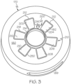
FIG. 3 is an isometric view of a motor housing and an insert that cooperatively define a thermal fluid retainer member according to example embodiments of the present disclosure; -
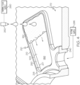
FIG. 4 is a detail view of the retainer member ofFIG. 3 and a thermal fluid shown schematically during application; -
FIG. 5 is a first side isometric view of the insert of the retainer member ofFIG. 3 ; and -
FIG. 6 is a second side isometric view of the insert of the retainer member ofFIG. 3 . - The following detailed description is merely exemplary in nature and is not intended to limit the present disclosure or the application and uses of the present disclosure. Furthermore, there is no intention to be bound by any theory presented in the preceding background or the following detailed description.
- Broadly, example embodiments disclosed herein include a turbomachine with an operably attached e-machine, such as an electric motor, that includes heat transfer features for maintaining operating temperatures within acceptable ranges. The turbomachine may include a so-called "thermal bridge member," such as thermal compound, thermal fluid, thermal paste, or other thermal interface for defining a thermal path for heat to transfer away from the turbomachine. Accordingly, the e-machine may provide highly efficient performance without dramatically increasing operating temperatures.
- In some embodiments, the turbomachine may include a thermal bridge retainer member. More specifically, the e-machine may be housed within an e-machine housing, and thermal fluid (e.g., a thermal paste) with a relatively high thermal conductivity may be included to provide a thermal conductive path for heat transfer out of the stator of the e-machine, into the housing, and away from the e-machine. This configuration may be provided in an air-cooled e-machine in some embodiments.
- The thermal fluid retainer member may be included for retaining the thermal fluid in a predetermined position relative to the stator of the e-machine. The retainer member may be disposed adjacent and proximate one or more axial end turns of the stator. The retainer member may define a receptacle that receives and retains the thermal fluid. The thermal fluid may be applied and received within the receptacle, and the retainer member may keep the thermal fluid within the receptacle (and, thereby, proximate the end turns of the stator) while the thermal fluid cures. The retainer member may also retain the thermal fluid in position during assembly of the e-machine and its housing.
- In some embodiments, the retainer member may include a plurality of receptacles for retaining individual amounts of the thermal fluid. Accordingly, the retainer member may include individual receptacles for individual amounts of the thermal fluid, and the retainer member may retain the fluid in position proximate the end-turn areas of the stator member of the e-machine.
- Moreover, in some embodiments, the retainer member may be cooperatively defined by a surface of an e-machine housing member (e.g., an end-cap) and an insert that is removably attached to the housing member. The insert may include a plurality of dam walls (e.g., continuous bands) that are attached by a connecting member in some embodiments to increase manufacturing efficiency.
- Accordingly, the retainer member may be used for efficient application of the thermal fluid over the end-turn areas of the stator. Thus, heat may be effectively transferred out and away from the stator during operation of the e-machine. The efficiency of the e-machine may be increased as a result. Furthermore, the retainer member may be included in a highly manufacturable manner.
-
FIG. 1 is a schematic view of anexample turbomachine 100 according to example embodiments of the present disclosure. In some embodiments, theturbomachine 100 may be incorporated within afuel cell system 102 of a vehicle. - Generally, the
turbomachine 100 may be configured as an e-boost device, such as an e-machine-equipped turbocharger. However, it will be appreciated that theturbomachine 100 may be configured differently without departing from the scope of the present disclosure. As shown in the illustrated embodiments, theturbomachine 100 may generally include acompressor section 111, aturbine section 116, and ane-machine section 110. Furthermore, theturbomachine 100 may generally include ahousing 104 and arotating group 106 that is supported within thehousing 104 for rotation about anaxis 108. Thehousing 104 and the rotating group 107 may cooperatively define thecompressor section 111, theturbine section 116, and thee-machine section 110. Also, in some embodiments, thecompressor section 111 and theturbine section 116 may be spaced apart along theaxis 108 with thee-machine section 110 disposed axially therebetween. - In some embodiments, the
e-machine section 110 may be configured as a motor section for theturbomachine 100. Thus, thee-machine section 110 may include anelectric motor 122 that is configured to drive therotating group 106 in rotation about theaxis 108. However, thee-machine section 110 may be configured as a generator for generating electric energy from the mechanical (rotational) energy of the rotating group 107. In additional embodiments, thee-machine section 110 may operate in some modes as a motor and may operate in other modes as a generator. - As schematically shown in
FIG. 1 , themotor 122 may include astator 120 and arotor member 121. Therotor member 121 may be fixed to the shaft of therotating group 106. Thestator 120 may be supported within thehousing 104. - The
compressor section 111 may include a compressor wheel that is fixed to the shaft of therotating group 106 and that rotates within a compressor housing member of thehousing 104. The compressor housing may include a volute passage extending about theaxis 108. As a result of rotation, thecompressor section 111 may compress an axially-receivedinput air stream 112 and direct it radially as apressurized air stream 114. Thispressurized air stream 114 may be directed to thefuel cell system 102. - The
turbine section 116 may include a turbine wheel that is fixed to the opposite end of the shaft of therotating group 106. The turbine wheel may rotate within a turbine housing member of thehousing 104. Theturbine section 116 may be configured to receive a high-pressure and high-temperatureexhaust gas stream 118 from thefuel cell system 102. Theturbine section 116 may transfer and/or convert energy of theexhaust gas stream 118. For example, theturbine section 116 may drive therotating group 106 to drive rotation of the compressor wheel in thecompressor section 111. The high-pressureexhaust gas stream 118 may become a lower-pressureexhaust gas stream 124 that is released into adownstream exhaust pipe 126. - From the
compressor section 111, thepressurized air stream 114 may be characterized by an increased temperature, over that of theinput air stream 112. Accordingly, theair stream 114 may be channeled through an air cooler 130 (i.e., an intercooler), such as a convectively-cooled air cooler. Theair cooler 130 may be configured to dissipate heat from theair stream 114, increasing its density. The resulting cooled andpressurized air stream 132 may be channeled to afuel cell stack 140, or alternatively, into a subsequent-stage, in-series compressor. - Hydrogen may be supplied to the
fuel cell stack 140 from atank 142, and oxygen may be supplied to thefuel cell stack 140 to generate electricity by a known chemical reaction. Thefuel cell stack 140 may generate electricity for an electrical device, such as anelectric motor 144. - A
control system 145 may be included for controlling the various systems. Thecontrol system 145 may be connected to one or more components via communication connection(s) 149. Thecontrol system 145 may be a computerized system with a processor, various sensors, and other components for electrically controlling operation of themotor 144, thefuel cell stack 140, and/or theturbomachine 100. Also, thefuel cell system 102 may be included in a vehicle, such as a car, truck, sport utility vehicle, van, motorcycle, etc. Therefore, in some embodiments, theelectric motor 144 may convert the electrical power to mechanical power to drive and rotate an axle (and, thus, one or more wheels) of the vehicle. In these embodiments, thecontrol system 145 may be incorporated within a vehicle control unit, which controls a number of additional vehicle systems (e.g., braking systems, air-conditioning systems, etc.). - Thus, during operations, oxygen may be provided to the
fuel cell stack 140, at least in part, by theturbomachine 100 as represented inFIG. 1 . More specifically, themotor 122 may drive rotation of therotating group 106, and thecompressor section 111 may provide thepressurized air stream 114 to theair cooler 130 as it flows to thestack 140, and theexhaust gas stream 118 from thestack 140 may be fed back to theturbine section 116 for providing power assist to themotor 122. It will be appreciated, however, that other embodiments of theturbomachine 100 fall within the scope of the present disclosure. For example, in some embodiments, theturbine section 116 may be omitted such that theturbomachine 100 includes thee-machine section 110 as well as thecompressor section 111. Additionally, in some embodiments, theturbomachine 100 may include a plurality of sections, such as a plurality of compressor sections that are fluidly connected in succession to include a first (low pressure) stage that feeds a second (high pressure) stage that ultimately feeds thefuel cell system 102. Moreover, theturbomachine 100 may be provided in systems other than thefuel cell system 102 without departing from the scope of the present disclosure. Furthermore, theturbomachine 100 may be configured as an e-boosting device, an electrically-driven compressor assembly, an electric supercharger, as a hybrid turbocharger, as an e-charger device, e-turbo, or other related component. - Referring now to
FIG. 2 , thee-machine section 110 is shown in greater detail according to example embodiments. As shown, thesection 110 extends axially between afirst end 161 and asecond end 162. Also, themotor 122 may include a number ofteeth 125 as well aswindings 127 that extend axially and wrap about the respective ones of theteeth 125. Thewindings 127 may include first turns 129 proximate the firstaxial end 161 of therespective tooth 125 andsecond turns 131 proximate the secondaxial end 162. - Furthermore, the
motor 122 may be housed and largely encapsulated within amotor case 150 of thehousing 104. Generally, themotor case 150 may be a hollow, shell-like, thin-walled body. At least part of themotor case 150 may exhibit high thermal conductivity for transferring heat out from themotor 122 and to the areas surrounding themotor case 150. Themotor case 150 may include aninterior motor cavity 152 therein. The size and dimensions of themotor cavity 152 may substantially correspond to that of thestator 120 of themotor 122 to be nested and supported therein. Therotor member 121 of themotor 122 may be supported on theshaft 123 of therotating group 106 to rotate therewith. Theshaft 123 may extend and project out from both axial sides of themotor case 150. Otherwise, themotor case 150 may substantially house, encapsulate, and support themotor 122. - In some embodiments, the
motor case 150 may be cylindrical and/or barrel-shaped. Also, a majority of themotor case 150 may be cooperatively defined by acap 170 and asleeve 172. - As shown in
FIGS. 2 and3 , thecap 170 may be cylindrical and disc-shaped and may define the firstaxial end 161 of thecase 150. Thesleeve 172 may be hollow and cup-shaped and may define the secondaxial end 162 of thecase 150. Thestator 120 may be received within thesleeve 172, and thecap 170 may be fixedly attached to the open end of thesleeve 172 to cover over thestator 120. - As shown in
FIG. 2 , thecap 170 may include an inner,axial surface 180, which defines an axial boundary of themotor cavity 152. Theaxial surface 180 faces, spans across, and covers the turns 129 of thestator 120. Theaxial surface 180 is shown as flat and planar and substantially normal to theaxis 108 inFIG. 2 ; however, it will be appreciated that thesurface 180 may be non-planar and may include a number of surface features, for example, features that contour according to internal components within themotor cavity 152. - The
cap 170 may further include a radial aperture 189 (FIGS. 2 and3 ). Theradial aperture 189 may be an elongate slot that extends radially through the rim of thecap 170. As shown inFIG. 2 , theradial aperture 189 may allow passage of one or more connector cables 197, etc. for powering and controlling themotor 122. - The
e-machine section 110 may further include at least onethermal bridge member 182. Thethermal bridge member 182 may include and/or may be formed of a thermal paste (i.e., a cured thermal paste). As such, thethermal bridge member 182 may exhibit high thermal conductivity. Thethermal bridge member 182 may include one ormore pads 184 of this thermally conductive material. Thepad 184 may be a thin pad that extends in a thickness direction (axially) between the first turns 129 of thestator 120 and theaxial surface 180 of thecap 170. The first turns 129 may be at least partly embedded within the material of thethermal bridge member 182. Furthermore, there may be a plurality ofpads 184 that are spaced evenly about theaxis 108. There may be six (6)pads 184 in some embodiments, and thepads 184 may be disposed proximate respective ones of the first turns 129 of thestator 120. - Also, as shown in
FIG. 2 , thee-machine section 110 may include one or more additional thermal bridge members 183 (i.e., second thermal bridge members 183). The secondthermal bridge members 183 may be substantially similar to the firstthermal bridge members 182, except the secondthermal bridge members 183 may be disposed proximate thesecond end 162 and may be disposed on thesleeve 172. - Moreover, the
e-machine section 100 may include a thermalbridge retainer member 200 as shown inFIGS. 2 and3 . Generally, theretainer member 200 may retain thethermal bridge member 182 and define an outer boundary thereof. Accordingly, in some embodiments, theretainer member 200 may maintain thethermal bridge member 182 in position over the turns 129 of thestator 120. - In some embodiments, the thermal
bridge retainer member 200 may be at least partly defined by an insert 210 (FIGS. 2-6 ). Theinsert 210 may be a unitary, one-piece part made out of a polymeric material. Theinsert 210 may include a plurality ofbands 212 that are connected by an inner connectingmember 214. Thebands 212 may be polygonal (e.g., with four sides) and may be shaped according to that of the turns 129 of thestator 120. The connectingmember 214 may be an annular band that is centered about theaxis 108 and may connect the inner radial portions of thebands 212. Thus, in some embodiments, thebands 212 may be spaced circumferentially about theaxis 108 evenly and may radiate from the connectingmember 214. This pattern may correspond to the arrangement, dimensions, and positions of the first turns 129 of thestator 120. Furthermore, theinsert 210 may be substantially symmetric, at least, about a radial line of symmetry 220 (FIG. 6 ). - The
insert 210 may also include a firstaxial side 217 and a secondaxial side 218. Also, in some embodiments, theinsert 210 may include aprojection 230 with anaperture 232 extending axially therethrough. Theprojection 230 may be cylindrical and hollow and may be disposed circumferentially between two of thebands 212 and proximate the connectingmember 214. Theprojection 230 may project axially from the firstaxial side 217. - As shown in
FIGS. 2 ,3 , and4 , the firstaxial side 217 may be layered over theaxial surface 180 of thecap 170. The connectingmember 214 may encircle theshaft 123 and may be centered on theaxis 108. The secondaxial side 218 of theinsert 210 may extend toward thestator 120. Theprojection 230 may be received within a through-hole 240 (FIGS. 2-4 ) of thecap 170. - Accordingly, the
bands 212 may definedam walls 250 that continuously extend along theaxial surface 180 of the end-cap 170 and that project axially therefrom. Thus, theretainer member 200 may include a plurality ofdistinct receptacles thermal bridge member 182 as shown inFIGS. 3 and4 and retain this material for placement relative to the turns 129 of thestator 120. - More specifically, during manufacture (before the
cap 170 andsleeve 172 are attached), theinsert 210 may be layered on theaxial surface 180 of thecap 170. Then, as shown inFIG. 4 , thermal fluid (e.g., a known thermal paste material) may be provided from asupply 260 and applied by an applicator 262 (e.g., an automated applicator) to thereceptacles surface 180 and within thedam walls 250 with the direction of gravity being normal to and directed toward thesurface 180. - Meanwhile, the
stator 120 and the rest of themotor 122 may be provided within thesleeve 172. In some embodiments, this may include providing the additionalthermal bridge member 183 between theturns 131 and thesleeve 172 at thesecond end 162. Once the additionalthermal bridge member 183 has cured, thesleeve 172 and thestator 120, etc. included therein may be lowered onto thecap 170 such that the first turns 129 embed within the uncured thermal fluid contained within thereceptacles dam walls 250 may retain the uncured thermal fluid within therespective receptacles stator 120 and against thesurface 180 to define the axial boundaries of thethermal bridge member 182. The thermal fluid may also be cured against thedam walls 250 to define the radial boundaries of thethermal bridge member 182. Once the thermal fluid is cured, a potting material 216 (FIG. 2 ) may be supplied into themotor cavity 152 via the through-hole 240 and theaperture 232 from a potting material supply 295 (FIG. 4 ). - Thus, the thermal
bridge retainer member 200 may ensure that thethermal bridge member 182 is in position for effective motor cooling. Thebridge retainer member 200 may increase manufacturing efficiency and may allow for automated, high-volume manufacturing. - It will be appreciated that the thermal
bridge retainer member 200 may be configured differently without departing from the scope of the present disclosure. For example, in additional embodiments, theinsert 210 may be configured differently so that it independently defines thereceptacles insert 210 may be positioned differently within themotor case 150 to provide thethermal bridge member 182 at a different location relative to themotor 122. - While at least one exemplary embodiment has been presented in the foregoing detailed description, it should be appreciated that a vast number of variations exist. It should also be appreciated that the exemplary embodiment or exemplary embodiments are only examples, and are not intended to limit the scope, applicability, or configuration of the present disclosure in any way. Rather, the foregoing detailed description will provide those skilled in the art with a convenient road map for implementing an exemplary embodiment of the present disclosure. It is understood that various changes may be made in the function and arrangement of elements described in an exemplary embodiment without departing from the scope of the present disclosure as set forth in the appended claims.
Claims (15)
- A turbomachine comprising:a housing that includes an e-machine housing;a rotating group supported for rotation within the housing;an e-machine that is configured as at least one of an electric motor and an electric generator, that is operatively coupled to the rotating group, and that includes a stator that is housed within the e-machine housing;a thermal bridge member that extends between the stator and the e-machine housing to define a thermal path for heat to transfer from the stator to the e-machine housing; andthe e-machine housing including a thermal bridge retainer member that defines an outer boundary of the thermal bridge member.
- The turbomachine of claim 1, wherein the e-machine housing includes a surface that spans across and covers over at least part of the stator;wherein the e-machine housing includes an insert that is removably attached to the e-machine housing; andwherein the insert includes a dam wall, the dam wall and the surface cooperating with the surface to define the retainer member.
- The turbomachine of claim 2, wherein the dam wall is continuous.
- The turbomachine of claim 3, wherein the dam wall is one of a plurality of continuous dam walls of the insert, the plurality of continuous dam walls being connected via a connecting member.
- The turbomachine of claim 4, wherein the plurality of continuous dam walls overlies the surface to define a plurality of receptacles of the retainer member, the plurality of receptacles defining respective outer boundaries of the thermal bridge member.
- The turbomachine of claim 2, 3, 4 or 5, wherein the insert member includes a projection that is received within the surface.
- The turbomachine of claim 6, wherein the projection includes an aperture that extends through the projection, wherein, optionally, the turbomachine
further comprises a potting material, and wherein the aperture is a potting injection hole for injecting the potting material from outside the e-machine housing member. - The turbomachine of claim 2, 3, 4, 5, 6 or 7, wherein the stator includes an axial end, wherein the surface is an axial surface facing the axial end of the stator, and wherein the insert is layered on the axial surface such that the dam wall and the axial surface define a receptacle that receives the thermal bridge member, wherein, optionally,
the insert includes a plurality of connected dam walls that define respective ones of a plurality of receptacles for the thermal bridge member, the plurality of receptacles arranged about an axis of rotation of the rotating group. - A method of manufacturing a turbomachine comprising:providing a housing that includes an e-machine housing and a retainer member;supporting a rotating group for rotation within the housing;operatively coupling an e-machine to the rotating group, the e-machine configured as at least one of an electric motor and an electric generator;extending a thermal bridge member between a stator of the e-machine and the e-machine housing to define a thermal path for heat to transfer from the stator to the e-machine housing; anddefining an outer boundary of the thermal bridge member with the retainer member.
- The method of claim 9, further comprising applying a thermal fluid into a receptacle of the retainer member; and
curing the thermal fluid within the receptacle to define the outer boundary of the thermal bridge member. - The method of claim 10, wherein the e-machine housing includes a surface; and
further comprising overlaying an insert over the surface, the insert including a dam wall, the dam wall and the surface cooperating with the surface to define the receptacle of the retainer member. - The method of claim 11, wherein the dam wall is continuous, wherein, optionally, the stator includes an axial end;
further comprising lowering the axial end of the stator over the receptacle with the thermal fluid therein. - The method of claim 11 or 12, further comprising injecting a potting material into the e-machine housing from outside the e-machine housing via a hole in the insert, wherein, optionally, the method
further comprises inserting a projection of the insert into a through-hole of the e-machine housing; and
wherein injecting the potting material includes injecting the potting material into the through-hole and through the projection of the insert. - The method of claim 11, 12 or 13, wherein the stator includes an axial end, wherein the surface is an axial surface of the e-machine housing; andfurther comprising assembling the e-machine housing with the axial end facing the axial surface and with the thermal bridge member extending between the axial end of the stator and the axial surface, wherein, optionally,
the insert includes a plurality of connected dam walls that define respective ones of a plurality of receptacles;further comprising depositing individual applications of the thermal fluid in the plurality of receptacles arranged about an axis of rotation of the rotating group. - An e-charging device comprising:a housing that includes a motor housing, the motor housing having an inner axial surface;a rotating group supported for rotation within the housing;a fluid compressor section that is cooperatively defined by the housing and the rotating group;an electric motor that is coupled to the rotating group for drivingly rotating the rotating group about an axis within the housing, the electric motor including a stator that is housed within the motor housing;a thermal bridge member that extends between the stator and the motor housing to define a thermal path for heat to transfer from the stator to the motor housing; andthe motor housing including a thermal bridge retainer member that is cooperatively defined by the inner axial surface and a dam wall of an insert that overlies the inner axial surface, the dam wall defining an outer boundary of the thermal bridge member to retain the thermal bridge member in a position proximate the stator of the electric motor.
Applications Claiming Priority (1)
| Application Number | Priority Date | Filing Date | Title |
|---|---|---|---|
| US17/447,866 US11959493B2 (en) | 2021-09-16 | 2021-09-16 | Turbomachine with e-machine housing thermal fluid retainer member |
Publications (2)
| Publication Number | Publication Date |
|---|---|
| EP4151844A1 true EP4151844A1 (en) | 2023-03-22 |
| EP4151844B1 EP4151844B1 (en) | 2024-03-20 |
Family
ID=82403804
Family Applications (1)
| Application Number | Title | Priority Date | Filing Date |
|---|---|---|---|
| EP22181597.0A Active EP4151844B1 (en) | 2021-09-16 | 2022-06-28 | Turbomachine with e-machine housing thermal fluid retainer member |
Country Status (3)
| Country | Link |
|---|---|
| US (1) | US11959493B2 (en) |
| EP (1) | EP4151844B1 (en) |
| CN (1) | CN115811183A (en) |
Citations (5)
| Publication number | Priority date | Publication date | Assignee | Title |
|---|---|---|---|---|
| EP2053213A1 (en) * | 2006-08-18 | 2009-04-29 | IHI Corporation | Electric supercharger |
| WO2010081123A1 (en) * | 2009-01-12 | 2010-07-15 | Ecomotors International, Inc. | Improvements in an electrically controlled turbocharger |
| EP3064718A1 (en) * | 2015-03-04 | 2016-09-07 | Honeywell International Inc. | Generator temperature management for throttle loss recovery systems |
| EP3142177A1 (en) * | 2015-09-13 | 2017-03-15 | Honeywell International Inc. | Fuel cell regulation using loss recovery systems |
| EP3623597A1 (en) * | 2018-09-11 | 2020-03-18 | Garrett Transportation I Inc. | Cooling system for e-charger assembly |
Family Cites Families (6)
| Publication number | Priority date | Publication date | Assignee | Title |
|---|---|---|---|---|
| JP2823412B2 (en) * | 1992-02-21 | 1998-11-11 | ファナック株式会社 | Motor cooling device |
| US6201321B1 (en) * | 1998-06-05 | 2001-03-13 | Bayside Controls, Inc. | Apparatus and method for dissipating heat from a motor |
| US9356493B2 (en) * | 2013-02-26 | 2016-05-31 | GM Global Technology Operations LLC | Method of making a motor housing assembly |
| GB2518208B (en) * | 2013-09-13 | 2016-06-01 | Yasa Motors Ltd | Stator-plate Overmoulding |
| CN106968984B (en) * | 2015-12-11 | 2020-10-23 | 松下知识产权经营株式会社 | Turbine |
| EP3389168A1 (en) * | 2017-04-11 | 2018-10-17 | Siemens Aktiengesellschaft | Stator of an electric machine |
-
2021
- 2021-09-16 US US17/447,866 patent/US11959493B2/en active Active
-
2022
- 2022-06-28 EP EP22181597.0A patent/EP4151844B1/en active Active
- 2022-09-16 CN CN202211128152.0A patent/CN115811183A/en active Pending
Patent Citations (5)
| Publication number | Priority date | Publication date | Assignee | Title |
|---|---|---|---|---|
| EP2053213A1 (en) * | 2006-08-18 | 2009-04-29 | IHI Corporation | Electric supercharger |
| WO2010081123A1 (en) * | 2009-01-12 | 2010-07-15 | Ecomotors International, Inc. | Improvements in an electrically controlled turbocharger |
| EP3064718A1 (en) * | 2015-03-04 | 2016-09-07 | Honeywell International Inc. | Generator temperature management for throttle loss recovery systems |
| EP3142177A1 (en) * | 2015-09-13 | 2017-03-15 | Honeywell International Inc. | Fuel cell regulation using loss recovery systems |
| EP3623597A1 (en) * | 2018-09-11 | 2020-03-18 | Garrett Transportation I Inc. | Cooling system for e-charger assembly |
Also Published As
| Publication number | Publication date |
|---|---|
| US11959493B2 (en) | 2024-04-16 |
| US20230082201A1 (en) | 2023-03-16 |
| EP4151844B1 (en) | 2024-03-20 |
| CN115811183A (en) | 2023-03-17 |
Similar Documents
| Publication | Publication Date | Title |
|---|---|---|
| EP3242002B1 (en) | Turbocharger | |
| JP5703501B2 (en) | Improvements in electrically controlled turbochargers. | |
| US6735945B1 (en) | Electric turbocharging system | |
| EP3829037B1 (en) | E-charger with longitudinal cooling passage | |
| US20170037858A1 (en) | Electric compressor and method for producing an electric compressor | |
| CN101910581A (en) | Supercharger units for piston engines | |
| CN108730026B (en) | Damping systems for electric superchargers | |
| CN107250505A (en) | Supercharger, in particular exhaust gas turbocharger, for drive unit and corresponding drive unit | |
| US11959493B2 (en) | Turbomachine with e-machine housing thermal fluid retainer member | |
| EP4112904B1 (en) | Integrated e-machine controller for turbomachine having fastener arrangement for electronics components | |
| EP4194673B1 (en) | Integrated e-machine controller for turbomachine with thermally de-coupled fastener arrangement | |
| EP4148960A1 (en) | Integrated e-machine controller for turbomachine having thermal path for compactly packaged electronics | |
| EP3828422B1 (en) | E-charger with hybrid dampening system | |
| US12633792B2 (en) | Stator cooled electric motor | |
| US11689076B2 (en) | Motor cooling system for e-boosting device | |
| US20260031671A1 (en) | Stator cooled electric motor | |
| EP4112902A1 (en) | Coolant system for integrated e-machine controller for turbomachine | |
| EP4002654A1 (en) | Motor cooling system for e-boosting device |
Legal Events
| Date | Code | Title | Description |
|---|---|---|---|
| PUAI | Public reference made under article 153(3) epc to a published international application that has entered the european phase |
Free format text: ORIGINAL CODE: 0009012 |
|
| STAA | Information on the status of an ep patent application or granted ep patent |
Free format text: STATUS: REQUEST FOR EXAMINATION WAS MADE |
|
| 17P | Request for examination filed |
Effective date: 20220628 |
|
| AK | Designated contracting states |
Kind code of ref document: A1 Designated state(s): AL AT BE BG CH CY CZ DE DK EE ES FI FR GB GR HR HU IE IS IT LI LT LU LV MC MK MT NL NO PL PT RO RS SE SI SK SM TR |
|
| P01 | Opt-out of the competence of the unified patent court (upc) registered |
Effective date: 20230424 |
|
| GRAP | Despatch of communication of intention to grant a patent |
Free format text: ORIGINAL CODE: EPIDOSNIGR1 |
|
| STAA | Information on the status of an ep patent application or granted ep patent |
Free format text: STATUS: GRANT OF PATENT IS INTENDED |
|
| INTG | Intention to grant announced |
Effective date: 20231218 |
|
| GRAS | Grant fee paid |
Free format text: ORIGINAL CODE: EPIDOSNIGR3 |
|
| GRAA | (expected) grant |
Free format text: ORIGINAL CODE: 0009210 |
|
| STAA | Information on the status of an ep patent application or granted ep patent |
Free format text: STATUS: THE PATENT HAS BEEN GRANTED |
|
| AK | Designated contracting states |
Kind code of ref document: B1 Designated state(s): AL AT BE BG CH CY CZ DE DK EE ES FI FR GB GR HR HU IE IS IT LI LT LU LV MC MK MT NL NO PL PT RO RS SE SI SK SM TR |
|
| REG | Reference to a national code |
Ref country code: GB Ref legal event code: FG4D |
|
| REG | Reference to a national code |
Ref country code: CH Ref legal event code: EP |
|
| REG | Reference to a national code |
Ref country code: IE Ref legal event code: FG4D |
|
| REG | Reference to a national code |
Ref country code: DE Ref legal event code: R096 Ref document number: 602022002426 Country of ref document: DE |
|
| PG25 | Lapsed in a contracting state [announced via postgrant information from national office to epo] |
Ref country code: LT Free format text: LAPSE BECAUSE OF FAILURE TO SUBMIT A TRANSLATION OF THE DESCRIPTION OR TO PAY THE FEE WITHIN THE PRESCRIBED TIME-LIMIT Effective date: 20240320 |
|
| REG | Reference to a national code |
Ref country code: LT Ref legal event code: MG9D |
|
| PG25 | Lapsed in a contracting state [announced via postgrant information from national office to epo] |
Ref country code: GR Free format text: LAPSE BECAUSE OF FAILURE TO SUBMIT A TRANSLATION OF THE DESCRIPTION OR TO PAY THE FEE WITHIN THE PRESCRIBED TIME-LIMIT Effective date: 20240621 |
|
| PG25 | Lapsed in a contracting state [announced via postgrant information from national office to epo] |
Ref country code: HR Free format text: LAPSE BECAUSE OF FAILURE TO SUBMIT A TRANSLATION OF THE DESCRIPTION OR TO PAY THE FEE WITHIN THE PRESCRIBED TIME-LIMIT Effective date: 20240320 Ref country code: RS Free format text: LAPSE BECAUSE OF FAILURE TO SUBMIT A TRANSLATION OF THE DESCRIPTION OR TO PAY THE FEE WITHIN THE PRESCRIBED TIME-LIMIT Effective date: 20240620 |
|
| REG | Reference to a national code |
Ref country code: NL Ref legal event code: MP Effective date: 20240320 |
|
| PG25 | Lapsed in a contracting state [announced via postgrant information from national office to epo] |
Ref country code: RS Free format text: LAPSE BECAUSE OF FAILURE TO SUBMIT A TRANSLATION OF THE DESCRIPTION OR TO PAY THE FEE WITHIN THE PRESCRIBED TIME-LIMIT Effective date: 20240620 Ref country code: NO Free format text: LAPSE BECAUSE OF FAILURE TO SUBMIT A TRANSLATION OF THE DESCRIPTION OR TO PAY THE FEE WITHIN THE PRESCRIBED TIME-LIMIT Effective date: 20240620 Ref country code: LT Free format text: LAPSE BECAUSE OF FAILURE TO SUBMIT A TRANSLATION OF THE DESCRIPTION OR TO PAY THE FEE WITHIN THE PRESCRIBED TIME-LIMIT Effective date: 20240320 Ref country code: HR Free format text: LAPSE BECAUSE OF FAILURE TO SUBMIT A TRANSLATION OF THE DESCRIPTION OR TO PAY THE FEE WITHIN THE PRESCRIBED TIME-LIMIT Effective date: 20240320 Ref country code: GR Free format text: LAPSE BECAUSE OF FAILURE TO SUBMIT A TRANSLATION OF THE DESCRIPTION OR TO PAY THE FEE WITHIN THE PRESCRIBED TIME-LIMIT Effective date: 20240621 Ref country code: FI Free format text: LAPSE BECAUSE OF FAILURE TO SUBMIT A TRANSLATION OF THE DESCRIPTION OR TO PAY THE FEE WITHIN THE PRESCRIBED TIME-LIMIT Effective date: 20240320 Ref country code: BG Free format text: LAPSE BECAUSE OF FAILURE TO SUBMIT A TRANSLATION OF THE DESCRIPTION OR TO PAY THE FEE WITHIN THE PRESCRIBED TIME-LIMIT Effective date: 20240320 |
|
| REG | Reference to a national code |
Ref country code: AT Ref legal event code: MK05 Ref document number: 1668004 Country of ref document: AT Kind code of ref document: T Effective date: 20240320 |
|
| PG25 | Lapsed in a contracting state [announced via postgrant information from national office to epo] |
Ref country code: SE Free format text: LAPSE BECAUSE OF FAILURE TO SUBMIT A TRANSLATION OF THE DESCRIPTION OR TO PAY THE FEE WITHIN THE PRESCRIBED TIME-LIMIT Effective date: 20240320 Ref country code: LV Free format text: LAPSE BECAUSE OF FAILURE TO SUBMIT A TRANSLATION OF THE DESCRIPTION OR TO PAY THE FEE WITHIN THE PRESCRIBED TIME-LIMIT Effective date: 20240320 |
|
| PG25 | Lapsed in a contracting state [announced via postgrant information from national office to epo] |
Ref country code: NL Free format text: LAPSE BECAUSE OF FAILURE TO SUBMIT A TRANSLATION OF THE DESCRIPTION OR TO PAY THE FEE WITHIN THE PRESCRIBED TIME-LIMIT Effective date: 20240320 |
|
| PG25 | Lapsed in a contracting state [announced via postgrant information from national office to epo] |
Ref country code: NL Free format text: LAPSE BECAUSE OF FAILURE TO SUBMIT A TRANSLATION OF THE DESCRIPTION OR TO PAY THE FEE WITHIN THE PRESCRIBED TIME-LIMIT Effective date: 20240320 |
|
| PG25 | Lapsed in a contracting state [announced via postgrant information from national office to epo] |
Ref country code: IS Free format text: LAPSE BECAUSE OF FAILURE TO SUBMIT A TRANSLATION OF THE DESCRIPTION OR TO PAY THE FEE WITHIN THE PRESCRIBED TIME-LIMIT Effective date: 20240720 |
|
| PG25 | Lapsed in a contracting state [announced via postgrant information from national office to epo] |
Ref country code: PT Free format text: LAPSE BECAUSE OF FAILURE TO SUBMIT A TRANSLATION OF THE DESCRIPTION OR TO PAY THE FEE WITHIN THE PRESCRIBED TIME-LIMIT Effective date: 20240722 Ref country code: SM Free format text: LAPSE BECAUSE OF FAILURE TO SUBMIT A TRANSLATION OF THE DESCRIPTION OR TO PAY THE FEE WITHIN THE PRESCRIBED TIME-LIMIT Effective date: 20240320 |
|
| PG25 | Lapsed in a contracting state [announced via postgrant information from national office to epo] |
Ref country code: ES Free format text: LAPSE BECAUSE OF FAILURE TO SUBMIT A TRANSLATION OF THE DESCRIPTION OR TO PAY THE FEE WITHIN THE PRESCRIBED TIME-LIMIT Effective date: 20240320 |
|
| PG25 | Lapsed in a contracting state [announced via postgrant information from national office to epo] |
Ref country code: CZ Free format text: LAPSE BECAUSE OF FAILURE TO SUBMIT A TRANSLATION OF THE DESCRIPTION OR TO PAY THE FEE WITHIN THE PRESCRIBED TIME-LIMIT Effective date: 20240320 Ref country code: EE Free format text: LAPSE BECAUSE OF FAILURE TO SUBMIT A TRANSLATION OF THE DESCRIPTION OR TO PAY THE FEE WITHIN THE PRESCRIBED TIME-LIMIT Effective date: 20240320 |
|
| PG25 | Lapsed in a contracting state [announced via postgrant information from national office to epo] |
Ref country code: AT Free format text: LAPSE BECAUSE OF FAILURE TO SUBMIT A TRANSLATION OF THE DESCRIPTION OR TO PAY THE FEE WITHIN THE PRESCRIBED TIME-LIMIT Effective date: 20240320 |
|
| PG25 | Lapsed in a contracting state [announced via postgrant information from national office to epo] |
Ref country code: PL Free format text: LAPSE BECAUSE OF FAILURE TO SUBMIT A TRANSLATION OF THE DESCRIPTION OR TO PAY THE FEE WITHIN THE PRESCRIBED TIME-LIMIT Effective date: 20240320 |
|
| PG25 | Lapsed in a contracting state [announced via postgrant information from national office to epo] |
Ref country code: SK Free format text: LAPSE BECAUSE OF FAILURE TO SUBMIT A TRANSLATION OF THE DESCRIPTION OR TO PAY THE FEE WITHIN THE PRESCRIBED TIME-LIMIT Effective date: 20240320 |
|
| PG25 | Lapsed in a contracting state [announced via postgrant information from national office to epo] |
Ref country code: SM Free format text: LAPSE BECAUSE OF FAILURE TO SUBMIT A TRANSLATION OF THE DESCRIPTION OR TO PAY THE FEE WITHIN THE PRESCRIBED TIME-LIMIT Effective date: 20240320 Ref country code: SK Free format text: LAPSE BECAUSE OF FAILURE TO SUBMIT A TRANSLATION OF THE DESCRIPTION OR TO PAY THE FEE WITHIN THE PRESCRIBED TIME-LIMIT Effective date: 20240320 Ref country code: RO Free format text: LAPSE BECAUSE OF FAILURE TO SUBMIT A TRANSLATION OF THE DESCRIPTION OR TO PAY THE FEE WITHIN THE PRESCRIBED TIME-LIMIT Effective date: 20240320 Ref country code: PT Free format text: LAPSE BECAUSE OF FAILURE TO SUBMIT A TRANSLATION OF THE DESCRIPTION OR TO PAY THE FEE WITHIN THE PRESCRIBED TIME-LIMIT Effective date: 20240722 Ref country code: PL Free format text: LAPSE BECAUSE OF FAILURE TO SUBMIT A TRANSLATION OF THE DESCRIPTION OR TO PAY THE FEE WITHIN THE PRESCRIBED TIME-LIMIT Effective date: 20240320 Ref country code: IS Free format text: LAPSE BECAUSE OF FAILURE TO SUBMIT A TRANSLATION OF THE DESCRIPTION OR TO PAY THE FEE WITHIN THE PRESCRIBED TIME-LIMIT Effective date: 20240720 Ref country code: ES Free format text: LAPSE BECAUSE OF FAILURE TO SUBMIT A TRANSLATION OF THE DESCRIPTION OR TO PAY THE FEE WITHIN THE PRESCRIBED TIME-LIMIT Effective date: 20240320 Ref country code: EE Free format text: LAPSE BECAUSE OF FAILURE TO SUBMIT A TRANSLATION OF THE DESCRIPTION OR TO PAY THE FEE WITHIN THE PRESCRIBED TIME-LIMIT Effective date: 20240320 Ref country code: CZ Free format text: LAPSE BECAUSE OF FAILURE TO SUBMIT A TRANSLATION OF THE DESCRIPTION OR TO PAY THE FEE WITHIN THE PRESCRIBED TIME-LIMIT Effective date: 20240320 Ref country code: AT Free format text: LAPSE BECAUSE OF FAILURE TO SUBMIT A TRANSLATION OF THE DESCRIPTION OR TO PAY THE FEE WITHIN THE PRESCRIBED TIME-LIMIT Effective date: 20240320 |
|
| PG25 | Lapsed in a contracting state [announced via postgrant information from national office to epo] |
Ref country code: IT Free format text: LAPSE BECAUSE OF FAILURE TO SUBMIT A TRANSLATION OF THE DESCRIPTION OR TO PAY THE FEE WITHIN THE PRESCRIBED TIME-LIMIT Effective date: 20240320 |
|
| REG | Reference to a national code |
Ref country code: DE Ref legal event code: R097 Ref document number: 602022002426 Country of ref document: DE |
|
| PG25 | Lapsed in a contracting state [announced via postgrant information from national office to epo] |
Ref country code: IT Free format text: LAPSE BECAUSE OF FAILURE TO SUBMIT A TRANSLATION OF THE DESCRIPTION OR TO PAY THE FEE WITHIN THE PRESCRIBED TIME-LIMIT Effective date: 20240320 |
|
| PG25 | Lapsed in a contracting state [announced via postgrant information from national office to epo] |
Ref country code: DK Free format text: LAPSE BECAUSE OF FAILURE TO SUBMIT A TRANSLATION OF THE DESCRIPTION OR TO PAY THE FEE WITHIN THE PRESCRIBED TIME-LIMIT Effective date: 20240320 |
|
| PLBE | No opposition filed within time limit |
Free format text: ORIGINAL CODE: 0009261 |
|
| STAA | Information on the status of an ep patent application or granted ep patent |
Free format text: STATUS: NO OPPOSITION FILED WITHIN TIME LIMIT |
|
| PG25 | Lapsed in a contracting state [announced via postgrant information from national office to epo] |
Ref country code: DK Free format text: LAPSE BECAUSE OF FAILURE TO SUBMIT A TRANSLATION OF THE DESCRIPTION OR TO PAY THE FEE WITHIN THE PRESCRIBED TIME-LIMIT Effective date: 20240320 Ref country code: MC Free format text: LAPSE BECAUSE OF FAILURE TO SUBMIT A TRANSLATION OF THE DESCRIPTION OR TO PAY THE FEE WITHIN THE PRESCRIBED TIME-LIMIT Effective date: 20240320 |
|
| PG25 | Lapsed in a contracting state [announced via postgrant information from national office to epo] |
Ref country code: LU Free format text: LAPSE BECAUSE OF NON-PAYMENT OF DUE FEES Effective date: 20240628 |
|
| 26N | No opposition filed |
Effective date: 20241223 |
|
| PG25 | Lapsed in a contracting state [announced via postgrant information from national office to epo] |
Ref country code: IE Free format text: LAPSE BECAUSE OF NON-PAYMENT OF DUE FEES Effective date: 20240628 |
|
| PG25 | Lapsed in a contracting state [announced via postgrant information from national office to epo] |
Ref country code: SI Free format text: LAPSE BECAUSE OF FAILURE TO SUBMIT A TRANSLATION OF THE DESCRIPTION OR TO PAY THE FEE WITHIN THE PRESCRIBED TIME-LIMIT Effective date: 20240320 Ref country code: BE Free format text: LAPSE BECAUSE OF NON-PAYMENT OF DUE FEES Effective date: 20240630 |
|
| REG | Reference to a national code |
Ref country code: BE Ref legal event code: MM Effective date: 20240630 |
|
| PGFP | Annual fee paid to national office [announced via postgrant information from national office to epo] |
Ref country code: DE Payment date: 20250626 Year of fee payment: 4 |
|
| PGFP | Annual fee paid to national office [announced via postgrant information from national office to epo] |
Ref country code: FR Payment date: 20250624 Year of fee payment: 4 |
|
| PG25 | Lapsed in a contracting state [announced via postgrant information from national office to epo] |
Ref country code: CY Free format text: LAPSE BECAUSE OF FAILURE TO SUBMIT A TRANSLATION OF THE DESCRIPTION OR TO PAY THE FEE WITHIN THE PRESCRIBED TIME-LIMIT; INVALID AB INITIO Effective date: 20220628 |
|
| REG | Reference to a national code |
Ref country code: CH Ref legal event code: H13 Free format text: ST27 STATUS EVENT CODE: U-0-0-H10-H13 (AS PROVIDED BY THE NATIONAL OFFICE) Effective date: 20260127 |
|
| PG25 | Lapsed in a contracting state [announced via postgrant information from national office to epo] |
Ref country code: HU Free format text: LAPSE BECAUSE OF FAILURE TO SUBMIT A TRANSLATION OF THE DESCRIPTION OR TO PAY THE FEE WITHIN THE PRESCRIBED TIME-LIMIT; INVALID AB INITIO Effective date: 20220628 |
|
| PG25 | Lapsed in a contracting state [announced via postgrant information from national office to epo] |
Ref country code: CH Free format text: LAPSE BECAUSE OF NON-PAYMENT OF DUE FEES Effective date: 20250630 |