EP4151826A1 - One-piece production/annulus bore stab with integral flow paths - Google Patents
One-piece production/annulus bore stab with integral flow paths Download PDFInfo
- Publication number
- EP4151826A1 EP4151826A1 EP22205847.1A EP22205847A EP4151826A1 EP 4151826 A1 EP4151826 A1 EP 4151826A1 EP 22205847 A EP22205847 A EP 22205847A EP 4151826 A1 EP4151826 A1 EP 4151826A1
- Authority
- EP
- European Patent Office
- Prior art keywords
- annulus
- flow paths
- production
- fluid flow
- stab
- Prior art date
- Legal status (The legal status is an assumption and is not a legal conclusion. Google has not performed a legal analysis and makes no representation as to the accuracy of the status listed.)
- Granted
Links
Images






Classifications
-
- E—FIXED CONSTRUCTIONS
- E21—EARTH OR ROCK DRILLING; MINING
- E21B—EARTH OR ROCK DRILLING; OBTAINING OIL, GAS, WATER, SOLUBLE OR MELTABLE MATERIALS OR A SLURRY OF MINERALS FROM WELLS
- E21B17/00—Drilling rods or pipes; Flexible drill strings; Kellies; Drill collars; Sucker rods; Cables; Casings; Tubings
- E21B17/18—Pipes provided with plural fluid passages
-
- E—FIXED CONSTRUCTIONS
- E21—EARTH OR ROCK DRILLING; MINING
- E21B—EARTH OR ROCK DRILLING; OBTAINING OIL, GAS, WATER, SOLUBLE OR MELTABLE MATERIALS OR A SLURRY OF MINERALS FROM WELLS
- E21B33/00—Sealing or packing boreholes or wells
- E21B33/02—Surface sealing or packing
- E21B33/03—Well heads; Setting-up thereof
-
- E—FIXED CONSTRUCTIONS
- E21—EARTH OR ROCK DRILLING; MINING
- E21B—EARTH OR ROCK DRILLING; OBTAINING OIL, GAS, WATER, SOLUBLE OR MELTABLE MATERIALS OR A SLURRY OF MINERALS FROM WELLS
- E21B33/00—Sealing or packing boreholes or wells
- E21B33/02—Surface sealing or packing
- E21B33/03—Well heads; Setting-up thereof
- E21B33/04—Casing heads; Suspending casings or tubings in well heads
Landscapes
- Engineering & Computer Science (AREA)
- Geology (AREA)
- Life Sciences & Earth Sciences (AREA)
- Mining & Mineral Resources (AREA)
- Physics & Mathematics (AREA)
- Environmental & Geological Engineering (AREA)
- Fluid Mechanics (AREA)
- General Life Sciences & Earth Sciences (AREA)
- Geochemistry & Mineralogy (AREA)
- Mechanical Engineering (AREA)
- Lift Valve (AREA)
- Earth Drilling (AREA)
- Valve Housings (AREA)
Abstract
Description
- The present disclosed subject matter generally relates to various embodiments of a one-piece production/annulus bore stab with integral flow paths.
- A typical wellhead structure for an oil and gas well includes a high-pressure wellhead housing secured to a low-pressure housing, such as a conductor casing. The wellhead structure supports various casing strings that extend into the well. One or more casing hangers are typically landed in the high-pressure wellhead housing, with each casing hanger being located at the upper end of a string of casing that extends into the well. A tubing hanger is also typically landed in the wellhead or a tubing head. A string of production tubing is supported by the tubing hanger. The production tubing extends through the production casing and provides a path for conveying production fluids from the formation to the wellhead. The area between the production tubing and the production casing is referred to as the annulus.
- An oil/gas well also typically includes a production tree (also referred to as a Christmas tree) that is mounted on the high-pressure housing. The production tree includes a main production bore. Production bore stabs are commonly positioned between the main production bore of a production tree and the production bore of the tubing hanger so as to provide a flow passageway between those two production bores. This arrangement permits the production bore of the production tree and the production bore of the tubing hanger to be fluidly isolated from other bores and passageways within the completion system.
-
Figures 1-4 depict various aspects of one illustrative example of a prior art two-piece production/annulus bore stab 10.Figure 2 is a cross-sectional view of the prior art production/annulus bore stab 10 taken through the axial length of the production/annulus bore stab 10.Figures 3 and 4 are transverse cross-sectional views of the production/annulus bore stab 10 taken where indicated inFigure 1 . As shown in these drawings, the prior art production/annulus bore stab 10 generally comprises an innerproduction stab body 11, an outerannulus stab body 12, an annulus T-ring 13, anannulus metal seal 14 and anannulus seal retainer 15. The production/annulus bore stab 10 also comprises asecondary annulus spacer 16, asecondary metal seal 17, aspacer 18, aprimary metal seal 19 and aprimary seal retainer 20. Also depicted is aset screw 21, a lowerhead cap screw 22, aset screw 23, a plurality ofupper flow openings 24, a plurality oflower flow openings 25 and a plurality offlow channels 26. In general, theset screw 21 secures theannulus seal retainer 15 in position with respect to the outerannulus stab body 12 so as to secure thesecondary metal seal 17 in position. Theprimary seal retainer 20 is adapted to be threadingly coupled to the innerproduction stab body 11 to retain theprimary metal seal 19 in position and thereby provide a seal between anend 12A of the outerannulus stab body 12 and theouter surface 11A of the innerproduction stab body 11. - As shown in
Figures 3 and 4 , theouter surface 11A of the innerproduction stab body 11 has a plurality of channels orrecesses 26 formed therein. When the innerproduction stab body 11 is positioned within theouter annulus body 12, a plurality of individualfluid flow paths 27 are defined between therecesses 26 and theinner surface 12B of the outerannulus stab body 12. Each of thesefluid flow paths 27 is in fluid communication with one of theupper openings 24 and one of thelower openings 25. - The present application is directed to various embodiments of an improved one-piece production bore stab with integral flow paths.
- The following presents a simplified summary of the subject matter disclosed herein in order to provide a basic understanding of some aspects of the information set forth herein. This summary is not an exhaustive overview of the disclosed subject matter. It is not intended to identify key or critical elements of the disclosed subject matter or to delineate the scope of various embodiments disclosed herein. Its sole purpose is to present some concepts in a simplified form as a prelude to the more detailed description that is discussed later.
- The present application is generally directed to various embodiments of a one-piece production/annulus bore stab with integral flow paths. One illustrative production/annulus bore stab disclosed herein comprises a one-piece body that comprises a first cylindrical outer surface and a second cylindrical outer surface and a plurality of individual fluid flow paths defined entirely within the one-piece body. In this illustrative example, each of the individual fluid flow paths is fluidly isolated from one another with the body and each of the fluid flow paths comprise a first inlet/outlet at a first end of the fluid flow path that is positioned in the first cylindrical outer surface and a second inlet/outlet at a second end of the fluid flow path that is positioned in the second cylindrical outer surface.
- Certain aspects of the presently disclosed subject matter will be described with reference to the accompanying drawings, which are representative and schematic in nature and are not be considered to be limiting in any respect as it relates to the scope of the subject matter disclosed herein:
-
Figures 1-4 depict various aspects of a prior art production/annulus bore stab; -
Figures 5-12 depict various aspects of various embodiments of a one-piece production/annulus bore stab with integral flow paths; and -
Figures 13-15 depict various aspects of yet another embodiment of a production/annulus bore stab with integral flow paths disclosed herein. - While the subject matter disclosed herein is susceptible to various modifications and alternative forms, specific embodiments thereof have been shown by way of example in the drawings and are herein described in detail. It should be understood, however, that the description herein of specific embodiments is not intended to limit the disclosed subject matter to the particular forms disclosed, but on the contrary, the intention is to cover all modifications, equivalents, and alternatives falling within the spirit and scope of the disclosed subject matter as defined by the appended claims.
- Various illustrative embodiments of the disclosed subject matter are described below. In the interest of clarity, not all features of an actual implementation are described in this specification. It will of course be appreciated that in the development of any such actual embodiment, numerous implementation-specific decisions must be made to achieve the developers' specific goals, such as compliance with system-related and business-related constraints, which will vary from one implementation to another. Moreover, it will be appreciated that such a development effort might be complex and time-consuming, but would nevertheless be a routine undertaking for those of ordinary skill in the art having the benefit of this disclosure.
- The present subject matter will now be described with reference to the attached figures. Various structures, systems and devices are schematically depicted in the drawings for purposes of explanation only and so as to not obscure the present disclosure with details that are well known to those skilled in the art. Nevertheless, the attached drawings are included to describe and explain illustrative examples of the present disclosure. The words and phrases used herein should be understood and interpreted to have a meaning consistent with the understanding of those words and phrases by those skilled in the relevant art. No special definition of a term or phrase, i.e., a definition that is different from the ordinary and customary meaning as understood by those skilled in the art, is intended to be implied by consistent usage of the term or phrase herein. To the extent that a term or phrase is intended to have a special meaning, i.e., a meaning other than that understood by skilled artisans, such a special definition will be expressly set forth in the specification in a definitional manner that directly and unequivocally provides the special definition for the term or phrase.
-
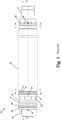
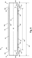
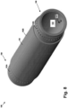
Figures 5-12 depict various aspects of various embodiments of a one-piece production/annulus bore stab 100 with integral flow paths.Figure 5 is a side view of one illustrative embodiment of a one-piece production/annulus bore stab 100 disclosed herein.Figure 6 is a cross-sectional view of the illustrative one-piece production/annulus bore stab 100 taken through the axial length of the production/annulus bore stab 100.Figure 7 is a transverse cross-sectional view of the production/annulus bore stab 100 taken where indicated inFigure 5 .Figure 8 is a perspective view of the depicted example of a one-piece production/annulus bore stab 100.Figure 9 is a cross-sectional perspective view of the one-piece production/annulus bore stab 100 taken through the axial length of theproduction bore stab 100. - In general, one illustrative embodiment of a novel production/
annulus bore stab 100 disclosed herein comprises a unitary, one-piece body 102 with afirst end 104 and asecond end 106. Thebody 102 has an outermostcylindrical surface 102S and an innercylindrical surface 102T. Also depicted inFigure 6 are acentral bore 105 and anaxial centerline 107 of the one-piece production/annulus bore stab 100. The physical dimensions of the one-piece body 102, e.g., theaxial length 102L, outside diameters, the inside diameter of the one-piece production/annulus bore stab 100, as well as the radial thickness of thebody 102 at various locations along theaxial length 102L, may vary depending upon the particular application. - A plurality of individual and
separate flow paths 103 are formed within thebody 102. Each of theflow paths 103 has a first inlet/outlet 103A positioned at a first end (adjacent end 104) of theflow path 103 and a second inlet/outlet 103B that is positioned at a second end (adjacent end 106) of thefluid flow path 103. The first inlet/outlets 103A are positioned in or extend through a first cylindricalouter surface 102X of the one-piece body 102, while the second inlet/outlets 103B are positioned in or extend through a second cylindricalouter surface 102Y of the one-piece body 102. The outside diameters of the first and second cylindricalouter surfaces fluid flow paths 103 are formed or defined entirely within the one-piece body 102. Moreover, in one illustrative embodiment, each of the individualfluid flow paths 103 are fluidly isolated from one another within the one-piece body 102. As depicted, in one illustrative embodiment, each of the plurality ofindividual flow paths 103 extends for substantially the entireaxial length 102L of the one-piece body 102. - The routing and configuration of the
individual flow paths 103 within the one-piece body 102 may vary depending upon the particular application. In one particularly illustrative example, each of the plurality ofindividual flow paths 103 may comprise anaxial length portion 103X having acenterline 103Y that is substantially parallel to thelongitudinal centerline 107. In other applications, all or part of the one or more of theflow paths 103 may be oriented in a non-parallel relationship with respect to thelongitudinal centerline 107. For example, at least portions of theflow paths 103 may be curved or otherwise non-linear with respect to the centerline 107 (or some other reference). Thus, the configuration or positioning of portions of theflow paths 103 with respect to the longitudinal centerline 107 (or some other reference) may vary depending upon the particular application. - With continuing reference to
Figure 6 , in this particular example, each of thefluid flow paths 103 comprises a first flowpath transition region 103S between theaxial length portion 103X and the first inlet/outlet 103A, and a second flowpath transition region 103T between theaxial length portion 103X and the second inlet/outlet 103B. As also depicted, aline 103E extending through a center of the first inlet/outlet 103A and intersecting the flow path centerline 103Y at a first end of theaxial length portion 103X defines a first includedangle 125 that is an obtuse angle. Similarly, aline 103F extending through a center of the second inlet/outlet 103B and intersecting the flow path centerline 103Y at a second end of theaxial length portion 103X defines a second includedangle 127 that is an obtuse angle. In some applications, theangles angles flow paths 103 as well as the number offlow paths 103 may vary depending upon the particular application. With reference toFigure 7 , the illustrative one-piece production/annulus bore stab 100 disclosed herein comprises thirty-sixflow paths 103, each of which have a diameter of approximately 6.35 mm (0.25 inches). -
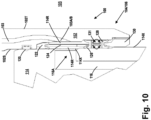
Figure 10 is a cross-sectional view depicting the engagement and positioning of one end of the one-piece production/annulus bore stab 100 relative to another item ofequipment 114, e.g., a tubing hanger or the valve block of a production tree. Also depicted inFigure 10 is anelastomer seal 120, aseal 122, aseal spacer 124, aseal 126, aseal 128, anelastomer seal 131 and aseal retaining ring 130 that is threadingly coupled to thebody 102. All of the illustrative seals and spacers depicted inFigure 10 may or may not be present in all applications. Theequipment 114 comprises at least one annulus fluid flow passageway or path 116 (only one of the annulusfluid flow passageways 116 is shown inFigure 10 ). In one illustrative example, each of the one or more annulusfluid flow paths 116 is adapted to be in fluid communication with a radial gallery (or annulus fluid collection chamber) 116A. In some applications, theequipment 114 may contain a plurality ofsuch collection chambers 116A, each of which may be fluidly isolated from one another. In one illustrative example, the annulusfluid collection chamber 116A may be defined (in whole or part) by the outer diameter (102X or 102Y) of thebody 102 and theinner diameter 114X of theequipment 114. - In one illustrative example, the annulus
fluid collection chamber 116A is adapted to be placed in fluid communication with one or more (and sometimes all) of the annulusfluid flow paths 103 in thebody 102. Theseal spacer 124 may comprise one or more openings that allow fluid to flow freely between theflow paths 103/the annulusfluid collection chamber 116A and the one ormore flow paths 116 in theequipment 114. The illustrative embodiment of the one-piece production/annulus bore stab 100 discussed above may be manufactured using a variety of known manufacturing techniques, e.g., hot isostatic pressing (HIP), 3D printing, etc. -
Figures 11 and12 depict an embodiment of the one-piece production/annulus bore stab 100 wherein theindividual flow paths 103 in thebody 102 are formed by a process that includes drilling a plurality of intersecting bores in thebody 102.Figure 11 depicts the one-piece production/annulus bore stab 100 at a point where a plurality of axial bores 140 (only one of which is shown) have been drilled though the entireaxial length 102L of thebody 102 to define at least part of theaxial length portion 103X of one of theflow paths 103 with acenterline 103Y. In some applications, theaxial bores 140 need not extend throughout the entireaxial length 102L of thebody 102, e.g., thebores 140 may stop within the body at, for example, a location within thebody 102 indicated by the dashed line 144 adjacent theend 106. In some applications, theaxial bores 140 may be drilled in a single pass, e.g., from theend 104 through theend 106. In other applications, theaxial length 102L of the one-piece production borestab 100 may be such that each of theaxial bores 140 is formed by drilling a bore from each of the opposite ends 104, 106 into thebody 102 to form one of theflow paths 103, wherein these separate bores are substantially co-linear with one another (or otherwise in fluid communication with one another) and at least partially engage one another within thebody 102. - Also depicted in
Figure 11 are first and second radial bores 142, 143 that are drilled to intersect with one of the axial bores 140. As indicated, in one illustrative example, the radial bores 142 and 143, respectively, correspond to the first and second inlet/outlet fluid flow paths 103. In the depicted example, theaxial bores 140 were formed prior to the formation of the radial bores 142, 143, but the order could be reversed if desired.Figure 12 depicts the one-piece production borestab 100 afterplugs 150 were secured within theaxial openings 140 at opposite ends thereof. Theplugs 150 may be secured in position using any of a variety of known techniques, e.g., welding, providing a threaded connection between theplugs 150 and theaxial bore 140, etc. Of course, in the example where theaxial bores 140 do not extend throughout the entire axial length of thebody 102, e.g., the case where they stop at location 144 (seeFigure 11 ), then only asingle plug 150 would be required within each of the axial bores 140. With the plug(s) 150 installed, a plurality ofindividual flow paths 103 have been formed within the one-piece body 102. More specifically, in this example, each of the plurality of individual flow paths 103 (formed entirely within the body 102) comprises first and second radially-orientedflow paths axial bores 140, wherein the first radially-orientedflow path 142 terminates at the first inlet/outlet 103A and the second radially-orientedflow path 143 terminates at the second inlet/outlet 103B. In this particular example, a centerline of each of the first and second radially-orientedopenings flow path centerline 103Y of theaxial bore 140. In the example shown inFigures 11 and12 , thebores body 102. In other applications, such bores may be formed by other manufacturing processes, e.g., laser boring, etc. - As will be appreciated by those skilled in the art after a complete reading of the present application, one illustrative example of a novel one-piece production/
annulus bore stab 100 with integralfluid flow paths 103 formed entirely within the one-piece body 102 disclosed herein provides some distinct advantages relative to prior art production bore stabs and annulus bore stabs. One problem associated with the illustrative prior art production/annulus stab body 10 discussed in the background section of this application involved maintaining seal integrity under operational conditions. That is, each of the innerproduction stab body 11 and the outerannulus stab body 12 are essentially two separate pressure vessels that may experience different thermal loads (e.g., different temperatures) when in service. Such different thermal loads may cause the innerproduction stab body 11 and the outerannulus stab body 12 to exhibit different amounts of radial and/or axial expansion under certain operating conditions. In turn, such differences in radial and/or axial expansion between theinner production stab 11 and theouter annulus stab 12 can cause problems with respect to maintaining the integrity of the seals, e.g., theprimary metal seal 19 and/or thesecondary metal seal 17, on the prior art production/annulus stab 10. The novel one-pieceproduction annulus stab 100 may help to eliminate or at least reduce this problem due to its one-piece construction. - Another problem with the prior art production/
annulus stab 10 was related to the required radial thickness of the innerproduction stab body 11 and/or the outerannulus stab body 12. That is, each of the innerproduction stab body 11 and the outerannulus stab body 12 are essentially two separate pressure vessels that must be designed for the unique loading conditions experienced by each of these separate pressure vessels during operation. More specifically, since there were no lateral seals between thefluid flow paths 27, the exterior surface of the innerproduction stab body 11 was subjected to an external pressure which tended to compress the innerproduction stab body 11. The radial thickness of the innerproduction stab body 11 was increased to resist this external pressure. Additionally, due to the two-piece configuration of the prior art production/annulus borestab 10, the outerannulus stab body 12 was subjected to an internal pressure (the annulus pressure) at its inner surface due to the presence of thefluid flow paths 27. Thus, the radial thickness of this outerannulus stab body 12 had to be sufficient to accommodate this additional pressure loading. In contrast, the novel one-piece production/annulus bore stab 100 disclosed herein is essentially a single pressure vessel. Of course, that single pressure vessel will also have to be designed and sized for all loading conditions, e.g., internal and external pressures. However, due to the unique one-piece configuration of the production/annulus bore stab 100 disclosed herein, as well as the placement of the individualfluid flow paths 103 within thebody 102, the overall radial thickness of thebody 102 will typically be less than the combined radial thicknesses of the innerproduction stab body 11 and the outerannulus stab body 12. Other advantages of the various embodiments of the one-piece production borestab 100 disclosed herein may be apparent to those skilled in the art after a complete reading of the present application. -
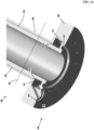
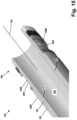
Figures 13-15 depict various aspects of yet another embodiment of a production/ annulus bore stab with integral flow paths disclosed herein.Figure 13 is perspective view of this illustrative example of a production/annulus bore stab 100 disclosed herein.Figure 14 is an enlarged cross-sectional perspective view of thefirst end 104 of the production/annulus bore stab 100.Figure 15 is an enlarged cross-sectional perspective view of thesecond end 106 of the production/annulus bore stab 100. Unless specifically noted otherwise, the above descriptions of various like-number components or features apply equally to this embodiment of the production/annulus bore stab 100. - As before, in this embodiment, the individual and
separate flow paths 103 are formed within thebody 102. In this example, the production/annulus bore stab 100 comprises aflange 150 at the first (or upper end) 104. Theflange 150 is adapted to be coupled to another item of equipment, such as a valve block of a Christmas tree, etc. Also depicted is a radial gallery (or annulus fluid collection chamber) 151, an annulus fluid inlet/outlet 152, aproduction seal groove 153 and anannulus seal groove 154. Seals (not shown) will be positioned in theseal grooves outlet 103A of each of theindividual flow paths 103 intersects theradial gallery 151, while the second inlet/outlet 103B of each of theflow paths 103 are positioned in or extend through the second cylindricalouter surface 102Y of thebody 102. Theflange 150 may be formed integral with thebody 102 or it may be a separate component that that is welded to the remaining portion or the body at, for example, the location of the dashed-line 155 (seeFigure 14 ). For purposes of the attached claims, either of these configurations should be understood to constitute a one-piece body 102 for the production/annulus bore stab 100. - The particular embodiments disclosed above are illustrative only, as the disclosed subject matter may be modified and practiced in different but equivalent manners apparent to those skilled in the art having the benefit of the teachings herein. For example, the process steps set forth above may be performed in a different order. Furthermore, no limitations are intended to the details of construction or design herein shown, other than as described in the claims below. It is therefore evident that the particular embodiments disclosed above may be altered or modified and all such variations are considered within the scope and spirit of the claimed subject matter. Note that the use of terms, such as "first," "second," "third" or "fourth" to describe various processes or structures in this specification and in the attached claims is only used as a shorthand reference to such steps/structures and does not necessarily imply that such steps/structures are performed/formed in that ordered sequence. Of course, depending upon the exact claim language, an ordered sequence of such processes may or may not be required. Accordingly, the protection sought herein is as set forth in the claims below.
- Although the present invention is defined in the claims, it should be understood that the present invention can also (alternatively) be defined in accordance with the following embodiments:
- 1. A production/annulus bore stab (100), comprising:
- a one-piece body (102) comprising a first cylindrical outer surface (102X) and a second cylindrical outer surface (102Y); and
- a plurality of individual fluid flow paths defined entirely within the one-piece body (102), each of the individual fluid flow paths (103) being fluidly isolated from one another within the one-piece body, each of the fluid flow paths (103) comprising a first inlet/outlet (103A) at a first end of the fluid flow path (103) and a second inlet/outlet (103B) at a second end of the fluid flow path (103), wherein the first inlet/outlet (103A) is positioned in the first cylindrical outer surface (102X) and the second inlet/outlet (103B) is positioned in the second cylindrical outer surface (102Y), wherein at least a portion of the one-piece body (102) is adapted to be positioned within and sealingly coupled to an item of equipment (114) that has at least one fluid flow path (116) formed therein such that the at least one fluid flow path (116) within the item of equipment (114) is in fluid communication with at least one of the plurality of individual fluid flow paths (103) defined within the one-piece body (102).
- 2. The production/annulus bore stab (100) of embodiment 1, wherein the one-piece body (102) has an axial length (102L) and wherein each of the plurality of individual flow paths (103) extends for substantially the entire axial length of the one-piece body (102).
- 3. The production/annulus bore stab (100) of embodiment 1, wherein the one-piece body (102) has an axial length (102L) and a longitudinal center line (107) and wherein each of the plurality of individual flow paths (103) comprises an axial length portion (103X) having a centerline (103Y) that is substantially parallel to the longitudinal centerline (107).
- 4. The production/annulus bore stab (100) of
embodiment 3, wherein each of the plurality of individual flow paths (103) comprises a first flow path transition region (103S) between the axial length portion (103X) and the first inlet/outlet (103A) and a second flow path transition region (103T) between the axial length portion (103X) and the second inlet/outlet (103). - 5. The production/annulus bore stab (100) of
embodiment 3, wherein a line (103E) extending through a center of the first inlet/outlet (103A) and intersecting the flow path centerline (103Y) at a first end of the axial length portion (103X) defines a first angle (125) that is an obtuse angle. - 6. The production/annulus bore stab (100) of embodiment 5, wherein a line (103F) extending through a center of the second inlet/outlet (103B) and intersecting the flow path centerline (103Y) at a second end of the axial length portion (103X) defines a second angle (127) that is an obtuse angle.
- 7. The production/annulus bore stab (100) of
embodiment 3, wherein each of the plurality of individual flow paths (103) comprises first and second radially-oriented flow paths (142, 143) that are in fluid communication with the axial length portion (103X), the first radially-oriented flow path (142) terminating at the first inlet/outlet 103A, the second radially-oriented flow path (143) terminating at the second inlet/outlet (103B), wherein a centerline of each of the first and second radially-oriented openings (142, 143) is positioned substantially normal to the flow path centerline (103Y). - 8. The production/annulus bore stab (100) of embodiment 1, wherein each of the plurality of individual flow paths (103) is defined by a plurality of drilled bores (140, 142, 143) in the one-piece body (102)
- 9. The production/annulus bore stab (100) of embodiment 1, wherein the one-piece body (102) comprises an axial length (102L) and a longitudinal centerline (107) and wherein each of the plurality of individual flow paths (103) is defined by:
- an axial bore (140) that extends for substantially the entire axial length (102L) of the one-piece body (102), the axial bore (140) comprising a centerline (103Y) that is substantially parallel to the longitudinal centerline (107);
- a first radially-oriented bore (142) that intersects the axial bore (140), the first inlet/outlet (103A) being located adjacent a first end of the first radially-oriented bore (142); and
- a second radially-oriented bore (143) that intersects the axial bore (140), the second inlet/outlet (103B) being located adjacent a first end of the second radially-oriented bore (143).
- 10. The production/annulus bore stab (100) of embodiment 1, wherein a diameter of the first cylindrical outer surface (102X) is approximately the same as a diameter of the second cylindrical outer surface (102Y).
- 11. The production/annulus bore stab (100) of embodiment 1, wherein the item of equipment (114) is one of a tubing hanger or a valve block of a production tree.
- 12. A production/annulus bore stab (100), comprising:
- a one-piece body (102) comprising an outer surface (102Y) and a flange (150);
- a annulus fluid collection chamber (151) within the flange (150);
- an annulus fluid inlet/outlet (152) in fluid communication with the annulus fluid collection chamber (151); and
- a plurality of individual fluid flow paths defined entirely within the one-piece body (102), each of the individual fluid flow paths (103) being fluidly isolated from one another within at least a portion of the one-piece body, each of the fluid flow paths (103) comprising a first inlet/outlet (103A) at a first end of the fluid flow path (103) and a second inlet/outlet (103B) at a second end of the fluid flow path (103), wherein the first inlet/outlet (103A) intersects the annulus fluid collection chamber (151) second inlet/outlet (103B) is positioned in the outer surface (102Y), wherein the flange (150) is adapted to be coupled to an item of equipment (114) that has at least one fluid flow path (116) formed therein such that the at least one fluid flow path (116) within the item of equipment (114) is in fluid communication with at least one of the plurality of individual fluid flow paths (103) defined within the one-piece body (102).
- 13. The production/annulus bore stab (100) of
embodiment 12, wherein the item of equipment (114) is one of a tubing hanger or a valve block of a production tree. - 14. A system, comprising:
- an item of equipment (114) comprising at least one fluid flow path (116) formed therein; and
- a production/annulus bore stab (100) comprising:
- a one-piece body (102) comprising a first cylindrical outer surface (102X) and a second cylindrical outer surface (102Y), wherein at least a portion of the one-piece body (102) is positioned within and sealingly coupled to the item of equipment (114); and
- a plurality of individual fluid flow paths defined entirely within the one-piece body (102), each of the individual fluid flow paths (103) being fluidly isolated from one another within the one-piece body (102), each of the fluid flow paths (103) comprising a first inlet/outlet (103A) at a first end of the fluid flow path (103) and a second inlet/outlet (103B) at a second end of the fluid flow path (103), wherein the first inlet/outlet (103A) is positioned in the first cylindrical outer surface (102X) and the second inlet/outlet (103B) is positioned in the second cylindrical outer surface (102Y), wherein the at least one fluid flow path (116) within the item of equipment (114) is in fluid communication with at least one of the plurality of individual fluid flow paths (103) defined within the one-piece body (102).
- 15. The system of
embodiment 14, wherein the item of equipment (114) is one of a tubing hanger or a valve block of a production tree. - 16. A system, comprising:
- an item of equipment (114) comprising at least one fluid flow path formed therein (116); and
- a production/annulus bore stab (100) comprising:
- a one-piece body (102) comprising an outer surface (102Y) and a flange (150), wherein the flange (150) is coupled to the item of equipment (114);
- an annulus fluid collection chamber (151) within the flange (150);
- an annulus fluid inlet/outlet (152) in fluid communication with the annulus fluid collection chamber (151), wherein the annulus fluid inlet/outlet (152) is sealingly coupled to the item of equipment (114); and
- a plurality of individual fluid flow paths (103) defined entirely within the one-piece body (102), each of the individual fluid flow paths (103) being fluidly isolated from one another within at least a portion of the one-piece body (102), each of the fluid flow paths (103) comprising a first inlet/outlet (103A) at a first end of the fluid flow path (103) and a second inlet/outlet (103B) at a second end of the fluid flow path (103), wherein the first inlet/outlet (103A) intersects the annulus fluid collection chamber (151) and the second inlet/outlet (103B) is positioned in the outer surface (102Y), wherein the annulus fluid inlet/outlet (152) is sealingly coupled to the item of equipment (114) such that the at least
- one fluid flow path (116) within the item of equipment (114) is in fluid communication with at least one of the plurality of individual fluid flow paths (103) defined within the one-piece body (102).
- 17. The system of
embodiment 16, wherein the item of equipment (114) is one of a tubing hanger or a valve block of a production tree.
Claims (10)
- A system comprising:an item of equipment (114) that has at least one fluid flow path (116) formed therein; anda production/annulus bore stab (100) comprisingi) a one-piece body (102) comprising a first cylindrical outer surface (102X), a second cylindrical outer surface (102Y), and an inner cylindrical surface (102T),
andii) a plurality of individual fluid flow paths defined entirely within the one-piece body (102), each of the individual fluid flow paths (103) being fluidly isolated from one another within the one-piece body, each of the fluid flow paths (103) comprising a first inlet/outlet (103A) at a first end of the fluid flow path (103) and a second inlet/outlet (103B) at a second end of the fluid flow path (103),wherein the first inlet/outlet (103A) is positioned in the first cylindrical outer surface (102X) and the second inlet/outlet (103B) is positioned in the second cylindrical outer surface (102Y),wherein at least a portion of the one-piece body (102) is adapted to be positioned within and sealingly coupled to the item of equipment (114) such that each of the at least one fluid flow paths (116) within the item of equipment (114) is in fluid communication with an annulus fluid collection chamber (116A), wherein the annulus fluid collection chamber (116A) is defined in whole or part by the first or second cylindrical outer surface (102X, 102Y) of the one-piece body (102) and an inner diameter (114X) of the item of equipment (114) such that the annulus fluid collection chamber (116A) is placed in fluid communication with at least one of the plurality of individual fluid flow paths (103) defined within the one-piece body (102). - The system of claim 1, wherein the annulus fluid collection chamber (116A) is configured to be in fluid communication with a plurality of the individual fluid flow paths (103) in the body (102).
- The system of claim 1 or 2, wherein the annulus fluid collection chamber (116A) is configured to be in fluid communication with all of the individual fluid flow paths (103) in the body (102).
- The system of claim 2 or 3, wherein the production/annulus bore stab (100) further comprises a seal spacer (124) that comprises openings configured to allow fluid to flow between the individual fluid flow paths (103), the annulus fluid collection chamber (116A), and the at least one fluid flow path (116) within the item of equipment (114).
- The system of claim 1, wherein the production/annulus bore stab (100) comprises a plurality of annulus fluid collection chamber (116A) each fluidly isolated from one another.
- The system of claim 1, wherein the annulus fluid collection chamber (116A) is defined in whole by the first or second cylindrical outer surface (102X, 102Y) of the one-piece body (102) and the inner diameter (114X) of the item of equipment (114).
- The system of claim 1, wherein the one-piece body (102) has an axial length (102L) and wherein each of the plurality of individual flow paths (103) extends for substantially the entire axial length of the one-piece body (102).
- The system of any preceding claim, wherein the one-piece body (102) has an axial length (102L) and a longitudinal center line (107) and wherein each of the plurality of individual flow paths (103) comprises an axial length portion (103X) having a centerline (103Y) that is substantially parallel to the longitudinal centerline (107).
- The system of any preceding claim, wherein a diameter of the first cylindrical outer surface (102X) is approximately the same as a diameter of the second cylindrical outer surface (102Y).
- The system of any preceding claim, wherein the item of equipment (114) is one of a tubing hanger or a valve block of a production tree.
Applications Claiming Priority (3)
| Application Number | Priority Date | Filing Date | Title |
|---|---|---|---|
| US16/267,960 US10689921B1 (en) | 2019-02-05 | 2019-02-05 | One-piece production/annulus bore stab with integral flow paths |
| EP20707960.9A EP3921507B1 (en) | 2019-02-05 | 2020-01-27 | One-piece production/annulus bore stab with integral flow paths |
| PCT/US2020/015190 WO2020163103A1 (en) | 2019-02-05 | 2020-01-27 | One-piece production/annulus bore stab with integral flow paths |
Related Parent Applications (1)
| Application Number | Title | Priority Date | Filing Date |
|---|---|---|---|
| EP20707960.9A Division EP3921507B1 (en) | 2019-02-05 | 2020-01-27 | One-piece production/annulus bore stab with integral flow paths |
Publications (2)
| Publication Number | Publication Date |
|---|---|
| EP4151826A1 true EP4151826A1 (en) | 2023-03-22 |
| EP4151826B1 EP4151826B1 (en) | 2024-07-17 |
Family
ID=69724129
Family Applications (2)
| Application Number | Title | Priority Date | Filing Date |
|---|---|---|---|
| EP20707960.9A Active EP3921507B1 (en) | 2019-02-05 | 2020-01-27 | One-piece production/annulus bore stab with integral flow paths |
| EP22205847.1A Active EP4151826B1 (en) | 2019-02-05 | 2020-01-27 | One-piece production/annulus bore stab with integral flow paths |
Family Applications Before (1)
| Application Number | Title | Priority Date | Filing Date |
|---|---|---|---|
| EP20707960.9A Active EP3921507B1 (en) | 2019-02-05 | 2020-01-27 | One-piece production/annulus bore stab with integral flow paths |
Country Status (3)
| Country | Link |
|---|---|
| US (7) | US10689921B1 (en) |
| EP (2) | EP3921507B1 (en) |
| WO (1) | WO2020163103A1 (en) |
Families Citing this family (3)
| Publication number | Priority date | Publication date | Assignee | Title |
|---|---|---|---|---|
| US11885194B2 (en) | 2018-12-12 | 2024-01-30 | Fmc Technologies, Inc. | Rotating indexing coupling (RIC) assembly for installation and orientation of a subsea production tree |
| US10689921B1 (en) * | 2019-02-05 | 2020-06-23 | Fmc Technologies, Inc. | One-piece production/annulus bore stab with integral flow paths |
| WO2022256342A1 (en) | 2021-05-29 | 2022-12-08 | Onesubsea Ip Uk Limited | Flow path and bore management system and method |
Citations (4)
| Publication number | Priority date | Publication date | Assignee | Title |
|---|---|---|---|---|
| US4695190A (en) * | 1986-03-04 | 1987-09-22 | Smith International, Inc. | Pressure-balanced stab connection |
| US20060260799A1 (en) * | 2005-05-18 | 2006-11-23 | Nautilus Marine Technologies, Inc. | Universal tubing hanger suspension assembly and well completion system and method of using same |
| US20090211761A1 (en) * | 2005-05-18 | 2009-08-27 | Argus Subsea, Inc. | Oil and gas well completion system and method of installation |
| US20150053412A1 (en) * | 2013-08-20 | 2015-02-26 | Cameron International Corporation | Production System Including Tubing Hanger with Valve |
Family Cites Families (35)
| Publication number | Priority date | Publication date | Assignee | Title |
|---|---|---|---|---|
| US4109712A (en) * | 1977-08-01 | 1978-08-29 | Regan Offshore International, Inc. | Safety apparatus for automatically sealing hydraulic lines within a sub-sea well casing |
| US4333526A (en) * | 1979-05-10 | 1982-06-08 | Hughes Tool Company | Annulus valve |
| US4497369A (en) | 1981-08-13 | 1985-02-05 | Combustion Engineering, Inc. | Hydraulic control of subsea well equipment |
| US4836305A (en) * | 1985-05-06 | 1989-06-06 | Pangaea Enterprises, Inc. | Drill pipes and casings utilizing multi-conduit tubulars |
| US4641841A (en) * | 1985-08-26 | 1987-02-10 | Hughes Tool Company | Metal seal for a tubular connection |
| GB8625290D0 (en) * | 1986-10-22 | 1986-11-26 | Wood Group Drilling & Prod | Monitoring apparatus |
| DE3868634D1 (en) * | 1988-07-06 | 1992-04-02 | Cooper Ind Inc | CLEARING VALVE FOR A CONCENTRIC PIPE HEAD. |
| FR2663978B1 (en) * | 1990-06-29 | 1995-12-15 | Elf Aquitaine | PRODUCTION TUBE WITH INTEGRATED HYDRAULIC LINE. |
| SG52153A1 (en) * | 1994-07-11 | 1998-09-28 | Dril Quip Inc | Subsea wellhead apparatus |
| US5503230A (en) * | 1994-11-17 | 1996-04-02 | Vetco Gray Inc. | Concentric tubing hanger |
| NO310585B1 (en) * | 1998-03-25 | 2001-07-23 | Reslink As | Pipe connection for connection of double walled pipes |
| US6666754B1 (en) | 2000-01-18 | 2003-12-23 | Advanced Micro Devices, Inc. | Method and apparatus for determining CMP pad conditioner effectiveness |
| GB2366027B (en) | 2000-01-27 | 2004-08-18 | Bell & Howell Postal Systems | Address learning system and method for using same |
| AU4778401A (en) | 2000-03-24 | 2001-10-08 | Fmc Corp | Tubing head seal assembly |
| EP1278934B1 (en) | 2000-03-24 | 2005-08-24 | FMC Technologies, Inc. | Tubing hanger system with gate valve |
| US6491097B1 (en) * | 2000-12-14 | 2002-12-10 | Halliburton Energy Services, Inc. | Abrasive slurry delivery apparatus and methods of using same |
| US6659181B2 (en) | 2001-11-13 | 2003-12-09 | Cooper Cameron Corporation | Tubing hanger with annulus bore |
| US6634427B1 (en) * | 2002-03-11 | 2003-10-21 | Aps Technology, Inc. | Drill string section with internal passage |
| US7063160B2 (en) * | 2002-07-30 | 2006-06-20 | Vetco Gray Inc. | Non-orienting tubing hanger system with a flow cage |
| US7331396B2 (en) | 2004-03-16 | 2008-02-19 | Dril-Quip, Inc. | Subsea production systems |
| GB2440940B (en) | 2006-08-18 | 2009-12-16 | Cameron Internat Corp Us | Wellhead assembly |
| US8393354B2 (en) | 2007-11-26 | 2013-03-12 | Cameron International Corporation | Self-sealing hydraulic control line coupling |
| US8240389B2 (en) | 2008-09-26 | 2012-08-14 | Vetco Gray Inc. | Combined tree stab and control interface |
| BRPI0919913A2 (en) | 2008-10-28 | 2016-02-16 | Cameron Int Corp | underwater completion with a wellhead annular space access adapter |
| GB2479552B (en) * | 2010-04-14 | 2015-07-08 | Aker Subsea Ltd | Subsea wellhead providing controlled access to a casing annulus |
| US9534466B2 (en) | 2012-08-31 | 2017-01-03 | Onesubsea Ip Uk Limited | Cap system for subsea equipment |
| BR112015032254A2 (en) * | 2013-06-28 | 2017-07-25 | Schlumberger Technology Bv | system for use in an underwater well, system for use in a well, and method. |
| GB2520701B (en) * | 2013-11-27 | 2016-05-11 | Shearer David | A drill string stabiliser and associated equipment and methods |
| US10145206B2 (en) * | 2013-12-23 | 2018-12-04 | Halliburton Energy Services, Inc. | Adjustable choke device for a production tube |
| US10393302B2 (en) * | 2014-06-18 | 2019-08-27 | United Technologies Corporation | Double wall tube bolted flange fitting |
| GB2555320B (en) * | 2015-07-09 | 2021-05-12 | Halliburton Energy Services Inc | Modular manifold system for an electrohydraulic control system |
| US9702215B1 (en) | 2016-02-29 | 2017-07-11 | Fmc Technologies, Inc. | Subsea tree and methods of using the same |
| US10633966B2 (en) | 2017-12-06 | 2020-04-28 | Onesubsea Ip Uk Limited | Subsea isolation sleeve system |
| US10794147B2 (en) | 2018-05-04 | 2020-10-06 | Baker Hughes, A Ge Company, Llc | Downhole component including a unitary body having an internal annular chamber and fluid passages |
| US10689921B1 (en) * | 2019-02-05 | 2020-06-23 | Fmc Technologies, Inc. | One-piece production/annulus bore stab with integral flow paths |
-
2019
- 2019-02-05 US US16/267,960 patent/US10689921B1/en active Active
-
2020
- 2020-01-27 WO PCT/US2020/015190 patent/WO2020163103A1/en not_active Ceased
- 2020-01-27 EP EP20707960.9A patent/EP3921507B1/en active Active
- 2020-01-27 EP EP22205847.1A patent/EP4151826B1/en active Active
- 2020-06-19 US US16/906,596 patent/US11180963B2/en active Active
-
2021
- 2021-10-20 US US17/506,274 patent/US11486207B2/en active Active
- 2021-12-15 US US17/644,451 patent/US11441365B2/en active Active
-
2022
- 2022-09-12 US US17/931,432 patent/US11686164B2/en active Active
-
2023
- 2023-05-25 US US18/202,122 patent/US11939823B2/en active Active
-
2024
- 2024-03-22 US US18/613,929 patent/US12305454B2/en active Active
Patent Citations (4)
| Publication number | Priority date | Publication date | Assignee | Title |
|---|---|---|---|---|
| US4695190A (en) * | 1986-03-04 | 1987-09-22 | Smith International, Inc. | Pressure-balanced stab connection |
| US20060260799A1 (en) * | 2005-05-18 | 2006-11-23 | Nautilus Marine Technologies, Inc. | Universal tubing hanger suspension assembly and well completion system and method of using same |
| US20090211761A1 (en) * | 2005-05-18 | 2009-08-27 | Argus Subsea, Inc. | Oil and gas well completion system and method of installation |
| US20150053412A1 (en) * | 2013-08-20 | 2015-02-26 | Cameron International Corporation | Production System Including Tubing Hanger with Valve |
Also Published As
| Publication number | Publication date |
|---|---|
| US20220106843A1 (en) | 2022-04-07 |
| US20230003088A1 (en) | 2023-01-05 |
| US20230304365A1 (en) | 2023-09-28 |
| US12305454B2 (en) | 2025-05-20 |
| WO2020163103A1 (en) | 2020-08-13 |
| US11441365B2 (en) | 2022-09-13 |
| US20220034175A1 (en) | 2022-02-03 |
| EP3921507B1 (en) | 2022-11-09 |
| EP4151826B1 (en) | 2024-07-17 |
| US10689921B1 (en) | 2020-06-23 |
| BR112021015460A2 (en) | 2021-10-05 |
| US11686164B2 (en) | 2023-06-27 |
| US11180963B2 (en) | 2021-11-23 |
| US20240410236A1 (en) | 2024-12-12 |
| EP3921507A1 (en) | 2021-12-15 |
| US11939823B2 (en) | 2024-03-26 |
| US11486207B2 (en) | 2022-11-01 |
| US20200318442A1 (en) | 2020-10-08 |
Similar Documents
| Publication | Publication Date | Title |
|---|---|---|
| US11939823B2 (en) | One-piece production/annulus bore stab with integral flow paths | |
| US6681852B2 (en) | Tubing hanger shuttle valve | |
| US10844687B2 (en) | Wellhead seal energized by fluid pressure | |
| US8251139B2 (en) | System and method for sealing couplings in downhole tubing strings | |
| US9689241B2 (en) | Gas lift valve assemblies having fluid flow barrier and methods of assembling same | |
| WO2008020232A2 (en) | Wellhead assembly | |
| US20160160605A1 (en) | Configurable Subsea Tree Master Valve Block | |
| US10947804B2 (en) | Metal-to-metal annulus wellhead style seal with pressure energized from above and below | |
| US10161213B2 (en) | Internal and external pressure seal assembly | |
| US7063160B2 (en) | Non-orienting tubing hanger system with a flow cage | |
| US9200498B2 (en) | Flow control hanger and polished bore receptacle | |
| US8752634B2 (en) | Segmented seal ring and support of same | |
| EP3149267B1 (en) | Fluid line exit block with dual metal-to-metal sealing | |
| BR112021015460B1 (en) | ANNULAR/PRODUCTION HOLE STAB AND SYSTEM | |
| US10246964B2 (en) | Casing hanger retention system | |
| US20030025324A1 (en) | High-pressure pipe element consisting of hooped tube sections | |
| WO2014160634A2 (en) | Thin wall active casing hanger | |
| GB2392683A (en) | A completion having an annulus valve | |
| NO20170153A1 (en) | Hanger running tool |
Legal Events
| Date | Code | Title | Description |
|---|---|---|---|
| PUAI | Public reference made under article 153(3) epc to a published international application that has entered the european phase |
Free format text: ORIGINAL CODE: 0009012 |
|
| STAA | Information on the status of an ep patent application or granted ep patent |
Free format text: STATUS: REQUEST FOR EXAMINATION WAS MADE |
|
| 17P | Request for examination filed |
Effective date: 20221107 |
|
| AC | Divisional application: reference to earlier application |
Ref document number: 3921507 Country of ref document: EP Kind code of ref document: P |
|
| AK | Designated contracting states |
Kind code of ref document: A1 Designated state(s): AL AT BE BG CH CY CZ DE DK EE ES FI FR GB GR HR HU IE IS IT LI LT LU LV MC MK MT NL NO PL PT RO RS SE SI SK SM TR |
|
| GRAP | Despatch of communication of intention to grant a patent |
Free format text: ORIGINAL CODE: EPIDOSNIGR1 |
|
| STAA | Information on the status of an ep patent application or granted ep patent |
Free format text: STATUS: GRANT OF PATENT IS INTENDED |
|
| INTG | Intention to grant announced |
Effective date: 20240319 |
|
| GRAS | Grant fee paid |
Free format text: ORIGINAL CODE: EPIDOSNIGR3 |
|
| GRAA | (expected) grant |
Free format text: ORIGINAL CODE: 0009210 |
|
| STAA | Information on the status of an ep patent application or granted ep patent |
Free format text: STATUS: THE PATENT HAS BEEN GRANTED |
|
| AC | Divisional application: reference to earlier application |
Ref document number: 3921507 Country of ref document: EP Kind code of ref document: P |
|
| AK | Designated contracting states |
Kind code of ref document: B1 Designated state(s): AL AT BE BG CH CY CZ DE DK EE ES FI FR GB GR HR HU IE IS IT LI LT LU LV MC MK MT NL NO PL PT RO RS SE SI SK SM TR |
|
| P01 | Opt-out of the competence of the unified patent court (upc) registered |
Free format text: CASE NUMBER: APP_36899/2024 Effective date: 20240620 |
|
| REG | Reference to a national code |
Ref country code: CH Ref legal event code: EP |
|
| REG | Reference to a national code |
Ref country code: DE Ref legal event code: R096 Ref document number: 602020034328 Country of ref document: DE |
|
| REG | Reference to a national code |
Ref country code: IE Ref legal event code: FG4D |
|
| REG | Reference to a national code |
Ref country code: LT Ref legal event code: MG9D |
|
| REG | Reference to a national code |
Ref country code: NL Ref legal event code: MP Effective date: 20240717 |
|
| PG25 | Lapsed in a contracting state [announced via postgrant information from national office to epo] |
Ref country code: PT Free format text: LAPSE BECAUSE OF FAILURE TO SUBMIT A TRANSLATION OF THE DESCRIPTION OR TO PAY THE FEE WITHIN THE PRESCRIBED TIME-LIMIT Effective date: 20241118 |
|
| REG | Reference to a national code |
Ref country code: AT Ref legal event code: MK05 Ref document number: 1704316 Country of ref document: AT Kind code of ref document: T Effective date: 20240717 |
|
| PG25 | Lapsed in a contracting state [announced via postgrant information from national office to epo] |
Ref country code: NL Free format text: LAPSE BECAUSE OF FAILURE TO SUBMIT A TRANSLATION OF THE DESCRIPTION OR TO PAY THE FEE WITHIN THE PRESCRIBED TIME-LIMIT Effective date: 20240717 |
|
| PG25 | Lapsed in a contracting state [announced via postgrant information from national office to epo] |
Ref country code: PT Free format text: LAPSE BECAUSE OF FAILURE TO SUBMIT A TRANSLATION OF THE DESCRIPTION OR TO PAY THE FEE WITHIN THE PRESCRIBED TIME-LIMIT Effective date: 20241118 Ref country code: NL Free format text: LAPSE BECAUSE OF FAILURE TO SUBMIT A TRANSLATION OF THE DESCRIPTION OR TO PAY THE FEE WITHIN THE PRESCRIBED TIME-LIMIT Effective date: 20240717 |
|
| PG25 | Lapsed in a contracting state [announced via postgrant information from national office to epo] |
Ref country code: FI Free format text: LAPSE BECAUSE OF FAILURE TO SUBMIT A TRANSLATION OF THE DESCRIPTION OR TO PAY THE FEE WITHIN THE PRESCRIBED TIME-LIMIT Effective date: 20240717 Ref country code: GR Free format text: LAPSE BECAUSE OF FAILURE TO SUBMIT A TRANSLATION OF THE DESCRIPTION OR TO PAY THE FEE WITHIN THE PRESCRIBED TIME-LIMIT Effective date: 20241018 Ref country code: PL Free format text: LAPSE BECAUSE OF FAILURE TO SUBMIT A TRANSLATION OF THE DESCRIPTION OR TO PAY THE FEE WITHIN THE PRESCRIBED TIME-LIMIT Effective date: 20240717 |
|
| PG25 | Lapsed in a contracting state [announced via postgrant information from national office to epo] |
Ref country code: BG Free format text: LAPSE BECAUSE OF FAILURE TO SUBMIT A TRANSLATION OF THE DESCRIPTION OR TO PAY THE FEE WITHIN THE PRESCRIBED TIME-LIMIT Effective date: 20240717 |
|
| PG25 | Lapsed in a contracting state [announced via postgrant information from national office to epo] |
Ref country code: LV Free format text: LAPSE BECAUSE OF FAILURE TO SUBMIT A TRANSLATION OF THE DESCRIPTION OR TO PAY THE FEE WITHIN THE PRESCRIBED TIME-LIMIT Effective date: 20240717 |
|
| PG25 | Lapsed in a contracting state [announced via postgrant information from national office to epo] |
Ref country code: IS Free format text: LAPSE BECAUSE OF FAILURE TO SUBMIT A TRANSLATION OF THE DESCRIPTION OR TO PAY THE FEE WITHIN THE PRESCRIBED TIME-LIMIT Effective date: 20241117 Ref country code: AT Free format text: LAPSE BECAUSE OF FAILURE TO SUBMIT A TRANSLATION OF THE DESCRIPTION OR TO PAY THE FEE WITHIN THE PRESCRIBED TIME-LIMIT Effective date: 20240717 |
|
| PG25 | Lapsed in a contracting state [announced via postgrant information from national office to epo] |
Ref country code: HR Free format text: LAPSE BECAUSE OF FAILURE TO SUBMIT A TRANSLATION OF THE DESCRIPTION OR TO PAY THE FEE WITHIN THE PRESCRIBED TIME-LIMIT Effective date: 20240717 |
|
| PG25 | Lapsed in a contracting state [announced via postgrant information from national office to epo] |
Ref country code: ES Free format text: LAPSE BECAUSE OF FAILURE TO SUBMIT A TRANSLATION OF THE DESCRIPTION OR TO PAY THE FEE WITHIN THE PRESCRIBED TIME-LIMIT Effective date: 20240717 Ref country code: RS Free format text: LAPSE BECAUSE OF FAILURE TO SUBMIT A TRANSLATION OF THE DESCRIPTION OR TO PAY THE FEE WITHIN THE PRESCRIBED TIME-LIMIT Effective date: 20241017 |
|
| PG25 | Lapsed in a contracting state [announced via postgrant information from national office to epo] |
Ref country code: RS Free format text: LAPSE BECAUSE OF FAILURE TO SUBMIT A TRANSLATION OF THE DESCRIPTION OR TO PAY THE FEE WITHIN THE PRESCRIBED TIME-LIMIT Effective date: 20241017 Ref country code: PL Free format text: LAPSE BECAUSE OF FAILURE TO SUBMIT A TRANSLATION OF THE DESCRIPTION OR TO PAY THE FEE WITHIN THE PRESCRIBED TIME-LIMIT Effective date: 20240717 Ref country code: LV Free format text: LAPSE BECAUSE OF FAILURE TO SUBMIT A TRANSLATION OF THE DESCRIPTION OR TO PAY THE FEE WITHIN THE PRESCRIBED TIME-LIMIT Effective date: 20240717 Ref country code: IS Free format text: LAPSE BECAUSE OF FAILURE TO SUBMIT A TRANSLATION OF THE DESCRIPTION OR TO PAY THE FEE WITHIN THE PRESCRIBED TIME-LIMIT Effective date: 20241117 Ref country code: HR Free format text: LAPSE BECAUSE OF FAILURE TO SUBMIT A TRANSLATION OF THE DESCRIPTION OR TO PAY THE FEE WITHIN THE PRESCRIBED TIME-LIMIT Effective date: 20240717 Ref country code: GR Free format text: LAPSE BECAUSE OF FAILURE TO SUBMIT A TRANSLATION OF THE DESCRIPTION OR TO PAY THE FEE WITHIN THE PRESCRIBED TIME-LIMIT Effective date: 20241018 Ref country code: FI Free format text: LAPSE BECAUSE OF FAILURE TO SUBMIT A TRANSLATION OF THE DESCRIPTION OR TO PAY THE FEE WITHIN THE PRESCRIBED TIME-LIMIT Effective date: 20240717 Ref country code: ES Free format text: LAPSE BECAUSE OF FAILURE TO SUBMIT A TRANSLATION OF THE DESCRIPTION OR TO PAY THE FEE WITHIN THE PRESCRIBED TIME-LIMIT Effective date: 20240717 Ref country code: BG Free format text: LAPSE BECAUSE OF FAILURE TO SUBMIT A TRANSLATION OF THE DESCRIPTION OR TO PAY THE FEE WITHIN THE PRESCRIBED TIME-LIMIT Effective date: 20240717 Ref country code: AT Free format text: LAPSE BECAUSE OF FAILURE TO SUBMIT A TRANSLATION OF THE DESCRIPTION OR TO PAY THE FEE WITHIN THE PRESCRIBED TIME-LIMIT Effective date: 20240717 |
|
| PG25 | Lapsed in a contracting state [announced via postgrant information from national office to epo] |
Ref country code: DK Free format text: LAPSE BECAUSE OF FAILURE TO SUBMIT A TRANSLATION OF THE DESCRIPTION OR TO PAY THE FEE WITHIN THE PRESCRIBED TIME-LIMIT Effective date: 20240717 Ref country code: RO Free format text: LAPSE BECAUSE OF FAILURE TO SUBMIT A TRANSLATION OF THE DESCRIPTION OR TO PAY THE FEE WITHIN THE PRESCRIBED TIME-LIMIT Effective date: 20240717 Ref country code: SM Free format text: LAPSE BECAUSE OF FAILURE TO SUBMIT A TRANSLATION OF THE DESCRIPTION OR TO PAY THE FEE WITHIN THE PRESCRIBED TIME-LIMIT Effective date: 20240717 |
|
| REG | Reference to a national code |
Ref country code: DE Ref legal event code: R097 Ref document number: 602020034328 Country of ref document: DE |
|
| PG25 | Lapsed in a contracting state [announced via postgrant information from national office to epo] |
Ref country code: EE Free format text: LAPSE BECAUSE OF FAILURE TO SUBMIT A TRANSLATION OF THE DESCRIPTION OR TO PAY THE FEE WITHIN THE PRESCRIBED TIME-LIMIT Effective date: 20240717 |
|
| PG25 | Lapsed in a contracting state [announced via postgrant information from national office to epo] |
Ref country code: CZ Free format text: LAPSE BECAUSE OF FAILURE TO SUBMIT A TRANSLATION OF THE DESCRIPTION OR TO PAY THE FEE WITHIN THE PRESCRIBED TIME-LIMIT Effective date: 20240717 |
|
| PG25 | Lapsed in a contracting state [announced via postgrant information from national office to epo] |
Ref country code: SK Free format text: LAPSE BECAUSE OF FAILURE TO SUBMIT A TRANSLATION OF THE DESCRIPTION OR TO PAY THE FEE WITHIN THE PRESCRIBED TIME-LIMIT Effective date: 20240717 |
|
| PLBE | No opposition filed within time limit |
Free format text: ORIGINAL CODE: 0009261 |
|
| STAA | Information on the status of an ep patent application or granted ep patent |
Free format text: STATUS: NO OPPOSITION FILED WITHIN TIME LIMIT |
|
| 26N | No opposition filed |
Effective date: 20250422 |
|
| REG | Reference to a national code |
Ref country code: DE Ref legal event code: R119 Ref document number: 602020034328 Country of ref document: DE |
|
| REG | Reference to a national code |
Ref country code: CH Ref legal event code: PL |
|
| PG25 | Lapsed in a contracting state [announced via postgrant information from national office to epo] |
Ref country code: SE Free format text: LAPSE BECAUSE OF FAILURE TO SUBMIT A TRANSLATION OF THE DESCRIPTION OR TO PAY THE FEE WITHIN THE PRESCRIBED TIME-LIMIT Effective date: 20240717 |
|
| PG25 | Lapsed in a contracting state [announced via postgrant information from national office to epo] |
Ref country code: MC Free format text: LAPSE BECAUSE OF FAILURE TO SUBMIT A TRANSLATION OF THE DESCRIPTION OR TO PAY THE FEE WITHIN THE PRESCRIBED TIME-LIMIT Effective date: 20240717 Ref country code: LU Free format text: LAPSE BECAUSE OF NON-PAYMENT OF DUE FEES Effective date: 20250127 |
|
| PG25 | Lapsed in a contracting state [announced via postgrant information from national office to epo] |
Ref country code: DE Free format text: LAPSE BECAUSE OF NON-PAYMENT OF DUE FEES Effective date: 20250801 |
|
| PG25 | Lapsed in a contracting state [announced via postgrant information from national office to epo] |
Ref country code: BE Free format text: LAPSE BECAUSE OF NON-PAYMENT OF DUE FEES Effective date: 20250131 |
|
| PG25 | Lapsed in a contracting state [announced via postgrant information from national office to epo] |
Ref country code: CH Free format text: LAPSE BECAUSE OF NON-PAYMENT OF DUE FEES Effective date: 20250131 |
|
| REG | Reference to a national code |
Ref country code: BE Ref legal event code: MM Effective date: 20250131 |
|
| PGFP | Annual fee paid to national office [announced via postgrant information from national office to epo] |
Ref country code: NO Payment date: 20251230 Year of fee payment: 7 |
|
| PG25 | Lapsed in a contracting state [announced via postgrant information from national office to epo] |
Ref country code: IT Free format text: LAPSE BECAUSE OF NON-PAYMENT OF DUE FEES Effective date: 20250127 |
|
| PG25 | Lapsed in a contracting state [announced via postgrant information from national office to epo] |
Ref country code: IE Free format text: LAPSE BECAUSE OF NON-PAYMENT OF DUE FEES Effective date: 20250127 |
|
| PGFP | Annual fee paid to national office [announced via postgrant information from national office to epo] |
Ref country code: GB Payment date: 20260127 Year of fee payment: 7 |
|
| PG25 | Lapsed in a contracting state [announced via postgrant information from national office to epo] |
Ref country code: IT Free format text: LAPSE BECAUSE OF NON-PAYMENT OF DUE FEES Effective date: 20250127 |
|
| PGFP | Annual fee paid to national office [announced via postgrant information from national office to epo] |
Ref country code: IT Payment date: 20260107 Year of fee payment: 7 |
|
| PGRI | Patent reinstated in contracting state [announced from national office to epo] |
Ref country code: IT Effective date: 20250603 |
|
| PGFP | Annual fee paid to national office [announced via postgrant information from national office to epo] |
Ref country code: FR Payment date: 20260128 Year of fee payment: 7 |