EP4151491A1 - Rail-guided carrier system - Google Patents
Rail-guided carrier system Download PDFInfo
- Publication number
- EP4151491A1 EP4151491A1 EP21804596.1A EP21804596A EP4151491A1 EP 4151491 A1 EP4151491 A1 EP 4151491A1 EP 21804596 A EP21804596 A EP 21804596A EP 4151491 A1 EP4151491 A1 EP 4151491A1
- Authority
- EP
- European Patent Office
- Prior art keywords
- rail
- cart
- data
- traveling
- measurement
- Prior art date
- Legal status (The legal status is an assumption and is not a legal conclusion. Google has not performed a legal analysis and makes no representation as to the accuracy of the status listed.)
- Pending
Links
Images




Classifications
-
- B—PERFORMING OPERATIONS; TRANSPORTING
- B61—RAILWAYS
- B61K—AUXILIARY EQUIPMENT SPECIALLY ADAPTED FOR RAILWAYS, NOT OTHERWISE PROVIDED FOR
- B61K9/00—Railway vehicle profile gauges; Detecting or indicating overheating of components; Apparatus on locomotives or cars to indicate bad track sections; General design of track recording vehicles
- B61K9/12—Measuring or surveying wheel-rims
-
- B—PERFORMING OPERATIONS; TRANSPORTING
- B61—RAILWAYS
- B61B—RAILWAY SYSTEMS; EQUIPMENT THEREFOR NOT OTHERWISE PROVIDED FOR
- B61B3/00—Elevated railway systems with suspended vehicles
- B61B3/02—Elevated railway systems with suspended vehicles with self-propelled vehicles
-
- G—PHYSICS
- G01—MEASURING; TESTING
- G01H—MEASUREMENT OF MECHANICAL VIBRATIONS OR ULTRASONIC, SONIC OR INFRASONIC WAVES
- G01H1/00—Measuring characteristics of vibrations in solids by using direct conduction to the detector
- G01H1/003—Measuring characteristics of vibrations in solids by using direct conduction to the detector of rotating machines
-
- G—PHYSICS
- G01—MEASURING; TESTING
- G01H—MEASUREMENT OF MECHANICAL VIBRATIONS OR ULTRASONIC, SONIC OR INFRASONIC WAVES
- G01H3/00—Measuring characteristics of vibrations by using a detector in a fluid
- G01H3/04—Frequency
- G01H3/08—Analysing frequencies present in complex vibrations, e.g. comparing harmonics present
-
- H—ELECTRICITY
- H10—SEMICONDUCTOR DEVICES; ELECTRIC SOLID-STATE DEVICES NOT OTHERWISE PROVIDED FOR
- H10P—GENERIC PROCESSES OR APPARATUS FOR THE MANUFACTURE OR TREATMENT OF DEVICES COVERED BY CLASS H10
- H10P72/00—Handling or holding of wafers, substrates or devices during manufacture or treatment thereof
- H10P72/06—Apparatus for monitoring, sorting, marking, testing or measuring
- H10P72/0604—Process monitoring, e.g. flow or thickness monitoring
-
- H—ELECTRICITY
- H10—SEMICONDUCTOR DEVICES; ELECTRIC SOLID-STATE DEVICES NOT OTHERWISE PROVIDED FOR
- H10P—GENERIC PROCESSES OR APPARATUS FOR THE MANUFACTURE OR TREATMENT OF DEVICES COVERED BY CLASS H10
- H10P72/00—Handling or holding of wafers, substrates or devices during manufacture or treatment thereof
- H10P72/30—Handling or holding of wafers, substrates or devices during manufacture or treatment thereof for conveying, e.g. between different workstations
- H10P72/32—Handling or holding of wafers, substrates or devices during manufacture or treatment thereof for conveying, e.g. between different workstations between different workstations
- H10P72/3221—Overhead conveying
Definitions
- This invention relates to a configuration for diagnosing a condition of a cart in a rail-guided cart system.
- PTL 1 discloses a method for detecting deterioration of a traveling wheel of a traveling cart.
- the traveling cart disclosed by PTL 1 is equipped with a drive wheel unit.
- the drive wheel unit has a traveling wheel, a reduction gear, a traveling motor, and other components.
- the traveling motor includes an encoder. This encoder detects a rotation speed of the traveling wheel.
- the output torque signal and the encoder signal are extracted from the traveling motor, and the slip speed is determined by the difference between the encoder signal and the signal from a linear sensor on the traveling cart.
- Concerning a space defined by the traveling torque and the slip speed (for example, a two-dimensional plane), based on the fact that the output torque and the slip speed of the traveling motor pass through a predetermined anomaly region, the deterioration of the traveling wheel is detected.
- the present invention is made in view of the circumstances described above, and an object of the present invention is to provide a rail-guided cart system that diagnoses the condition of the rail without installing special sensors on the side of the cart.
- a rail-guided cart system having the following configuration. That is, the rail-guided cart system includes a rail and a cart that travels along the rail.
- the rail-guided cart system includes a measurement unit and a diagnosis device.
- the measurement unit is fixedly provided with respect to the rail and measures at least one of vibration and sound.
- the diagnosis device diagnoses a condition of the cart passing through a measurement point on the rail corresponding to a location of the measurement unit, based on the measurement data measured by the measurement unit.
- the rail-guided cart system described above is preferably configured as follows. That is, the rail-guided cart system includes a feature extractor and a learning controller.
- the feature extractor extracts a for-training feature contained in for-training partial data which are partial data corresponding to data when the cart passes the measurement point, from measurement data measured by the measurement unit.
- the learning controller constructs a learning model for diagnosis of the condition of the cart by using a for-training data set which is a set of the for-training features based on measurement data measured by the measurement unit for the plurality of carts.
- the rail-guided cart system described above is preferably configured as follows. That is, the rail-guided cart system includes a for-training partial data extractor.
- the for-training partial data extractor extracts the for-training partial data from measurement data measured by the measurement unit.
- the rail-guided cart system described above is preferably configured as follows. That is, the feature extractor extracts a for-diagnosis feature contained in for-diagnosis partial data which are partial data corresponding to data when the cart passes through the measurement point, from measurement data measured by the measurement unit.
- the diagnosis device computes a machine learning evaluation value corresponding to the for-diagnosis feature extracted by the feature extractor based on the learning model trained by the learning controller.
- the rail-guided cart system described above is preferably configured as follows. That is, the rail-guided cart system includes a for-diagnosis partial data extractor.
- the for-diagnosis partial data extractor extracts the for-diagnosis partial data from measurement data measured by the measurement unit.
- the rail-guided cart system described above is preferably configured as follows. That is, the rail-guided cart system includes a position sensor.
- the position sensor is fixedly provided with respect to the rail and detects the cart passing through the measurement point.
- the partial data are extracted from the measurement data based on timing at which the position sensor detects the cart.
- the rail-guided cart system described above is preferably configured as follows. That is, a correlation between reference data as a basis and measurement data to be extracted is determined while the measurement data are variously offset in a time axis direction.
- the partial data are extracted by cutting out from the measurement data in a time range defined with reference to the reference data, with the measurement data offset in the time axis direction so that the correlation is the largest.
- the rail-guided cart system described above is preferably configured as follows. That is, the rail is provided suspended from a ceiling of a building or from a trestle installed on a floor.
- the cart is an overhead transport vehicle traveling along the rail.
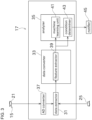
- FIG. 1 is a schematic diagram of a rail-guided cart system 3 according to one embodiment of the present invention.
- FIG. 2 is a diagram showing a traveling rail 9 provided in the rail-guided cart system 3.
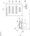
- FIG. 3 is a block diagram showing a configuration of a diagnosis device 17.
- the rail-guided cart system 3 shown in FIG. 1 is, for example, an automated transport system installed in a semiconductor manufacturing plant.
- the rail-guided cart system 3 can transport objects 5 which is to be transported such as FOUPs.
- the FOUP is an abbreviation for Front Opening Unified Pod.
- the rail-guided cart system 3 includes a plurality of traveling carts 7 and a traveling rail (rail) 9.
- the traveling carts 7 are rail-guided carts that travel along the traveling rail 9.
- an overhead transport vehicle called an OHT is used as the traveling carts 7.
- the OHT is an abbreviation for Overhead Hoist Transfer.
- the traveling carts 7 is not limited to this.
- multiple traveling carts 7 with substantially identical configurations travel simultaneously. This allows for more efficient transportation.
- Each traveling cart 7 includes a cart controller 11, as shown in FIG. 1 .
- the cart controller 11 is configured as a known computer including a CPU, a ROM, a RAM, an HDD, and the like.
- the cart controller 11 controls the transfer operation of the to-be-transported object 5 by the transfer mechanism, such as an articulated robot arm or hoist equipped with the traveling cart 7, the automatic traveling by the traveling mechanism (not shown), and the like.
- the traveling cart 7 controlled by the cart controller 11 travels along the traveling rail 9 with an appropriate distance from other traveling carts 7.
- the traveling rail 9 is located in a building 13 of a semiconductor manufacturing plant or the like where the rail-guided cart system 3 is used. Specifically, the traveling rail 9 is provided suspended from a ceiling of the building 13. The traveling rail 9 may be suspended from a trestle installed on a floor. The traveling rail 9 has a shape that can guide the traveling path of the traveling cart 7 shown in FIG. 1 for example. The shape of the traveling rail 9 is not limited.
- the rail-guided cart system 3 is equipped with a learning system 1.
- the learning system 1 includes a measurement device 15, a diagnosis device 17, and a notifier 45.
- the measurement device 15 can measure at least one of vibration and sound generated by the traveling cart 7.
- the measurement device 15 is configured by a sensor (measurement unit) 21.
- the sensor 21 detects the vibration or the sound of the traveling rail 9 when the traveling cart 7 is traveling, and outputs detection signals according to detection results of the sensor 21 to the diagnosis device 17. These detection signals correspond to measurement data measured by the sensor 21.
- the sensor 21 in this embodiment detects the vibration or the sound of the traveling rail 9.
- the sensor 21 is installed on the traveling rail 9 side and not on the traveling cart 7.
- the sensor 21 is fixedly provided with respect to the traveling rail 9.
- the sensor 21 is a vibration sensor that detects vibration
- the sensor can be, for example, an acceleration sensor, an AE (Acoustic Emission) sensor, an ultrasonic sensor, a shock pulse sensor or the like.
- the sensor 21 is a sound sensor that detects sound
- the sensor includes, for example, a microphone or the like.
- a location where the sensor 21 is located is hereinafter referred to as measurement point P1.
- the measurement point P1 is defined at an appropriate location on the traveling rail 9, as shown in FIG. 2 .
- a special area called a diagnosis area, is defined in the vicinity of the measurement point P1.
- the learning system 1 is provided with a position sensor 25.
- the position sensor 25 detects the traveling cart 7 passing through the measurement point P1.
- the position sensor 25 is fixedly provided with respect to the traveling rail 9.
- the position sensor 25 is located near a portion of the traveling rail 9 that corresponds to the measurement point P1.
- the position sensor 25 is configured by a photoelectric sensor including a light emitter/receiver. When the light emitter/receiver detects that the light emitted by itself is reflected by a reflective part of the traveling cart 7, etc., the position sensor 25 outputs a cart detection signal to the diagnosis device 17.
- the configuration of the position sensor 25 is not limited to this.
- the diagnosis device 17 can determine a condition of the traveling cart 7 that passed through the measurement point P1 on the traveling rail 9.
- the diagnosis device 17 is electrically connected to each of the sensor 21 and the position sensor 25.
- the diagnosis device 17 is configured by a known computer including a CPU, a ROM, a RAM, an HDD, and the like.
- the diagnosis device 17 performs various processes (including diagnosis which will be described later) by executing programs stored in a memory configured by the ROM, the RAM, the HDD, and the like.
- the notifier 45 includes a display such as an LCD monitor, a light, a buzzer, or the like.
- the notifier 45 is electrically connected to the diagnosis device 17.
- the notifier 45 notifies the diagnosis result of the condition of the traveling cart 7 made by the diagnosis device 17 to the operator or the like by displaying information and by notifying by sound and/or light. This enables the operator or the like to promptly know the condition of the traveling cart 7.
- the diagnosis device 17 includes an AD converter 37, a data extractor 31, a data converter 33, and an analyzer 35.
- the AD converter 37 converts the analog signal output by the sensor 21 into a digital signal.
- the AD converter 37 outputs the converted digital signal to the data extractor 31.
- the data extractor 31 extracts from the detection signals output by the sensor 21 only a part according to a predetermined time range that includes timing when the vibration or the sound of the traveling rail 9 is generated by the passage of the traveling cart 7. This time range is defined based on timing at which the position sensor 25 outputs the cart detection signal.
- the detection signals thus extracted may be referred to as partial signals (partial data).
- the partial signals may be used for training or diagnosis, depending on the situation. Therefore, the data extractor 31 functions as a for-training partial data extractor and a for-diagnosis partial data extractor.
- the data converter 33 converts the partial signals extracted by the data extractor 31 to acquire a frequency spectrum.
- the data converter 33 includes a feature extractor 39.
- the feature extractor 39 acquires a frequency spectrum contained in the partial signals cut out by the data extractor 31. Specifically, the feature extractor 39 performs a discrete Fourier transform process on the partial signals output by the data extractor 31. As a result, the frequency spectrum representing the partial signals as a relationship between the frequency and the intensity of the signal oscillating at that frequency is acquired. In this embodiment, this frequency spectrum is used as a feature (for-training feature or for-diagnosis feature).
- the analyzer 35 constructs a learning model by machine learning a number of frequency spectra input from data converter 33.
- the learning model is a function that inputs a frequency spectrum and outputs an evaluation value.
- the analyzer 35 uses this learning model to compute the evaluation value, from the frequency spectrum input from data converter 33 for any traveling cart 7. Since this evaluation value is the result of machine learning, it can be called a machine learning evaluation value.
- the evaluation value acquired from the learning model is used to diagnose the condition of the traveling cart 7.
- the analyzer 35 includes a machine learning unit (learning controller) 41 and a condition determiner (diagnosis unit) 43.
- the machine learning unit 41 constructs the learning model for the diagnosis of the condition of the traveling cart 7 using the frequency spectra of the partial signals corresponding to the plurality of traveling carts 7 as a set of training data.
- a one-class SVM which is known is used as the learning model.
- SVM is an abbreviation for Support Vector Machine.
- an outlier detection is performed by unsupervised learning of a one-class SVM.
- FIGS. 4 and 5 show flowcharts of processes in the learning system 1 for the machine learning unit 41 to construct the learning model.
- the learning system 1 collects data for the machine learning unit 41 to construct the learning model by the process shown in FIG. 4 .
- any traveling cart 7 that passes through the measurement point on the traveling rail 9 is a normal traveling cart 7.
- the data acquired by measuring a normal traveling cart 7 may be referred to as normal data.
- the data extractor 31 of the diagnosis device 17 extracts signals partially from the detection signals acquired by the sensor 21 (step S102).
- the partial signals described above are acquired.
- the time range in which the partial signal is cut out from the detection signal is, referring to the timing when the position sensor 25 detects that the traveling cart 7 passes through the measurement point P1, from a predetermined time before the reference timing to a predetermined time after the reference timing.
- the feature extractor 39 executes a discrete Fourier transform process on the partial signals from the data extractor 31 and extracts a frequency spectrum (step S103).
- the feature input to the learning model is this frequency spectrum.
- the feature is the signal strength of each frequency component in the frequency spectrum. Smoothing is performed on the frequency spectrum as appropriate. There are various methods of smoothing, for example, a convolution integral of a Gaussian filter.
- the memory (not shown) of the diagnosis device 17 stores the frequency spectrum acquired by the feature extractor 39 as for-training data that constitutes a for-training data set (step S104).
- step S105 The process from step S101 to step S104 is repeatedly performed until the traveling cart 7 passes through the measurement point P1 enough times and a large number (for example, thousands) of frequency spectra are acquired (step S105).
- a traveling speed at which the traveling cart 7 passes through the measurement point P1 for data collection is controlled to be constant at a predetermined speed for data acquisition.
- the measurement point P1 set on the traveling rail 9 can be passed by not only one but also multiple traveling carts 7.
- it is replaced with a normal traveling cart 7 which is a different device from above (step S 106), the collection process of a similar number of frequency spectra is carried out.
- the for-training data set is essentially a collection of a large number of the frequency spectra.
- This for-training data set is stored in the memory of the diagnosis device 17.
- the for-training data set stored in this memory can be changed (updated) as needed.
- the for-training data set acquired in the process of FIG. 4 includes the frequency spectra obtained from multiple traveling carts 7 (multiple traveling carts 7 different from each other).
- the for-training data set to perform machine learning, it is possible to suppress overtraining in relation to individual features specific to one traveling cart 7.
- the number of traveling carts 7 from which the frequency spectra are collected is arbitrary as long as it is greater than or equal to two, but it is preferable to use a certain large number so that the individual differences among the traveling carts 7 will not be emphasized.
- This for-training data set does not include frequency spectra acquired from abnormal traveling carts 7, and all frequency spectra are acquired from normal traveling carts 7.
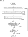
- the learning system 1 uses the acquired for-training data set to perform machine learning by the machine learning unit 41 using the process shown in FIG. 5 .
- the process in FIG. 5 corresponds to a training phase of machine learning.
- the machine learning unit 41 initializes parameters of a determination equation to determine the abnormality of the traveling cart 7 as appropriate (step S201).
- f(x) is the determination equation and corresponds to the learning model of this embodiment.
- the input to the determination equation f i.e., x, is an N-dimensional vector representing the frequency spectrum to be input.
- N means the number of frequency components when the frequency spectrum is expressed in terms of the signal strength of each of the multiple frequency components.
- the output of the determination equation f is a scalar value called the evaluation value, details of which will be described later.
- K(xi, x) is a known kernel function of a one-class SVM.
- the kernel function is a mapping function to a higher-dimensional space such that the output becomes closer to the origin as the frequency spectrum becomes an outlier.
- a hyperplane with the maximum distance from the origin is defined in this mapping to the higher-dimensional space. This hyperplane is a criterion for determining outliers.
- a Gaussian kernel is used as the kernel function, but the kernel function is not limited to this.
- ⁇ i, xi, and ⁇ are the parameters subject to machine learning.
- constructing a learning model corresponds to acquiring the optimal values of ⁇ i, xi, and ⁇ to determine the determination equation.
- these parameters are initialized.
- the values used for initialization can be, for example, random values.
- a parameter other than the above, i.e., ⁇ , is called hyperparameter and is determined as appropriate by the designer.
- the machine learning unit 41 picks up one frequency spectrum contained in the for-training data set, to substitute in the form of an N-dimensional vector x into the determination equation f to acquire the value f(x) (step S202). Then, ⁇ i, xi, and ⁇ are adjusted so that the acquired value f(x) is close to 0 (step S203). The process of step S202 and step S203 is repeated for all frequency spectra of the for-training data set (step S204). In this way, the training is completed for one epoch. The epoch indicates that the for-training data contained in the for-training data set is trained once.
- step S205 The process from step S202 to step S204 is further repeated an appropriate number of times. This results in training for multiple epochs. Training is repeated an appropriate number of times for one for-training data set, therefore, the learning model with good performance can be realized.
- the values of the parameters ⁇ i, xi, and ⁇ are acquired by the process of FIG. 5 and the values of the parameters are stored in the memory of the diagnosis device 17.
- the above-mentioned determination equation f, to which the values of the parameters ⁇ i, xi, and ⁇ are assigned, represents a learned model. Therefore, substantially speaking, the acquired values of the parameters ⁇ i, xi, and ⁇ themselves can be considered to be the learned model.
- condition determiner 43 of this embodiment diagnoses whether the condition of the traveling cart 7 is normal/abnormal, using the fact that the frequency spectrum when an abnormality occurs in the traveling cart 7 is an outlier in relation to the frequency spectrum when it is normal.
- the process shown in FIG. 6 corresponds to an inference phase of machine learning.
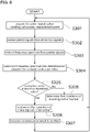
- the vibration or sound caused by traveling of the traveling cart 7 is acquired by the sensor 21 (step S301).
- the traveling cart 7 is controlled to pass through the measurement point P1 at the same speed as the speed for data acquisition described above.
- Partial signals are cut out from these detection signals (step S302).
- this partial signals may be referred to as for-diagnosis partial signals.
- a frequency spectrum is extracted from these for-diagnosis partial signals (step S303).
- step S301 to step S303 is substantially the same as that of step S101 to step S103 in FIG. 4 .
- the condition determiner 43 inputs the frequency spectrum acquired in step S303 into the determination equation and computes an evaluation value (step S304).
- the parameters acquired by the process in FIG. 5 are used as the parameters ⁇ i, xi, and ⁇ of the determination equation. Therefore, the determination equation used in step S304 is synonymous with the trained learning model.
- FIG. 7 is a graph showing changes in the evaluation value when the same traveling cart 7 is kept in operation. This graph can be obtained by having the learning model (determination equation) complete the training phase of FIG. 5 and then actually performing a durability test of the traveling cart 7, etc.
- the threshold value v1 is set to a value at which it is assumed that the traveling cart 7 will soon fail, as shown in the graph in FIG. 7 .
- the threshold value v1 which serves as the boundary for determining between normal and abnormal conditions, is set to a value with some margin for the evaluation value corresponding to a condition in which a clear failure appears in the traveling cart 7 (hereinafter referred to as in-failure evaluation value v2).
- the threshold value v1 and the in-failure evaluation value v2 are negative values.
- the in-failure evaluation value v2 can be defined with reference to the results of the durability test described above.
- the threshold value v1 is larger than the in-failure evaluation value v2 by the margin described above. The size of this margin is defined in consideration of the importance of the continued operation of the rail-guided cart system 3, the cost of replacing parts, etc.
- the condition determiner 43 determines that the condition of the traveling cart 7 is abnormal (step S306). In this case, the condition determiner 43 transmits the determination result (that the condition of the traveling cart 7 is abnormal) to the notifier 45 (step S307). As a result, the notifier 45 notifies, for example, one or both of that "the condition of the traveling cart 7 is abnormal" and that "a traveling cart for replacing or parts need to be prepared for the traveling cart 7".
- the length of remaining uptime is a length of time until the evaluation value is expected to fall below the in-failure evaluation value v2. The length of remaining uptime can be estimated, for example, by the graph in FIG. 7 and the current evaluation value.
- condition determiner 43 determines that the condition of the traveling cart 7 is normal (step S308).
- step S301 Regardless of whether the determination result is normal/abnormal, the process returns to step S301 and the diagnosis is performed again as the traveling cart 7 passes.
- the notification by the notifier 45 preferably includes information that parts of the traveling cart 7 or a traveling cart for replacing will need to be prepared. In this case, the appropriate preparation can be urged to the operator or the like.
- the rail-guided cart system 3 of this embodiment includes the traveling rail 9 and the traveling cart 7 that travels along the traveling rail 9.
- the rail-guided cart system 3 includes the sensor 21 and the diagnosis device 17.
- the sensor 21 is fixedly provided with respect to the traveling rail 9 and measures vibration or sound.
- the diagnosis device 17 diagnoses the condition of the traveling cart 7 that passed through the measurement point P1 on the traveling rail 9 corresponding to the location of the sensor 21, based on the measurement data measured by the sensor 21.
- the rail-guided cart system 3 of this embodiment includes the feature extractor 39 and the machine learning unit 41.
- the feature extractor 39 extracts the frequency spectrum contained in the for-training partial signals which are partial signals corresponding to the detection signals when the traveling cart 7 passes through the measurement point P1, from the detection signals detected by the sensor 21.
- the machine learning unit 41 constructs the learning model for the diagnosis of the condition of the traveling cart 7 by using a for-training data set which is a set of the frequency spectra based on the detection signals measured by the sensor 21 for a plurality of traveling carts 7.
- the rail-guided cart system 3 of this embodiment includes the data extractor 31.
- the data extractor 31 extracts the for-training partial signals from the detection signals detected by the sensor 21.
- the feature extractor 39 extracts the frequency spectrum included in the for-diagnosis partial signals which are partial signals corresponding to the detection signals when the traveling cart 7 passes through the measurement point P1, from the detection signals detected by the sensor 21.
- the diagnosis device 17 computes an evaluation value corresponding to the frequency spectrum extracted by the feature extractor 39 based on the learning model trained by the machine learning unit 41.
- the rail-guided cart system 3 includes the data extractor 31.
- the data extractor 31 extracts the for-diagnosis partial signals from the detection signals detected by the sensor 21.
- the rail-guided cart system 3 of this embodiment includes a position sensor 25.
- the position sensor 25 is fixedly provided with respect to the traveling rail 9 and detects the traveling cart 7 passing through the measurement point P1.
- the data extractor 31 extracts partial signals (for-training partial signals and for-diagnosis partial signals) based on the timing at which the position sensor 25 detects the traveling cart 7.
- the traveling rail 9 is provided suspended from the ceiling of the building 13.
- the traveling cart 7 is the overhead transport vehicle that travels along the traveling rail 9.
- the traveling cart 7 as an overhead transport vehicle can be checked without having to take it down from the traveling rail 9, thus alleviating the complexity of maintenance work.
- the range in which the partial signals are cut out from the detection signals is defined based on the timing at which the position sensor 25 outputs the cart detection signal.
- a discrepancy may occur in the timing at which vibration or sound is generated on the traveling rail 9 when the traveling cart 7 passes through the measurement point P1. This may reduce the accuracy of the discrimination result. Therefore, in this modification, a correction is made to adjust the detection signal to be extracted in the direction of the time axis.
- reference signals that serve as a basis for defining the range of data extracted by the data extractor 31 are stored in the diagnosis device 17 in advance.
- This reference signals can be acquired based on the output of the AD converter 37 when the traveling cart 7 passes through the measurement point P1.
- a traveling cart 7 in normal condition is used as the traveling cart 7 at this time, and the traveling cart 7 passes through the measurement point P1 at the speed for data acquisition described above.
- the graph in FIG. 8 shows an example of the relationship between the waveform of the detection signals acquired in step S101 and the waveform of the reference signals when the sensor 21 is a vibration sensor.
- the detection signals are represented in a simplified form for convenience.
- the data extractor 31 computes a correlation of the acquired detection signals 53 with the reference signals 51 while variously offsetting the detection signals 53 in a time axis direction, and searches for the direction and amount of offset that maximizes the correlation.
- the data extractor 31 offsets the detection signals 53 in the time axis direction so that the correlation of the detection signals 53 to the reference signals 51 is the largest.
- the time range in which the data extractor 31 extracts the detection signals is defined not with respect to the timing at which the position sensor 25 outputs the cart detection signal, but the reference signals.
- the data extractor 31 cuts out the detection signals according to this time range to acquire the partial signals.
- Offsetting of the detection signal is not only performed in the process of FIG. 4 , but also in the process of FIG. 6 .
- the process of eliminating the timing discrepancy of the waveforms acquired by the sensor 21 can improve the accuracy of the diagnosis by the learning model.
- the data extractor 31 determines the correlation between the reference signals 51 and the detection signals 53 to be extracted, while variously offsetting the detection signals 53 in the time axis direction.
- the data extractor 31 cuts out the partial signals from the detection signals 53 according to the time range defined with reference to the reference signals 51, in a state where the detection signals 53 are offset in the time axis direction so that the correlation is the largest.
- the machine learning unit 41 and the condition determiner 43 are provided in one diagnosis device 17, however, they may be provided in different devices.
- the machine learning unit 41 in FIG. 3 can be taken out and made into a different device from the diagnosis device 17.
- the computer with the machine learning unit 41, which is different from the diagnosis device 17, is referred to as training device.
- the location where the learning model is constructed is to be different from the location where the diagnosis of the condition of the traveling cart 7 is performed.
- the for-training data set acquired by the data collection at the diagnosis device 17 is provided to the training device.
- the data of the learning model constructed in the training device (in effect, the parameters of the determination equation described above) are provided to the diagnosis device 17.
- the provision of data between devices can be done, for example, by known communication.
- the condition determiner 43 can determine that the traveling cart 7 is approaching abnormality. The result of this determination can be notified using the notifier 45 in the same way as when the evaluation value becomes less than the threshold value v1.
Landscapes
- Engineering & Computer Science (AREA)
- Mechanical Engineering (AREA)
- Physics & Mathematics (AREA)
- General Physics & Mathematics (AREA)
- Transportation (AREA)
- Measurement Of Mechanical Vibrations Or Ultrasonic Waves (AREA)
- Control Of Position, Course, Altitude, Or Attitude Of Moving Bodies (AREA)
- Machines For Laying And Maintaining Railways (AREA)
- Testing And Monitoring For Control Systems (AREA)
- Testing Of Devices, Machine Parts, Or Other Structures Thereof (AREA)
Abstract
Description
- This invention relates to a configuration for diagnosing a condition of a cart in a rail-guided cart system.
- Conventionally, the condition of a rail-guided cart system has been diagnosed in various ways in order to take into account the possibility of failure. PTL 1 discloses a method for detecting deterioration of a traveling wheel of a traveling cart.
- The traveling cart disclosed by PTL 1 is equipped with a drive wheel unit. The drive wheel unit has a traveling wheel, a reduction gear, a traveling motor, and other components. The traveling motor includes an encoder. This encoder detects a rotation speed of the traveling wheel. The output torque signal and the encoder signal are extracted from the traveling motor, and the slip speed is determined by the difference between the encoder signal and the signal from a linear sensor on the traveling cart. Concerning a space defined by the traveling torque and the slip speed (for example, a two-dimensional plane), based on the fact that the output torque and the slip speed of the traveling motor pass through a predetermined anomaly region, the deterioration of the traveling wheel is detected.
- PTL 1:
Japanese Patent No. 6337528 - However, the technology in PTL 1 above requires an installation of encoders and linear sensors for all of the target overhead traveling vehicles in order to detect the deterioration of the traveling wheels, and there is room for improvement in this respect.
- The present invention is made in view of the circumstances described above, and an object of the present invention is to provide a rail-guided cart system that diagnoses the condition of the rail without installing special sensors on the side of the cart.
- The problem to be solved by the present invention is as described above, and next, means for solving the problem and effects thereof will be described.
- According to an aspect of the present invention, a rail-guided cart system having the following configuration is provided. That is, the rail-guided cart system includes a rail and a cart that travels along the rail. The rail-guided cart system includes a measurement unit and a diagnosis device. The measurement unit is fixedly provided with respect to the rail and measures at least one of vibration and sound. The diagnosis device diagnoses a condition of the cart passing through a measurement point on the rail corresponding to a location of the measurement unit, based on the measurement data measured by the measurement unit.
- This allows the condition of the cart to be diagnosed without the need for a special sensor on the side of the cart. Since the measurement unit does not need to be installed on each of traveling carts, the cost can be reduced.
- The rail-guided cart system described above is preferably configured as follows. That is, the rail-guided cart system includes a feature extractor and a learning controller. The feature extractor extracts a for-training feature contained in for-training partial data which are partial data corresponding to data when the cart passes the measurement point, from measurement data measured by the measurement unit. The learning controller constructs a learning model for diagnosis of the condition of the cart by using a for-training data set which is a set of the for-training features based on measurement data measured by the measurement unit for the plurality of carts.
- This allows for a good learning model to be realized.
- The rail-guided cart system described above is preferably configured as follows. That is, the rail-guided cart system includes a for-training partial data extractor. The for-training partial data extractor extracts the for-training partial data from measurement data measured by the measurement unit.
- This allows the for-training partial data to be acquired successfully.
- The rail-guided cart system described above is preferably configured as follows. That is, the feature extractor extracts a for-diagnosis feature contained in for-diagnosis partial data which are partial data corresponding to data when the cart passes through the measurement point, from measurement data measured by the measurement unit. The diagnosis device computes a machine learning evaluation value corresponding to the for-diagnosis feature extracted by the feature extractor based on the learning model trained by the learning controller.
- This allows for a good diagnosis of the condition of the cart using the machine learning evaluation value.
- The rail-guided cart system described above is preferably configured as follows. That is, the rail-guided cart system includes a for-diagnosis partial data extractor. The for-diagnosis partial data extractor extracts the for-diagnosis partial data from measurement data measured by the measurement unit.
- This enables good acquisition of the for-diagnosis partial data.
- The rail-guided cart system described above is preferably configured as follows. That is, the rail-guided cart system includes a position sensor. The position sensor is fixedly provided with respect to the rail and detects the cart passing through the measurement point. The partial data are extracted from the measurement data based on timing at which the position sensor detects the cart.
- This allows for better acquisition of the partial data.
- The rail-guided cart system described above is preferably configured as follows. That is, a correlation between reference data as a basis and measurement data to be extracted is determined while the measurement data are variously offset in a time axis direction. The partial data are extracted by cutting out from the measurement data in a time range defined with reference to the reference data, with the measurement data offset in the time axis direction so that the correlation is the largest.
- This allows the partial data (for-training partial data and for-diagnosis partial data) to be accurately acquired.
- The rail-guided cart system described above is preferably configured as follows. That is, the rail is provided suspended from a ceiling of a building or from a trestle installed on a floor. The cart is an overhead transport vehicle traveling along the rail.
- Since the overhead transport vehicle is installed at a high location, maintenance work on it is generally difficult. However, according to this configuration, the condition of the overhead transport vehicle can be checked without having to take it down from the rail, thus alleviating the complexity of maintenance work.
-
-
FIG. 1 is a schematic diagram of a rail-guided cart system according to one embodiment of the present invention. -
FIG. 2 is a diagram showing a traveling rail provided by the rail-guided cart system. -
FIG. 3 is a block diagram showing a configuration of a diagnosis device. -
FIG. 4 is a flowchart of a process performed by the rail-guided cart system to acquire a data set for training. -
FIG. 5 is a flowchart of a process of performing machine learning. -
FIG. 6 is a flowchart of a process performed in the rail-guided cart system for a condition determiner to make a determination. -
FIG. 7 is a graph showing a relationship between the operating hours of the traveling cart and an evaluation value. -
FIG. 8 is a graph explaining an offset process of detection signals. - Next, embodiments of the present invention will be described with reference to the drawings.
FIG. 1 is a schematic diagram of a rail-guidedcart system 3 according to one embodiment of the present invention.FIG. 2 is a diagram showing a travelingrail 9 provided in the rail-guidedcart system 3.FIG. 3 is a block diagram showing a configuration of adiagnosis device 17. - The rail-guided
cart system 3 shown inFIG. 1 is, for example, an automated transport system installed in a semiconductor manufacturing plant. The rail-guidedcart system 3 can transportobjects 5 which is to be transported such as FOUPs. The FOUP is an abbreviation for Front Opening Unified Pod. - The rail-guided
cart system 3 includes a plurality of travelingcarts 7 and a traveling rail (rail) 9. - The traveling
carts 7 are rail-guided carts that travel along the travelingrail 9. In this embodiment, an overhead transport vehicle called an OHT is used as the travelingcarts 7. The OHT is an abbreviation for Overhead Hoist Transfer. However, the travelingcarts 7 is not limited to this. In the rail-guidedcart system 3 of this embodiment, multiple travelingcarts 7 with substantially identical configurations travel simultaneously. This allows for more efficient transportation. - Each traveling
cart 7 includes acart controller 11, as shown inFIG. 1 . Thecart controller 11 is configured as a known computer including a CPU, a ROM, a RAM, an HDD, and the like. - The
cart controller 11 controls the transfer operation of the to-be-transported object 5 by the transfer mechanism, such as an articulated robot arm or hoist equipped with the travelingcart 7, the automatic traveling by the traveling mechanism (not shown), and the like. The travelingcart 7 controlled by thecart controller 11 travels along the travelingrail 9 with an appropriate distance from other travelingcarts 7. - As shown in
FIG. 2 , the travelingrail 9 is located in abuilding 13 of a semiconductor manufacturing plant or the like where the rail-guidedcart system 3 is used. Specifically, the travelingrail 9 is provided suspended from a ceiling of thebuilding 13. The travelingrail 9 may be suspended from a trestle installed on a floor. The travelingrail 9 has a shape that can guide the traveling path of the travelingcart 7 shown inFIG. 1 for example. The shape of the travelingrail 9 is not limited. - The rail-guided
cart system 3 is equipped with a learning system 1. As shown inFIG. 1 , the learning system 1 includes ameasurement device 15, adiagnosis device 17, and anotifier 45. - The
measurement device 15 can measure at least one of vibration and sound generated by the travelingcart 7. In this embodiment, themeasurement device 15 is configured by a sensor (measurement unit) 21. Thesensor 21 detects the vibration or the sound of the travelingrail 9 when the travelingcart 7 is traveling, and outputs detection signals according to detection results of thesensor 21 to thediagnosis device 17. These detection signals correspond to measurement data measured by thesensor 21. - As mentioned above, the
sensor 21 in this embodiment detects the vibration or the sound of the travelingrail 9. In this embodiment, thesensor 21 is installed on the travelingrail 9 side and not on the travelingcart 7. In other words, thesensor 21 is fixedly provided with respect to the travelingrail 9. When thesensor 21 is a vibration sensor that detects vibration, the sensor can be, for example, an acceleration sensor, an AE (Acoustic Emission) sensor, an ultrasonic sensor, a shock pulse sensor or the like. When thesensor 21 is a sound sensor that detects sound, the sensor includes, for example, a microphone or the like. A location where thesensor 21 is located is hereinafter referred to as measurement point P1. The measurement point P1 is defined at an appropriate location on the travelingrail 9, as shown inFIG. 2 . Although not shown, a special area, called a diagnosis area, is defined in the vicinity of the measurement point P1. - The learning system 1 is provided with a
position sensor 25. Theposition sensor 25 detects the travelingcart 7 passing through the measurement point P1. Theposition sensor 25 is fixedly provided with respect to the travelingrail 9. - The
position sensor 25 is located near a portion of the travelingrail 9 that corresponds to the measurement point P1. Theposition sensor 25 is configured by a photoelectric sensor including a light emitter/receiver. When the light emitter/receiver detects that the light emitted by itself is reflected by a reflective part of the travelingcart 7, etc., theposition sensor 25 outputs a cart detection signal to thediagnosis device 17. However, the configuration of theposition sensor 25 is not limited to this. - Based on the detection signals detected by the
sensor 21, thediagnosis device 17 can determine a condition of the travelingcart 7 that passed through the measurement point P1 on the travelingrail 9. Thediagnosis device 17 is electrically connected to each of thesensor 21 and theposition sensor 25. - The
diagnosis device 17 is configured by a known computer including a CPU, a ROM, a RAM, an HDD, and the like. Thediagnosis device 17 performs various processes (including diagnosis which will be described later) by executing programs stored in a memory configured by the ROM, the RAM, the HDD, and the like. - The
notifier 45 includes a display such as an LCD monitor, a light, a buzzer, or the like. Thenotifier 45 is electrically connected to thediagnosis device 17. Thenotifier 45 notifies the diagnosis result of the condition of the travelingcart 7 made by thediagnosis device 17 to the operator or the like by displaying information and by notifying by sound and/or light. This enables the operator or the like to promptly know the condition of the travelingcart 7. - As shown in
FIGS. 1 and3 , thediagnosis device 17 includes anAD converter 37, adata extractor 31, adata converter 33, and ananalyzer 35. - The
AD converter 37 converts the analog signal output by thesensor 21 into a digital signal. TheAD converter 37 outputs the converted digital signal to thedata extractor 31. - The
data extractor 31 extracts from the detection signals output by thesensor 21 only a part according to a predetermined time range that includes timing when the vibration or the sound of the travelingrail 9 is generated by the passage of the travelingcart 7. This time range is defined based on timing at which theposition sensor 25 outputs the cart detection signal. Hereafter, the detection signals thus extracted may be referred to as partial signals (partial data). The partial signals may be used for training or diagnosis, depending on the situation. Therefore, thedata extractor 31 functions as a for-training partial data extractor and a for-diagnosis partial data extractor. - The
data converter 33 converts the partial signals extracted by thedata extractor 31 to acquire a frequency spectrum. Thedata converter 33 includes afeature extractor 39. - The
feature extractor 39 acquires a frequency spectrum contained in the partial signals cut out by thedata extractor 31. Specifically, thefeature extractor 39 performs a discrete Fourier transform process on the partial signals output by thedata extractor 31. As a result, the frequency spectrum representing the partial signals as a relationship between the frequency and the intensity of the signal oscillating at that frequency is acquired. In this embodiment, this frequency spectrum is used as a feature (for-training feature or for-diagnosis feature). - The
analyzer 35 constructs a learning model by machine learning a number of frequency spectra input fromdata converter 33. In this embodiment, the learning model is a function that inputs a frequency spectrum and outputs an evaluation value. Once the learning model is constructed, theanalyzer 35 uses this learning model to compute the evaluation value, from the frequency spectrum input fromdata converter 33 for any travelingcart 7. Since this evaluation value is the result of machine learning, it can be called a machine learning evaluation value. The evaluation value acquired from the learning model is used to diagnose the condition of the travelingcart 7. - The
analyzer 35 includes a machine learning unit (learning controller) 41 and a condition determiner (diagnosis unit) 43. - The
machine learning unit 41 constructs the learning model for the diagnosis of the condition of the travelingcart 7 using the frequency spectra of the partial signals corresponding to the plurality of travelingcarts 7 as a set of training data. In this embodiment, a one-class SVM which is known is used as the learning model. SVM is an abbreviation for Support Vector Machine. In this embodiment, an outlier detection (in other words, anomaly detection) is performed by unsupervised learning of a one-class SVM. - The construction of the learning model will be described below in detail.
FIGS. 4 and5 show flowcharts of processes in the learning system 1 for themachine learning unit 41 to construct the learning model. - First, the learning system 1 collects data for the
machine learning unit 41 to construct the learning model by the process shown inFIG. 4 . - First, for a traveling
cart 7 traveling along the travelingrail 9, detection signals about vibration or sound caused by traveling are acquired by the sensor 21 (step S101). Here, any travelingcart 7 that passes through the measurement point on the travelingrail 9 is anormal traveling cart 7. Hereafter, the data acquired by measuring anormal traveling cart 7 may be referred to as normal data. - Next, the
data extractor 31 of thediagnosis device 17 extracts signals partially from the detection signals acquired by the sensor 21 (step S102). Thus, the partial signals described above are acquired. The time range in which the partial signal is cut out from the detection signal is, referring to the timing when theposition sensor 25 detects that the travelingcart 7 passes through the measurement point P1, from a predetermined time before the reference timing to a predetermined time after the reference timing. - Next, in the
data converter 33 of thediagnosis device 17, thefeature extractor 39 executes a discrete Fourier transform process on the partial signals from thedata extractor 31 and extracts a frequency spectrum (step S103). In this embodiment, the feature input to the learning model is this frequency spectrum. Strictly speaking, the feature is the signal strength of each frequency component in the frequency spectrum. Smoothing is performed on the frequency spectrum as appropriate. There are various methods of smoothing, for example, a convolution integral of a Gaussian filter. - Next, the memory (not shown) of the
diagnosis device 17 stores the frequency spectrum acquired by thefeature extractor 39 as for-training data that constitutes a for-training data set (step S104). - The process from step S101 to step S104 is repeatedly performed until the traveling
cart 7 passes through the measurement point P1 enough times and a large number (for example, thousands) of frequency spectra are acquired (step S105). In order to acquire frequency spectra under identical conditions, a traveling speed at which the travelingcart 7 passes through the measurement point P1 for data collection is controlled to be constant at a predetermined speed for data acquisition. - The measurement point P1 set on the traveling
rail 9 can be passed by not only one but also multiple travelingcarts 7. In this embodiment, for example, when about several hundred frequency spectra have been acquired per onenormal traveling cart 7, it is replaced with anormal traveling cart 7 which is a different device from above (step S 106), the collection process of a similar number of frequency spectra is carried out. - The above process results in the for-training data set. In this embodiment, the for-training data set is essentially a collection of a large number of the frequency spectra. This for-training data set is stored in the memory of the
diagnosis device 17. The for-training data set stored in this memory can be changed (updated) as needed. - Because of the cart changeover operation in step S106, the for-training data set acquired in the process of
FIG. 4 includes the frequency spectra obtained from multiple traveling carts 7 (multiple travelingcarts 7 different from each other). By using such a for-training data set to perform machine learning, it is possible to suppress overtraining in relation to individual features specific to one travelingcart 7. The number of travelingcarts 7 from which the frequency spectra are collected is arbitrary as long as it is greater than or equal to two, but it is preferable to use a certain large number so that the individual differences among the travelingcarts 7 will not be emphasized. - This for-training data set does not include frequency spectra acquired from abnormal traveling
carts 7, and all frequency spectra are acquired fromnormal traveling carts 7. - The learning system 1 then uses the acquired for-training data set to perform machine learning by the
machine learning unit 41 using the process shown inFIG. 5 . The process inFIG. 5 corresponds to a training phase of machine learning. - First, in the
analyzer 35 of thediagnosis device 17, themachine learning unit 41 initializes parameters of a determination equation to determine the abnormality of the travelingcart 7 as appropriate (step S201). In this embodiment, the determination equation is expressed as follows.

- In the above formula, f(x) is the determination equation and corresponds to the learning model of this embodiment. The input to the determination equation f, i.e., x, is an N-dimensional vector representing the frequency spectrum to be input. In this embodiment, N means the number of frequency components when the frequency spectrum is expressed in terms of the signal strength of each of the multiple frequency components. The output of the determination equation f is a scalar value called the evaluation value, details of which will be described later.
- K(xi, x) is a known kernel function of a one-class SVM. The kernel function is a mapping function to a higher-dimensional space such that the output becomes closer to the origin as the frequency spectrum becomes an outlier. In a one-class SVM, a hyperplane with the maximum distance from the origin is defined in this mapping to the higher-dimensional space. This hyperplane is a criterion for determining outliers. In this embodiment, a Gaussian kernel is used as the kernel function, but the kernel function is not limited to this.
- αi, xi, and ρ are the parameters subject to machine learning. In this embodiment, constructing a learning model corresponds to acquiring the optimal values of αi, xi, and ρ to determine the determination equation. In step S201, these parameters are initialized. The values used for initialization (initial values of the parameters) can be, for example, random values. A parameter other than the above, i.e., σ, is called hyperparameter and is determined as appropriate by the designer.
- Next, the
machine learning unit 41 picks up one frequency spectrum contained in the for-training data set, to substitute in the form of an N-dimensional vector x into the determination equation f to acquire the value f(x) (step S202). Then, αi, xi, and ρ are adjusted so that the acquired value f(x) is close to 0 (step S203). The process of step S202 and step S203 is repeated for all frequency spectra of the for-training data set (step S204). In this way, the training is completed for one epoch. The epoch indicates that the for-training data contained in the for-training data set is trained once. - The process from step S202 to step S204 is further repeated an appropriate number of times (step S205). This results in training for multiple epochs. Training is repeated an appropriate number of times for one for-training data set, therefore, the learning model with good performance can be realized.
- The values of the parameters αi, xi, and ρ are acquired by the process of
FIG. 5 and the values of the parameters are stored in the memory of thediagnosis device 17. The above-mentioned determination equation f, to which the values of the parameters αi, xi, and ρ are assigned, represents a learned model. Therefore, substantially speaking, the acquired values of the parameters αi, xi, and ρ themselves can be considered to be the learned model. - In outlier detection using the one-class SVM, if the value of f(x) is 0 or positive, it means that x is not an outlier. If the value of f(x) is negative, it means that x is an outlier, and the smaller the value of f(x), the greater the degree of value outlier. The
condition determiner 43 of this embodiment diagnoses whether the condition of the travelingcart 7 is normal/abnormal, using the fact that the frequency spectrum when an abnormality occurs in the travelingcart 7 is an outlier in relation to the frequency spectrum when it is normal. - In the actual diagnosis, the process shown in
FIG. 6 is performed. The process inFIG. 6 corresponds to an inference phase of machine learning. - First, the vibration or sound caused by traveling of the traveling
cart 7 is acquired by the sensor 21 (step S301). At this time, the travelingcart 7 is controlled to pass through the measurement point P1 at the same speed as the speed for data acquisition described above. Partial signals are cut out from these detection signals (step S302). Hereafter, this partial signals may be referred to as for-diagnosis partial signals. Furthermore, a frequency spectrum is extracted from these for-diagnosis partial signals (step S303). - The process of step S301 to step S303 is substantially the same as that of step S101 to step S103 in
FIG. 4 . However, in the case ofFIG. 6 , it is not known whether or not the travelingcart 7 passing through the measurement point P1 has an abnormality. - Next, the
condition determiner 43 inputs the frequency spectrum acquired in step S303 into the determination equation and computes an evaluation value (step S304). At this time, the parameters acquired by the process inFIG. 5 are used as the parameters αi, xi, and ρ of the determination equation. Therefore, the determination equation used in step S304 is synonymous with the trained learning model. - Next, the
condition determiner 43 determines whether the computed evaluation value is less than a threshold value v1 (step S305).FIG. 7 is a graph showing changes in the evaluation value when the same travelingcart 7 is kept in operation. This graph can be obtained by having the learning model (determination equation) complete the training phase ofFIG. 5 and then actually performing a durability test of the travelingcart 7, etc. - In this embodiment, the threshold value v1 is set to a value at which it is assumed that the traveling
cart 7 will soon fail, as shown in the graph inFIG. 7 . - Specifically, the graph in
FIG. 7 shows that the travelingcart 7 will fail and become inoperable at timing of t2. In this case, it is preferable to generate some warning at, for example, timing of t1 which is a little before t2. Therefore, the threshold value v1, which serves as the boundary for determining between normal and abnormal conditions, is set to a value with some margin for the evaluation value corresponding to a condition in which a clear failure appears in the traveling cart 7 (hereinafter referred to as in-failure evaluation value v2). The threshold value v1 and the in-failure evaluation value v2 are negative values. The in-failure evaluation value v2 can be defined with reference to the results of the durability test described above. The threshold value v1 is larger than the in-failure evaluation value v2 by the margin described above. The size of this margin is defined in consideration of the importance of the continued operation of the rail-guidedcart system 3, the cost of replacing parts, etc. - If the evaluation value is less than or equal to the threshold value v1 in the determination of step S305, the
condition determiner 43 determines that the condition of the travelingcart 7 is abnormal (step S306). In this case, thecondition determiner 43 transmits the determination result (that the condition of the travelingcart 7 is abnormal) to the notifier 45 (step S307). As a result, thenotifier 45 notifies, for example, one or both of that "the condition of the travelingcart 7 is abnormal" and that "a traveling cart for replacing or parts need to be prepared for the travelingcart 7". The length of remaining uptime is a length of time until the evaluation value is expected to fall below the in-failure evaluation value v2. The length of remaining uptime can be estimated, for example, by the graph inFIG. 7 and the current evaluation value. - If the evaluation value is greater than or equal to the threshold value v1 in the determination of step S305, the
condition determiner 43 determines that the condition of the travelingcart 7 is normal (step S308). - Regardless of whether the determination result is normal/abnormal, the process returns to step S301 and the diagnosis is performed again as the traveling
cart 7 passes. - The notification by the
notifier 45 preferably includes information that parts of the travelingcart 7 or a traveling cart for replacing will need to be prepared. In this case, the appropriate preparation can be urged to the operator or the like. - As explained above, the rail-guided
cart system 3 of this embodiment includes the travelingrail 9 and the travelingcart 7 that travels along the travelingrail 9. The rail-guidedcart system 3 includes thesensor 21 and thediagnosis device 17. Thesensor 21 is fixedly provided with respect to the travelingrail 9 and measures vibration or sound. Thediagnosis device 17 diagnoses the condition of the travelingcart 7 that passed through the measurement point P1 on the travelingrail 9 corresponding to the location of thesensor 21, based on the measurement data measured by thesensor 21. - This allows the condition of the traveling
cart 7 to be diagnosed without the need for a special sensor on the side of the travelingcart 7. Since thesensor 21 does not need to be installed on each of travelingcarts 7, the cost can be reduced. - The rail-guided
cart system 3 of this embodiment includes thefeature extractor 39 and themachine learning unit 41. Thefeature extractor 39 extracts the frequency spectrum contained in the for-training partial signals which are partial signals corresponding to the detection signals when the travelingcart 7 passes through the measurement point P1, from the detection signals detected by thesensor 21. Themachine learning unit 41 constructs the learning model for the diagnosis of the condition of the travelingcart 7 by using a for-training data set which is a set of the frequency spectra based on the detection signals measured by thesensor 21 for a plurality of travelingcarts 7. - This allows for a good learning model to be realized.
- The rail-guided
cart system 3 of this embodiment includes thedata extractor 31. Thedata extractor 31 extracts the for-training partial signals from the detection signals detected by thesensor 21. - This allows the for-training partial signals to be acquired successfully.
- In the rail-guided
cart system 3 of this embodiment, thefeature extractor 39 extracts the frequency spectrum included in the for-diagnosis partial signals which are partial signals corresponding to the detection signals when the travelingcart 7 passes through the measurement point P1, from the detection signals detected by thesensor 21. Thediagnosis device 17 computes an evaluation value corresponding to the frequency spectrum extracted by thefeature extractor 39 based on the learning model trained by themachine learning unit 41. - This allows for a good diagnosis of the condition of the traveling
cart 7 using the evaluation value. - The rail-guided
cart system 3 includes thedata extractor 31. Thedata extractor 31 extracts the for-diagnosis partial signals from the detection signals detected by thesensor 21. - This allows for good acquisition of the for-diagnosis partial signals.
- The rail-guided
cart system 3 of this embodiment includes aposition sensor 25. Theposition sensor 25 is fixedly provided with respect to the travelingrail 9 and detects the travelingcart 7 passing through the measurement point P1. Thedata extractor 31 extracts partial signals (for-training partial signals and for-diagnosis partial signals) based on the timing at which theposition sensor 25 detects the travelingcart 7. - This allows for better acquisition of the partial signals.
- In the rail-guided
cart system 3 of this embodiment, the travelingrail 9 is provided suspended from the ceiling of thebuilding 13. The travelingcart 7 is the overhead transport vehicle that travels along the travelingrail 9. - Since the overhead transport vehicle is installed at a high location, maintenance work on it is generally complicated. However, according to this embodiment, the condition of the traveling
cart 7 as an overhead transport vehicle can be checked without having to take it down from the travelingrail 9, thus alleviating the complexity of maintenance work. - Next, a modification regarding extraction by the
data extractor 31 will be described. - In the above embodiment, the range in which the partial signals are cut out from the detection signals is defined based on the timing at which the
position sensor 25 outputs the cart detection signal. However, in this configuration, due to individual differences in the mounting positions of the wheels of the travelingcart 7 for example, a discrepancy may occur in the timing at which vibration or sound is generated on the travelingrail 9 when the travelingcart 7 passes through the measurement point P1. This may reduce the accuracy of the discrimination result. Therefore, in this modification, a correction is made to adjust the detection signal to be extracted in the direction of the time axis. - In the learning system 1 of the modification, before collecting data for the for-training data set, reference signals (reference data) that serve as a basis for defining the range of data extracted by the
data extractor 31 are stored in thediagnosis device 17 in advance. This reference signals can be acquired based on the output of theAD converter 37 when the travelingcart 7 passes through the measurement point P1. A travelingcart 7 in normal condition is used as the travelingcart 7 at this time, and the travelingcart 7 passes through the measurement point P1 at the speed for data acquisition described above. - Then, the process of
FIG. 4 starts. The graph inFIG. 8 shows an example of the relationship between the waveform of the detection signals acquired in step S101 and the waveform of the reference signals when thesensor 21 is a vibration sensor. InFIG. 8 , the detection signals are represented in a simplified form for convenience. Thedata extractor 31 computes a correlation of the acquired detection signals 53 with the reference signals 51 while variously offsetting the detection signals 53 in a time axis direction, and searches for the direction and amount of offset that maximizes the correlation. Thedata extractor 31 offsets the detection signals 53 in the time axis direction so that the correlation of the detection signals 53 to the reference signals 51 is the largest. - In this modification, the time range in which the
data extractor 31 extracts the detection signals is defined not with respect to the timing at which theposition sensor 25 outputs the cart detection signal, but the reference signals. Thedata extractor 31 cuts out the detection signals according to this time range to acquire the partial signals. - Offsetting of the detection signal is not only performed in the process of
FIG. 4 , but also in the process ofFIG. 6 . In this modification, the process of eliminating the timing discrepancy of the waveforms acquired by thesensor 21 can improve the accuracy of the diagnosis by the learning model. - As described above, in the rail-guided
cart system 3 of this modification, thedata extractor 31 determines the correlation between the reference signals 51 and the detection signals 53 to be extracted, while variously offsetting the detection signals 53 in the time axis direction. Thedata extractor 31 cuts out the partial signals from the detection signals 53 according to the time range defined with reference to the reference signals 51, in a state where the detection signals 53 are offset in the time axis direction so that the correlation is the largest. - This allows the partial signals to be acquired in a manner that eliminates timing discrepancies.
- While some preferred embodiments of the present invention have been described above, the foregoing configurations may be modified, for example, as follows.
- In the above embodiment, the
machine learning unit 41 and thecondition determiner 43 are provided in onediagnosis device 17, however, they may be provided in different devices. For example, only themachine learning unit 41 inFIG. 3 can be taken out and made into a different device from thediagnosis device 17. Hereafter, the computer with themachine learning unit 41, which is different from thediagnosis device 17, is referred to as training device. In this example, the location where the learning model is constructed is to be different from the location where the diagnosis of the condition of the travelingcart 7 is performed. The for-training data set acquired by the data collection at thediagnosis device 17 is provided to the training device. The data of the learning model constructed in the training device (in effect, the parameters of the determination equation described above) are provided to thediagnosis device 17. The provision of data between devices can be done, for example, by known communication. - When the evaluation value continues to have a large decrease per unit of time (for example, at timing of t3 in
FIG. 7 ), thecondition determiner 43 can determine that the travelingcart 7 is approaching abnormality. The result of this determination can be notified using thenotifier 45 in the same way as when the evaluation value becomes less than the threshold value v1. - In view of the above teachings, it is clear that the present invention can take many modified and variant forms. Accordingly, it is to be understood that the invention may be implemented in ways other than those described herein within the scope of the appended claims.
-
- 3
- Rail-guided cart system
- 7
- Traveling cart (cart)
- 9
- Traveling rail (rail)
- 13
- Building
- 17
- Diagnostic device
- 21
- Sensor (measurement unit)
- 25
- Position sensor
- 31
- Data extractor (for-training partial data extractor, for-diagnosis partial data extractor)
- 39
- Feature extractor
- 41
- Machine learning unit (learning controller)
- 51
- Reference signals (reference data)
- 53
- Detection signals (measurement data)
Claims (8)
- A rail-guided cart system including a rail and a cart that travels along the rail, the rail-guided cart system comprising:a measurement unit fixedly provided with respect to the rail and measures at least one of vibration and sound; anda diagnosis device that diagnoses a condition of the cart passing through a measurement point on the rail corresponding to a location of the measurement unit, based on measurement data measured by the measurement unit.
- The rail-guided cart system according to claim 1, comprising:a feature extractor for extracting a for-training feature contained in for-training partial data which are partial data corresponding to data when the cart passes through the measurement point, from measurement data measured by the measurement unit; anda learning controller that constructs a learning model for diagnosis of the condition of the cart by using a for-training data set which is a set of the for-training features based on measurement data measured by the measurement unit for a plurality of carts.
- The rail-guided cart system according to claim 2, comprising
a for-training partial data extractor that extracts the for-training partial data from measurement data measured by the measurement unit. - The rail-guided cart system according to claim 2 or 3, whereinthe feature extractor extracts a for-diagnosis feature contained in for-diagnosis partial data which are partial data corresponding to data when the cart passes through the measurement point, from measurement data measured by the measurement unit, andthe diagnosis device computes a machine learning evaluation value corresponding to the for-diagnosis feature extracted by the feature extractor based on the learning model trained by the learning controller.
- The rail-guided cart system according to claim 4, comprising
a for-diagnosis partial data extractor that extracts the for-diagnosis partial data from measurement data measured by the measurement unit. - The rail-guided cart system according to claim 3 or 5, comprisinga position sensor that is fixedly provided with respect to the rail and detects the cart passing through the measurement point, whereinthe partial data are extracted from the measurement data based on timing at which the position sensor detects the cart.
- The rail-guided cart system according to claim 3 or 5, whereina correlation between reference data as a basis and measurement data to be extracted is determined while the measurement data are variously offset in a time axis direction, andthe partial data are extracted by cutting out from the measurement data according to a time range defined with reference to the reference data, in a state where the measurement data are offset in the time axis direction so that the correlation is the largest.
- The rail-guided cart system of any one of claims 1 to 7, whereinthe rail is provided suspended from a ceiling of a building or from a trestle installed on a floor, andthe cart is an overhead transport vehicle traveling along the rail.
Applications Claiming Priority (2)
| Application Number | Priority Date | Filing Date | Title |
|---|---|---|---|
| JP2020083557A JP7449489B2 (en) | 2020-05-12 | 2020-05-12 | Track guided trolley system |
| PCT/JP2021/014100 WO2021229948A1 (en) | 2020-05-12 | 2021-03-31 | Rail-guided carrier system |
Publications (2)
| Publication Number | Publication Date |
|---|---|
| EP4151491A1 true EP4151491A1 (en) | 2023-03-22 |
| EP4151491A4 EP4151491A4 (en) | 2024-05-29 |
Family
ID=78510318
Family Applications (1)
| Application Number | Title | Priority Date | Filing Date |
|---|---|---|---|
| EP21804596.1A Pending EP4151491A4 (en) | 2020-05-12 | 2021-03-31 | RAIL-GUIDED CARRIER SYSTEM |
Country Status (6)
| Country | Link |
|---|---|
| US (1) | US12330697B2 (en) |
| EP (1) | EP4151491A4 (en) |
| JP (2) | JP7449489B2 (en) |
| CN (1) | CN115461263B (en) |
| TW (1) | TWI861397B (en) |
| WO (1) | WO2021229948A1 (en) |
Families Citing this family (3)
| Publication number | Priority date | Publication date | Assignee | Title |
|---|---|---|---|---|
| JP7449489B2 (en) * | 2020-05-12 | 2024-03-14 | 村田機械株式会社 | Track guided trolley system |
| JP7646591B2 (en) | 2022-03-15 | 2025-03-17 | 株式会社東芝 | Condition monitoring device, method and program |
| WO2025134537A1 (en) * | 2023-12-21 | 2025-06-26 | 村田機械株式会社 | Traveling vehicle system |
Family Cites Families (14)
| Publication number | Priority date | Publication date | Assignee | Title |
|---|---|---|---|---|
| US7213789B1 (en) * | 2003-04-29 | 2007-05-08 | Eugene Matzan | System for detection of defects in railroad car wheels |
| JP4088973B2 (en) * | 2004-01-22 | 2008-05-21 | 村田機械株式会社 | Overhead traveling car |
| JP2006315813A (en) | 2005-05-13 | 2006-11-24 | Murata Mach Ltd | Mobile diagnostic system |
| JP2008039708A (en) * | 2006-08-10 | 2008-02-21 | Keisuke Ueno | Method and apparatus for diagnosing deterioration of wheel in mobile unit |
| JP6337528B2 (en) | 2014-03-10 | 2018-06-06 | 村田機械株式会社 | Deterioration detection method and detection system for traveling wheel, and traveling carriage |
| JP6557110B2 (en) | 2015-10-13 | 2019-08-07 | 公益財団法人鉄道総合技術研究所 | Condition diagnosis apparatus and program |
| CN105258785B (en) | 2015-10-20 | 2018-02-16 | 中国电子科技集团公司第三研究所 | Acoustic monitoring station, wheel detection method and the passive acoustics diagnostic system of train bearing failure |
| JP6588814B2 (en) * | 2015-12-17 | 2019-10-09 | 株式会社東芝 | Abnormality diagnosis apparatus and method |
| US11476141B2 (en) * | 2016-08-26 | 2022-10-18 | Murata Machinery, Ltd. | Rail-guided trolley system, and rail-guided trolley |
| RU2715064C1 (en) | 2017-01-17 | 2020-02-25 | Сименс Мобилити Гмбх | Method for determining wheel parameter of an observed rail vehicle and an evaluation unit |
| WO2020255206A1 (en) * | 2019-06-17 | 2020-12-24 | 三菱電機株式会社 | Drive noise diagnosis system and drive noise diagnosis method |
| CN113950615B (en) * | 2019-06-17 | 2024-12-03 | 三菱电机株式会社 | Driving sound diagnosis system, driving sound diagnosis method, machine learning device, storage medium and storage device of driving sound diagnosis system |
| JP6689479B1 (en) | 2019-10-23 | 2020-04-28 | 三菱電機株式会社 | Diagnostic system and method |
| JP7449489B2 (en) * | 2020-05-12 | 2024-03-14 | 村田機械株式会社 | Track guided trolley system |
-
2020
- 2020-05-12 JP JP2020083557A patent/JP7449489B2/en active Active
-
2021
- 2021-03-31 US US17/924,705 patent/US12330697B2/en active Active
- 2021-03-31 EP EP21804596.1A patent/EP4151491A4/en active Pending
- 2021-03-31 WO PCT/JP2021/014100 patent/WO2021229948A1/en not_active Ceased
- 2021-03-31 CN CN202180028485.3A patent/CN115461263B/en active Active
- 2021-05-11 TW TW110116878A patent/TWI861397B/en active
-
2024
- 2024-01-31 JP JP2024013320A patent/JP7587768B2/en active Active
Also Published As
| Publication number | Publication date |
|---|---|
| US20230182788A1 (en) | 2023-06-15 |
| CN115461263B (en) | 2025-07-22 |
| US12330697B2 (en) | 2025-06-17 |
| WO2021229948A1 (en) | 2021-11-18 |
| EP4151491A4 (en) | 2024-05-29 |
| CN115461263A (en) | 2022-12-09 |
| TW202210338A (en) | 2022-03-16 |
| JP7449489B2 (en) | 2024-03-14 |
| JP2021178530A (en) | 2021-11-18 |
| JP7587768B2 (en) | 2024-11-21 |
| JP2024032924A (en) | 2024-03-12 |
| TWI861397B (en) | 2024-11-11 |
Similar Documents
| Publication | Publication Date | Title |
|---|---|---|
| JP7587768B2 (en) | Rail-guided vehicle system | |
| US20120330499A1 (en) | Acoustic diagnostic of fielded turbine engines | |
| EP3085937B1 (en) | System and method for detecting vehicle system faults | |
| US10360737B2 (en) | System and method for improved drive system diagnostics | |
| KR102545672B1 (en) | Method and apparatus for machine fault diagnosis | |
| EP2998894A1 (en) | Intelligent condition monitoring and fault diagnostic system | |
| KR20190083029A (en) | System and method of diagnosing defect of components of railway vehicle | |
| CN114391093A (en) | Abnormality determination device and abnormality determination method | |
| US20220153141A1 (en) | Method for ascertaining a state of an electric drive of a means of transportation | |
| CN116383754A (en) | A system and method for on-line monitoring of locomotive and vehicle parts production | |
| CN117957158A (en) | Method for detecting damage to a transport system and control device thereof | |
| CN119283891A (en) | Vehicle fault detection method, device and vehicle | |
| US12405137B2 (en) | Information processing system, information processing method, recording medium, node device, gateway device, manufacturing system, method of manufacturing product | |
| JP4188890B2 (en) | Elevator system diagnostic method and elevator system diagnostic apparatus | |
| US20190066405A1 (en) | Method and system for detecting a road impact event and for diagnosing abnormalities in chassis components | |
| KR102954608B1 (en) | Machine performance diagnostic device | |
| WO2021229947A1 (en) | Learning system | |
| EP4332706A1 (en) | Diagnosis system | |
| US20210114468A1 (en) | Data recording apparatus and data recording method | |
| EP4357740A1 (en) | Acoustic circuit breaker diagnosis device and method | |
| CN114450647B (en) | Diagnostics of technical systems | |
| CN119691632B (en) | A bearing fault diagnosis method and system based on data analysis | |
| Series | On the Detection of Incipient Faults in Rotating Machinery Under Different Operating Speeds Using Unsupervised | |
| JP6487269B2 (en) | Current collector monitoring system | |
| CN121404929A (en) | Methods for detecting escalator anomalies and their application in escalator maintenance early warning |
Legal Events
| Date | Code | Title | Description |
|---|---|---|---|
| STAA | Information on the status of an ep patent application or granted ep patent |
Free format text: STATUS: THE INTERNATIONAL PUBLICATION HAS BEEN MADE |
|
| PUAI | Public reference made under article 153(3) epc to a published international application that has entered the european phase |
Free format text: ORIGINAL CODE: 0009012 |
|
| STAA | Information on the status of an ep patent application or granted ep patent |
Free format text: STATUS: REQUEST FOR EXAMINATION WAS MADE |
|
| 17P | Request for examination filed |
Effective date: 20221207 |
|
| AK | Designated contracting states |
Kind code of ref document: A1 Designated state(s): AL AT BE BG CH CY CZ DE DK EE ES FI FR GB GR HR HU IE IS IT LI LT LU LV MC MK MT NL NO PL PT RO RS SE SI SK SM TR |
|
| DAV | Request for validation of the european patent (deleted) | ||
| DAX | Request for extension of the european patent (deleted) | ||
| A4 | Supplementary search report drawn up and despatched |
Effective date: 20240429 |
|
| RIC1 | Information provided on ipc code assigned before grant |
Ipc: H01L 21/67 20060101ALI20240423BHEP Ipc: H01L 21/677 20060101ALI20240423BHEP Ipc: G01H 1/00 20060101ALI20240423BHEP Ipc: G01H 3/08 20060101ALI20240423BHEP Ipc: B61K 9/12 20060101ALI20240423BHEP Ipc: B61B 3/02 20060101AFI20240423BHEP |
|
| STAA | Information on the status of an ep patent application or granted ep patent |
Free format text: STATUS: EXAMINATION IS IN PROGRESS |
|
| 17Q | First examination report despatched |
Effective date: 20260219 |