EP4151476A1 - Bypass energy accumulating device for electronically controlled hydraulic braking system and control method thereof - Google Patents
Bypass energy accumulating device for electronically controlled hydraulic braking system and control method thereof Download PDFInfo
- Publication number
- EP4151476A1 EP4151476A1 EP21852973.3A EP21852973A EP4151476A1 EP 4151476 A1 EP4151476 A1 EP 4151476A1 EP 21852973 A EP21852973 A EP 21852973A EP 4151476 A1 EP4151476 A1 EP 4151476A1
- Authority
- EP
- European Patent Office
- Prior art keywords
- branch
- pipeline
- braking
- electronically controlled
- controlled hydraulic
- Prior art date
- Legal status (The legal status is an assumption and is not a legal conclusion. Google has not performed a legal analysis and makes no representation as to the accuracy of the status listed.)
- Granted
Links
Images
Classifications
-
- B—PERFORMING OPERATIONS; TRANSPORTING
- B60—VEHICLES IN GENERAL
- B60T—VEHICLE BRAKE CONTROL SYSTEMS OR PARTS THEREOF; BRAKE CONTROL SYSTEMS OR PARTS THEREOF, IN GENERAL; ARRANGEMENT OF BRAKING ELEMENTS ON VEHICLES IN GENERAL; PORTABLE DEVICES FOR PREVENTING UNWANTED MOVEMENT OF VEHICLES; VEHICLE MODIFICATIONS TO FACILITATE COOLING OF BRAKES
- B60T13/00—Transmitting braking action from initiating means to ultimate brake actuator with power assistance or drive; Brake systems incorporating such transmitting means, e.g. air-pressure brake systems
- B60T13/10—Transmitting braking action from initiating means to ultimate brake actuator with power assistance or drive; Brake systems incorporating such transmitting means, e.g. air-pressure brake systems with fluid assistance, drive, or release
- B60T13/66—Electrical control in fluid-pressure brake systems
- B60T13/68—Electrical control in fluid-pressure brake systems by electrically-controlled valves
- B60T13/686—Electrical control in fluid-pressure brake systems by electrically-controlled valves in hydraulic systems or parts thereof
-
- B—PERFORMING OPERATIONS; TRANSPORTING
- B60—VEHICLES IN GENERAL
- B60T—VEHICLE BRAKE CONTROL SYSTEMS OR PARTS THEREOF; BRAKE CONTROL SYSTEMS OR PARTS THEREOF, IN GENERAL; ARRANGEMENT OF BRAKING ELEMENTS ON VEHICLES IN GENERAL; PORTABLE DEVICES FOR PREVENTING UNWANTED MOVEMENT OF VEHICLES; VEHICLE MODIFICATIONS TO FACILITATE COOLING OF BRAKES
- B60T13/00—Transmitting braking action from initiating means to ultimate brake actuator with power assistance or drive; Brake systems incorporating such transmitting means, e.g. air-pressure brake systems
- B60T13/10—Transmitting braking action from initiating means to ultimate brake actuator with power assistance or drive; Brake systems incorporating such transmitting means, e.g. air-pressure brake systems with fluid assistance, drive, or release
- B60T13/12—Transmitting braking action from initiating means to ultimate brake actuator with power assistance or drive; Brake systems incorporating such transmitting means, e.g. air-pressure brake systems with fluid assistance, drive, or release the fluid being liquid
- B60T13/16—Transmitting braking action from initiating means to ultimate brake actuator with power assistance or drive; Brake systems incorporating such transmitting means, e.g. air-pressure brake systems with fluid assistance, drive, or release the fluid being liquid using pumps directly, i.e. without interposition of accumulators or reservoirs
- B60T13/168—Arrangements for pressure supply
-
- B—PERFORMING OPERATIONS; TRANSPORTING
- B60—VEHICLES IN GENERAL
- B60T—VEHICLE BRAKE CONTROL SYSTEMS OR PARTS THEREOF; BRAKE CONTROL SYSTEMS OR PARTS THEREOF, IN GENERAL; ARRANGEMENT OF BRAKING ELEMENTS ON VEHICLES IN GENERAL; PORTABLE DEVICES FOR PREVENTING UNWANTED MOVEMENT OF VEHICLES; VEHICLE MODIFICATIONS TO FACILITATE COOLING OF BRAKES
- B60T13/00—Transmitting braking action from initiating means to ultimate brake actuator with power assistance or drive; Brake systems incorporating such transmitting means, e.g. air-pressure brake systems
- B60T13/10—Transmitting braking action from initiating means to ultimate brake actuator with power assistance or drive; Brake systems incorporating such transmitting means, e.g. air-pressure brake systems with fluid assistance, drive, or release
- B60T13/12—Transmitting braking action from initiating means to ultimate brake actuator with power assistance or drive; Brake systems incorporating such transmitting means, e.g. air-pressure brake systems with fluid assistance, drive, or release the fluid being liquid
-
- B—PERFORMING OPERATIONS; TRANSPORTING
- B60—VEHICLES IN GENERAL
- B60L—PROPULSION OF ELECTRICALLY-PROPELLED VEHICLES; SUPPLYING ELECTRIC POWER FOR AUXILIARY EQUIPMENT OF ELECTRICALLY-PROPELLED VEHICLES; ELECTRODYNAMIC BRAKE SYSTEMS FOR VEHICLES IN GENERAL; MAGNETIC SUSPENSION OR LEVITATION FOR VEHICLES; MONITORING OPERATING VARIABLES OF ELECTRICALLY-PROPELLED VEHICLES; ELECTRIC SAFETY DEVICES FOR ELECTRICALLY-PROPELLED VEHICLES
- B60L7/00—Electrodynamic brake systems for vehicles in general
- B60L7/10—Dynamic electric regenerative braking
-
- B—PERFORMING OPERATIONS; TRANSPORTING
- B60—VEHICLES IN GENERAL
- B60L—PROPULSION OF ELECTRICALLY-PROPELLED VEHICLES; SUPPLYING ELECTRIC POWER FOR AUXILIARY EQUIPMENT OF ELECTRICALLY-PROPELLED VEHICLES; ELECTRODYNAMIC BRAKE SYSTEMS FOR VEHICLES IN GENERAL; MAGNETIC SUSPENSION OR LEVITATION FOR VEHICLES; MONITORING OPERATING VARIABLES OF ELECTRICALLY-PROPELLED VEHICLES; ELECTRIC SAFETY DEVICES FOR ELECTRICALLY-PROPELLED VEHICLES
- B60L7/00—Electrodynamic brake systems for vehicles in general
- B60L7/24—Electrodynamic brake systems for vehicles in general with additional mechanical or electromagnetic braking
-
- B—PERFORMING OPERATIONS; TRANSPORTING
- B60—VEHICLES IN GENERAL
- B60T—VEHICLE BRAKE CONTROL SYSTEMS OR PARTS THEREOF; BRAKE CONTROL SYSTEMS OR PARTS THEREOF, IN GENERAL; ARRANGEMENT OF BRAKING ELEMENTS ON VEHICLES IN GENERAL; PORTABLE DEVICES FOR PREVENTING UNWANTED MOVEMENT OF VEHICLES; VEHICLE MODIFICATIONS TO FACILITATE COOLING OF BRAKES
- B60T1/00—Arrangements of braking elements, i.e. of those parts where braking effect occurs specially for vehicles
- B60T1/02—Arrangements of braking elements, i.e. of those parts where braking effect occurs specially for vehicles acting by retarding wheels
- B60T1/10—Arrangements of braking elements, i.e. of those parts where braking effect occurs specially for vehicles acting by retarding wheels by utilising wheel movement for accumulating energy, e.g. driving air compressors
-
- B—PERFORMING OPERATIONS; TRANSPORTING
- B60—VEHICLES IN GENERAL
- B60T—VEHICLE BRAKE CONTROL SYSTEMS OR PARTS THEREOF; BRAKE CONTROL SYSTEMS OR PARTS THEREOF, IN GENERAL; ARRANGEMENT OF BRAKING ELEMENTS ON VEHICLES IN GENERAL; PORTABLE DEVICES FOR PREVENTING UNWANTED MOVEMENT OF VEHICLES; VEHICLE MODIFICATIONS TO FACILITATE COOLING OF BRAKES
- B60T13/00—Transmitting braking action from initiating means to ultimate brake actuator with power assistance or drive; Brake systems incorporating such transmitting means, e.g. air-pressure brake systems
- B60T13/10—Transmitting braking action from initiating means to ultimate brake actuator with power assistance or drive; Brake systems incorporating such transmitting means, e.g. air-pressure brake systems with fluid assistance, drive, or release
- B60T13/12—Transmitting braking action from initiating means to ultimate brake actuator with power assistance or drive; Brake systems incorporating such transmitting means, e.g. air-pressure brake systems with fluid assistance, drive, or release the fluid being liquid
- B60T13/22—Brakes applied by springs or weights and released hydraulically
-
- B—PERFORMING OPERATIONS; TRANSPORTING
- B60—VEHICLES IN GENERAL
- B60T—VEHICLE BRAKE CONTROL SYSTEMS OR PARTS THEREOF; BRAKE CONTROL SYSTEMS OR PARTS THEREOF, IN GENERAL; ARRANGEMENT OF BRAKING ELEMENTS ON VEHICLES IN GENERAL; PORTABLE DEVICES FOR PREVENTING UNWANTED MOVEMENT OF VEHICLES; VEHICLE MODIFICATIONS TO FACILITATE COOLING OF BRAKES
- B60T13/00—Transmitting braking action from initiating means to ultimate brake actuator with power assistance or drive; Brake systems incorporating such transmitting means, e.g. air-pressure brake systems
- B60T13/10—Transmitting braking action from initiating means to ultimate brake actuator with power assistance or drive; Brake systems incorporating such transmitting means, e.g. air-pressure brake systems with fluid assistance, drive, or release
- B60T13/58—Combined or convertible systems
-
- B—PERFORMING OPERATIONS; TRANSPORTING
- B60—VEHICLES IN GENERAL
- B60T—VEHICLE BRAKE CONTROL SYSTEMS OR PARTS THEREOF; BRAKE CONTROL SYSTEMS OR PARTS THEREOF, IN GENERAL; ARRANGEMENT OF BRAKING ELEMENTS ON VEHICLES IN GENERAL; PORTABLE DEVICES FOR PREVENTING UNWANTED MOVEMENT OF VEHICLES; VEHICLE MODIFICATIONS TO FACILITATE COOLING OF BRAKES
- B60T17/00—Component parts, details, or accessories of power brake systems not covered by groups B60T8/00, B60T13/00 or B60T15/00, or presenting other characteristic features
- B60T17/18—Safety devices; Monitoring
- B60T17/22—Devices for monitoring or checking brake systems; Signal devices
-
- B—PERFORMING OPERATIONS; TRANSPORTING
- B60—VEHICLES IN GENERAL
- B60T—VEHICLE BRAKE CONTROL SYSTEMS OR PARTS THEREOF; BRAKE CONTROL SYSTEMS OR PARTS THEREOF, IN GENERAL; ARRANGEMENT OF BRAKING ELEMENTS ON VEHICLES IN GENERAL; PORTABLE DEVICES FOR PREVENTING UNWANTED MOVEMENT OF VEHICLES; VEHICLE MODIFICATIONS TO FACILITATE COOLING OF BRAKES
- B60T7/00—Brake-action initiating means
- B60T7/02—Brake-action initiating means for personal initiation
- B60T7/04—Brake-action initiating means for personal initiation foot actuated
- B60T7/042—Brake-action initiating means for personal initiation foot actuated by electrical means, e.g. using travel or force sensors
-
- B—PERFORMING OPERATIONS; TRANSPORTING
- B60—VEHICLES IN GENERAL
- B60W—CONJOINT CONTROL OF VEHICLE SUB-UNITS OF DIFFERENT TYPE OR DIFFERENT FUNCTION; CONTROL SYSTEMS SPECIALLY ADAPTED FOR HYBRID VEHICLES; ROAD VEHICLE DRIVE CONTROL SYSTEMS FOR PURPOSES NOT RELATED TO THE CONTROL OF A PARTICULAR SUB-UNIT
- B60W50/00—Details of control systems for road vehicle drive control not related to the control of a particular sub-unit, e.g. process diagnostic or vehicle driver interfaces
- B60W50/08—Interaction between the driver and the control system
- B60W50/10—Interpretation of driver requests or demands
-
- B—PERFORMING OPERATIONS; TRANSPORTING
- B60—VEHICLES IN GENERAL
- B60L—PROPULSION OF ELECTRICALLY-PROPELLED VEHICLES; SUPPLYING ELECTRIC POWER FOR AUXILIARY EQUIPMENT OF ELECTRICALLY-PROPELLED VEHICLES; ELECTRODYNAMIC BRAKE SYSTEMS FOR VEHICLES IN GENERAL; MAGNETIC SUSPENSION OR LEVITATION FOR VEHICLES; MONITORING OPERATING VARIABLES OF ELECTRICALLY-PROPELLED VEHICLES; ELECTRIC SAFETY DEVICES FOR ELECTRICALLY-PROPELLED VEHICLES
- B60L2240/00—Control parameters of input or output; Target parameters
- B60L2240/40—Drive Train control parameters
- B60L2240/54—Drive Train control parameters related to batteries
- B60L2240/545—Temperature
-
- B—PERFORMING OPERATIONS; TRANSPORTING
- B60—VEHICLES IN GENERAL
- B60L—PROPULSION OF ELECTRICALLY-PROPELLED VEHICLES; SUPPLYING ELECTRIC POWER FOR AUXILIARY EQUIPMENT OF ELECTRICALLY-PROPELLED VEHICLES; ELECTRODYNAMIC BRAKE SYSTEMS FOR VEHICLES IN GENERAL; MAGNETIC SUSPENSION OR LEVITATION FOR VEHICLES; MONITORING OPERATING VARIABLES OF ELECTRICALLY-PROPELLED VEHICLES; ELECTRIC SAFETY DEVICES FOR ELECTRICALLY-PROPELLED VEHICLES
- B60L2240/00—Control parameters of input or output; Target parameters
- B60L2240/40—Drive Train control parameters
- B60L2240/54—Drive Train control parameters related to batteries
- B60L2240/547—Voltage
-
- B—PERFORMING OPERATIONS; TRANSPORTING
- B60—VEHICLES IN GENERAL
- B60L—PROPULSION OF ELECTRICALLY-PROPELLED VEHICLES; SUPPLYING ELECTRIC POWER FOR AUXILIARY EQUIPMENT OF ELECTRICALLY-PROPELLED VEHICLES; ELECTRODYNAMIC BRAKE SYSTEMS FOR VEHICLES IN GENERAL; MAGNETIC SUSPENSION OR LEVITATION FOR VEHICLES; MONITORING OPERATING VARIABLES OF ELECTRICALLY-PROPELLED VEHICLES; ELECTRIC SAFETY DEVICES FOR ELECTRICALLY-PROPELLED VEHICLES
- B60L2250/00—Driver interactions
- B60L2250/26—Driver interactions by pedal actuation
-
- B—PERFORMING OPERATIONS; TRANSPORTING
- B60—VEHICLES IN GENERAL
- B60T—VEHICLE BRAKE CONTROL SYSTEMS OR PARTS THEREOF; BRAKE CONTROL SYSTEMS OR PARTS THEREOF, IN GENERAL; ARRANGEMENT OF BRAKING ELEMENTS ON VEHICLES IN GENERAL; PORTABLE DEVICES FOR PREVENTING UNWANTED MOVEMENT OF VEHICLES; VEHICLE MODIFICATIONS TO FACILITATE COOLING OF BRAKES
- B60T2220/00—Monitoring, detecting driver behaviour; Signalling thereof; Counteracting thereof
- B60T2220/04—Pedal travel sensor, stroke sensor; Sensing brake request
-
- B—PERFORMING OPERATIONS; TRANSPORTING
- B60—VEHICLES IN GENERAL
- B60T—VEHICLE BRAKE CONTROL SYSTEMS OR PARTS THEREOF; BRAKE CONTROL SYSTEMS OR PARTS THEREOF, IN GENERAL; ARRANGEMENT OF BRAKING ELEMENTS ON VEHICLES IN GENERAL; PORTABLE DEVICES FOR PREVENTING UNWANTED MOVEMENT OF VEHICLES; VEHICLE MODIFICATIONS TO FACILITATE COOLING OF BRAKES
- B60T2270/00—Further aspects of brake control systems not otherwise provided for
- B60T2270/60—Regenerative braking
- B60T2270/604—Merging friction therewith; Adjusting their repartition
Definitions
- the present invention relates to the field of new energy automobile braking systems, and in particular to a bypass energy storage device for an electronically controlled hydraulic braking system and a control method thereof.
- the braking energy recovery system is a method adopted for prolonging the endurance mileage, wherein the conversion of mechanical energy into electric energy through braking plays a dominant role.
- the recovery of braking energy tends to give drivers a feeling of inconsistent brake pedal stroke.
- the purpose of the present invention is to provide a bypass energy storage device for an electronically controlled hydraulic braking system, wherein under two conditions that a vehicle energy recovery function is switched on and switched off, the vehicle deceleration is the same for the same pedal stroke; for a driver, the strokes of stepping on the brake pedal are consistent, so that the energy consumption can be reduced, and the driver can better control foot feeling, thereby improving the comfort and the safety of products.
- a bypass energy storage device for an electronically controlled hydraulic braking system which comprises a brake master cylinder, wherein a first pipeline and a second pipeline are arranged at an outlet end of the brake master cylinder, the other end of the first pipeline is connected with a fourth isolation valve for controlling the on-off of the first pipeline, and the other end of the second pipeline is connected with a fifth isolation valve for controlling the on-off of the second pipeline; the other ends of the fourth isolation valve and the fifth isolation valve are both communicated to an ABS/ESC;
- the working state of the device comprises the pressurization process and the pressure-relief process;
- a working condition of the device also comprises a normal condition that when an energy recovery function is switched off and when a driver steps on a brake pedal, all electromagnetic valves are kept in a power-off state, and a brake fluid directly enters the ABS/ESC through the master cylinder, the fourth isolation valve and the fifth isolation valve.
- the first pipeline is connected with a pressure sensor for sensing the pressure of the pipeline.
- the energy accumulator is a spring-type low-pressure energy accumulator.
- each valve of the device is controlled to be opened and closed by the electronically controlled hydraulic controller EHC, and the electronically controlled hydraulic controller EHC is also connected with a battery controller BCM and a motor controller MCU via high-speed CAN communication.
- Another purpose of the present invention is to provide a control method of a bypass energy storage device for an electronically controlled hydraulic braking system, wherein under two conditions that a vehicle energy recovery function is switched on and switched off, for a driver, the strokes of stepping on the brake pedal are consistent, so that the energy consumption can be reduced, and the driver can better control foot feeling, thereby improving the comfort and the safety of products.
- a control method of a bypass energy storage device for an electronically controlled hydraulic braking system which comprises the following steps:
- the electronically controlled hydraulic controller EHC keeps communication with two systems of the battery controller BCM and the motor controller MCU at all times, so as to determine whether the vehicle is allowed to enter an energy recovery state or not, and the determination is performed according to a judgment basis including constant changes of the back-drag torque of the driving motor along with vehicle speeds, an SOC, a temperature, a current and communication faults of a power battery.
- the present invention has the following beneficial effects: Under two conditions that a vehicle energy recovery function is switched on and switched off, for a driver, the vehicle deceleration is the same for the same pedal stroke, and the strokes of stepping on the brake pedal are consistent.
- the foot feeling gives people a reliable and safe feeling, and simultaneously, part of components can be extracted separately.
- the energy recovery on a vehicle can not only reduce energy consumption, but also better control foot feeling, thereby improving the comfort and safety of products.
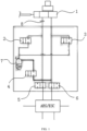
- a bypass energy storage device for an electronically controlled hydraulic braking system, as shown in FIG. 1 , the device comprises a brake master cylinder 1, wherein a first pipeline and a second pipeline are arranged at an outlet end of the brake master cylinder 1, the other end of the first pipeline is connected with a fourth isolation valve 5 for controlling the on-off of the first pipeline, and the other end of the second pipeline is connected with a fifth isolation valve 6 for controlling the on-off of the second pipeline; the other ends of the fourth isolation valve 5 and the fifth isolation valve 6 are both communicated to an ABS/ESC.
- the first pipeline is also connected with a first branch, the other end of the first branch is communicated to an energy accumulator 7, and the first branch is connected with a first inlet valve 2 for controlling the on-off of the first branch; the first pipeline is connected with a pressure sensor 8 for sensing the pressure of the pipeline, and the pressure sensor 8 is located between the first branch and the brake master cylinder 1.
- the second pipeline is also connected with a second branch, the other end of the second branch is also communicated to the energy accumulator 7, the energy accumulator 7 is a spring-type low-pressure energy accumulator 7, and the second branch is connected with a second inlet valve 3 for controlling the on-off of the second branch.
- the energy accumulator 7 is also communicated with a third branch, the other end of the third branch is communicated to the second pipeline, and the third branch is connected with a third return valve 4 for controlling the on-off of the third branch.
- the first inlet valve 2, the second inlet valve 3 and the third return valve 4 are all normally-closed two-position two-way valves, and the fourth isolation valve 5 and the fifth isolation valve 6 are both normally-open two-position two-way valves.
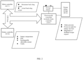
- each valve of the device is controlled to be opened and closed by the electronically controlled hydraulic controller EHC, and the electronically controlled hydraulic controller EHC is also connected with a battery controller BCM and a motor controller MCU via high-speed CAN communication.
- the execution controller receives a control signal of the electronically controlled hydraulic controller EHC and drives each electromagnetic valve which can work independently through a power device of the execution controller so as to control a circulation path of a brake fluid pipeline; a power supply of a storage battery of a vehicle or a direct current-to-direct current converter (DC/DC) is directly connected with the actuator to supply power for the electromagnetic valves and the like, wherein the normal working voltage of the power supply of the storage battery is 9V to 16V, and a liquid level sensor for sensing the liquid storage amount is connected in the liquid storage device.
- DC/DC direct current-to-direct current converter
- the basic control concept of the bypass device system is as follows: the electronically controlled hydraulic controller EHC calculates whether the braking request of a driver and the energy recovery condition are met or not and considers the stability of the vehicle, and sends a feedback braking torque request to the motor controller and simultaneously controls the bypass device.
- the specific control method comprises the following steps:
- the device When the energy recovery function is switched on, the device enters a working state during a pressurization process, and electric braking torque and hydraulic braking torque are distributed; the back-drag torque of the motor is determined by a motor controller or a wheel speed sensor.
- the pressurization process is as follows: after the electronically controlled hydraulic controller detects that the driver steps on the pedal and the whole vehicle simultaneously starts the energy recovery function, the first inlet valve 2 and the second inlet valve 3 are opened, the fourth isolation valve 5 and the fifth isolation valve 6 are closed, and the brake fluid enters the energy accumulator 7 through the brake master cylinder 1, the first inlet valve 2 and the second inlet valve 3.
- Braking forces on wheels are provided by back dragging of a driving motor, the whole vehicle performs a braking energy recovery work, the electronically controlled hydraulic controller monitors the opening degree of the pedal at all times, and magnitudes of a total braking force request and back-drag torque are determined.
- the first inlet valve 2 and the second inlet valve 3 are closed, the fourth isolation valve 5 and the fifth isolation valve 6 are opened, and an insufficient braking force is supplemented with a hydraulic pressure; the back-dragging of the motor and mechanical braking co-work in a serial mode to achieve a deceleration effect of the vehicle.
- Pc is the rechargeable power in a unit of Kw
- n is a rotating speed of the motor in a unit of rpm.
- Corresponding maximum allowable braking torque of the battery is calculated according to a maximum allowable charging power of the battery, and if the maximum allowable braking torque of the battery is smaller than maximum allowable braking torque of the motor, the maximum allowable braking torque of the battery is taken as a maximum electric braking torque request, that is the minimum one of the braking force request, the maximum allowable braking torque of the battery and the maximum allowable braking torque of the motor is taken as a feedback braking torque request, and the EHC sends the feedback braking torque request to the motor controller; in the braking process, the motor controller may send out the currently maximum available back-drag torque of the regenerative braking system through CAN communication; the electronically controlled hydraulic controller EHC may determine whether to allow the vehicle to enter the energy recovery mode and the rechargeable torque command value according to the battery controller BCM charge permission condition and the driver's intention.
- Fe is a braking force of the driving motor in a unit of N.m
- Fh is an electronically controlled hydraulic braking force in a unit of N.m
- F roll is a rolling resistance of the vehicle in a unit of N.m
- f aero is a wind resistance in a unit of N.m
- a is the braking deceleration in a unit of m/s 2
- ⁇ is a rolling resistance coefficient
- M is the mass of the whole vehicle in a unit of kg
- a is a slope angle
- i is a gradient
- a arctan (i).
- step VI when the driver releases the pedal or is in a process of releasing, entering, by the device, a pressure-relief process.
- the pressure-relief process is as follows: in a pressure reduction stage, as the driver releases the pedal or is in a process of releasing, the first inlet valve 2 and the second inlet valve 3 are powered off and closed, the fourth isolation valve 5 and the fifth isolation valve 6 are powered off and opened, and the third return valve 4 is powered on and opened according to pressures of the pipelines, as the brake pedal is not stepped on or a pressure of a main hydraulic circuit is small at the moment, a pressure of the brake master cylinder 1 does not exist, and under the action of the pressure, the brake fluid in the low-pressure energy accumulator 7 returns to the master cylinder through the third return valve 4 under the action of an internal spring.
Landscapes
- Engineering & Computer Science (AREA)
- Transportation (AREA)
- Mechanical Engineering (AREA)
- Power Engineering (AREA)
- Automation & Control Theory (AREA)
- Human Computer Interaction (AREA)
- Combustion & Propulsion (AREA)
- Chemical & Material Sciences (AREA)
- Physics & Mathematics (AREA)
- Electromagnetism (AREA)
- Regulating Braking Force (AREA)
- Control Of Driving Devices And Active Controlling Of Vehicle (AREA)
- Electric Propulsion And Braking For Vehicles (AREA)
Abstract
Description
- The present invention relates to the field of new energy automobile braking systems, and in particular to a bypass energy storage device for an electronically controlled hydraulic braking system and a control method thereof.
- In the modern automobile market, the number of new energy automobiles is increasing, and one of the most concerned problems of people, whether pure electric vehicles or hybrid electric vehicles, is the driving mileage of the automobiles. Almost all new energy automobiles in the market are equipped with an energy recovery function. The braking energy recovery system is a method adopted for prolonging the endurance mileage, wherein the conversion of mechanical energy into electric energy through braking plays a dominant role. However, the recovery of braking energy tends to give drivers a feeling of inconsistent brake pedal stroke.
- The purpose of the present invention is to provide a bypass energy storage device for an electronically controlled hydraulic braking system, wherein under two conditions that a vehicle energy recovery function is switched on and switched off, the vehicle deceleration is the same for the same pedal stroke; for a driver, the strokes of stepping on the brake pedal are consistent, so that the energy consumption can be reduced, and the driver can better control foot feeling, thereby improving the comfort and the safety of products.
- The technical purpose of the present invention is realized by the following technical solution:
Provided is a bypass energy storage device for an electronically controlled hydraulic braking system, which comprises a brake master cylinder, wherein a first pipeline and a second pipeline are arranged at an outlet end of the brake master cylinder, the other end of the first pipeline is connected with a fourth isolation valve for controlling the on-off of the first pipeline, and the other end of the second pipeline is connected with a fifth isolation valve for controlling the on-off of the second pipeline; the other ends of the fourth isolation valve and the fifth isolation valve are both communicated to an ABS/ESC; - the first pipeline is also connected with a first branch, the other end of the first branch is communicated to an energy accumulator, and the first branch is connected with a first inlet valve for controlling the on-off of the first branch;
- the second pipeline is also connected with a second branch, the other end of the second branch is also communicated to the energy accumulator, and the second branch is connected with a second inlet valve for controlling the on-off of the second branch;
- the energy accumulator is also communicated with a third branch, the other end of the third branch is communicated to the first pipeline or the second pipeline, and the third branch is connected with a third return valve for controlling the on-off of the third branch.
- Furthermore, the working state of the device comprises the pressurization process and the pressure-relief process; wherein
- the pressurization process is as follows: after the electronically controlled hydraulic controller detects that the driver steps on the pedal and the whole vehicle simultaneously starts the energy recovery function, the first inlet valve and the second inlet valve are opened, the fourth isolation valve and the fifth isolation valve are closed, and the brake fluid enters the energy accumulator through the brake master cylinder, the first inlet valve and the second inlet valve;
- braking forces on wheels are provided by back dragging of a driving motor, the whole vehicle performs a braking energy recovery work, the electronically controlled hydraulic controller monitors the opening degree of the pedal at all times, and magnitudes of a total braking force request and back-drag torque are determined;
- when the back-drag torque is insufficient, the first inlet valve and the second inlet valve are closed, the fourth isolation valve and the fifth isolation valve are opened, and an insufficient braking force is supplemented with a hydraulic pressure; the back-dragging of the motor and mechanical braking co-work in a serial mode to achieve a deceleration effect of the vehicle;
- the pressure-relief process is as follows: in a pressure reduction stage, as the driver releases the pedal or is in a process of releasing, the first inlet valve and the second inlet valve are powered off and closed, the fourth isolation valve and the fifth isolation valve are powered off and opened, and the third return valve is powered on and opened according to pressures of the pipelines, as the brake pedal is not stepped on or a pressure of a main hydraulic circuit is small at the moment, a pressure of the brake master cylinder does not exist, and under the action of the pressure, the brake fluid in the low-pressure energy accumulator returns to the master cylinder through the third return valve under the action of an internal spring.
- Furthermore, a working condition of the device also comprises a normal condition that when an energy recovery function is switched off and when a driver steps on a brake pedal, all electromagnetic valves are kept in a power-off state, and a brake fluid directly enters the ABS/ESC through the master cylinder, the fourth isolation valve and the fifth isolation valve.
- Furthermore, the first pipeline is connected with a pressure sensor for sensing the pressure of the pipeline.
- Furthermore, the energy accumulator is a spring-type low-pressure energy accumulator.
- Furthermore, each valve of the device is controlled to be opened and closed by the electronically controlled hydraulic controller EHC, and the electronically controlled hydraulic controller EHC is also connected with a battery controller BCM and a motor controller MCU via high-speed CAN communication.
- Another purpose of the present invention is to provide a control method of a bypass energy storage device for an electronically controlled hydraulic braking system, wherein under two conditions that a vehicle energy recovery function is switched on and switched off, for a driver, the strokes of stepping on the brake pedal are consistent, so that the energy consumption can be reduced, and the driver can better control foot feeling, thereby improving the comfort and the safety of products.
- Provided is a control method of a bypass energy storage device for an electronically controlled hydraulic braking system, which comprises the following steps:
- step I: monitoring, by an electronically controlled hydraulic controller, whether a driver has a braking intention or not in real time, specifically comprising acquiring a signal of a displacement sensor of a brake pedal through AD, determining and calculating a depth and a speed of the driver for stepping on the brake pedal, and then obtaining a braking deceleration a required by a vehicle at the moment according to a vehicle braking characteristic matching parameter table;
- step II: determining whether the driver is in emergency braking or not according to an opening degree of the pedal and the speed of stepping on the pedal; if yes, closing the energy recovery function;
- step III: when the energy recovery function is switched off, entering a working state under a normal condition, and directly performing hydraulic braking;
- when the energy recovery function is switched on, entering, by the device, a working state during a pressurization process, and distributing electric braking torque and hydraulic braking torque; and
- step VI: when the driver releases the pedal or is in a process of releasing, entering, by the device, a pressure-relief process.
- Furthermore, in the step II, if the driver is not in emergency braking, the electronically controlled hydraulic controller EHC keeps communication with two systems of the battery controller BCM and the motor controller MCU at all times, so as to determine whether the vehicle is allowed to enter an energy recovery state or not, and the determination is performed according to a judgment basis including constant changes of the back-drag torque of the driving motor along with vehicle speeds, an SOC, a temperature, a current and communication faults of a power battery. Furthermore, in the step III, a reference calculation formula for distributing the braking torque is as follows:
if

- in the formula, Fe is a braking force of the driving motor in a unit of N.m; Fh is an electronically controlled hydraulic braking force in a unit of N.m; Froll is a rolling resistance of the vehicle in a unit of N.m; faero is a wind resistance in a unit of N.m; a is the braking deceleration in a unit of m/s2; m is a mass of the whole vehicle in a unit of kg;
- wherein the rolling resistance of the vehicle can be expressed as follows:

- in the formula, µ is a rolling resistance coefficient; M is the mass of the whole vehicle in a unit of kg; a is a slope angle, i is a gradient, and a = arctan (i);
- the wind resistance of the vehicle can be expressed as follows:

- in the formula, k is a wind resistance coefficient; Af is a frontal area in a unit of m2; V is a speed of the vehicle in a unit of km/h; ρ is an air density and taken as 1.3 kg/m2.
- Furthermore, in the step III, a rechargeable power generates torque

- in the formula, Pc is the rechargeable power in a unit of Kw; n is a rotating speed of the motor in a unit of rpm;
- corresponding maximum allowable braking torque of the battery is calculated according to a maximum allowable charging power of the battery, and if the maximum allowable braking torque of the battery is smaller than maximum allowable braking torque of the motor, the energy recovery function is switched off or the maximum allowable braking torque of the battery is taken as a maximum electric braking torque request.
- In conclusion, the present invention has the following beneficial effects:
Under two conditions that a vehicle energy recovery function is switched on and switched off, for a driver, the vehicle deceleration is the same for the same pedal stroke, and the strokes of stepping on the brake pedal are consistent. The foot feeling gives people a reliable and safe feeling, and simultaneously, part of components can be extracted separately. The energy recovery on a vehicle can not only reduce energy consumption, but also better control foot feeling, thereby improving the comfort and safety of products. -
-
FIG. 1 is a schematic diagram of an overall structure of the present invention; and -
FIG. 2 is a schematic diagram of the electrical connection of the present invention. - In the
figure, 1 is a brake master cylinder; 2 is a first inlet valve; 3 is a second inlet valve; 4 is a third return valve; 5 is a fourth isolation valve; 6 is a fifth isolation valve; 7 is an energy accumulator; 8 is a pressure sensor. - The detailed description of the present invention is further illustrated below with reference to the accompanying drawings, to which, however, the present invention is not limited.
- Provided is a bypass energy storage device for an electronically controlled hydraulic braking system, as shown in
FIG. 1 , the device comprises abrake master cylinder 1, wherein a first pipeline and a second pipeline are arranged at an outlet end of thebrake master cylinder 1, the other end of the first pipeline is connected with afourth isolation valve 5 for controlling the on-off of the first pipeline, and the other end of the second pipeline is connected with a fifth isolation valve 6 for controlling the on-off of the second pipeline; the other ends of thefourth isolation valve 5 and the fifth isolation valve 6 are both communicated to an ABS/ESC. - As shown in
FIG. 1 , the first pipeline is also connected with a first branch, the other end of the first branch is communicated to anenergy accumulator 7, and the first branch is connected with a first inlet valve 2 for controlling the on-off of the first branch; the first pipeline is connected with apressure sensor 8 for sensing the pressure of the pipeline, and thepressure sensor 8 is located between the first branch and thebrake master cylinder 1. - The second pipeline is also connected with a second branch, the other end of the second branch is also communicated to the
energy accumulator 7, theenergy accumulator 7 is a spring-type low-pressure energy accumulator 7, and the second branch is connected with asecond inlet valve 3 for controlling the on-off of the second branch. - The
energy accumulator 7 is also communicated with a third branch, the other end of the third branch is communicated to the second pipeline, and the third branch is connected with athird return valve 4 for controlling the on-off of the third branch. - As shown in
FIG. 1 , in the present embodiment, the first inlet valve 2, thesecond inlet valve 3 and thethird return valve 4 are all normally-closed two-position two-way valves, and thefourth isolation valve 5 and the fifth isolation valve 6 are both normally-open two-position two-way valves. - As shown in
FIG. 2 , each valve of the device is controlled to be opened and closed by the electronically controlled hydraulic controller EHC, and the electronically controlled hydraulic controller EHC is also connected with a battery controller BCM and a motor controller MCU via high-speed CAN communication. The execution controller receives a control signal of the electronically controlled hydraulic controller EHC and drives each electromagnetic valve which can work independently through a power device of the execution controller so as to control a circulation path of a brake fluid pipeline; a power supply of a storage battery of a vehicle or a direct current-to-direct current converter (DC/DC) is directly connected with the actuator to supply power for the electromagnetic valves and the like, wherein the normal working voltage of the power supply of the storage battery is 9V to 16V, and a liquid level sensor for sensing the liquid storage amount is connected in the liquid storage device. - The basic control concept of the bypass device system is as follows: the electronically controlled hydraulic controller EHC calculates whether the braking request of a driver and the energy recovery condition are met or not and considers the stability of the vehicle, and sends a feedback braking torque request to the motor controller and simultaneously controls the bypass device.
- The specific control method comprises the following steps:
- step I: monitoring, by an electronically controlled hydraulic controller, whether a driver has a braking intention or not in real time, specifically comprising acquiring a signal of a displacement sensor of a brake pedal through AD, determining and calculating a depth and a speed of the driver for stepping on the brake pedal, and then obtaining a braking deceleration a required by a vehicle at the moment according to a vehicle braking characteristic matching parameter table;
- step II: determining whether the driver is in emergency braking or not according to an opening degree of the pedal and the speed of stepping on the pedal; if yes, closing the energy recovery function; if the driver is not in emergency braking, the electronically controlled hydraulic controller EHC keeps communication with two systems of the battery controller BCM and the motor controller MCU at all times, so as to determine whether the vehicle is allowed to enter an energy recovery state or not, and the determination is performed according to a judgment basis including constant changes of the back-drag torque of the driving motor along with vehicle speeds, an SOC, a temperature, a current and communication faults of a power battery;
- step III: when the energy recovery function is switched off, entering a working state under a normal condition, and directly performing hydraulic braking;
- wherein the normal condition is as follows: when an energy recovery function is switched off and when a driver steps on a brake pedal, all electromagnetic valves are kept in a power-off state, and a brake fluid directly enters the ABS/ESC through the master cylinder, the
fourth isolation valve 5 and the fifth isolation valve 6 (if the vehicle is not equipped with the ABS/ESC, the brake fluid directly enters the four wheel cylinders), and hydraulic braking is full braking force. - When the energy recovery function is switched on, the device enters a working state during a pressurization process, and electric braking torque and hydraulic braking torque are distributed; the back-drag torque of the motor is determined by a motor controller or a wheel speed sensor.
- The pressurization process is as follows: after the electronically controlled hydraulic controller detects that the driver steps on the pedal and the whole vehicle simultaneously starts the energy recovery function, the first inlet valve 2 and the
second inlet valve 3 are opened, thefourth isolation valve 5 and the fifth isolation valve 6 are closed, and the brake fluid enters theenergy accumulator 7 through thebrake master cylinder 1, the first inlet valve 2 and thesecond inlet valve 3. - Braking forces on wheels are provided by back dragging of a driving motor, the whole vehicle performs a braking energy recovery work, the electronically controlled hydraulic controller monitors the opening degree of the pedal at all times, and magnitudes of a total braking force request and back-drag torque are determined.
- When the back-drag torque is insufficient, the first inlet valve 2 and the
second inlet valve 3 are closed, thefourth isolation valve 5 and the fifth isolation valve 6 are opened, and an insufficient braking force is supplemented with a hydraulic pressure; the back-dragging of the motor and mechanical braking co-work in a serial mode to achieve a deceleration effect of the vehicle. - A rechargeable power generates torque

- In the formula, Pc is the rechargeable power in a unit of Kw; n is a rotating speed of the motor in a unit of rpm.
- Corresponding maximum allowable braking torque of the battery is calculated according to a maximum allowable charging power of the battery, and if the maximum allowable braking torque of the battery is smaller than maximum allowable braking torque of the motor, the maximum allowable braking torque of the battery is taken as a maximum electric braking torque request, that is the minimum one of the braking force request, the maximum allowable braking torque of the battery and the maximum allowable braking torque of the motor is taken as a feedback braking torque request, and the EHC sends the feedback braking torque request to the motor controller; in the braking process, the motor controller may send out the currently maximum available back-drag torque of the regenerative braking system through CAN communication; the electronically controlled hydraulic controller EHC may determine whether to allow the vehicle to enter the energy recovery mode and the rechargeable torque command value according to the battery controller BCM charge permission condition and the driver's intention.
- A reference calculation formula for distributing the braking torque is as follows:
if

- In the formula, Fe is a braking force of the driving motor in a unit of N.m; Fh is an electronically controlled hydraulic braking force in a unit of N.m; Froll is a rolling resistance of the vehicle in a unit of N.m; faero is a wind resistance in a unit of N.m; a is the braking deceleration in a unit of m/s2; m is a mass of the whole vehicle in a unit of kg;
wherein the rolling resistance of the vehicle can be expressed as follows:
- In the formula, µ is a rolling resistance coefficient; M is the mass of the whole vehicle in a unit of kg; a is a slope angle, i is a gradient, and a = arctan (i).
- The wind resistance of the vehicle can be expressed as follows:

- In the formula, k is a wind resistance coefficient; Af is a frontal area in a unit of m2; V is a speed of the vehicle in a unit of km/h; ρ is an air density and taken as 1.3 kg/m2.
step VI: when the driver releases the pedal or is in a process of releasing, entering, by the device, a pressure-relief process. - The pressure-relief process is as follows: in a pressure reduction stage, as the driver releases the pedal or is in a process of releasing, the first inlet valve 2 and the
second inlet valve 3 are powered off and closed, thefourth isolation valve 5 and the fifth isolation valve 6 are powered off and opened, and thethird return valve 4 is powered on and opened according to pressures of the pipelines, as the brake pedal is not stepped on or a pressure of a main hydraulic circuit is small at the moment, a pressure of thebrake master cylinder 1 does not exist, and under the action of the pressure, the brake fluid in the low-pressure energy accumulator 7 returns to the master cylinder through thethird return valve 4 under the action of an internal spring. - The above mentioned contents are only preferred embodiments of the present invention and are not intended to limit the present invention. Various modifications or equivalent substitutions made by those skilled in the art within the spirit and protection scope of the present invention shall fall within the protection scope of the technical solution of the present invention.
Claims (7)
- A control method of a bypass energy storage device for an electronically controlled hydraulic braking system, wherein the bypass energy storage device for the electronically controlled hydraulic braking system used in the control method comprises a brake master cylinder, wherein a first pipeline and a second pipeline are arranged at an outlet end of the brake master cylinder, the other end of the first pipeline is connected with a fourth isolation valve for controlling the on-off of the first pipeline, and the other end of the second pipeline is connected with a fifth isolation valve for controlling the on-off of the second pipeline; the other ends of the fourth isolation valve and the fifth isolation valve are both communicated to an ABS/ESC;the first pipeline is also connected with a first branch, the other end of the first branch is communicated to an energy accumulator, and the first branch is connected with a first inlet valve for controlling the on-off of the first branch;the second pipeline is also connected with a second branch, the other end of the second branch is also communicated to the energy accumulator, and the second branch is connected with a second inlet valve for controlling the on-off of the second branch;the energy accumulator is also communicated with a third branch, the other end of the third branch is communicated to the first pipeline or the second pipeline, and the third branch is connected with a third return valve for controlling the on-off of the third branch;a working condition of the device also comprises a normal condition that when an energy recovery function is switched off and when a driver steps on a brake pedal, all electromagnetic valves are kept in a power-off state, and a brake fluid directly enters the ABS/ESC through the master cylinder, the fourth isolation valve and the fifth isolation valve;the control method comprises the following steps:step I: monitoring, by an electronically controlled hydraulic controller, whether a driver has a braking intention or not in real time, specifically comprising acquiring a signal of a displacement sensor of a brake pedal through AD, determining and calculating a depth and a speed of the driver for stepping on the brake pedal, and then obtaining a braking deceleration a required by a vehicle at the moment according to a vehicle braking characteristic matching parameter table;step II: determining whether the driver is in emergency braking or not according to an opening degree of the pedal and the speed of stepping on the pedal; if yes, closing the energy recovery function;step III: when the energy recovery function is switched off, entering a working state under a normal condition, and directly performing hydraulic braking;when the energy recovery function is switched on, entering, by the device, a working state during a pressurization process, and distributing electric braking torque and hydraulic braking torque; andstep VI: when the driver releases the pedal or is in a process of releasing, entering, by the device, a pressure-relief process;the working state of the device comprises the pressurization process and the pressure-relief process; whereinthe pressurization process is as follows: after the electronically controlled hydraulic controller detects that the driver steps on the pedal and the whole vehicle simultaneously starts the energy recovery function, the first inlet valve and the second inlet valve are opened, the fourth isolation valve and the fifth isolation valve are closed, and the brake fluid enters the energy accumulator through the brake master cylinder, the first inlet valve and the second inlet valve;braking forces on wheels are provided by back dragging of a driving motor, the whole vehicle performs a braking energy recovery work, the electronically controlled hydraulic controller monitors the opening degree of the pedal at all times, and magnitudes of a total braking force request and back-drag torque are determined;when the back-drag torque is insufficient, the first inlet valve and the second inlet valve are closed,the fourth isolation valve and the fifth isolation valve are opened, and an insufficient braking force is supplemented with a hydraulic pressure; the back-dragging of the motor and mechanical braking co-work in a serial mode to achieve a deceleration effect of the vehicle;the pressure-relief process is as follows: in a pressure reduction stage, as the driver releases the pedal or is in a process of releasing, the first inlet valve and the second inlet valve are powered off and closed, the fourth isolation valve and the fifth isolation valve are powered off and opened, andthe third return valve is powered on and opened according to pressures of the pipelines, as the brake pedal is not stepped on or a pressure of a main hydraulic circuit is small at the moment, a pressure of the brake master cylinder does not exist, and under the action of the pressure, the brake fluid in the low-pressure energy accumulator returns to the master cylinder through the third return valve under the action of an internal spring.
- The control method of a bypass energy storage device for an electronically controlled hydraulic braking system according to claim 1, wherein the first pipeline is connected with a pressure sensor for sensing the pressure of the pipeline.
- The control method of a bypass energy storage device for an electronically controlled hydraulic braking system according to claim 1, wherein the energy accumulator is a spring-type low-pressure energy accumulator.
- The control method of a bypass energy storage device for an electronically controlled hydraulic braking system according to claim 1, wherein each valve of the device is controlled to be opened and closed by the electronically controlled hydraulic controller EHC, and the electronically controlled hydraulic controller EHC is also connected with a battery controller BCM and a motor controller MCU via high-speed CAN communication.
- The control method of a bypass energy storage device for an electronically controlled hydraulic braking system according to claim 1, wherein in the step II, if the driver is not in emergency braking, the electronically controlled hydraulic controller EHC keeps communication with two systems of the battery controller BCM and the motor controller MCU at all times, so as to determine whether the vehicle is allowed to enter an energy recovery state or not, and the determination is performed according to a judgment basis including constant changes of the back-drag torque of the driving motor along with vehicle speeds, an SOC, a temperature, a current and communication faults of a power battery.
- The control method of a bypass energy storage device for an electronically controlled hydraulic braking system according to claim 5, wherein,in the step III, a reference calculation formula for distributing the braking torque is as follows:
if
 in the formula, Fe is a braking force of the driving motor in a unit of N.m; Fh is an electronically controlled hydraulic braking force in a unit of N.m; Froll is a rolling resistance of the vehicle in a unit of N.m; faero is a wind resistance in a unit of N.m; a is the braking deceleration in a unit of m/s2; m is a mass of the whole vehicle in a unit of kg;wherein the rolling resistance of the vehicle can be expressed as follows:
 the wind resistance of the vehicle can be expressed as follows:
- The control method of a bypass energy storage device for an electronically controlled hydraulic braking system according to claim 6, wherein,in the step III, a rechargeable power generates torque
 corresponding maximum allowable braking torque of the battery is calculated according to a maximum allowable charging power of the battery, and if the maximum allowable braking torque of the battery is smaller than maximum allowable braking torque of the motor, the energy recovery function is switched off or the maximum allowable braking torque of the battery is taken as a maximum electric braking torque request.
Applications Claiming Priority (2)
| Application Number | Priority Date | Filing Date | Title |
|---|---|---|---|
| CN202010787667.6A CN111907495B (en) | 2020-08-07 | 2020-08-07 | A bypass energy storage device for electronically controlled hydraulic braking system |
| PCT/CN2021/110803 WO2022028519A1 (en) | 2020-08-07 | 2021-08-05 | Bypass energy accumulating device for electronically controlled hydraulic braking system and control method thereof |
Publications (3)
| Publication Number | Publication Date |
|---|---|
| EP4151476A1 true EP4151476A1 (en) | 2023-03-22 |
| EP4151476A4 EP4151476A4 (en) | 2023-10-18 |
| EP4151476B1 EP4151476B1 (en) | 2024-09-25 |
Family
ID=73282990
Family Applications (1)
| Application Number | Title | Priority Date | Filing Date |
|---|---|---|---|
| EP21852973.3A Active EP4151476B1 (en) | 2020-08-07 | 2021-08-05 | Control method for a bypass energy accumulating device of an electronically controlled hydraulic braking system |
Country Status (5)
| Country | Link |
|---|---|
| US (1) | US12377830B2 (en) |
| EP (1) | EP4151476B1 (en) |
| JP (1) | JP7584546B2 (en) |
| CN (1) | CN111907495B (en) |
| WO (1) | WO2022028519A1 (en) |
Families Citing this family (5)
| Publication number | Priority date | Publication date | Assignee | Title |
|---|---|---|---|---|
| CN111907495B (en) * | 2020-08-07 | 2021-07-20 | 格陆博科技有限公司 | A bypass energy storage device for electronically controlled hydraulic braking system |
| JP7662437B2 (en) * | 2021-07-07 | 2025-04-15 | トヨタ自動車株式会社 | Electric vehicles |
| CN116039593B (en) * | 2023-02-17 | 2024-04-26 | 湘潭大学 | Dual-drive brake and control method of hybrid brake-by-wire system |
| CN117429269B (en) * | 2023-12-15 | 2024-04-09 | 中国第一汽车股份有限公司 | Control method for closed-loop braking energy recovery function of new energy vehicle type and vehicle |
| CN118478847B (en) * | 2024-07-15 | 2024-11-08 | 格陆博科技有限公司 | An energy recovery method based on vehicle automatic emergency braking |
Family Cites Families (17)
| Publication number | Priority date | Publication date | Assignee | Title |
|---|---|---|---|---|
| JP3160724B2 (en) * | 1991-12-05 | 2001-04-25 | 本田技研工業株式会社 | Electric vehicle braking system |
| JP2002255018A (en) * | 2001-02-28 | 2002-09-11 | Bosch Braking Systems Co Ltd | Brake system |
| JP3972835B2 (en) * | 2003-02-24 | 2007-09-05 | 日産自動車株式会社 | Electronically controlled hydraulic brake device |
| US20070192010A1 (en) * | 2006-02-16 | 2007-08-16 | Carlstrom Kevin R | Adaptive deceleration control for commercial truck |
| DE102007028070A1 (en) | 2007-06-19 | 2008-12-24 | Lucas Automotive Gmbh | Brake equipment for a land vehicle |
| JP2011230744A (en) * | 2010-04-30 | 2011-11-17 | Toyota Motor Corp | Automobile |
| JP2012051455A (en) * | 2010-09-01 | 2012-03-15 | Hitachi Automotive Systems Ltd | Hydraulic brake control device |
| JP5708295B2 (en) * | 2011-06-24 | 2015-04-30 | 株式会社アドヴィックス | Brake device for vehicle |
| JP6314800B2 (en) * | 2014-11-14 | 2018-04-25 | トヨタ自動車株式会社 | Braking force control system, vehicle, and braking force control method |
| JP6361046B2 (en) * | 2014-12-12 | 2018-07-25 | 日立オートモティブシステムズ株式会社 | Brake device and brake system |
| CN105015528B (en) * | 2015-07-20 | 2018-08-28 | 清华大学 | A kind of electro-motive vehicle hydraulic braking apparatus for adjusting force |
| US10315640B2 (en) | 2016-12-08 | 2019-06-11 | Robert Bosch Gmbh | Vehicle having brake system and method of operating |
| US10308120B2 (en) * | 2017-04-12 | 2019-06-04 | Ford Global Technologies, Llc | Optimizing regenerative braking efficiency in a hybrid vehicle |
| US10696281B2 (en) * | 2017-09-25 | 2020-06-30 | Mando Corporation | Electric brake system and operating method thereof |
| KR102631078B1 (en) | 2018-05-17 | 2024-01-30 | 에이치엘만도 주식회사 | brake system |
| CN209955966U (en) * | 2018-12-28 | 2020-01-17 | 万向钱潮股份有限公司 | Split type electro-hydraulic brake device |
| CN111907495B (en) | 2020-08-07 | 2021-07-20 | 格陆博科技有限公司 | A bypass energy storage device for electronically controlled hydraulic braking system |
-
2020
- 2020-08-07 CN CN202010787667.6A patent/CN111907495B/en active Active
-
2021
- 2021-08-05 WO PCT/CN2021/110803 patent/WO2022028519A1/en not_active Ceased
- 2021-08-05 EP EP21852973.3A patent/EP4151476B1/en active Active
- 2021-08-05 JP JP2022580105A patent/JP7584546B2/en active Active
- 2021-08-05 US US17/927,751 patent/US12377830B2/en active Active
Also Published As
| Publication number | Publication date |
|---|---|
| CN111907495B (en) | 2021-07-20 |
| EP4151476A4 (en) | 2023-10-18 |
| EP4151476B1 (en) | 2024-09-25 |
| CN111907495A (en) | 2020-11-10 |
| US12377830B2 (en) | 2025-08-05 |
| WO2022028519A1 (en) | 2022-02-10 |
| JP2023536787A (en) | 2023-08-30 |
| JP7584546B2 (en) | 2024-11-15 |
| US20230211762A1 (en) | 2023-07-06 |
Similar Documents
| Publication | Publication Date | Title |
|---|---|---|
| EP4151476B1 (en) | Control method for a bypass energy accumulating device of an electronically controlled hydraulic braking system | |
| CN102785654B (en) | A kind of electric control hydraulic braking system and control method thereof | |
| US6516925B1 (en) | System and method for braking a towed conveyance | |
| CN112677772B (en) | Control Method of Automobile Regenerative Braking Control System Based on Electronic Hydraulic Braking | |
| CN104118329B (en) | A kind of Recovering Waste Energy of Braking in Automobiles control system and control method thereof | |
| CN110614921B (en) | Braking energy recovery system of electric commercial vehicle and control method | |
| CN102975702B (en) | A kind of Tandem regenerative brake control method | |
| CN102642474B (en) | Accelerator pedal and brake pedal-based electrically driven automobile feedback brake control method | |
| CN102490617B (en) | Hybrid braking system with active auxiliary braking function and control method | |
| CN106904079A (en) | A kind of regenerating brake control method of pure electric automobile | |
| CN108162766A (en) | A kind of In-wheel motor driving automobile mechanical electronic hydraulic redundant braking system and control method | |
| CN101332774A (en) | Automobile braking energy regeneration control method and system | |
| CN101811443B (en) | Automobile braking energy regeneration control system | |
| CN101327746A (en) | An electric vehicle braking system | |
| CN108340898A (en) | One kind considering brake coordination, safety follows electormagnetic braking sytem and its control method with energy-efficient caravan trailer | |
| CN102837687A (en) | Braking device for vehicle | |
| CN202491793U (en) | Drive-by-wire brake system energy regeneration device | |
| CN110001609A (en) | A kind of four-wheel wheel hub driving electric car line traffic control electric braking control device | |
| CN102556034B (en) | Braking energy recovery system based on hydraulic ABS (anti-lock braking system) pressure regulator | |
| CN201677873U (en) | Hydraulic brake system | |
| CN206781542U (en) | A kind of hybrid power tractor brakes with retarder | |
| CN110466361A (en) | Two-wheeled In-wheel motor driving pure electric vehicle controller and control method | |
| CN111674263A (en) | A kind of auxiliary braking method and system for vehicle | |
| CN210554751U (en) | Electro-hydraulic coupling line control power-assisted braking system | |
| CN102765378B (en) | Braking energy recycling device of electric automobile and method for controlling braking energy recycling device |
Legal Events
| Date | Code | Title | Description |
|---|---|---|---|
| STAA | Information on the status of an ep patent application or granted ep patent |
Free format text: STATUS: THE INTERNATIONAL PUBLICATION HAS BEEN MADE |
|
| PUAI | Public reference made under article 153(3) epc to a published international application that has entered the european phase |
Free format text: ORIGINAL CODE: 0009012 |
|
| STAA | Information on the status of an ep patent application or granted ep patent |
Free format text: STATUS: REQUEST FOR EXAMINATION WAS MADE |
|
| 17P | Request for examination filed |
Effective date: 20221215 |
|
| AK | Designated contracting states |
Kind code of ref document: A1 Designated state(s): AL AT BE BG CH CY CZ DE DK EE ES FI FR GB GR HR HU IE IS IT LI LT LU LV MC MK MT NL NO PL PT RO RS SE SI SK SM TR |
|
| A4 | Supplementary search report drawn up and despatched |
Effective date: 20230915 |
|
| RIC1 | Information provided on ipc code assigned before grant |
Ipc: B60L 7/24 20060101ALI20230911BHEP Ipc: B60L 7/10 20060101ALI20230911BHEP Ipc: B60T 17/22 20060101ALI20230911BHEP Ipc: B60T 7/04 20060101ALI20230911BHEP Ipc: B60T 13/68 20060101ALI20230911BHEP Ipc: B60T 1/10 20060101ALI20230911BHEP Ipc: B60T 13/12 20060101AFI20230911BHEP |
|
| DAV | Request for validation of the european patent (deleted) | ||
| DAX | Request for extension of the european patent (deleted) | ||
| GRAP | Despatch of communication of intention to grant a patent |
Free format text: ORIGINAL CODE: EPIDOSNIGR1 |
|
| STAA | Information on the status of an ep patent application or granted ep patent |
Free format text: STATUS: GRANT OF PATENT IS INTENDED |
|
| RIC1 | Information provided on ipc code assigned before grant |
Ipc: B60L 7/24 20060101ALI20240226BHEP Ipc: B60L 7/10 20060101ALI20240226BHEP Ipc: B60T 17/22 20060101ALI20240226BHEP Ipc: B60T 7/04 20060101ALI20240226BHEP Ipc: B60T 13/68 20060101ALI20240226BHEP Ipc: B60T 1/10 20060101ALI20240226BHEP Ipc: B60T 13/12 20060101AFI20240226BHEP |
|
| INTG | Intention to grant announced |
Effective date: 20240322 |
|
| GRAF | Information related to payment of grant fee modified |
Free format text: ORIGINAL CODE: EPIDOSCIGR3 |
|
| GRAS | Grant fee paid |
Free format text: ORIGINAL CODE: EPIDOSNIGR3 |
|
| GRAA | (expected) grant |
Free format text: ORIGINAL CODE: 0009210 |
|
| STAA | Information on the status of an ep patent application or granted ep patent |
Free format text: STATUS: THE PATENT HAS BEEN GRANTED |
|
| AK | Designated contracting states |
Kind code of ref document: B1 Designated state(s): AL AT BE BG CH CY CZ DE DK EE ES FI FR GB GR HR HU IE IS IT LI LT LU LV MC MK MT NL NO PL PT RO RS SE SI SK SM TR |
|
| REG | Reference to a national code |
Ref country code: GB Ref legal event code: FG4D |
|
| REG | Reference to a national code |
Ref country code: CH Ref legal event code: EP |
|
| REG | Reference to a national code |
Ref country code: DE Ref legal event code: R096 Ref document number: 602021019444 Country of ref document: DE |
|
| REG | Reference to a national code |
Ref country code: IE Ref legal event code: FG4D |
|
| REG | Reference to a national code |
Ref country code: LT Ref legal event code: MG9D |
|
| PG25 | Lapsed in a contracting state [announced via postgrant information from national office to epo] |
Ref country code: NO Free format text: LAPSE BECAUSE OF FAILURE TO SUBMIT A TRANSLATION OF THE DESCRIPTION OR TO PAY THE FEE WITHIN THE PRESCRIBED TIME-LIMIT Effective date: 20241225 |
|
| PG25 | Lapsed in a contracting state [announced via postgrant information from national office to epo] |
Ref country code: GR Free format text: LAPSE BECAUSE OF FAILURE TO SUBMIT A TRANSLATION OF THE DESCRIPTION OR TO PAY THE FEE WITHIN THE PRESCRIBED TIME-LIMIT Effective date: 20241226 Ref country code: FI Free format text: LAPSE BECAUSE OF FAILURE TO SUBMIT A TRANSLATION OF THE DESCRIPTION OR TO PAY THE FEE WITHIN THE PRESCRIBED TIME-LIMIT Effective date: 20240925 |
|
| PG25 | Lapsed in a contracting state [announced via postgrant information from national office to epo] |
Ref country code: BG Free format text: LAPSE BECAUSE OF FAILURE TO SUBMIT A TRANSLATION OF THE DESCRIPTION OR TO PAY THE FEE WITHIN THE PRESCRIBED TIME-LIMIT Effective date: 20240925 |
|
| PG25 | Lapsed in a contracting state [announced via postgrant information from national office to epo] |
Ref country code: LV Free format text: LAPSE BECAUSE OF FAILURE TO SUBMIT A TRANSLATION OF THE DESCRIPTION OR TO PAY THE FEE WITHIN THE PRESCRIBED TIME-LIMIT Effective date: 20240925 |
|
| PG25 | Lapsed in a contracting state [announced via postgrant information from national office to epo] |
Ref country code: RS Free format text: LAPSE BECAUSE OF FAILURE TO SUBMIT A TRANSLATION OF THE DESCRIPTION OR TO PAY THE FEE WITHIN THE PRESCRIBED TIME-LIMIT Effective date: 20241225 |
|
| REG | Reference to a national code |
Ref country code: NL Ref legal event code: MP Effective date: 20240925 |
|
| PG25 | Lapsed in a contracting state [announced via postgrant information from national office to epo] |
Ref country code: RS Free format text: LAPSE BECAUSE OF FAILURE TO SUBMIT A TRANSLATION OF THE DESCRIPTION OR TO PAY THE FEE WITHIN THE PRESCRIBED TIME-LIMIT Effective date: 20241225 Ref country code: NO Free format text: LAPSE BECAUSE OF FAILURE TO SUBMIT A TRANSLATION OF THE DESCRIPTION OR TO PAY THE FEE WITHIN THE PRESCRIBED TIME-LIMIT Effective date: 20241225 Ref country code: LV Free format text: LAPSE BECAUSE OF FAILURE TO SUBMIT A TRANSLATION OF THE DESCRIPTION OR TO PAY THE FEE WITHIN THE PRESCRIBED TIME-LIMIT Effective date: 20240925 Ref country code: GR Free format text: LAPSE BECAUSE OF FAILURE TO SUBMIT A TRANSLATION OF THE DESCRIPTION OR TO PAY THE FEE WITHIN THE PRESCRIBED TIME-LIMIT Effective date: 20241226 Ref country code: FI Free format text: LAPSE BECAUSE OF FAILURE TO SUBMIT A TRANSLATION OF THE DESCRIPTION OR TO PAY THE FEE WITHIN THE PRESCRIBED TIME-LIMIT Effective date: 20240925 Ref country code: BG Free format text: LAPSE BECAUSE OF FAILURE TO SUBMIT A TRANSLATION OF THE DESCRIPTION OR TO PAY THE FEE WITHIN THE PRESCRIBED TIME-LIMIT Effective date: 20240925 |
|
| REG | Reference to a national code |
Ref country code: AT Ref legal event code: MK05 Ref document number: 1726435 Country of ref document: AT Kind code of ref document: T Effective date: 20240925 |
|
| PG25 | Lapsed in a contracting state [announced via postgrant information from national office to epo] |
Ref country code: NL Free format text: LAPSE BECAUSE OF FAILURE TO SUBMIT A TRANSLATION OF THE DESCRIPTION OR TO PAY THE FEE WITHIN THE PRESCRIBED TIME-LIMIT Effective date: 20240925 |
|
| PG25 | Lapsed in a contracting state [announced via postgrant information from national office to epo] |
Ref country code: PT Free format text: LAPSE BECAUSE OF FAILURE TO SUBMIT A TRANSLATION OF THE DESCRIPTION OR TO PAY THE FEE WITHIN THE PRESCRIBED TIME-LIMIT Effective date: 20250127 Ref country code: IS Free format text: LAPSE BECAUSE OF FAILURE TO SUBMIT A TRANSLATION OF THE DESCRIPTION OR TO PAY THE FEE WITHIN THE PRESCRIBED TIME-LIMIT Effective date: 20250125 |
|
| PG25 | Lapsed in a contracting state [announced via postgrant information from national office to epo] |
Ref country code: RO Free format text: LAPSE BECAUSE OF FAILURE TO SUBMIT A TRANSLATION OF THE DESCRIPTION OR TO PAY THE FEE WITHIN THE PRESCRIBED TIME-LIMIT Effective date: 20240925 Ref country code: SM Free format text: LAPSE BECAUSE OF FAILURE TO SUBMIT A TRANSLATION OF THE DESCRIPTION OR TO PAY THE FEE WITHIN THE PRESCRIBED TIME-LIMIT Effective date: 20240925 |
|
| PG25 | Lapsed in a contracting state [announced via postgrant information from national office to epo] |
Ref country code: ES Free format text: LAPSE BECAUSE OF FAILURE TO SUBMIT A TRANSLATION OF THE DESCRIPTION OR TO PAY THE FEE WITHIN THE PRESCRIBED TIME-LIMIT Effective date: 20240925 |
|
| PG25 | Lapsed in a contracting state [announced via postgrant information from national office to epo] |
Ref country code: AT Free format text: LAPSE BECAUSE OF FAILURE TO SUBMIT A TRANSLATION OF THE DESCRIPTION OR TO PAY THE FEE WITHIN THE PRESCRIBED TIME-LIMIT Effective date: 20240925 Ref country code: EE Free format text: LAPSE BECAUSE OF FAILURE TO SUBMIT A TRANSLATION OF THE DESCRIPTION OR TO PAY THE FEE WITHIN THE PRESCRIBED TIME-LIMIT Effective date: 20240925 |
|
| PG25 | Lapsed in a contracting state [announced via postgrant information from national office to epo] |
Ref country code: CZ Free format text: LAPSE BECAUSE OF FAILURE TO SUBMIT A TRANSLATION OF THE DESCRIPTION OR TO PAY THE FEE WITHIN THE PRESCRIBED TIME-LIMIT Effective date: 20240925 Ref country code: PL Free format text: LAPSE BECAUSE OF FAILURE TO SUBMIT A TRANSLATION OF THE DESCRIPTION OR TO PAY THE FEE WITHIN THE PRESCRIBED TIME-LIMIT Effective date: 20240925 |
|
| PG25 | Lapsed in a contracting state [announced via postgrant information from national office to epo] |
Ref country code: IT Free format text: LAPSE BECAUSE OF FAILURE TO SUBMIT A TRANSLATION OF THE DESCRIPTION OR TO PAY THE FEE WITHIN THE PRESCRIBED TIME-LIMIT Effective date: 20240925 Ref country code: SK Free format text: LAPSE BECAUSE OF FAILURE TO SUBMIT A TRANSLATION OF THE DESCRIPTION OR TO PAY THE FEE WITHIN THE PRESCRIBED TIME-LIMIT Effective date: 20240925 |
|
| REG | Reference to a national code |
Ref country code: DE Ref legal event code: R097 Ref document number: 602021019444 Country of ref document: DE |
|
| PG25 | Lapsed in a contracting state [announced via postgrant information from national office to epo] |
Ref country code: DK Free format text: LAPSE BECAUSE OF FAILURE TO SUBMIT A TRANSLATION OF THE DESCRIPTION OR TO PAY THE FEE WITHIN THE PRESCRIBED TIME-LIMIT Effective date: 20240925 |
|
| PLBE | No opposition filed within time limit |
Free format text: ORIGINAL CODE: 0009261 |
|
| STAA | Information on the status of an ep patent application or granted ep patent |
Free format text: STATUS: NO OPPOSITION FILED WITHIN TIME LIMIT |
|
| 26N | No opposition filed |
Effective date: 20250626 |
|
| PG25 | Lapsed in a contracting state [announced via postgrant information from national office to epo] |
Ref country code: SE Free format text: LAPSE BECAUSE OF FAILURE TO SUBMIT A TRANSLATION OF THE DESCRIPTION OR TO PAY THE FEE WITHIN THE PRESCRIBED TIME-LIMIT Effective date: 20240925 |
|
| PGFP | Annual fee paid to national office [announced via postgrant information from national office to epo] |
Ref country code: FR Payment date: 20250811 Year of fee payment: 5 |
|
| PG25 | Lapsed in a contracting state [announced via postgrant information from national office to epo] |
Ref country code: HR Free format text: LAPSE BECAUSE OF FAILURE TO SUBMIT A TRANSLATION OF THE DESCRIPTION OR TO PAY THE FEE WITHIN THE PRESCRIBED TIME-LIMIT Effective date: 20240925 |
|
| REG | Reference to a national code |
Ref country code: DE Ref legal event code: R119 Ref document number: 602021019444 Country of ref document: DE |
|
| REG | Reference to a national code |
Ref country code: CH Ref legal event code: H13 Free format text: ST27 STATUS EVENT CODE: U-0-0-H10-H13 (AS PROVIDED BY THE NATIONAL OFFICE) Effective date: 20260324 |
|
| PG25 | Lapsed in a contracting state [announced via postgrant information from national office to epo] |
Ref country code: MC Free format text: LAPSE BECAUSE OF FAILURE TO SUBMIT A TRANSLATION OF THE DESCRIPTION OR TO PAY THE FEE WITHIN THE PRESCRIBED TIME-LIMIT Effective date: 20240925 |
|
| PG25 | Lapsed in a contracting state [announced via postgrant information from national office to epo] |
Ref country code: LU Free format text: LAPSE BECAUSE OF NON-PAYMENT OF DUE FEES Effective date: 20250805 |
|
| PG25 | Lapsed in a contracting state [announced via postgrant information from national office to epo] |
Ref country code: CH Free format text: LAPSE BECAUSE OF NON-PAYMENT OF DUE FEES Effective date: 20250831 |