EP4151442A1 - Hydrogen fuel tank mounting system - Google Patents
Hydrogen fuel tank mounting system Download PDFInfo
- Publication number
- EP4151442A1 EP4151442A1 EP21198143.6A EP21198143A EP4151442A1 EP 4151442 A1 EP4151442 A1 EP 4151442A1 EP 21198143 A EP21198143 A EP 21198143A EP 4151442 A1 EP4151442 A1 EP 4151442A1
- Authority
- EP
- European Patent Office
- Prior art keywords
- fuel tank
- mount
- fuel
- vehicle
- mounting system
- Prior art date
- Legal status (The legal status is an assumption and is not a legal conclusion. Google has not performed a legal analysis and makes no representation as to the accuracy of the status listed.)
- Granted
Links
Images


Classifications
-
- B—PERFORMING OPERATIONS; TRANSPORTING
- B60—VEHICLES IN GENERAL
- B60K—ARRANGEMENT OR MOUNTING OF PROPULSION UNITS OR OF TRANSMISSIONS IN VEHICLES; ARRANGEMENT OR MOUNTING OF PLURAL DIVERSE PRIME-MOVERS IN VEHICLES; AUXILIARY DRIVES FOR VEHICLES; INSTRUMENTATION OR DASHBOARDS FOR VEHICLES; ARRANGEMENTS IN CONNECTION WITH COOLING, AIR INTAKE, GAS EXHAUST OR FUEL SUPPLY OF PROPULSION UNITS IN VEHICLES
- B60K15/00—Arrangement in connection with fuel supply of combustion engines or other fuel consuming energy converters, e.g. fuel cells; Mounting or construction of fuel tanks
- B60K15/03—Fuel tanks
- B60K15/03006—Gas tanks
-
- B—PERFORMING OPERATIONS; TRANSPORTING
- B60—VEHICLES IN GENERAL
- B60K—ARRANGEMENT OR MOUNTING OF PROPULSION UNITS OR OF TRANSMISSIONS IN VEHICLES; ARRANGEMENT OR MOUNTING OF PLURAL DIVERSE PRIME-MOVERS IN VEHICLES; AUXILIARY DRIVES FOR VEHICLES; INSTRUMENTATION OR DASHBOARDS FOR VEHICLES; ARRANGEMENTS IN CONNECTION WITH COOLING, AIR INTAKE, GAS EXHAUST OR FUEL SUPPLY OF PROPULSION UNITS IN VEHICLES
- B60K15/00—Arrangement in connection with fuel supply of combustion engines or other fuel consuming energy converters, e.g. fuel cells; Mounting or construction of fuel tanks
- B60K15/03—Fuel tanks
- B60K15/063—Arrangement of tanks
- B60K15/067—Mounting of tanks
- B60K15/07—Mounting of tanks of gas tanks
-
- B—PERFORMING OPERATIONS; TRANSPORTING
- B60—VEHICLES IN GENERAL
- B60K—ARRANGEMENT OR MOUNTING OF PROPULSION UNITS OR OF TRANSMISSIONS IN VEHICLES; ARRANGEMENT OR MOUNTING OF PLURAL DIVERSE PRIME-MOVERS IN VEHICLES; AUXILIARY DRIVES FOR VEHICLES; INSTRUMENTATION OR DASHBOARDS FOR VEHICLES; ARRANGEMENTS IN CONNECTION WITH COOLING, AIR INTAKE, GAS EXHAUST OR FUEL SUPPLY OF PROPULSION UNITS IN VEHICLES
- B60K15/00—Arrangement in connection with fuel supply of combustion engines or other fuel consuming energy converters, e.g. fuel cells; Mounting or construction of fuel tanks
- B60K15/03—Fuel tanks
- B60K15/063—Arrangement of tanks
- B60K15/067—Mounting of tanks
-
- B—PERFORMING OPERATIONS; TRANSPORTING
- B60—VEHICLES IN GENERAL
- B60K—ARRANGEMENT OR MOUNTING OF PROPULSION UNITS OR OF TRANSMISSIONS IN VEHICLES; ARRANGEMENT OR MOUNTING OF PLURAL DIVERSE PRIME-MOVERS IN VEHICLES; AUXILIARY DRIVES FOR VEHICLES; INSTRUMENTATION OR DASHBOARDS FOR VEHICLES; ARRANGEMENTS IN CONNECTION WITH COOLING, AIR INTAKE, GAS EXHAUST OR FUEL SUPPLY OF PROPULSION UNITS IN VEHICLES
- B60K15/00—Arrangement in connection with fuel supply of combustion engines or other fuel consuming energy converters, e.g. fuel cells; Mounting or construction of fuel tanks
- B60K15/03—Fuel tanks
- B60K2015/03309—Tanks specially adapted for particular fuels
- B60K2015/03315—Tanks specially adapted for particular fuels for hydrogen
-
- Y—GENERAL TAGGING OF NEW TECHNOLOGICAL DEVELOPMENTS; GENERAL TAGGING OF CROSS-SECTIONAL TECHNOLOGIES SPANNING OVER SEVERAL SECTIONS OF THE IPC; TECHNICAL SUBJECTS COVERED BY FORMER USPC CROSS-REFERENCE ART COLLECTIONS [XRACs] AND DIGESTS
- Y02—TECHNOLOGIES OR APPLICATIONS FOR MITIGATION OR ADAPTATION AGAINST CLIMATE CHANGE
- Y02E—REDUCTION OF GREENHOUSE GAS [GHG] EMISSIONS, RELATED TO ENERGY GENERATION, TRANSMISSION OR DISTRIBUTION
- Y02E60/00—Enabling technologies; Technologies with a potential or indirect contribution to GHG emissions mitigation
- Y02E60/30—Hydrogen technology
- Y02E60/32—Hydrogen storage
Definitions
- the present disclosure concerns a system for mounting a hydrogen fuel tank in a vehicle, a hydrogen fuel system, and a vehicle that include such a mounting system, and a method of assembling such a hydrogen fuel system for attachment to a vehicle.
- a mounting system for a fuel tank comprising a first mount configured to mount a first portion of the fuel tank in a fixed position on a vehicle, and a second mount configured to mount a second portion of the fuel tank on the vehicle to allow movement of at least part of the second portion of the fuel tank relative to the second mount.
- the first mount may be configured to mount a first elongated neck portion of a dual port fuel tank, directly or indirectly, to a vehicle chassis
- the second mount may be configured to slidably mount a second elongated neck portion of the dual port fuel tank to the vehicle chassis.
- the second mount allows movement of at least part of the second portion of the fuel tank, stresses on fuel pipes connected to the fuel tank, the first and second mounts, and other vehicle components may be reduced. This can, in turn, improve durability of the fuel system and vehicle and/or allow for reduced manufacturing tolerances.
- the first mount may be a bracket comprising a body portion and a cap portion that, when attached together, form an aperture to receive the first portion of the fuel tank, connected together by at least one fastener.
- the fastener may be configured to attach the body portion to the cap portion with a clearance between the body portion and the cap portion. Such a clearance may reduce shear forces exerted on the first mount that would otherwise be experienced at an interface between the body portion and the cap portion, for example, in response to expansion or contraction of the fuel tank or shocks arising from sudden changes in motion of a vehicle.
- a sleeve may be provided around at least part of the fastener to increase a region of the first mount over which such shear forces are distributed.
- a sleeve e.g., a hollow dowel, that extends through at least a part of the body portion and at least a part of the cap portion.
- the second mount may provide an aperture to receive the second portion of the fuel tank, configured to allow sliding motion of the at least part of the second portion of the fuel tank through the aperture.
- An insert may surround an inner surface of the aperture, formed of a material that provides surface along which the second portion can slide with reduced friction. The provision of a relative low friction surface improves the effectiveness with which the sliding motion and, therefore, the expansion and contraction of the fuel tank, is accommodated, as well as reducing wear on the second portion.
- the insert may include a circumferential groove configured to receive the inner surface of the aperture. By locating the inner surface of the aperture within such a groove, movement of the insert along a direction of the sliding motion, relative to the aperture, can be reduced or avoided altogether.
- the second mount may be a bracket comprising a body portion and a cap portion that, when attached together, are arranged to receive the second portion of the fuel tank, and at least one fastener that attaches the body portion of the second mount to the cap portion of the second mount.
- the body portion and the cap portion of the second mount may be attached to one another using one or more bolts.
- Such fasteners can assist in reducing forces arising from sudden changes in the motion of the vehicle, improving the durability of the mounting system, fuel system and vehicle.
- a hydrogen fuel system comprising a fuel tank configured to store gaseous fuel, and a mounting system according to the first aspect.
- the fuel tank may be a dual port fuel tank with first and second elongated neck portions, where the first mount receives the first elongated neck portion and the second mount receives the second elongated neck portion.
- a vehicle including the above mounting system and/or hydrogen fuel system.
- a method of assembling a fuel system comprising attaching a first mount at a fixed position to a first portion of a fuel tank, attaching a second mount to a second portion of a fuel tank, wherein the second mount permits sliding motion of part of the second portion through the second mount, and attaching the first and second mounts, directly or indirectly, to a vehicle.
- the method may comprise i) attaching a body portion of the first mount and a body portion of the second mount to the vehicle, ii) assembling an insert of the second mount to a second portion the fuel tank, iii) installing the fuel tank on the vehicle such that a first portion of the fuel tank engages the body portion of the first mount, and the insert is seated on the body portion of the second mount, iv) attaching a cap portion of the first mount to the body portion of the first mount to rigidly fix the first portion of the fuel tank to the vehicle, and v) attaching a cap portion of the second mount to the body portion of the second mount to slidably secure the second portion of the fuel tank to the vehicle.
- a fuel system 100 is mounted in a cradle 102 and attached to a vehicle chassis 104.
- the fuel system 100 includes four hydrogen fuel tanks 106a-d arranged to supply hydrogen gas to a fuel cell 108.
- the fuel system 100 also includes batteries 110, 112, inverter 114, distribution unit 116.
- the fuel tanks 106a-d are attached to the cradle 102 by respective first and second mounts.
- fuel tank 106a is attached by first mount 118a and second mount 120a.
- Figure 2 is a view of the cradle 102 with the fuel tanks 106a-106d removed, allowing the first mounts 118a-d for respective fuel tanks 106a-d and the second mount 120c for fuel tank 106c to be shown more clearly.
- Figures 3 and 4 depict one of the fuel tanks 106a of the fuel system 100.
- the fuel tank 106a is a dual port fuel tank including first and second elongated neck portions 122, 124.
- the first elongated neck portion 122 is attached to the chassis 104 via the cradle 102 and the first mount 118a, while the second elongated neck portion 124 is attached to the chassis 104 via the cradle 102 and the second mount 120a.
- the first and second mounts 118a, 120a each include an aperture 126, 128 configured to receive respective ones of the neck portions 122, 124 of the fuel tank 106a.
- the first mount 118a is configured to hold the first elongated neck portion 122 in a fixed position, while the second mount 120a is configured to allow sliding motion of the second elongated neck portion 124 through the aperture 128, along the x direction indicated in Figure 3 .
- the hydrogen fuel tank 106a may expand while being filled. An expansion of the fuel tank 106a will cause sliding motion of the second neck portion 124 through the aperture 128 of the second mount 120a along the negative x direction, while the first neck portion 122 remains fixed in position by the first mount 118a. Such sliding motion of part of the fuel tank 106a allows the expansion of the fuel tank 106a to be accommodated within the fuel system 100 with reduced stress on the components of the fuel system 100, when compared with systems using only fixed mountings.
- contraction of the fuel tank 106a as the amount of hydrogen stored in the fuel tank 106a decreases causes sliding motion of the second neck portion 124 through the aperture 128 in the positive x direction, allowing the contraction to be accommodated with limited stress on the components of the fuel system 100.
- Figure 5 depicts an example first mount 118a for use in the fuel system 100 of Figure 1 , where a portion of the first mount 118a on the left of Figure 5 is shown in section.
- the first mount 118a includes a body portion 130 and a cap portion 132, which form the aperture 126 when attached together by at least one fastener.
- the body portion 130 and cap portion 132 are attached together by one or more bolts 134a that extend through at least part of the body portion 130 and at least part of the cap portion 132.
- the fastener may be configured to provide a clearance 136 between adjacent surfaces of the body portion 130 and cap portion 132 when attached together. Such a clearance may reduce the effect of shear forces that would be present at the interface between the body portion 130 and cap portion 132 if their adjacent surfaces were in contact, or close contact, e.g., when clamping one end of the fuel tank to the vehicle.
- a sleeve 138 is provided around each fastener and extends into at least a part of the body portion 130 and at least a part of the cap portion 132.
- a sleeve 138 such as a hollow dowel, is provided around a part of a shaft 140 of each bolt 134a.
- Such a sleeve 138 can distribute any shear forces experienced by the bolt 134a along its shaft 140, e.g., due to loading of the cap portion 132 relative to the body portion 130.
- the clearance 136 and the sleeve 138 can limit localisation of stresses on at least one of the fastener, the body portion 130 and cap portion 132, improving the durability of the first mount 118a.
- the first mount 118a may be attached to the cradle 102 using bolts 142a, 142b or other fasteners. In other examples, the first mount 118a may be attached directly to the chassis 104 and/or to another part of a vehicle.
- Figure 6 depicts an example second mount 120a for use in the fuel system 100 of Figure 1 , where a portion of the second mount 120a on the right of Figure 6 is shown in section.
- the second mount 120a includes a body portion 144 and a cap portion 146, which form the aperture 128 when attached together.
- the body portion 144 and cap portion 146 are attached together by at least one fastener.
- the at least one fastener includes a bolt 148a that extends through at least part of the body portion 144 and at least part of the cap portion 146 of the second mount 120a, to clamp the body portion 144 and the cap portion 146 together.
- the second mount 120a may be attached to the cradle 102, the chassis 104, or another part of a vehicle, using fasteners such as bolts 150a, 150b.
- the insert 152 is provided that surrounds an inner surface of the aperture 128.
- the insert 152 may be formed of a material that reduces friction when the second neck portion 124 of the fuel tank 106a slides through the aperture 128.
- the insert 152 is formed of a plastics material.
- the insert 152 may include a circumferential groove 154, configured to receive the inner surface of the aperture 128. Because the inner surface of the aperture 128 is located within the groove 154, contact between the inner surfaces of the groove 154 and sides of the body portion 144 and the cap portion 146 resists motion of the insert 152 along the x direction. In this manner, the insert 152 is held in position when the second neck portion 124 is sliding through the aperture 128.
- the body portion 144 and the cap portion may be sized to ensure that tightening of a fastener, e.g., bolt 148a, does not substantially deform, e.g., by more than 10 microns or 100 microns, an inner opening of the insert 152 upon clamping the body portion 144 and the cap portion 146 together. In this manner, excessive clamping force is not applied to a portion of the fuel tank that is secured in the second mount 120a.
- a fastener e.g., bolt 148a
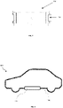
- FIG 8 shows an example of a vehicle 800 in which the fuel system may be installed.
- the vehicle 800 includes the fuel system 100 described above with reference to Figure 1 , located in the cradle 102 and attached to the underside of the chassis 104.
- the fuel system 100 may be attached, directly or indirectly, to the chassis 104 or to another part of the vehicle.
- the mounting system described above may be used to mount fuel tanks in other vehicles, including vans, trucks, coaches, buses, trucks, lorries, or any other appropriate vehicle. In some examples the mounting system described above may be used to mount fuel tanks in other applications, such as power generators, etc.
Landscapes
- Engineering & Computer Science (AREA)
- Life Sciences & Earth Sciences (AREA)
- Sustainable Development (AREA)
- Sustainable Energy (AREA)
- Chemical & Material Sciences (AREA)
- Combustion & Propulsion (AREA)
- Transportation (AREA)
- Mechanical Engineering (AREA)
- Cooling, Air Intake And Gas Exhaust, And Fuel Tank Arrangements In Propulsion Units (AREA)
Abstract
Description
- The present disclosure concerns a system for mounting a hydrogen fuel tank in a vehicle, a hydrogen fuel system, and a vehicle that include such a mounting system, and a method of assembling such a hydrogen fuel system for attachment to a vehicle.
- The use of hydrogen as a fuel for automobiles and other transportation vehicles is expected to increase in popularity in the near future. Onboard storage of hydrogen presents a number of challenges. Because of its low energy to volume ratio, hydrogen gas is often stored in a tank and kept at a high pressure, e.g., 5,000 - 10,000 psi (350 - 700 bar). These challenges may be particularly marked in the storage of hydrogen in light vehicles, such as automobiles, limiting the potential size and weight of the storage tank. In particular, a hydrogen storage tank may expand while being filled and contract while hydrogen is depleted through consumption.
- According to a first aspect, there is provided a mounting system for a fuel tank, comprising a first mount configured to mount a first portion of the fuel tank in a fixed position on a vehicle, and a second mount configured to mount a second portion of the fuel tank on the vehicle to allow movement of at least part of the second portion of the fuel tank relative to the second mount. For example, the first mount may be configured to mount a first elongated neck portion of a dual port fuel tank, directly or indirectly, to a vehicle chassis, and the second mount may be configured to slidably mount a second elongated neck portion of the dual port fuel tank to the vehicle chassis.
- Because the second mount allows movement of at least part of the second portion of the fuel tank, stresses on fuel pipes connected to the fuel tank, the first and second mounts, and other vehicle components may be reduced. This can, in turn, improve durability of the fuel system and vehicle and/or allow for reduced manufacturing tolerances.
- The first mount may be a bracket comprising a body portion and a cap portion that, when attached together, form an aperture to receive the first portion of the fuel tank, connected together by at least one fastener. The fastener may be configured to attach the body portion to the cap portion with a clearance between the body portion and the cap portion. Such a clearance may reduce shear forces exerted on the first mount that would otherwise be experienced at an interface between the body portion and the cap portion, for example, in response to expansion or contraction of the fuel tank or shocks arising from sudden changes in motion of a vehicle.
- A sleeve may be provided around at least part of the fastener to increase a region of the first mount over which such shear forces are distributed. For example, where the body portion and the cap portion of the first mount are attached together using one or more bolts, at least a part of a shaft of each bolt may be covered by a sleeve, e.g., a hollow dowel, that extends through at least a part of the body portion and at least a part of the cap portion.
- The second mount may provide an aperture to receive the second portion of the fuel tank, configured to allow sliding motion of the at least part of the second portion of the fuel tank through the aperture. An insert may surround an inner surface of the aperture, formed of a material that provides surface along which the second portion can slide with reduced friction. The provision of a relative low friction surface improves the effectiveness with which the sliding motion and, therefore, the expansion and contraction of the fuel tank, is accommodated, as well as reducing wear on the second portion.
- Where an insert is provided, the insert may include a circumferential groove configured to receive the inner surface of the aperture. By locating the inner surface of the aperture within such a groove, movement of the insert along a direction of the sliding motion, relative to the aperture, can be reduced or avoided altogether.
- The second mount may be a bracket comprising a body portion and a cap portion that, when attached together, are arranged to receive the second portion of the fuel tank, and at least one fastener that attaches the body portion of the second mount to the cap portion of the second mount. For example, the body portion and the cap portion of the second mount may be attached to one another using one or more bolts. Such fasteners can assist in reducing forces arising from sudden changes in the motion of the vehicle, improving the durability of the mounting system, fuel system and vehicle.
- According to another aspect, there is provided a hydrogen fuel system comprising a fuel tank configured to store gaseous fuel, and a mounting system according to the first aspect. In such a system, the fuel tank may be a dual port fuel tank with first and second elongated neck portions, where the first mount receives the first elongated neck portion and the second mount receives the second elongated neck portion.
- According to yet another aspect, there is provided a vehicle including the above mounting system and/or hydrogen fuel system.
- According to a further aspect, there is provided a method of assembling a fuel system, comprising attaching a first mount at a fixed position to a first portion of a fuel tank, attaching a second mount to a second portion of a fuel tank, wherein the second mount permits sliding motion of part of the second portion through the second mount, and attaching the first and second mounts, directly or indirectly, to a vehicle. In some examples, the method may comprise i) attaching a body portion of the first mount and a body portion of the second mount to the vehicle, ii) assembling an insert of the second mount to a second portion the fuel tank, iii) installing the fuel tank on the vehicle such that a first portion of the fuel tank engages the body portion of the first mount, and the insert is seated on the body portion of the second mount, iv) attaching a cap portion of the first mount to the body portion of the first mount to rigidly fix the first portion of the fuel tank to the vehicle, and v) attaching a cap portion of the second mount to the body portion of the second mount to slidably secure the second portion of the fuel tank to the vehicle.
- Indeed, for the avoidance of doubt, the skilled person will appreciate that, except where mutually exclusive, a feature described in relation to any one of the above aspects may be applied mutatis mutandis to any other aspect. Furthermore, except where mutually exclusive, any feature described herein may be applied to any aspect and/or combined with any other feature described herein.
- Examples will now be described by way of example only, with reference to the Figures, in which:
-
Figure 1 depicts a fuel system according to an example, attached to a vehicle; -
Figure 2 depicts part of the fuel system ofFigure 1 ; -
Figures 3 and 4 a fuel tank and first and second mounts in the fuel system ofFigure 1 ; -
Figure 5 depicts a first mount in the fuel system ofFigure 1 ; -
Figure 6 depicts a second mount in the fuel system ofFigure 1 ; -
Figure 7 depicts an insert for use in the second mount ofFigure 6 ; and -
Figure 8 depicts a vehicle in which the fuel system ofFigure 1 is mounted. - With reference to
Figures 1 and 2 , afuel system 100 is mounted in acradle 102 and attached to avehicle chassis 104. In this particular example, thefuel system 100 includes fourhydrogen fuel tanks 106a-d arranged to supply hydrogen gas to afuel cell 108. Thefuel system 100 also includesbatteries inverter 114,distribution unit 116. - The
fuel tanks 106a-d are attached to thecradle 102 by respective first and second mounts. For example,fuel tank 106a is attached byfirst mount 118a andsecond mount 120a.Figure 2 is a view of thecradle 102 with thefuel tanks 106a-106d removed, allowing thefirst mounts 118a-d forrespective fuel tanks 106a-d and thesecond mount 120c forfuel tank 106c to be shown more clearly. -
Figures 3 and 4 depict one of thefuel tanks 106a of thefuel system 100. In this example, thefuel tank 106a is a dual port fuel tank including first and secondelongated neck portions elongated neck portion 122 is attached to thechassis 104 via thecradle 102 and thefirst mount 118a, while the secondelongated neck portion 124 is attached to thechassis 104 via thecradle 102 and thesecond mount 120a. - The first and
second mounts aperture neck portions fuel tank 106a. Thefirst mount 118a is configured to hold the firstelongated neck portion 122 in a fixed position, while thesecond mount 120a is configured to allow sliding motion of the secondelongated neck portion 124 through theaperture 128, along the x direction indicated inFigure 3 . - As discussed above, the
hydrogen fuel tank 106a may expand while being filled. An expansion of thefuel tank 106a will cause sliding motion of thesecond neck portion 124 through theaperture 128 of thesecond mount 120a along the negative x direction, while thefirst neck portion 122 remains fixed in position by thefirst mount 118a. Such sliding motion of part of thefuel tank 106a allows the expansion of thefuel tank 106a to be accommodated within thefuel system 100 with reduced stress on the components of thefuel system 100, when compared with systems using only fixed mountings. - In a similar manner, contraction of the
fuel tank 106a as the amount of hydrogen stored in thefuel tank 106a decreases causes sliding motion of thesecond neck portion 124 through theaperture 128 in the positive x direction, allowing the contraction to be accommodated with limited stress on the components of thefuel system 100. -
Figure 5 depicts an examplefirst mount 118a for use in thefuel system 100 ofFigure 1 , where a portion of thefirst mount 118a on the left ofFigure 5 is shown in section. In this particular example, thefirst mount 118a includes abody portion 130 and acap portion 132, which form theaperture 126 when attached together by at least one fastener. In the example shown inFigure 5 , thebody portion 130 andcap portion 132 are attached together by one ormore bolts 134a that extend through at least part of thebody portion 130 and at least part of thecap portion 132. - The fastener may be configured to provide a
clearance 136 between adjacent surfaces of thebody portion 130 andcap portion 132 when attached together. Such a clearance may reduce the effect of shear forces that would be present at the interface between thebody portion 130 andcap portion 132 if their adjacent surfaces were in contact, or close contact, e.g., when clamping one end of the fuel tank to the vehicle. - Optionally, a
sleeve 138 is provided around each fastener and extends into at least a part of thebody portion 130 and at least a part of thecap portion 132. In this particular example, asleeve 138, such as a hollow dowel, is provided around a part of ashaft 140 of eachbolt 134a. Such asleeve 138 can distribute any shear forces experienced by thebolt 134a along itsshaft 140, e.g., due to loading of thecap portion 132 relative to thebody portion 130. - In this manner, the
clearance 136 and thesleeve 138 can limit localisation of stresses on at least one of the fastener, thebody portion 130 andcap portion 132, improving the durability of thefirst mount 118a. - As shown in
Figure 5 , thefirst mount 118a may be attached to thecradle 102 usingbolts first mount 118a may be attached directly to thechassis 104 and/or to another part of a vehicle. -
Figure 6 depicts an examplesecond mount 120a for use in thefuel system 100 ofFigure 1 , where a portion of thesecond mount 120a on the right ofFigure 6 is shown in section. In this example, thesecond mount 120a includes abody portion 144 and acap portion 146, which form theaperture 128 when attached together. In the example shown inFigure 6 , thebody portion 144 andcap portion 146 are attached together by at least one fastener. In this particular example, the at least one fastener includes abolt 148a that extends through at least part of thebody portion 144 and at least part of thecap portion 146 of thesecond mount 120a, to clamp thebody portion 144 and thecap portion 146 together. - The
second mount 120a may be attached to thecradle 102, thechassis 104, or another part of a vehicle, using fasteners such asbolts - Optionally, the
insert 152 is provided that surrounds an inner surface of theaperture 128. Theinsert 152 may be formed of a material that reduces friction when thesecond neck portion 124 of thefuel tank 106a slides through theaperture 128. In this particular example, theinsert 152 is formed of a plastics material. - As shown in
Figures 6 and7 , theinsert 152 may include acircumferential groove 154, configured to receive the inner surface of theaperture 128. Because the inner surface of theaperture 128 is located within thegroove 154, contact between the inner surfaces of thegroove 154 and sides of thebody portion 144 and thecap portion 146 resists motion of theinsert 152 along the x direction. In this manner, theinsert 152 is held in position when thesecond neck portion 124 is sliding through theaperture 128. Thebody portion 144 and the cap portion may be sized to ensure that tightening of a fastener, e.g.,bolt 148a, does not substantially deform, e.g., by more than 10 microns or 100 microns, an inner opening of theinsert 152 upon clamping thebody portion 144 and thecap portion 146 together. In this manner, excessive clamping force is not applied to a portion of the fuel tank that is secured in thesecond mount 120a. -
Figure 8 shows an example of avehicle 800 in which the fuel system may be installed. Thevehicle 800 includes thefuel system 100 described above with reference toFigure 1 , located in thecradle 102 and attached to the underside of thechassis 104. As discussed above, in other examples, thefuel system 100 may be attached, directly or indirectly, to thechassis 104 or to another part of the vehicle. - Although the
vehicle 800 shown inFigure 8 is an automobile, the mounting system described above may be used to mount fuel tanks in other vehicles, including vans, trucks, coaches, buses, trucks, lorries, or any other appropriate vehicle. In some examples the mounting system described above may be used to mount fuel tanks in other applications, such as power generators, etc. - It will be understood that the invention is not limited to the examples described above and various modifications and improvements can be made without departing from the concepts described herein. Except where mutually exclusive, any of the features may be employed separately or in combination with any other features and the disclosure extends to and includes all combinations and sub-combinations of one or more features described herein.
Claims (9)
- A mounting system for a fuel tank, comprising:a first mount configured to attach a first portion of the fuel tank in a fixed position on a vehicle; anda second mount configured to attach a second portion of the fuel tank on the vehicle and to allow movement of at least part of the second portion relative to the vehicle.
- The mounting system of claim 1, wherein the first mount is a bracket comprising:a body portion and a cap portion that, when attached together, form an aperture to receive the first portion of the fuel tank;at least one fastener attaching the body portion to the cap portion; anda sleeve surrounding at least part of the at least one fastener and extending through at least part of the body portion and at least part of the cap portion.
- The mounting system of claim 2, wherein, when the body portion is attached to the cap portion, adjacent surfaces of the body portion and the cap portion are separated by a clearance.
- The mounting system of any of the preceding claims, wherein the second mount includes:
an aperture configured to receive the second portion of the fuel tank and allow sliding of the second portion through the aperture. - The mounting system of claim 4, comprising an insert surrounding an inner surface of the aperture, wherein the insert includes a circumferential groove configured to receive the inner surface of the aperture.
- The mounting system of any of the preceding claims, wherein the second mount is a bracket comprising:a body portion and a cap portion that, when attached together, are arranged to receive the second portion of the fuel tank; andat least one fastener that attaches the body portion of the second mount to the cap portion of the second mount.
- A fuel system comprising:a dual port fuel tank configured to store gaseous fuel; andthe mounting system of any of the preceding claims;wherein:
the first portion is a first elongated neck portion of the fuel tank; andthe second portion is a second elongated neck portion of the fuel tank. - A vehicle comprising a fuel system according to claim 7.
- A method of assembling a fuel system, comprising:attaching a first mount at a fixed position to a first elongated neck portion of a dual port fuel tank;attaching a second mount to a second elongated neck portion of the dual port fuel tank, wherein the second mount permits sliding motion of part of the second elongated neck portion through the second mount; andattaching the first and second mounts to a vehicle.
Priority Applications (3)
| Application Number | Priority Date | Filing Date | Title |
|---|---|---|---|
| EP21198143.6A EP4151442B1 (en) | 2021-09-21 | 2021-09-21 | Hydrogen fuel tank mounting system |
| CN202211127120.9A CN115837847A (en) | 2021-09-21 | 2022-09-16 | Hydrogen fuel tank mounting system |
| US17/949,425 US12434554B2 (en) | 2021-09-21 | 2022-09-21 | Hydrogen fuel tank mounting system |
Applications Claiming Priority (1)
| Application Number | Priority Date | Filing Date | Title |
|---|---|---|---|
| EP21198143.6A EP4151442B1 (en) | 2021-09-21 | 2021-09-21 | Hydrogen fuel tank mounting system |
Publications (2)
| Publication Number | Publication Date |
|---|---|
| EP4151442A1 true EP4151442A1 (en) | 2023-03-22 |
| EP4151442B1 EP4151442B1 (en) | 2024-10-09 |
Family
ID=77897521
Family Applications (1)
| Application Number | Title | Priority Date | Filing Date |
|---|---|---|---|
| EP21198143.6A Active EP4151442B1 (en) | 2021-09-21 | 2021-09-21 | Hydrogen fuel tank mounting system |
Country Status (3)
| Country | Link |
|---|---|
| US (1) | US12434554B2 (en) |
| EP (1) | EP4151442B1 (en) |
| CN (1) | CN115837847A (en) |
Families Citing this family (1)
| Publication number | Priority date | Publication date | Assignee | Title |
|---|---|---|---|---|
| US12607306B2 (en) | 2023-06-15 | 2026-04-21 | Hexagon Purus Germany Holding Gmbh | Sliding vessel mount |
Citations (4)
| Publication number | Priority date | Publication date | Assignee | Title |
|---|---|---|---|---|
| DE102012011612A1 (en) * | 2012-06-12 | 2013-01-31 | Daimler Ag | Storage container for storing gaseous fuel e.g. diesel in motor vehicle e.g. motor car, has compensating device with movable bearing that is fixed to frame of motor vehicle and displaced in longitudinal direction |
| US20140137953A1 (en) * | 2012-11-21 | 2014-05-22 | Trilogy Engineered Solutions, LLC | Methods and systems for compressed natural gas (cng) |
| WO2020243611A1 (en) * | 2019-05-31 | 2020-12-03 | Agility Fuel Systems Llc | Fuel system with neck support debris mitigation |
| WO2021126455A1 (en) * | 2019-12-16 | 2021-06-24 | Nikola Corporation | Integrated fuel storage system |
Family Cites Families (3)
| Publication number | Priority date | Publication date | Assignee | Title |
|---|---|---|---|---|
| CA2386443C (en) * | 2001-05-17 | 2007-10-23 | Dynetek Industries Ltd. | Replaceable fuel module and method |
| US8979131B2 (en) * | 2012-07-16 | 2015-03-17 | Caterpillar Inc. | Fuel tank mounting |
| US9499047B2 (en) * | 2013-11-11 | 2016-11-22 | dHybrid Systems, LLC | Compressed natural gas fueling system with integrated fill receptacle |
-
2021
- 2021-09-21 EP EP21198143.6A patent/EP4151442B1/en active Active
-
2022
- 2022-09-16 CN CN202211127120.9A patent/CN115837847A/en active Pending
- 2022-09-21 US US17/949,425 patent/US12434554B2/en active Active
Patent Citations (4)
| Publication number | Priority date | Publication date | Assignee | Title |
|---|---|---|---|---|
| DE102012011612A1 (en) * | 2012-06-12 | 2013-01-31 | Daimler Ag | Storage container for storing gaseous fuel e.g. diesel in motor vehicle e.g. motor car, has compensating device with movable bearing that is fixed to frame of motor vehicle and displaced in longitudinal direction |
| US20140137953A1 (en) * | 2012-11-21 | 2014-05-22 | Trilogy Engineered Solutions, LLC | Methods and systems for compressed natural gas (cng) |
| WO2020243611A1 (en) * | 2019-05-31 | 2020-12-03 | Agility Fuel Systems Llc | Fuel system with neck support debris mitigation |
| WO2021126455A1 (en) * | 2019-12-16 | 2021-06-24 | Nikola Corporation | Integrated fuel storage system |
Also Published As
| Publication number | Publication date |
|---|---|
| CN115837847A (en) | 2023-03-24 |
| EP4151442B1 (en) | 2024-10-09 |
| US20230091244A1 (en) | 2023-03-23 |
| US12434554B2 (en) | 2025-10-07 |
Similar Documents
| Publication | Publication Date | Title |
|---|---|---|
| US10741809B2 (en) | Vehicle battery case | |
| US11235670B2 (en) | High voltage battery unit for vehicle and underbody of vehicle | |
| CN101898588B (en) | Cowl cross member mounting unit | |
| AU2019325602B2 (en) | Battery system for heavy duty vehicles | |
| US9809261B2 (en) | Vehicle body lateral structure | |
| JP2008518827A (en) | Automobile and fuel storage system for automobile | |
| JP2002528331A (en) | Low cost, compressed gas fuel storage system | |
| CN114162217B (en) | Electric chassis and automobile | |
| US12071003B2 (en) | Fuel system with neck support debris mitigation | |
| US9051952B2 (en) | Support structure component of a motor vehicle body with a plastic insert | |
| US20210179192A1 (en) | High voltage battery unit for vehicle and underbody of vehicle | |
| US12344313B2 (en) | Side sill reinforcement structure of vehicle | |
| US12434554B2 (en) | Hydrogen fuel tank mounting system | |
| US11661116B2 (en) | Connecting structure between quarter portion and rear floor | |
| US10703418B2 (en) | Automobile front upper body stablizer | |
| EP4366968B1 (en) | A suspension arrangement for an energy storage system | |
| CN222820146U (en) | Front cabin structure, storage structure and vehicle | |
| KR102855912B1 (en) | Battery pack case mounting apparatus | |
| CN215513202U (en) | Automobile storage battery tray and vehicle comprising same | |
| US20250033453A1 (en) | Exhaust mounting | |
| US20260121201A1 (en) | Vehicle battery pack mounting bracket | |
| CN223187550U (en) | Frame and vehicle | |
| US11565633B2 (en) | Method for joining a drivetrain to a vehicle body | |
| CN213676914U (en) | Mounting structure and vehicle of vehicle-mounted charging stand | |
| KR20250062348A (en) | Battery case mounting apparatus |
Legal Events
| Date | Code | Title | Description |
|---|---|---|---|
| PUAI | Public reference made under article 153(3) epc to a published international application that has entered the european phase |
Free format text: ORIGINAL CODE: 0009012 |
|
| STAA | Information on the status of an ep patent application or granted ep patent |
Free format text: STATUS: THE APPLICATION HAS BEEN PUBLISHED |
|
| AK | Designated contracting states |
Kind code of ref document: A1 Designated state(s): AL AT BE BG CH CY CZ DE DK EE ES FI FR GB GR HR HU IE IS IT LI LT LU LV MC MK MT NL NO PL PT RO RS SE SI SK SM TR |
|
| STAA | Information on the status of an ep patent application or granted ep patent |
Free format text: STATUS: REQUEST FOR EXAMINATION WAS MADE |
|
| 17P | Request for examination filed |
Effective date: 20230922 |
|
| RBV | Designated contracting states (corrected) |
Designated state(s): AL AT BE BG CH CY CZ DE DK EE ES FI FR GB GR HR HU IE IS IT LI LT LU LV MC MK MT NL NO PL PT RO RS SE SI SK SM TR |
|
| GRAP | Despatch of communication of intention to grant a patent |
Free format text: ORIGINAL CODE: EPIDOSNIGR1 |
|
| STAA | Information on the status of an ep patent application or granted ep patent |
Free format text: STATUS: GRANT OF PATENT IS INTENDED |
|
| INTG | Intention to grant announced |
Effective date: 20240731 |
|
| GRAS | Grant fee paid |
Free format text: ORIGINAL CODE: EPIDOSNIGR3 |
|
| GRAA | (expected) grant |
Free format text: ORIGINAL CODE: 0009210 |
|
| STAA | Information on the status of an ep patent application or granted ep patent |
Free format text: STATUS: THE PATENT HAS BEEN GRANTED |
|
| AK | Designated contracting states |
Kind code of ref document: B1 Designated state(s): AL AT BE BG CH CY CZ DE DK EE ES FI FR GB GR HR HU IE IS IT LI LT LU LV MC MK MT NL NO PL PT RO RS SE SI SK SM TR |
|
| REG | Reference to a national code |
Ref country code: CH Ref legal event code: EP |
|
| REG | Reference to a national code |
Ref country code: DE Ref legal event code: R096 Ref document number: 602021019852 Country of ref document: DE |
|
| RAP4 | Party data changed (patent owner data changed or rights of a patent transferred) |
Owner name: FORD GLOBAL TECHNOLOGIES, LLC |
|
| REG | Reference to a national code |
Ref country code: IE Ref legal event code: FG4D |
|
| REG | Reference to a national code |
Ref country code: LT Ref legal event code: MG9D |
|
| REG | Reference to a national code |
Ref country code: NL Ref legal event code: MP Effective date: 20241009 |
|
| REG | Reference to a national code |
Ref country code: AT Ref legal event code: MK05 Ref document number: 1730235 Country of ref document: AT Kind code of ref document: T Effective date: 20241009 |
|
| PG25 | Lapsed in a contracting state [announced via postgrant information from national office to epo] |
Ref country code: NL Free format text: LAPSE BECAUSE OF FAILURE TO SUBMIT A TRANSLATION OF THE DESCRIPTION OR TO PAY THE FEE WITHIN THE PRESCRIBED TIME-LIMIT Effective date: 20241009 |
|
| PG25 | Lapsed in a contracting state [announced via postgrant information from national office to epo] |
Ref country code: NL Free format text: LAPSE BECAUSE OF FAILURE TO SUBMIT A TRANSLATION OF THE DESCRIPTION OR TO PAY THE FEE WITHIN THE PRESCRIBED TIME-LIMIT Effective date: 20241009 |
|
| PG25 | Lapsed in a contracting state [announced via postgrant information from national office to epo] |
Ref country code: PT Free format text: LAPSE BECAUSE OF FAILURE TO SUBMIT A TRANSLATION OF THE DESCRIPTION OR TO PAY THE FEE WITHIN THE PRESCRIBED TIME-LIMIT Effective date: 20250210 Ref country code: HR Free format text: LAPSE BECAUSE OF FAILURE TO SUBMIT A TRANSLATION OF THE DESCRIPTION OR TO PAY THE FEE WITHIN THE PRESCRIBED TIME-LIMIT Effective date: 20241009 Ref country code: IS Free format text: LAPSE BECAUSE OF FAILURE TO SUBMIT A TRANSLATION OF THE DESCRIPTION OR TO PAY THE FEE WITHIN THE PRESCRIBED TIME-LIMIT Effective date: 20250209 |
|
| PG25 | Lapsed in a contracting state [announced via postgrant information from national office to epo] |
Ref country code: FI Free format text: LAPSE BECAUSE OF FAILURE TO SUBMIT A TRANSLATION OF THE DESCRIPTION OR TO PAY THE FEE WITHIN THE PRESCRIBED TIME-LIMIT Effective date: 20241009 |
|
| PG25 | Lapsed in a contracting state [announced via postgrant information from national office to epo] |
Ref country code: BG Free format text: LAPSE BECAUSE OF FAILURE TO SUBMIT A TRANSLATION OF THE DESCRIPTION OR TO PAY THE FEE WITHIN THE PRESCRIBED TIME-LIMIT Effective date: 20241009 |
|
| PG25 | Lapsed in a contracting state [announced via postgrant information from national office to epo] |
Ref country code: ES Free format text: LAPSE BECAUSE OF FAILURE TO SUBMIT A TRANSLATION OF THE DESCRIPTION OR TO PAY THE FEE WITHIN THE PRESCRIBED TIME-LIMIT Effective date: 20241009 |
|
| PG25 | Lapsed in a contracting state [announced via postgrant information from national office to epo] |
Ref country code: NO Free format text: LAPSE BECAUSE OF FAILURE TO SUBMIT A TRANSLATION OF THE DESCRIPTION OR TO PAY THE FEE WITHIN THE PRESCRIBED TIME-LIMIT Effective date: 20250109 |
|
| PG25 | Lapsed in a contracting state [announced via postgrant information from national office to epo] |
Ref country code: AT Free format text: LAPSE BECAUSE OF FAILURE TO SUBMIT A TRANSLATION OF THE DESCRIPTION OR TO PAY THE FEE WITHIN THE PRESCRIBED TIME-LIMIT Effective date: 20241009 Ref country code: LV Free format text: LAPSE BECAUSE OF FAILURE TO SUBMIT A TRANSLATION OF THE DESCRIPTION OR TO PAY THE FEE WITHIN THE PRESCRIBED TIME-LIMIT Effective date: 20241009 Ref country code: GR Free format text: LAPSE BECAUSE OF FAILURE TO SUBMIT A TRANSLATION OF THE DESCRIPTION OR TO PAY THE FEE WITHIN THE PRESCRIBED TIME-LIMIT Effective date: 20250110 |
|
| PG25 | Lapsed in a contracting state [announced via postgrant information from national office to epo] |
Ref country code: PL Free format text: LAPSE BECAUSE OF FAILURE TO SUBMIT A TRANSLATION OF THE DESCRIPTION OR TO PAY THE FEE WITHIN THE PRESCRIBED TIME-LIMIT Effective date: 20241009 |
|
| PG25 | Lapsed in a contracting state [announced via postgrant information from national office to epo] |
Ref country code: RS Free format text: LAPSE BECAUSE OF FAILURE TO SUBMIT A TRANSLATION OF THE DESCRIPTION OR TO PAY THE FEE WITHIN THE PRESCRIBED TIME-LIMIT Effective date: 20250109 |
|
| PG25 | Lapsed in a contracting state [announced via postgrant information from national office to epo] |
Ref country code: SM Free format text: LAPSE BECAUSE OF FAILURE TO SUBMIT A TRANSLATION OF THE DESCRIPTION OR TO PAY THE FEE WITHIN THE PRESCRIBED TIME-LIMIT Effective date: 20241009 |
|
| PG25 | Lapsed in a contracting state [announced via postgrant information from national office to epo] |
Ref country code: DK Free format text: LAPSE BECAUSE OF FAILURE TO SUBMIT A TRANSLATION OF THE DESCRIPTION OR TO PAY THE FEE WITHIN THE PRESCRIBED TIME-LIMIT Effective date: 20241009 |
|
| REG | Reference to a national code |
Ref country code: DE Ref legal event code: R097 Ref document number: 602021019852 Country of ref document: DE |
|
| PG25 | Lapsed in a contracting state [announced via postgrant information from national office to epo] |
Ref country code: EE Free format text: LAPSE BECAUSE OF FAILURE TO SUBMIT A TRANSLATION OF THE DESCRIPTION OR TO PAY THE FEE WITHIN THE PRESCRIBED TIME-LIMIT Effective date: 20241009 |
|
| PG25 | Lapsed in a contracting state [announced via postgrant information from national office to epo] |
Ref country code: RO Free format text: LAPSE BECAUSE OF FAILURE TO SUBMIT A TRANSLATION OF THE DESCRIPTION OR TO PAY THE FEE WITHIN THE PRESCRIBED TIME-LIMIT Effective date: 20241009 |
|
| PG25 | Lapsed in a contracting state [announced via postgrant information from national office to epo] |
Ref country code: SK Free format text: LAPSE BECAUSE OF FAILURE TO SUBMIT A TRANSLATION OF THE DESCRIPTION OR TO PAY THE FEE WITHIN THE PRESCRIBED TIME-LIMIT Effective date: 20241009 |
|
| PG25 | Lapsed in a contracting state [announced via postgrant information from national office to epo] |
Ref country code: CZ Free format text: LAPSE BECAUSE OF FAILURE TO SUBMIT A TRANSLATION OF THE DESCRIPTION OR TO PAY THE FEE WITHIN THE PRESCRIBED TIME-LIMIT Effective date: 20241009 |
|
| PG25 | Lapsed in a contracting state [announced via postgrant information from national office to epo] |
Ref country code: IT Free format text: LAPSE BECAUSE OF FAILURE TO SUBMIT A TRANSLATION OF THE DESCRIPTION OR TO PAY THE FEE WITHIN THE PRESCRIBED TIME-LIMIT Effective date: 20241009 |
|
| PLBE | No opposition filed within time limit |
Free format text: ORIGINAL CODE: 0009261 |
|
| STAA | Information on the status of an ep patent application or granted ep patent |
Free format text: STATUS: NO OPPOSITION FILED WITHIN TIME LIMIT |
|
| PG25 | Lapsed in a contracting state [announced via postgrant information from national office to epo] |
Ref country code: SE Free format text: LAPSE BECAUSE OF FAILURE TO SUBMIT A TRANSLATION OF THE DESCRIPTION OR TO PAY THE FEE WITHIN THE PRESCRIBED TIME-LIMIT Effective date: 20241009 |
|
| 26N | No opposition filed |
Effective date: 20250710 |
|
| PGFP | Annual fee paid to national office [announced via postgrant information from national office to epo] |
Ref country code: DE Payment date: 20250808 Year of fee payment: 5 |
|
| PGFP | Annual fee paid to national office [announced via postgrant information from national office to epo] |
Ref country code: GB Payment date: 20250814 Year of fee payment: 5 |
|
| PGFP | Annual fee paid to national office [announced via postgrant information from national office to epo] |
Ref country code: FR Payment date: 20250808 Year of fee payment: 5 |
|
| REG | Reference to a national code |
Ref country code: CH Ref legal event code: H13 Free format text: ST27 STATUS EVENT CODE: U-0-0-H10-H13 (AS PROVIDED BY THE NATIONAL OFFICE) Effective date: 20260425 |