EP4151422A1 - Recording device - Google Patents
Recording device Download PDFInfo
- Publication number
- EP4151422A1 EP4151422A1 EP22195325.0A EP22195325A EP4151422A1 EP 4151422 A1 EP4151422 A1 EP 4151422A1 EP 22195325 A EP22195325 A EP 22195325A EP 4151422 A1 EP4151422 A1 EP 4151422A1
- Authority
- EP
- European Patent Office
- Prior art keywords
- unit
- medium
- ultrasonic wave
- transporting belt
- recording
- Prior art date
- Legal status (The legal status is an assumption and is not a legal conclusion. Google has not performed a legal analysis and makes no representation as to the accuracy of the status listed.)
- Granted
Links
Images


Classifications
-
- B—PERFORMING OPERATIONS; TRANSPORTING
- B41—PRINTING; LINING MACHINES; TYPEWRITERS; STAMPS
- B41J—TYPEWRITERS; SELECTIVE PRINTING MECHANISMS, i.e. MECHANISMS PRINTING OTHERWISE THAN FROM A FORME; CORRECTION OF TYPOGRAPHICAL ERRORS
- B41J3/00—Typewriters or selective printing or marking mechanisms characterised by the purpose for which they are constructed
- B41J3/407—Typewriters or selective printing or marking mechanisms characterised by the purpose for which they are constructed for marking on special material
- B41J3/4078—Printing on textile
-
- B—PERFORMING OPERATIONS; TRANSPORTING
- B41—PRINTING; LINING MACHINES; TYPEWRITERS; STAMPS
- B41J—TYPEWRITERS; SELECTIVE PRINTING MECHANISMS, i.e. MECHANISMS PRINTING OTHERWISE THAN FROM A FORME; CORRECTION OF TYPOGRAPHICAL ERRORS
- B41J11/00—Devices or arrangements of selective printing mechanisms, e.g. ink-jet printers or thermal printers, for supporting or handling copy material in sheet or web form
- B41J11/009—Detecting type of paper, e.g. by automatic reading of a code that is printed on a paper package or on a paper roll or by sensing the grade of translucency of the paper
-
- B—PERFORMING OPERATIONS; TRANSPORTING
- B41—PRINTING; LINING MACHINES; TYPEWRITERS; STAMPS
- B41J—TYPEWRITERS; SELECTIVE PRINTING MECHANISMS, i.e. MECHANISMS PRINTING OTHERWISE THAN FROM A FORME; CORRECTION OF TYPOGRAPHICAL ERRORS
- B41J11/00—Devices or arrangements of selective printing mechanisms, e.g. ink-jet printers or thermal printers, for supporting or handling copy material in sheet or web form
- B41J11/007—Conveyor belts or like feeding devices
Definitions
- the present disclosure relates to a recording device.
- JP-A-2021-84359 is only capable of capturing a fabric surface with a camera, and hence the appropriate printing may not be performed.
- a recording device includes a recording unit configured to perform recording by ejecting a liquid onto a medium configured to transmit an ultrasonic wave, a transport unit configured to transport the medium, an imaging unit configured to capture an image of the medium, an ultrasonic wave sensor including a transmission unit configured to transmit an ultrasonic wave to the medium and a reception unit configured to receive an ultrasonic wave transmitted by the transmission unit, and a control unit configured to control an operation of the recording unit, based on an imaging result from the imaging unit and a detection result from the ultrasonic wave sensor, wherein the transmission unit and the reception unit are positioned sandwiching the medium.
- a positive direction of the Z direction is referred to as an upward direction or simply as upward and a negative direction thereof is referred to as a downward direction or simply as downward
- a positive direction of the X direction is referred to as a rightward direction or simply as rightward and a negative direction thereof is referred to as a leftward direction or simply as leftward
- a positive direction of the Y direction is referred to as a frontward direction or simply as frontward and a negative direction thereof is referred to as a rearward direction or simply as rearward.
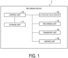
- a recording device 1 includes a control unit 10, a storage unit 11, an ultrasonic wave sensor 12, a recording unit 13, a transport unit 14, and an imaging unit 15.
- a configuration of the recording device 1 is described.
- the control unit 10 includes a Central Processing Unit (CPU) that collectively controls the respective units of the recording device 1, a Universal Asynchronous Receiver Transmitter (UART) that controls an input and an output, a logic circuit such as a Field Programmable Gate Array (FPGA) and a Programmable Logic Device (PLD), and the like.
- the CPU is also simply referred to as a processor.
- the storage unit 11 includes re-writable non-volatile memory such as a flash Read Only Memory (ROM) and a Hard Disk Drive (HDD), a volatile memory such as a Random Access Memory (RAM), and the like.
- the CPU of the control unit 10 reads a program such as firmware stored in the non-volatile memory of the storage unit 11, and executes the program by using the RAM of the storage unit 11 as a working region.
- a medium M illustrated in FIG. 2 is an elongated fiber formed of natural fibers or synthetic fibers, and an ultrasonic wave can pass the medium M.
- the elongated fiber is also referred to as an original fabric.
- the recording device 1 performs recording on the medium M. Recording on a fiber is also referred to as textile printing, and the medium M is also referred to as a textile-printed material.
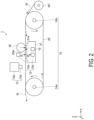
- the transport unit 14 includes an endless transporting belt 20, a driving roller 14a being a first roller, and a driven roller 14b being a second roller.
- the transporting belt 20 is stretched over the driving roller 14a and the driven roller 14b.
- the transport unit 14 rotates the driving roller 14a in a counterclockwise direction by a transport motor, which is not illustrated. Along with this, the driven roller 14b is rotated in a counterclockwise direction.
- the transporting belt 20 stretched over the driving roller 14a and the driven roller 14b also revolves in a counterclockwise direction, that is a revolving direction. Note that a driving-driven relationship between the driving roller 14a and the driven roller 14b may be inverted.
- the medium M drawn from a roll body M1 wound in a roll shape is placed on the transporting belt 20 of the transport unit 14 and is transported, under control of the control unit 10.
- the recording device 1 includes the imaging unit 15 and a reception unit 12b of the ultrasonic wave sensor 12, which is described later, at positions below the transporting belt 20 on which the medium M is placed.
- the recording device 1 includes the recording unit 13 and a transmission unit 12a of the ultrasonic wave sensor 12, which is described later, at positions above the transporting belt 20 on which the medium M is placed. Note that a positional relationship between the transmission unit 12a and the reception unit 12b of the ultrasonic wave sensor 12 may be inverted.
- the imaging unit 15, the ultrasonic wave sensor 12, and the recording unit 13 are positioned between the driving roller 14a and the driven roller 14b.
- the imaging unit 15, the ultrasonic wave sensor 12, and the recording unit 13 are arranged in the stated order from upstream to downstream.
- An order opposite to the above-mentioned order corresponds to an order from downstream to upstream in the revolving direction of the transporting belt 20.
- the imaging unit 15 and the ultrasonic wave sensor 12 may be inverted in the order.
- a first opening portion 20a being an opening and a first opening is provided in the transporting belt 20 in the up-and-down direction being a thickness direction at a predetermined interval along the revolving direction of the transporting belt 20.
- An ultrasonic wave of the ultrasonic wave sensor 12 can pass through the first opening portion 20a.
- the imaging unit 15 is capable of capturing an image of the medium M from below through the first opening portion 20a.
- the support portion 20b of the transporting belt 20 illustrated in FIG. 3 and FIG. 4 is a portion that does not have the first opening portion 20a and is a portion capable of supporting the medium M placed thereon.
- a glue being an adhesive having adhesiveness is provided on the front surface of the support portion 20b of the transporting belt 20, and is capable of attracting the medium M.
- the glue includes a silicone resin, for example.
- An electrification device that electrifies the front surface of the support portion 20b of the transporting belt 20 may be provided.
- This is a so-called electrostatic belt that electrifies the front surface of the support portion 20b. With this, the medium M can be attracted. Note that, in the recording device 1, at least either of the glue or the electrification device is provided to the support portion 20b.
- the transporting belt 20 is capable of attracting the medium M and transporting the medium M in a stabilized manner. As a result, accuracy of imagining performed by the imaging unit 15 and detection performed by the ultrasonic wave sensor 12 can be improved.
- the recording unit 13 includes an ink-jet type head 13a and a carriage 13b.
- the recording unit 13 is provided at a position facing the transporting belt 20 on which the medium M is placed.
- the carriage 13b includes a carriage motor.
- An ink cartridge or an ink tank can be mounted to the recording device 1.
- the ink cartridge or the ink tank stores ink of respective colors including Cyan, Magenta, Yellow, and Black (C, M, Y, and K) being ink colors, for example.
- the recording unit 13 includes a supply mechanism that supplies ink from the ink cartridge or the like to the head.
- the supply mechanism supplies ink of the respective colors from the ink cartridge or the like to the corresponding nozzles of the head 13a.
- the head 13a is mounted to the carriage 13b and is driven by the carriage motor to reciprocate above the medium M in the front-and-rear direction together with the carriage 13b.
- the head 13a is capable of performing recording by ejecting an ink droplet being a liquid from a nozzle onto the medium M while moving above the medium M under control of the control unit 10 based on recorded data.
- the recorded data is stored in the storage unit 11.
- the recorded data may be read from a storage medium by a reading unit included in the storage unit 11 or may be acquired from an external device.
- the ink colors may include, for example gradations of C, M, Y, and K, and hence may include any combination of four or more colors.
- the head 13a may include a nozzle that ejects a penetrant liquid onto the medium M.
- the penetrant liquid is a liquid that promotes penetration of an ink droplet, which adheres to the front surface of the medium M, to the back surface thereof.
- the ultrasonic wave sensor 12 includes the transmission unit 12a being a transmitter that transmits a transmission wave S and the reception unit 12b being a receiver that receives a reception wave R.
- the ultrasonic wave sensor 12 uses an ultrasonic wave from 30 kHz to 10 MHz, for example.
- the transmission unit 12a and the reception unit 12b of the ultrasonic wave sensor 12 are arranged above the transporting belt 20 and below the transporting belt 20, respectively, so as to sandwich the transporting belt 20 on which the medium M is placed.
- the ultrasonic wave sensor 12 is a so-called transmissive sensor in which the transmission unit 12a transmits the transmission wave S to the medium M and the reception unit 12b receives the reception wave R having passed through the medium M.
- An ultrasonic wave of the ultrasonic wave sensor 12 can pass through the first opening portion 20a of the transporting belt 20. Specifically, the transmission unit 12a and the reception unit 12b are positioned sandwiching the medium M via the first opening portion 20a.
- the imaging unit 15 is formed of a camera including a solid imaging element such as a Charge Coupled Device (CCD) image sensor.
- the imaging unit 15 may include an illumination unit that irradiates the medium M with illumination light.
- the imaging unit 15 is capable of capturing an image of the medium M from below through the first opening portion 20a of the transporting belt 20.
- CCD Charge Coupled Device
- a pressing unit 30 presses a part of the medium M placed and supported on the support portion 20b of the transporting belt 20, against the transporting belt 20.
- the pressed part of the medium M is upstream of the recording unit 13 in the revolving direction of the transporting belt 20.
- the pressing unit 30 is a pressure roller, for example.
- the pressing unit 30 may be reciprocable in a transport direction of the medium M and an opposite transport direction being a direction opposite to the transport direction.
- a supporting member 31 is provided at a position facing the pressing unit 30 across the transporting belt 20.
- the supporting member 31 supports the transporting belt 20 by sandwiching the transporting belt 20 together with the pressing unit 30.
- the supporting member 31 is a so-called platen for bearing a load from the pressing unit 30.
- the imaging unit 15 is capable of capturing an image of the medium M having passed through the position of the pressing unit 30, and the ultrasonic wave sensor 12 is capable of detecting the medium M having passed through the position of the pressing unit 30.
- the medium M is sandwiched between the pressing unit 30 and the supporting member 31, is brought into closer contact with the transporting belt 20, and hence is transported in a more stabilized manner.
- accuracy of imagining performed by the imaging unit 15 and detection performed by the ultrasonic wave sensor 12 with respect to the medium M can further be improved.
- the supporting member 31 is capable of accommodating the imaging unit 15 and the reception unit 12b of the ultrasonic wave sensor 12 inside.
- the imaging unit 15 and the ultrasonic wave sensor 12 are accommodated in the supporting member 31, so that an influence of an external environment where the recording device 1 is installed, such as ambient light and a noise can be suppressed.
- the supporting member 31 have both functions of supporting the transporting belt 20 and accommodating the imaging unit 15 and the ultrasonic wave sensor 12. With this, the recording device 1 can be reduced in size.
- a second opening portion 31a being a second opening that is opened toward the transporting belt 20 is provided in the supporting member 31.
- an opening part a part where the second opening portion 31a and the first opening portion 20a overlap with each other and are communicating with each other in the up-and-down direction is referred to as an opening part.
- the constituent members of the recording device 1, which block an ultrasonic wave or light, are not provided in the opening part, and hence an ultrasonic wave or light can pass therethrough. There can be obtained a state in which only the medium M is present in the opening part.
- the imaging unit 15 is capable of capturing an image of the medium M in an upward manner, the medium M being exposed from the opening part.
- the reception unit 12b of the ultrasonic wave sensor 12 is capable of receiving, as the reception wave R, an ultrasonic wave that is transmitted by the transmission unit 12a through the opening part, passes through the medium M, and enters from above.
- first opening portion 20a and the second opening portion 31a are communicating with each other may be determined by the control unit 10, based on a moving amount of the transporting belt 20.
- a sensor optical sensor or the like
- the control unit 10 may perform the determination based on a detection result from the sensor.
- the sensor may be a second reception unit that is provided to the same side as the transmission unit 12a with respect to the medium M, for example.
- the second reception unit is a receiver that receives the reception wave R and is different from the reception unit 12b.
- the ultrasonic wave sensor 12 is capable of detecting transmission of an ultrasonic wave with respect to the medium M through the first opening portion 20a of the transporting belt 20 and the second opening portion 31a of the supporting member 31.
- the imaging unit 15 is capable of capturing an image of a mesh of the medium M.
- the pressing unit 30 may be positioned above the imaging unit 15. In this case, the pressing unit 30 may be prevented from being present between the transmission unit 12a and the reception unit 12b. With this, for example, when the medium M has high translucency, degradation of imaging accuracy of the imaging unit 15, which is caused by excessive backlight, can be prevented. Moreover, transmission of an ultrasonic wave to the medium M is less hindered.
- the pressing unit 30 reciprocates in the transport direction of the medium M and the opposite transport direction, the pressing unit 30 may be positioned between the transmission unit 12a and the reception unit 12b along with the reciprocation motion.
- control unit 10 may control an operation of the recording unit 13, based on a reception result from the reception unit 12b at a timing when the pressing unit 30 is not present between the transmission unit 12a and the reception unit 12b due to the reciprocation motion.
- the recording device 1 may include a detection unit capable of detecting a position of the pressing unit 30 in the transport direction.
- control unit 10 is capable of controlling an operation of the recording unit 13, based on an imaging result from the imaging unit 15 and a detection result from the ultrasonic wave sensor 12.
- the control unit 10 causes the transport unit 14 to draw the medium M from the roll body M1 wound in a roll shape, place the medium M on the transporting belt 20 of the transport unit 14, and transport the medium M.
- the medium M is attracted on the transporting belt 20 due to the glue or the like provided on the front surface of the transporting belt 20. Further, the medium M is transported, is sandwiched between the pressing unit 30 and the supporting member 31, and is brought into close contact with the transporting belt 20.
- the second opening portion 31a is capable of communicating with the first opening portion 20a. There is obtained a state in which only the medium M is present in the opening part.
- control unit 10 causes the imaging unit 15 to capture an image of the medium M through the opening part and acquire imaging information being an imaging result.
- the control unit 10 subjects image processing such as edge detection to the acquired imaging information to extract a weave pattern of the fibers of the medium M.
- Weave patterns of the medium M and a plurality of pieces of weave information corresponding to the weave patterns are stored in the storage unit 11.
- the control unit 10 compares the weave pattern of the medium M extracted by the imaging unit 15, and the plurality of weave patterns stored in the storage unit 11 with each other.
- the control unit 10 specifies a weave pattern in the storage unit 11, which is closest to the extracted weave pattern, and acquires weave information corresponding to the specified weave pattern (S101).
- the weave information acquired by the control unit 10 includes information about a type of woven fabric, the information relating to density of the weave. As illustrated in FIG. 6 , the information indicating a type of woven fabric includes information indicating, for example, chiffon, lawn, or satin in the order from a loose weave to a close weave of the fibers of the medium M, for example.
- the control unit 10 causes the transmission unit 12a of the ultrasonic wave sensor 12 to transmit the transmission wave S to the medium M and causes the reception unit 12b to receive the reception wave R having passed through the medium M.
- a voltage of the reception wave R received by the reception unit 12b which is indicated with the vertical axis in FIG. 6 , is a detection result from the ultrasonic wave sensor 12, and indicates transmissivity information about an ultrasonic wave with respect to the medium M.
- the control unit 10 causes the reception unit 12b to acquire the transmissivity information about an ultrasonic wave with respect to the medium M (S102).
- Mesh information corresponds to the transmissivity information about an ultrasonic wave for each type of woven fabric.
- the mesh information corresponds to the voltage of the reception wave R received by the reception unit 12b, which is the transmissivity information about an ultrasonic wave, for each of woven fabric types such as chiffon, lawn, and satin.
- the voltage of the reception wave R received by the reception unit 12b corresponds to the mesh information being information relating to a so-called cotton yarn count indicating a size of the mesh of the medium M.
- FIG. 6 Those relationships are illustrated in FIG. 6 .
- the horizontal axis in FIG. 6 indicates the cotton yarn count. Note that the cotton yarn count has a smaller value for a larger mesh of the medium M, which indicates that the medium M is thick.
- the voltage of the reception wave R is increased.
- an ultrasonic wave tends to easily pass through the medium M.
- the dots in FIG. 6 indicate a value obtained by measuring the voltage of the reception wave R with respect to a size of the mesh of the medium M for each of woven fabric types such as chiffon, lawn, and satin.
- Curves T1, T2, and T3 are approximation curves calculated for chiffon, lawn, and satin, respectively, based on these dots.
- control unit 10 controls an operation of the recording unit 13.
- the storage unit 11 stores the relationships of these approximation curves.
- the control unit 10 acquires the weave information including the information about a type of woven fabric, based on the imaging information acquired by the imaging unit 15. Moreover, the control unit 10 acquires the mesh information indicating the size of the mesh of the medium M for each piece of the weave information.
- the mesh information corresponds to the transmissivity information about an ultrasonic wave being the voltage of the reception wave R received by the reception unit 12b.
- a degree of striking-through of ink differs depending on a type of woven fabric of the medium M.
- an ink ejection amount from the recording unit 13 is preferably reduced.
- the ink ejection amount is preferably increased.
- the smaller the size of the mesh of the medium M is, the less the medium M absorbs ink, leading the ink to tend to bleed.
- the smaller the size of the mesh of the medium M is, the more easily the ink bleeds.
- the ink ejection amount is preferably reduced.
- the control unit 10 is only required to acquire the mesh information about the medium M, which corresponds to the transmissivity information about an ultrasonic wave, for each piece of the weave information while referring to the recording unit 13, and to acquire the ink ejection amount corresponding to the mesh information.
- the mesh information corresponds to the transmissivity information about an ultrasonic wave. Therefore, the control unit 10 may acquire the ink ejection amount corresponding to the transmissivity information about an ultrasonic wave, through direct use of the transmissivity information about an ultrasonic wave instead of the mesh information, for each piece of the weave information.
- control unit 10 is capable of acquiring the ink ejection amount, based on the weave information and the transmissivity information (S103).
- the storage unit 11 stores the ink ejection amount for each of woven fabric types such as chiffon, lawn, and satin, which is indicated in the weave information.
- the ink ejection amount corresponds to the voltage of the reception wave R received by the reception unit 12b, which is the transmissivity information about an ultrasonic wave. Those relationships are illustrated in FIG. 7 .
- the ink ejection amount is indicated in pl/dot, that is, an ink amount per dot.
- the ink ejection amount illustrated in FIG. 7 indicates a total ink amount of each ink color with respect to the corresponding dot. Note that the ink ejection amount illustrated in FIG. 7 may be an ink amount of ink of one specific color or a plurality of colors with respect to the corresponding dot.
- the dots in FIG. 7 each indicate a value obtained by measuring the ink ejection amount appropriate for the voltage of the reception wave R received by the reception unit 12b, which is the transmissivity information about an ultrasonic wave, for each of woven fabric types of the medium M such as chiffon, lawn, and satin.
- the appropriate ink ejection amount is smaller than those of other woven fabrics.
- the voltage of the reception wave R received by the reception unit 12b is increased in the order of d1, d2, and d3, the size of the mesh of the medium M is smaller.
- the appropriate ink ejection amount is reduced in the order of k1, k2, and k3.
- the appropriate ink ejection amount is between that of chiffon and that of satin.
- the appropriate ink ejection amount is reduced in the order of j1, j2, and j3.
- the appropriate ink ejection amount is larger than those of other woven fabric.
- the voltage of the reception wave R received by the reception unit 12b is increased in the order of d1, d2, and d3, the size of the mesh of the medium M is smaller.
- the appropriate ink ejection amount is reduced in the order of i1, i2, and i3.
- Curves U1, U2, and U3 illustrated in FIG. 7 indicate approximation curves for chiffon, lawn, and satin, respectively, based on these dots.
- the control unit 10 controls an operation of the recording unit 13.
- the storage unit 11 stores the relationships of these approximation curves.
- the control unit 10 causes the recording unit 13 to perform recording on the medium M, based on the ink ejection amount acquired from the storage unit 11 (S104).
- the ink ejection amount is set to an appropriate amount based on the weave information about the medium M and the transmissivity information, and thus appropriate recording can be performed on the medium M.
- control unit 10 is capable of controlling an operation of the recording unit 13, based on the imaging information, which is an imaging result from the imaging unit 15, and the voltage of the reception wave R received by the reception unit 12b, which is a detection result from the ultrasonic wave sensor 12.
- control unit 10 sets the ink ejection amount appropriate for the medium M by controlling the head 13a of the recording unit 13.
- control unit 10 increase electric power of a driving waveform to be applied to the head 13a, thereby increasing the ink ejection amount.
- control unit 10 applies a driving waveform to the head 13a for a plurality of times to eject an ink droplet for a plurality of times. With this, the ink ejection amount can also be increased.
- the control unit 10 can also increase a velocity of an ink droplet by increasing a voltage of a driving waveform to be applied to the head 13a.
- the control unit 10 may increase a frequency of a driving waveform to increase the number of times for ejecting an ink droplet.
- the control unit 10 can also reduce a moving velocity of the carriage 13b to allow an ink droplet ejected to be easily absorbed by the medium M.
- the control unit 10 executes at least one of the above-mentioned controls with respect to the head 13a, based on the mesh information about the medium M, which corresponds to the transmissivity information obtained by the ultrasonic wave sensor 12, in addition to the weave information about the medium M, which corresponds to the imaging information obtained by the imaging unit 15. With this, the ink ejection amount appropriate for the medium M can be set, and appropriate recording can be performed.
- a recording device 2 according to a second exemplary embodiment is obtained by adding a measurement unit 32 and an adjustment unit 33 to the recording device 1 according to the first exemplary embodiment, which is illustrated in FIG. 1 , and changing the positions of the ultrasonic wave sensor 12 and the imaging unit 15. Note that the pressing unit 30 is eliminated.
- FIG. 9 a configuration of the recording device 2 is described. Note that, in the constituent elements of the recording device 2 illustrated in FIG. 8 and FIG. 9 , the same constituent elements as those of the recording device 1 illustrated in FIG. 1 are denoted with the same reference symbols.
- a holding unit 34 of the recording device 2 is capable of holding the roll body M1 obtained by winding the medium M in a roll shape.
- a shaft is provided at the center of the roll body M1, and the holding unit 34 holds the roll body M1 in a rotatable manner.
- the medium M is drawn out from the roll body M1 held by the holding unit 34 and is transported so as to arrive at the position at which the transporting belt 20 is stretched to the driven roller 14b of the transport unit 14, via the positions of the adjustment unit 33, the imaging unit 15, and the ultrasonic wave sensor 12.
- a portion of the medium M from the position of the holding unit 34 to the position of the transporting belt 20 is referred to as an adjustment portion M2.
- the adjustment unit 33 includes an adjustment roller 33a and a moving unit 33b.
- the adjustment roller 33a is brought into contact with the adjustment portion M2 while rotating, and thus is capable of applying a tension.
- the moving unit 33b includes a motor, and the motor of the moving unit 33b moves the position of the adjustment roller 33a with respect to the adjustment portion M2, under control of the control unit 10. With this, a tension of the adjustment portion M2 can be adjusted.
- the recording device 2 includes an accommodation unit 35 that has only an accommodation function, in place of the supporting member 31 of the recording device 1.
- the accommodation unit 35 is capable of accommodating the imaging unit 15 and the reception unit 12b of the ultrasonic wave sensor 12 inside.
- the accommodation unit 35 is provided between the position of the holding unit 34 and the position of the transporting belt 20.
- a third opening portion 35a which is opened toward the adjustment portion M2 of the medium M, is provided in the accommodation unit 35.
- the imaging unit 15 is capable of capturing an image of the adjustment portion M2 in an upward manner through the third opening portion 35a.
- the transmission unit 12a and the reception unit 12b of the ultrasonic wave sensor 12 are positioned sandwiching the adjustment portion M2.
- the reception unit 12b of the ultrasonic wave sensor 12 is capable of receiving, as the reception wave R, an ultrasonic wave that is transmitted by the transmission unit 12a through the third opening portion 35a, passes through the adjustment portion M2, and enters from above.
- the measurement unit 32 is provided upstream of the recording unit 13 in the transport direction of the medium M.
- a portion of the transporting belt 20 on which the medium M is placed and supported is referred to as the support portion 20b.
- the measurement unit 32 is capable of measuring a tension of the support portion 20b.
- the measurement unit 32 includes a measurement roller 32a and a tension measurement unit 32b.
- the measurement roller 32a is capable of moving to or from the support portion 20b in the up-and-down direction via the medium M while rotating.
- the tension measurement unit 32b includes a pressure sensor or a position detection sensor, and thus is capable of measuring a pressure received from the measurement roller 32a or a tension received from the support portion 20b by detecting a movement in the up-and-down direction.
- the tension measurement unit 32b is not particularly limited as long as a configuration capable of measuring a tension of the support portion 20b is provided.
- the control unit 10 acquires, from the measurement unit 32, a measurement result from measuring a tension of the support portion 20b of the transporting belt 20.
- the control unit 10 controls the adjustment unit 33 to perform adjustment so that a tension of the adjustment portion M2 of the medium M is equal to a tension of the support portion 20b, which is the measurement result.
- a tension of the support portion 20b of the transporting belt 20, which is measured by the measurement unit 32, is also a tension of the medium M on which the recording unit 13 performs recording.
- a tension of the adjustment portion M2 of the medium M is a tension at the position at which the imaging unit 15 performs imaging and the ultrasonic wave sensor 12 performs detection.
- the control unit 10 controls the measurement unit 32 and the adjustment unit 33.
- a tension of the medium M on which the recording unit 13 performs recording and a tension of the medium M at the position at which the imaging unit 15 performs imaging and the ultrasonic wave sensor 12 performs detection are substantially equal to each other.
- a tension measured by the measurement unit 32 may contain rigidity of the support portion 20b, and hence may tend to be higher than a tension of only the medium M at the positions of the imaging unit 15 and the ultrasonic wave sensor 12.
- the control unit 10 is only required to adjust the adjustment unit 33 so that a tension at the positions of the imaging unit 15 and the ultrasonic wave sensor 12 is lower than a tension measured by the measurement unit 32.
- a state such as a weave and a mesh of the adjustment portion M2 of the medium M can be set to substantially the same as a state such as a weave and a mesh of the medium M on the support portion 20b.
- the measurement unit 32 and the adjustment unit 33 are capable of causing a state of a tension of the adjustment portion M2 of the medium M to match with a state of a tension of the medium M at the position of the recording unit 13. Therefore, even when the imaging unit 15 performs imaging and the ultrasonic wave sensor 12 performs detection at a position different from the support portion 20b, that is, at the adjustment portion M2, degradation of accuracy of the imaging and detection can be suppressed. In particular, accuracy of the weave information about the medium M, which is acquired by the imaging unit 15, and accuracy of the mesh information about the medium M, which is acquired by the reception unit 12b, can be improved.
- the control unit 10 improves accuracy of the mesh information about the medium M, which corresponds to the transmissivity information obtained by the ultrasonic wave sensor 12, as well as accuracy of the weave information about the medium M, which corresponds to the imaging information obtained by the imaging unit 15. Moreover, the ink ejection amount appropriate for the medium M can be set based on the weave information and the mesh information. With this, appropriate recording can be performed.
- the imaging unit 15 performs imaging and the ultrasonic wave sensor 12 performs detection at the adjustment portion M2 of the medium M, which is not placed on the transporting belt 20. Therefore, the recording device 2 does not require the first opening portion 20a provided to the transporting belt 20, which is different from the recording device 1 according to the first exemplary embodiment.
- the recording devices 1 and 2 are capable of acquiring the ink ejection amount appropriate for the medium M, based on the weave information about the medium M, which corresponds to the imaging information obtained by the imaging unit 15, and the mesh information about the medium M, which corresponds to the transmissivity information obtained by the ultrasonic wave sensor 12. With this, appropriate recording can be performed.
- the recording unit 13 of the recording devices 1 and 2 is described as a serial type in which the head 13a is mounted to the carriage 13b and moves.
- the recording unit 13 may be a line type in which the head 13a is fixed without the carriage 13b.
- the types of woven fabric of the medium M may be other than chiffon, lawn, and satin.
- the transport unit 14 may include a feeding device at a position near the driven roller 14b. The feeding device draws the medium M out from the roll body M1.
- the transport unit 14 may include a winding device at a position near the driving roller 14a. The winding device winds the medium M peeled off the transporting belt 20.
- the recording devices 1 and 2 may include a cleaning device that cleans, with a cleaning liquid, the transporting belt 20 after the medium M on which recording has been performed is peeled off, a wiping device that wipes the cleaning liquid adhering to the transporting belt 20, a drying device that dries the cleaning liquid adhering to the transporting belt 20, an applying device that applies the glue on the transporting belt 20, or the like.
- the recording device 1 includes the recording unit 13 configured to perform recording by ejecting a liquid onto the medium M configured to transmit an ultrasonic wave, the transport unit 14 configured to transport the medium M, the imaging unit 15 configured to capture an image of the medium M, the ultrasonic wave sensor 12 including the transmission unit 12a configured to transmit an ultrasonic wave to the medium M and the reception unit 12b configured to receive an ultrasonic wave transmitted by the transmission unit 12a, and the control unit 10 configured to control an operation of the recording unit 13, based on an imaging result from the imaging unit 15 and a detection result from the ultrasonic wave sensor 12.
- the transmission unit 12a and the reception unit 12b are positioned sandwiching the medium M.
- the recording device 1 is capable of detecting a thickness of the medium M, based on intensity of an ultrasonic wave received by the reception unit 12b.
- the control unit 10 is capable of controlling an operation of the recording unit 13 based on the information acquired by the ultrasonic wave sensor 12, that is, the information about the thickness of the medium M, as well as the information acquired by the imaging unit 15, that is, the information about the state of front surface of the medium M.
- An operation of the recording unit 13 includes, for example increasing a driving waveform voltage, which corresponds to a velocity of an ink droplet, for a thick medium M, increasing a frequency of a driving waveform, which corresponds to the number of times for ejecting ink, for a thick medium M, reducing a carriage velocity, which corresponds to quickness of ink to be absorbed, for a thick medium M, and the like.
- the recording device 1 is capable of controlling an ejection amount of an ink droplet, and thus an appropriate image in accordance with the medium M can be obtained.
- the transport unit 14 includes the transporting belt 20 having an endless shape, and the driving roller 14a and the driven roller 14b over which the transporting belt 20 is stretched, the recording unit 13 faces the transporting belt 20 stretched over the driving roller 14a and the driven roller 14b, the transporting belt 20 has the first opening portion 20a being an opening through which an ultrasonic wave transmitted by the transmission unit 12a is configured to pass, when a portion of the transporting belt 20 that does not have the first opening portion 20a and supports the medium M is regarded as the support portion 20b, the support portion 20b is configured to attract the medium M, and the ultrasonic wave sensor 12 and the imaging unit 15 are positioned between the driving roller 14a and the driven roller 14b.
- the recording device 1 is capable of acquiring an imaging result from the imaging unit 15 and a detection result from the ultrasonic wave sensor 12 under a tension condition close to the tension condition at the time of performing recording on the medium M by the recording unit 13. With this, control of a recording operation can be performed at higher accuracy.
- the recording device 1 described above further includes the pressing unit 30 configured to press, against the transporting belt 20, a part of the medium M supported on the support portion 20b, the part being present upstream of the recording unit 13 in the revolving direction of the transporting belt 20, wherein the imaging unit 15 is configured to capture an image of the medium M after passing through the pressing unit 30, and the ultrasonic wave sensor 12 is configured to detect the medium M after passing through the pressing unit 30.
- the pressing unit 30 configured to press, against the transporting belt 20, a part of the medium M supported on the support portion 20b, the part being present upstream of the recording unit 13 in the revolving direction of the transporting belt 20, wherein the imaging unit 15 is configured to capture an image of the medium M after passing through the pressing unit 30, and the ultrasonic wave sensor 12 is configured to detect the medium M after passing through the pressing unit 30.
- the recording device 1 can further improve accuracy of an imaging result from the imaging unit 15 and an imaging and detection result from the ultrasonic wave sensor 12.
- the recording device 1 described above further includes the supporting member 31 configured to support the transporting belt 20 by sandwiching the transporting belt 20 together with the pressing unit 30, wherein the supporting member 31 has the second opening portion 31a configured to be in communication with the first opening portion 20a, the imaging unit 15 and the reception unit 12b are accommodated in the supporting member 31, the imaging unit 15 is configured to capture an image of the medium M exposed from the first opening portion 20a and the second opening portion 31a, and the reception unit 12b receives an ultrasonic wave passed through the first opening portion 20a and the second opening portion 31a.
- the supporting member 31 accommodates the imaging unit 15 and the reception unit 12b inside.
- the supporting member 31 also functions as an accommodation means that accommodates the imaging unit 15 and the reception unit 12b, and hence the recording device 1 can be reduced in size.
- the transport unit 14 includes the transporting belt 20 having an endless shape
- the recording device 2 further includes the adjustment unit 33 configured to adjust a tension of the adjustment portion M2 when a portion of the medium M from the holding unit 34 to the transporting belt 20 is regarded as the adjustment portion M2, the holding unit 34 being configured to hold the roll body M1 around which the medium M is wound, and the measurement unit 32 configured to measure a tension of the support portion 20b when a portion of the transporting belt 20 supporting the medium M is regarded as the support portion 20b
- the control unit 10 controls the adjustment unit 33 based on a measurement result from the measurement unit 32 so that a tension of the adjustment portion M2 corresponds to a tension of the support portion 20b
- the imaging unit 15 is configured to capture an image of the adjustment portion M2, and the transmission unit 12a and the reception unit 12b are positioned sandwiching the adjustment portion M2.
- the recording device 2 is capable of creating a state of enabling the imaging unit 15 to perform imagining under a tension condition close to the tension condition at the time of performing recording on the medium M by the recording unit 13, without processing such as providing an opening in the transporting belt 20.
- the recording device 2 further includes the accommodation unit 35 configured to accommodate the imaging unit 15 and the reception unit 12b.
- the recording device 2 is capable of suppressing an influence of an external environment where the recording device 2 is installed.
Landscapes
- Engineering & Computer Science (AREA)
- Textile Engineering (AREA)
- Ink Jet (AREA)
- Controlling Sheets Or Webs (AREA)
Abstract
Description
- The present application is based on, and claims priority from
JP Application Serial Number 2021-150052, filed September 15, 2021 - The present disclosure relates to a recording device.
- Hitherto, there has been known a device that captures an image of fabric with a camera or the like and performs printing as described in
JP-A-2021-84359 - However, the device described in
JP-A-2021-84359 - A recording device includes a recording unit configured to perform recording by ejecting a liquid onto a medium configured to transmit an ultrasonic wave, a transport unit configured to transport the medium, an imaging unit configured to capture an image of the medium, an ultrasonic wave sensor including a transmission unit configured to transmit an ultrasonic wave to the medium and a reception unit configured to receive an ultrasonic wave transmitted by the transmission unit, and a control unit configured to control an operation of the recording unit, based on an imaging result from the imaging unit and a detection result from the ultrasonic wave sensor, wherein the transmission unit and the reception unit are positioned sandwiching the medium.
-
-
FIG. 1 is a block diagram illustrating a configuration of a recording device according to a first exemplary embodiment. -
FIG. 2 is a schematic diagram illustrating the configuration of the recording device according to the first exemplary embodiment. -
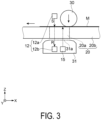
FIG. 3 is a schematic diagram illustrating a part corresponding to an ultrasonic wave sensor and an imaging unit inFIG. 2 , in an enlarged manner. -
FIG. 4 is a schematic diagram obtained by viewingFIG. 3 in a direction from a recording unit. -
FIG. 5 is a flowchart illustrating one example of a control method of a control unit. -
FIG. 6 is a diagram illustrating an example of a relationship between a type of woven fabric of a medium, transmissivity information about an ultrasonic wave, and mesh information. -
FIG. 7 is a characteristic diagram illustrating an example of a relationship between a type of woven fabric of a medium, transmissivity information about an ultrasonic wave, and an ink ejection amount. -
FIG. 8 is a block diagram illustrating a configuration of a recording device according to a second exemplary embodiment. -
FIG. 9 is a schematic diagram illustrating the configuration of the recording device according to the second exemplary embodiment. - Exemplary embodiments are described below with reference to the accompanying figures. Note that the directions in the drawings are described through use of a three-dimensional coordinate system in which an X axis, a Y axis, and a Z axis are orthogonal to one another. Herein, it is assumed that a direction extending along the X axis, a direction extending along the Y axis, and a direction extending along the Z axis are an X direction, a Y direction, and a Z direction, respectively. For convenience of description, a positive direction of the Z direction is referred to as an upward direction or simply as upward and a negative direction thereof is referred to as a downward direction or simply as downward, a positive direction of the X direction is referred to as a rightward direction or simply as rightward and a negative direction thereof is referred to as a leftward direction or simply as leftward, and a positive direction of the Y direction is referred to as a frontward direction or simply as frontward and a negative direction thereof is referred to as a rearward direction or simply as rearward.
- As illustrated in
FIG. 1 , arecording device 1 according to a first exemplary embodiment includes acontrol unit 10, astorage unit 11, anultrasonic wave sensor 12, arecording unit 13, atransport unit 14, and animaging unit 15. With reference also toFIG. 2 , a configuration of therecording device 1 is described. - The
control unit 10 includes a Central Processing Unit (CPU) that collectively controls the respective units of therecording device 1, a Universal Asynchronous Receiver Transmitter (UART) that controls an input and an output, a logic circuit such as a Field Programmable Gate Array (FPGA) and a Programmable Logic Device (PLD), and the like. The CPU is also simply referred to as a processor. Thestorage unit 11 includes re-writable non-volatile memory such as a flash Read Only Memory (ROM) and a Hard Disk Drive (HDD), a volatile memory such as a Random Access Memory (RAM), and the like. - The CPU of the
control unit 10 reads a program such as firmware stored in the non-volatile memory of thestorage unit 11, and executes the program by using the RAM of thestorage unit 11 as a working region. - As an example, a medium M illustrated in
FIG. 2 is an elongated fiber formed of natural fibers or synthetic fibers, and an ultrasonic wave can pass the medium M. The elongated fiber is also referred to as an original fabric. Therecording device 1 performs recording on the medium M. Recording on a fiber is also referred to as textile printing, and the medium M is also referred to as a textile-printed material. - As illustrated in
FIG. 2 , thetransport unit 14 includes anendless transporting belt 20, adriving roller 14a being a first roller, and a drivenroller 14b being a second roller. Thetransporting belt 20 is stretched over thedriving roller 14a and the drivenroller 14b. - The
transport unit 14 rotates thedriving roller 14a in a counterclockwise direction by a transport motor, which is not illustrated. Along with this, the drivenroller 14b is rotated in a counterclockwise direction. Thetransporting belt 20 stretched over thedriving roller 14a and the drivenroller 14b also revolves in a counterclockwise direction, that is a revolving direction. Note that a driving-driven relationship between thedriving roller 14a and the drivenroller 14b may be inverted. - The medium M drawn from a roll body M1 wound in a roll shape is placed on the
transporting belt 20 of thetransport unit 14 and is transported, under control of thecontrol unit 10. - As illustrated in
FIG. 2 andFIG. 3 , therecording device 1 includes theimaging unit 15 and areception unit 12b of theultrasonic wave sensor 12, which is described later, at positions below thetransporting belt 20 on which the medium M is placed. Therecording device 1 includes therecording unit 13 and atransmission unit 12a of theultrasonic wave sensor 12, which is described later, at positions above thetransporting belt 20 on which the medium M is placed. Note that a positional relationship between thetransmission unit 12a and thereception unit 12b of theultrasonic wave sensor 12 may be inverted. - The
imaging unit 15, theultrasonic wave sensor 12, and therecording unit 13 are positioned between thedriving roller 14a and the drivenroller 14b. - In the revolving direction of the
transporting belt 20 with the position of the drivenroller 14b as a reference, theimaging unit 15, theultrasonic wave sensor 12, and therecording unit 13 are arranged in the stated order from upstream to downstream. An order opposite to the above-mentioned order corresponds to an order from downstream to upstream in the revolving direction of thetransporting belt 20. Note that theimaging unit 15 and theultrasonic wave sensor 12 may be inverted in the order. - As illustrated in
FIG. 2 ,FIG. 3 , andFIG. 4 , a first openingportion 20a being an opening and a first opening is provided in thetransporting belt 20 in the up-and-down direction being a thickness direction at a predetermined interval along the revolving direction of thetransporting belt 20. - An ultrasonic wave of the
ultrasonic wave sensor 12 can pass through thefirst opening portion 20a. Theimaging unit 15 is capable of capturing an image of the medium M from below through thefirst opening portion 20a. - Note that the
support portion 20b of thetransporting belt 20 illustrated inFIG. 3 andFIG. 4 is a portion that does not have thefirst opening portion 20a and is a portion capable of supporting the medium M placed thereon. - A glue being an adhesive having adhesiveness is provided on the front surface of the
support portion 20b of thetransporting belt 20, and is capable of attracting the medium M. The glue includes a silicone resin, for example. - An electrification device that electrifies the front surface of the
support portion 20b of thetransporting belt 20 may be provided. This is a so-called electrostatic belt that electrifies the front surface of thesupport portion 20b. With this, the medium M can be attracted. Note that, in therecording device 1, at least either of the glue or the electrification device is provided to thesupport portion 20b. - With this configuration, the
transporting belt 20 is capable of attracting the medium M and transporting the medium M in a stabilized manner. As a result, accuracy of imagining performed by theimaging unit 15 and detection performed by theultrasonic wave sensor 12 can be improved. - As illustrated in
FIG. 2 , therecording unit 13 includes an ink-jet type head 13a and acarriage 13b. Therecording unit 13 is provided at a position facing thetransporting belt 20 on which the medium M is placed. - The
carriage 13b includes a carriage motor. An ink cartridge or an ink tank can be mounted to therecording device 1. The ink cartridge or the ink tank stores ink of respective colors including Cyan, Magenta, Yellow, and Black (C, M, Y, and K) being ink colors, for example. - The
recording unit 13 includes a supply mechanism that supplies ink from the ink cartridge or the like to the head. The supply mechanism supplies ink of the respective colors from the ink cartridge or the like to the corresponding nozzles of thehead 13a. - The
head 13a is mounted to thecarriage 13b and is driven by the carriage motor to reciprocate above the medium M in the front-and-rear direction together with thecarriage 13b. Thehead 13a is capable of performing recording by ejecting an ink droplet being a liquid from a nozzle onto the medium M while moving above the medium M under control of thecontrol unit 10 based on recorded data. The recorded data is stored in thestorage unit 11. The recorded data may be read from a storage medium by a reading unit included in thestorage unit 11 or may be acquired from an external device. - Note that the ink colors may include, for example gradations of C, M, Y, and K, and hence may include any combination of four or more colors.
- The
head 13a may include a nozzle that ejects a penetrant liquid onto the medium M. The penetrant liquid is a liquid that promotes penetration of an ink droplet, which adheres to the front surface of the medium M, to the back surface thereof. - As illustrated in
FIG. 2 andFIG. 3 , theultrasonic wave sensor 12 includes thetransmission unit 12a being a transmitter that transmits a transmission wave S and thereception unit 12b being a receiver that receives a reception wave R. Theultrasonic wave sensor 12 uses an ultrasonic wave from 30 kHz to 10 MHz, for example. - The
transmission unit 12a and thereception unit 12b of theultrasonic wave sensor 12 are arranged above the transportingbelt 20 and below the transportingbelt 20, respectively, so as to sandwich the transportingbelt 20 on which the medium M is placed. Theultrasonic wave sensor 12 is a so-called transmissive sensor in which thetransmission unit 12a transmits the transmission wave S to the medium M and thereception unit 12b receives the reception wave R having passed through the medium M. - An ultrasonic wave of the
ultrasonic wave sensor 12 can pass through thefirst opening portion 20a of the transportingbelt 20. Specifically, thetransmission unit 12a and thereception unit 12b are positioned sandwiching the medium M via thefirst opening portion 20a. - The
imaging unit 15 is formed of a camera including a solid imaging element such as a Charge Coupled Device (CCD) image sensor. Theimaging unit 15 may include an illumination unit that irradiates the medium M with illumination light. Theimaging unit 15 is capable of capturing an image of the medium M from below through thefirst opening portion 20a of the transportingbelt 20. - As illustrated in
FIG. 2 , apressing unit 30 presses a part of the medium M placed and supported on thesupport portion 20b of the transportingbelt 20, against the transportingbelt 20. The pressed part of the medium M is upstream of therecording unit 13 in the revolving direction of the transportingbelt 20. Thepressing unit 30 is a pressure roller, for example. Thepressing unit 30 may be reciprocable in a transport direction of the medium M and an opposite transport direction being a direction opposite to the transport direction. - A supporting
member 31 is provided at a position facing thepressing unit 30 across the transportingbelt 20. The supportingmember 31 supports the transportingbelt 20 by sandwiching the transportingbelt 20 together with thepressing unit 30. The supportingmember 31 is a so-called platen for bearing a load from thepressing unit 30. - The
imaging unit 15 is capable of capturing an image of the medium M having passed through the position of thepressing unit 30, and theultrasonic wave sensor 12 is capable of detecting the medium M having passed through the position of thepressing unit 30. - The medium M is sandwiched between the
pressing unit 30 and the supportingmember 31, is brought into closer contact with the transportingbelt 20, and hence is transported in a more stabilized manner. As a result, accuracy of imagining performed by theimaging unit 15 and detection performed by theultrasonic wave sensor 12 with respect to the medium M can further be improved. - As illustrated in
FIG. 2 andFIG. 3 , the supportingmember 31 is capable of accommodating theimaging unit 15 and thereception unit 12b of theultrasonic wave sensor 12 inside. - The
imaging unit 15 and theultrasonic wave sensor 12 are accommodated in the supportingmember 31, so that an influence of an external environment where therecording device 1 is installed, such as ambient light and a noise can be suppressed. The supportingmember 31 have both functions of supporting the transportingbelt 20 and accommodating theimaging unit 15 and theultrasonic wave sensor 12. With this, therecording device 1 can be reduced in size. - A
second opening portion 31a being a second opening that is opened toward the transportingbelt 20 is provided in the supportingmember 31. - As illustrated in
FIG. 3 andFIG. 4 , when, along with the move of the transportingbelt 20, the position of thefirst opening portion 20a of the transportingbelt 20 is moved to overlap with the position of thesecond opening portion 31a of the supportingmember 31, thesecond opening portion 31a and thefirst opening portion 20a are communicable with each other in the up-and-down direction. Note that, inFIG. 4 , illustration is given without the medium M. - In the following description, a part where the
second opening portion 31a and thefirst opening portion 20a overlap with each other and are communicating with each other in the up-and-down direction is referred to as an opening part. The constituent members of therecording device 1, which block an ultrasonic wave or light, are not provided in the opening part, and hence an ultrasonic wave or light can pass therethrough. There can be obtained a state in which only the medium M is present in the opening part. - When the medium M is placed on the transporting
belt 20, and thefirst opening portion 20a and thesecond opening portion 31a are communicating with each other, theimaging unit 15 is capable of capturing an image of the medium M in an upward manner, the medium M being exposed from the opening part. - Simultaneously, the
reception unit 12b of theultrasonic wave sensor 12 is capable of receiving, as the reception wave R, an ultrasonic wave that is transmitted by thetransmission unit 12a through the opening part, passes through the medium M, and enters from above. - Note that whether the
first opening portion 20a and thesecond opening portion 31a are communicating with each other may be determined by thecontrol unit 10, based on a moving amount of the transportingbelt 20. Alternatively, a sensor (optical sensor or the like) that is different from theultrasonic wave sensor 12 and theimaging unit 15 may be additionally arranged, and thecontrol unit 10 may perform the determination based on a detection result from the sensor. The sensor may be a second reception unit that is provided to the same side as thetransmission unit 12a with respect to the medium M, for example. The second reception unit is a receiver that receives the reception wave R and is different from thereception unit 12b. - As described above, for example, the
ultrasonic wave sensor 12 is capable of detecting transmission of an ultrasonic wave with respect to the medium M through thefirst opening portion 20a of the transportingbelt 20 and thesecond opening portion 31a of the supportingmember 31. For example, theimaging unit 15 is capable of capturing an image of a mesh of the medium M. - Note that, when the
imaging unit 15 includes the illumination unit, thepressing unit 30 may be positioned above theimaging unit 15. In this case, thepressing unit 30 may be prevented from being present between thetransmission unit 12a and thereception unit 12b. With this, for example, when the medium M has high translucency, degradation of imaging accuracy of theimaging unit 15, which is caused by excessive backlight, can be prevented. Moreover, transmission of an ultrasonic wave to the medium M is less hindered. When thepressing unit 30 reciprocates in the transport direction of the medium M and the opposite transport direction, thepressing unit 30 may be positioned between thetransmission unit 12a and thereception unit 12b along with the reciprocation motion. In this case, thecontrol unit 10 may control an operation of therecording unit 13, based on a reception result from thereception unit 12b at a timing when thepressing unit 30 is not present between thetransmission unit 12a and thereception unit 12b due to the reciprocation motion. In order to perform the above-mentioned control, therecording device 1 may include a detection unit capable of detecting a position of thepressing unit 30 in the transport direction. - As described later, the
control unit 10 is capable of controlling an operation of therecording unit 13, based on an imaging result from theimaging unit 15 and a detection result from theultrasonic wave sensor 12. - With reference mainly to the flowchart in
FIG. 5 as well as reference toFIG. 6 andFIG. 7 , a control method for therecording device 1 is described. - The
control unit 10 causes thetransport unit 14 to draw the medium M from the roll body M1 wound in a roll shape, place the medium M on the transportingbelt 20 of thetransport unit 14, and transport the medium M. - The medium M is attracted on the transporting
belt 20 due to the glue or the like provided on the front surface of the transportingbelt 20. Further, the medium M is transported, is sandwiched between thepressing unit 30 and the supportingmember 31, and is brought into close contact with the transportingbelt 20. - When, along with the move of the transporting
belt 20 by thetransport unit 14, the position of thefirst opening portion 20a of the transportingbelt 20 arrives at the position of thesecond opening portion 31a of the supportingmember 31 and overlaps therewith, thesecond opening portion 31a is capable of communicating with thefirst opening portion 20a. There is obtained a state in which only the medium M is present in the opening part. - When the
first opening portion 20a and thesecond opening portion 31a are communicating with each other, thecontrol unit 10 causes theimaging unit 15 to capture an image of the medium M through the opening part and acquire imaging information being an imaging result. - The
control unit 10 subjects image processing such as edge detection to the acquired imaging information to extract a weave pattern of the fibers of the medium M. - Weave patterns of the medium M and a plurality of pieces of weave information corresponding to the weave patterns are stored in the
storage unit 11. Thecontrol unit 10 compares the weave pattern of the medium M extracted by theimaging unit 15, and the plurality of weave patterns stored in thestorage unit 11 with each other. Thecontrol unit 10 specifies a weave pattern in thestorage unit 11, which is closest to the extracted weave pattern, and acquires weave information corresponding to the specified weave pattern (S101). - The weave information acquired by the
control unit 10 includes information about a type of woven fabric, the information relating to density of the weave. As illustrated inFIG. 6 , the information indicating a type of woven fabric includes information indicating, for example, chiffon, lawn, or satin in the order from a loose weave to a close weave of the fibers of the medium M, for example. - When the
first opening portion 20a and thesecond opening portion 31a are communicating with each other, thecontrol unit 10 causes thetransmission unit 12a of theultrasonic wave sensor 12 to transmit the transmission wave S to the medium M and causes thereception unit 12b to receive the reception wave R having passed through the medium M. - A voltage of the reception wave R received by the
reception unit 12b, which is indicated with the vertical axis inFIG. 6 , is a detection result from theultrasonic wave sensor 12, and indicates transmissivity information about an ultrasonic wave with respect to the medium M. Thecontrol unit 10 causes thereception unit 12b to acquire the transmissivity information about an ultrasonic wave with respect to the medium M (S102). - Mesh information corresponds to the transmissivity information about an ultrasonic wave for each type of woven fabric. Specifically, the mesh information corresponds to the voltage of the reception wave R received by the
reception unit 12b, which is the transmissivity information about an ultrasonic wave, for each of woven fabric types such as chiffon, lawn, and satin. The voltage of the reception wave R received by thereception unit 12b corresponds to the mesh information being information relating to a so-called cotton yarn count indicating a size of the mesh of the medium M. - Those relationships are illustrated in
FIG. 6 . The horizontal axis inFIG. 6 indicates the cotton yarn count. Note that the cotton yarn count has a smaller value for a larger mesh of the medium M, which indicates that the medium M is thick. - As illustrated in
FIG. 6 , when the medium M has a looser weave as in the case of chiffon, or has a smaller mesh and a larger cotton yarn count, the voltage of the reception wave R is increased. Thus, an ultrasonic wave tends to easily pass through the medium M. The dots inFIG. 6 indicate a value obtained by measuring the voltage of the reception wave R with respect to a size of the mesh of the medium M for each of woven fabric types such as chiffon, lawn, and satin. Curves T1, T2, and T3 are approximation curves calculated for chiffon, lawn, and satin, respectively, based on these dots. - Through use of the relationships of these approximation curves, the
control unit 10 controls an operation of therecording unit 13. Thestorage unit 11 stores the relationships of these approximation curves. - As described above, when the position of the
first opening portion 20a of the transportingbelt 20 overlaps and is communicating with the position of thesecond opening portion 31a of the supportingmember 31, thecontrol unit 10 acquires the weave information including the information about a type of woven fabric, based on the imaging information acquired by theimaging unit 15. Moreover, thecontrol unit 10 acquires the mesh information indicating the size of the mesh of the medium M for each piece of the weave information. The mesh information corresponds to the transmissivity information about an ultrasonic wave being the voltage of the reception wave R received by thereception unit 12b. - Meanwhile, a degree of striking-through of ink differs depending on a type of woven fabric of the medium M. The looser the weave is, the more likely it is for the striking-through of ink to occur. Thus, an ink ejection amount from the
recording unit 13 is preferably reduced. - The larger the size of the mesh of the medium M is, the thicker the medium M is, and the more the medium M tends to absorb ink. Thus, the ink ejection amount is preferably increased. Meanwhile, the smaller the size of the mesh of the medium M is, the less the medium M absorbs ink, leading the ink to tend to bleed. The smaller the size of the mesh of the medium M is, the more easily the ink bleeds. Thus, the ink ejection amount is preferably reduced.
- The
control unit 10 is only required to acquire the mesh information about the medium M, which corresponds to the transmissivity information about an ultrasonic wave, for each piece of the weave information while referring to therecording unit 13, and to acquire the ink ejection amount corresponding to the mesh information. - The mesh information corresponds to the transmissivity information about an ultrasonic wave. Therefore, the
control unit 10 may acquire the ink ejection amount corresponding to the transmissivity information about an ultrasonic wave, through direct use of the transmissivity information about an ultrasonic wave instead of the mesh information, for each piece of the weave information. - In view of this, the
control unit 10 is capable of acquiring the ink ejection amount, based on the weave information and the transmissivity information (S103). - For example, the
storage unit 11 stores the ink ejection amount for each of woven fabric types such as chiffon, lawn, and satin, which is indicated in the weave information. The ink ejection amount corresponds to the voltage of the reception wave R received by thereception unit 12b, which is the transmissivity information about an ultrasonic wave. Those relationships are illustrated inFIG. 7 . The ink ejection amount is indicated in pl/dot, that is, an ink amount per dot. - The ink ejection amount illustrated in
FIG. 7 indicates a total ink amount of each ink color with respect to the corresponding dot. Note that the ink ejection amount illustrated inFIG. 7 may be an ink amount of ink of one specific color or a plurality of colors with respect to the corresponding dot. - The dots in
FIG. 7 each indicate a value obtained by measuring the ink ejection amount appropriate for the voltage of the reception wave R received by thereception unit 12b, which is the transmissivity information about an ultrasonic wave, for each of woven fabric types of the medium M such as chiffon, lawn, and satin. - In the case of chiffon having a loose weave, the appropriate ink ejection amount is smaller than those of other woven fabrics. As the voltage of the reception wave R received by the
reception unit 12b is increased in the order of d1, d2, and d3, the size of the mesh of the medium M is smaller. Thus, the appropriate ink ejection amount is reduced in the order of k1, k2, and k3. Similarly, in the case of lawn having a wave between that of chiffon and that of satin, the appropriate ink ejection amount is between that of chiffon and that of satin. As the voltage of the reception wave R received by thereception unit 12b is increased in the order of d1, d2, and d3, the size of the mesh of the medium M is smaller. Thus, the appropriate ink ejection amount is reduced in the order of j1, j2, and j3. - In the case of satin having a close weave, the appropriate ink ejection amount is larger than those of other woven fabric. As the voltage of the reception wave R received by the
reception unit 12b is increased in the order of d1, d2, and d3, the size of the mesh of the medium M is smaller. Thus, the appropriate ink ejection amount is reduced in the order of i1, i2, and i3. - Curves U1, U2, and U3 illustrated in
FIG. 7 indicate approximation curves for chiffon, lawn, and satin, respectively, based on these dots. Through use of the relationships of these approximation curves, thecontrol unit 10 controls an operation of therecording unit 13. Thestorage unit 11 stores the relationships of these approximation curves. - The
control unit 10 causes therecording unit 13 to perform recording on the medium M, based on the ink ejection amount acquired from the storage unit 11 (S104). - The ink ejection amount is set to an appropriate amount based on the weave information about the medium M and the transmissivity information, and thus appropriate recording can be performed on the medium M.
- As described above, the
control unit 10 is capable of controlling an operation of therecording unit 13, based on the imaging information, which is an imaging result from theimaging unit 15, and the voltage of the reception wave R received by thereception unit 12b, which is a detection result from theultrasonic wave sensor 12. - Here, specifically, description is given on an example in which the
control unit 10 sets the ink ejection amount appropriate for the medium M by controlling thehead 13a of therecording unit 13. - For example, the
control unit 10 increase electric power of a driving waveform to be applied to thehead 13a, thereby increasing the ink ejection amount. At the time of forming dots, thecontrol unit 10 applies a driving waveform to thehead 13a for a plurality of times to eject an ink droplet for a plurality of times. With this, the ink ejection amount can also be increased. - Moreover, as the medium M has a closer weave or a larger mesh, the
control unit 10 can also increase a velocity of an ink droplet by increasing a voltage of a driving waveform to be applied to thehead 13a. In this case, thecontrol unit 10 may increase a frequency of a driving waveform to increase the number of times for ejecting an ink droplet. Thecontrol unit 10 can also reduce a moving velocity of thecarriage 13b to allow an ink droplet ejected to be easily absorbed by the medium M. - The
control unit 10 executes at least one of the above-mentioned controls with respect to thehead 13a, based on the mesh information about the medium M, which corresponds to the transmissivity information obtained by theultrasonic wave sensor 12, in addition to the weave information about the medium M, which corresponds to the imaging information obtained by theimaging unit 15. With this, the ink ejection amount appropriate for the medium M can be set, and appropriate recording can be performed. - As illustrated in
FIG. 8 , arecording device 2 according to a second exemplary embodiment is obtained by adding ameasurement unit 32 and anadjustment unit 33 to therecording device 1 according to the first exemplary embodiment, which is illustrated inFIG. 1 , and changing the positions of theultrasonic wave sensor 12 and theimaging unit 15. Note that thepressing unit 30 is eliminated. - With reference also to
FIG. 9 , a configuration of therecording device 2 is described. Note that, in the constituent elements of therecording device 2 illustrated inFIG. 8 andFIG. 9 , the same constituent elements as those of therecording device 1 illustrated inFIG. 1 are denoted with the same reference symbols. - As illustrated in
FIG. 9 , a holdingunit 34 of therecording device 2 is capable of holding the roll body M1 obtained by winding the medium M in a roll shape. For example, a shaft is provided at the center of the roll body M1, and the holdingunit 34 holds the roll body M1 in a rotatable manner. - The medium M is drawn out from the roll body M1 held by the holding
unit 34 and is transported so as to arrive at the position at which the transportingbelt 20 is stretched to the drivenroller 14b of thetransport unit 14, via the positions of theadjustment unit 33, theimaging unit 15, and theultrasonic wave sensor 12. - A portion of the medium M from the position of the holding
unit 34 to the position of the transportingbelt 20 is referred to as an adjustment portion M2. - The
adjustment unit 33 includes anadjustment roller 33a and a movingunit 33b. Theadjustment roller 33a is brought into contact with the adjustment portion M2 while rotating, and thus is capable of applying a tension. The movingunit 33b includes a motor, and the motor of the movingunit 33b moves the position of theadjustment roller 33a with respect to the adjustment portion M2, under control of thecontrol unit 10. With this, a tension of the adjustment portion M2 can be adjusted. - As illustrated in
FIG. 9 , therecording device 2 includes anaccommodation unit 35 that has only an accommodation function, in place of the supportingmember 31 of therecording device 1. Theaccommodation unit 35 is capable of accommodating theimaging unit 15 and thereception unit 12b of theultrasonic wave sensor 12 inside. Theaccommodation unit 35 is provided between the position of the holdingunit 34 and the position of the transportingbelt 20. - A
third opening portion 35a, which is opened toward the adjustment portion M2 of the medium M, is provided in theaccommodation unit 35. Theimaging unit 15 is capable of capturing an image of the adjustment portion M2 in an upward manner through thethird opening portion 35a. - The
transmission unit 12a and thereception unit 12b of theultrasonic wave sensor 12 are positioned sandwiching the adjustment portion M2. Thereception unit 12b of theultrasonic wave sensor 12 is capable of receiving, as the reception wave R, an ultrasonic wave that is transmitted by thetransmission unit 12a through thethird opening portion 35a, passes through the adjustment portion M2, and enters from above. - As illustrated in
FIG. 9 , themeasurement unit 32 is provided upstream of therecording unit 13 in the transport direction of the medium M. A portion of the transportingbelt 20 on which the medium M is placed and supported is referred to as thesupport portion 20b. Themeasurement unit 32 is capable of measuring a tension of thesupport portion 20b. - The
measurement unit 32 includes ameasurement roller 32a and atension measurement unit 32b. Themeasurement roller 32a is capable of moving to or from thesupport portion 20b in the up-and-down direction via the medium M while rotating. Thetension measurement unit 32b includes a pressure sensor or a position detection sensor, and thus is capable of measuring a pressure received from themeasurement roller 32a or a tension received from thesupport portion 20b by detecting a movement in the up-and-down direction. Thetension measurement unit 32b is not particularly limited as long as a configuration capable of measuring a tension of thesupport portion 20b is provided. - The
control unit 10 acquires, from themeasurement unit 32, a measurement result from measuring a tension of thesupport portion 20b of the transportingbelt 20. Thecontrol unit 10 controls theadjustment unit 33 to perform adjustment so that a tension of the adjustment portion M2 of the medium M is equal to a tension of thesupport portion 20b, which is the measurement result. - A tension of the
support portion 20b of the transportingbelt 20, which is measured by themeasurement unit 32, is also a tension of the medium M on which therecording unit 13 performs recording. Meanwhile, a tension of the adjustment portion M2 of the medium M is a tension at the position at which theimaging unit 15 performs imaging and theultrasonic wave sensor 12 performs detection. - The
control unit 10 controls themeasurement unit 32 and theadjustment unit 33. With this, for example, a tension of the medium M on which therecording unit 13 performs recording and a tension of the medium M at the position at which theimaging unit 15 performs imaging and theultrasonic wave sensor 12 performs detection are substantially equal to each other. - The medium M at the position of the
recording unit 13 is placed on thesupport portion 20b of the transportingbelt 20. Thus, a tension measured by themeasurement unit 32 may contain rigidity of thesupport portion 20b, and hence may tend to be higher than a tension of only the medium M at the positions of theimaging unit 15 and theultrasonic wave sensor 12. In this case, thecontrol unit 10 is only required to adjust theadjustment unit 33 so that a tension at the positions of theimaging unit 15 and theultrasonic wave sensor 12 is lower than a tension measured by themeasurement unit 32. - As a result of these actions, a state such as a weave and a mesh of the adjustment portion M2 of the medium M can be set to substantially the same as a state such as a weave and a mesh of the medium M on the
support portion 20b. - In other words, when the
imaging unit 15 performs imaging and theultrasonic wave sensor 12 performs detection, themeasurement unit 32 and theadjustment unit 33 are capable of causing a state of a tension of the adjustment portion M2 of the medium M to match with a state of a tension of the medium M at the position of therecording unit 13. Therefore, even when theimaging unit 15 performs imaging and theultrasonic wave sensor 12 performs detection at a position different from thesupport portion 20b, that is, at the adjustment portion M2, degradation of accuracy of the imaging and detection can be suppressed. In particular, accuracy of the weave information about the medium M, which is acquired by theimaging unit 15, and accuracy of the mesh information about the medium M, which is acquired by thereception unit 12b, can be improved. - The
control unit 10 improves accuracy of the mesh information about the medium M, which corresponds to the transmissivity information obtained by theultrasonic wave sensor 12, as well as accuracy of the weave information about the medium M, which corresponds to the imaging information obtained by theimaging unit 15. Moreover, the ink ejection amount appropriate for the medium M can be set based on the weave information and the mesh information. With this, appropriate recording can be performed. - In the
recording device 2, theimaging unit 15 performs imaging and theultrasonic wave sensor 12 performs detection at the adjustment portion M2 of the medium M, which is not placed on the transportingbelt 20. Therefore, therecording device 2 does not require thefirst opening portion 20a provided to the transportingbelt 20, which is different from therecording device 1 according to the first exemplary embodiment. - Note that the configurations of the
recording device 2 other than those described above are the same as the above-mentioned configurations of therecording device 1, and hence description therefor is omitted. - As described above, the
recording devices imaging unit 15, and the mesh information about the medium M, which corresponds to the transmissivity information obtained by theultrasonic wave sensor 12. With this, appropriate recording can be performed. - The exemplary embodiments are described above in detail with reference to the drawings. However, the specific configurations are not limited to these exemplary embodiments, and changes, replacement, elimination, and the like may be made thereto without departing from the gist of the present disclosure.
- For example, in the above-mentioned example, the
recording unit 13 of therecording devices head 13a is mounted to thecarriage 13b and moves. However, therecording unit 13 may be a line type in which thehead 13a is fixed without thecarriage 13b. The types of woven fabric of the medium M may be other than chiffon, lawn, and satin. Thetransport unit 14 may include a feeding device at a position near the drivenroller 14b. The feeding device draws the medium M out from the roll body M1. Thetransport unit 14 may include a winding device at a position near the drivingroller 14a. The winding device winds the medium M peeled off the transportingbelt 20. Therecording devices belt 20 after the medium M on which recording has been performed is peeled off, a wiping device that wipes the cleaning liquid adhering to the transportingbelt 20, a drying device that dries the cleaning liquid adhering to the transportingbelt 20, an applying device that applies the glue on the transportingbelt 20, or the like. - Contents derived from the exemplary embodiments describe above are described below.
- The
recording device 1 includes therecording unit 13 configured to perform recording by ejecting a liquid onto the medium M configured to transmit an ultrasonic wave, thetransport unit 14 configured to transport the medium M, theimaging unit 15 configured to capture an image of the medium M, theultrasonic wave sensor 12 including thetransmission unit 12a configured to transmit an ultrasonic wave to the medium M and thereception unit 12b configured to receive an ultrasonic wave transmitted by thetransmission unit 12a, and thecontrol unit 10 configured to control an operation of therecording unit 13, based on an imaging result from theimaging unit 15 and a detection result from theultrasonic wave sensor 12. Thetransmission unit 12a and thereception unit 12b are positioned sandwiching the medium M. - When the
ultrasonic wave sensor 12 including thetransmission unit 12a and thereception unit 12b that are positioned sandwiching the medium M is used, therecording device 1 is capable of detecting a thickness of the medium M, based on intensity of an ultrasonic wave received by thereception unit 12b. With the configuration described above, thecontrol unit 10 is capable of controlling an operation of therecording unit 13 based on the information acquired by theultrasonic wave sensor 12, that is, the information about the thickness of the medium M, as well as the information acquired by theimaging unit 15, that is, the information about the state of front surface of the medium M. An operation of therecording unit 13 includes, for example increasing a driving waveform voltage, which corresponds to a velocity of an ink droplet, for a thick medium M, increasing a frequency of a driving waveform, which corresponds to the number of times for ejecting ink, for a thick medium M, reducing a carriage velocity, which corresponds to quickness of ink to be absorbed, for a thick medium M, and the like. With these operations, for example, therecording device 1 is capable of controlling an ejection amount of an ink droplet, and thus an appropriate image in accordance with the medium M can be obtained. - In the
recording device 1 described above, thetransport unit 14 includes the transportingbelt 20 having an endless shape, and the drivingroller 14a and the drivenroller 14b over which the transportingbelt 20 is stretched, therecording unit 13 faces the transportingbelt 20 stretched over the drivingroller 14a and the drivenroller 14b, the transportingbelt 20 has thefirst opening portion 20a being an opening through which an ultrasonic wave transmitted by thetransmission unit 12a is configured to pass, when a portion of the transportingbelt 20 that does not have thefirst opening portion 20a and supports the medium M is regarded as thesupport portion 20b, thesupport portion 20b is configured to attract the medium M, and theultrasonic wave sensor 12 and theimaging unit 15 are positioned between the drivingroller 14a and the drivenroller 14b. - With the configuration described above, the
recording device 1 is capable of acquiring an imaging result from theimaging unit 15 and a detection result from theultrasonic wave sensor 12 under a tension condition close to the tension condition at the time of performing recording on the medium M by therecording unit 13. With this, control of a recording operation can be performed at higher accuracy. - The
recording device 1 described above further includes thepressing unit 30 configured to press, against the transportingbelt 20, a part of the medium M supported on thesupport portion 20b, the part being present upstream of therecording unit 13 in the revolving direction of the transportingbelt 20, wherein theimaging unit 15 is configured to capture an image of the medium M after passing through thepressing unit 30, and theultrasonic wave sensor 12 is configured to detect the medium M after passing through thepressing unit 30. - With the configuration described above, imaging and detection are performed under a state in which the medium M is brought into close contact with the transporting
belt 20, that is, under a more stabilized state. Thus, therecording device 1 can further improve accuracy of an imaging result from theimaging unit 15 and an imaging and detection result from theultrasonic wave sensor 12. - The
recording device 1 described above further includes the supportingmember 31 configured to support the transportingbelt 20 by sandwiching the transportingbelt 20 together with thepressing unit 30, wherein the supportingmember 31 has thesecond opening portion 31a configured to be in communication with thefirst opening portion 20a, theimaging unit 15 and thereception unit 12b are accommodated in the supportingmember 31, theimaging unit 15 is configured to capture an image of the medium M exposed from thefirst opening portion 20a and thesecond opening portion 31a, and thereception unit 12b receives an ultrasonic wave passed through thefirst opening portion 20a and thesecond opening portion 31a. - With the configuration described above, in the
recording device 1, the supportingmember 31 accommodates theimaging unit 15 and thereception unit 12b inside. Thus, an influence of an external environment where therecording device 1 is installed can be suppressed. The supportingmember 31 also functions as an accommodation means that accommodates theimaging unit 15 and thereception unit 12b, and hence therecording device 1 can be reduced in size. - In the
recording device 2, thetransport unit 14 includes the transportingbelt 20 having an endless shape, therecording device 2 further includes theadjustment unit 33 configured to adjust a tension of the adjustment portion M2 when a portion of the medium M from the holdingunit 34 to the transportingbelt 20 is regarded as the adjustment portion M2, the holdingunit 34 being configured to hold the roll body M1 around which the medium M is wound, and themeasurement unit 32 configured to measure a tension of thesupport portion 20b when a portion of the transportingbelt 20 supporting the medium M is regarded as thesupport portion 20b, thecontrol unit 10 controls theadjustment unit 33 based on a measurement result from themeasurement unit 32 so that a tension of the adjustment portion M2 corresponds to a tension of thesupport portion 20b, theimaging unit 15 is configured to capture an image of the adjustment portion M2, and thetransmission unit 12a and thereception unit 12b are positioned sandwiching the adjustment portion M2. - With the configuration described above, the
recording device 2 is capable of creating a state of enabling theimaging unit 15 to perform imagining under a tension condition close to the tension condition at the time of performing recording on the medium M by therecording unit 13, without processing such as providing an opening in the transportingbelt 20. - The
recording device 2 further includes theaccommodation unit 35 configured to accommodate theimaging unit 15 and thereception unit 12b. - With the configuration described above, the
recording device 2 is capable of suppressing an influence of an external environment where therecording device 2 is installed.
Claims (6)
- A recording device comprising:a recording unit configured to perform recording by ejecting a liquid onto a medium configured to transmit an ultrasonic wave;a transport unit configured to transport the medium;an imaging unit configured to capture an image of the medium;an ultrasonic wave sensor includinga transmission unit configured to transmit an ultrasonic wave to the medium anda reception unit configured to receive an ultrasonic wave transmitted by the transmission unit; anda control unit configured to control an operation of the recording unit, based on an imaging result from the imaging unit and a detection result from the ultrasonic wave sensor, whereinthe transmission unit and the reception unit are positioned sandwiching the medium.
- The recording device according to claim 1, whereinthe transport unit includes a transporting belt having an endless shape, and a first roller and a second roller over which the transporting belt is stretched,the recording unit faces the transporting belt stretched over the first roller and the second roller,the transporting belt has an opening through which an ultrasonic wave transmitted by the transmission unit is configured to pass,when a portion of the transporting belt that does not have the opening and supports the medium is regarded as a support portion, the support portion is configured to attract the medium, andthe ultrasonic wave sensor and the imaging unit are positioned between the first roller and the second roller.
- The recording device according to claim 2, comprising:a pressing unit configured to press, against the transporting belt, a part of the medium supported on the support portion, the part being present upstream of the recording unit in a revolving direction of the transporting belt, whereinthe imaging unit is configured to capture an image of the medium after passing through the pressing unit, andthe ultrasonic wave sensor is configured to detect the medium after passing through the pressing unit.
- The recording device according to claim 3, comprising:a supporting member configured to support the transporting belt by sandwiching the transporting belt together with the pressing unit, whereinwhen the opening is regarded as a first opening, the supporting member has a second opening configured to be in communication with the first opening,the imaging unit and the reception unit are accommodated in the supporting member,the imaging unit is configured to capture an image of the medium exposed from the first opening and the second opening, andthe reception unit receives an ultrasonic wave passed through the first opening and the second opening.
- The recording device according to claim 1, whereinthe transport unit includes a transporting belt having an endless shape,the recording device comprises:an adjustment unit configured to adjust a tension of an adjustment portion, the adjustment portion being a portion of the medium from a holding unit to the transporting belt, the holding unit being configured to hold a roll body around which the medium is wound; anda measurement unit configured to measure a tension of a support portion, the support portion being a portion of the transporting belt supporting the medium,the control unit controls the adjustment unit based on a measurement result from the measurement unit so that the tension of the adjustment portion corresponds to the tension of the support portion,the imaging unit is configured to capture an image of the adjustment portion, andthe transmission unit and the reception unit are positioned sandwiching the adjustment portion.
- The recording device according to claim 5, comprising:
an accommodation unit configured to accommodate the imaging unit and the reception unit.
Applications Claiming Priority (1)
| Application Number | Priority Date | Filing Date | Title |
|---|---|---|---|
| JP2021150052A JP7707789B2 (en) | 2021-09-15 | 2021-09-15 | Recording device |
Publications (2)
| Publication Number | Publication Date |
|---|---|
| EP4151422A1 true EP4151422A1 (en) | 2023-03-22 |
| EP4151422B1 EP4151422B1 (en) | 2024-05-29 |
Family
ID=83318723
Family Applications (1)
| Application Number | Title | Priority Date | Filing Date |
|---|---|---|---|
| EP22195325.0A Active EP4151422B1 (en) | 2021-09-15 | 2022-09-13 | Recording device |
Country Status (4)
| Country | Link |
|---|---|
| US (1) | US12128672B2 (en) |
| EP (1) | EP4151422B1 (en) |
| JP (1) | JP7707789B2 (en) |
| CN (1) | CN115805765A (en) |
Families Citing this family (1)
| Publication number | Priority date | Publication date | Assignee | Title |
|---|---|---|---|---|
| WO2025105436A1 (en) * | 2023-11-17 | 2025-05-22 | 株式会社村田製作所 | Droplet weight estimating device, teacher data creation method, and inkjet printing system |
Citations (7)
| Publication number | Priority date | Publication date | Assignee | Title |
|---|---|---|---|---|
| US20030128265A1 (en) * | 2002-01-04 | 2003-07-10 | Motorola, Inc. | Ultrasonically assisted optical media sensor system |
| US20180238799A1 (en) * | 2014-11-27 | 2018-08-23 | Canon Kabushiki Kaisha | Determination apparatus for determining type of recording medium and image forming apparatus using the same |
| US20190193423A1 (en) * | 2017-12-27 | 2019-06-27 | Brother Kogyo Kabushiki Kaisha | Image forming apparatus, method, and computer-readable medium for setting image forming conditions in duplex printing |
| US20200240843A1 (en) * | 2019-01-29 | 2020-07-30 | Seiko Epson Corporation | Media Type Determination Device, Electronic Apparatus, And Media Type Determination Method |
| JP2021084359A (en) | 2019-11-28 | 2021-06-03 | セイコーエプソン株式会社 | Printer and printing method |
| US20210243310A1 (en) * | 2020-01-31 | 2021-08-05 | Seiko Epson Corporation | Detection device and processing device |
| JP2021150052A (en) | 2020-03-17 | 2021-09-27 | プライムアースEvエナジー株式会社 | Secondary battery |
Family Cites Families (3)
| Publication number | Priority date | Publication date | Assignee | Title |
|---|---|---|---|---|
| JP6552271B2 (en) * | 2015-05-25 | 2019-07-31 | キヤノン株式会社 | Recording apparatus, recording control method, and program |
| JP7439459B2 (en) * | 2019-10-30 | 2024-02-28 | コニカミノルタ株式会社 | Machine learning device, conveyance device, image forming device, machine learning method, and program |
| JP7718856B2 (en) * | 2021-05-31 | 2025-08-05 | キヤノン株式会社 | Sheet conveying device and image forming apparatus |
-
2021
- 2021-09-15 JP JP2021150052A patent/JP7707789B2/en active Active
-
2022
- 2022-09-13 EP EP22195325.0A patent/EP4151422B1/en active Active
- 2022-09-13 US US17/931,798 patent/US12128672B2/en active Active
- 2022-09-14 CN CN202211113896.5A patent/CN115805765A/en active Pending
Patent Citations (7)
| Publication number | Priority date | Publication date | Assignee | Title |
|---|---|---|---|---|
| US20030128265A1 (en) * | 2002-01-04 | 2003-07-10 | Motorola, Inc. | Ultrasonically assisted optical media sensor system |
| US20180238799A1 (en) * | 2014-11-27 | 2018-08-23 | Canon Kabushiki Kaisha | Determination apparatus for determining type of recording medium and image forming apparatus using the same |
| US20190193423A1 (en) * | 2017-12-27 | 2019-06-27 | Brother Kogyo Kabushiki Kaisha | Image forming apparatus, method, and computer-readable medium for setting image forming conditions in duplex printing |
| US20200240843A1 (en) * | 2019-01-29 | 2020-07-30 | Seiko Epson Corporation | Media Type Determination Device, Electronic Apparatus, And Media Type Determination Method |
| JP2021084359A (en) | 2019-11-28 | 2021-06-03 | セイコーエプソン株式会社 | Printer and printing method |
| US20210243310A1 (en) * | 2020-01-31 | 2021-08-05 | Seiko Epson Corporation | Detection device and processing device |
| JP2021150052A (en) | 2020-03-17 | 2021-09-27 | プライムアースEvエナジー株式会社 | Secondary battery |
Also Published As
| Publication number | Publication date |
|---|---|
| JP2023042750A (en) | 2023-03-28 |
| CN115805765A (en) | 2023-03-17 |
| US12128672B2 (en) | 2024-10-29 |
| JP7707789B2 (en) | 2025-07-15 |
| US20230079017A1 (en) | 2023-03-16 |
| EP4151422B1 (en) | 2024-05-29 |
Similar Documents
| Publication | Publication Date | Title |
|---|---|---|
| US12030308B2 (en) | Image forming apparatus | |
| US20120113204A1 (en) | Image forming apparatus | |
| JP4862807B2 (en) | Image recording device | |
| EP4151422B1 (en) | Recording device | |
| US8820876B2 (en) | Printing apparatus and inspection method | |
| US10850501B2 (en) | Printing method and printing apparatus | |
| US9278544B2 (en) | Liquid discharging apparatus and liquid discharging method | |
| JP6171723B2 (en) | Liquid ejection device | |
| JP2003326741A (en) | Inkjet recorder | |
| JP2013115473A (en) | Reader and printer | |
| CN211165945U (en) | printing device | |
| JP2013111772A (en) | Reading apparatus and printing apparatus | |
| US10583648B2 (en) | Inkjet recording device | |
| JP2021146529A (en) | Device for discharging liquid | |
| CN113396063B (en) | Liquid ejection device and method for making liquid ejection device read test pattern image | |
| US20090141066A1 (en) | Recording Device | |
| US20250074081A1 (en) | Liquid ejection apparatus and liquid ejection method | |
| EP3549774B1 (en) | Recording apparatus | |
| US20240326442A1 (en) | Wiping device and liquid discharge apparatus | |
| JP2016093949A (en) | Image forming device | |
| EP2949476A1 (en) | Image forming apparatus and method to compensate wobble of a roll in an image forming apparatus | |
| US11117378B2 (en) | Guide bar determination | |
| CN207697284U (en) | Printing equipment | |
| CN207207422U (en) | Liquid ejection apparatus |
Legal Events
| Date | Code | Title | Description |
|---|---|---|---|
| PUAI | Public reference made under article 153(3) epc to a published international application that has entered the european phase |
Free format text: ORIGINAL CODE: 0009012 |
|
| STAA | Information on the status of an ep patent application or granted ep patent |
Free format text: STATUS: THE APPLICATION HAS BEEN PUBLISHED |
|
| AK | Designated contracting states |
Kind code of ref document: A1 Designated state(s): AL AT BE BG CH CY CZ DE DK EE ES FI FR GB GR HR HU IE IS IT LI LT LU LV MC MK MT NL NO PL PT RO RS SE SI SK SM TR |
|
| STAA | Information on the status of an ep patent application or granted ep patent |
Free format text: STATUS: REQUEST FOR EXAMINATION WAS MADE |
|
| 17P | Request for examination filed |
Effective date: 20230419 |
|
| RBV | Designated contracting states (corrected) |
Designated state(s): AL AT BE BG CH CY CZ DE DK EE ES FI FR GB GR HR HU IE IS IT LI LT LU LV MC MK MT NL NO PL PT RO RS SE SI SK SM TR |
|
| GRAP | Despatch of communication of intention to grant a patent |
Free format text: ORIGINAL CODE: EPIDOSNIGR1 |
|
| STAA | Information on the status of an ep patent application or granted ep patent |
Free format text: STATUS: GRANT OF PATENT IS INTENDED |
|
| INTG | Intention to grant announced |
Effective date: 20240118 |
|
| GRAS | Grant fee paid |
Free format text: ORIGINAL CODE: EPIDOSNIGR3 |
|
| GRAA | (expected) grant |
Free format text: ORIGINAL CODE: 0009210 |
|
| STAA | Information on the status of an ep patent application or granted ep patent |
Free format text: STATUS: THE PATENT HAS BEEN GRANTED |
|
| AK | Designated contracting states |
Kind code of ref document: B1 Designated state(s): AL AT BE BG CH CY CZ DE DK EE ES FI FR GB GR HR HU IE IS IT LI LT LU LV MC MK MT NL NO PL PT RO RS SE SI SK SM TR |
|
| REG | Reference to a national code |
Ref country code: CH Ref legal event code: EP |
|
| REG | Reference to a national code |
Ref country code: IE Ref legal event code: FG4D |
|
| REG | Reference to a national code |
Ref country code: DE Ref legal event code: R096 Ref document number: 602022003679 Country of ref document: DE |
|
| REG | Reference to a national code |
Ref country code: LT Ref legal event code: MG9D |
|
| REG | Reference to a national code |
Ref country code: NL Ref legal event code: MP Effective date: 20240529 |
|
| PG25 | Lapsed in a contracting state [announced via postgrant information from national office to epo] |
Ref country code: IS Free format text: LAPSE BECAUSE OF FAILURE TO SUBMIT A TRANSLATION OF THE DESCRIPTION OR TO PAY THE FEE WITHIN THE PRESCRIBED TIME-LIMIT Effective date: 20240929 |
|
| PG25 | Lapsed in a contracting state [announced via postgrant information from national office to epo] |
Ref country code: BG Free format text: LAPSE BECAUSE OF FAILURE TO SUBMIT A TRANSLATION OF THE DESCRIPTION OR TO PAY THE FEE WITHIN THE PRESCRIBED TIME-LIMIT Effective date: 20240529 |
|
| PG25 | Lapsed in a contracting state [announced via postgrant information from national office to epo] |
Ref country code: HR Free format text: LAPSE BECAUSE OF FAILURE TO SUBMIT A TRANSLATION OF THE DESCRIPTION OR TO PAY THE FEE WITHIN THE PRESCRIBED TIME-LIMIT Effective date: 20240529 Ref country code: FI Free format text: LAPSE BECAUSE OF FAILURE TO SUBMIT A TRANSLATION OF THE DESCRIPTION OR TO PAY THE FEE WITHIN THE PRESCRIBED TIME-LIMIT Effective date: 20240529 |
|
| PG25 | Lapsed in a contracting state [announced via postgrant information from national office to epo] |
Ref country code: GR Free format text: LAPSE BECAUSE OF FAILURE TO SUBMIT A TRANSLATION OF THE DESCRIPTION OR TO PAY THE FEE WITHIN THE PRESCRIBED TIME-LIMIT Effective date: 20240830 |
|
| REG | Reference to a national code |
Ref country code: AT Ref legal event code: MK05 Ref document number: 1690321 Country of ref document: AT Kind code of ref document: T Effective date: 20240529 |
|
| PG25 | Lapsed in a contracting state [announced via postgrant information from national office to epo] |
Ref country code: ES Free format text: LAPSE BECAUSE OF FAILURE TO SUBMIT A TRANSLATION OF THE DESCRIPTION OR TO PAY THE FEE WITHIN THE PRESCRIBED TIME-LIMIT Effective date: 20240529 |
|
| PG25 | Lapsed in a contracting state [announced via postgrant information from national office to epo] |
Ref country code: AT Free format text: LAPSE BECAUSE OF FAILURE TO SUBMIT A TRANSLATION OF THE DESCRIPTION OR TO PAY THE FEE WITHIN THE PRESCRIBED TIME-LIMIT Effective date: 20240529 |
|
| PG25 | Lapsed in a contracting state [announced via postgrant information from national office to epo] |
Ref country code: PL Free format text: LAPSE BECAUSE OF FAILURE TO SUBMIT A TRANSLATION OF THE DESCRIPTION OR TO PAY THE FEE WITHIN THE PRESCRIBED TIME-LIMIT Effective date: 20240529 |
|
| PG25 | Lapsed in a contracting state [announced via postgrant information from national office to epo] |
Ref country code: LV Free format text: LAPSE BECAUSE OF FAILURE TO SUBMIT A TRANSLATION OF THE DESCRIPTION OR TO PAY THE FEE WITHIN THE PRESCRIBED TIME-LIMIT Effective date: 20240529 |
|
| PG25 | Lapsed in a contracting state [announced via postgrant information from national office to epo] |
Ref country code: PL Free format text: LAPSE BECAUSE OF FAILURE TO SUBMIT A TRANSLATION OF THE DESCRIPTION OR TO PAY THE FEE WITHIN THE PRESCRIBED TIME-LIMIT Effective date: 20240529 Ref country code: NO Free format text: LAPSE BECAUSE OF FAILURE TO SUBMIT A TRANSLATION OF THE DESCRIPTION OR TO PAY THE FEE WITHIN THE PRESCRIBED TIME-LIMIT Effective date: 20240829 Ref country code: LV Free format text: LAPSE BECAUSE OF FAILURE TO SUBMIT A TRANSLATION OF THE DESCRIPTION OR TO PAY THE FEE WITHIN THE PRESCRIBED TIME-LIMIT Effective date: 20240529 Ref country code: IS Free format text: LAPSE BECAUSE OF FAILURE TO SUBMIT A TRANSLATION OF THE DESCRIPTION OR TO PAY THE FEE WITHIN THE PRESCRIBED TIME-LIMIT Effective date: 20240929 Ref country code: HR Free format text: LAPSE BECAUSE OF FAILURE TO SUBMIT A TRANSLATION OF THE DESCRIPTION OR TO PAY THE FEE WITHIN THE PRESCRIBED TIME-LIMIT Effective date: 20240529 Ref country code: GR Free format text: LAPSE BECAUSE OF FAILURE TO SUBMIT A TRANSLATION OF THE DESCRIPTION OR TO PAY THE FEE WITHIN THE PRESCRIBED TIME-LIMIT Effective date: 20240830 Ref country code: FI Free format text: LAPSE BECAUSE OF FAILURE TO SUBMIT A TRANSLATION OF THE DESCRIPTION OR TO PAY THE FEE WITHIN THE PRESCRIBED TIME-LIMIT Effective date: 20240529 Ref country code: ES Free format text: LAPSE BECAUSE OF FAILURE TO SUBMIT A TRANSLATION OF THE DESCRIPTION OR TO PAY THE FEE WITHIN THE PRESCRIBED TIME-LIMIT Effective date: 20240529 Ref country code: BG Free format text: LAPSE BECAUSE OF FAILURE TO SUBMIT A TRANSLATION OF THE DESCRIPTION OR TO PAY THE FEE WITHIN THE PRESCRIBED TIME-LIMIT Effective date: 20240529 Ref country code: AT Free format text: LAPSE BECAUSE OF FAILURE TO SUBMIT A TRANSLATION OF THE DESCRIPTION OR TO PAY THE FEE WITHIN THE PRESCRIBED TIME-LIMIT Effective date: 20240529 Ref country code: RS Free format text: LAPSE BECAUSE OF FAILURE TO SUBMIT A TRANSLATION OF THE DESCRIPTION OR TO PAY THE FEE WITHIN THE PRESCRIBED TIME-LIMIT Effective date: 20240829 |
|
| PG25 | Lapsed in a contracting state [announced via postgrant information from national office to epo] |
Ref country code: NL Free format text: LAPSE BECAUSE OF FAILURE TO SUBMIT A TRANSLATION OF THE DESCRIPTION OR TO PAY THE FEE WITHIN THE PRESCRIBED TIME-LIMIT Effective date: 20240529 |
|
| PG25 | Lapsed in a contracting state [announced via postgrant information from national office to epo] |
Ref country code: NL Free format text: LAPSE BECAUSE OF FAILURE TO SUBMIT A TRANSLATION OF THE DESCRIPTION OR TO PAY THE FEE WITHIN THE PRESCRIBED TIME-LIMIT Effective date: 20240529 |
|
| PG25 | Lapsed in a contracting state [announced via postgrant information from national office to epo] |
Ref country code: DK Free format text: LAPSE BECAUSE OF FAILURE TO SUBMIT A TRANSLATION OF THE DESCRIPTION OR TO PAY THE FEE WITHIN THE PRESCRIBED TIME-LIMIT Effective date: 20240529 |
|
| PG25 | Lapsed in a contracting state [announced via postgrant information from national office to epo] |
Ref country code: EE Free format text: LAPSE BECAUSE OF FAILURE TO SUBMIT A TRANSLATION OF THE DESCRIPTION OR TO PAY THE FEE WITHIN THE PRESCRIBED TIME-LIMIT Effective date: 20240529 |
|
| PG25 | Lapsed in a contracting state [announced via postgrant information from national office to epo] |
Ref country code: CZ Free format text: LAPSE BECAUSE OF FAILURE TO SUBMIT A TRANSLATION OF THE DESCRIPTION OR TO PAY THE FEE WITHIN THE PRESCRIBED TIME-LIMIT Effective date: 20240529 |
|
| PG25 | Lapsed in a contracting state [announced via postgrant information from national office to epo] |
Ref country code: SK Free format text: LAPSE BECAUSE OF FAILURE TO SUBMIT A TRANSLATION OF THE DESCRIPTION OR TO PAY THE FEE WITHIN THE PRESCRIBED TIME-LIMIT Effective date: 20240529 Ref country code: RO Free format text: LAPSE BECAUSE OF FAILURE TO SUBMIT A TRANSLATION OF THE DESCRIPTION OR TO PAY THE FEE WITHIN THE PRESCRIBED TIME-LIMIT Effective date: 20240529 |
|
| PG25 | Lapsed in a contracting state [announced via postgrant information from national office to epo] |
Ref country code: SM Free format text: LAPSE BECAUSE OF FAILURE TO SUBMIT A TRANSLATION OF THE DESCRIPTION OR TO PAY THE FEE WITHIN THE PRESCRIBED TIME-LIMIT Effective date: 20240529 |
|
| PG25 | Lapsed in a contracting state [announced via postgrant information from national office to epo] |
Ref country code: SM Free format text: LAPSE BECAUSE OF FAILURE TO SUBMIT A TRANSLATION OF THE DESCRIPTION OR TO PAY THE FEE WITHIN THE PRESCRIBED TIME-LIMIT Effective date: 20240529 Ref country code: SK Free format text: LAPSE BECAUSE OF FAILURE TO SUBMIT A TRANSLATION OF THE DESCRIPTION OR TO PAY THE FEE WITHIN THE PRESCRIBED TIME-LIMIT Effective date: 20240529 Ref country code: RO Free format text: LAPSE BECAUSE OF FAILURE TO SUBMIT A TRANSLATION OF THE DESCRIPTION OR TO PAY THE FEE WITHIN THE PRESCRIBED TIME-LIMIT Effective date: 20240529 Ref country code: EE Free format text: LAPSE BECAUSE OF FAILURE TO SUBMIT A TRANSLATION OF THE DESCRIPTION OR TO PAY THE FEE WITHIN THE PRESCRIBED TIME-LIMIT Effective date: 20240529 Ref country code: DK Free format text: LAPSE BECAUSE OF FAILURE TO SUBMIT A TRANSLATION OF THE DESCRIPTION OR TO PAY THE FEE WITHIN THE PRESCRIBED TIME-LIMIT Effective date: 20240529 Ref country code: CZ Free format text: LAPSE BECAUSE OF FAILURE TO SUBMIT A TRANSLATION OF THE DESCRIPTION OR TO PAY THE FEE WITHIN THE PRESCRIBED TIME-LIMIT Effective date: 20240529 |
|
| REG | Reference to a national code |
Ref country code: DE Ref legal event code: R097 Ref document number: 602022003679 Country of ref document: DE |
|
| REG | Reference to a national code |
Ref country code: DE Ref legal event code: R119 Ref document number: 602022003679 Country of ref document: DE |
|
| PLBE | No opposition filed within time limit |
Free format text: ORIGINAL CODE: 0009261 |
|
| STAA | Information on the status of an ep patent application or granted ep patent |
Free format text: STATUS: NO OPPOSITION FILED WITHIN TIME LIMIT |
|
| PG25 | Lapsed in a contracting state [announced via postgrant information from national office to epo] |
Ref country code: MC Free format text: LAPSE BECAUSE OF FAILURE TO SUBMIT A TRANSLATION OF THE DESCRIPTION OR TO PAY THE FEE WITHIN THE PRESCRIBED TIME-LIMIT Effective date: 20240529 Ref country code: SI Free format text: LAPSE BECAUSE OF FAILURE TO SUBMIT A TRANSLATION OF THE DESCRIPTION OR TO PAY THE FEE WITHIN THE PRESCRIBED TIME-LIMIT Effective date: 20240529 |
|
| 26N | No opposition filed |
Effective date: 20250303 |
|
| PG25 | Lapsed in a contracting state [announced via postgrant information from national office to epo] |
Ref country code: LU Free format text: LAPSE BECAUSE OF NON-PAYMENT OF DUE FEES Effective date: 20240913 |
|
| PG25 | Lapsed in a contracting state [announced via postgrant information from national office to epo] |
Ref country code: DE Free format text: LAPSE BECAUSE OF NON-PAYMENT OF DUE FEES Effective date: 20250401 |
|
| REG | Reference to a national code |
Ref country code: BE Ref legal event code: MM Effective date: 20240930 |
|
| PG25 | Lapsed in a contracting state [announced via postgrant information from national office to epo] |
Ref country code: BE Free format text: LAPSE BECAUSE OF NON-PAYMENT OF DUE FEES Effective date: 20240930 |
|
| PG25 | Lapsed in a contracting state [announced via postgrant information from national office to epo] |
Ref country code: FR Free format text: LAPSE BECAUSE OF NON-PAYMENT OF DUE FEES Effective date: 20240930 |
|
| PG25 | Lapsed in a contracting state [announced via postgrant information from national office to epo] |
Ref country code: IE Free format text: LAPSE BECAUSE OF NON-PAYMENT OF DUE FEES Effective date: 20240913 |
|
| PG25 | Lapsed in a contracting state [announced via postgrant information from national office to epo] |
Ref country code: SE Free format text: LAPSE BECAUSE OF FAILURE TO SUBMIT A TRANSLATION OF THE DESCRIPTION OR TO PAY THE FEE WITHIN THE PRESCRIBED TIME-LIMIT Effective date: 20240529 |
|
| PGFP | Annual fee paid to national office [announced via postgrant information from national office to epo] |
Ref country code: IT Payment date: 20250930 Year of fee payment: 4 |
|
| PG25 | Lapsed in a contracting state [announced via postgrant information from national office to epo] |
Ref country code: CY Free format text: LAPSE BECAUSE OF FAILURE TO SUBMIT A TRANSLATION OF THE DESCRIPTION OR TO PAY THE FEE WITHIN THE PRESCRIBED TIME-LIMIT; INVALID AB INITIO Effective date: 20220913 |
|
| PG25 | Lapsed in a contracting state [announced via postgrant information from national office to epo] |
Ref country code: HU Free format text: LAPSE BECAUSE OF FAILURE TO SUBMIT A TRANSLATION OF THE DESCRIPTION OR TO PAY THE FEE WITHIN THE PRESCRIBED TIME-LIMIT; INVALID AB INITIO Effective date: 20220913 |
|
| REG | Reference to a national code |
Ref country code: CH Ref legal event code: H13 Free format text: ST27 STATUS EVENT CODE: U-0-0-H10-H13 (AS PROVIDED BY THE NATIONAL OFFICE) Effective date: 20260504 |