EP4151136A1 - Multidirectional dusting tool - Google Patents
Multidirectional dusting tool Download PDFInfo
- Publication number
- EP4151136A1 EP4151136A1 EP22194192.5A EP22194192A EP4151136A1 EP 4151136 A1 EP4151136 A1 EP 4151136A1 EP 22194192 A EP22194192 A EP 22194192A EP 4151136 A1 EP4151136 A1 EP 4151136A1
- Authority
- EP
- European Patent Office
- Prior art keywords
- elongated arms
- base
- dusting tool
- arms
- cross
- Prior art date
- Legal status (The legal status is an assumption and is not a legal conclusion. Google has not performed a legal analysis and makes no representation as to the accuracy of the status listed.)
- Granted
Links
Images






Classifications
-
- A—HUMAN NECESSITIES
- A47—FURNITURE; DOMESTIC ARTICLES OR APPLIANCES; COFFEE MILLS; SPICE MILLS; SUCTION CLEANERS IN GENERAL
- A47L—DOMESTIC WASHING OR CLEANING; SUCTION CLEANERS IN GENERAL
- A47L13/00—Implements for cleaning floors, carpets, furniture, walls, or wall coverings
- A47L13/10—Scrubbing; Scouring; Cleaning; Polishing
- A47L13/28—Polishing implements
-
- A—HUMAN NECESSITIES
- A47—FURNITURE; DOMESTIC ARTICLES OR APPLIANCES; COFFEE MILLS; SPICE MILLS; SUCTION CLEANERS IN GENERAL
- A47L—DOMESTIC WASHING OR CLEANING; SUCTION CLEANERS IN GENERAL
- A47L13/00—Implements for cleaning floors, carpets, furniture, walls, or wall coverings
- A47L13/10—Scrubbing; Scouring; Cleaning; Polishing
- A47L13/16—Cloths; Pads; Sponges
-
- A—HUMAN NECESSITIES
- A47—FURNITURE; DOMESTIC ARTICLES OR APPLIANCES; COFFEE MILLS; SPICE MILLS; SUCTION CLEANERS IN GENERAL
- A47L—DOMESTIC WASHING OR CLEANING; SUCTION CLEANERS IN GENERAL
- A47L13/00—Implements for cleaning floors, carpets, furniture, walls, or wall coverings
- A47L13/10—Scrubbing; Scouring; Cleaning; Polishing
- A47L13/20—Mops
- A47L13/24—Frames for mops; Mop heads
-
- A—HUMAN NECESSITIES
- A47—FURNITURE; DOMESTIC ARTICLES OR APPLIANCES; COFFEE MILLS; SPICE MILLS; SUCTION CLEANERS IN GENERAL
- A47L—DOMESTIC WASHING OR CLEANING; SUCTION CLEANERS IN GENERAL
- A47L13/00—Implements for cleaning floors, carpets, furniture, walls, or wall coverings
- A47L13/10—Scrubbing; Scouring; Cleaning; Polishing
- A47L13/38—Other dusting implements
-
- A—HUMAN NECESSITIES
- A47—FURNITURE; DOMESTIC ARTICLES OR APPLIANCES; COFFEE MILLS; SPICE MILLS; SUCTION CLEANERS IN GENERAL
- A47L—DOMESTIC WASHING OR CLEANING; SUCTION CLEANERS IN GENERAL
- A47L13/00—Implements for cleaning floors, carpets, furniture, walls, or wall coverings
- A47L13/10—Scrubbing; Scouring; Cleaning; Polishing
- A47L13/42—Details
-
- A—HUMAN NECESSITIES
- A47—FURNITURE; DOMESTIC ARTICLES OR APPLIANCES; COFFEE MILLS; SPICE MILLS; SUCTION CLEANERS IN GENERAL
- A47L—DOMESTIC WASHING OR CLEANING; SUCTION CLEANERS IN GENERAL
- A47L13/00—Implements for cleaning floors, carpets, furniture, walls, or wall coverings
- A47L13/10—Scrubbing; Scouring; Cleaning; Polishing
- A47L13/42—Details
- A47L13/44—Securing scouring-cloths to the brush or like body of the implement
-
- A—HUMAN NECESSITIES
- A47—FURNITURE; DOMESTIC ARTICLES OR APPLIANCES; COFFEE MILLS; SPICE MILLS; SUCTION CLEANERS IN GENERAL
- A47L—DOMESTIC WASHING OR CLEANING; SUCTION CLEANERS IN GENERAL
- A47L13/00—Implements for cleaning floors, carpets, furniture, walls, or wall coverings
- A47L13/10—Scrubbing; Scouring; Cleaning; Polishing
- A47L13/42—Details
- A47L13/46—Securing scouring or polishing cloths or sponges to the handles by gripping means, tongs, or the like
Definitions
- This patent disclosure relates generally to cleaning implements and, more particularly to dusting tools.
- Some dusting tools include rigid or semi-rigid bars upon which is mounted a cleaning cloth having a plurality of fiber sections.
- the dusting tools may be attached to a relatively short handle unit for dusting readily accessible surfaces, or a rod or pole to allow the dusting tool to reach elevated surfaces. In use, the dusting tool is moved across the surfaces to be cleaned, and the dust particles are trapped in the fiber sections.
- the bars of this type of dusting tool generally have a rigid design, which makes it difficult or more time consuming to clean curved surfaces. This challenge may be aggravated when a lengthening rod or pole is utilized inasmuch as a rigid section of the dusting tool may be unable to conform to remote curved surfaces. Additionally, the edge areas and corners of elevated surfaces may only be reached with difficulty.
- U.S. Patent 8,136,196 toumblert discloses a flexible dusting tool.
- the device includes two bars connected by film hinges to spacers that extend between the bars.
- a normal force exerted on one or other of the flat exterior surface of the bars causes the bars to arc, allowing the dusting tool to bend around objects in a plane perpendicular to the bars and film hinges.
- a dusting tool having a flexible skeletal element including a base, from which four elongated arms extend.
- the elongated arms have a base end and a distal end.
- the base ends extend from the base and being spaced apart from one another at the base.
- the arms being flexible and resilient.
- a plurality of cross-members extend between the elongated arms, a plurality of living hinges being disposed between the plurality of cross-members and the elongated arms.
- a force applied to at least one of the elongated arms is transmitted to the other of the elongated arm by the plurality of cross-members and the plurality of living hinges.
- the disclosure describes, in another aspect, dusting tool having a unitarily molded flexible skeletal element and a handle assembly.
- the flexible skeletal element includes a base, from which four elongated arms extend.
- the base of the flexible skeletal element is coupled to the handle assembly.
- the elongated arms have a base end and a distal end.
- the base ends extend from the base and being spaced apart from one another at the base.
- the arms being flexible and resilient.
- a plurality of cross-members extend between the elongated arms, a plurality of living hinges being disposed between the plurality of cross-members and the elongated arms.
- a force applied to at least one of the elongated arms is transmitted to the other of the elongated arm by the plurality of cross-members and the plurality of living hinges.
- the dusting tool 100 includes a flexible skeletal element 102 to which a cloth dusting element 104 may be coupled for use in collecting dust (see, e.g., FIG. 3 ).
- a handle assembly 106 may be coupled to the skeletal element 102 in order to facilitate maneuvering of the skeletal element 102.
- the flexible skeletal element 102 includes a base 108 from which at least three elongated arms extend, the illustrated embodiment including four elongated arms 110, 111, 112, 113.
- the elongated arms 110, 111, 112, 113 each have a base end 114 and a distal end 116.
- the base ends 114 of the elongated arms 110, 111, 112, 113 extend from the base 108 in a spaced relationship. While the elongated arms 110, 111, 112, 113 may be secured with the base 108 in substantially any configuration, in the illustrated embodiment, the elongated arms 110, 111, 112, 113 are disposed in a substantially square configuration, although the base 108 itself is not necessarily in the shape of a square.
- the elongated arms 110, 111, 112, 113 are likewise coupled at their distal ends 116. While the elongated arms 110, 111, 112, 113 may be disposed in a substantially parallel relationship, for example, the elongated arms 110, 111, 112, 113 may converge toward one another. While not necessarily provided in all embodiments, the flexible skeletal element 102 may further include a distal element 118 to which the distal ends 116 of the elongated arms 110, 111, 112, 113 are connected, the distal element 118 coupling the elongated arms 110, 111, 112, 113 together at their distal ends 116.
- the distal element 118 has a cone shape, although the distal element 118 may be of any appropriate shape.
- the distal element 118 may include a plurality of ribs 120.
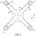
- the elongated arms 110, 111, 112, 113 are both flexible and resilient when a force is applied to the length of one or more of the elongated arms 110, 111, 112, 113. While the elongated arms 110, 111, 112, 113 may have substantially any cross-section that permits this flexible and resilient movement, in at least one embodiment, the elongated arms 110, 111, 112, 113 have a substantially round cross-section with an inwardly directed projection 122 (see FIG. 4 ).
- the flexible skeletal element 102 further includes a plurality of cross-members 124 extending between the elongated arms 110, 111, 112, 113.
- a plurality of living hinges 126 are provided disposed between the plurality of cross-members 124 and the elongated arms 110, 111, 112, 113.
- the term "living hinge” refers to a thinned section or an area of reduced cross-section that provides additional flexibility relative to adjacent structures, in this case, the adjacent cross-member 124 and elongated arms 110, 111, 112, 113.
- the living hinges 126 may best been seen in the cross-sectional view of FIG. 7 .
- the cross-members 124 may present any appropriate shape between the elongated arms 110, 111, 112, 113, and may be of the same or different shapes. In order to minimize interference of the cross-members 124 with bending of the elongated arms 110, 111, 112, 113, the cross-members have a substantially planar structure. While one or more the cross-members 124 may have a square or rectangular shape, for example, the cross-members 124 may include cross-member arms 128 present a substantially planar X shape, as illustrated in FIG. 4 . As may be seen in FIG. 7 , for example, the cross-member arms 128 may include thinned outward ends that include the respective living hinges 126.
- the flexibility of the elongated arms 110, 111, 112, 113 in conjunction with the cross-members 124 and the living hinges 126 facilitate the resilient bending or flexing of the flexible skeletal element 102 around obstacles in multiple directions in use. That is, when a force is applied to one or more of the elongated arms 110, 111, 112, 113, force is transmitted to the remaining of the elongated arms 110, 111, 112, 113 through the living hinges 126 and cross-members 124, while the base ends 114 and the distal ends 116 of the elongated arms 110, 111, 112, 113 are maintained in their respective relative positions.
- the flexibility of the flexible skeletal element 102 may be explained with regard to FIGS. 8 and 9 .
- a force F is applied to a single one of the elongated arms 110, 111, 112, 113, or to a pair of the elongated arms 110, 111, 112, 113, the base 108 and distal element 118 maintain the relative positions of the base ends 114 and the distal ends 116 of the elongated arms 110, 111, 112, 113.
- the force F is applied, however, the force is likewise transmitted to the other of the elongated arms 110, 111, 112, 113 by the plurality of cross-members 124.
- the living hinges 126 flex to allow the positions of the plurality of cross-members 124 to change relative to the elongated arms 110, 111, 112, 113 while transmitting the force, ultimately adjusting the relative positions of the elongated arms 110, 111, 112, 113 along their lengths.
- the living hinges 126 disposed between at least one of the cross-members 124 and said elongated arms 110, 111, 112, 113 flex.
- distance between at least a portion of the length of at least two of the elongated arms 110, 111, 112, 113 is reduced.
- FIG. 8 illustrates a force F 1 being applied at a substantially normal angle to a single one 112 of the elongated arms 110, 111, 112, 113
- FIG. 9 illustrates a force F 2 being applied at a substantially normal angle to a pair 112, 113 of the elongated arms 110, 111, 112, 113.
- the living hinges 126 allow the cross-members 124 to angle relative to the elongated arms 110, 111, 112, 113, allowing at least a portion of the length of at least two of the elongated arms 110, 111, 112, 113 to move closer to one another to allow the flexible skeletal element 102 to bend in response to the applied force. It will be appreciated by those of skill in the art that a force F applied to one or more of the elongated arms 110, 111, 112, 113 at an alternate angle will likewise result in a resilient bending or flexing of the device.
- the bending or flexing may include a twisting of the elongated arms 110, 111, 112, 113 relative to one another.
- a force F 3 applied at an alternate angle to one 110 of the elongate arms 110, 111, 112, 113 may result in a twisting of the elongated arms 110, 111, 112, 113.
- the flexible skeletal element 102 provides an omnidirectional dusting tool 100 that is flexible in multiple planes. In this way, the flexible skeletal element 102 may allow a user to readily dust around structures.
- the illustrated flexible skeletal element 202 likewise includes four elongated arms 210, 211, 212, 213 extending between a base 208 and a distal element 218.
- a plurality of cross-members 224 meet the elongated arms 210, 211, 212, 213 at a plurality of living hinges 226.
- the elongated arms 210, 211, 212, 213 extend in a substantially parallel relationship before converging toward the distal element 218.
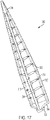
- FIG. 17 illustrates a flexible skeletal element 302 that includes three elongated arms 310, 311, 312, as opposed to four, extending between a base 308 and a distal element 318.
- a plurality of cross-members 324 meet the elongated arms 310, 311, 312 at a plurality of living hinges 326.
- the elongated arms 310, 311, 312 extend in a substantially parallel relationship before converging toward the distal element 318.
- elongated arms 310, 311, 312 may, for example, be substantially straight, converging toward one another from the base 308 to the distal element 318, similar to the embodiment of FIGS. 1-12 .
- the flexible skeletal elements 202, 302 include a protrusion 232, 332 in the form of a button or the like, which can be engaged with a mating opening or the like (not illustrated) in a handle assembly.
- the flexible skeletal element 102, 202, 302 may be fabricated by any appropriate method of any appropriate material that provides desired flexibility and resilience to the flexible skeletal element 102, 202, 302.
- the flexible skeletal element 102, 202, 302 may be formed of a polymeric material such as a neoprene rubber or a thermoplastic polyurethane, and may be formed by injection molding, transfer molding, or 3-D printing.
- the flexible skeletal element 102, 202, 302 may be unitarily formed or molded, or it may be formed with an insert, for example, in the base 108.
- the flexible skeletal element 102 may be fixedly or rotatably coupled to the handle assembly 106 by any appropriate arrangement. While other arrangements may be utilized, in the illustrated embodiment, a distal end 130 of the handle assembly 106 includes a protrusion 132 that is received in a recess 134 in the base 108 of the flexible skeletal element 102. In an alternative embodiment, for example, the handle assembly 106 may include a recess while the base 108 includes a protrusion. In yet another embodiment, clips or fasteners may be provided to couple the flexible skeletal element 102 to the handle assembly 106, and/or the flexible skeletal element 102 and the handle assembly 106 may coupled together by an adhesive.
- the handle assembly 106 may include an elongated portion 136 having a grip element 138.
- the grip element 138 may include a textured surface, for example, or a pliable covering for enhanced user comfort in handling of the dusting tool 100.
- the handle assembly 106 may be any appropriate design, and may be a fixed length or include structure allowing the handle assembly 106 to be effectively shortened.
- the elongated portion 136 of the handle assembly 106 may include a telescoping structure.
- rod section 140 may be telescoped into and out of rod section 142, rod section 142 supporting the grip element 138.
- the elongated portion 136 of the handle assembly 106 may include structure allowing it to be disassembled.
- rod section 144 may be disassembled from rod section 140.
- rod section 140 is provided with a depressible button 146 that is received in an opening 148 in rod section 144. Depression of the button 146 allows the button 146 to disengage from the opening 148 in rod section 144, allowing the rod sections 140, 144 to be separated from one another.
- the handle assembly 106 includes a proximal subassembly 150 including rod sections 140, 142, and a distal subassembly 152 including the rod section 144.
- the handle assembly 106 may further include a selectively pivotable joint 154 pivotably coupling a first adjacent member 156 and a second adjacent member 158 for relative rotation about axis 160, as illustrated in FIGS. 10 - 12 .
- the selectively pivotable joint 154 includes an actuator, here, an actuable lever 162 coupled to the first adjacent member 156, and at least one locking element 164 coupled to the second adjacent member 158.
- the actuable lever 162 is pivotably coupled to the first adjacent member 156 at axis 166.
- a spring element 168 biases an engaging finger 170 of the actuable lever 162 into an engaged position with the at least one locking element 164 in order to maintain the first and second adjacent members 156, 158 in preset relative positions.
- the at least one locking element 164 may include one or more detents 172 disposed to receive the engaging finger 170 of the actuable lever 162.
- the detent 172 of the second adjacent member 158 is in the form of an opening 174 for receiving the engaging finger 170.
- the first adjacent member 160 additionally includes a recess 176. In this way, when the engaging finger 170 of the actuable lever 162 is biased toward the detent 172, the engaging finger 170 extends through the opening 174 of the second adjacent member 158 and into the recess 176 of the first engaging member 156 when the first and second adjacent members 156, 158 are in the extended position.
- the second adjacent member 158 may be pivoted down toward the first adjacent member 156, the engaging finger riding along an outside surface 178 of the second adjacent member 158 to pivot the second adjacent member 158 to the position shown in phantom in FIG. 12 .
- At least one of the base 108 of the flexible skeletal element 102 and the handle assembly 106 further includes a plurality of outwardly extending projections 180.
- the projections 180 are adapted to engage the cloth dusting element 104.
- the projections 180 may engage mating openings or recesses in the cloth dusting element 104, while in some embodiments, the projections may present friction elements for inhibiting movement of the cloth dusting element 104. It will be appreciated that, while this particular embodiment includes a plurality of outwardly extending projections 180, other embodiments may include a greater or lesser number.
- the alternative embodiment of a dusting tool 200 including handle assembly 206 illustrated in FIGS. 13-15 includes a single such outwardly extending projection 280 extending from the handle assembly 206, as opposed to the flexible skeletal element.
- the handle assembly 206 of FIGS. 13-15 may include an elongated portion 236 having a grip element 238, which may include a textured surface.
- the handle assembly 206 may further include a recess 235 to allow the dusting tool 200 to conveniently be hung on a hook or the like (not illustrated), or to receive a looped structure (not illustrated) to allow the looped structure to hang the dusting tool 200 on a hook.
- the handle assembly 206 includes a telescoping structure, which allows the handle assembly 206 to be effectively shortened from the extended position illustrated in FIG. 13 to the shortened positon illustrated in FIG. 13 for sale or storage.
- rod section 241 may be telescoped into and out of rod section 240, which may be telescoped into and out of rod section 242, rod section 242 supporting the grip element 238.
- inserts 237, 239 are disposed within and coupled to the proximal ends of rod sections 241, 240, respectively.
- the inserts 237, 239 include depressible buttons 246, 247, respectively, which are biased to outward positions through openings 248, 249 of the proximal ends of rod sections 241, 240 by spring elements 251, 253, respectively.
- the depressible buttons 246, 247 further are movably received through openings 255, 257 in the distal ends of rod sections 240, 242, respectively, when the elongated portion 236 of the handle assembly 206 is assembled and disposed in the extended position.
- the button 246 may depress the button 246 to allow rod sections 241, 240 to telescopingly slide relative to one another, and depress button 247 to allow rod sections 240, 242 to telescopingly slide relative to one another.
- the elongated portion 236 may be shortened to approximately one-third of its length, as shown in FIG. 13 .
- rod section 244 is coupled with rod section 241.
- rod section 241 may include a depressible button 259 that is received in an opening 261 in rod section 244. Depression of the button 259 allows the button 259 to disengage from the opening 261 in rod section 244, allowing the rod sections 241, 244 to be separated from one another.
- the handle assembly 206 includes a proximal subassembly 250 including rod sections 241, 240, 242, and a distal subassembly 252 including the rod section 244.
- the proximal and distal subassemblies 250, 252 may be maintained in a coupled fashion, conveniently folded to the retracted position illustrated in FIGS. 13 and 14 . That is, the handle assembly 206 may further include a selectively pivotable joint 254 pivotably coupling a first adjacent member 256 and a second adjacent member 258 for relative rotation about axis 260, as illustrated in FIGS. 13-14 . In this embodiment, the first adjacent member 256 is coincident with the rod section 244.
- the second adjacent member 258 includes a protrusion 262 that is disposed along axis 260 within a first recess or opening 264 in the first adjacent member 256, likewise disposed along the axis 260 to pivotably couple the first and second adjacent members 256, 258 (see FIG. 14 ).
- the selectively pivotable joint 254 further includes a locking element 266 that is disposed within a recess 268 of the second adjacent member 258, and biased outward along axis 260 by a spring element 270 seated between the locking element 266 and a recess 272 within protrusion 262.
- the locking element 266 includes an actuator in the form of a depressible button 274 that is disposed through a second opening 276 in the first adjacent member 256, likewise disposed along the axis 260.
- the depressible button 274 and the protrusion 262 of the locking element 266 of the second adjacent member 258 are disposed along the axis 260 extending through or into the first and second openings 264, 276 of the first adjacent member 256 to pivotably couple the first and second adjacent members 256, 258.
- the locking element 266 is in the form of a gear-like structure that includes first and second sets of protrusions or teeth 280, 282.
- a plurality of first recesses or grooves 284 are provided within the recess 268.
- the engagement between the teeth first set of teeth 280 and the plurality of first recesses or grooves 284 of the second adjacent member 258 allows the locking element 266 to slide in an outward direction along the axis 260 as a result of the outward bias due to the spring element 270, or in an inward direction against the bias of the spring element 270 by depression of the depressible button 274.
- the first adjacent member 256 is provided with a second set of recesses or grooves 286.
- the second set of recesses or grooves 286 are disposed about the second opening 276 of the first adjacent member 256.
- the spring element 270 biases the locking element 266 outward within the recess 268 of the second adjacent member 258, the second set of protrusions or teeth 282 are received within the second set of recesses or grooves 286 of the first adjacent member 256. This engagement locks the first and second adjacent members 256, 258 in a given position.
- the locking element 266 slides along the axis 260 as the first set of protrusions or teeth 280 slide along the plurality of first recesses or grooves 284 to disengage the second set of protrusions or teeth 282 from the second set of recesses or grooves 286, allowing the first and second adjacent members 256, 258 to again pivot relative to one another.
Landscapes
- Surgical Instruments (AREA)
- Cleaning Implements For Floors, Carpets, Furniture, Walls, And The Like (AREA)
- Prostheses (AREA)
- Stored Programmes (AREA)
- Eye Examination Apparatus (AREA)
Abstract
Description
- This patent disclosure relates generally to cleaning implements and, more particularly to dusting tools.
- Various tools and have been proposed for facilitating dusting. Some dusting tools include rigid or semi-rigid bars upon which is mounted a cleaning cloth having a plurality of fiber sections. The dusting tools may be attached to a relatively short handle unit for dusting readily accessible surfaces, or a rod or pole to allow the dusting tool to reach elevated surfaces. In use, the dusting tool is moved across the surfaces to be cleaned, and the dust particles are trapped in the fiber sections.
- Many of these devices, however, have limitations regarding effectiveness or ease of use. For example, the bars of this type of dusting tool generally have a rigid design, which makes it difficult or more time consuming to clean curved surfaces. This challenge may be aggravated when a lengthening rod or pole is utilized inasmuch as a rigid section of the dusting tool may be unable to conform to remote curved surfaces. Additionally, the edge areas and corners of elevated surfaces may only be reached with difficulty.
-
U.S. Patent 8,136,196 to Dingert discloses a flexible dusting tool. The device includes two bars connected by film hinges to spacers that extend between the bars. A normal force exerted on one or other of the flat exterior surface of the bars causes the bars to arc, allowing the dusting tool to bend around objects in a plane perpendicular to the bars and film hinges. - The disclosure describes, in one aspect, a dusting tool having a flexible skeletal element including a base, from which four elongated arms extend. The elongated arms have a base end and a distal end. The base ends extend from the base and being spaced apart from one another at the base. The arms being flexible and resilient. A plurality of cross-members extend between the elongated arms, a plurality of living hinges being disposed between the plurality of cross-members and the elongated arms. A force applied to at least one of the elongated arms is transmitted to the other of the elongated arm by the plurality of cross-members and the plurality of living hinges.
- The disclosure describes, in another aspect, dusting tool having a unitarily molded flexible skeletal element and a handle assembly. The flexible skeletal element includes a base, from which four elongated arms extend. The base of the flexible skeletal element is coupled to the handle assembly. The elongated arms have a base end and a distal end. The base ends extend from the base and being spaced apart from one another at the base. The arms being flexible and resilient. A plurality of cross-members extend between the elongated arms, a plurality of living hinges being disposed between the plurality of cross-members and the elongated arms. A force applied to at least one of the elongated arms is transmitted to the other of the elongated arm by the plurality of cross-members and the plurality of living hinges.
-
-
Figure 1 is an isometric view of a dusting tool according to aspects of this disclosure. -
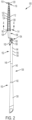
FIG. 2 is a side elevational view of the dusting tool ofFIG. 1 . -
FIG. 3 is a side elevational view of the dusting tool ofFIGS 1 and2 showing a cloth dusting element being applied to the tool. -
FIG. 4 is an enlarged cross-sectional view of a flexible skeletal element of the dusting tool ofFIGS. 1-3 taken along line 4 - 4 inFIG. 2 . -
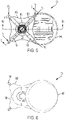
FIG. 5 is an enlarged top plan view of the dusting tool ofFIGS. 1-4 . -
FIG. 6 is an enlarged bottom view of the dusting tool ofFIGS. 1-5 . -
FIG. 7 is an enlarged fragmentary cross-sectional view of the dusting tool ofFIGS. 1-6 taken along line 7 - 7 inFIG. 5 . -
FIG. 8 is an enlarged fragmentary view of a distal end of the dusting tool ofFIGS. 1-7 showing the application of a force. -
FIG. 9 is an enlarged fragmentary view of a distal end of the dusting tool ofFIGS. 1-8 showing the application of a force. -
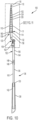
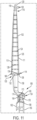
FIG. 10 is a cross-sectional view of the dusting tool ofFIGS. 1-9 taken along line 10 -10 inFIG. 5 . -
FIG. 11 is an enlarged fragmentary view of the dusting tool as illustrated inFIG. 10 . -
FIG. 12 is a side elevational view of the dusting tool ofFIGS. 1-11 showing an alternative position in phantom. -
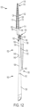
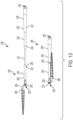
FIG. 13 is a side elevational view of an alternative embodiment of a dusting tool according to teaching of this disclosure in stored and extended positions. -
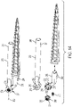
FIG. 14 shows enlarged fragmentary isometric views of the dusting tool as illustrate inFIG. 13 in assembled and exploded positions. -
FIG. 15 shows isometric views of the handle assembly as illustrated inFIG. 13 in assembled and exploded positions. -
FIG. 16 is an isometric view of an alternative embodiment of a flexible skeletal element. -
FIG. 17 is an isometric view of an alternative embodiment of a flexible skeletal element. - This disclosure relates to a
dusting tool 100 that may be particularly useful in dusting around objects. Thedusting tool 100 includes a flexibleskeletal element 102 to which acloth dusting element 104 may be coupled for use in collecting dust (see, e.g.,FIG. 3 ). Ahandle assembly 106 may be coupled to theskeletal element 102 in order to facilitate maneuvering of theskeletal element 102. - The flexible
skeletal element 102 includes abase 108 from which at least three elongated arms extend, the illustrated embodiment including fourelongated arms elongated arms base end 114 and adistal end 116. The base ends 114 of theelongated arms base 108 in a spaced relationship. While theelongated arms base 108 in substantially any configuration, in the illustrated embodiment, theelongated arms base 108 itself is not necessarily in the shape of a square. - The
elongated arms distal ends 116. While theelongated arms elongated arms skeletal element 102 may further include adistal element 118 to which the distal ends 116 of theelongated arms distal element 118 coupling theelongated arms distal ends 116. In the illustrated embodiment, thedistal element 118 has a cone shape, although thedistal element 118 may be of any appropriate shape. In order to assist in maintaining acloth dusting element 104 in position on the flexibleskeletal element 102, thedistal element 118 may include a plurality ofribs 120. - The
elongated arms elongated arms elongated arms elongated arms FIG. 4 ). - The flexible
skeletal element 102 further includes a plurality ofcross-members 124 extending between theelongated arms skeletal element 102, a plurality ofliving hinges 126 are provided disposed between the plurality ofcross-members 124 and theelongated arms adjacent cross-member 124 andelongated arms FIG. 7 . - The cross-members 124 may present any appropriate shape between the
elongated arms elongated arms cross-member arms 128 present a substantially planar X shape, as illustrated inFIG. 4 . As may be seen inFIG. 7 , for example, thecross-member arms 128 may include thinned outward ends that include the respective living hinges 126. - The flexibility of the
elongated arms skeletal element 102 around obstacles in multiple directions in use. That is, when a force is applied to one or more of theelongated arms elongated arms cross-members 124, while the base ends 114 and the distal ends 116 of theelongated arms - The flexibility of the flexible
skeletal element 102 may be explained with regard toFIGS. 8 and9 . Whether a force F is applied to a single one of theelongated arms elongated arms base 108 anddistal element 118 maintain the relative positions of the base ends 114 and the distal ends 116 of theelongated arms elongated arms cross-members 124. That is, the living hinges 126 flex to allow the positions of the plurality ofcross-members 124 to change relative to theelongated arms elongated arms elongated arms elongated arms elongated arms -
FIG. 8 illustrates a force F1 being applied at a substantially normal angle to asingle one 112 of theelongated arms FIG. 9 illustrates a force F2 being applied at a substantially normal angle to apair elongated arms FIGS. 8 and9 , as a force F is applied to one or more of theelongated arms elongated arms elongated arms skeletal element 102 to bend in response to the applied force. It will be appreciated by those of skill in the art that a force F applied to one or more of theelongated arms elongated arms elongate arms FIG. 5 ) may result in a twisting of theelongated arms skeletal element 102 provides anomnidirectional dusting tool 100 that is flexible in multiple planes. In this way, the flexibleskeletal element 102 may allow a user to readily dust around structures. - Alternative embodiments of the flexible
skeletal element 102 are illustrated, for example, inFIGS. 16 and17 . Turning first toFIGS. 16 , the illustrated flexibleskeletal element 202 likewise includes fourelongated arms distal element 218. A plurality ofcross-members 224 meet theelongated arms elongated arms distal element 218.FIG. 17 illustrates a flexibleskeletal element 302 that includes threeelongated arms distal element 318. A plurality ofcross-members 324 meet theelongated arms FIG. 16 , theelongated arms distal element 318. Those of skill in the art will appreciate, however, thatelongated arms distal element 318, similar to the embodiment ofFIGS. 1-12 . The flexibleskeletal elements protrusion - The flexible
skeletal element skeletal element skeletal element skeletal element base 108. - Returning to
FIGS. 1-12 , the flexibleskeletal element 102 may be fixedly or rotatably coupled to thehandle assembly 106 by any appropriate arrangement. While other arrangements may be utilized, in the illustrated embodiment, adistal end 130 of thehandle assembly 106 includes aprotrusion 132 that is received in arecess 134 in thebase 108 of the flexibleskeletal element 102. In an alternative embodiment, for example, thehandle assembly 106 may include a recess while thebase 108 includes a protrusion. In yet another embodiment, clips or fasteners may be provided to couple the flexibleskeletal element 102 to thehandle assembly 106, and/or the flexibleskeletal element 102 and thehandle assembly 106 may coupled together by an adhesive. - The
handle assembly 106 may include anelongated portion 136 having agrip element 138. Thegrip element 138 may include a textured surface, for example, or a pliable covering for enhanced user comfort in handling of the dustingtool 100. - While the
handle assembly 106 may be any appropriate design, and may be a fixed length or include structure allowing thehandle assembly 106 to be effectively shortened. For example, theelongated portion 136 of thehandle assembly 106 may include a telescoping structure. As will be understood by those of skill in the art in viewingFIG. 10 ,rod section 140 may be telescoped into and out ofrod section 142,rod section 142 supporting thegrip element 138. - By way of further example, the
elongated portion 136 of thehandle assembly 106 may include structure allowing it to be disassembled. As likewise illustrated inFIG. 10 ,rod section 144 may be disassembled fromrod section 140. While any appropriate arrangement may be provided to allow disassembly, in the illustrated embodiment,rod section 140 is provided with adepressible button 146 that is received in anopening 148 inrod section 144. Depression of thebutton 146 allows thebutton 146 to disengage from theopening 148 inrod section 144, allowing therod sections handle assembly 106 includes aproximal subassembly 150 includingrod sections distal subassembly 152 including therod section 144. - By way of still further example, the
handle assembly 106 may further include a selectively pivotable joint 154 pivotably coupling a firstadjacent member 156 and a secondadjacent member 158 for relative rotation aboutaxis 160, as illustrated inFIGS. 10 - 12 . While any appropriate mechanism to actuate and maintain the relative positions of the first and secondadjacent members actuable lever 162 coupled to the firstadjacent member 156, and at least onelocking element 164 coupled to the secondadjacent member 158. Theactuable lever 162 is pivotably coupled to the firstadjacent member 156 ataxis 166. As may be seen inFIG. 11 , aspring element 168 biases anengaging finger 170 of theactuable lever 162 into an engaged position with the at least onelocking element 164 in order to maintain the first and secondadjacent members - The at least one
locking element 164 may include one or more detents 172 disposed to receive theengaging finger 170 of theactuable lever 162. In the illustrated embodiment, the detent 172 of the secondadjacent member 158 is in the form of anopening 174 for receiving theengaging finger 170. In order to further secure the relative positions of the first and secondadjacent members adjacent member 160 additionally includes arecess 176. In this way, when theengaging finger 170 of theactuable lever 162 is biased toward the detent 172, the engagingfinger 170 extends through theopening 174 of the secondadjacent member 158 and into therecess 176 of the first engagingmember 156 when the first and secondadjacent members actuable lever 162 is moved against the bias ofspring element 168, the secondadjacent member 158 may be pivoted down toward the firstadjacent member 156, the engaging finger riding along anoutside surface 178 of the secondadjacent member 158 to pivot the secondadjacent member 158 to the position shown in phantom inFIG. 12 . - In at least one embodiment, in order to assist in maintaining the
cloth dusting element 104 in position on the dustingtool 100, at least one of thebase 108 of the flexibleskeletal element 102 and thehandle assembly 106 further includes a plurality of outwardly extendingprojections 180. Theprojections 180 are adapted to engage thecloth dusting element 104. In some embodiments, theprojections 180 may engage mating openings or recesses in thecloth dusting element 104, while in some embodiments, the projections may present friction elements for inhibiting movement of thecloth dusting element 104. It will be appreciated that, while this particular embodiment includes a plurality of outwardly extendingprojections 180, other embodiments may include a greater or lesser number. - For example, the alternative embodiment of a dusting tool 200 including
handle assembly 206 illustrated inFIGS. 13-15 includes a single such outwardly extendingprojection 280 extending from thehandle assembly 206, as opposed to the flexible skeletal element. Thehandle assembly 206 ofFIGS. 13-15 may include anelongated portion 236 having agrip element 238, which may include a textured surface. Thehandle assembly 206 may further include arecess 235 to allow the dusting tool 200 to conveniently be hung on a hook or the like (not illustrated), or to receive a looped structure (not illustrated) to allow the looped structure to hang the dusting tool 200 on a hook. - The
handle assembly 206 includes a telescoping structure, which allows thehandle assembly 206 to be effectively shortened from the extended position illustrated inFIG. 13 to the shortened positon illustrated inFIG. 13 for sale or storage. As will be understood by those of skill in the art in viewingFIGS. 13 and15 , in particular,rod section 241 may be telescoped into and out ofrod section 240, which may be telescoped into and out ofrod section 242,rod section 242 supporting thegrip element 238. - In the illustrated embodiment, inserts 237, 239 are disposed within and coupled to the proximal ends of
rod sections inserts depressible buttons openings rod sections spring elements rod sections depressible buttons openings rod sections elongated portion 236 of thehandle assembly 206 is assembled and disposed in the extended position. In this way, a user may depress thebutton 246 to allowrod sections button 247 to allowrod sections elongated portion 236 may be shortened to approximately one-third of its length, as shown inFIG. 13 . - In the embodiment of
FIGS. 13-15 ,rod section 244 is coupled withrod section 241. As with the first embodiment,rod section 241 may include adepressible button 259 that is received in anopening 261 inrod section 244. Depression of thebutton 259 allows thebutton 259 to disengage from theopening 261 inrod section 244, allowing therod sections handle assembly 206 includes a proximal subassembly 250 includingrod sections rod section 244. - In the embodiment of
FIGS. 13-15 , the proximal and distal subassemblies 250, 252 may be maintained in a coupled fashion, conveniently folded to the retracted position illustrated inFIGS. 13 and14 . That is, thehandle assembly 206 may further include a selectively pivotable joint 254 pivotably coupling a firstadjacent member 256 and a secondadjacent member 258 for relative rotation aboutaxis 260, as illustrated inFIGS. 13-14 . In this embodiment, the firstadjacent member 256 is coincident with therod section 244. - The second
adjacent member 258 includes aprotrusion 262 that is disposed alongaxis 260 within a first recess or opening 264 in the firstadjacent member 256, likewise disposed along theaxis 260 to pivotably couple the first and secondadjacent members 256, 258 (seeFIG. 14 ). The selectively pivotable joint 254 further includes alocking element 266 that is disposed within arecess 268 of the secondadjacent member 258, and biased outward alongaxis 260 by aspring element 270 seated between the lockingelement 266 and arecess 272 withinprotrusion 262. - The locking
element 266 includes an actuator in the form of adepressible button 274 that is disposed through asecond opening 276 in the firstadjacent member 256, likewise disposed along theaxis 260. In this way, thedepressible button 274 and theprotrusion 262 of thelocking element 266 of the secondadjacent member 258 are disposed along theaxis 260 extending through or into the first andsecond openings adjacent member 256 to pivotably couple the first and secondadjacent members - The locking
element 266 is in the form of a gear-like structure that includes first and second sets of protrusions orteeth locking element 266 within therecess 268 of the secondadjacent member 258, a plurality of first recesses orgrooves 284 are provided within therecess 268. In this way, the engagement between the teeth first set ofteeth 280 and the plurality of first recesses orgrooves 284 of the secondadjacent member 258 allows the lockingelement 266 to slide in an outward direction along theaxis 260 as a result of the outward bias due to thespring element 270, or in an inward direction against the bias of thespring element 270 by depression of thedepressible button 274. - In order to secure the first and second
adjacent members adjacent member 256 is provided with a second set of recesses orgrooves 286. The second set of recesses orgrooves 286 are disposed about thesecond opening 276 of the firstadjacent member 256. In this way, as thespring element 270 biases thelocking element 266 outward within therecess 268 of the secondadjacent member 258, the second set of protrusions orteeth 282 are received within the second set of recesses orgrooves 286 of the firstadjacent member 256. This engagement locks the first and secondadjacent members depressible button 274 of thelocking element 266, the lockingelement 266 slides along theaxis 260 as the first set of protrusions orteeth 280 slide along the plurality of first recesses orgrooves 284 to disengage the second set of protrusions orteeth 282 from the second set of recesses orgrooves 286, allowing the first and secondadjacent members - It will be appreciated by those of skill in the art that recesses or grooves are formed between protrusions or teeth. Accordingly, the language utilized in describing the structures relative to the
locking element 266 and the first and secondadjacent members locking element 266 including a plurality of recesses or grooves, and the first and secondadjacent members - It will be appreciated that the foregoing description provides examples of the disclosed system and technique. However, it is contemplated that other implementations of the disclosure may differ in detail from the foregoing examples. All references to the disclosure or examples thereof are intended to reference the particular example being discussed at that point and are not intended to imply any limitation as to the scope of the disclosure more generally. All language of distinction and disparagement with respect to certain features is intended to indicate a lack of preference for those features, but not to exclude such from the scope of the disclosure entirely unless otherwise indicated.
- The use of the terms "a" and "an" and "the" and "at least one" and similar referents in the context of describing the invention (especially in the context of the following claims) are to be construed to cover both the singular and the plural, unless otherwise indicated herein or clearly contradicted by context. The use of the term "at least one" followed by a list of one or more items (for example, "at least one of A and B") is to be construed to mean one item selected from the listed items (A or B) or any combination of two or more of the listed items (A and B), unless otherwise indicated herein or clearly contradicted by context.
- Recitation of ranges of values herein are merely intended to serve as a shorthand method of referring individually to each separate value falling within the range, unless otherwise indicated herein, and each separate value is incorporated into the specification as if it were individually recited herein. All methods described herein can be performed in any suitable order unless otherwise indicated herein or otherwise clearly contradicted by context.
- Accordingly, this disclosure includes all modifications and equivalents of the subject matter recited in the claims appended hereto as permitted by applicable law. Moreover, any combination of the above-described elements in all possible variations thereof is encompassed by the disclosure unless otherwise indicated herein or otherwise clearly contradicted by context.
Claims (24)
- A dusting tool comprising:a flexible skeletal element includinga base;at least three elongated arms, the elongated arms having a base end and a distal end, the base ends extending from the base and being spaced apart from one another at the base, the arms being flexible and resilient;a plurality of cross-members extending between the elongated arms; anda plurality of living hinges disposed between the plurality of cross-members and the elongated arms;wherein a force applied to at least one of the elongated arms is transmitted to the other of the elongated arm by the plurality of cross-members and the plurality of living hinges.
- The dusting tool of claim 1 wherein each of said elongated arms has a length, and wherein the force applied to the at least one of the elongated arms causes at least three of the living hinges disposed between a first of said plurality of cross-members and said elongated arms to flex, and a distance between at least a portion of the length of a first of said elongated arms and a portion of the length of a second of said elongated arms to be reduced.
- The dusting tool of claim 1 wherein the elongated arms converge toward one another from the base ends to the distal ends.
- The dusting tool of claim 1 wherein the distal ends of the elongated arms are coupled together.
- The dusting tool of claim 4 further comprising a distal element, the distal ends of the elongated arms being connected to and coupled together by the distal element.
- The dusting tool of claim 5 wherein the elongated arms extend substantially parallel to one another from the base before converging toward one another and being coupled together by the distal element.
- The dusting tool of claim 5 wherein the distal element has a cone shape and includes a plurality of ribs.
- The dusting tool of claim 1 wherein the plurality of cross-members includes a plurality of cross-member arms.
- The dusting tool of claim 8 wherein the plurality of cross-member arms include thinned distal ends, and the plurality of living hinges includes said thinned distal ends.
- The dusting tool of claim 1 wherein the elongated arms have a cross-section, the cross-section including a projection, the projection being disposed toward adjacent living hinges.
- The dusting tool of claim 1 wherein the flexible skeletal element is omnidirectionally flexible when at least one outside force is applied to at least one of the at least three elongated arms.
- The dusting tool of claim 1 including four elongated arms.
- The dusting tool of claim 1 comprising a handle assembly, the flexible skeletal element being coupled to the handle assembly.
- The dusting tool of claim 13 wherein at least one of the base and the handle assembly further includes at least one outwardly extending projection wherein the projection is adapted to engage a cleaning cloth.
- The dusting tool of claim 13 wherein the handle assembly includes a grip element.
- The dusting tool of claim 13 wherein the flexible skeletal element is rotatably coupled to the handle assembly.
- The dusting tool of claim 13 wherein one of the handle assembly and the base includes a protrusion and the other of the handle assembly and the base includes a recess, the protrusion being received within the recess.
- The dusting tool of claim 13 wherein the handle assembly includes an elongated rod.
- The dusting tool of claim 18 wherein the elongated rod includes at least one of a telescoping section whereby the dusting tool may be lengthened or shortened, and a separable connection whereby the dusting tool may disassembled into at least two subassemblies.
- The dusting tool of claim 13 wherein the handle assembly further includes a selectively pivotable joint.
- The dusting tool of claim 20 wherein the selectively pivotable joint includes an actuator coupled to at least one of a first adjacent member and a second adjacent member, and at least one locking element coupled to at least one of the first adjacent member and the second adjacent member, the actuator being selectively movable to cause engagement of the at least one locking element to retain first adjacent member and the second adjacent member in preset relative positions.
- The dusting tool of claim 1 further comprising a cloth dusting element disposed over and coupled to the flexible skeletal element.
- A dusting tool comprising:a flexible skeletal element includinga base;at least three elongated arms having a length, the elongated arms having a base end and a distal end, the base ends extending from the base and being spaced apart from one another at the base, the arms being flexible and resilient;a plurality of cross-members extending between the elongated arms; anda plurality of living hinges disposed between the plurality of cross-members and the elongated arms;wherein a force applied to at least one of the elongated arms causes at least three of the living hinges disposed between a first of said plurality of cross-members and said elongated arms to bend, and a distance between at least a portion of the length of a first of said elongated arms and a portion of the length of a second of said elongated arms to be reduced.
- A dusting tool comprising:a flexible skeletal element includinga base;four elongated arms, the elongated arms having a base end and a distal end, the base ends extending from the base and being spaced apart from one another at the base, the arms being flexible and resilient;a distal element, the distal ends of the elongated arms being coupled together at the distal element, the elongated arms converge toward one another from the base ends to the distal ends;a plurality of cross-members disposed between the elongated arms, the plurality of cross-members includes a plurality of cross-member arms; anda plurality of living hinges extending between the plurality of cross-members and the elongated arms;wherein the flexible skeletal element is unitarily molded; andwherein the flexible skeletal element is omnidirectionally flexible when at least one outside force is applied to at least one of the four elongated arms;a handle assembly, the base being coupled to the handle assembly.
Applications Claiming Priority (1)
| Application Number | Priority Date | Filing Date | Title |
|---|---|---|---|
| US17/478,700 US11564549B1 (en) | 2021-09-17 | 2021-09-17 | Multidirectional dusting tool |
Publications (2)
| Publication Number | Publication Date |
|---|---|
| EP4151136A1 true EP4151136A1 (en) | 2023-03-22 |
| EP4151136B1 EP4151136B1 (en) | 2025-11-05 |
Family
ID=83228852
Family Applications (1)
| Application Number | Title | Priority Date | Filing Date |
|---|---|---|---|
| EP22194192.5A Active EP4151136B1 (en) | 2021-09-17 | 2022-09-06 | Multidirectional dusting tool |
Country Status (11)
| Country | Link |
|---|---|
| US (1) | US11564549B1 (en) |
| EP (1) | EP4151136B1 (en) |
| CN (1) | CN115813296A (en) |
| AU (1) | AU2022218574B2 (en) |
| CA (1) | CA3171642C (en) |
| CL (1) | CL2022002486A1 (en) |
| DK (1) | DK4151136T3 (en) |
| ES (1) | ES3062262T3 (en) |
| FI (1) | FI4151136T3 (en) |
| MX (1) | MX2022011585A (en) |
| PT (1) | PT4151136T (en) |
Cited By (1)
| Publication number | Priority date | Publication date | Assignee | Title |
|---|---|---|---|---|
| WO2024120965A1 (en) * | 2022-12-07 | 2024-06-13 | Carl Freudenberg Kg | Cleaning article |
Families Citing this family (2)
| Publication number | Priority date | Publication date | Assignee | Title |
|---|---|---|---|---|
| US11744432B1 (en) * | 2019-05-06 | 2023-09-05 | Contec Inc. | Adjustable dusting tool and related method |
| USD1093793S1 (en) * | 2024-10-31 | 2025-09-16 | Lanhu Brand Management (Hangzhou) Co., Ltd | Dusting tool |
Citations (3)
| Publication number | Priority date | Publication date | Assignee | Title |
|---|---|---|---|---|
| US20060288508A1 (en) * | 2004-12-14 | 2006-12-28 | Knopow Jeremy F | Extendable cleaning implement having two support heads |
| EP1982629A1 (en) * | 2007-04-16 | 2008-10-22 | Carl Freudenberg KG | Dust brushing device |
| EP3187088A1 (en) * | 2014-08-08 | 2017-07-05 | Unicharm Corporation | Cleaning sheet and cleaning instrument package |
Family Cites Families (8)
| Publication number | Priority date | Publication date | Assignee | Title |
|---|---|---|---|---|
| PL339772A1 (en) * | 1997-09-26 | 2001-01-02 | Smithkline Beecham Gmbh & Co | Tooth brush |
| US7356869B2 (en) * | 2005-04-15 | 2008-04-15 | S.C. Johnson & Son, Inc. | Flexible cleaning tool with replaceable non-woven pad |
| US20070180640A1 (en) * | 2005-01-28 | 2007-08-09 | S. C. Johnson & Son, Inc. | Flexible Cleaning Tool With Replaceable Non-woven Pad and Cleaning Fluid Reservoir |
| US7784141B2 (en) * | 2005-01-28 | 2010-08-31 | S. C. Johnson & Son, Inc. | Flexible cleaning tool with replaceable non-woven pad and cleaning fluid reservoir |
| DE102005008199A1 (en) * | 2005-02-22 | 2006-08-31 | Glaxosmithkline Consumer Healthcare Gmbh & Co. Kg | Toothbrush includes moulding element with flexible cheeks forming wedge set inside brush to adapt to tooth surface when cleaning pressure is applied |
| JP5296682B2 (en) * | 2006-08-11 | 2013-09-25 | グラクソスミスクライン・コンシューマー・ヘルスケア・ゲゼルシャフト・ミット・ベシュレンクテル・ハフツング・ウント・コムパニー・コマンディットゲゼルシャフト | toothbrush |
| JP5235493B2 (en) * | 2008-05-15 | 2013-07-10 | ユニ・チャーム株式会社 | Cleaning tool, cleaning body holder |
| AU2015411340B2 (en) * | 2015-10-09 | 2019-01-17 | Colgate-Palmolive Company | Oral care implement |
-
2021
- 2021-09-17 US US17/478,700 patent/US11564549B1/en active Active
-
2022
- 2022-08-18 AU AU2022218574A patent/AU2022218574B2/en active Active
- 2022-08-29 CA CA3171642A patent/CA3171642C/en active Active
- 2022-09-06 PT PT221941925T patent/PT4151136T/en unknown
- 2022-09-06 ES ES22194192T patent/ES3062262T3/en active Active
- 2022-09-06 FI FIEP22194192.5T patent/FI4151136T3/en active
- 2022-09-06 EP EP22194192.5A patent/EP4151136B1/en active Active
- 2022-09-06 DK DK22194192.5T patent/DK4151136T3/en active
- 2022-09-12 CL CL2022002486A patent/CL2022002486A1/en unknown
- 2022-09-15 MX MX2022011585A patent/MX2022011585A/en unknown
- 2022-09-16 CN CN202211126757.6A patent/CN115813296A/en active Pending
Patent Citations (4)
| Publication number | Priority date | Publication date | Assignee | Title |
|---|---|---|---|---|
| US20060288508A1 (en) * | 2004-12-14 | 2006-12-28 | Knopow Jeremy F | Extendable cleaning implement having two support heads |
| EP1982629A1 (en) * | 2007-04-16 | 2008-10-22 | Carl Freudenberg KG | Dust brushing device |
| US8136196B2 (en) | 2007-04-16 | 2012-03-20 | Carl Freudenberg Kg | Dusting tool |
| EP3187088A1 (en) * | 2014-08-08 | 2017-07-05 | Unicharm Corporation | Cleaning sheet and cleaning instrument package |
Cited By (1)
| Publication number | Priority date | Publication date | Assignee | Title |
|---|---|---|---|---|
| WO2024120965A1 (en) * | 2022-12-07 | 2024-06-13 | Carl Freudenberg Kg | Cleaning article |
Also Published As
| Publication number | Publication date |
|---|---|
| AU2022218574B2 (en) | 2023-11-02 |
| MX2022011585A (en) | 2023-10-17 |
| CL2022002486A1 (en) | 2023-03-03 |
| CN115813296A (en) | 2023-03-21 |
| CA3171642A1 (en) | 2023-03-17 |
| ES3062262T3 (en) | 2026-04-09 |
| US11564549B1 (en) | 2023-01-31 |
| DK4151136T3 (en) | 2026-02-02 |
| EP4151136B1 (en) | 2025-11-05 |
| PT4151136T (en) | 2025-12-18 |
| AU2022218574A1 (en) | 2023-04-06 |
| CA3171642C (en) | 2025-10-14 |
| FI4151136T3 (en) | 2026-02-02 |
Similar Documents
| Publication | Publication Date | Title |
|---|---|---|
| EP4151136B1 (en) | Multidirectional dusting tool | |
| US9107490B2 (en) | Multi-axis articulated implement | |
| CA2931655C (en) | Multi-purpose cleaning implement | |
| US7281288B1 (en) | Cleaning apparatus with flexible connection between head and handle | |
| US12239216B2 (en) | Cleaning devices having selectively flexible or rigid handles | |
| US7055204B2 (en) | Cleaning device | |
| US7640617B2 (en) | Cleaning device including a pivot joint | |
| US8640296B2 (en) | Adjustable cleaning head for a cleaning tool | |
| US8136195B2 (en) | Handle for a floor cleaning implement | |
| US20030009839A1 (en) | Cleaning implement and joint therefor | |
| EP1537817A1 (en) | Bendable extension pipe for a vacuum cleaner | |
| US8984701B2 (en) | Flexible handle for cleaning tools | |
| EP3354181B1 (en) | Cleaning devices for cleaning of difficult to reach locations | |
| GB2192784A (en) | A twin-headed toothbrush | |
| WO2015073829A1 (en) | Extendable tool attachment stick | |
| WO2015103488A1 (en) | Oral hygiene tool | |
| CN108135347A (en) | Oral care implement | |
| EP2869746B1 (en) | Cleaning device having a variable size and shape head | |
| EP4424474B1 (en) | Gripper device | |
| CN216796837U (en) | Broom with telescopic handle | |
| US20190125159A1 (en) | Duster | |
| CA2941291A1 (en) | Cleaning tool handle with sliding locking flexible extension | |
| EP2332444B1 (en) | Brush having a resiliently articulated handgrip |
Legal Events
| Date | Code | Title | Description |
|---|---|---|---|
| PUAI | Public reference made under article 153(3) epc to a published international application that has entered the european phase |
Free format text: ORIGINAL CODE: 0009012 |
|
| STAA | Information on the status of an ep patent application or granted ep patent |
Free format text: STATUS: THE APPLICATION HAS BEEN PUBLISHED |
|
| STAA | Information on the status of an ep patent application or granted ep patent |
Free format text: STATUS: REQUEST FOR EXAMINATION WAS MADE |
|
| AK | Designated contracting states |
Kind code of ref document: A1 Designated state(s): AL AT BE BG CH CY CZ DE DK EE ES FI FR GB GR HR HU IE IS IT LI LT LU LV MC MK MT NL NO PL PT RO RS SE SI SK SM TR |
|
| 17P | Request for examination filed |
Effective date: 20230302 |
|
| RBV | Designated contracting states (corrected) |
Designated state(s): AL AT BE BG CH CY CZ DE DK EE ES FI FR GB GR HR HU IE IS IT LI LT LU LV MC MK MT NL NO PL PT RO RS SE SI SK SM TR |
|
| STAA | Information on the status of an ep patent application or granted ep patent |
Free format text: STATUS: EXAMINATION IS IN PROGRESS |
|
| 17Q | First examination report despatched |
Effective date: 20230728 |
|
| GRAP | Despatch of communication of intention to grant a patent |
Free format text: ORIGINAL CODE: EPIDOSNIGR1 |
|
| STAA | Information on the status of an ep patent application or granted ep patent |
Free format text: STATUS: GRANT OF PATENT IS INTENDED |
|
| INTG | Intention to grant announced |
Effective date: 20250203 |
|
| GRAJ | Information related to disapproval of communication of intention to grant by the applicant or resumption of examination proceedings by the epo deleted |
Free format text: ORIGINAL CODE: EPIDOSDIGR1 |
|
| STAA | Information on the status of an ep patent application or granted ep patent |
Free format text: STATUS: EXAMINATION IS IN PROGRESS |
|
| INTC | Intention to grant announced (deleted) | ||
| GRAP | Despatch of communication of intention to grant a patent |
Free format text: ORIGINAL CODE: EPIDOSNIGR1 |
|
| STAA | Information on the status of an ep patent application or granted ep patent |
Free format text: STATUS: GRANT OF PATENT IS INTENDED |
|
| INTG | Intention to grant announced |
Effective date: 20250605 |
|
| GRAS | Grant fee paid |
Free format text: ORIGINAL CODE: EPIDOSNIGR3 |
|
| GRAA | (expected) grant |
Free format text: ORIGINAL CODE: 0009210 |
|
| STAA | Information on the status of an ep patent application or granted ep patent |
Free format text: STATUS: THE PATENT HAS BEEN GRANTED |
|
| AK | Designated contracting states |
Kind code of ref document: B1 Designated state(s): AL AT BE BG CH CY CZ DE DK EE ES FI FR GB GR HR HU IE IS IT LI LT LU LV MC MK MT NL NO PL PT RO RS SE SI SK SM TR |
|
| REG | Reference to a national code |
Ref country code: CH Ref legal event code: F10 Free format text: ST27 STATUS EVENT CODE: U-0-0-F10-F00 (AS PROVIDED BY THE NATIONAL OFFICE) Effective date: 20251105 Ref country code: GB Ref legal event code: FG4D |
|
| REG | Reference to a national code |
Ref country code: DE Ref legal event code: R096 Ref document number: 602022024307 Country of ref document: DE |
|
| REG | Reference to a national code |
Ref country code: IE Ref legal event code: FG4D |
|
| REG | Reference to a national code |
Ref country code: PT Ref legal event code: SC4A Ref document number: 4151136 Country of ref document: PT Date of ref document: 20251218 Kind code of ref document: T Free format text: AVAILABILITY OF NATIONAL TRANSLATION Effective date: 20251211 |
|
| REG | Reference to a national code |
Ref country code: FI Ref legal event code: FGE Ref country code: DK Ref legal event code: T3 Effective date: 20260126 |
|
| REG | Reference to a national code |
Ref country code: NL Ref legal event code: MP Effective date: 20251105 |
|
| P01 | Opt-out of the competence of the unified patent court (upc) registered |
Free format text: CASE NUMBER: UPC_APP_0008459_4151136/2026 Effective date: 20260303 |
|
| REG | Reference to a national code |
Ref country code: ES Ref legal event code: FG2A Ref document number: 3062262 Country of ref document: ES Kind code of ref document: T3 Effective date: 20260409 |
|
| REG | Reference to a national code |
Ref country code: LT Ref legal event code: MG9D |
|
| PG25 | Lapsed in a contracting state [announced via postgrant information from national office to epo] |
Ref country code: AT Free format text: LAPSE BECAUSE OF FAILURE TO SUBMIT A TRANSLATION OF THE DESCRIPTION OR TO PAY THE FEE WITHIN THE PRESCRIBED TIME-LIMIT Effective date: 20251105 Ref country code: HR Free format text: LAPSE BECAUSE OF FAILURE TO SUBMIT A TRANSLATION OF THE DESCRIPTION OR TO PAY THE FEE WITHIN THE PRESCRIBED TIME-LIMIT Effective date: 20251105 |
|
| REG | Reference to a national code |
Ref country code: AT Ref legal event code: MK05 Ref document number: 1853374 Country of ref document: AT Kind code of ref document: T Effective date: 20251105 |
|
| PG25 | Lapsed in a contracting state [announced via postgrant information from national office to epo] |
Ref country code: NL Free format text: LAPSE BECAUSE OF FAILURE TO SUBMIT A TRANSLATION OF THE DESCRIPTION OR TO PAY THE FEE WITHIN THE PRESCRIBED TIME-LIMIT Effective date: 20251105 |
|
| PG25 | Lapsed in a contracting state [announced via postgrant information from national office to epo] |
Ref country code: RS Free format text: LAPSE BECAUSE OF FAILURE TO SUBMIT A TRANSLATION OF THE DESCRIPTION OR TO PAY THE FEE WITHIN THE PRESCRIBED TIME-LIMIT Effective date: 20260205 |
|
| PG25 | Lapsed in a contracting state [announced via postgrant information from national office to epo] |
Ref country code: IS Free format text: LAPSE BECAUSE OF FAILURE TO SUBMIT A TRANSLATION OF THE DESCRIPTION OR TO PAY THE FEE WITHIN THE PRESCRIBED TIME-LIMIT Effective date: 20260305 |
|
| PG25 | Lapsed in a contracting state [announced via postgrant information from national office to epo] |
Ref country code: LV Free format text: LAPSE BECAUSE OF FAILURE TO SUBMIT A TRANSLATION OF THE DESCRIPTION OR TO PAY THE FEE WITHIN THE PRESCRIBED TIME-LIMIT Effective date: 20251105 |
|
| PG25 | Lapsed in a contracting state [announced via postgrant information from national office to epo] |
Ref country code: BG Free format text: LAPSE BECAUSE OF FAILURE TO SUBMIT A TRANSLATION OF THE DESCRIPTION OR TO PAY THE FEE WITHIN THE PRESCRIBED TIME-LIMIT Effective date: 20251105 |