EP4151103A1 - Aerosol generating device, and susceptor - Google Patents
Aerosol generating device, and susceptor Download PDFInfo
- Publication number
- EP4151103A1 EP4151103A1 EP21803080.7A EP21803080A EP4151103A1 EP 4151103 A1 EP4151103 A1 EP 4151103A1 EP 21803080 A EP21803080 A EP 21803080A EP 4151103 A1 EP4151103 A1 EP 4151103A1
- Authority
- EP
- European Patent Office
- Prior art keywords
- susceptor
- generation device
- aerosol generation
- cavity
- size
- Prior art date
- Legal status (The legal status is an assumption and is not a legal conclusion. Google has not performed a legal analysis and makes no representation as to the accuracy of the status listed.)
- Granted
Links
Images




Classifications
-
- H—ELECTRICITY
- H05—ELECTRIC TECHNIQUES NOT OTHERWISE PROVIDED FOR
- H05B—ELECTRIC HEATING; ELECTRIC LIGHT SOURCES NOT OTHERWISE PROVIDED FOR; CIRCUIT ARRANGEMENTS FOR ELECTRIC LIGHT SOURCES, IN GENERAL
- H05B6/00—Heating by electric, magnetic or electromagnetic fields
- H05B6/02—Induction heating
- H05B6/10—Induction heating apparatus, other than furnaces, for specific applications
- H05B6/105—Induction heating apparatus, other than furnaces, for specific applications using a susceptor
- H05B6/108—Induction heating apparatus, other than furnaces, for specific applications using a susceptor for heating a fluid
-
- A—HUMAN NECESSITIES
- A24—TOBACCO; CIGARS; CIGARETTES; SIMULATED SMOKING DEVICES; SMOKERS' REQUISITES
- A24F—SMOKERS' REQUISITES; MATCH BOXES; SIMULATED SMOKING DEVICES
- A24F40/00—Electrically operated smoking devices; Component parts thereof; Manufacture thereof; Maintenance or testing thereof; Charging means specially adapted therefor
- A24F40/40—Constructional details, e.g. connection of cartridges and battery parts
- A24F40/46—Shape or structure of electric heating means
- A24F40/465—Shape or structure of electric heating means specially adapted for induction heating
-
- A—HUMAN NECESSITIES
- A24—TOBACCO; CIGARS; CIGARETTES; SIMULATED SMOKING DEVICES; SMOKERS' REQUISITES
- A24F—SMOKERS' REQUISITES; MATCH BOXES; SIMULATED SMOKING DEVICES
- A24F40/00—Electrically operated smoking devices; Component parts thereof; Manufacture thereof; Maintenance or testing thereof; Charging means specially adapted therefor
- A24F40/20—Devices using solid inhalable precursors
-
- A—HUMAN NECESSITIES
- A24—TOBACCO; CIGARS; CIGARETTES; SIMULATED SMOKING DEVICES; SMOKERS' REQUISITES
- A24F—SMOKERS' REQUISITES; MATCH BOXES; SIMULATED SMOKING DEVICES
- A24F40/00—Electrically operated smoking devices; Component parts thereof; Manufacture thereof; Maintenance or testing thereof; Charging means specially adapted therefor
- A24F40/50—Control or monitoring
- A24F40/51—Arrangement of sensors
-
- A—HUMAN NECESSITIES
- A24—TOBACCO; CIGARS; CIGARETTES; SIMULATED SMOKING DEVICES; SMOKERS' REQUISITES
- A24F—SMOKERS' REQUISITES; MATCH BOXES; SIMULATED SMOKING DEVICES
- A24F40/00—Electrically operated smoking devices; Component parts thereof; Manufacture thereof; Maintenance or testing thereof; Charging means specially adapted therefor
- A24F40/50—Control or monitoring
- A24F40/53—Monitoring, e.g. fault detection
-
- H—ELECTRICITY
- H05—ELECTRIC TECHNIQUES NOT OTHERWISE PROVIDED FOR
- H05B—ELECTRIC HEATING; ELECTRIC LIGHT SOURCES NOT OTHERWISE PROVIDED FOR; CIRCUIT ARRANGEMENTS FOR ELECTRIC LIGHT SOURCES, IN GENERAL
- H05B6/00—Heating by electric, magnetic or electromagnetic fields
- H05B6/02—Induction heating
- H05B6/06—Control, e.g. of temperature, of power
-
- H—ELECTRICITY
- H05—ELECTRIC TECHNIQUES NOT OTHERWISE PROVIDED FOR
- H05B—ELECTRIC HEATING; ELECTRIC LIGHT SOURCES NOT OTHERWISE PROVIDED FOR; CIRCUIT ARRANGEMENTS FOR ELECTRIC LIGHT SOURCES, IN GENERAL
- H05B6/00—Heating by electric, magnetic or electromagnetic fields
- H05B6/02—Induction heating
- H05B6/10—Induction heating apparatus, other than furnaces, for specific applications
- H05B6/105—Induction heating apparatus, other than furnaces, for specific applications using a susceptor
-
- H—ELECTRICITY
- H05—ELECTRIC TECHNIQUES NOT OTHERWISE PROVIDED FOR
- H05B—ELECTRIC HEATING; ELECTRIC LIGHT SOURCES NOT OTHERWISE PROVIDED FOR; CIRCUIT ARRANGEMENTS FOR ELECTRIC LIGHT SOURCES, IN GENERAL
- H05B6/00—Heating by electric, magnetic or electromagnetic fields
- H05B6/02—Induction heating
- H05B6/36—Coil arrangements
Definitions
- Embodiments of this application relate to the field of heat-not-burn cigarette device technologies, and in particular, to an aerosol generation device and a susceptor.
- Tobacco products (such as cigarettes, cigars, and the like) burn tobacco during use to produce tobacco smoke. Attempts are made to replace these tobacco-burning products by making products that release compounds without burning.
- the materials may be tobacco or other non-tobacco products. These non-tobacco products may include or not include nicotine.
- the related art provides a heating device of an electromagnetic induction heating type. A structure of the heating device is shown in FIG. 1 . When a tobacco product 1 is accommodated in the heating device, a susceptor 2 is penetrated by an alternating magnetic field generated by an induction coil 3 to inductively generate heat, thereby heating the tobacco product 1.
- the heating device During heating, for convenience of monitoring a heating temperature of the tobacco product 1 in real time, the heating device adopts a temperature sensor 4 that is closely attached to the susceptor 2 to sense a real-time operating temperature of the susceptor 2.
- the heating device adjusts parameters of the alternating magnetic field generated by the induction coil 3 based on a sensing result of the temperature sensor 4, so that the susceptor 2 is within an appropriate heating temperature range.
- the temperature sensor 4 is usually made of a thermistor metal material and will generate heat by itself in the alternating magnetic field.
- the temperature sensor 4 made of metal materials and the susceptor 2 each generate an induced current, which affects a sensing signal outputted by the temperature sensor 4, thereby affecting the accuracy of the sensing signal.
- the embodiments of this application provide a susceptor for an aerosol generation device and an aerosol generation device.
- an aerosol generation device configured to heat an inhalable material to generate an aerosol, and including:
- the susceptor includes a first sheet-like object and a second sheet-like object that are opposite to each other in the thickness direction, and the accommodation cavity is formed between the first sheet-like object and the second sheet-like object.
- the temperature sensor further includes a conductive connection portion at least partially located outside the susceptor, to receive the temperature sensed by the temperature sensor through the conductive connection portion during use.
- the conductive connection portion includes a long and thin conductive pin.
- the conductive connection portion includes an electrical contact formed on or integrated into a surface of the susceptor.
- the susceptor further includes a base part configured to hold the first part and the second part; and the electrical contact is formed on or integrated into a surface of the base part.
- the cavity has an opening end that receives the inhalable material in a removable manner; and a protrusion height of at least a part of the second part relative to the first part gradually decreases in a direction close to the opening end.
- the cavity has an opening end that receives the inhalable material in a removable manner;
- the accommodation cavity includes a conical region whose cross-sectional area gradually decreases in a direction close to the opening end; and the temperature sensor is accommodated or encapsulated in the conical region.
- the first part is provided with a vacancy extending in a length direction; and the second part is constructed to be a pin or in a needle shape extending in the length direction, and is held in the vacancy.
- a surface of the second part is a smooth arc surface.
- the first sheet-like object and/or the second sheet-like object is provided with a protruding part protruding outward in the thickness direction, and the protruding part defines the accommodation cavity.
- a susceptor for an aerosol generation device configured to be penetrated by a changing magnetic field and generate heat, to heat an inhalable material, where the susceptor is constructed in a blade shape extending in an axial direction of the cavity, and includes:
- the aerosol generation device and the susceptor of this application encapsulates or accommodates the temperature sensor in the susceptor.
- a sensing part may be basically insulated from the impact of the magnetic field, and on the other hand, the susceptor and the temperature sensor may be integrated to increase the stability of mounting and the accuracy of temperature detecting, and meanwhile, overall replacement and mounting are easier.
- an aerosol generation device provided in an embodiment of this application includes:
- the inductance coil L may include a cylindrical inductor coil wound into a spiral shape, as shown in FIG. 2 .
- the cylindrical inductance coil L wound into the spiral shape may have a radius r ranging from about 5 mm to about 10 mm, and the radius r may be about 7 mm in particular.
- the cylindrical inductance coil L wound into the spiral shape may have a length ranging from about 8 mm to about 14 mm, and the number of turns of the inductance coil L may range from 8 to 15.
- an inner volume may range from about 0.15 cm 3 to about 1.10 cm 3 .
- a frequency of the alternating current supplied by the circuit 20 to the inductance coil L ranges from 80 KHz to 400 KHz, and more specifically, the frequency may range from about 200 KHz to 300 KHz.
- the direct-current voltage supplied by the core 10 ranges from about 2.5 V to about 9.0 V, and the direct current supplied by the core 10 ranges from about 2.5 A to about 20 A.
- the susceptor 30 in FIG. 2 is made of a metal or an alloy material with an appropriate magnetic conductivity, so that when used, the susceptor 30 can inductively generate heat corresponding to the magnetic field to heat the accommodated inhalable material A to generate the aerosol for inhaling.
- the susceptor 30 may be made of grade 420 stainless steel (SS420), and an alloy material (such as J85/J66 permalloy) containing iron and nickel.
- the aerosol generation device further includes a tubular holder 40 configured to arrange the inductance coil L and mount the susceptor 30.
- the tubular holder 40 may be made of a high-temperature resistant non-metal material, for example, PEEK, ceramic, or the like.
- the inductance coil L is arranged on an outer wall of the tubular holder 40 in a spirally wound manner, and at least a part of the tubular holder 40 is internally hollow to form the cavity configured to accommodate the inhalable material A.
- the susceptor 30 includes: a first part 31 constructed in a blade shape extending in an axial direction of the cavity, and a second part 32 constructed to be a pin or in a needle shape extending in the axial direction of the cavity.
- the first part 31 has a vacancy 311 extending in the axial direction, and the second part 32 is held in the vacancy 311.
- the first part 31 and the second part 32 may be simultaneously inserted into the inhalable material A and then heat the inhalable material A.
- the second part 32 is a hollow structure in which an accommodation cavity 321 extending in the axial direction is arranged.
- the accommodation cavity 321 is configured to accommodate and encapsulate a temperature sensor 50.
- the temperature sensor may be encapsulated inside the second part 32 by gluing, and the like, and is closely attached to an inner wall of the second part 32, so as to accurately detect a real-time operating temperature of the susceptor 30.
- the susceptor further includes a base part 33.
- the first part 31, the second part 32, and the base part 33 are fixed as an indivisible integral by soldering, interference fitting, or the like.
- the base part 33 is constructed into a plate perpendicular to the first part 31 and the second part 32, and has a size greater than that of the first part 31 and the second part 32, so as to be mounted and fixed in the tubular holder 40 by abutting, clamping, and the like.
- the base part 33 has a through hole 331 configured for a conductive pin 51 of the temperature sensor 50 to run through and be exposed outside the susceptor 30, so that the conductive pin 51 is electrically connected to the circuit 20 to supply power and receive a sensing signal.
- a size of an outer diameter of the second part 32 is greater than a thickness of a sheet of the first part. Therefore, the second part 32 can protrude from two sides of the first part 31 in a thickness direction, so that the susceptor 30 can have a relatively larger surface area to be in contact with the inhalable material A, thereby increasing the efficiency of heat transfer during heating.
- the base part 33 is made of a material with a low thermal conductivity, for example, zirconia ceramic, and the like.
- the first part 31 and the second part 32 may be fixed by close fitting, and the like.
- an outer surface of a second part 32a is provided with grooves 322a extending in the axial direction.
- a first part 31 may be integrated with the second part 32a by being embedded into the grooves 322a to be clamped.
- a conductive contact 51b which is exposed outside an outer surface of the susceptor 30b is formed on a surface of the base part 33b by digital printing, analogue printing, depositing, or etching, and is configured to be connected to a pin of the temperature sensor by soldering, and the like.
- the circuit 20 may abut against the conductive contact 51b by a contact conductive mechanism such as a commonly used conductive elastic pin, to supply power to the temperature sensor or receive a sensing signal, so as to avoid inconvenience caused to the replacing and detaching of the susceptor 30 by soldering the pin of the temperature sensor to the circuit 20.
- a contact conductive mechanism such as a commonly used conductive elastic pin
- a susceptor 30c is constructed into a blade shape, and has a first end 31c and a second end 32c.
- the first end 31c is opposite to an opening of the cavity configured to accommodate the inhalable material A.
- the first end 31c as a free end, is constructed into a tip shape for being easily inserted into the inhalable material A that is accommodated in the cavity through an opening end.
- the second end 32c as an end portion for mounting and connecting, is configured to provide support through the tubular holder 40, so that the susceptor 30c is stably held and fixedly mounted in the device.
- the construction of the susceptor 30c is formed by a first sheet-like object 310c and a second sheet-like object 320c that are opposite to each other in the thickness direction.
- the first sheet-like object 310c includes a flat and straight first part 311c, a second part 312c formed by the first part 311c protruding outward in the thickness direction, and a third part 313c formed by at least a part of the first part 311c close to the second end 32c extending in a width direction.
- a shape of the second sheet-like object 320c is similar to that of the first sheet-like object 310c.
- the second sheet-like object 320c also has a flat and straight fourth part 321c, a fifth part 322c formed by the fourth part 321c protruding outward in the thickness direction, and a sixth part 323c formed by at least a part of the fourth part 321c close to the second end 32c extending in the width direction.
- an accommodation cavity 330c configured to accommodate and encapsulate a temperature sensor 340c is formed between the two sheet-like objects.
- the accommodation cavity 330c is formed by a first recessed structure 331 formed by the second part 312c of the first sheet-like object 310c, and a second recessed structure 332c formed by the fifth part 322c of the second sheet-like object 320c.
- a sensing part 341c of the temperature sensor 340c is accommodated and encapsulated in the accommodation cavity 330c, and may be encapsulated and fixed by gluing, and the like.
- an electrical connection part 342 of the temperature sensor 340c is designed into a long and thin pin and runs through the second end 32c from the accommodation cavity 330c to the outside of the susceptor 30c, so as to be conveniently connected to the circuit 20. Then, the circuit 20 may receive a sensing signal of the sensing part 341c through the electrical connection part 342.
- the temperature sensor 40 is encapsulated in the accommodation cavity 330c that is overall insulated from a magnetic field.
- the sensing part 341c closely abuts against the first sheet-like object 310c and/or the second sheet-like object 320c. In this way, a temperature of the susceptor 30c can be detected stably or accurately while avoiding interference by the magnetic field.
- the temperature sensor 340c may be a thermistor temperature sensor that calculates the temperature by monitoring a change of resistance, for example, PT1000, or may be a thermocouple temperature sensor that calculates the temperature by calculating thermoelectromotive forces at two ends.
- the second part 312c of the first sheet-like object 310c and/or the fifth part 322c of the second sheet-like object 320c are/is formed or prepared by stamping on the foregoing flat sheet-like sensing material, such as a sheet metal part.
- the first sheet-like object 310c and the second sheet-like object 320c may be integrated by soldering, such as, laser soldering, and the like.
- the accommodation cavity 330c extends in an axial direction of the susceptor 30c.
- a cross section of the accommodation cavity 330c may generally be in a diamond shape, a circle shape, a square shape, or the like.
- the second part 321c has a conical part 312c1 that is close to the first end 31c of the susceptor 30c and whose cross-sectional area gradually decreases, for example, a circular cone, a triangular cone, or the like.
- the conical part 312c1 is configured to reduce resistance when inserted into the inhalable material A.
- the conical part 312c1 of the second part 312c may cause a front part of the formed accommodation cavity 330c close to the first end 31c to be in a cone shape.
- the sensing part 341c of the temperature sensor 340c abuts against the cone-shaped front part of the accommodation cavity 330c, for ease of close fitting and mounting.
- a size of the accommodation cavity 330c formed by the second part 312c and the fifth part 322c in the thickness direction is greater than other part of the susceptor 30c.
- a size of thickness of the accommodation cavity 330c formed by the second part 312c and the fifth part 322c gradually increases inward in the width direction, so that an outer surface of the susceptor 30c formed by the second part 312c and the fifth part 322c gradually changes.
- a contact area with the inhalable material A is increased to improve the efficiency of heat transfer.
- the resistance is reduced when the susceptor 30c is inserted into the inhalable material A.
- a second sheet-like object 320d/320e of a susceptor 30d/30e is flat and straight.
- a second part 312d/312e protruding outward in the thickness direction is formed only on the second sheet-like object 310d/310e by stamping, or the like.
- An accommodation cavity 330d/330e configured to accommodate or encapsulate a temperature sensor is formed between the second part 312d/312e and the second sheet-like object 320d/320e.
- a cross section of the second part 312d/312e may generally be in a triangle shape or a circular arc shape whose size of thickness gradually increases inward in the width direction. It may be seen from FIG. 5 and FIG. 6 that a size of protruding of the second part 312d/312e in the thickness direction is greater than a size of thickness of a first part 311 d/31 1e.
- a third part 313f of a first sheet-like object 310f of the susceptor 30f has a size of thickness greater than that of a first part 311f and a second part 312f.
- the third part 313f protrudes relative to other parts in the thickness direction, so as to be easily mounted or held in the device.
- the aerosol generation device and the susceptor of this application encapsulates or accommodates the temperature sensor in the susceptor.
- a sensing part may be basically insulated from the impact of the magnetic field, and on the other hand, the susceptor and the temperature sensor may be integrated to increase the stability of mounting and the accuracy of temperature detecting, and meanwhile, overall replacement and mounting are easier.
- This application further provides a method for preparing the foregoing susceptor 30c.
- steps of the method include:
Landscapes
- Physics & Mathematics (AREA)
- Electromagnetism (AREA)
- Measuring Temperature Or Quantity Of Heat (AREA)
- Chemical Vapour Deposition (AREA)
- Container, Conveyance, Adherence, Positioning, Of Wafer (AREA)
Abstract
Description
- This application claims priority to
Chinese Patent Application No. 202020796480.8, filed with the National Intellectual Property Administration, PRC on May 12, 2020 Chinese Patent Application No. 202010451178.3, filed with the National Intellectual Property Administration, PRC on May 25, 2020 - Embodiments of this application relate to the field of heat-not-burn cigarette device technologies, and in particular, to an aerosol generation device and a susceptor.
- Tobacco products (such as cigarettes, cigars, and the like) burn tobacco during use to produce tobacco smoke. Attempts are made to replace these tobacco-burning products by making products that release compounds without burning.
- An example of this type of products is a heating device that releases compounds by heating rather than burning materials. For example, the materials may be tobacco or other non-tobacco products. These non-tobacco products may include or not include nicotine. As another example, the related art provides a heating device of an electromagnetic induction heating type. A structure of the heating device is shown in
FIG. 1 . When atobacco product 1 is accommodated in the heating device, asusceptor 2 is penetrated by an alternating magnetic field generated by aninduction coil 3 to inductively generate heat, thereby heating thetobacco product 1. During heating, for convenience of monitoring a heating temperature of thetobacco product 1 in real time, the heating device adopts atemperature sensor 4 that is closely attached to thesusceptor 2 to sense a real-time operating temperature of thesusceptor 2. The heating device adjusts parameters of the alternating magnetic field generated by theinduction coil 3 based on a sensing result of thetemperature sensor 4, so that thesusceptor 2 is within an appropriate heating temperature range. - During implementation of foregoing temperature detection by the
temperature sensor 4, on the one hand, thetemperature sensor 4 is usually made of a thermistor metal material and will generate heat by itself in the alternating magnetic field. On the other hand, thetemperature sensor 4 made of metal materials and thesusceptor 2 each generate an induced current, which affects a sensing signal outputted by thetemperature sensor 4, thereby affecting the accuracy of the sensing signal. - To resolve the problem of accuracy of temperature monitoring by an aerosol generation device in the related art, the embodiments of this application provide a susceptor for an aerosol generation device and an aerosol generation device.
- According to a first aspect, an aerosol generation device is provided, configured to heat an inhalable material to generate an aerosol, and including:
- a cavity, configured to accommodate the inhalable material;
- a magnetic field generator, configured to generate a changing magnetic field; and
- a susceptor, configured to be penetrated by the changing magnetic field and generate heat, to heat the inhalable material accommodated in the cavity, where
- the susceptor is constructed in a blade shape extending in an axial direction of the cavity and includes: a first part, having a first size in a thickness direction of the susceptor; and
- a second part, having a second size in the thickness direction of the susceptor, the second size being greater than the first size, an accommodation cavity extending in the axial direction being arranged in the second part, and the accommodation cavity being configured to accommodate or encapsulate a temperature sensor that senses a temperature of the susceptor.
- In some embodiments, the susceptor includes a first sheet-like object and a second sheet-like object that are opposite to each other in the thickness direction, and the accommodation cavity is formed between the first sheet-like object and the second sheet-like object.
- In some embodiments, the temperature sensor further includes a conductive connection portion at least partially located outside the susceptor, to receive the temperature sensed by the temperature sensor through the conductive connection portion during use.
- In some embodiments, the conductive connection portion includes a long and thin conductive pin.
- In some embodiments, the conductive connection portion includes an electrical contact formed on or integrated into a surface of the susceptor.
- In some embodiments, the susceptor further includes a base part configured to hold the first part and the second part; and
the electrical contact is formed on or integrated into a surface of the base part. - In some embodiments, the cavity has an opening end that receives the inhalable material in a removable manner; and a protrusion height of at least a part of the second part relative to the first part gradually decreases in a direction close to the opening end.
- In some embodiments, the cavity has an opening end that receives the inhalable material in a removable manner; the accommodation cavity includes a conical region whose cross-sectional area gradually decreases in a direction close to the opening end; and the temperature sensor is accommodated or encapsulated in the conical region.
- In some embodiments, the first part is provided with a vacancy extending in a length direction; and the second part is constructed to be a pin or in a needle shape extending in the length direction, and is held in the vacancy.
- In some embodiments, a surface of the second part is a smooth arc surface.
- In some embodiments, the first sheet-like object and/or the second sheet-like object is provided with a protruding part protruding outward in the thickness direction, and the protruding part defines the accommodation cavity.
- According to a second aspect, a susceptor for an aerosol generation device is provided, configured to be penetrated by a changing magnetic field and generate heat, to heat an inhalable material, where the susceptor is constructed in a blade shape extending in an axial direction of the cavity, and includes:
- a first part, having a first size in a thickness direction of the susceptor; and
- a second part, having a second size in the thickness direction of the susceptor, the second size being greater than the first size, an accommodation cavity extending in the axial direction being arranged in the second part, and the accommodation cavity being configured to accommodate or encapsulate a temperature sensor that senses a temperature of the susceptor.
- The aerosol generation device and the susceptor of this application encapsulates or accommodates the temperature sensor in the susceptor. In this way, on the one hand, a sensing part may be basically insulated from the impact of the magnetic field, and on the other hand, the susceptor and the temperature sensor may be integrated to increase the stability of mounting and the accuracy of temperature detecting, and meanwhile, overall replacement and mounting are easier.
- To describe the technical solutions in the embodiments of this application or the related art more clearly, the following briefly describes the accompanying drawings required for describing the embodiments or the related art. Apparently, the accompanying drawings in the following description show merely some embodiments of this application, and a person of ordinary skill in the art may still derive other drawings from the accompanying drawings without creative efforts.
-
FIG. 1 is a schematic structural diagram of an existing heating device of an electromagnetic induction heating type. -
FIG. 2 is a schematic structural diagram of an aerosol generation device according to an embodiment of this application. -
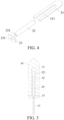
FIG. 3 is a schematic structural diagram of a susceptor inFIG. 2 . -
FIG. 4 is a schematic exploded view of parts of the susceptor shown inFIG. 3 . -
FIG. 5 is a schematic cross-sectional view of the susceptor inFIG. 2 in which a temperature sensor is encapsulated. -
FIG. 6 is a schematic diagram of a second part of a susceptor according to another embodiment. -
FIG. 7 is a schematic structural diagram of a susceptor according to another embodiment. -
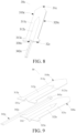
FIG. 8 is a schematic structural diagram of a susceptor according to another embodiment. -
FIG. 9 is a schematic exploded view of parts of the susceptor inFIG. 8 before assembly. -
FIG. 10 is a schematic structural diagram of a susceptor according to another embodiment. -
FIG. 11 is a schematic structural diagram of a susceptor according to another embodiment. -
FIG. 12 is a schematic structural diagram of a susceptor according to another embodiment. -
FIG. 13 is a schematic flowchart of a preparation method of a susceptor according to an embodiment. - For ease of understanding of this application, this application is described below in more detail with reference to accompanying drawings and specific implementations.
- Referring to
FIG. 2 , an aerosol generation device provided in an embodiment of this application includes: - a cavity that accommodates an inhalable material A, such as a cigarette, in a removable manner;
- an inductance coil L as a magnetic field generator, configured to generate an alternating magnetic field under an alternating current;
- a
susceptor 30, at least partially extending in the cavity and configured to be inductively coupled to the inductance coil L, where thesusceptor 30 is penetrated by the alternating magnetic field and generates heat to heat the inhalable material A, so that at least one component of the inhalable material A evaporates and forms an aerosol for inhaling; - a
core 10 that is a rechargeable direct-current core and can supply a direct-current voltage and a direct current; and - a
circuit 20 that is electrically connected to therechargeable core 10, and converts the direct current outputted by thecore 10 into an alternating current with a suitable frequency and supplies the alternating current to the inductance coil L. - According to settings in use of the device, the inductance coil L may include a cylindrical inductor coil wound into a spiral shape, as shown in
FIG. 2 . The cylindrical inductance coil L wound into the spiral shape may have a radius r ranging from about 5 mm to about 10 mm, and the radius r may be about 7 mm in particular. The cylindrical inductance coil L wound into the spiral shape may have a length ranging from about 8 mm to about 14 mm, and the number of turns of the inductance coil L may range from 8 to 15. Correspondingly, an inner volume may range from about 0.15 cm3 to about 1.10 cm3. - In a more exemplary implementation, a frequency of the alternating current supplied by the
circuit 20 to the inductance coil L ranges from 80 KHz to 400 KHz, and more specifically, the frequency may range from about 200 KHz to 300 KHz. - In an exemplary embodiment, the direct-current voltage supplied by the core 10 ranges from about 2.5 V to about 9.0 V, and the direct current supplied by the core 10 ranges from about 2.5 A to about 20 A.
- In an exemplary embodiment, the
susceptor 30 inFIG. 2 is made of a metal or an alloy material with an appropriate magnetic conductivity, so that when used, thesusceptor 30 can inductively generate heat corresponding to the magnetic field to heat the accommodated inhalable material A to generate the aerosol for inhaling. Thesusceptor 30 may be made of grade 420 stainless steel (SS420), and an alloy material (such as J85/J66 permalloy) containing iron and nickel. - In the embodiment shown in
FIG. 2 , the aerosol generation device further includes atubular holder 40 configured to arrange the inductance coil L and mount thesusceptor 30. Thetubular holder 40 may be made of a high-temperature resistant non-metal material, for example, PEEK, ceramic, or the like. During implementation, the inductance coil L is arranged on an outer wall of thetubular holder 40 in a spirally wound manner, and at least a part of thetubular holder 40 is internally hollow to form the cavity configured to accommodate the inhalable material A. - Referring to
FIG. 3 andFIG. 4 together, thesusceptor 30 includes: afirst part 31 constructed in a blade shape extending in an axial direction of the cavity, and asecond part 32 constructed to be a pin or in a needle shape extending in the axial direction of the cavity. In addition, during implementation, thefirst part 31 has avacancy 311 extending in the axial direction, and thesecond part 32 is held in thevacancy 311. During use, thefirst part 31 and thesecond part 32 may be simultaneously inserted into the inhalable material A and then heat the inhalable material A. - Referring to
FIG. 4 and FIG. 5 together, based on an idea of accurately detecting a temperature of thesusceptor 30, thesecond part 32 is a hollow structure in which anaccommodation cavity 321 extending in the axial direction is arranged. During use, theaccommodation cavity 321 is configured to accommodate and encapsulate atemperature sensor 50. Certainly, after fixed in theaccommodation cavity 321, the temperature sensor may be encapsulated inside thesecond part 32 by gluing, and the like, and is closely attached to an inner wall of thesecond part 32, so as to accurately detect a real-time operating temperature of thesusceptor 30. - Referring to
FIG. 3 andFIG. 4 again, for ease of mounting and fixing thesusceptor 30, the susceptor further includes abase part 33. Thefirst part 31, thesecond part 32, and thebase part 33 are fixed as an indivisible integral by soldering, interference fitting, or the like. During use, thebase part 33 is constructed into a plate perpendicular to thefirst part 31 and thesecond part 32, and has a size greater than that of thefirst part 31 and thesecond part 32, so as to be mounted and fixed in thetubular holder 40 by abutting, clamping, and the like. - Meanwhile, the
base part 33 has a throughhole 331 configured for aconductive pin 51 of thetemperature sensor 50 to run through and be exposed outside thesusceptor 30, so that theconductive pin 51 is electrically connected to thecircuit 20 to supply power and receive a sensing signal. - It may be learnt from
FIG. 3 andFIG. 4 that, a size of an outer diameter of thesecond part 32 is greater than a thickness of a sheet of the first part. Therefore, thesecond part 32 can protrude from two sides of thefirst part 31 in a thickness direction, so that thesusceptor 30 can have a relatively larger surface area to be in contact with the inhalable material A, thereby increasing the efficiency of heat transfer during heating. - In some embodiments, meanwhile, in order to avoid heat damage of the
tubular holder 40 caused by heat transfer from thebase part 33 to thetubular holder 40, thebase part 33 is made of a material with a low thermal conductivity, for example, zirconia ceramic, and the like. - In some embodiments, the
first part 31 and thesecond part 32 may be fixed by close fitting, and the like. - Referring to
FIG. 6 , in some embodiments, an outer surface of asecond part 32a is provided withgrooves 322a extending in the axial direction. Afirst part 31 may be integrated with thesecond part 32a by being embedded into thegrooves 322a to be clamped. - Referring to
FIG. 7 , in some embodiments, for ease of detaching and replacing a susceptor 30b, after a temperature sensor (encapsulated in thesusceptor 30b and not shown) is encapsulated in thesecond part 32a through a through hole 311b of abase part 33b, aconductive contact 51b which is exposed outside an outer surface of the susceptor 30b is formed on a surface of thebase part 33b by digital printing, analogue printing, depositing, or etching, and is configured to be connected to a pin of the temperature sensor by soldering, and the like. During use, thecircuit 20 may abut against theconductive contact 51b by a contact conductive mechanism such as a commonly used conductive elastic pin, to supply power to the temperature sensor or receive a sensing signal, so as to avoid inconvenience caused to the replacing and detaching of thesusceptor 30 by soldering the pin of the temperature sensor to thecircuit 20. - Referring to
FIG. 8 and FIG. 9 together, in some embodiments, asusceptor 30c is constructed into a blade shape, and has afirst end 31c and asecond end 32c. Thefirst end 31c is opposite to an opening of the cavity configured to accommodate the inhalable material A. During use, thefirst end 31c, as a free end, is constructed into a tip shape for being easily inserted into the inhalable material A that is accommodated in the cavity through an opening end. Thesecond end 32c, as an end portion for mounting and connecting, is configured to provide support through thetubular holder 40, so that thesusceptor 30c is stably held and fixedly mounted in the device. - In some implementations, the construction of the susceptor 30c is formed by a first sheet-
like object 310c and a second sheet-like object 320c that are opposite to each other in the thickness direction. Specifically, the first sheet-like object 310c includes a flat and straightfirst part 311c, asecond part 312c formed by thefirst part 311c protruding outward in the thickness direction, and athird part 313c formed by at least a part of thefirst part 311c close to thesecond end 32c extending in a width direction. Correspondingly, a shape of the second sheet-like object 320c is similar to that of the first sheet-like object 310c. The second sheet-like object 320c also has a flat and straightfourth part 321c, afifth part 322c formed by thefourth part 321c protruding outward in the thickness direction, and asixth part 323c formed by at least a part of thefourth part 321c close to thesecond end 32c extending in the width direction. After the first sheet-like object 310c and the second sheet-like object 320c are combined, anaccommodation cavity 330c configured to accommodate and encapsulate atemperature sensor 340c is formed between the two sheet-like objects. Specifically, theaccommodation cavity 330c is formed by a first recessedstructure 331 formed by thesecond part 312c of the first sheet-like object 310c, and a second recessed structure 332c formed by thefifth part 322c of the second sheet-like object 320c. - During assembling, a
sensing part 341c of thetemperature sensor 340c is accommodated and encapsulated in theaccommodation cavity 330c, and may be encapsulated and fixed by gluing, and the like. Meanwhile, an electrical connection part 342 of thetemperature sensor 340c is designed into a long and thin pin and runs through thesecond end 32c from theaccommodation cavity 330c to the outside of the susceptor 30c, so as to be conveniently connected to thecircuit 20. Then, thecircuit 20 may receive a sensing signal of thesensing part 341c through the electrical connection part 342. During use, thetemperature sensor 40 is encapsulated in theaccommodation cavity 330c that is overall insulated from a magnetic field. Thesensing part 341c closely abuts against the first sheet-like object 310c and/or the second sheet-like object 320c. In this way, a temperature of thesusceptor 30c can be detected stably or accurately while avoiding interference by the magnetic field. - Furthermore, the
temperature sensor 340c may be a thermistor temperature sensor that calculates the temperature by monitoring a change of resistance, for example, PT1000, or may be a thermocouple temperature sensor that calculates the temperature by calculating thermoelectromotive forces at two ends. - Based on an idea of mass production and preparation of the susceptor 30c, furthermore, in an exemplary implementation, the
second part 312c of the first sheet-like object 310c and/or thefifth part 322c of the second sheet-like object 320c are/is formed or prepared by stamping on the foregoing flat sheet-like sensing material, such as a sheet metal part. Meanwhile, in a stable connection, the first sheet-like object 310c and the second sheet-like object 320c may be integrated by soldering, such as, laser soldering, and the like. - In some embodiments, the
accommodation cavity 330c extends in an axial direction of the susceptor 30c. During implementation, a cross section of theaccommodation cavity 330c may generally be in a diamond shape, a circle shape, a square shape, or the like. - As shown in
FIG. 9 , thesecond part 321c has a conical part 312c1 that is close to thefirst end 31c of the susceptor 30c and whose cross-sectional area gradually decreases, for example, a circular cone, a triangular cone, or the like. The conical part 312c1 is configured to reduce resistance when inserted into the inhalable material A. - In some embodiments, the conical part 312c1 of the
second part 312c, together with the correspondingfifth part 322c that has a similar structure, may cause a front part of the formedaccommodation cavity 330c close to thefirst end 31c to be in a cone shape. During mounting, thesensing part 341c of thetemperature sensor 340c abuts against the cone-shaped front part of theaccommodation cavity 330c, for ease of close fitting and mounting. - According to the embodiment shown in the figure, in the
susceptor 30c, a size of theaccommodation cavity 330c formed by thesecond part 312c and thefifth part 322c in the thickness direction is greater than other part of the susceptor 30c. Meanwhile, a size of thickness of theaccommodation cavity 330c formed by thesecond part 312c and thefifth part 322c gradually increases inward in the width direction, so that an outer surface of the susceptor 30c formed by thesecond part 312c and thefifth part 322c gradually changes. On the one hand, a contact area with the inhalable material A is increased to improve the efficiency of heat transfer. On the other hand, the resistance is reduced when thesusceptor 30c is inserted into the inhalable material A. - Referring to
FIG. 10 and FIG. 11 together, in another embodiment, a second sheet-like object 320d/320e of asusceptor 30d/30e is flat and straight. Asecond part 312d/312e protruding outward in the thickness direction is formed only on the second sheet-like object 310d/310e by stamping, or the like. Anaccommodation cavity 330d/330e configured to accommodate or encapsulate a temperature sensor is formed between thesecond part 312d/312e and the second sheet-like object 320d/320e. - According to the embodiment shown in
FIG. 5 orFIG. 6 , a cross section of thesecond part 312d/312e may generally be in a triangle shape or a circular arc shape whose size of thickness gradually increases inward in the width direction. It may be seen fromFIG. 5 andFIG. 6 that a size of protruding of thesecond part 312d/312e in the thickness direction is greater than a size of thickness of afirst part 311 d/31 1e. - Referring to
FIG. 12 , in another embodiment, along asusceptor 30f, athird part 313f of a first sheet-like object 310f of thesusceptor 30f has a size of thickness greater than that of afirst part 311f and asecond part 312f. In this way, thethird part 313f protrudes relative to other parts in the thickness direction, so as to be easily mounted or held in the device. - The aerosol generation device and the susceptor of this application encapsulates or accommodates the temperature sensor in the susceptor. In this way, on the one hand, a sensing part may be basically insulated from the impact of the magnetic field, and on the other hand, the susceptor and the temperature sensor may be integrated to increase the stability of mounting and the accuracy of temperature detecting, and meanwhile, overall replacement and mounting are easier.
- This application further provides a method for preparing the foregoing
susceptor 30c. Referring toFIG. 13 , steps of the method include: - S10: Provide a first sheet-
like object 310c and a second sheet-like object 320c that are opposite to each other in a thickness direction; - S20: Form an
accommodation cavity 330c extending in a length direction between the first sheet-like object 310c and the second sheet-like object 320c; and - S30: Obtain a
temperature sensor 340c and accommodate or encapsulate thetemperature sensor 340c in theaccommodation cavity 330c. - It should be noted that, the specification of this application and the accompanying drawings thereof illustrate exemplary embodiments of this application, but this application is not limited to the embodiments described in this specification, furthermore, a person of ordinary skill in the art may make improvements or modifications according to the foregoing description, and all of the improvements and modifications should all fall within the protection scope of the attached claims of this application.
Claims (12)
- An aerosol generation device, configured to heat an inhalable material to generate an aerosol, the device comprising:a cavity, configured to accommodate the inhalable material;a magnetic field generator, configured to generate a changing magnetic field; anda susceptor, configured to be penetrated by the changing magnetic field and generate heat, to heat the inhalable material accommodated in the cavity, whereinthe susceptor is constructed in a blade shape extending in an axial direction of the cavity, and comprises:a first part, having a first size in a thickness direction of the susceptor; anda second part, having a second size in the thickness direction of the susceptor, the second size being greater than the first size, an accommodation cavity extending in the axial direction being arranged in the second part, and the accommodation cavity being configured to accommodate or encapsulate a temperature sensor that senses a temperature of the susceptor.
- The aerosol generation device according to claim 1, wherein the susceptor comprises a first sheet-like object and a second sheet-like object that are opposite to each other in the thickness direction, and the accommodation cavity is formed between the first sheet-like object and the second sheet-like object.
- The aerosol generation device according to claim 1 or 2, wherein the temperature sensor further comprises a conductive connection portion at least partially located outside the susceptor, to receive the temperature sensed by the temperature sensor through the conductive connection portion during use.
- The aerosol generation device according to claim 3, wherein the conductive connection portion comprises a long and thin conductive pin.
- The aerosol generation device according to claim 3, wherein the conductive connection portion comprises an electrical contact formed on or integrated into a surface of the susceptor.
- The aerosol generation device according to claim 5, wherein the susceptor further comprises a base part configured to hold the first part and the second part; and
the electrical contact is formed on or integrated into a surface of the base part. - The aerosol generation device according to claim 1 or 2, wherein the cavity has an opening end that receives the inhalable material in a removable manner; and
a protrusion height of at least a part of the second part relative to the first part gradually decreases in a direction close to the opening end. - The aerosol generation device according to claim 1 or 2, wherein the cavity has an opening end that receives the inhalable material in a removable manner;
the accommodation cavity comprises a conical region whose cross-sectional area gradually decreases in a direction close to the opening end; and the temperature sensor is accommodated or encapsulated in the conical region. - The aerosol generation device according to claim 1 or 2, wherein the first part is provided with a vacancy extending in a length direction; and the second part is constructed to be a pin or in a needle shape extending in the length direction, and is held in the vacancy.
- The aerosol generation device according to claim 1 or 2, wherein a surface of the second part is a smooth arc surface.
- The aerosol generation device according to claim 2, wherein the first sheet-like object and/or the second sheet-like object is provided with a protruding part protruding outward in the thickness direction, and the protruding part defines the accommodation cavity.
- A susceptor for an aerosol generation device, configured to be penetrated by a changing magnetic field and generate heat, to heat an inhalable material, wherein the susceptor is constructed in a blade shape extending in an axial direction of a cavity, and comprises:a first part, having a first size in a thickness direction of the susceptor; anda second part, having a second size in the thickness direction of the susceptor, the second size being greater than the first size, an accommodation cavity extending in the axial direction being arranged in the second part, and the accommodation cavity being configured to accommodate or encapsulate a temperature sensor that senses a temperature of the susceptor.
Applications Claiming Priority (3)
| Application Number | Priority Date | Filing Date | Title |
|---|---|---|---|
| CN202020796480.8U CN213344351U (en) | 2020-05-12 | 2020-05-12 | Aerosol generating device and sensor |
| CN202010451178.3A CN113712266A (en) | 2020-05-25 | 2020-05-25 | Aerosol-generating device, susceptor and method of making |
| PCT/CN2021/093418 WO2021228157A1 (en) | 2020-05-12 | 2021-05-12 | Aerosol generating device, and susceptor |
Publications (3)
| Publication Number | Publication Date |
|---|---|
| EP4151103A1 true EP4151103A1 (en) | 2023-03-22 |
| EP4151103A4 EP4151103A4 (en) | 2023-10-25 |
| EP4151103B1 EP4151103B1 (en) | 2024-04-10 |
Family
ID=78525326
Family Applications (1)
| Application Number | Title | Priority Date | Filing Date |
|---|---|---|---|
| EP21803080.7A Active EP4151103B1 (en) | 2020-05-12 | 2021-05-12 | Aerosol generating device, and susceptor |
Country Status (5)
| Country | Link |
|---|---|
| US (1) | US12446625B2 (en) |
| EP (1) | EP4151103B1 (en) |
| JP (1) | JP7488367B2 (en) |
| KR (1) | KR102872167B1 (en) |
| WO (1) | WO2021228157A1 (en) |
Cited By (1)
| Publication number | Priority date | Publication date | Assignee | Title |
|---|---|---|---|---|
| EP4136991A1 (en) * | 2021-08-17 | 2023-02-22 | Shenzhen Eigate Technology Co., Ltd. | Heating assembly comprising a high-frequency control assembly |
Families Citing this family (4)
| Publication number | Priority date | Publication date | Assignee | Title |
|---|---|---|---|---|
| GB202116980D0 (en) * | 2021-11-25 | 2022-01-12 | Nicoventures Trading Ltd | Apparatus for heating aerosol generating material |
| KR102936047B1 (en) * | 2022-05-13 | 2026-03-09 | 하이난 무어 브라더스 테크놀로지 컴퍼니 리미티드 | Electronic atomization device and heating assembly therefor |
| CN114983023A (en) * | 2022-05-18 | 2022-09-02 | 安徽中烟工业有限责任公司 | Modular combined device with induction coil and inductive heating body |
| USD1051071S1 (en) | 2022-11-07 | 2024-11-12 | Altria Client Services Llc | Set of electrical contact pads |
Family Cites Families (18)
| Publication number | Priority date | Publication date | Assignee | Title |
|---|---|---|---|---|
| ES2944585T3 (en) | 2014-05-21 | 2023-06-22 | Philip Morris Products Sa | Aerosol-generating article with internal susceptor |
| CN206808677U (en) | 2017-05-10 | 2017-12-29 | 深圳市合元科技有限公司 | Can temperature correction Electromagnetic Heating electronic cigarette |
| TW201902372A (en) * | 2017-05-31 | 2019-01-16 | 瑞士商菲利浦莫里斯製品股份有限公司 | Heating member of aerosol generating device |
| WO2019030168A1 (en) | 2017-08-09 | 2019-02-14 | Philip Morris Products S.A. | Aerosol-generating device with an induction heater with a conical induction coil |
| CN109805446B (en) * | 2017-11-22 | 2023-06-16 | 湖南中烟工业有限责任公司 | Magnetic induction atomizing device and magnetic induction heating suction device |
| CN208228311U (en) | 2018-04-10 | 2018-12-14 | 深圳市新宜康科技股份有限公司 | The heating of high-energy utilization rate not burner |
| CN207766584U (en) * | 2018-01-31 | 2018-08-24 | 深圳市合元科技有限公司 | A kind of heating device and electronic cigarette |
| WO2019199010A1 (en) | 2018-04-09 | 2019-10-17 | 주식회사 아모센스 | Heat generating heater for cigarette-type electronic cigarette device |
| CN208446607U (en) | 2018-04-24 | 2019-02-01 | 深圳市合元科技有限公司 | Heating device and electric heating smoking device |
| CN108903062A (en) | 2018-08-21 | 2018-11-30 | 威滔电子科技(深圳)有限公司 | A kind of heater and preparation method thereof, aerosol generating device |
| CN109077361A (en) * | 2018-09-21 | 2018-12-25 | 李东 | A heating component and electronic cigarette |
| CN209031260U (en) | 2018-09-21 | 2019-06-28 | 深圳麦克韦尔股份有限公司 | Smoking set and its heating element |
| JP7544717B2 (en) * | 2018-09-25 | 2024-09-03 | フィリップ・モーリス・プロダクツ・ソシエテ・アノニム | Heating assembly and method for inductively heating an aerosol-forming substrate - Patents.com |
| BR112021005112A2 (en) | 2018-09-25 | 2021-06-15 | Philip Morris Products S.A. | inductively heated aerosol generating device comprising a susceptor assembly |
| CN209931492U (en) * | 2019-03-14 | 2020-01-14 | 深圳市合元科技有限公司 | Heaters and low-temperature curing smoking sets |
| CN209931506U (en) | 2019-04-02 | 2020-01-14 | 惠州市沛格斯科技有限公司 | Heating assembly |
| CN212852505U (en) | 2020-05-25 | 2021-04-02 | 深圳市合元科技有限公司 | Aerosol generating device and sensor |
| CN212464915U (en) | 2020-08-12 | 2021-02-05 | 深圳市合元科技有限公司 | Aerosol generating device and susceptor |
-
2021
- 2021-05-12 US US17/925,007 patent/US12446625B2/en active Active
- 2021-05-12 WO PCT/CN2021/093418 patent/WO2021228157A1/en not_active Ceased
- 2021-05-12 JP JP2022568652A patent/JP7488367B2/en active Active
- 2021-05-12 KR KR1020227042631A patent/KR102872167B1/en active Active
- 2021-05-12 EP EP21803080.7A patent/EP4151103B1/en active Active
Cited By (1)
| Publication number | Priority date | Publication date | Assignee | Title |
|---|---|---|---|---|
| EP4136991A1 (en) * | 2021-08-17 | 2023-02-22 | Shenzhen Eigate Technology Co., Ltd. | Heating assembly comprising a high-frequency control assembly |
Also Published As
| Publication number | Publication date |
|---|---|
| JP7488367B2 (en) | 2024-05-21 |
| US20230180839A1 (en) | 2023-06-15 |
| KR102872167B1 (en) | 2025-10-15 |
| EP4151103A4 (en) | 2023-10-25 |
| WO2021228157A1 (en) | 2021-11-18 |
| EP4151103B1 (en) | 2024-04-10 |
| US12446625B2 (en) | 2025-10-21 |
| KR20230004873A (en) | 2023-01-06 |
| JP2023525110A (en) | 2023-06-14 |
Similar Documents
| Publication | Publication Date | Title |
|---|---|---|
| EP4151103B1 (en) | Aerosol generating device, and susceptor | |
| CN212852498U (en) | Sensor for aerosol-generating device, aerosol-generating device | |
| CN212464914U (en) | Susceptor for aerosol-generating device, aerosol-generating device and temperature measuring device | |
| KR102363814B1 (en) | Device for heating smokeable material | |
| EP4159056A1 (en) | Aerosol generating device and susceptor therefor | |
| JP2024001095A (en) | Heating element suitable for aerosolisable material | |
| EP4133956A1 (en) | Gas mist generation device and receptor | |
| CN112656033A (en) | Aerosol generating device, susceptor, and temperature monitoring method | |
| CN215347073U (en) | Gas mist generating device and heater for gas mist generating device | |
| EP4430968A1 (en) | Aerosol generating device, and heater of aerosol generating device | |
| WO2021073617A1 (en) | Gas mist generation device and receptor | |
| CN113017149A (en) | Susceptor for aerosol-generating device and aerosol-generating device | |
| CN212852505U (en) | Aerosol generating device and sensor | |
| WO2021115339A1 (en) | Susceptor for aerosol generation device and aerosol generation device | |
| WO2023051729A1 (en) | Aerosol generating device and heater for aerosol generating device | |
| CN213344351U (en) | Aerosol generating device and sensor | |
| CN216961533U (en) | Gas mist generating device and heater for gas mist generating device | |
| EP4223161A1 (en) | Sensor for aerosol generation apparatus, aerosol generation apparatus and temperature measurement apparatus | |
| CN215347064U (en) | Aerosol-generating device and susceptor for aerosol-generating device | |
| CN113712266A (en) | Aerosol-generating device, susceptor and method of making | |
| CN113576048B (en) | Sensors for aerosol generating devices, aerosol generating devices | |
| CN215347072U (en) | Aerosol-generating device and susceptor for aerosol-generating device | |
| JP7746394B2 (en) | Apparatus for heating aerosolizable materials | |
| US20240008540A1 (en) | Heater for use in aerosol generation device, and aerosol generation device | |
| CN112806610A (en) | Gas mist generating device and control method |
Legal Events
| Date | Code | Title | Description |
|---|---|---|---|
| STAA | Information on the status of an ep patent application or granted ep patent |
Free format text: STATUS: THE INTERNATIONAL PUBLICATION HAS BEEN MADE |
|
| PUAI | Public reference made under article 153(3) epc to a published international application that has entered the european phase |
Free format text: ORIGINAL CODE: 0009012 |
|
| STAA | Information on the status of an ep patent application or granted ep patent |
Free format text: STATUS: REQUEST FOR EXAMINATION WAS MADE |
|
| 17P | Request for examination filed |
Effective date: 20221207 |
|
| AK | Designated contracting states |
Kind code of ref document: A1 Designated state(s): AL AT BE BG CH CY CZ DE DK EE ES FI FR GB GR HR HU IE IS IT LI LT LU LV MC MK MT NL NO PL PT RO RS SE SI SK SM TR |
|
| DAV | Request for validation of the european patent (deleted) | ||
| DAX | Request for extension of the european patent (deleted) | ||
| A4 | Supplementary search report drawn up and despatched |
Effective date: 20230926 |
|
| RIC1 | Information provided on ipc code assigned before grant |
Ipc: A24F 40/20 20200101ALN20230920BHEP Ipc: A24F 40/51 20200101ALI20230920BHEP Ipc: A24F 40/46 20200101AFI20230920BHEP |
|
| GRAP | Despatch of communication of intention to grant a patent |
Free format text: ORIGINAL CODE: EPIDOSNIGR1 |
|
| STAA | Information on the status of an ep patent application or granted ep patent |
Free format text: STATUS: GRANT OF PATENT IS INTENDED |
|
| RIC1 | Information provided on ipc code assigned before grant |
Ipc: A24F 40/20 20200101ALN20231030BHEP Ipc: A24F 40/51 20200101ALI20231030BHEP Ipc: A24F 40/46 20200101AFI20231030BHEP |
|
| INTG | Intention to grant announced |
Effective date: 20231114 |
|
| GRAS | Grant fee paid |
Free format text: ORIGINAL CODE: EPIDOSNIGR3 |
|
| GRAA | (expected) grant |
Free format text: ORIGINAL CODE: 0009210 |
|
| STAA | Information on the status of an ep patent application or granted ep patent |
Free format text: STATUS: THE PATENT HAS BEEN GRANTED |
|
| AK | Designated contracting states |
Kind code of ref document: B1 Designated state(s): AL AT BE BG CH CY CZ DE DK EE ES FI FR GB GR HR HU IE IS IT LI LT LU LV MC MK MT NL NO PL PT RO RS SE SI SK SM TR |
|
| REG | Reference to a national code |
Ref country code: GB Ref legal event code: FG4D |
|
| REG | Reference to a national code |
Ref country code: CH Ref legal event code: EP |
|
| REG | Reference to a national code |
Ref country code: DE Ref legal event code: R096 Ref document number: 602021011731 Country of ref document: DE |
|
| REG | Reference to a national code |
Ref country code: IE Ref legal event code: FG4D |
|
| REG | Reference to a national code |
Ref country code: LT Ref legal event code: MG9D |
|
| REG | Reference to a national code |
Ref country code: NL Ref legal event code: MP Effective date: 20240410 |
|
| REG | Reference to a national code |
Ref country code: AT Ref legal event code: MK05 Ref document number: 1673931 Country of ref document: AT Kind code of ref document: T Effective date: 20240410 |
|
| PG25 | Lapsed in a contracting state [announced via postgrant information from national office to epo] |
Ref country code: NL Free format text: LAPSE BECAUSE OF FAILURE TO SUBMIT A TRANSLATION OF THE DESCRIPTION OR TO PAY THE FEE WITHIN THE PRESCRIBED TIME-LIMIT Effective date: 20240410 |
|
| PG25 | Lapsed in a contracting state [announced via postgrant information from national office to epo] |
Ref country code: NL Free format text: LAPSE BECAUSE OF FAILURE TO SUBMIT A TRANSLATION OF THE DESCRIPTION OR TO PAY THE FEE WITHIN THE PRESCRIBED TIME-LIMIT Effective date: 20240410 |
|
| PG25 | Lapsed in a contracting state [announced via postgrant information from national office to epo] |
Ref country code: IS Free format text: LAPSE BECAUSE OF FAILURE TO SUBMIT A TRANSLATION OF THE DESCRIPTION OR TO PAY THE FEE WITHIN THE PRESCRIBED TIME-LIMIT Effective date: 20240810 |
|
| PG25 | Lapsed in a contracting state [announced via postgrant information from national office to epo] |
Ref country code: BG Free format text: LAPSE BECAUSE OF FAILURE TO SUBMIT A TRANSLATION OF THE DESCRIPTION OR TO PAY THE FEE WITHIN THE PRESCRIBED TIME-LIMIT Effective date: 20240410 |
|
| PG25 | Lapsed in a contracting state [announced via postgrant information from national office to epo] |
Ref country code: HR Free format text: LAPSE BECAUSE OF FAILURE TO SUBMIT A TRANSLATION OF THE DESCRIPTION OR TO PAY THE FEE WITHIN THE PRESCRIBED TIME-LIMIT Effective date: 20240410 Ref country code: FI Free format text: LAPSE BECAUSE OF FAILURE TO SUBMIT A TRANSLATION OF THE DESCRIPTION OR TO PAY THE FEE WITHIN THE PRESCRIBED TIME-LIMIT Effective date: 20240410 |
|
| PG25 | Lapsed in a contracting state [announced via postgrant information from national office to epo] |
Ref country code: GR Free format text: LAPSE BECAUSE OF FAILURE TO SUBMIT A TRANSLATION OF THE DESCRIPTION OR TO PAY THE FEE WITHIN THE PRESCRIBED TIME-LIMIT Effective date: 20240711 |
|
| PG25 | Lapsed in a contracting state [announced via postgrant information from national office to epo] |
Ref country code: PT Free format text: LAPSE BECAUSE OF FAILURE TO SUBMIT A TRANSLATION OF THE DESCRIPTION OR TO PAY THE FEE WITHIN THE PRESCRIBED TIME-LIMIT Effective date: 20240812 |
|
| PG25 | Lapsed in a contracting state [announced via postgrant information from national office to epo] |
Ref country code: ES Free format text: LAPSE BECAUSE OF FAILURE TO SUBMIT A TRANSLATION OF THE DESCRIPTION OR TO PAY THE FEE WITHIN THE PRESCRIBED TIME-LIMIT Effective date: 20240410 |
|
| PG25 | Lapsed in a contracting state [announced via postgrant information from national office to epo] |
Ref country code: AT Free format text: LAPSE BECAUSE OF FAILURE TO SUBMIT A TRANSLATION OF THE DESCRIPTION OR TO PAY THE FEE WITHIN THE PRESCRIBED TIME-LIMIT Effective date: 20240410 |
|
| PG25 | Lapsed in a contracting state [announced via postgrant information from national office to epo] |
Ref country code: PL Free format text: LAPSE BECAUSE OF FAILURE TO SUBMIT A TRANSLATION OF THE DESCRIPTION OR TO PAY THE FEE WITHIN THE PRESCRIBED TIME-LIMIT Effective date: 20240410 |
|
| PG25 | Lapsed in a contracting state [announced via postgrant information from national office to epo] |
Ref country code: LV Free format text: LAPSE BECAUSE OF FAILURE TO SUBMIT A TRANSLATION OF THE DESCRIPTION OR TO PAY THE FEE WITHIN THE PRESCRIBED TIME-LIMIT Effective date: 20240410 |
|
| PG25 | Lapsed in a contracting state [announced via postgrant information from national office to epo] |
Ref country code: PT Free format text: LAPSE BECAUSE OF FAILURE TO SUBMIT A TRANSLATION OF THE DESCRIPTION OR TO PAY THE FEE WITHIN THE PRESCRIBED TIME-LIMIT Effective date: 20240812 Ref country code: PL Free format text: LAPSE BECAUSE OF FAILURE TO SUBMIT A TRANSLATION OF THE DESCRIPTION OR TO PAY THE FEE WITHIN THE PRESCRIBED TIME-LIMIT Effective date: 20240410 Ref country code: NO Free format text: LAPSE BECAUSE OF FAILURE TO SUBMIT A TRANSLATION OF THE DESCRIPTION OR TO PAY THE FEE WITHIN THE PRESCRIBED TIME-LIMIT Effective date: 20240710 Ref country code: LV Free format text: LAPSE BECAUSE OF FAILURE TO SUBMIT A TRANSLATION OF THE DESCRIPTION OR TO PAY THE FEE WITHIN THE PRESCRIBED TIME-LIMIT Effective date: 20240410 Ref country code: IS Free format text: LAPSE BECAUSE OF FAILURE TO SUBMIT A TRANSLATION OF THE DESCRIPTION OR TO PAY THE FEE WITHIN THE PRESCRIBED TIME-LIMIT Effective date: 20240810 Ref country code: HR Free format text: LAPSE BECAUSE OF FAILURE TO SUBMIT A TRANSLATION OF THE DESCRIPTION OR TO PAY THE FEE WITHIN THE PRESCRIBED TIME-LIMIT Effective date: 20240410 Ref country code: GR Free format text: LAPSE BECAUSE OF FAILURE TO SUBMIT A TRANSLATION OF THE DESCRIPTION OR TO PAY THE FEE WITHIN THE PRESCRIBED TIME-LIMIT Effective date: 20240711 Ref country code: FI Free format text: LAPSE BECAUSE OF FAILURE TO SUBMIT A TRANSLATION OF THE DESCRIPTION OR TO PAY THE FEE WITHIN THE PRESCRIBED TIME-LIMIT Effective date: 20240410 Ref country code: ES Free format text: LAPSE BECAUSE OF FAILURE TO SUBMIT A TRANSLATION OF THE DESCRIPTION OR TO PAY THE FEE WITHIN THE PRESCRIBED TIME-LIMIT Effective date: 20240410 Ref country code: BG Free format text: LAPSE BECAUSE OF FAILURE TO SUBMIT A TRANSLATION OF THE DESCRIPTION OR TO PAY THE FEE WITHIN THE PRESCRIBED TIME-LIMIT Effective date: 20240410 Ref country code: AT Free format text: LAPSE BECAUSE OF FAILURE TO SUBMIT A TRANSLATION OF THE DESCRIPTION OR TO PAY THE FEE WITHIN THE PRESCRIBED TIME-LIMIT Effective date: 20240410 Ref country code: RS Free format text: LAPSE BECAUSE OF FAILURE TO SUBMIT A TRANSLATION OF THE DESCRIPTION OR TO PAY THE FEE WITHIN THE PRESCRIBED TIME-LIMIT Effective date: 20240710 |
|
| REG | Reference to a national code |
Ref country code: CH Ref legal event code: PL |
|
| REG | Reference to a national code |
Ref country code: DE Ref legal event code: R097 Ref document number: 602021011731 Country of ref document: DE |
|
| PG25 | Lapsed in a contracting state [announced via postgrant information from national office to epo] |
Ref country code: DK Free format text: LAPSE BECAUSE OF FAILURE TO SUBMIT A TRANSLATION OF THE DESCRIPTION OR TO PAY THE FEE WITHIN THE PRESCRIBED TIME-LIMIT Effective date: 20240410 |
|
| PG25 | Lapsed in a contracting state [announced via postgrant information from national office to epo] |
Ref country code: LU Free format text: LAPSE BECAUSE OF NON-PAYMENT OF DUE FEES Effective date: 20240512 |
|
| PG25 | Lapsed in a contracting state [announced via postgrant information from national office to epo] |
Ref country code: EE Free format text: LAPSE BECAUSE OF FAILURE TO SUBMIT A TRANSLATION OF THE DESCRIPTION OR TO PAY THE FEE WITHIN THE PRESCRIBED TIME-LIMIT Effective date: 20240410 |
|
| PG25 | Lapsed in a contracting state [announced via postgrant information from national office to epo] |
Ref country code: CZ Free format text: LAPSE BECAUSE OF FAILURE TO SUBMIT A TRANSLATION OF THE DESCRIPTION OR TO PAY THE FEE WITHIN THE PRESCRIBED TIME-LIMIT Effective date: 20240410 |
|
| PG25 | Lapsed in a contracting state [announced via postgrant information from national office to epo] |
Ref country code: SK Free format text: LAPSE BECAUSE OF FAILURE TO SUBMIT A TRANSLATION OF THE DESCRIPTION OR TO PAY THE FEE WITHIN THE PRESCRIBED TIME-LIMIT Effective date: 20240410 Ref country code: RO Free format text: LAPSE BECAUSE OF FAILURE TO SUBMIT A TRANSLATION OF THE DESCRIPTION OR TO PAY THE FEE WITHIN THE PRESCRIBED TIME-LIMIT Effective date: 20240410 |
|
| PG25 | Lapsed in a contracting state [announced via postgrant information from national office to epo] |
Ref country code: SM Free format text: LAPSE BECAUSE OF FAILURE TO SUBMIT A TRANSLATION OF THE DESCRIPTION OR TO PAY THE FEE WITHIN THE PRESCRIBED TIME-LIMIT Effective date: 20240410 |
|
| PG25 | Lapsed in a contracting state [announced via postgrant information from national office to epo] |
Ref country code: SM Free format text: LAPSE BECAUSE OF FAILURE TO SUBMIT A TRANSLATION OF THE DESCRIPTION OR TO PAY THE FEE WITHIN THE PRESCRIBED TIME-LIMIT Effective date: 20240410 Ref country code: SK Free format text: LAPSE BECAUSE OF FAILURE TO SUBMIT A TRANSLATION OF THE DESCRIPTION OR TO PAY THE FEE WITHIN THE PRESCRIBED TIME-LIMIT Effective date: 20240410 Ref country code: RO Free format text: LAPSE BECAUSE OF FAILURE TO SUBMIT A TRANSLATION OF THE DESCRIPTION OR TO PAY THE FEE WITHIN THE PRESCRIBED TIME-LIMIT Effective date: 20240410 Ref country code: LU Free format text: LAPSE BECAUSE OF NON-PAYMENT OF DUE FEES Effective date: 20240512 Ref country code: EE Free format text: LAPSE BECAUSE OF FAILURE TO SUBMIT A TRANSLATION OF THE DESCRIPTION OR TO PAY THE FEE WITHIN THE PRESCRIBED TIME-LIMIT Effective date: 20240410 Ref country code: DK Free format text: LAPSE BECAUSE OF FAILURE TO SUBMIT A TRANSLATION OF THE DESCRIPTION OR TO PAY THE FEE WITHIN THE PRESCRIBED TIME-LIMIT Effective date: 20240410 Ref country code: CZ Free format text: LAPSE BECAUSE OF FAILURE TO SUBMIT A TRANSLATION OF THE DESCRIPTION OR TO PAY THE FEE WITHIN THE PRESCRIBED TIME-LIMIT Effective date: 20240410 Ref country code: MC Free format text: LAPSE BECAUSE OF FAILURE TO SUBMIT A TRANSLATION OF THE DESCRIPTION OR TO PAY THE FEE WITHIN THE PRESCRIBED TIME-LIMIT Effective date: 20240410 Ref country code: CH Free format text: LAPSE BECAUSE OF NON-PAYMENT OF DUE FEES Effective date: 20240531 |
|
| PG25 | Lapsed in a contracting state [announced via postgrant information from national office to epo] |
Ref country code: IT Free format text: LAPSE BECAUSE OF FAILURE TO SUBMIT A TRANSLATION OF THE DESCRIPTION OR TO PAY THE FEE WITHIN THE PRESCRIBED TIME-LIMIT Effective date: 20240410 |
|
| PLBE | No opposition filed within time limit |
Free format text: ORIGINAL CODE: 0009261 |
|
| STAA | Information on the status of an ep patent application or granted ep patent |
Free format text: STATUS: NO OPPOSITION FILED WITHIN TIME LIMIT |
|
| REG | Reference to a national code |
Ref country code: BE Ref legal event code: MM Effective date: 20240531 |
|
| 26N | No opposition filed |
Effective date: 20250113 |
|
| P01 | Opt-out of the competence of the unified patent court (upc) registered |
Free format text: CASE NUMBER: APP_11096/2025 Effective date: 20250306 |
|
| PG25 | Lapsed in a contracting state [announced via postgrant information from national office to epo] |
Ref country code: IE Free format text: LAPSE BECAUSE OF NON-PAYMENT OF DUE FEES Effective date: 20240512 |
|
| PG25 | Lapsed in a contracting state [announced via postgrant information from national office to epo] |
Ref country code: SI Free format text: LAPSE BECAUSE OF FAILURE TO SUBMIT A TRANSLATION OF THE DESCRIPTION OR TO PAY THE FEE WITHIN THE PRESCRIBED TIME-LIMIT Effective date: 20240410 Ref country code: BE Free format text: LAPSE BECAUSE OF NON-PAYMENT OF DUE FEES Effective date: 20240531 |
|
| PGFP | Annual fee paid to national office [announced via postgrant information from national office to epo] |
Ref country code: DE Payment date: 20250513 Year of fee payment: 5 |
|
| PGFP | Annual fee paid to national office [announced via postgrant information from national office to epo] |
Ref country code: GB Payment date: 20250521 Year of fee payment: 5 |
|
| PGFP | Annual fee paid to national office [announced via postgrant information from national office to epo] |
Ref country code: FR Payment date: 20250530 Year of fee payment: 5 |
|
| PG25 | Lapsed in a contracting state [announced via postgrant information from national office to epo] |
Ref country code: CY Free format text: LAPSE BECAUSE OF FAILURE TO SUBMIT A TRANSLATION OF THE DESCRIPTION OR TO PAY THE FEE WITHIN THE PRESCRIBED TIME-LIMIT; INVALID AB INITIO Effective date: 20210512 |
|
| PG25 | Lapsed in a contracting state [announced via postgrant information from national office to epo] |
Ref country code: HU Free format text: LAPSE BECAUSE OF FAILURE TO SUBMIT A TRANSLATION OF THE DESCRIPTION OR TO PAY THE FEE WITHIN THE PRESCRIBED TIME-LIMIT; INVALID AB INITIO Effective date: 20210512 |
|
| PG25 | Lapsed in a contracting state [announced via postgrant information from national office to epo] |
Ref country code: SE Free format text: LAPSE BECAUSE OF FAILURE TO SUBMIT A TRANSLATION OF THE DESCRIPTION OR TO PAY THE FEE WITHIN THE PRESCRIBED TIME-LIMIT Effective date: 20240410 |