EP4150287B1 - Safety assembly - Google Patents
Safety assembly Download PDFInfo
- Publication number
- EP4150287B1 EP4150287B1 EP21729912.2A EP21729912A EP4150287B1 EP 4150287 B1 EP4150287 B1 EP 4150287B1 EP 21729912 A EP21729912 A EP 21729912A EP 4150287 B1 EP4150287 B1 EP 4150287B1
- Authority
- EP
- European Patent Office
- Prior art keywords
- laser
- directed energy
- energy weapon
- light beam
- photodetector
- Prior art date
- Legal status (The legal status is an assumption and is not a legal conclusion. Google has not performed a legal analysis and makes no representation as to the accuracy of the status listed.)
- Active
Links
Images




Classifications
-
- F—MECHANICAL ENGINEERING; LIGHTING; HEATING; WEAPONS; BLASTING
- F41—WEAPONS
- F41H—ARMOUR; ARMOURED TURRETS; ARMOURED OR ARMED VEHICLES; MEANS OF ATTACK OR DEFENCE, e.g. CAMOUFLAGE, IN GENERAL
- F41H13/00—Means of attack or defence not otherwise provided for
- F41H13/0043—Directed energy weapons, i.e. devices that direct a beam of high energy content toward a target for incapacitating or destroying the target
- F41H13/005—Directed energy weapons, i.e. devices that direct a beam of high energy content toward a target for incapacitating or destroying the target the high-energy beam being a laser beam
- F41H13/0062—Directed energy weapons, i.e. devices that direct a beam of high energy content toward a target for incapacitating or destroying the target the high-energy beam being a laser beam causing structural damage to the target
-
- F—MECHANICAL ENGINEERING; LIGHTING; HEATING; WEAPONS; BLASTING
- F41—WEAPONS
- F41A—FUNCTIONAL FEATURES OR DETAILS COMMON TO BOTH SMALLARMS AND ORDNANCE, e.g. CANNONS; MOUNTINGS FOR SMALLARMS OR ORDNANCE
- F41A17/00—Safety arrangements, e.g. safeties
- F41A17/06—Electric or electromechanical safeties
- F41A17/063—Electric or electromechanical safeties comprising a transponder
-
- F—MECHANICAL ENGINEERING; LIGHTING; HEATING; WEAPONS; BLASTING
- F41—WEAPONS
- F41A—FUNCTIONAL FEATURES OR DETAILS COMMON TO BOTH SMALLARMS AND ORDNANCE, e.g. CANNONS; MOUNTINGS FOR SMALLARMS OR ORDNANCE
- F41A17/00—Safety arrangements, e.g. safeties
- F41A17/08—Safety arrangements, e.g. safeties for inhibiting firing in a specified direction, e.g. at a friendly person or at a protected area
-
- F—MECHANICAL ENGINEERING; LIGHTING; HEATING; WEAPONS; BLASTING
- F41—WEAPONS
- F41G—WEAPON SIGHTS; AIMING
- F41G3/00—Aiming or laying means
- F41G3/26—Teaching or practice apparatus for gun-aiming or gun-laying
-
- F—MECHANICAL ENGINEERING; LIGHTING; HEATING; WEAPONS; BLASTING
- F41—WEAPONS
- F41G—WEAPON SIGHTS; AIMING
- F41G3/00—Aiming or laying means
- F41G3/26—Teaching or practice apparatus for gun-aiming or gun-laying
- F41G3/2616—Teaching or practice apparatus for gun-aiming or gun-laying using a light emitting device
- F41G3/2622—Teaching or practice apparatus for gun-aiming or gun-laying using a light emitting device for simulating the firing of a gun or the trajectory of a projectile
- F41G3/2683—Teaching or practice apparatus for gun-aiming or gun-laying using a light emitting device for simulating the firing of a gun or the trajectory of a projectile with reflection of the beam on the target back to the weapon
-
- F—MECHANICAL ENGINEERING; LIGHTING; HEATING; WEAPONS; BLASTING
- F41—WEAPONS
- F41H—ARMOUR; ARMOURED TURRETS; ARMOURED OR ARMED VEHICLES; MEANS OF ATTACK OR DEFENCE, e.g. CAMOUFLAGE, IN GENERAL
- F41H13/00—Means of attack or defence not otherwise provided for
- F41H13/0043—Directed energy weapons, i.e. devices that direct a beam of high energy content toward a target for incapacitating or destroying the target
- F41H13/005—Directed energy weapons, i.e. devices that direct a beam of high energy content toward a target for incapacitating or destroying the target the high-energy beam being a laser beam
-
- H—ELECTRICITY
- H01—ELECTRIC ELEMENTS
- H01S—DEVICES USING THE PROCESS OF LIGHT AMPLIFICATION BY STIMULATED EMISSION OF RADIATION [LASER] TO AMPLIFY OR GENERATE LIGHT; DEVICES USING STIMULATED EMISSION OF ELECTROMAGNETIC RADIATION IN WAVE RANGES OTHER THAN OPTICAL
- H01S5/00—Semiconductor lasers
- H01S5/0014—Measuring characteristics or properties thereof
- H01S5/0028—Laser diodes used as detectors
-
- F—MECHANICAL ENGINEERING; LIGHTING; HEATING; WEAPONS; BLASTING
- F41—WEAPONS
- F41A—FUNCTIONAL FEATURES OR DETAILS COMMON TO BOTH SMALLARMS AND ORDNANCE, e.g. CANNONS; MOUNTINGS FOR SMALLARMS OR ORDNANCE
- F41A33/00—Adaptations for training; Gun simulators
- F41A33/02—Light- or radiation-emitting guns ; Light- or radiation-sensitive guns; Cartridges carrying light emitting sources, e.g. laser
-
- F—MECHANICAL ENGINEERING; LIGHTING; HEATING; WEAPONS; BLASTING
- F41—WEAPONS
- F41G—WEAPON SIGHTS; AIMING
- F41G3/00—Aiming or laying means
- F41G3/26—Teaching or practice apparatus for gun-aiming or gun-laying
- F41G3/2616—Teaching or practice apparatus for gun-aiming or gun-laying using a light emitting device
- F41G3/2622—Teaching or practice apparatus for gun-aiming or gun-laying using a light emitting device for simulating the firing of a gun or the trajectory of a projectile
- F41G3/2655—Teaching or practice apparatus for gun-aiming or gun-laying using a light emitting device for simulating the firing of a gun or the trajectory of a projectile in which the light beam is sent from the weapon to the target
-
- F—MECHANICAL ENGINEERING; LIGHTING; HEATING; WEAPONS; BLASTING
- F41—WEAPONS
- F41G—WEAPON SIGHTS; AIMING
- F41G3/00—Aiming or laying means
- F41G3/32—Devices for testing or checking
-
- F—MECHANICAL ENGINEERING; LIGHTING; HEATING; WEAPONS; BLASTING
- F41—WEAPONS
- F41J—TARGETS; TARGET RANGES; BULLET CATCHERS
- F41J2/00—Reflecting targets, e.g. radar-reflector targets; Active targets transmitting electromagnetic or acoustic waves
- F41J2/02—Active targets transmitting infrared radiation
Definitions
- the present invention concerns laser-directed energy weapon safety systems and methods of preventing firing of laser-directed energy weapons as for instance described in US2020033458 A .
- the switch-off time of the weapon should be as fast as possible.
- US2002045999 discloses a method and apparatus for firing simulation.
- a first laser beam comprising laser pulses is transmitted through the actuation of the trigger on the gun, the trajectory of the fired virtual projectile is calculated, and the deviations from the target direction at the firing time are determined.
- US2018136364 discloses a light curtain safety system arranged to detect when an obstacle is in or near a light-of-sight power transmission path.
- Switch-off methods necessitate large buffer regions (due to the combination of a long switch-off period and a high tracking system slew rate) between the permitted firing region and any no-fire zone.
- additional buffer angles are required to accommodate for the maximum movement of the platform.
- the ship roll and pitch depends on the sea state, which makes beam control in elevation and avoidance of collateral assets such as aircraft and satellites extremely challenging, especially during weapon training.
- a laser-directed energy weapon safety system comprising a laser-directed energy weapon (4) and a safety assembly for use with the laser-directed energy weapon, the safety assembly comprising: a control system comprising a photodetector and a processing unit; an optical device configured to attach to a target such that, when attached, the optical device provides a light beam to the photodetector; the processing unit being arranged to compare the received light beam against one or more predetermined attributes, and to permit the laser-directed energy weapon to fire only when the received light beam is determined to have the one or more attributes.
- the one or more attributes may include a modulation signal, for example a frequency modulation signal.
- the one or more attributes may include receipt of a light beam of a particular colour.
- a colour filter may be used such that only light of a particular colour can reach the photodetector.
- the one or more attributes may essentially be the receipt of the light beam.
- the one or more attributes may include a light pattern, or any other properties of an optical signal which can distinguish the received light beam.
- the present safety beacon enables a firing region to be defined very precisely through high integrity confirmation of pointing, therefore reducing the risk of bodily harm or other damage in training and/or testing exercises.
- the safety assembly instigates shutdown in the absence of determination of the expected attributes, which may include the total absence of the light beam altogether, or loss of the light beam (after an earlier positive determination), and/or a mismatch between the detected and expected signals.
- the safety assembly therefore accommodates scenarios in which pointing is not confirmed, and scenarios in which pointing is confirmed and subsequently lost.
- the present safety beacon is suitable for use with the combination of a moving platform and a moving target, in addition to static platforms and targets.
- the processing unit may be arranged to prevent the laser-directed energy weapon from firing when no light beam is received.
- a safety assembly requires positive confirmation of permission to fire, with a default position of no-fire, thus improving safety in use.
- the optical device may be configured to provide a light beam continuously to the photodetector.
- a safety assembly may enable continuous, almost instantaneous feedback from the target to confirm its position relative to the laser-directed energy weapon in real-time, further improving precision of firing, and preventing shut-off delays.
- the optical device may comprise a light source.
- a light source may provide high spatial resolution, and therefore improved precision, compared to a sound wave or other source.
- the light source may be a laser diode.
- a laser diode may be particularly suitable for providing optical feedback over distances of several kilometres (even up to hundreds of kilometres) typically used in training and/or testing exercises.
- the laser diode may be configured to emit a frequency modulated light beam.
- the frequency modulated light beam may be modulated using the known reference signal. Alternatively some other modulation scheme may be used, as long as it is known to the control system.
- the processing unit may be arranged to demodulate the light beam received by the photodetector. Such an arrangement may facilitate a comparison between the received and expected signals. Alternatively, signal processing may be undertaken in an external unit.
- the laser diode may be configured to emit light with a modulation frequency in excess of 100Hz, for example in excess of 1000Hz.
- a modulation frequency may negate the effects of atmospheric turbulence (the effects of thermal eddies on refractive index), improving reliability of the safety assembly.
- the laser diode may be configured such that in use, the emitted light has a wavelength distinct from the wavelengths of a main laser comprised in the laser-directed energy weapon. Such a feature may ensure integrity of measurement, and avoid interference.
- the optical device may be configured to provide a wide-angle light beam.
- the wide-angle light beam may have a broad cone shape, for example defined by a diversion angle of greater than 45 degrees, more preferably greater than 60 degrees.
- the broad cone shape may be provided for example, by a single laser diode and a diverging lens, or via multiple laser diodes in different orientations.
- a wide-angle light beam advantageously maximises the chances of the feedback signal from the target being detected by the control system, thus improving the chances of an accurate determination (improving usability).
- the control system may comprise one or more dichroic mirrors.
- Dichroic mirrors may advantageously allow passage of light of only specific wavelengths, reflecting others. Such an arrangement may be useful for providing a safety assembly co-boresighted with the pointing system.
- the dichroic mirrors may not be present in the control system, with alternative optical components provided, or the dichroic mirrors forming part of the established pointing system of the laser-directed energy weapon.
- the processing unit may be arranged to output a PERMIT signal upon determining that the received light beam has the one or more attributes and to not output a PERMIT signal in the absence of such a determination.
- the PERMIT signal may be output (directly or indirectly) to the high-energy laser of the laser-directed energy weapon.
- the absence of a positive determination may indicate loss of pointing, or a total failure to establish pointing.
- Such a feature may improve safety and reliability, since the default position is no fire.
- the signal processing and output of the PERMIT signal may be undertaken in conjunction with an external control unit.
- the processing unit may be arranged to output an INHIBIT signal in the absence of such a determination.
- the INHIBIT signal may be output to the high-energy laser of the laser-directed energy weapon.
- the signal processing and output of the INHIBIT signal may be undertaken in conjunction with an external control unit.
- the control system may further comprise an aperture arranged with respect to the photodetector to constrict the photodetector field of view.
- the aperture size may be set upon manufacture and installation. Alternatively, the aperture size may be adjustable by an operator during use, to alter the field of view.
- the safety assembly may be configured to attach to the laser-directed energy weapon, such that when attached, the photodetector field of view aligns with the laser-directed energy weapon boresight.
- Such a co-boresight may minimise required modifications and enable re-use of existing components, thus reducing weight and complexity overall.
- the safety assembly may comprise a radio frequency emitter associated with the control system, and a radio frequency receiver associated with the optical device, the radio frequency emitter and receiver being arranged in use to emit and receive respectively a specific frequency signal, wherein in the absence of receipt of the specific frequency signal the light source is disabled.
- Such a feature may provide a high-integrity switching system, such that even upon correct confirmation of pointing, the laser-directed energy weapon can be prevented from firing. Therefore, safety may be improved, and or the system may be more versatile.
- the safety assembly may further comprise the target.
- a method of preventing firing of a laser-directed energy weapon including the steps of: attaching an optical device to a target; attaching a photodetector to the laser-directed energy weapon; providing a light beam from the optical device to the photodetector; comparing the light beam received by the photodetector against one or more attributes; wherein only upon determining that the light beam has the one or more attributes, permitting the laser-directed energy weapon to fire.
- the step of permitting the laser-directed energy weapon to fire may comprise outputting a PERMIT signal from the processing unit.
- the PERMIT signal may be output (directly or indirectly) to the high-energy laser to permit it to fire.
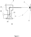
- a laser-directed energy weapon safety system comprising a laser-directed energy weapon (4) and a safety assembly 1 according to the first example embodiment of the invention is shown in Figure 1 .
- the safety assembly 1 is integrated in the laser-directed energy weapon 4.
- the safety assembly 1 is turned on via a manually operated switch (not shown) when it is required to test the laser-directed energy weapon or use it in training. Otherwise, in a combat scenario, the safety assembly 1 is turned off, and the laser-directed energy weapon 4 operates as normal, as if the safety assembly 1 were not present.
- the safety assembly 1 comprises an optical device 2, and a control system 3.
- the control system 3 includes optical components 11 and a processing unit 15.
- the optical device 2 is attached to a target 5.
- the target 5 is typically positioned several kilometres away from the laser-directed energy weapon 4, but may be used tens or hundreds of kilometres away.
- the laser-directed energy weapon 4 has a standard construction, including a tracking system (not shown) and a pointing system 21, and suitable fixings for attaching to a platform (not shown) such as an aircraft or ship.
- the pointing system 21 includes a high-energy laser 18 which fires towards the target 5.
- both of the platform (not shown) and the target 5 are dynamic.
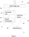
- the safety assembly 1 includes a control system 3 and an optical device ( Figure 2 ).
- the safety assembly 1 also includes a switching system 13.
- the optical device 2 is used to provide feedback to the control system 3 regarding the position of the target 5, so that pointing direction can be verified prior to the high-energy laser 18 firing.
- the optical device 2 provides a light beam 29 to the control system 3 which is received by optical components 11.
- a signal 37 is output from the optical components 11 to the processing unit 15.
- the processing unit 15 then processes the signal 37 and compares it against one or more previously determined attributes (in the present example embodiment the one or more previously determined attributes is a known frequency modulation signal), and outputs a PERMIT or INHIBIT signal 16 based on the result of the comparison to the high-energy laser 18, to permit or prevent it from firing a high-energy laser beam 8.
- the switching system 13 is used to indirectly control the high-energy laser 18 by providing a radio-frequency signal 52 to the optical device 2, which enables or disables the optical device 2 depending on whether or not the signal 52 is determined to have a certain expected frequency.
- the optical components 11 are arranged ( Figure 3 ) to align with the pointing system 21.
- the pointing system 21 includes the high-power laser 18 and a first dichroic mirror 19.
- the pointing system 21 emits the high-energy laser beam 8 towards a first dichroic mirror 19.
- the first dichroic mirror 19 is angled with respect to the high-power laser 18 to reflect the high-energy laser beam 8 along the pointing system boresight 23.
- a pointing mirror 25 in the path of the high-energy laser beam 8 directs the high-energy laser beam 8 towards the target 5 via a lens 27.
- the high-energy laser beam 8 is emitted from the pointing system 21 towards the target 5.
- the optical device 2 in the first example embodiment of the invention is a laser diode, attached to the target 5 and arranged to emit a laser beam 29. Whilst during combat, such a marking/modification of a target would not be possible, in a training or testing scenario where additional safety measures are required, the target 5 can be set up prior to firing the high-energy laser 18.
- the optical components 11 ( Figure 3 ) in the control system 3 of the safety assembly 1 are arranged in line with the pointing system 21, and include a photodetector 35, aperture 33 and second dichroic mirror 31.
- the photodetector 35 field of view is co-boresighted with the pointing system 21.
- the focussing lens 27 focusses the laser beam 29 emitted by the laser diode 2 on the pointing mirror 25 of the pointing system 21.
- the laser beam 29 is reflected by the pointing mirror 25 along the pointing system boresight 23 in the direction of the first dichroic mirror 19.
- the laser beam 29 has a different wavelength to the high-energy laser beam 8 and is not reflected by the first dichroic mirror 19 but instead passes through it, towards the optical components 11 of the control system 3.
- the laser beam 29 is then reflected by the second dichroic mirror 31 arranged to reflect the laser beam 29 through the aperture 33 to the photodetector 35.
- the photodetector 35 then outputs the corresponding signal 37 to the processing unit 15 (not shown).
- the optical device 2 is a laser diode, any suitable light source may be used.
- the light emitted by the laser diode 2 is pulsed using a known reference signal 36 (i.e. it is frequency modulated).
- a known reference signal 36 i.e. it is frequency modulated.
- a single frequency is used, however in other embodiments a multiple frequency reference signal may be used.
- the laser diode 55a is arranged along the pointing system 21a boresight 23a such that the laser beam 29a passes through the second 31a and first 19a dichroic mirrors respectively, before being reflected by the pointing mirror 25a, out towards the target 5a.
- the safety assembly 1a operates in a similar manner to the safety assembly 1 of the first example embodiment of the invention except that the laser diode light beam 29a originates within the control system and is reflected from the target 5a, before being detected by the photodetector 35a.
- the arrangement of the second example embodiment of the invention may provide the benefit of retaining all active components within the control system (attached to the laser-directed energy weapon) for easier access.
- the broad light beam is provided through a combination of a wide emitted beam angle from the laser diode 55a and the reflecting surface of the retroreflector 2a.
- the required buffer zones around the permitted firing arc are greatly reduced, since the removal of the PERMIT signal is almost instantaneous (leading to a reduced error margin). Therefore, the firing arcs (made up of the permitted firing arc and buffer zones) can be much smaller than possible using laser-directed energy weapon safety systems of the prior art, and multiple firing arcs can also be simulated.
- some other "key” may be used, such as a specific colour of light, or light pattern.
- the "key” must transmit with high spatial resolution i.e. sound waves are unsuitable due to their divergence.
- a laser diode instead of a laser diode, there may be an alternative light source.
- a light-emitting diode may be suitable.
Landscapes
- Engineering & Computer Science (AREA)
- General Engineering & Computer Science (AREA)
- Radar, Positioning & Navigation (AREA)
- Physics & Mathematics (AREA)
- Optics & Photonics (AREA)
- Remote Sensing (AREA)
- Electromagnetism (AREA)
- Condensed Matter Physics & Semiconductors (AREA)
- General Physics & Mathematics (AREA)
- Optical Radar Systems And Details Thereof (AREA)
- Aiming, Guidance, Guns With A Light Source, Armor, Camouflage, And Targets (AREA)
- Laser Beam Processing (AREA)
- Photometry And Measurement Of Optical Pulse Characteristics (AREA)
Description
- The present invention concerns laser-directed energy weapon safety systems and methods of preventing firing of laser-directed energy weapons as for instance described in
US2020033458 A . - During testing of laser-directed energy weapons or during operator training, it is important to constrain the high-energy laser radiation emitted by the weapon to a precisely defined area to prevent unwanted burns, or other harm. It is also important to minimise the time period between instigating switch-off of the laser-directed energy weapon, and switch-off occurring, to prevent damaging effects occurring after switch-off has been initiated. In other words, the switch-off time of the weapon should be as fast as possible.
- For static targets, there are several known ways of constraining a laser-directed energy weapon laser beam to a well-defined area, including using physically restrained pointing systems (e.g. gimbal system end-stops), placing large backstops behind the targets or using letterbox apertures to constrain the beam path. These methods are generally unsuitable for moving targets, and are particularly unsuitable for moving targets engaged from moving platforms due to the uncertainties (i.e. the error margins) introduced by the relative motion of the target and platform.
-
US2002045999 discloses a method and apparatus for firing simulation. In the method for firing simulation with a fun, to attain greater ranges, a first laser beam comprising laser pulses is transmitted through the actuation of the trigger on the gun, the trajectory of the fired virtual projectile is calculated, and the deviations from the target direction at the firing time are determined. -
US2018136364 discloses a light curtain safety system arranged to detect when an obstacle is in or near a light-of-sight power transmission path. - There is a need for an improved means of constraining a laser-directed energy weapon laser beam to a well-defined area, or otherwise verifying pointing direction with high precision.
- Traditional switch-off methods necessitate large buffer regions (due to the combination of a long switch-off period and a high tracking system slew rate) between the permitted firing region and any no-fire zone. For moving platforms, additional buffer angles are required to accommodate for the maximum movement of the platform. For example in maritime systems, the ship roll and pitch depends on the sea state, which makes beam control in elevation and avoidance of collateral assets such as aircraft and satellites extremely challenging, especially during weapon training.
- The requirement for large buffer regions makes many scenarios impossible, leading to a system under test or training that is not representative of the in-service use case.
- There is therefore also a need for an improved means of switching off a laser-directed energy weapon.
- In summary, there is a need for a new laser-directed energy weapon safety system or method of use, which overcomes the aforementioned drawbacks and/or provides high integrity confirmation and control of pointing and improved safety during testing and training operations.
- In a first aspect of the invention there is provided a laser-directed energy weapon safety system comprising a laser-directed energy weapon (4) and a safety assembly for use with the laser-directed energy weapon, the safety assembly comprising: a control system comprising a photodetector and a processing unit; an optical device configured to attach to a target such that, when attached, the optical device provides a light beam to the photodetector; the processing unit being arranged to compare the received light beam against one or more predetermined attributes, and to permit the laser-directed energy weapon to fire only when the received light beam is determined to have the one or more attributes.
- The one or more attributes may include a modulation signal, for example a frequency modulation signal. The one or more attributes may include receipt of a light beam of a particular colour. In that example, a colour filter may be used such that only light of a particular colour can reach the photodetector. In such a case, the one or more attributes may essentially be the receipt of the light beam. The one or more attributes may include a light pattern, or any other properties of an optical signal which can distinguish the received light beam.
- Compared to safety systems of the prior art, the present safety beacon enables a firing region to be defined very precisely through high integrity confirmation of pointing, therefore reducing the risk of bodily harm or other damage in training and/or testing exercises. The safety assembly instigates shutdown in the absence of determination of the expected attributes, which may include the total absence of the light beam altogether, or loss of the light beam (after an earlier positive determination), and/or a mismatch between the detected and expected signals. The safety assembly therefore accommodates scenarios in which pointing is not confirmed, and scenarios in which pointing is confirmed and subsequently lost.
- Unlike safety systems of the prior art, the present safety beacon is suitable for use with the combination of a moving platform and a moving target, in addition to static platforms and targets.
- The processing unit may be arranged to prevent the laser-directed energy weapon from firing when no light beam is received. Such a safety assembly requires positive confirmation of permission to fire, with a default position of no-fire, thus improving safety in use.
- The optical device may be configured to provide a light beam continuously to the photodetector. Such a safety assembly may enable continuous, almost instantaneous feedback from the target to confirm its position relative to the laser-directed energy weapon in real-time, further improving precision of firing, and preventing shut-off delays.
- The optical device may comprise a light source. A light source may provide high spatial resolution, and therefore improved precision, compared to a sound wave or other source.
- The optical device may comprise a retro-reflector, and the control system may comprise a light source, wherein when attached to the target, the optical device provides a reflected light beam to the photodetector. In such a safety assembly, the active components may be co-located in one, easily accessible place.
- The light source may be a laser diode. A laser diode may be particularly suitable for providing optical feedback over distances of several kilometres (even up to hundreds of kilometres) typically used in training and/or testing exercises.
- The laser diode may be configured to emit a frequency modulated light beam. The frequency modulated light beam may be modulated using the known reference signal. Alternatively some other modulation scheme may be used, as long as it is known to the control system.
- The processing unit may be arranged to demodulate the light beam received by the photodetector. Such an arrangement may facilitate a comparison between the received and expected signals. Alternatively, signal processing may be undertaken in an external unit.
- The laser diode may be configured to emit light with a modulation frequency in excess of 100Hz, for example in excess of 1000Hz. Such a modulation frequency may negate the effects of atmospheric turbulence (the effects of thermal eddies on refractive index), improving reliability of the safety assembly.
- The laser diode may be configured such that in use, the emitted light has a wavelength distinct from the wavelengths of a main laser comprised in the laser-directed energy weapon. Such a feature may ensure integrity of measurement, and avoid interference.
- The optical device may be configured to provide a wide-angle light beam. The wide-angle light beam may have a broad cone shape, for example defined by a diversion angle of greater than 45 degrees, more preferably greater than 60 degrees. The broad cone shape may be provided for example, by a single laser diode and a diverging lens, or via multiple laser diodes in different orientations. A wide-angle light beam advantageously maximises the chances of the feedback signal from the target being detected by the control system, thus improving the chances of an accurate determination (improving usability).
- The control system may comprise one or more dichroic mirrors. Dichroic mirrors may advantageously allow passage of light of only specific wavelengths, reflecting others. Such an arrangement may be useful for providing a safety assembly co-boresighted with the pointing system. Alternatively, the dichroic mirrors may not be present in the control system, with alternative optical components provided, or the dichroic mirrors forming part of the established pointing system of the laser-directed energy weapon.
- The processing unit may be arranged to output a PERMIT signal upon determining that the received light beam has the one or more attributes and to not output a PERMIT signal in the absence of such a determination. The PERMIT signal may be output (directly or indirectly) to the high-energy laser of the laser-directed energy weapon. In such a safety assembly, the absence of a positive determination may indicate loss of pointing, or a total failure to establish pointing. Such a feature may improve safety and reliability, since the default position is no fire. Alternatively, the signal processing and output of the PERMIT signal may be undertaken in conjunction with an external control unit.
- The processing unit may be arranged to output an INHIBIT signal in the absence of such a determination. The INHIBIT signal may be output to the high-energy laser of the laser-directed energy weapon. Alternatively, the signal processing and output of the INHIBIT signal may be undertaken in conjunction with an external control unit.
- The control system may further comprise an aperture arranged with respect to the photodetector to constrict the photodetector field of view. The aperture size may be set upon manufacture and installation. Alternatively, the aperture size may be adjustable by an operator during use, to alter the field of view.
- The safety assembly may be configured to attach to the laser-directed energy weapon, such that when attached, the photodetector field of view aligns with the laser-directed energy weapon boresight. Such a co-boresight may minimise required modifications and enable re-use of existing components, thus reducing weight and complexity overall.
- The safety assembly may comprise a radio frequency emitter associated with the control system, and a radio frequency receiver associated with the optical device, the radio frequency emitter and receiver being arranged in use to emit and receive respectively a specific frequency signal, wherein in the absence of receipt of the specific frequency signal the light source is disabled.
- Such a feature may provide a high-integrity switching system, such that even upon correct confirmation of pointing, the laser-directed energy weapon can be prevented from firing. Therefore, safety may be improved, and or the system may be more versatile.
- The safety assembly may further comprise the target.
- In a second aspect of the invention there is provided a method of preventing firing of a laser-directed energy weapon including the steps of: attaching an optical device to a target; attaching a photodetector to the laser-directed energy weapon; providing a light beam from the optical device to the photodetector; comparing the light beam received by the photodetector against one or more attributes; wherein only upon determining that the light beam has the one or more attributes, permitting the laser-directed energy weapon to fire.
- The step of permitting the laser-directed energy weapon to fire may comprise outputting a PERMIT signal from the processing unit. The PERMIT signal may be output (directly or indirectly) to the high-energy laser to permit it to fire.
- It will of course be appreciated that features described in relation to one aspect of the invention may be incorporated into other aspects of the invention. For example, the method of the invention may incorporate any of the features described with reference to the apparatus of the invention and vice versa.
- Two embodiments of the invention will now be described by way of example only with reference to the accompanying schematic drawings of which:
-
Figure 1 is a schematic perspective view of a laser-directed energy weapon safety system according to the first example embodiment of the invention, . -
Figure 2 is a high-level schematic diagram of the control system of a safety assembly of the safety system ofFigure 1 . -
Figure 3 is a schematic diagram of the components of the safety assembly ofFigure 2 integrated with the target and the pointing system of the laser-directed energy weapon. -
Figure 3a is a schematic diagram of the processing unit of the safety assembly. -
Figure 4 is a schematic diagram showing buffer zones around a permitted firing arc in accordance with the first example embodiment of the invention. -
Figure 5 is a schematic diagram of a photodetector field of view in accordance with the first example embodiment of the invention. -
Figure 6 is a schematic diagram of the switching system of the safety assembly, and the target. -
Figure 7 is a schematic diagram of the components of a second example embodiment of the invention. - A laser-directed energy weapon safety system comprising a laser-directed energy weapon (4) and a
safety assembly 1 according to the first example embodiment of the invention is shown inFigure 1 . Thesafety assembly 1 is integrated in the laser-directedenergy weapon 4. Thesafety assembly 1 is turned on via a manually operated switch (not shown) when it is required to test the laser-directed energy weapon or use it in training. Otherwise, in a combat scenario, thesafety assembly 1 is turned off, and the laser-directedenergy weapon 4 operates as normal, as if thesafety assembly 1 were not present. - The
safety assembly 1 comprises anoptical device 2, and acontrol system 3. Thecontrol system 3 includesoptical components 11 and aprocessing unit 15. Theoptical device 2 is attached to atarget 5. In use during training or testing, thetarget 5 is typically positioned several kilometres away from the laser-directedenergy weapon 4, but may be used tens or hundreds of kilometres away. The laser-directedenergy weapon 4 has a standard construction, including a tracking system (not shown) and apointing system 21, and suitable fixings for attaching to a platform (not shown) such as an aircraft or ship. Thepointing system 21 includes a high-energy laser 18 which fires towards thetarget 5. In the first example embodiment of the invention, both of the platform (not shown) and thetarget 5, are dynamic. - As described above, the
safety assembly 1 includes acontrol system 3 and an optical device (Figure 2 ). In the present example embodiment of the invention, thesafety assembly 1 also includes aswitching system 13. Theoptical device 2 is used to provide feedback to thecontrol system 3 regarding the position of thetarget 5, so that pointing direction can be verified prior to the high-energy laser 18 firing. - The
optical device 2 provides alight beam 29 to thecontrol system 3 which is received byoptical components 11. Asignal 37 is output from theoptical components 11 to theprocessing unit 15. Theprocessing unit 15 then processes thesignal 37 and compares it against one or more previously determined attributes (in the present example embodiment the one or more previously determined attributes is a known frequency modulation signal), and outputs a PERMIT or INHIBITsignal 16 based on the result of the comparison to the high-energy laser 18, to permit or prevent it from firing a high-energy laser beam 8. Thus, only when the received signal matches certain pre-determined expectations is the high-energy laser 18 permitted to fire. The switchingsystem 13 is used to indirectly control the high-energy laser 18 by providing a radio-frequency signal 52 to theoptical device 2, which enables or disables theoptical device 2 depending on whether or not thesignal 52 is determined to have a certain expected frequency. - The
optical components 11 are arranged (Figure 3 ) to align with thepointing system 21. As is known in the art, thepointing system 21 includes the high-power laser 18 and a firstdichroic mirror 19. Thepointing system 21 emits the high-energy laser beam 8 towards a firstdichroic mirror 19. The firstdichroic mirror 19 is angled with respect to the high-power laser 18 to reflect the high-energy laser beam 8 along thepointing system boresight 23. Apointing mirror 25 in the path of the high-energy laser beam 8 directs the high-energy laser beam 8 towards thetarget 5 via alens 27. Finally, the high-energy laser beam 8 is emitted from thepointing system 21 towards thetarget 5. - The
optical device 2 in the first example embodiment of the invention (Figure 3 ) is a laser diode, attached to thetarget 5 and arranged to emit alaser beam 29. Whilst during combat, such a marking/modification of a target would not be possible, in a training or testing scenario where additional safety measures are required, thetarget 5 can be set up prior to firing the high-energy laser 18. - The optical components 11 (
Figure 3 ) in thecontrol system 3 of thesafety assembly 1 are arranged in line with thepointing system 21, and include aphotodetector 35,aperture 33 and second dichroic mirror 31. Thephotodetector 35 field of view is co-boresighted with thepointing system 21. - The focussing
lens 27 focusses thelaser beam 29 emitted by thelaser diode 2 on thepointing mirror 25 of thepointing system 21. Thelaser beam 29 is reflected by thepointing mirror 25 along the pointing system boresight 23 in the direction of the firstdichroic mirror 19. Thelaser beam 29 has a different wavelength to the high-energy laser beam 8 and is not reflected by the firstdichroic mirror 19 but instead passes through it, towards theoptical components 11 of thecontrol system 3. - The
laser beam 29 is then reflected by the second dichroic mirror 31 arranged to reflect thelaser beam 29 through theaperture 33 to thephotodetector 35. Thephotodetector 35 then outputs thecorresponding signal 37 to the processing unit 15 (not shown). Whilst in the present example embodiment of the invention theoptical device 2 is a laser diode, any suitable light source may be used. - In the first example embodiment of the invention, the light emitted by the
laser diode 2 is pulsed using a known reference signal 36 (i.e. it is frequency modulated). In the present example embodiment of the invention a single frequency is used, however in other embodiments a multiple frequency reference signal may be used. - The
laser diode 2 is designed such that its output has a broad divergence angle (in the present example embodiment approximately 90 degrees), to allow it to be seen in a wide range of orientations relative to thephotodetector 35. The wavelength output of thelaser diode 2 is chosen such that it does not overlap the wavebands of the high-energy laser beam 8. Thelaser beam 29 is modulated at a frequency, for example greater than 100Hz, such that the effects of atmospheric turbulence are negated. - In the
processing unit 15, the receivedsignal 37 is demodulated in hardware and compared to the known reference signal 36 (Figure 3a ). First, the received modulatedsignal 37 is input to ademodulator 40, which outputs ademodulated signal 38. Then thedemodulated signal 38 is input to acomparator 42, which compares thedemodulated signal 38 to thereference signal 36. Upon determination that thedemodulated signal 38 matches the knownreference signal 36, a HI PERMIT signal 16 is output from theprocessing unit 15 to the high-energy laser 18, which is then permitted to fire towards thetarget 5. In the absence of a match, a LO INHIBITsignal 16 is instead output to the high-energy laser 18, which is then restricted from firing. The LO INHIBITsignal 16 is received almost instantaneously after no match is detected, requiring the high-energy laser 18 to almost immediately stop firing if pointing is lost. - As a consequence, the buffer zones 39 (
Figure 4 ) required during training or testing exercises are greatly reduced compared to laser-directed energy weapon safety systems of the prior art which utilise slower shut-off mechanisms. Withsmaller buffer zones 39 adjacent the no-fire zones 41, smaller firing arcs (i.e. combining the permitted firingarc 43 and the buffer zones 39) are possible using thesafety assembly 1 of the first example embodiment of the invention. In an alternative embodiment, the signal processing may be undertaken remotely from thesafety assembly 1, with the HI PERMIT and LO INHIBIT signals provided via an external control unit. - The
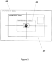
aperture 33 in front of thephotodetector 35 provides a larger or smaller field of view 45 (Figure 5 ), as required by the operator. The aperture size can be adjustable in use, or can be a pre-set aperture size determined during manufacturing and assembly. The photodetector field ofview 45 is smaller (i.e. of the order of microradians) than the standard coarse 44 orfine 47 pointing fields of view of thepointing system 21 which tend to be of the order of degrees or miliradians respectively. - The switching system 13 (
Figure 6 ) in thecontrol system 3 provides an independent control means to prevent accidental firing. The switchingsystem 13 includes aradio frequency emitter 51 configured to emit asignal 52 with a specific frequency and aradio frequency receiver 53. Theradio frequency emitter 51 is located adjacent thecontrol system 3. Theradio frequency receiver 51 is located with theoptical device 2. - The
radio frequency receiver 53 listens for thespecific frequency signal 52. Only when thesignal 52 is received, is a switch (not shown) activated to turn on thelaser diode 2. Thus, even when the pointing and tracking systems are "locked on" to thetarget 5, the high-energy laser 18 is prevented from firing, providing an additional level of security. The switchingsystem 13 provides an independent high integrity turn on/off mechanism for thelaser diode 2, which in turn controls emissions from the high-energy laser 18. - To activate the
switching system 13, theradio frequency emitter 51 can be manually switched on via a push-button switch (not shown) . - In an alternative embodiment of the invention, the switching
system 13 is omitted but instead thephotodetector 35 is switched on or off by an operator. - In the second example embodiment of the invention, the optical device of the
safety assembly 1a is a retro-reflector 2a attached to thetarget 5a instead of a light source (Figure 7 ). A light source in the form of alaser diode 55a is located with theoptical components 11a in the control system. The other components of the safety assembly are similar to the first example embodiment, and like reference numerals denote similar parts. The second example embodiment of the invention does not include a switching system. - The
laser diode 55a is arranged along thepointing system 21a boresight 23a such that thelaser beam 29a passes through the second 31a and first 19a dichroic mirrors respectively, before being reflected by thepointing mirror 25a, out towards thetarget 5a. Thesafety assembly 1a operates in a similar manner to thesafety assembly 1 of the first example embodiment of the invention except that the laserdiode light beam 29a originates within the control system and is reflected from thetarget 5a, before being detected by thephotodetector 35a. The arrangement of the second example embodiment of the invention may provide the benefit of retaining all active components within the control system (attached to the laser-directed energy weapon) for easier access. In the second example embodiment of the invention, the broad light beam is provided through a combination of a wide emitted beam angle from thelaser diode 55a and the reflecting surface of theretroreflector 2a. - The
safety assemblies optical device target target - When the pointing direction cannot be confirmed, or is confirmed and then lost, the high-
energy laser - As stated, the
safety assemblies target laser diode target light beam optical components target - In yet a further advantage over laser-directed energy weapon safety systems of the prior art, the required buffer zones around the permitted firing arc are greatly reduced, since the removal of the PERMIT signal is almost instantaneous (leading to a reduced error margin). Therefore, the firing arcs (made up of the permitted firing arc and buffer zones) can be much smaller than possible using laser-directed energy weapon safety systems of the prior art, and multiple firing arcs can also be simulated.
- Whilst the present invention has been described and illustrated with reference to particular embodiments, it will be appreciated by those of ordinary skill in the art that the invention lends itself to many different variations not specifically illustrated herein. By way of example only, certain possible variations will now be described.
- For example, instead of a frequency modulated reference signal, some other "key" may be used, such as a specific colour of light, or light pattern. The "key" must transmit with high spatial resolution i.e. sound waves are unsuitable due to their divergence.
- Instead of a laser diode, there may be an alternative light source. For example, in certain applications a light-emitting diode may be suitable.
Claims (19)
- A laser-directed energy weapon safety system comprising a laser-directed energy weapon (4) and a safety assembly (1) for use with the laser-directed energy weapon (4), the safety assembly comprising:a control system (3) comprising a photodetector (35) and a processing unit (15); characterized in that the safety assembly further comprisesan optical device (2) configured to attach to a target (5) such that, when attached, the optical device provides a light beam (29) to the photodetector (35);the processing unit (15) being arranged to compare the received light beam against one or more predetermined attributes, and to permit the laser-directed energy weapon (4) to fire only when the received light beam is determined to have the one or more attributes.
- A laser-directed energy weapon safety system according to claim 1, wherein the processing unit (15) is arranged to prevent the laser-directed energy weapon (4) from firing when no light beam (29) is received.
- A laser-directed energy weapon safety system according to claim 1 or 2, wherein the optical device (2) is configured to provide a light beam (29) continuously to the photodetector (35).
- A laser-directed energy weapon safety system according to any of claims 1-3, wherein the optical device (2) comprises a light source.
- A laser-directed energy weapon safety system according to any of claims 1-3, wherein the optical device comprises a retro-reflector (2a), and wherein the control system comprises a light source (55a), and wherein when attached to the target, the optical device (2a) provides a reflected light beam (29a) to the photodetector (35a).
- A laser-directed energy weapon safety system according to any of claims 3-5, wherein the light source is a laser diode (55a) configured to emit a frequency modulated light beam.
- A laser-directed energy weapon safety system according to claim 6, wherein the processing unit (3) is arranged to demodulate the light beam received by the photodetector.
- A laser-directed energy weapon safety system according to claim 6 or 7, wherein the laser diode (55a) is configured to emit light with a modulation frequency in excess of 100Hz.
- A laser-directed energy weapon safety system according to any of claims 6-8, wherein the laser diode (55a) is configured such that in use, the emitted light has a wavelength distinct from the wavelengths of a main laser (18) comprised in the laser-directed energy weapon (4).
- A laser-directed energy weapon safety system according to any preceding claim, wherein the optical device (2) is configured to provide a wide-angle light beam.
- A laser-directed energy weapon safety system according to any preceding claim, wherein the control system comprises one or more dichroic mirrors (19, 31).
- A laser-directed energy weapon safety system according to any preceding claim, wherein the processing unit is arranged to output a signal (16) permitting the laser-directed energy weapon to fire upon determining that the received light beam has the one or more attributes and to not output a signal (16) permitting the laser-directed energy weapon to fire in the absence of such a determination.
- A laser-directed energy weapon safety system according to claim 12, wherein the processing unit is arranged to output a signal (16) preventing the laser-directed energy weapon from firing in the absence of such a determination.
- A laser-directed energy weapon safety system according to any preceding claim, wherein the control system further comprises an aperture (33)arranged with respect to the photodetector (35) to constrict the photodetector field of view.
- A laser-directed energy weapon safety system according to any preceding claim, wherein the safety assembly is configured to attach to a laser-directed energy weapon (4), such that when attached, the photodetector (35) field of view aligns with the laser-directed energy weapon boresight (23.
- A laser-directed energy weapon safety system according to any preceding claim when dependent on claim 4, wherein the safety assembly comprises a radio frequency emitter (51) associated with the control system, and a radio frequency receiver associated with the optical device (53), the radio frequency emitter and receiver being arranged in use to emit and receive respectively a specific frequency signal, wherein in the absence of receipt of the specific frequency signal the light source is disabled.
- A laser-directed energy weapon safety system according to any preceding claim, further comprising the target.
- A method of preventing firing of a laser-directed energy weapon (4), including the steps of:attaching an optical device (2) to a target (5);attaching a photodetector (35) to the laser-directed energy weapon (4);providing a light beam (29) from the optical device to the photodetector;comparing the light beam received by the photodetector against one or more attributes;wherein only upon determining that the light beam has the one or more attributes, permitting the laser-directed energy weapon to fire.
- A method according to claim 18, wherein permitting the laser-directed energy weapon to fire comprises outputting
a signal (16) permitting the laser-directed energy weapon to fire to the high energy laser of the the laser-directed energy weapon.
Applications Claiming Priority (2)
| Application Number | Priority Date | Filing Date | Title |
|---|---|---|---|
| GB2007108.0A GB2595213B (en) | 2020-05-12 | 2020-05-12 | Safety assembly |
| PCT/GB2021/051119 WO2021229208A1 (en) | 2020-05-12 | 2021-05-10 | Safety assembly |
Publications (3)
| Publication Number | Publication Date |
|---|---|
| EP4150287A1 EP4150287A1 (en) | 2023-03-22 |
| EP4150287B1 true EP4150287B1 (en) | 2025-06-25 |
| EP4150287C0 EP4150287C0 (en) | 2025-06-25 |
Family
ID=76269757
Family Applications (1)
| Application Number | Title | Priority Date | Filing Date |
|---|---|---|---|
| EP21729912.2A Active EP4150287B1 (en) | 2020-05-12 | 2021-05-10 | Safety assembly |
Country Status (9)
| Country | Link |
|---|---|
| US (1) | US12292263B2 (en) |
| EP (1) | EP4150287B1 (en) |
| JP (1) | JP7858548B2 (en) |
| AU (1) | AU2021269886A1 (en) |
| CA (1) | CA3182938A1 (en) |
| ES (1) | ES3038145T3 (en) |
| GB (1) | GB2595213B (en) |
| PL (1) | PL4150287T3 (en) |
| WO (1) | WO2021229208A1 (en) |
Family Cites Families (15)
| Publication number | Priority date | Publication date | Assignee | Title |
|---|---|---|---|---|
| DE3405017C2 (en) * | 1984-02-13 | 1994-04-14 | Wegmann & Co Gmbh | Device for monitoring combat vehicles, in particular main battle tanks, during practice shooting with simulated shots |
| JPH0214590U (en) * | 1988-06-30 | 1990-01-30 | ||
| KR100527338B1 (en) * | 2000-10-09 | 2005-11-09 | (주)스탠다드레이저시스템 | Simulated Engagement System and Method Against Tank |
| DE10050691A1 (en) * | 2000-10-13 | 2002-05-02 | Stn Atlas Elektronik Gmbh | Method and device for firing simulation |
| JP3662863B2 (en) | 2001-07-31 | 2005-06-22 | Necパーソナルプロダクツ株式会社 | Light gun, target box, shooting box, and light gun shooting system |
| JP3673256B2 (en) * | 2002-12-13 | 2005-07-20 | 株式会社貴光 | Laser shooting system |
| JP4718832B2 (en) * | 2004-12-28 | 2011-07-06 | 株式会社東芝 | Optical transmission system and optical transmission method |
| IL177080A0 (en) * | 2006-03-15 | 2007-08-19 | Israel Aerospace Ind Ltd | Combat training system and method |
| US9068798B2 (en) * | 2010-07-19 | 2015-06-30 | Cubic Corporation | Integrated multifunction scope for optical combat identification and other uses |
| US10634813B2 (en) * | 2015-05-18 | 2020-04-28 | Lasermotive, Inc. | Multi-layered safety system |
| US11368054B2 (en) * | 2016-02-22 | 2022-06-21 | Lasermotive, Inc. | Remote power safety system |
| WO2018097775A1 (en) * | 2016-11-25 | 2018-05-31 | Saab Ab (Publ) | A simulation device and a method for facilitating simulation of a shot from a weapon |
| US11561294B2 (en) * | 2018-07-27 | 2023-01-24 | Vision Engineering Solutions, LLC | Laser safety system |
| WO2020160055A1 (en) * | 2019-01-28 | 2020-08-06 | Frederick Lee Newton | Methods and apparatus for non-lethal weapons |
| US11567341B2 (en) * | 2019-09-03 | 2023-01-31 | Raytheon Company | System and method for correcting for atmospheric jitter and high energy laser broadband interference using fast steering mirrors |
-
2020
- 2020-05-12 GB GB2007108.0A patent/GB2595213B/en active Active
-
2021
- 2021-05-10 PL PL21729912.2T patent/PL4150287T3/en unknown
- 2021-05-10 JP JP2022568884A patent/JP7858548B2/en active Active
- 2021-05-10 US US17/924,397 patent/US12292263B2/en active Active
- 2021-05-10 ES ES21729912T patent/ES3038145T3/en active Active
- 2021-05-10 CA CA3182938A patent/CA3182938A1/en active Pending
- 2021-05-10 AU AU2021269886A patent/AU2021269886A1/en active Pending
- 2021-05-10 WO PCT/GB2021/051119 patent/WO2021229208A1/en not_active Ceased
- 2021-05-10 EP EP21729912.2A patent/EP4150287B1/en active Active
Also Published As
| Publication number | Publication date |
|---|---|
| NZ794362A (en) | 2025-06-27 |
| WO2021229208A1 (en) | 2021-11-18 |
| PL4150287T3 (en) | 2025-08-11 |
| CA3182938A1 (en) | 2021-11-18 |
| GB2595213A (en) | 2021-11-24 |
| US20230184519A1 (en) | 2023-06-15 |
| AU2021269886A1 (en) | 2022-12-15 |
| JP2023527131A (en) | 2023-06-27 |
| US12292263B2 (en) | 2025-05-06 |
| ES3038145T3 (en) | 2025-10-09 |
| JP7858548B2 (en) | 2026-05-14 |
| EP4150287A1 (en) | 2023-03-22 |
| EP4150287C0 (en) | 2025-06-25 |
| GB2595213B (en) | 2024-02-21 |
Similar Documents
| Publication | Publication Date | Title |
|---|---|---|
| US6549872B2 (en) | Method and apparatus for firing simulation | |
| US8451432B2 (en) | Laser spot tracking with off-axis angle detection | |
| US9170069B1 (en) | Aimpoint offset countermeasures for area protection | |
| US8948591B2 (en) | Method for operating a pulsed interference laser in an eye-safe manner in a DIRCM system | |
| EP0698550B1 (en) | Destruction of underwater objects | |
| DE10195966T1 (en) | Precision gun fire simulation system and method | |
| CN110487120B (en) | Laser defense system and method for remote illumination | |
| KR19990023897A (en) | 2-color activity tracker | |
| US7773202B2 (en) | Laser spot tracker and target identifier | |
| US6072572A (en) | Common aperture multi-sensor boresight mechanism | |
| JP7237604B2 (en) | System and method for jamming target acquisition | |
| US8675186B2 (en) | Systems and methods for targeting directed energy devices | |
| US5664741A (en) | Nutated beamrider guidance using laser designators | |
| US9915504B2 (en) | Gated conjugation laser | |
| US12292263B2 (en) | Safety assembly for training use of a laser-directed energy weapon | |
| USH299H (en) | Covert beam projector | |
| GB2295740A (en) | Eye protection system | |
| CA3191705A1 (en) | Persistant marking of a target | |
| KR102926365B1 (en) | Laser target pointing device using high-speed steering mirror and system including the same | |
| RU2234041C2 (en) | Method for guidance of telecontrolled missile | |
| RU2805094C1 (en) | Aircraft laser protection method | |
| US7781721B1 (en) | Active electro-optic missile warning system |
Legal Events
| Date | Code | Title | Description |
|---|---|---|---|
| STAA | Information on the status of an ep patent application or granted ep patent |
Free format text: STATUS: UNKNOWN |
|
| STAA | Information on the status of an ep patent application or granted ep patent |
Free format text: STATUS: THE INTERNATIONAL PUBLICATION HAS BEEN MADE |
|
| PUAI | Public reference made under article 153(3) epc to a published international application that has entered the european phase |
Free format text: ORIGINAL CODE: 0009012 |
|
| STAA | Information on the status of an ep patent application or granted ep patent |
Free format text: STATUS: REQUEST FOR EXAMINATION WAS MADE |
|
| 17P | Request for examination filed |
Effective date: 20221207 |
|
| AK | Designated contracting states |
Kind code of ref document: A1 Designated state(s): AL AT BE BG CH CY CZ DE DK EE ES FI FR GB GR HR HU IE IS IT LI LT LU LV MC MK MT NL NO PL PT RO RS SE SI SK SM TR |
|
| DAV | Request for validation of the european patent (deleted) | ||
| DAX | Request for extension of the european patent (deleted) | ||
| STAA | Information on the status of an ep patent application or granted ep patent |
Free format text: STATUS: EXAMINATION IS IN PROGRESS |
|
| 17Q | First examination report despatched |
Effective date: 20231108 |
|
| GRAP | Despatch of communication of intention to grant a patent |
Free format text: ORIGINAL CODE: EPIDOSNIGR1 |
|
| STAA | Information on the status of an ep patent application or granted ep patent |
Free format text: STATUS: GRANT OF PATENT IS INTENDED |
|
| INTG | Intention to grant announced |
Effective date: 20250214 |
|
| RBV | Designated contracting states (corrected) |
Designated state(s): AL AT BE BG CH CY CZ DE DK EE ES FI FR GR HR HU IE IS IT LI LT LU LV MC MK MT NL NO PL PT RO RS SE SI SK SM TR |
|
| GRAS | Grant fee paid |
Free format text: ORIGINAL CODE: EPIDOSNIGR3 |
|
| GRAA | (expected) grant |
Free format text: ORIGINAL CODE: 0009210 |
|
| STAA | Information on the status of an ep patent application or granted ep patent |
Free format text: STATUS: THE PATENT HAS BEEN GRANTED |
|
| AK | Designated contracting states |
Kind code of ref document: B1 Designated state(s): AL AT BE BG CH CY CZ DE DK EE ES FI FR GR HR HU IE IS IT LI LT LU LV MC MK MT NL NO PL PT RO RS SE SI SK SM TR |
|
| REG | Reference to a national code |
Ref country code: CH Ref legal event code: EP |
|
| REG | Reference to a national code |
Ref country code: CH Ref legal event code: EP |
|
| REG | Reference to a national code |
Ref country code: IE Ref legal event code: FG4D |
|
| REG | Reference to a national code |
Ref country code: DE Ref legal event code: R096 Ref document number: 602021032865 Country of ref document: DE |
|
| U01 | Request for unitary effect filed |
Effective date: 20250723 |
|
| U07 | Unitary effect registered |
Designated state(s): AT BE BG DE DK EE FI FR IT LT LU LV MT NL PT RO SE SI Effective date: 20250729 |
|
| REG | Reference to a national code |
Ref country code: ES Ref legal event code: FG2A Ref document number: 3038145 Country of ref document: ES Kind code of ref document: T3 Effective date: 20251009 |
|
| PG25 | Lapsed in a contracting state [announced via postgrant information from national office to epo] |
Ref country code: GR Free format text: LAPSE BECAUSE OF FAILURE TO SUBMIT A TRANSLATION OF THE DESCRIPTION OR TO PAY THE FEE WITHIN THE PRESCRIBED TIME-LIMIT Effective date: 20250926 Ref country code: NO Free format text: LAPSE BECAUSE OF FAILURE TO SUBMIT A TRANSLATION OF THE DESCRIPTION OR TO PAY THE FEE WITHIN THE PRESCRIBED TIME-LIMIT Effective date: 20250925 |
|
| PG25 | Lapsed in a contracting state [announced via postgrant information from national office to epo] |
Ref country code: HR Free format text: LAPSE BECAUSE OF FAILURE TO SUBMIT A TRANSLATION OF THE DESCRIPTION OR TO PAY THE FEE WITHIN THE PRESCRIBED TIME-LIMIT Effective date: 20250625 |
|
| PG25 | Lapsed in a contracting state [announced via postgrant information from national office to epo] |
Ref country code: RS Free format text: LAPSE BECAUSE OF FAILURE TO SUBMIT A TRANSLATION OF THE DESCRIPTION OR TO PAY THE FEE WITHIN THE PRESCRIBED TIME-LIMIT Effective date: 20250925 |
|
| PG25 | Lapsed in a contracting state [announced via postgrant information from national office to epo] |
Ref country code: IS Free format text: LAPSE BECAUSE OF FAILURE TO SUBMIT A TRANSLATION OF THE DESCRIPTION OR TO PAY THE FEE WITHIN THE PRESCRIBED TIME-LIMIT Effective date: 20251025 |
|
| PG25 | Lapsed in a contracting state [announced via postgrant information from national office to epo] |
Ref country code: SM Free format text: LAPSE BECAUSE OF FAILURE TO SUBMIT A TRANSLATION OF THE DESCRIPTION OR TO PAY THE FEE WITHIN THE PRESCRIBED TIME-LIMIT Effective date: 20250625 |
|
| PG25 | Lapsed in a contracting state [announced via postgrant information from national office to epo] |
Ref country code: CZ Free format text: LAPSE BECAUSE OF FAILURE TO SUBMIT A TRANSLATION OF THE DESCRIPTION OR TO PAY THE FEE WITHIN THE PRESCRIBED TIME-LIMIT Effective date: 20250625 |
|
| PG25 | Lapsed in a contracting state [announced via postgrant information from national office to epo] |
Ref country code: SK Free format text: LAPSE BECAUSE OF FAILURE TO SUBMIT A TRANSLATION OF THE DESCRIPTION OR TO PAY THE FEE WITHIN THE PRESCRIBED TIME-LIMIT Effective date: 20250625 |
|
| PLBE | No opposition filed within time limit |
Free format text: ORIGINAL CODE: 0009261 |
|
| STAA | Information on the status of an ep patent application or granted ep patent |
Free format text: STATUS: NO OPPOSITION FILED WITHIN TIME LIMIT |
|
| REG | Reference to a national code |
Ref country code: CH Ref legal event code: L10 Free format text: ST27 STATUS EVENT CODE: U-0-0-L10-L00 (AS PROVIDED BY THE NATIONAL OFFICE) Effective date: 20260507 |