EP4149215A1 - Rotating capacitor, circular accelerator, and particle therapy system - Google Patents
Rotating capacitor, circular accelerator, and particle therapy system Download PDFInfo
- Publication number
- EP4149215A1 EP4149215A1 EP22193805.3A EP22193805A EP4149215A1 EP 4149215 A1 EP4149215 A1 EP 4149215A1 EP 22193805 A EP22193805 A EP 22193805A EP 4149215 A1 EP4149215 A1 EP 4149215A1
- Authority
- EP
- European Patent Office
- Prior art keywords
- frequency
- radio
- electrode
- circular accelerator
- rotating capacitor
- Prior art date
- Legal status (The legal status is an assumption and is not a legal conclusion. Google has not performed a legal analysis and makes no representation as to the accuracy of the status listed.)
- Pending
Links
Images


Classifications
-
- H—ELECTRICITY
- H05—ELECTRIC TECHNIQUES NOT OTHERWISE PROVIDED FOR
- H05H—PLASMA TECHNIQUE; PRODUCTION OF ACCELERATED ELECTRICALLY-CHARGED PARTICLES OR OF NEUTRONS; PRODUCTION OR ACCELERATION OF NEUTRAL MOLECULAR OR ATOMIC BEAMS
- H05H7/00—Details of devices of the types covered by groups H05H9/00, H05H11/00, H05H13/00
- H05H7/02—Circuits or systems for supplying or feeding radio-frequency energy
-
- H—ELECTRICITY
- H05—ELECTRIC TECHNIQUES NOT OTHERWISE PROVIDED FOR
- H05H—PLASMA TECHNIQUE; PRODUCTION OF ACCELERATED ELECTRICALLY-CHARGED PARTICLES OR OF NEUTRONS; PRODUCTION OR ACCELERATION OF NEUTRAL MOLECULAR OR ATOMIC BEAMS
- H05H13/00—Magnetic resonance accelerators; Cyclotrons
- H05H13/04—Synchrotrons
-
- A—HUMAN NECESSITIES
- A61—MEDICAL OR VETERINARY SCIENCE; HYGIENE
- A61N—ELECTROTHERAPY; MAGNETOTHERAPY; RADIATION THERAPY; ULTRASOUND THERAPY
- A61N5/00—Radiation therapy
- A61N5/10—X-ray therapy; Gamma-ray therapy; Particle-irradiation therapy
- A61N5/1077—Beam delivery systems
- A61N5/1078—Fixed beam systems
-
- H—ELECTRICITY
- H01—ELECTRIC ELEMENTS
- H01G—CAPACITORS; CAPACITORS, RECTIFIERS, DETECTORS, SWITCHING DEVICES, LIGHT-SENSITIVE OR TEMPERATURE-SENSITIVE DEVICES OF THE ELECTROLYTIC TYPE
- H01G5/00—Capacitors in which the capacitance is varied by mechanical means, e.g. by turning a shaft; Processes of their manufacture
- H01G5/04—Capacitors in which the capacitance is varied by mechanical means, e.g. by turning a shaft; Processes of their manufacture using variation of effective area of electrode
- H01G5/06—Capacitors in which the capacitance is varied by mechanical means, e.g. by turning a shaft; Processes of their manufacture using variation of effective area of electrode due to rotation of flat or substantially flat electrodes
-
- H—ELECTRICITY
- H05—ELECTRIC TECHNIQUES NOT OTHERWISE PROVIDED FOR
- H05H—PLASMA TECHNIQUE; PRODUCTION OF ACCELERATED ELECTRICALLY-CHARGED PARTICLES OR OF NEUTRONS; PRODUCTION OR ACCELERATION OF NEUTRAL MOLECULAR OR ATOMIC BEAMS
- H05H7/00—Details of devices of the types covered by groups H05H9/00, H05H11/00, H05H13/00
- H05H7/10—Arrangements for ejecting particles from orbits
-
- A—HUMAN NECESSITIES
- A61—MEDICAL OR VETERINARY SCIENCE; HYGIENE
- A61N—ELECTROTHERAPY; MAGNETOTHERAPY; RADIATION THERAPY; ULTRASOUND THERAPY
- A61N5/00—Radiation therapy
- A61N5/10—X-ray therapy; Gamma-ray therapy; Particle-irradiation therapy
- A61N2005/1085—X-ray therapy; Gamma-ray therapy; Particle-irradiation therapy characterised by the type of particles applied to the patient
- A61N2005/1087—Ions; Protons
-
- H—ELECTRICITY
- H05—ELECTRIC TECHNIQUES NOT OTHERWISE PROVIDED FOR
- H05H—PLASMA TECHNIQUE; PRODUCTION OF ACCELERATED ELECTRICALLY-CHARGED PARTICLES OR OF NEUTRONS; PRODUCTION OR ACCELERATION OF NEUTRAL MOLECULAR OR ATOMIC BEAMS
- H05H13/00—Magnetic resonance accelerators; Cyclotrons
- H05H13/02—Synchrocyclotrons, i.e. frequency modulated cyclotrons
-
- H—ELECTRICITY
- H05—ELECTRIC TECHNIQUES NOT OTHERWISE PROVIDED FOR
- H05H—PLASMA TECHNIQUE; PRODUCTION OF ACCELERATED ELECTRICALLY-CHARGED PARTICLES OR OF NEUTRONS; PRODUCTION OR ACCELERATION OF NEUTRAL MOLECULAR OR ATOMIC BEAMS
- H05H7/00—Details of devices of the types covered by groups H05H9/00, H05H11/00, H05H13/00
- H05H7/02—Circuits or systems for supplying or feeding radio-frequency energy
- H05H2007/025—Radiofrequency systems
-
- H—ELECTRICITY
- H05—ELECTRIC TECHNIQUES NOT OTHERWISE PROVIDED FOR
- H05H—PLASMA TECHNIQUE; PRODUCTION OF ACCELERATED ELECTRICALLY-CHARGED PARTICLES OR OF NEUTRONS; PRODUCTION OR ACCELERATION OF NEUTRAL MOLECULAR OR ATOMIC BEAMS
- H05H2277/00—Applications of particle accelerators
- H05H2277/10—Medical devices
- H05H2277/11—Radiotherapy
Definitions
- the present invention relates to a rotating capacitor used for a circular accelerator of a particle beam, a circular accelerator, and a particle therapy system using the circular accelerator.
- a synchrocyclotron and an eccentric orbit type accelerator disclosed in JP 2019-133745 A are known as a circular accelerator of a type in which a main magnetic field intensity is set to be temporally constant and a frequency of an acceleration radiofrequency is temporally modulated.
- a circular accelerator of a type in which a main magnetic field intensity is set to be temporally constant and a frequency of an acceleration radiofrequency is temporally modulated.
- it is relatively easy to making the high magnetic field by using the superconducting coil for generating the main magnetic field.
- the circular accelerators are particularly applied to a particle therapy system.
- a rotating capacitor In the synchronous cyclotron or the eccentric orbit type accelerator, a rotating capacitor is used as an element that modulates a frequency of a radio frequency for accelerating a charged particle beam.
- the rotating capacitor generally includes a stator electrode, a rotor electrode disposed to face the stator electrode, a rotation shaft that rotates the rotor electrode, and a bearing that supports the rotation shaft.
- JP 2020-095772 A discloses an example of such a rotating capacitor.
- the bearing of the rotating capacitor needs to withstand high-speed rotation of the rotation shaft.
- a radio-frequency current may flow through the bearing along the wall surface of a housing. Therefore, the bearing is a consumable item, and it is necessary to periodically replace the bearing.
- the stator electrode, the rotor electrode, the rotation shaft, and the bearing are disposed in a vacuumed housing.
- the bearing is disposed in the vacuumed housing, it is necessary to open the housing to the atmosphere every time the bearing is replaced. In addition, it is necessary to perform the work of opening the housing to the atmosphere, replacing the bearing, and then vacuuming the inside of the housing again. Thus, workability of maintenance of the bearing is deteriorated.
- An object of the present invention is to improve workability of maintenance of a bearing of a rotating capacitor used in a circular accelerator.
- a rotating capacitor used in a circular accelerator that accelerates a charged particle beam by feeding a first radio frequency to a DC main magnetic field, the rotating capacitor modulating a frequency of the first radio frequency.
- the rotating capacitor includes a stator electrode, a rotor electrode that is disposed to face the stator electrode and is used for modulating the frequency of the first radio frequency together with the stator electrode, a vacuum seal that performs vacuum sealing around a rotation shaft for rotating the rotor electrode, and a bearing that is installed on an atmosphere side and supports the rotation shaft.
- a circular accelerator including the rotating capacitor.
- the charged particle beam is accelerated by feeding the first radio frequency to the DC main magnetic field.
- a particle therapy system including the circular accelerator, and an irradiation device that irradiates a patient with a charged particle beam extracted from the circular accelerator.
- a rotating capacitor according to the present invention is suitable for a circular accelerator, but is not limited to the application thereof.
- the circular accelerator according to the present invention is suitable for a particle therapy system, but is not limited to the application thereof.
- FIG. 1 is a perspective view illustrating an appearance of a circular accelerator 39 according to the present embodiment.
- Fig. 2 is a cross-sectional view illustrating a lateral cross section (center plane) of the circular accelerator 39.
- Fig. 3 is a cross-sectional view taken along line A-A in Fig. 2 , and is a cross-sectional view illustrating a longitudinal cross section of the circular accelerator 39.
- the circular accelerator 39 is a device that accelerates a beam by a frequency-modulated radio-frequency electric field in a main magnetic field having temporally constant intensity.
- a circular accelerator that accelerates a proton beam to 235 MeV will be described, but the circular accelerator 39 may be a device that accelerates a heavy particle beam of helium, carbon, or the like.
- the circular accelerator 39 is an eccentric orbit type accelerator in which a main magnetic field is formed to cause a beam orbit to be eccentric toward a beam extraction path inlet 82.
- the circular accelerator 39 can extract a beam by freely changing the beam energy between 70 MeV and 235 MeV.
- the outer shell of the circular accelerator 39 is formed by a main electromagnet 40 that can be divided in an up-down direction.
- An acceleration region is formed on the center plane in the main electromagnet 40, and the acceleration region is vacuumed.
- An orbit through which a beam passes until the energy of the beam reaches 235 MeV of the maximum energy after the beam starts to be accelerated in the acceleration region is referred to as a closed orbit below.
- an orbit through which a beam having energy of 235 MeV being the maximum energy passes is referred to as a maximum energy orbit 80 (see Fig. 2 ).
- An orbit through which a beam having an energy of 70 MeV passes is referred to as a minimum extraction energy orbit.
- a plane on which the closed orbit draws a spiral is referred to as an orbital plane.
- the main electromagnet 40 includes a main magnetic pole 38, a yoke 41, and a main coil 42.
- the appearance of the main electromagnet 40 is formed by the yoke 41.
- a substantially cylindrical region is formed in the yoke 41.
- the main coil 42 is an annular superconducting coil and is installed along the inner wall of the yoke 41.
- a cryostat 60 is installed around the main coil 42, and the main coil 42 is cooled by the cryostat 60.
- the main magnetic poles 38 are installed on the inner peripheral side of the main coil 42 to vertically face each other.
- the main magnetic field is used for forming an eccentric orbit.
- the acceleration region is a region for accelerating a beam in the main magnetic field.
- a plurality of through-holes are formed in the yoke 41.
- a beam through-hole 46, a coil through-hole 48, a vacuuming through-hole 49, and a through-hole for RF accelerating system 50 are formed.
- the beam through-hole 46 is a through-hole for extracting an accelerated beam.
- the coil through-hole 48 is a through-hole for drawing out various coil conductors installed in the yoke 41.
- the vacuuming through-hole 49 is a through-hole for vacuuming the acceleration region.
- the through-hole for RF accelerating system 50 is a through-hole for an accelerating cavity 10, and is provided on a connection surface between upper and lower magnetic poles.
- an ion source 53 is installed over the main electromagnet 40.
- the ion source 53 generates a beam of ions injected to the main electromagnet 40.
- the beam generated by the ion source 53 passes through a low energy beam transport 54 and is injected to the acceleration region in the main electromagnet 40 via an ion injection portion 52.
- an ECR ion source or the like can be applied as the ion source 53.
- the ion source 53 may be disposed inside the vacuumed acceleration region in the main electromagnet 40. In this case, a PIG type ion source or the like is suitable.
- the ion injection portion 52 is disposed closer to the beam extraction path inlet 82 side than the mechanical center of the acceleration region on the center line.
- a beam of charged particles generated by the ion source 53 passes through the low energy beam transport 54 and is injected to the acceleration region in the main electromagnet 40 by an inflector electrode (not illustrated) or the like via the ion injection portion 52.
- the injected beam is accelerated by a radio-frequency electric field and circulates in the main magnetic field while increasing energy. As the beam is accelerated, the radius of curvature of the orbit increases, and the beam draws a spiral orbit from the center toward the outside of the acceleration region.
- the radio frequency for accelerating the beam corresponds to an example of a first radio frequency.
- the accelerating cavity 10 is a ⁇ /2 resonance type cavity and includes a dee electrode 12, a dummy dee electrode 13, an inner conductor 14, an outer conductor 15, and a rotating capacitor 22.
- the dee electrode 12 is a hollow electrode through which a beam passes, and is joined to the inner conductor 14.
- the dummy dee electrode 13 is an electrode having a ground potential and is joined to the outer conductor 15 wrapping the inner conductor 14.
- An acceleration gap 11 is formed between the dee electrode 12 and the dummy dee electrode 13. A radio-frequency electric field is formed in the acceleration gap 11.
- the radiofrequency power is supplied to the accelerating cavity 10 by a radiofrequency power supply 21 via an input coupler 20.
- the input coupler 20 is coupled with the accelerating cavity 10 by either electrostatic coupling or magnetic coupling.
- a radio-frequency acceleration voltage for accelerating a beam and a radio-frequency electric field by the radio-frequency acceleration voltage are generated in the acceleration gap 11.
- the rotating capacitor 22 is a device for modulating the resonance frequency of the accelerating cavity 10.
- the resonance frequency of the accelerating cavity 10 is changed by temporally changing the capacitance of the rotating capacitor 22, and thereby a frequency modulation pattern can be formed.
- An acceleration voltage frequency-modulated by the rotating capacitor 22 is generated in the acceleration gap 11 between the dee electrode 12 and the dummy dee electrode 13.
- the acceleration gap 11 illustrated in Fig. 2 is an acceleration gap having a harmonic number of 1, that is, an acceleration gap in which the circulating frequency and the acceleration frequency are equal to each other. Such an acceleration gap is formed in accordance with a beam orbit shape.
- the radiofrequency power supply 21 supplies radiofrequency power having a frequency that follows a change in the resonance frequency of the accelerating cavity 10, by either a self-excited method or an other-excited system.
- the main magnetic field that realizes the eccentric orbit will be described below.
- the main magnetic field may be a magnetic field of a type in which the main magnetic field intensity is constant in a circumferential direction, or may be an azimuthal varying field (AVF) type magnetic field.
- the main magnetic field distribution is a non-isochronous magnetic field.
- ⁇ is the deflection radius of a design orbit
- B is the magnetic field intensity
- ⁇ B/ ⁇ r is the magnetic field gradient in a radial direction.
- the betatron frequency (tune in a horizontal direction) ⁇ r in a direction that is parallel to the orbital plane and perpendicular to the orbit is set to a value close to 1.
- the main magnetic field distribution described above is formed by the main magnetic pole 38 and a trim coil and a magnetic pole piece (both not illustrated) installed on the surface of the main magnetic pole 38.
- the above components are arranged vertically symmetrically with respect to the orbital plane.
- the main magnetic field has only a magnetic field component in a direction perpendicular to the orbital plane, on the orbital plane.
- Fig. 4 illustrates a closed orbit of each energy. Orbits of 50 kinds of energies are indicated by solid lines for every 0.04 Tm of the magnetic rigidity modulus from the maximum energy of 235 MeV. A dotted line is a line connecting the same circulating phase in each orbit, and is referred to as an equal circulating phase line. The equal circulating phase line is plotted for each circulating phase n/20 from an aggregation region.
- the acceleration gap 11 formed between the dee electrode 12 and the dummy dee electrode 13 is installed along the equal circulating phase line. More specifically, the dee electrode 12 has a hollow shape such as a fan shape with a tip near the center of the concentric orbit and a radius along the equal circulating phase line.
- An orbit in a region where the energy of the beam is low is close to the concentric orbit centered on the vicinity of the ion injection portion 52, similarly to the conventional cyclotron.
- the orbits having larger energy are densely gathered on the beam extraction path inlet 82 side.
- the orbits of the respective energies are in a positional relationship of being spaced from each other on the inner conductor 14 side.
- a point where the obits are densely gathered is referred to as an aggregation region, and a region where the orbits are discrete is referred to as a discrete region.
- Fig. 5A is a graph illustrating a relationship among the resonance frequency f cav of the accelerating cavity 10, a frequency f ext , and the time point T.
- the frequency f ext is the frequency of the radio-frequency electric field fed to the beam by the radio-frequency kicker 70.
- Fig. 5B is a graph illustrating a relationship among the acceleration voltage V acc generated in the acceleration gap 11, the radio-frequency voltage V ext fed to the radio-frequency kicker 70, and the time point T.
- Fig. 5C is a graph illustrating a relationship between the current of the injected beam and the current of the extracted beam, and the time point T.
- the radio frequency fed to the radio-frequency kicker 70 corresponds to an example of a second radio frequency.
- One acceleration cycle starts from the rising edge of the acceleration voltage V acc (time point T1). Then, when the acceleration voltage V acc sufficiently rises, a beam is injected to the circular accelerator 39 from the ion source 53 (time point T2). After a lapse of the time t 1 from the injection of the beam to the circular accelerator 39, the radio frequency capturing of the beam ends.
- the captured beam that is, the beam ready for acceleration among the injected beams starts to be accelerated by the acceleration voltage V acc (time point T3).
- the blocking of the acceleration radio frequency is started (time point T4).
- the acceleration voltage V acc is turned off (time point T5), and the beam circulates around a certain orbit.
- the individual charged particles forming the beam oscillates in a direction perpendicular to the orbit of the beam at the time of circulating.
- This oscillation is referred to as betatron oscillation, and the frequency of this oscillation is referred to as a betatron frequency.
- the frequency per round is referred to as a tune, and the displacement on the r-axis of the beam to the outside of the orbit plane per round is referred to as turn separation.
- the betatron oscillation in a direction orthogonal to the orbit of the beam in the orbital plane is referred to as a horizontal betatron oscillation, and the tune is referred to as a horizontal tune.
- This betatron oscillation has a property that resonance occurs and the amplitude rapidly increases when an appropriate radio-frequency voltage is fed.
- the feeding of the radio-frequency voltage V ext to the radio-frequency kicker 70 is started.
- the start of the feeding of the radio-frequency voltage V ext to the radio-frequency kicker 70 (time point T5) does not have to be exactly the same as when the acceleration voltage V acc is turned OFF.
- the feeding of the radio-frequency voltage V ext may be started immediately before, simultaneously with, or immediately after the start of blocking of the acceleration radio frequency (time point T4), or may be started immediately before or immediately after the acceleration voltage V acc is in the OFF state.
- the energy desired to be taken out can be controlled by the feeding time of the acceleration voltage V acc .
- the radio-frequency voltage of the radio-frequency kicker 70 quickly rises with a response of several ⁇ s if the radio-frequency kicker 70 does not have a resonator structure and is designed so that the capacitance has an appropriate value.
- the betatron oscillation have the property that the amplitude increases resonantly when the product of either the horizontal tune or the fractional part of the horizontal tune and the circulating frequency of the beam is substantially equal to the frequency of the fed radio-frequency voltage.
- the frequency f ext of the radio-frequency voltage is determined to be substantially same as the product ⁇ r ⁇ f rev of the fractional part ⁇ r of the horizontal tune ⁇ r of the maximum energy beam and the circulating frequency f rev of the beam having energy desired to be taken out.
- a radio-frequency voltage of a finite frequency bandwidth including a frequency component that is substantially the same as the product ⁇ r ⁇ f rev may be fed.
- the amplitude of the horizontal betatron oscillation continues to increase resonantly, and the beam eventually reaches a peeler magnetic field region 44 and a regenerator magnetic field region 45 installed on the outer peripheral side of the maximum energy orbit 80 (time point T6).
- the beam that has reached the peeler magnetic field region 44 is kicked to the outer peripheral side of the orbit plane.
- the beam that has reached the regenerator magnetic field region 45 is kicked to the inner peripheral side of the orbit plane.
- Kicking refers to deflecting a beam by feeding an electric field or a magnetic field.
- the quadrupole magnetic field component of the peeler magnetic field region 44 kicks the beam further to the outer peripheral side, and the turn separation increases.
- the magnetic field of the regenerator magnetic field region 45 suppresses an occurrence of a situation in which the horizontal tune of the beam changes abruptly and prevents an occurrence of a situation in which the betatron oscillation diverges in a vertical direction perpendicular to a horizontal direction by 90 degrees before the beam is extracted, thereby preventing the beam from being lost.
- a septum coil 43 is installed at the beam extraction path inlet 82.
- the turn separation greatly exceeding the thickness of a coil conductor (not illustrated) installed on the inner peripheral side of the septum coil 43 is obtained, the beam is guided into the septum coil 43.
- the beam is sufficiently deflected, is guided to high energy beam transport 47, and then is extracted.
- a radio-frequency voltage as large as possible is fed to quickly increase the amplitude of the beam.
- the radio-frequency voltage is decreased immediately before the beam reaches the peeler magnetic field region 44 or the regenerator magnetic field region 45 (time point T6), and the amount of the beam traveling to the peeler magnetic field region 44 and the regenerator magnetic field region 45 is adjusted. In this manner, it is possible to finely control a beam extraction current.
- the extraction of the beam is stopped (time point T7) by stopping the feeding of the radio-frequency voltage V ext to the radio-frequency kicker 70 after the time t 4 has elapsed from the start of the extraction of the beam (time point T6). It is possible to control the extraction time of the beam by adjusting the time t 4 .
- the beam extraction current can be controlled by controlling the radio-frequency voltage fed to the radio-frequency kicker 70.
- the beam extraction can be resumed by feeding the radio-frequency voltage V ext again (time point T8).
- V ext the radio-frequency voltage
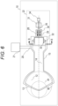
- the rotating capacitor 22 will be described below in detail with reference to Fig. 6 .
- the rotating capacitor 22 is installed at an end portion of the accelerating cavity 10 opposite to the dee electrode 12.
- the rotating capacitor 22 includes a motor 31, a stator electrode 32, a rotor electrode 33, a shaft 35 connecting the rotor electrode and the motor 31, a rotary joint 34, a vacuum seal 29, a bearing 30 of the shaft 35, and a holder 28.
- the stator electrode 32 is formed on the inner conductor 14.
- the rotor electrode 33 is adjacent to the outer conductor 15 and is not physically connected to the outer conductor 15, but is electrically connected to the outer conductor 15 via electrostatic capacitance. Contrary to this configuration, the stator electrode 32 may be formed (physically connected) on the outer conductor 15, and the rotor electrode 33 may be electrostatically coupled to the inner conductor 14.
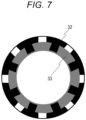
- Fig. 7 is a cross-sectional view taken along line B-B in Fig. 6 .
- the stator electrode 32 and the rotor electrode 33 have a periodically symmetric structure having a notched portion of a certain shape in the circumferential direction, in order to realize a frequency modulation pattern illustrated in Fig. 5A .
- the capacitance formed between the stator electrode 32 and the rotor electrode 33 changes with time.
- the periodically symmetric structure is a structure that is symmetrical eight times.
- the frequency modulation pattern is repeated for eight cycles every time the motor 31 makes one rotation. If the number of times of periodical symmetry is further increased, it is possible to reduce the motor rotation speed, and it is possible to increase the lifespans of the vacuum seal and the bearing.
- the shaft 35 is installed to penetrate the center of the motor 31.
- the rotary joint 34 is installed at an end portion of the shaft 35, and cooling water is supplied into the shaft 35.
- the cooling water is used for cooling the rotor electrode 33.
- the motor 31 illustrated in Fig. 6 is merely an example.
- the motor used in the rotating capacitor 22 may have a structure other than the structure sharing the shaft and the rotation axis. For example, a motor may be installed beside the shaft, and the shaft may be driven via a gear, a pulley, or the like.
- the holder 28 is water-cooled to hold and cool the vacuum seal 29 and the bearing 30.
- the vacuum seal 29 is installed on the dee electrode 12 side, and vacuum-seals the periphery of the shaft 35.
- the bearing 30 that supports the shaft 35 is installed on the opposite side of the dee electrode 12. That is, the bearing 30 is installed on the atmosphere side. Since the bearing 30, which is a consumable, is installed on the atmosphere side, maintenance work such as replacement of the bearing 30 is facilitated. In addition, since it is not necessary to open the vacuum for the maintenance work, it is possible to reduce the down time of the circular accelerator 39. Even though the grease used in the bearing 30 generates dust, the place is in the atmosphere and does not cause deterioration of the degree of vacuum. Thus, problems such as discharge and beam loss do not occur.
- a lip seal, a double O-ring, a Wilson seal, a bellows seal, or the like is used as the vacuum seal 29, a lip seal, a double O-ring, a Wilson seal, a bellows seal, or the like.
- a magnetic fluid seal can be used. This increases the slidability, so that it is possible to expect the increase of the seal lifespan.
- the stator electrode 32, the rotor electrode 33, the inner conductor 14, the outer conductor 15, and the shaft 35, which can be paths through which a radio-frequency current flows, are all members made of conductors.
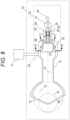
- Fig. 8 illustrates a rotating capacitor according to a first modification example.
- the bypass capacitor 23 may be installed on the vacuum side of the vacuum seal 29 as illustrated in Fig. 8 .
- the bypass capacitor 23 includes a holder-side electrode 24 and a shaft-side electrode 25 facing each other.
- the holder-side electrode 24 is an electrode fixed to a holder 28' that is made of a conductor and is connected to the outer conductor 15.
- the shaft-side electrode 25 is an electrode fixed on the shaft 35.
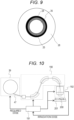
- Fig. 9 illustrates the configuration of the bypass capacitor 23.
- Fig. 9 is a cross-sectional view taken along line C-C in Fig. 8 .
- the holder-side electrode 24 and the shaft-side electrode 25 are electrodes having no notched portion in the circumferential direction. With this configuration, the capacitance increases, and the impedance with respect to the radio frequency decreases. Therefore, the radio-frequency current easily flows through the bypass capacitor 23, and the radio-frequency current flowing through the vacuum seal 29 and the bearing 30 is reduced, so that it is possible to improve the lifespans of the vacuum seal 29 and the bearing 30 and reduce the frequency of the maintenance work.
- the holder-side electrode 24 and the shaft-side electrode 25 may have notched portions in the circumferential direction. When there is the notched portion, the capacitance decreases, but a capacitance change contributing to resonance frequency modulation can be caused similar to the stator electrode and the rotor electrode.
- the holder-side electrode 24 and the shaft-side electrode 25 are configured to have the same wobbling radius as those of the stator electrode and the rotor electrode, and it is possible to enhance the bypass effect of the radio-frequency current by increasing the capacitance.
- the shaft 35 needs to be made of a magnetic material in order to form a magnetic path. If the holder 28 is also made of a magnetic material, it is possible to block a leakage magnetic field leaking from the main electromagnet 40.
- a magnetic fluid shield that covers a region from the outer peripheral side of the outer conductor 15 to the outer peripheral side of the holder 28 may be installed, and a magnetic shield structure that blocks a leakage magnetic field including not only the magnetic fluid shield and the bearing 30 but also the rotor electrode 33 may be adopted.
- a magnetic shield structure that blocks a leakage magnetic field including not only the magnetic fluid shield and the bearing 30 but also the rotor electrode 33 may be adopted.
- the entire rotating capacitor 22 is covered with a housing that is made of a conductor and is connected to the outer conductor 15 without any gap, it is possible to suppress radio-frequency noise that may
- Fig. 10 illustrates the configuration of the particle therapy system.
- the particle therapy system according to the present embodiment includes the circular accelerator 39, a rotating gantry 190, an irradiation device 192 including a scanning coil, a therapy stand 201, and a control apparatus 191 that controls the above components.
- the beam extracted from the circular accelerator 39 is transported to the irradiation device 192 by the rotating gantry 190.
- the transported ion beam is shaped to match with the target shape by the irradiation device 192 and the adjustment of the beam energy, and the target of the patient 200 lying on the therapy stand 201 is irradiated by a predetermined amount.
- the irradiation device 192 includes a dose monitor and monitors the dose with which the patient 200 is irradiated for each irradiation spot.
- the control apparatus 191 calculates a required dose to each irradiation spot based on the dose data, and outputs the calculation result to an arithmetic operation device.
- the bearing 30, which is a consumable item, is installed on the atmosphere side.
- the maintenance work of the bearing 30 for example, replacement of the bearing 30
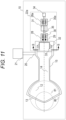
- FIG. 11 is a cross-sectional view illustrating the rotating capacitor according to the second modification example.
- a rotating capacitor 22a according to the second modification example further includes a bearing 30a and a holder 28a in addition to the configuration of the rotating capacitor 22 illustrated in Fig. 6 .
- the bearing 30 corresponds to an example of a first individual bearing
- the bearing 30a corresponds to an example of a second individual bearing.
- the shaft 35 is supported by the bearings 30 and 30a.
- the holder 28a holds the bearing 30a.
- the bearings 30 and 30a are installed at positions spaced from each other on the shaft 35.
- the shaft 35 When the bearing is installed on the atmosphere side, the shaft 35 is longer than when the bearing is installed on the vacuum side, but the shaft 35 can be stably supported by installing the bearings 30 and 30a at the positions spaced from each other.
- Three or more bearings may be installed, and the shaft 35 may be supported by the three or more bearings.
Landscapes
- Engineering & Computer Science (AREA)
- Health & Medical Sciences (AREA)
- Physics & Mathematics (AREA)
- Plasma & Fusion (AREA)
- Spectroscopy & Molecular Physics (AREA)
- Biomedical Technology (AREA)
- Power Engineering (AREA)
- Radiology & Medical Imaging (AREA)
- Nuclear Medicine, Radiotherapy & Molecular Imaging (AREA)
- Life Sciences & Earth Sciences (AREA)
- Animal Behavior & Ethology (AREA)
- General Health & Medical Sciences (AREA)
- Public Health (AREA)
- Veterinary Medicine (AREA)
- Pathology (AREA)
- Microelectronics & Electronic Packaging (AREA)
- Particle Accelerators (AREA)
- Radiation-Therapy Devices (AREA)
Abstract
Description
- The present invention relates to a rotating capacitor used for a circular accelerator of a particle beam, a circular accelerator, and a particle therapy system using the circular accelerator.
- A synchrocyclotron and an eccentric orbit type accelerator disclosed in
JP 2019-133745 A - In the synchronous cyclotron or the eccentric orbit type accelerator, a rotating capacitor is used as an element that modulates a frequency of a radio frequency for accelerating a charged particle beam. The rotating capacitor generally includes a stator electrode, a rotor electrode disposed to face the stator electrode, a rotation shaft that rotates the rotor electrode, and a bearing that supports the rotation shaft.
JP 2020-095772 A - The bearing of the rotating capacitor needs to withstand high-speed rotation of the rotation shaft. In addition, a radio-frequency current may flow through the bearing along the wall surface of a housing. Therefore, the bearing is a consumable item, and it is necessary to periodically replace the bearing.
- In the rotating capacitor according to the conventional technique, the stator electrode, the rotor electrode, the rotation shaft, and the bearing are disposed in a vacuumed housing. When the bearing is disposed in the vacuumed housing, it is necessary to open the housing to the atmosphere every time the bearing is replaced. In addition, it is necessary to perform the work of opening the housing to the atmosphere, replacing the bearing, and then vacuuming the inside of the housing again. Thus, workability of maintenance of the bearing is deteriorated.
- An object of the present invention is to improve workability of maintenance of a bearing of a rotating capacitor used in a circular accelerator.
- According to an aspect of the present invention, there is provided a rotating capacitor used in a circular accelerator that accelerates a charged particle beam by feeding a first radio frequency to a DC main magnetic field, the rotating capacitor modulating a frequency of the first radio frequency. The rotating capacitor includes a stator electrode, a rotor electrode that is disposed to face the stator electrode and is used for modulating the frequency of the first radio frequency together with the stator electrode, a vacuum seal that performs vacuum sealing around a rotation shaft for rotating the rotor electrode, and a bearing that is installed on an atmosphere side and supports the rotation shaft.
- According to another aspect of the present invention, there is provided a circular accelerator including the rotating capacitor. The charged particle beam is accelerated by feeding the first radio frequency to the DC main magnetic field.
- According to still another aspect of the present invention, there is provided a particle therapy system including the circular accelerator, and an irradiation device that irradiates a patient with a charged particle beam extracted from the circular accelerator.
- According to the present invention, it is possible to improve workability of maintenance of a bearing of a rotating capacitor used in a circular accelerator.
-
-
Fig. 1 is a perspective view illustrating an appearance of a circular accelerator according to the present embodiment; -
Fig. 2 is a cross-sectional view illustrating the circular accelerator according to the present embodiment; -
Fig. 3 is a cross-sectional view taken along line A-A inFig. 2 ; -
Fig. 4 is a diagram illustrating beam activation for each energy; -
Figs. 5A to 5C are diagrams illustrating a motion pattern of the circular accelerator according to the present embodiment; -
Fig. 6 is a cross-sectional view illustrating an accelerating cavity and a rotating capacitor according to the present embodiment; -
Fig. 7 is a cross-sectional view taken along line B-B inFig. 6 ; -
Fig. 8 is a cross-sectional view illustrating a rotating capacitor according to a first modification example; -
Fig. 9 is a cross-sectional view taken along line C-C inFig. 8 ; -
Fig. 10 is a diagram illustrating a configuration of a particle therapy system; and -
Fig. 11 is a cross-sectional view illustrating a rotating capacitor according to a second modification example. - Hereinafter, an embodiment of the present invention will be described. The following embodiment is merely an example, and the present invention is not limited to the following specific aspects. The present invention itself can be modified into various forms other than the following embodiment.
- Further, a rotating capacitor according to the present invention is suitable for a circular accelerator, but is not limited to the application thereof. The circular accelerator according to the present invention is suitable for a particle therapy system, but is not limited to the application thereof.
- A configuration of the circular accelerator according to the present embodiment will be described with reference to
Figs. 1 to 3 .Fig. 1 is a perspective view illustrating an appearance of acircular accelerator 39 according to the present embodiment.Fig. 2 is a cross-sectional view illustrating a lateral cross section (center plane) of thecircular accelerator 39.Fig. 3 is a cross-sectional view taken along line A-A inFig. 2 , and is a cross-sectional view illustrating a longitudinal cross section of thecircular accelerator 39. - The
circular accelerator 39 is a device that accelerates a beam by a frequency-modulated radio-frequency electric field in a main magnetic field having temporally constant intensity. As an example, a circular accelerator that accelerates a proton beam to 235 MeV will be described, but thecircular accelerator 39 may be a device that accelerates a heavy particle beam of helium, carbon, or the like. - The
circular accelerator 39 is an eccentric orbit type accelerator in which a main magnetic field is formed to cause a beam orbit to be eccentric toward a beamextraction path inlet 82. Thecircular accelerator 39 can extract a beam by freely changing the beam energy between 70 MeV and 235 MeV. - As illustrated in
Figs. 1 and3 , the outer shell of thecircular accelerator 39 is formed by amain electromagnet 40 that can be divided in an up-down direction. An acceleration region is formed on the center plane in themain electromagnet 40, and the acceleration region is vacuumed. An orbit through which a beam passes until the energy of the beam reaches 235 MeV of the maximum energy after the beam starts to be accelerated in the acceleration region is referred to as a closed orbit below. Among the closed orbits, an orbit through which a beam having energy of 235 MeV being the maximum energy passes is referred to as a maximum energy orbit 80 (seeFig. 2 ). An orbit through which a beam having an energy of 70 MeV passes is referred to as a minimum extraction energy orbit. A plane on which the closed orbit draws a spiral is referred to as an orbital plane. A two-dimensional polar coordinate system of the orbital plane, in which the center of the acceleration region is set as an origin, is determined, and an axis in a radially outer direction from the center is referred to as an r-axis. - As illustrated in
Fig. 3 , themain electromagnet 40 includes a mainmagnetic pole 38, ayoke 41, and amain coil 42. The appearance of themain electromagnet 40 is formed by theyoke 41. A substantially cylindrical region is formed in theyoke 41. Themain coil 42 is an annular superconducting coil and is installed along the inner wall of theyoke 41. Acryostat 60 is installed around themain coil 42, and themain coil 42 is cooled by thecryostat 60. The mainmagnetic poles 38 are installed on the inner peripheral side of themain coil 42 to vertically face each other. A magnetic field in the up-down direction, which is excited by causing a current to flow in themain coil 42 and is formed by the mainmagnetic pole 38, is referred to as the main magnetic field. The main magnetic field is used for forming an eccentric orbit. The acceleration region is a region for accelerating a beam in the main magnetic field. - As illustrated in
Fig. 2 , a plurality of through-holes are formed in theyoke 41. Specifically, a beam through-hole 46, a coil through-hole 48, a vacuuming through-hole 49, and a through-hole forRF accelerating system 50 are formed. The beam through-hole 46 is a through-hole for extracting an accelerated beam. The coil through-hole 48 is a through-hole for drawing out various coil conductors installed in theyoke 41. The vacuuming through-hole 49 is a through-hole for vacuuming the acceleration region. The through-hole forRF accelerating system 50 is a through-hole for an acceleratingcavity 10, and is provided on a connection surface between upper and lower magnetic poles. - As illustrated in
Fig. 1 , anion source 53 is installed over themain electromagnet 40. Theion source 53 generates a beam of ions injected to themain electromagnet 40. The beam generated by theion source 53 passes through a lowenergy beam transport 54 and is injected to the acceleration region in themain electromagnet 40 via anion injection portion 52. As theion source 53, an ECR ion source or the like can be applied. Theion source 53 may be disposed inside the vacuumed acceleration region in themain electromagnet 40. In this case, a PIG type ion source or the like is suitable. - As illustrated in
Fig. 2 , theion injection portion 52 is disposed closer to the beamextraction path inlet 82 side than the mechanical center of the acceleration region on the center line. A beam of charged particles generated by theion source 53 passes through the lowenergy beam transport 54 and is injected to the acceleration region in themain electromagnet 40 by an inflector electrode (not illustrated) or the like via theion injection portion 52. The injected beam is accelerated by a radio-frequency electric field and circulates in the main magnetic field while increasing energy. As the beam is accelerated, the radius of curvature of the orbit increases, and the beam draws a spiral orbit from the center toward the outside of the acceleration region. The radio frequency for accelerating the beam corresponds to an example of a first radio frequency. - The accelerating
cavity 10 is a λ/2 resonance type cavity and includes adee electrode 12, adummy dee electrode 13, aninner conductor 14, anouter conductor 15, and a rotatingcapacitor 22. Thedee electrode 12 is a hollow electrode through which a beam passes, and is joined to theinner conductor 14. Thedummy dee electrode 13 is an electrode having a ground potential and is joined to theouter conductor 15 wrapping theinner conductor 14. Anacceleration gap 11 is formed between thedee electrode 12 and thedummy dee electrode 13. A radio-frequency electric field is formed in theacceleration gap 11. - The radiofrequency power is supplied to the accelerating
cavity 10 by aradiofrequency power supply 21 via aninput coupler 20. Theinput coupler 20 is coupled with the acceleratingcavity 10 by either electrostatic coupling or magnetic coupling. Thus, a radio-frequency acceleration voltage for accelerating a beam and a radio-frequency electric field by the radio-frequency acceleration voltage are generated in theacceleration gap 11. - The rotating
capacitor 22 is a device for modulating the resonance frequency of the acceleratingcavity 10. The resonance frequency of the acceleratingcavity 10 is changed by temporally changing the capacitance of the rotatingcapacitor 22, and thereby a frequency modulation pattern can be formed. An acceleration voltage frequency-modulated by the rotatingcapacitor 22 is generated in theacceleration gap 11 between thedee electrode 12 and thedummy dee electrode 13. Theacceleration gap 11 illustrated inFig. 2 is an acceleration gap having a harmonic number of 1, that is, an acceleration gap in which the circulating frequency and the acceleration frequency are equal to each other. Such an acceleration gap is formed in accordance with a beam orbit shape. - The
radiofrequency power supply 21 supplies radiofrequency power having a frequency that follows a change in the resonance frequency of the acceleratingcavity 10, by either a self-excited method or an other-excited system. - The main magnetic field that realizes the eccentric orbit will be described below. The main magnetic field may be a magnetic field of a type in which the main magnetic field intensity is constant in a circumferential direction, or may be an azimuthal varying field (AVF) type magnetic field. For any type of magnetic field, the main magnetic field distribution is a non-isochronous magnetic field. The main magnetic field distribution is determined to satisfy a beam stabilization condition that the n value represented by the following Formula (1) is more than 0 and less than 1.
[Math. 1]
- Here, ρ is the deflection radius of a design orbit, B is the magnetic field intensity, and ∂B/∂r is the magnetic field gradient in a radial direction. Under the above-described beam stabilization condition, a beam slightly deviated in the radial direction from the design orbit receives a restoring force to return to the design orbit, and a beam deviated in a direction perpendicular to the orbital plane receives a restoring force from the main magnetic field in a direction of returning to the orbital plane. That is, the beam performs betatron oscillation in the vicinity of the design orbit, stably circulates, and is accelerated. In the beam of all energies, the betatron frequency (tune in a horizontal direction) νr in a direction that is parallel to the orbital plane and perpendicular to the orbit is set to a value close to 1. The main magnetic field distribution described above is formed by the main
magnetic pole 38 and a trim coil and a magnetic pole piece (both not illustrated) installed on the surface of the mainmagnetic pole 38. The above components are arranged vertically symmetrically with respect to the orbital plane. Thus, the main magnetic field has only a magnetic field component in a direction perpendicular to the orbital plane, on the orbital plane. -
Fig. 4 illustrates a closed orbit of each energy. Orbits of 50 kinds of energies are indicated by solid lines for every 0.04 Tm of the magnetic rigidity modulus from the maximum energy of 235 MeV. A dotted line is a line connecting the same circulating phase in each orbit, and is referred to as an equal circulating phase line. The equal circulating phase line is plotted for each circulating phase n/20 from an aggregation region. Theacceleration gap 11 formed between thedee electrode 12 and thedummy dee electrode 13 is installed along the equal circulating phase line. More specifically, thedee electrode 12 has a hollow shape such as a fan shape with a tip near the center of the concentric orbit and a radius along the equal circulating phase line. - An orbit in a region where the energy of the beam is low is close to the concentric orbit centered on the vicinity of the
ion injection portion 52, similarly to the conventional cyclotron. The orbits having larger energy are densely gathered on the beamextraction path inlet 82 side. On the other hand, the orbits of the respective energies are in a positional relationship of being spaced from each other on theinner conductor 14 side. A point where the obits are densely gathered is referred to as an aggregation region, and a region where the orbits are discrete is referred to as a discrete region. By forming such orbit arrangement and taking out the beam from the vicinity of the aggregation region, it is possible to reduce a required beam kicking amount. Thus, it is possible to facilitate the beam extraction with variable energy. - A process until a beam is injected to the
circular accelerator 39 and then extracted from thecircular accelerator 39 will be described below with reference toFig. 5. Fig. 5A is a graph illustrating a relationship among the resonance frequency fcav of the acceleratingcavity 10, a frequency fext, and the time point T. The frequency fext is the frequency of the radio-frequency electric field fed to the beam by the radio-frequency kicker 70.Fig. 5B is a graph illustrating a relationship among the acceleration voltage Vacc generated in theacceleration gap 11, the radio-frequency voltage Vext fed to the radio-frequency kicker 70, and the time point T.Fig. 5C is a graph illustrating a relationship between the current of the injected beam and the current of the extracted beam, and the time point T. The radio frequency fed to the radio-frequency kicker 70 corresponds to an example of a second radio frequency. - One acceleration cycle starts from the rising edge of the acceleration voltage Vacc (time point T1). Then, when the acceleration voltage Vacc sufficiently rises, a beam is injected to the
circular accelerator 39 from the ion source 53 (time point T2). After a lapse of the time t1 from the injection of the beam to thecircular accelerator 39, the radio frequency capturing of the beam ends. The captured beam, that is, the beam ready for acceleration among the injected beams starts to be accelerated by the acceleration voltage Vacc (time point T3). When the energy of the beam reaches the energy desired to be taken out, the blocking of the acceleration radio frequency is started (time point T4). When the time t2 elapses, the acceleration voltage Vacc is turned off (time point T5), and the beam circulates around a certain orbit. The individual charged particles forming the beam oscillates in a direction perpendicular to the orbit of the beam at the time of circulating. This oscillation is referred to as betatron oscillation, and the frequency of this oscillation is referred to as a betatron frequency. The frequency per round is referred to as a tune, and the displacement on the r-axis of the beam to the outside of the orbit plane per round is referred to as turn separation. Regarding the circulating beam, the betatron oscillation in a direction orthogonal to the orbit of the beam in the orbital plane is referred to as a horizontal betatron oscillation, and the tune is referred to as a horizontal tune. This betatron oscillation has a property that resonance occurs and the amplitude rapidly increases when an appropriate radio-frequency voltage is fed. - When Vacc is turned OFF, the feeding of the radio-frequency voltage Vext to the radio-
frequency kicker 70 is started. The start of the feeding of the radio-frequency voltage Vext to the radio-frequency kicker 70 (time point T5) does not have to be exactly the same as when the acceleration voltage Vacc is turned OFF. The feeding of the radio-frequency voltage Vext may be started immediately before, simultaneously with, or immediately after the start of blocking of the acceleration radio frequency (time point T4), or may be started immediately before or immediately after the acceleration voltage Vacc is in the OFF state. The energy desired to be taken out can be controlled by the feeding time of the acceleration voltage Vacc. - The radio-frequency voltage of the radio-
frequency kicker 70 quickly rises with a response of several µs if the radio-frequency kicker 70 does not have a resonator structure and is designed so that the capacitance has an appropriate value. The betatron oscillation have the property that the amplitude increases resonantly when the product of either the horizontal tune or the fractional part of the horizontal tune and the circulating frequency of the beam is substantially equal to the frequency of the fed radio-frequency voltage. Thus, the frequency fext of the radio-frequency voltage is determined to be substantially same as the product Δνr × frev of the fractional part Δνr of the horizontal tune νr of the maximum energy beam and the circulating frequency frev of the beam having energy desired to be taken out. Alternatively, a radio-frequency voltage of a finite frequency bandwidth including a frequency component that is substantially the same as the product Δνr × frev may be fed. As a result, the amplitude of the horizontal betatron oscillation continues to increase resonantly, and the beam eventually reaches a peelermagnetic field region 44 and a regeneratormagnetic field region 45 installed on the outer peripheral side of the maximum energy orbit 80 (time point T6). - The beam that has reached the peeler
magnetic field region 44 is kicked to the outer peripheral side of the orbit plane. The beam that has reached the regeneratormagnetic field region 45 is kicked to the inner peripheral side of the orbit plane. Kicking refers to deflecting a beam by feeding an electric field or a magnetic field. The quadrupole magnetic field component of the peelermagnetic field region 44 kicks the beam further to the outer peripheral side, and the turn separation increases. At the same time, the magnetic field of the regeneratormagnetic field region 45 suppresses an occurrence of a situation in which the horizontal tune of the beam changes abruptly and prevents an occurrence of a situation in which the betatron oscillation diverges in a vertical direction perpendicular to a horizontal direction by 90 degrees before the beam is extracted, thereby preventing the beam from being lost. When the magnetic field intensity of each of the peelermagnetic field region 44 and the regeneratormagnetic field region 45 are appropriately adjusted, the resonance condition of the betatron oscillation of 2νr = 2 can be generated to increase the turn separation. - As illustrated in
Fig. 2 , aseptum coil 43 is installed at the beamextraction path inlet 82. When the turn separation greatly exceeding the thickness of a coil conductor (not illustrated) installed on the inner peripheral side of theseptum coil 43 is obtained, the beam is guided into theseptum coil 43. The beam is sufficiently deflected, is guided to highenergy beam transport 47, and then is extracted. - Immediately after the feeding of the radio-frequency voltage to the radio-
frequency kicker 70 is started (time point T5), a radio-frequency voltage as large as possible is fed to quickly increase the amplitude of the beam. Thus, it is possible to reduce the time until the beam extraction. The radio-frequency voltage is decreased immediately before the beam reaches the peelermagnetic field region 44 or the regenerator magnetic field region 45 (time point T6), and the amount of the beam traveling to the peelermagnetic field region 44 and the regeneratormagnetic field region 45 is adjusted. In this manner, it is possible to finely control a beam extraction current. It is possible to change the extraction current of the beam by sweeping the frequency of the radio frequency fed to the radio-frequency kicker 70 or changing the phase of the gear radio frequency instead of lowering the radio-frequency voltage Vext. This utilizes a property that the betatron frequency of charged particles included in the beam varies with certain distribution (tune spread). It is possible to change the extraction current of the beam by changing the frequency of the radio frequency and changing the band of the distribution of the frequency of the charged particles that cause resonance. - The extraction of the beam is stopped (time point T7) by stopping the feeding of the radio-frequency voltage Vext to the radio-
frequency kicker 70 after the time t4 has elapsed from the start of the extraction of the beam (time point T6). It is possible to control the extraction time of the beam by adjusting the time t4. - It is possible to adjust the beam extraction current by controlling the radio-frequency voltage fed to the radio-
frequency kicker 70. In addition, it is possible to stop the beam extraction by stopping the application of the radio-frequency voltage. Therefore, the spot dose required for scanning irradiation can be irradiated with one emission pulse beam without excess or deficiency, and the dose rate is improved. For example, as illustrated inFig. 5 , if the radio-frequency voltage Vext is continuously fed to the radio-frequency kicker 70 until the time t4' elapses from the start of extraction of the beam (time point T6), the beam can be extracted until a time point T7'. - In addition, if a beam circulating in the accelerator remains after extraction, the beam extraction can be resumed by feeding the radio-frequency voltage Vext again (time point T8). Thus, it is possible to use the beam for the next spot irradiation without performing injection, capturing, and acceleration of the beam again. That is, since the beam can be extracted a plurality of times within one acceleration cycle, it is possible to use charges injected from the
ion source 53 without waste, and the dose rate is further improved. If the acceleration voltage Vacc starts to rise again, a new acceleration cycle starts (time point T10). - The rotating
capacitor 22 will be described below in detail with reference toFig. 6 . The rotatingcapacitor 22 is installed at an end portion of the acceleratingcavity 10 opposite to thedee electrode 12. The rotatingcapacitor 22 includes amotor 31, astator electrode 32, arotor electrode 33, ashaft 35 connecting the rotor electrode and themotor 31, a rotary joint 34, avacuum seal 29, a bearing 30 of theshaft 35, and aholder 28. - The
stator electrode 32 is formed on theinner conductor 14. Therotor electrode 33 is adjacent to theouter conductor 15 and is not physically connected to theouter conductor 15, but is electrically connected to theouter conductor 15 via electrostatic capacitance. Contrary to this configuration, thestator electrode 32 may be formed (physically connected) on theouter conductor 15, and therotor electrode 33 may be electrostatically coupled to theinner conductor 14. -
Fig. 7 is a cross-sectional view taken along line B-B inFig. 6 . Thestator electrode 32 and therotor electrode 33 have a periodically symmetric structure having a notched portion of a certain shape in the circumferential direction, in order to realize a frequency modulation pattern illustrated inFig. 5A . By changing the area of the facing portion between thestator electrode 32 and therotor electrode 33, the capacitance formed between thestator electrode 32 and therotor electrode 33 changes with time. - In the example illustrated in
Fig. 7 , the periodically symmetric structure is a structure that is symmetrical eight times. Thus, the frequency modulation pattern is repeated for eight cycles every time themotor 31 makes one rotation. If the number of times of periodical symmetry is further increased, it is possible to reduce the motor rotation speed, and it is possible to increase the lifespans of the vacuum seal and the bearing. - The
shaft 35 is installed to penetrate the center of themotor 31. The rotary joint 34 is installed at an end portion of theshaft 35, and cooling water is supplied into theshaft 35. The cooling water is used for cooling therotor electrode 33. Themotor 31 illustrated inFig. 6 is merely an example. The motor used in the rotatingcapacitor 22 may have a structure other than the structure sharing the shaft and the rotation axis. For example, a motor may be installed beside the shaft, and the shaft may be driven via a gear, a pulley, or the like. - The
holder 28 is water-cooled to hold and cool thevacuum seal 29 and thebearing 30. Thevacuum seal 29 is installed on thedee electrode 12 side, and vacuum-seals the periphery of theshaft 35. The bearing 30 that supports theshaft 35 is installed on the opposite side of thedee electrode 12. That is, thebearing 30 is installed on the atmosphere side. Since thebearing 30, which is a consumable, is installed on the atmosphere side, maintenance work such as replacement of thebearing 30 is facilitated. In addition, since it is not necessary to open the vacuum for the maintenance work, it is possible to reduce the down time of thecircular accelerator 39. Even though the grease used in thebearing 30 generates dust, the place is in the atmosphere and does not cause deterioration of the degree of vacuum. Thus, problems such as discharge and beam loss do not occur. - As the
vacuum seal 29, a lip seal, a double O-ring, a Wilson seal, a bellows seal, or the like is used. When the rotation speed of themotor 31 is equal to or less than 2000 rpm, a magnetic fluid seal can be used. This increases the slidability, so that it is possible to expect the increase of the seal lifespan. - The
stator electrode 32, therotor electrode 33, theinner conductor 14, theouter conductor 15, and theshaft 35, which can be paths through which a radio-frequency current flows, are all members made of conductors. -
Fig. 8 illustrates a rotating capacitor according to a first modification example. In order to reduce the radio-frequency current flowing through thevacuum seal 29 and thebearing 30, thebypass capacitor 23 may be installed on the vacuum side of thevacuum seal 29 as illustrated inFig. 8 . Thebypass capacitor 23 includes a holder-side electrode 24 and a shaft-side electrode 25 facing each other. The holder-side electrode 24 is an electrode fixed to a holder 28' that is made of a conductor and is connected to theouter conductor 15. The shaft-side electrode 25 is an electrode fixed on theshaft 35. -
Fig. 9 illustrates the configuration of thebypass capacitor 23.Fig. 9 is a cross-sectional view taken along line C-C inFig. 8 . The holder-side electrode 24 and the shaft-side electrode 25 are electrodes having no notched portion in the circumferential direction. With this configuration, the capacitance increases, and the impedance with respect to the radio frequency decreases. Therefore, the radio-frequency current easily flows through thebypass capacitor 23, and the radio-frequency current flowing through thevacuum seal 29 and thebearing 30 is reduced, so that it is possible to improve the lifespans of thevacuum seal 29 and thebearing 30 and reduce the frequency of the maintenance work. - Similar to the stator electrode and the rotor electrode, the holder-
side electrode 24 and the shaft-side electrode 25 may have notched portions in the circumferential direction. When there is the notched portion, the capacitance decreases, but a capacitance change contributing to resonance frequency modulation can be caused similar to the stator electrode and the rotor electrode. In addition, the holder-side electrode 24 and the shaft-side electrode 25 are configured to have the same wobbling radius as those of the stator electrode and the rotor electrode, and it is possible to enhance the bypass effect of the radio-frequency current by increasing the capacitance. - When a magnetic fluid seal is used as the
vacuum seal 29, theshaft 35 needs to be made of a magnetic material in order to form a magnetic path. If theholder 28 is also made of a magnetic material, it is possible to block a leakage magnetic field leaking from themain electromagnet 40. In addition, a magnetic fluid shield that covers a region from the outer peripheral side of theouter conductor 15 to the outer peripheral side of theholder 28 may be installed, and a magnetic shield structure that blocks a leakage magnetic field including not only the magnetic fluid shield and thebearing 30 but also therotor electrode 33 may be adopted. As a result, it is possible to reduce both a decrease in sealing performance of the magnetic fluid seal caused by the leakage magnetic field and an eddy current loss generated in therotor electrode 33. Furthermore, when the entirerotating capacitor 22 is covered with a housing that is made of a conductor and is connected to theouter conductor 15 without any gap, it is possible to suppress radio-frequency noise that may be diffused from theshaft 35 to the surrounding space. - The configuration of a particle therapy system according to the present embodiment will be described below with reference to
Fig. 10. Fig. 10 illustrates the configuration of the particle therapy system. The particle therapy system according to the present embodiment includes thecircular accelerator 39, arotating gantry 190, anirradiation device 192 including a scanning coil, atherapy stand 201, and acontrol apparatus 191 that controls the above components. The beam extracted from thecircular accelerator 39 is transported to theirradiation device 192 by therotating gantry 190. The transported ion beam is shaped to match with the target shape by theirradiation device 192 and the adjustment of the beam energy, and the target of thepatient 200 lying on thetherapy stand 201 is irradiated by a predetermined amount. Theirradiation device 192 includes a dose monitor and monitors the dose with which thepatient 200 is irradiated for each irradiation spot. Thecontrol apparatus 191 calculates a required dose to each irradiation spot based on the dose data, and outputs the calculation result to an arithmetic operation device. - According to the rotating
capacitor 22 of the present embodiment, thebearing 30, which is a consumable item, is installed on the atmosphere side. Thus, it is not necessary to open thecircular accelerator 39 to the atmosphere when the maintenance work of the bearing 30 (for example, replacement of the bearing 30) is performed. That is, it is possible to perform the maintenance of thebearing 30 without opening thecircular accelerator 39 to the atmosphere. Therefore, it is possible to improve the efficiency of the maintenance work of thebearing 30. In addition, since it is not necessary to open thecircular accelerator 39 to the atmosphere, it is possible to reduce the down time of thecircular accelerator 39. As a result, it is possible to lengthen the operating time of the particle therapy system using thecircular accelerator 39, and improve the throughput of the patient. - A rotating capacitor according to a second modification example will be described below with reference to
Fig. 11. Fig. 11 is a cross-sectional view illustrating the rotating capacitor according to the second modification example. - A
rotating capacitor 22a according to the second modification example further includes abearing 30a and aholder 28a in addition to the configuration of the rotatingcapacitor 22 illustrated inFig. 6 . In the second modification example, thebearing 30 corresponds to an example of a first individual bearing, and thebearing 30a corresponds to an example of a second individual bearing. Theshaft 35 is supported by thebearings holder 28a holds thebearing 30a. Thebearings shaft 35. - When the bearing is installed on the atmosphere side, the
shaft 35 is longer than when the bearing is installed on the vacuum side, but theshaft 35 can be stably supported by installing thebearings - Three or more bearings may be installed, and the
shaft 35 may be supported by the three or more bearings.
Claims (7)
- A rotating capacitor used in a circular accelerator that accelerates a charged particle beam by feeding a first radio frequency to a DC main magnetic field, the rotating capacitor modulating a frequency of the first radio frequency, the rotating capacitor comprising:a stator electrode;a rotor electrode that is disposed to face the stator electrode and is used for modulating the frequency of the first radio frequency together with the stator electrode;a vacuum seal that performs vacuum sealing around a rotation shaft for rotating the rotor electrode; anda bearing that is installed on an atmosphere side and supports the rotation shaft.
- The rotating capacitor according to claim 1, wherein the vacuum seal is a magnetic fluid seal.
- The rotating capacitor according to claim 1 or 2, further comprising a bypass capacitor that is installed between the vacuum seal and the rotor electrode, and includes a counter electrode.
- The rotating capacitor according to any one of claims 1 to 3, whereinthe bearing includes a first individual bearing and a second individual bearing, andthe first individual bearing and the second individual bearing are installed at positions spaced from each other on the rotation shaft.
- A circular accelerator comprising:the rotating capacitor according to any one of claims 1 to 4, whereinthe charged particle beam is accelerated by feeding the first radio frequency to the DC main magnetic field.
- The circular accelerator according to claim 5, further comprising a radio-frequency kicker, wherein
the charged particle beam is extracted by feeding a second radio frequency to the radio-frequency kicker, the second radio frequency having a frequency different from the frequency of the first radio frequency. - A particle therapy system comprising:the circular accelerator according to claim 5 or 6; andan irradiation device that irradiates a patient with a charged particle beam extracted from the circular accelerator.
Applications Claiming Priority (1)
| Application Number | Priority Date | Filing Date | Title |
|---|---|---|---|
| JP2021147099A JP7595544B2 (en) | 2021-09-09 | 2021-09-09 | Rotating condenser, circular accelerator and particle beam therapy system |
Publications (1)
| Publication Number | Publication Date |
|---|---|
| EP4149215A1 true EP4149215A1 (en) | 2023-03-15 |
Family
ID=83457235
Family Applications (1)
| Application Number | Title | Priority Date | Filing Date |
|---|---|---|---|
| EP22193805.3A Pending EP4149215A1 (en) | 2021-09-09 | 2022-09-05 | Rotating capacitor, circular accelerator, and particle therapy system |
Country Status (4)
| Country | Link |
|---|---|
| US (1) | US12382570B2 (en) |
| EP (1) | EP4149215A1 (en) |
| JP (1) | JP7595544B2 (en) |
| CN (1) | CN115798933A (en) |
Families Citing this family (4)
| Publication number | Priority date | Publication date | Assignee | Title |
|---|---|---|---|---|
| JP2025083853A (en) * | 2023-11-21 | 2025-06-02 | 株式会社日立ハイテク | Rotating condenser, circular accelerator and particle beam therapy system |
| CN117815577B (en) * | 2023-12-22 | 2024-08-20 | 迈胜医疗设备有限公司 | Radiotherapy system, radiofrequency system, cyclotron and rotating capacitor device thereof |
| JP2025116580A (en) * | 2024-01-29 | 2025-08-08 | 株式会社日立ハイテク | Accelerating cavity of circular accelerator, circular accelerator and particle beam therapy device |
| CN119414445B (en) * | 2024-11-01 | 2025-06-24 | 散裂中子源科学中心 | A beam transformer and its installation method |
Citations (4)
| Publication number | Priority date | Publication date | Assignee | Title |
|---|---|---|---|---|
| WO2018180202A1 (en) * | 2017-03-27 | 2018-10-04 | 三菱電機株式会社 | Circular accelerator |
| CN108834301A (en) * | 2018-06-27 | 2018-11-16 | 中国原子能科学研究院 | The electrical contact method and its structure of capacitor rotor are rotated in synchrocyclotron |
| JP2019133745A (en) | 2018-01-29 | 2019-08-08 | 株式会社日立製作所 | Circular accelerator, particle beam therapy system including circular accelerator, and method of operating circular accelerator |
| WO2021002043A1 (en) * | 2019-07-01 | 2021-01-07 | 株式会社日立製作所 | Particle beam treatment system |
Family Cites Families (8)
| Publication number | Priority date | Publication date | Assignee | Title |
|---|---|---|---|---|
| US2615129A (en) * | 1947-05-16 | 1952-10-21 | Edwin M Mcmillan | Synchro-cyclotron |
| US4127804A (en) * | 1976-05-24 | 1978-11-28 | The United States Of America As Represented By The Secretary Of The Air Force | Electrostatic energy conversion system |
| JP3713787B2 (en) | 1996-02-09 | 2005-11-09 | 株式会社明電舎 | Vacuum capacitor |
| EP2668832B1 (en) * | 2011-01-28 | 2015-03-11 | Ion Beam Applications | Synchrocyclotron comprising a variable rotating capacitor |
| EP3005385B1 (en) | 2013-05-30 | 2019-10-30 | Comet AG | Vacuum variable capacitor |
| JP2015053513A (en) | 2014-11-11 | 2015-03-19 | コメット アクチェンゲゼルシャフト | Drive system for variable capacity vacuum capacitor |
| KR20180045644A (en) * | 2016-10-26 | 2018-05-04 | 삼성전자주식회사 | Head mounted display apparatus and method for controlling thereof |
| CN108684132B (en) | 2018-07-04 | 2019-09-13 | 中国原子能科学研究院 | Matching method of strong magnetic field and high frequency frequency conversion in synchrocyclotron |
-
2021
- 2021-09-09 JP JP2021147099A patent/JP7595544B2/en active Active
-
2022
- 2022-09-02 US US17/902,066 patent/US12382570B2/en active Active
- 2022-09-05 EP EP22193805.3A patent/EP4149215A1/en active Pending
- 2022-09-05 CN CN202211080870.5A patent/CN115798933A/en active Pending
Patent Citations (5)
| Publication number | Priority date | Publication date | Assignee | Title |
|---|---|---|---|---|
| WO2018180202A1 (en) * | 2017-03-27 | 2018-10-04 | 三菱電機株式会社 | Circular accelerator |
| JP2020095772A (en) | 2017-03-27 | 2020-06-18 | 三菱電機株式会社 | Circular accelerator |
| JP2019133745A (en) | 2018-01-29 | 2019-08-08 | 株式会社日立製作所 | Circular accelerator, particle beam therapy system including circular accelerator, and method of operating circular accelerator |
| CN108834301A (en) * | 2018-06-27 | 2018-11-16 | 中国原子能科学研究院 | The electrical contact method and its structure of capacitor rotor are rotated in synchrocyclotron |
| WO2021002043A1 (en) * | 2019-07-01 | 2021-01-07 | 株式会社日立製作所 | Particle beam treatment system |
Non-Patent Citations (1)
| Title |
|---|
| SCHNEIDER R. ET AL: "Nevis Synchrocyclotron Conversion Program - RF System", PROCEEDINGS OF THE 1971 PAC CONFERENCE, 1 June 1969 (1969-06-01), USA, pages 303 - 306, XP093013577 * |
Also Published As
| Publication number | Publication date |
|---|---|
| JP2023039803A (en) | 2023-03-22 |
| US20230074582A1 (en) | 2023-03-09 |
| CN115798933A (en) | 2023-03-14 |
| US12382570B2 (en) | 2025-08-05 |
| JP7595544B2 (en) | 2024-12-06 |
Similar Documents
| Publication | Publication Date | Title |
|---|---|---|
| US12382570B2 (en) | Rotating capacitor, circular accelerator, and particle therapy system | |
| US20230105721A1 (en) | Circular accelerator, particle therapy system with circular accelerator, and method of operating circular accelerator | |
| CN117356173A (en) | Particle beam accelerators and particle beam therapy systems | |
| WO2019097721A1 (en) | Particle beam therapy system, accelerator, and method for operating accelerator | |
| JP2023106831A (en) | Rotating Condenser, Circular Accelerator, and Particle Therapy System | |
| JP7359702B2 (en) | Particle beam therapy system, ion beam generation method, and control program | |
| JP2021035467A (en) | Circular accelerator, particle beam treatment system, and operation method of circular accelerator | |
| US12382573B2 (en) | Accelerator and particle therapy system | |
| JP7485593B2 (en) | Accelerators and particle beam therapy equipment | |
| WO2024018658A1 (en) | Rotary capacitor, circular accelerator, and particle beam therapy system | |
| JP2022026175A (en) | Accelerator and particle beam therapy device | |
| WO2021261033A1 (en) | Particle beam therapy system and control method thereof | |
| JP2019091553A (en) | Circular accelerator and corpuscular ray therapy system | |
| JP2025116580A (en) | Accelerating cavity of circular accelerator, circular accelerator and particle beam therapy device | |
| JP2019091595A (en) | Circular accelerator and particle beam irradiation system | |
| JP7465042B2 (en) | Circular accelerator and particle beam therapy system | |
| JP7863532B2 (en) | Circular accelerator, particle beam therapy system, and method for controlling a circular accelerator | |
| JP7765353B2 (en) | Accelerators and particle beam therapy equipment | |
| JP2024055638A (en) | Circular accelerator, particle beam therapy device, and method of operating the circular accelerator | |
| JP2024092822A (en) | Accelerator and particle beam therapy system | |
| JP2025083853A (en) | Rotating condenser, circular accelerator and particle beam therapy system | |
| JP2017216190A (en) | Accelerator and particle beam irradiation device | |
| JP2025117952A (en) | Circular accelerator, particle beam therapy system, and accelerator operation method | |
| WO2023162640A1 (en) | Accelerator and particle beam treatment system comprising accelerator | |
| WO2024161678A1 (en) | Circular accelerator and particle beam therapy system having circular accelerator |
Legal Events
| Date | Code | Title | Description |
|---|---|---|---|
| PUAI | Public reference made under article 153(3) epc to a published international application that has entered the european phase |
Free format text: ORIGINAL CODE: 0009012 |
|
| STAA | Information on the status of an ep patent application or granted ep patent |
Free format text: STATUS: REQUEST FOR EXAMINATION WAS MADE |
|
| 17P | Request for examination filed |
Effective date: 20221026 |
|
| AK | Designated contracting states |
Kind code of ref document: A1 Designated state(s): AL AT BE BG CH CY CZ DE DK EE ES FI FR GB GR HR HU IE IS IT LI LT LU LV MC MK MT NL NO PL PT RO RS SE SI SK SM TR |
|
| STAA | Information on the status of an ep patent application or granted ep patent |
Free format text: STATUS: EXAMINATION IS IN PROGRESS |
|
| 17Q | First examination report despatched |
Effective date: 20240604 |
|
| RAP1 | Party data changed (applicant data changed or rights of an application transferred) |
Owner name: HITACHI HIGH-TECH CORPORATION |
|
| GRAP | Despatch of communication of intention to grant a patent |
Free format text: ORIGINAL CODE: EPIDOSNIGR1 |
|
| STAA | Information on the status of an ep patent application or granted ep patent |
Free format text: STATUS: GRANT OF PATENT IS INTENDED |
|
| INTG | Intention to grant announced |
Effective date: 20260526 |