EP4149208A1 - Crisp plate for microwave ovens - Google Patents
Crisp plate for microwave ovens Download PDFInfo
- Publication number
- EP4149208A1 EP4149208A1 EP21196681.7A EP21196681A EP4149208A1 EP 4149208 A1 EP4149208 A1 EP 4149208A1 EP 21196681 A EP21196681 A EP 21196681A EP 4149208 A1 EP4149208 A1 EP 4149208A1
- Authority
- EP
- European Patent Office
- Prior art keywords
- layer
- plate
- coating layer
- ferritic
- compound
- Prior art date
- Legal status (The legal status is an assumption and is not a legal conclusion. Google has not performed a legal analysis and makes no representation as to the accuracy of the status listed.)
- Granted
Links
Images


Classifications
-
- A—HUMAN NECESSITIES
- A47—FURNITURE; DOMESTIC ARTICLES OR APPLIANCES; COFFEE MILLS; SPICE MILLS; SUCTION CLEANERS IN GENERAL
- A47J—KITCHEN EQUIPMENT; COFFEE MILLS; SPICE MILLS; APPARATUS FOR MAKING BEVERAGES
- A47J36/00—Parts, details or accessories of cooking-vessels
- A47J36/02—Selection of specific materials, e.g. heavy bottoms with copper inlay or with insulating inlay
- A47J36/027—Cooking- or baking-vessels specially adapted for use in microwave ovens; Accessories therefor
-
- A—HUMAN NECESSITIES
- A47—FURNITURE; DOMESTIC ARTICLES OR APPLIANCES; COFFEE MILLS; SPICE MILLS; SUCTION CLEANERS IN GENERAL
- A47J—KITCHEN EQUIPMENT; COFFEE MILLS; SPICE MILLS; APPARATUS FOR MAKING BEVERAGES
- A47J37/00—Baking; Roasting; Grilling; Frying
- A47J37/06—Roasters; Grills; Sandwich grills
- A47J37/0623—Small-size cooking ovens, i.e. defining an at least partially closed cooking cavity
- A47J37/0629—Small-size cooking ovens, i.e. defining an at least partially closed cooking cavity with electric heating elements
-
- H—ELECTRICITY
- H05—ELECTRIC TECHNIQUES NOT OTHERWISE PROVIDED FOR
- H05B—ELECTRIC HEATING; ELECTRIC LIGHT SOURCES NOT OTHERWISE PROVIDED FOR; CIRCUIT ARRANGEMENTS FOR ELECTRIC LIGHT SOURCES, IN GENERAL
- H05B6/00—Heating by electric, magnetic or electromagnetic fields
- H05B6/64—Heating using microwaves
- H05B6/6408—Supports or covers specially adapted for use in microwave heating apparatus
-
- H—ELECTRICITY
- H05—ELECTRIC TECHNIQUES NOT OTHERWISE PROVIDED FOR
- H05B—ELECTRIC HEATING; ELECTRIC LIGHT SOURCES NOT OTHERWISE PROVIDED FOR; CIRCUIT ARRANGEMENTS FOR ELECTRIC LIGHT SOURCES, IN GENERAL
- H05B6/00—Heating by electric, magnetic or electromagnetic fields
- H05B6/64—Heating using microwaves
- H05B6/647—Aspects related to microwave heating combined with other heating techniques
- H05B6/6491—Aspects related to microwave heating combined with other heating techniques combined with the use of susceptors
- H05B6/6494—Aspects related to microwave heating combined with other heating techniques combined with the use of susceptors for cooking
Definitions
- the present invention relates to the technical field of the household appliances, in particular the technical field of the microwave ovens and parts thereof. More precisely, the present invention relates to a plate or a dish for supporting, in a microwave oven, food items during a heating or a cooking or a thawing process. Such plate or dish is generally known as "crisp plate" in the technical field of the present disclosure.
- microwave ovens have diffused widely also thanks to the increase of their efficiency and of the possibility of cooking also complex foods provided by advanced functions that in past were not available for this kind of ovens.
- the microwave ovens are provided with a muffle wherein a supporting plate, also known as "crisp plate” is provided.
- the supporting plate is configured to be heated by means of the electromagnetic radiation that the microwave oven in use radiates in the muffle.
- the supporting plate is realized with a material that, once irradiated by an electromagnetic radiation, heats and diffuses the heat to the food; therefore, the supporting plate helps providing a heat source for assisting the cooking of the food from the bottom part thereof.
- the supporting plate may be configured to cause a browning of the food.
- Electromagnetic radiation is generated typically by means of a magnetron arranged outside, but close to, the muffle and the radiation is directed to the muffle by means of a waveguide.
- Today's microwave ovens cook food by irradiating microwaves typically in the range of 2 - 3 GHz, and precisely exploiting the 2,4 - 2,5 GHz band, at least for compliance to national regulations and for the effectiveness these wavelengths have for heating foods.
- Known supporting plates comprise a ferritic coating.
- the purpose of the ferritic coating is to be heated by the microwaves irradiated by the oven.
- the known supporting plates are subject to some drawbacks. Specifically, the known supporting plates have a limiting capability of absorbing microwave radiations, and this limits the amount of heat that they are able to generate. In other words, for reaching a predetermined target temperature, they require a significant amount of electromagnetic radiation power, which may overcook the food. Overcooking of the food may cause a substantial burning, far beyond a wished browning.
- the known supporting plates shown poor capacity of uniformly distributing the heat across their surfaces. A non-uniform distribution of the heat results in some spots or limited areas of the supporting plate being far hotter than others. This impacts on the quality of cooking, since it is known that for the vast majority part of cooking techniques, an uniform cooking temperature of the food is preferable in order to mitigate the risk of obtaining a food wherein some parts are not properly heated and/or wherein some other parts are overcooked or even burnt.
- the materials with which the supporting plates are realized shall have a precise Curie temperature that shall comply with the application. Limitations of the Curie temperature may cause a serious alteration of the behavior of the material, and cause poor heat spreading properties.
- the cooking, in particular the browning of food in a supporting plate is related to the Curie temperature of the compounds forming the plate, and is in particular related to the Curie temperature of the layer that is conceived to generate heat when invested by the microwaves radiation.
- Some supporting plates are at least partially realized in ceramic, which has shown a substantial transparency to the electromagnetic radiations at frequencies typically emitted by today's magnetrons. This implies that for achieving a proper cooking of the food from a bottom part thereof, an extra power is required to the magnetron.
- the Applicant notes that the known supporting plates provide for a substrate having relevant mechanical properties and a coating for causing the heating of the plate.
- the known coatings require relevant thickness and expensive processing techniques.
- the coating may not trap bubbles.
- the air contained in the bubbles may heat thereby causing a cracking of the coating, that therefore may detach from the underlying substrate layer.
- European patent EP3654736B1 discloses a liner for a crisp plate including ceramic nanoparticles in a polymer matrix, with carbon nanoparticles embedded and aligned therein.
- the polymer matrix of the crisp plate is a two-part pre-polymerized polymer.
- the carbon nanoparticles are enclosed in a liner that further comprises aluminum particles and nanocrystalline ceramic nanoparticles.
- An aim of the present disclosure is to provide a plate for a microwave oven, capable of overcoming or at least mitigating the drawbacks of the known supporting plates.
- the present disclosure refers to a peculiar plate conceived for overcoming the drawbacks of the known art and whose principal features are disclosed in the following aspects.
- the following aspects can be combined together and/or with portions of the detailed description and/or with the following claims.
- a plate (1) for a microwave oven (10), comprising a substrate layer (1s) configured for supporting food items to be cooked in said microwave oven (10) and at least a first coating layer (1c) at least partially juxtaposed and in contact with the substrate layer (1s), wherein the coating layer (1c) is configured to be heated by means of an electromagnetic radiation in use irradiated by the microwave oven (10) and wherein the coating layer (1c) is a multilayer coating comprising at least a first layer (1c') and a second layer (1c"); the coating layer (1c) comprising at least one between a ferritic material and a boron nitride compound.
- the coating layer (1c) is configured to be heated when is irradiated by an electromagnetic radiation having a frequency in the field of the microwaves, preferably within the 2 - 3 GHz band, more preferably within the 2,4 - 2,5 GHz band.
- the first layer (1c') comprises said boron nitride compound and the second layer (1c") comprises said ferritic material.
- the first layer (1c') is a superficial layer.
- the second layer (1c") is a buried layer.
- the plate (1) comprises a contacting surface between the substrate layer (1s) and the at least a first coating layer (1c), wherein the contacting surface is substantially planar.
- the plate (1) comprises a contacting surface between the first layer (1c') and the second layer (1c"), said contacting surface being substantially planar.
- the second layer (1c") is sandwiched between the first layer (1c') and the substrate layer (1s).
- the substrate layer (1s) comprises an electrically insulating material, said electrically insulating material comprising glass ceramic and/or glass-fiber reinforced-plastics.
- the second layer (1c") comprises a polymeric matrix, the polymeric matrix comprising a silicone.
- the silicone comprises a silicone rubber, preferably a RBL-9050-50P Liquid Silicone Rubber.
- the polymeric matrix comprises said silicone rubber in a mixing ratio of 10 to 1 with a catalyst.
- the polymeric matrix comprises a bi-component pre-polymerized polymer.
- the second layer (1c") is a composite ferritic-polymer-carbon layer.
- the first layer (1c') is an outer, superficial, layer.
- the second layer (1c") is in contact with the substrate layer (1s).
- said second layer (1c") is interposed between the substrate layer (1s) and the first layer (1c').
- the second layer (1c") comprises a carbon material.
- the second layer (1c") is a composite layer wherein the carbon material is blended, optionally uniformly blended, with the ferritic material.
- the carbon material comprises carbon nanotubes.
- the ferritic material comprises ferromagnetic nanowires.
- the carbon material comprises a carbon ferritic powder.
- said carbon ferritic powder has a Curie temperature of about 210 °C.
- the carbon nanotubes are blended with said ferritic material, optionally with said ferromagnetic nanowires.
- the carbon nanotubes are blended with said ferritic material, optionally with said ferromagnetic nanowires, in an amount of 1.0 wt% to 6 wt%, preferably 1.5 wt% to 5.5 wt% and/or in such a way to keep the second layer (1c") substantially electrically insulating.
- the ferritic material comprises at least one of the compounds of the following list: a nickel-manganese ferritic compound, a nickel-copper-zinc ferritic compound, a manganese-zinc ferritic compound.
- the nickel-manganese ferritic compound comprises a Ni 0,5 Mn 0,5 F 2 O 4 compound.
- the Ni 0,5 Mn 0,5 F 2 O 4 compound has a Curie temperature of about 350° C.
- the manganese-zinc ferritic compound comprises a (Mn x Zn y Fe 2 +1 -x-y )Fe 3 +2 O 4 compound.
- the nickel-copper-zinc ferritic compound is a Ni 0.60-y Cu y Zn 0.42 Fe 1.98 O 0,39 compound, optionally comprising Bi 2 O 3 .
- said at least a first coating layer (1c) comprises an auxiliary layer (1a).
- the thickness of the auxiliary layer (1a) is substantially constant.
- the auxiliary layer (1a) is in substantial contact with the substrate layer (1s).
- the first layer (1c') and the auxiliary layer (1a) comprise said boron nitride compound.
- said boron nitride compound is configured to cause a substantial distribution of heat induced, in use, by the electromagnetic radiation irradiated by the microwave oven (10) and/or is configured to keep a temperature difference between an hottest portion of said plate (1) and a coldest portion of said plate (1) within the range 20°C - 80°C, preferably within the range 30°C - 70°C, more preferably within the range 40 °C - 60 °C.
- said first layer (1c') is arranged at a first side of the second layer (1c") and the auxiliary layer (1a) is arranged at a second side of the second layer (1c").
- the first side is opposite to the second side.
- the auxiliary layer (1a) is in contact with the substrate layer (1s).
- the at least a first coating layer (1c) has a textured surface.
- the at least a first coating layer (1c) comprises a plurality of tiles (1t) abutting from the substrate layer (1s) or comprises a plurality of venting openings (1v) configured for allowing a venting of any gaseous residue trapped in the at least a first coating layer (1c) and/or in the substrate layer (1s).
- At least part of said plurality of tiles (1t) has a thickness of 1,5mm to 3,5mm, preferably of 2mm to 3mm, more preferably of 2.5mm to 2.75mm.
- the at least a first coating layer (1c) has a thickness of 1mm to 4.5mm, preferably 1.5mm to 4mm, more preferably 2mm to 3.5mm, even more preferably 2.5mm to 3mm.
- the substrate layer (1s) has a first thickness and the at least a first coating layer (1c) has a second thickness; the first thickness being greater than the second thickness.
- the plate (1) comprises a second coating layer (1c).
- the first coating layer (1c) is arranged at a first side of the substrate layer (1s) and the second coating layer (1c) is arranged at a second side of the substrate layer (1s), the second side being opposite to the first side.
- the plate (1) comprises a first contacting surface (2) between the substrate layer (1s) and the second coating layer (1c) and comprises a second contacting surface (3) between the substrate layer (1s) and the first coating layer (1c); at least one between the first contacting surface (2) and the second contacting surface (3) being substantially planar and/or being substantially parallel to the contacting surface that lays between the first layer (1c') and the second layer (1c").
- the coating layer (1c) is configured to reach at least a surface temperature of 200 °C, preferably at least of 210°C, more preferably at least of 220°C in 3 minutes, when heated by a microwave oven (10) irradiating an electromagnetic radiation at a power of at least 750W or of at least 950W, and/or wherein the coating layer (1c) is a food-compatible coating layer.
- the first coating layer (1c) comprises an auxiliary layer (1a) and the second coating layer (1c) comprises an auxiliary layer (1a).
- the auxiliary layer (1a) of the first coating layer (1c) and the auxiliary layer (1a) of the second coating layer (1c) are in contact with the substrate layer (1s).
- the second coating layer (1c) comprises a plurality of tiles (1t) abutting from the substrate layer (1s) or comprises a plurality of venting openings (1v) configured for allowing a venting of any gaseous residue trapped in the at least a first coating layer (1c) and/or in the substrate layer (1s).
- the substrate layer (1s) and/or the at least a first coating layer (1c), optionally the first coating layer (1c) and the second coating layer (1c), and/or the first layer (1c') and the second layer (1c") of the first and/or of the second coating layer (1c) have a substantially uniform thickness.
- the plate (1) comprises a central, at least partially flat, portion and an external portion (1k), raised with respect to the central substantially flat portion or raising from the central, at least partially flat, portion.
- the external portion (1k) defines a perimetric raised ring or wall suitable to allow the plate (1) contain substantially fluid and/or liquid food.
- the external portion (1k) defines at least one wall that is inclined with respect to the central, at least partially flat, portion.
- the external portion (1k) is substantially orthogonal with respect to the central, at least partially flat, portion.
- the plate (1) is self-sustaining.
- a microwave oven 10 comprising a plate (1) according to one or more of the aspects herein described.
- Reference number 1 shows a plate for a microwave oven (the device referenced with the number 1 may also be defined as a dish because the terms "plate” and “dish” shall be seen as synonyms in the present description).
- the plate 1 is configured to support food to be heated by a microwave oven, in particular by the electromagnetic radiation in use irradiated by the microwave oven 10.
- the plate 1 of the present disclosure is in particular a so-called “crisp plate", configured to allow the browning of the food therein contained when the plate is irradiated with a microwave electromagnetic radiation.
- the plate 1 is configured to be housed in the muffle 11 of the microwave oven 10, which further includes a support for the plate 1 which is installed on the bottom 11f of the muffle 11.
- the support is configured to cause the rotation thereof around an axis that, in use, is substantially vertical (and consequently the rotation of the plate 1).
- the rotation of the plate (caused by the rotation of the support) may be useful for obtaining a uniform cooking of the food, in particular in those cases wherein - e.g. due to the physical configuration of the waveguide that opens in the muffle - it is not possible to achieve a symmetrical and or uniform distribution of the electromagnetic radiations in the muffle 11.
- the microwave oven 10 comprises a microwave source (in particular a magnetron) configured for generating an electromagnetic radiation, a cavity (in particular a muffle 11 internal to the casing of the microwave oven 10 and closable through a door 12) configured for accommodating food items to be heated or cooked or thawed and guiding means (in particular a waveguide) configured for allowing the electromagnetic radiation to be transferred from the microwave source to the cavity.
- Figure 1 further shows some schematic details of the microwave oven 10: a control unit and/or user interface 14, configured to allow the user select and/or see at least one among a proper cooking program, electromagnetic radiation power, cooking time, ventilation of the muffle 11, remaining cooking time, activation or deactivation of the oven.
- the microwave oven 10 further comprises a door 12, which preferably is provided with a transparent section 13, in particular a glass pane, conceived for allowing the user see the food while cooking when the door 12 is closed.
- the aim of the plate 1 is to enhance the uniform heating of the food and the heating efficiency of microwave oven for improving the cooking performances.
- Figure 2 shows a section of the plate 1 according to the present disclosure.
- the plate 1 comprises a central substantially flat portion and an external raised portion 1k.
- the plate 1 presents a substantially axisymmetric shape.
- the external raised portion 1k defines a perimetric raised ring or wall suitable to allow the plate 1 to contain substantially fluid and/or liquid food, while mitigating the risk of dispersion during the cooking in the muffle 11.
- the external raised portion 1k defines at least one wall that is inclined with respect to the central substantially flat portion.
- the external raised portion 1k may be substantially orthogonal with respect to the central substantially flat portion.
- Figure 3 shows a first embodiment of the plate 1 according to the present invention and in detail proposes a detailed view of the layers composing the plate 1.
- Figure 3 could be seen as a section according to line A-A of figure 2 of a portion of the plate 1.
- the plate 1 comprises a substrate layer 1s configured for supporting food items to be cooked in the microwave oven 10.
- the substrate layer 1s is configured to have a robustness and/or has a rigidity sufficient to realize a self-sustaining shape of the plate 1 even without the help of any further layer.
- the substrate 1 is configured to sustain at least the weight of the food that is typically cooked in a microwave oven.
- the thickness of the substrate layer 1s is chosen by the technician in accordance to the overall size of the plate 1.
- the thickness of the substrate layer 1s measured along a direction that is substantially orthogonal to the plane along which the substrate layer 1s mainly extends, is substantially constant.
- the plate 1 comprises at least a first coating layer 1c configured to be heated by means of the electromagnetic radiation in use irradiated by the microwave oven 10.
- the purpose of the coating layer 1c is to generate heat when invested by the electromagnetic radiation irradiated by the microwave oven.
- the material of the coating layer 1c is suitable to generate heat when invested by an electromagnetic radiation in the field of the microwaves (300 MHz to 300 GHz).
- the Applicant notes that, in general, consumer microwave ovens exploit the ISM microwaves band of 2,4 - 2,5 GHz (formally, the carrier lays at 2,45 GHz), and for such reason the coating layer 1c may be preferably particularly configured to generate heat when radiated by a radiation in the 2 - 3 GHz band.
- a preferred thickness of the coating layer 1c lies in the range 1mm to 4.5mm, preferably 1.5mm to 4mm, more preferably 2mm to 3.5mm, even more preferably 2.5mm to 3mm.
- the coating layer 1c is obtained through injection moulding (this however shall not be seen as a limitation since the coating layer 1c may alternatively applied e.g. by being sprayed on the substrate layer 1s).
- the first thickness is greater than the second thickness.
- the thickness of the coating layer 1c measured along a direction that is substantially orthogonal to the plane along which the coating layer 1c mainly extends, is substantially constant.
- the material with which the at least a first coating layer 1c is realized exhibits a selected Curie temperature lower than the desirable maximum temperature which is required by a proper food cooking.
- the Curie temperature is the temperature beyond which a ferromagnetic material loses some intrinsic properties as the non-univocal correspondence between the external field and magnetization and therefore behaves similarly to a paramagnetic material.
- the choice of materials having a proper Curie temperature is important to allow a proper cooking of the food in the microwave oven.
- the irradiation of the plate 1 by means of a microwave electromagnetic radiation below the Curie temperature there is an energy absorption that causes an increase of the temperature of the material.
- the heating of the material causes its temperature to exceed the Curie temperature, independently of the electromagnetic radiation the energy absorption will substantially cease; in the areas of the material wherein the Curie temperature is exceeded, the conduction of heat is substantially stopped.
- the overall behavior of the plate 1 is such that it can reach a temperature ranging between 250°C and 290°C, more preferably, between 260°C and 280°C when subjected to a microwave electromagnetic radiation having a frequency in the range 2 - 3 GHz, more preferably in the range 2,4 - 2,5 GHz at a power of 900 - 950 W.
- a contacting surface is defined between the at least a first coating layer 1c and the substrate layer 1s, this contacting surface being substantially planar; this helps reducing the risk that some air bubbles remain trapped between the two layers.
- the coating layer 1c is specifically configured to improve the heat spreading, the spreading uniformity and the heating rate of the plate 1 when irradiated by such electromagnetic radiation.
- the coating layer 1c is a multilayer coating and comprises at least a first layer 1c' and a second layer 1c".
- the coating layer 1c comprises at least one between a ferritic material and a boron nitride compound.
- Boron nitride (hBN) is an optimal choice when there is a requirement of heating by means of an electromagnetic radiation, especially within the 2 - 3 GHz band.
- a substantially planar contacting surface is defined between the first layer 1c' and the second layer 1c".
- the thickness of the first layer 1c' measured along a direction that is substantially orthogonal to the plane along which the first layer 1c' mainly extends, is substantially constant.
- the thickness of the second layer 1c always measured along a direction that is substantially orthogonal to the plane along which the second layer 1c" mainly extends, is substantially constant.
- the ferritic material comprises a manganese-zinc ferritic compound or a nickel-manganese ferritic compound or even a nickel-copper-zinc ferritic compound.
- the Ni 0,5 Mn 0,5 F 2 O 4 compound, the family (Mn x Zn y Fe 2 +1 -x-y )Fe 3 +2 O 4 of manganese-zinc ferritic compounds and the Ni 0.60-y Cu y Zn 0,42 Fe 1,98 O 0,39 compound are ferritic compounds having Curie temperatures compatible with the scope of allowing a proper cooking, eventually browning, of the food.
- any of the aforementioned compounds may optionally comprise Bi 2 O 3 .
- the Ni 0,5 Mn 0,5 F 2 O 4 compound has a Curie temperature of about 350° C.
- the first layer 1c' is an outer, superficial layer
- the second layer 1c" is an inner (or buried) layer and is in contact with the substrate layer 1s.
- the first layer 1c' of the coating layer 1c is the layer that the user may touch when manipulating the plate 1 and that may also be in contact with the food, so that the first layer 1c' can advantageously have food-compatibility properties.
- the coating layer 1c is applied only to the lower surface of the substrate layer 1s, i.e. only to the surface of the substrate layer 1s opposite to the surface destined for coming into contact with the food.
- the present invention shall not be intended as to be limited in that the coating layer 1c, in use conditions of the plate 1, is necessarily below the substrate layer 1s.
- the plate 1 (due to the food-compatibility of the coating layer 1c) may alternatively have the coating layer 1c above the substrate layer 1s in the conditions of use, i.e. in the spatial orientation depicted in figure 2 wherein the concavity of the plate is directed upwards.
- the substrate layer 1s may be made of metal, e.g. aluminum.
- the substrate layer 1s is at least partially made of an electrically insulating material and, in particular, comprises a glass ceramic material and/or a glass-fiber reinforced plastic.
- This latter material provides a good electric insulation, which is important when the plate 1 is irradiated with such electromagnetic radiation generated by the magnetron of the microwave oven (since otherwise it may conduct the electric current induced by the electromagnetic radiation), and provides also a sufficient robustness to support the weight of the food.
- the glass ceramic material has a very low reacting behavior with any acid or basic substance that may be found in foods.
- the first layer 1c' comprises a boron nitride (hBN) compound.
- the second layer 1c" comprises a polymeric matrix, being provided with a silicone.
- one type of polymer considered to be suitable for the coating of the present concept is RBL-9050-50P Liquid Silicone Rubber.
- Two-pair, 10 to 1 mix, clear, fabric coating grade liquid silicone rubber offers unique homogeneous mixing.
- This two-part pre-polymerized polymer composite is the 10 to 1 mix, clear, fabric coating grade liquid silicone rubber which has an extremely low viscosity, no post-curing requirements, and excellent electrical insulating properties.
- the two-part pre-polymerized polymer composite is equally suitable for spray-on and dip coating applications.
- the 10 to 1 mix of this polymer refers to the 10 to 1 base to catalyst 87-RC ratio of the polymer.
- the Applicant has tested several embodiments for the second layer 1c" comprising a predefined ratio between the ferritic powders and the polymer, especially the silicone.
- the tests were conducted with percentage ratios by weight (wt%) between the ferritic powders and silicones between 70:30 and 90:10, and in particular with percentage ratios by weight (wt%) between the ferritic powders and silicones between 75:25 and 85:15. Tests were conducted with both solid and liquid silicones.
- an excerpt of four tests performed by the Applicant is proposed.
- Test 1 in one non-limiting embodiment the percentage ratio by weight (wt%) between the ferritic powders and the silicone was 78:22; in test 1, the silicone was solid silicone.
- Test 2 in another non-limiting embodiment the percentage ratio by weight (wt%) between the ferritic powders and the silicone was 80:20; in test 2, the silicone was solid silicone.
- Test 3 in another non-limiting embodiment, the percentage ratio by weight (wt%) between the ferritic powders and the silicone was 82:18; in test 3, the silicone was solid silicone.
- Test 4 in another non-limiting embodiment, the percentage ratio by weight (wt%) between the ferritic powders and the silicone was 82:18; in test 4, the silicone was liquid silicone.
- the polymeric matrix comprises a bi-component, pre-polymerized polymer.
- the second layer 1c" may result as a composite ferritic-polymer-carbon layer.
- the second layer 1c" comprises the Ni 0,5 Mn 0,5 F 2 O 4 compound and preferably is constituted by the Ni 0,5 Mn 0,5 F 2 O 4 compound, excepting impurities.
- the second layer 1c" comprises the family (Mn x Zn y Fe 2 +1 -x-y )Fe 3 +2 O 4 of manganese-zinc ferritic compounds and preferably is constituted by the family (Mn x Zn y Fe 2 +1 -x-y )Fe 3 +2 O 4 of manganese-zinc ferritic compounds, excepting impurities.
- Ni 0,5 Mn 0,5 F 2 O 4 compound, or the family (Mn x Zn y Fe 2 +1 -x-y )Fe 3 +2 O 4 of manganese-zinc ferritic compounds, and the polymeric matrix are blended together.
- the second layer 1c" of the coating layer 1c further comprises also a carbon material which is further blended, in particular uniformly blended, with the ferritic material.
- the embodiment of figure 4 shows that the second layer 1c" comprises the Ni 0,5 Mn 0,5 F 2 O 4 compound uniformly blended with the carbon material.
- Another embodiment comprises the second layer 1c" being provided with any of the compounds of the family (Mn x Zn y Fe 2 +1 -x-y )Fe 3 +2 O 4 of manganese-zinc ferritic compounds blended with the carbon material.
- Another embodiment comprises the second layer 1c" being provided with the Ni 0.60-y Cu y Zn 0,42 Fe 1,98 O 0,39 compound blended with the carbon material.
- the carbon material comprises a carbon ferritic powder.
- the carbon ferritic powder exhibits a low Curie temperature, which lays around 210°C.
- the Applicant studied several types of carbon materials and realised that a particularly efficient material may comprise carbon nanotubes.
- the Ni 0,5 Mn 0,5 F 2 O 4 compound or any of the compounds of the family (Mn x Zn y Fe 2 +1 -x-y )Fe 3 +2 O 4 of manganese-zinc ferritic compounds, or even the Ni 0.60-y Cu y Zn 0.42 Fe 1.98 O 0,39 compound may comprise ferromagnetic nanowires. Exploiting nanotubes and nanowires properties allows realizing very precise, dense layers, whose property of heating distribution is uniform.
- the nanotubes may be single-walled nanotubes or double-walled nanotubes.
- the nanotubes may have a common, or unidirectional, orientation.
- the carbon material in the second layer 1c" is blended with the ferritic material in an amount of 1.0 wt% to 6.0 wt%.
- wt% it is intended percentage by weight.
- the carbon material is blended with the Ni 0,5 Mn 0,5 F 2 O 4 compound, or alternatively with any of the compounds of the family (Mn x Zn y Fe 2 +1 -x-y )Fe 3 +2 O 4 of manganese-zinc ferritic compounds, or even alternatively with the Ni 0.60-y Cu y Zn 0.42 Fe 1.98 O 0,39 compound, optionally comprising Bi 2 O 3 , in an amount of 1.0 wt% to 6.0 wt%.
- the ratio between the carbon material and the ferritic material may be, at the ends of the aforementioned ranges, 1.0 wt% of carbon material and 99.0 wt% of ferritic material or, at the opposite end of the range, 6.0 wt% of carbon material and 94.0 wt% of ferritic material.
- the carbon material is blended with the ferritic material in an amount of 1.5 wt% to 5.5 wt%.
- the carbon material is blended with the Ni 0,5 Mn 0,5 F 2 O 4 compound, or alternatively with any of the compounds of the family (Mn x Zn y Fe 2 +1 -x-y )Fe 3 +2 O 4 of manganese-zinc ferritic compounds, or even alternatively with the Ni 0.60-y Cu y Zn 0,42 Fe 1,98 O 0,39 compound, optionally comprising Bi 2 O 3 , in an amount of 1.5 wt% to 5.5 wt%.
- the ratio between the carbon material and the ferritic material may be, at the ends of the aforementioned ranges, 1.5 wt% of carbon material and 98.5 wt% of ferritic material or, at the opposite end of the range, 6.5 wt% of carbon material and 93.5 wt% of ferritic material.
- the purpose of the aforementioned blending ratio is to keep at least the second layer 1c" substantially electrically insulating and/or showing, when irradiated with the electromagnetic radiation within the specifications as above disclosed, an optimal heating behavior when invested by a field of electromagnetic fields oscillating in the microwaves domain.
- Figure 5 shows an alternative embodiment of the plate 1 herein disclosed, wherein the substrate layer 1s is sandwiched between two coating layers 1c.
- a first coating layer 1c is arranged above the substrate layer 1s and that a second coating layer 1c is arranged below the substrate layer 1s.
- the reference number 2 identifies a contacting surface between the substrate layer 1s and the first coating layer 1c laying below the substrate layer 1s and the reference number 3 identifies a contacting surface between the substrate layer 1s and the second coating layer 1c laying above the substrate layer 1s.
- the first and the second coating layers 1c are arranged respectively at a first and at a second side of the substrate layer 1s and the first side and second side are opposite one with respect to the other.
- Those contacting surfaces are substantially planar, or at least have a plurality of planar portions allowing a proper contact with the juxtaposed layer.
- At least one between the first contacting surface 2 and the second contacting surface 3 is substantially planar and/or is substantially parallel to the contacting surface that lays between the first layer 1c' and the second layer 1c".
- first and the second coating layers have the same composition of materials; in another embodiment the first and the second coating layers may have a different composition of materials, especially concerning the composition of their second layers 1c", which in an embodiment may comprise different ferritic materials.
- the first and the second coating layers 1c have both the respective first layer 1c' comprising boron nitride (hBN) as above described. Said boron nitride can actually be hexagonal boron nitride.
- the coating layer 1c may have a flat surface or a textures surface.
- Figure 6 shows a particular embodiment of the plate 1 of the present disclosure.
- a coating layer 1c in form of a plurality of tiles 1t is applied to the substrate layer 1s.
- the composition of the coating layer 1c is the same as above described, and thus it is not completely repeated here. It is herewith remarked that all the tiles 1t have the first and the second layers 1c', 1c" as above described. Albeit this shall not be considered limiting, at least part of the plurality of tiles 1t has a thickness of 1,5mm to 3,5mm, preferably of 2mm to 3mm, more preferably of 2.5mm to 2.75mm.
- all tiles 1t of the plate 1 have the same composition of materials.
- the plate 1 comprises at least a first tile and a second tile having a different composition of materials.
- the compositions of the tiles follows the axisymmetric shape of the plate 1 and may vary depending on the distance of the tile from the center of the plate 1, so that all tiles having the same distance from the center have the same composition of materials.
- the tiles 1t are separate one with respect to the other, and thus an interspace is left between two adjacent tiles 1t, such an interspace acting as venting channel and/or compensating for possible thermal expansion of the tiles 1t.
- the tiles 1t are closely juxtaposed in such a way that substantially no interspace is left between two adjacent tiles 1t.
- the tiles 1t have almost identical thickness with a substantially flat lower surface (where the lower surface is the surface of the tiles 1t opposite to that which contacts the substrate layer 1s).
- the Applicant specifically notes that, even if the schematic section of figure 6 shows the plurality of tiles 1t forming the coating layer 1c laying below the substrate layer 1s, this shall not be intended that actually the plate 1 has the tiles 1t below the substrate layer 1s in the conditions of use, i.e. in the spatial orientation depicted in figure 2 wherein the concavity of the plate is directed upwards.
- the tiles 1t forming the coating layer 1c may be, in such conditions of use, also above the substrate layer 1s.
- tiles 1t as previously described may be applied to both opposite surfaces of the substrate layer 1s.
- Figure 7 shows another embodiment of the plate 1 according to the present disclosure, wherein a plurality of venting openings 1v is arranged in the coating layer 1c. It is noted that figure 7 shows an embodiment wherein only a single coating layer 1c is juxtaposed on the substrate layer 1s on its lower side. This does not mean that this is the only embodiment wherein the venting openings 1v may be present. In fact, venting openings 1v may be present also in embodiments of the plate 1 wherein the substrate layer 1s is sandwiched between a first and a second coating layers 1c similarly to the embodiment of figure 5 . In this latter case, the venting openings 1v may be present in the first coating layer 1c (i.e. the coating layer laying below the substrate layer 1s) of in the second coating layer 1c (i.e. the coating layer laying above the substrate layer 1s) or in both the first and the second coating layers.
- first coating layer 1c i.e. the coating layer laying below the substrate layer 1s
- the second coating layer 1c
- the venting openings 1v are in a form of holes that extend in a direction substantially transversal with respect to the direction along which the substrate layer 1s and/or the coating layers 1c substantially mainly extend.
- figure 7 shows an embodiment wherein the venting openings 1v are arranged along a direction substantially perpendicular to the direction along which the substrate layer 1s and/or the coating layer 1c mainly extends.
- Figure 7 shows an embodiment wherein the venting openings 1v extend along the entire thickness of the coating layer 1c in such a way to expose substantially part of the underlying substrate layer 1s; this shall not be intended as limiting, since in another embodiment, which is not shown in the annexed figures, the venting openings 1v may extend only for part of the thickness of the coating layer 1c.
- An adequate distance between a couple of consecutive venting openings 1v is 3mm to 28mm, preferably 9mm to 18mm.
- venting openings 1v may have a substantially constant cross-section, or a variable cross-section; the cross-section may assume a substantially rounded shape or any other type of shape.
- venting channels in particular extending along two directions transversal to each other may be envisaged.
- Figures 8 and 9 shows diagrams of absolute temperature and of temperature differentials over time that are obtained by several examples of plates 1 according to the present disclosure (embodiments 1, 2 and 3, abbreviated with emb.1, emb.2, emb.3) and according to the known art (ref.1, ref.2).
- Embodiments 1, 2, 3 differ to each other in that the active ingredients are present in the matrix in different loading concentrations.
- embodiments 1 and 2 differ to each other because of a different concentration of the carbon nanotubes (around 4,55% in embodiment 1 vs. around 1,5% in embodiment 2).
- the graph of figure 8 is obtained by keeping constant the power of the electromagnetic radiation with which the plate 1 is irradiated (in particular at 950 W). It is noted that the embodiments 1 and 2 obtain the most important temperature increase over the time and this means that they heat more and before other embodiments and the plates known in the art.
- the coating layer 1c is configured to reach at least a surface temperature of 200°C, preferably at least of 210°C, more preferably at least of 220°C in 3 minutes, when the plate 1 is heated by a microwave oven 10 irradiating an electromagnetic radiation at a power of at least 750W or of at least 950W.
- the graph of figure 9 shows a diagram that is obtained by keeping constant the power of the electromagnetic radiation with which the plate 1 is irradiated (in particular at 950 W).
- This diagram shows that the plate according to embodiment 1 has a temperature differential (the difference of the temperature between the hottest and the coldest part of the plate 1) which is higher than that of embodiment 2 and embodiment 3; the temperature differentials of embodiments 2 and 3 indeed are confined respectively within 100 degrees Celsius and within 60 degrees Celsius.
- the coating layer 1c is so configured that the temperature differential is kept in the ranges of 40 degrees Celsius to 60 degrees Celsius, when the plate 1 is heated by a microwave oven 10 irradiating an electromagnetic radiation at a power of at least 750W or of at least 950W.
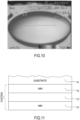
- Figure 10 shows a thermal image captured by means of a thermal camera and referring to a specific embodiment of the plate 1 according to the present disclosure, being irradiated by an electromagnetic radiation at 2,45 GHz in a microwave oven.
- the zones of the image being darker are colder than the zones of the image being whiter. It is apparent that the central substantially flat portion of the plate 1 is substantially uniform in temperature.
- the plate 1 being provided with the at least one coating layer 1c as above described is configured to keep a temperature difference between an hottest portion of the plate 1 and a coldest portion of the plate 1 within the range 20°C - 80°C, preferably within the range 30°C - 70°C, more preferably within the range 40°C - 60°C.
- Figure 11 discloses a further embodiment of the plate according to the present disclosure (presented in particular as a variant to the embodiment of figure 4 ).
- the plate 1 comprises a substrate layer 1s that has the features already disclosed in the present document, which therefore are not repeated.
- This latter embodiment comprises at least a first coating layer 1c which is provided with a first layer 1c', a second layer 1c" and an auxiliary layer 1a.
- the first layer 1c' and the auxiliary layer 1a comprise a boron nitride compound, which is configured to cause a substantial distribution of heat induced, in use, by the electromagnetic radiation irradiated by the microwave oven 10.
- the thickness of the auxiliary layer 1a measured along a direction that is substantially orthogonal to the plane along which the auxiliary layer 1a mainly extends, is substantially constant.
- the section of the plate 1 is composed as follows.
- the top layer is formed by the substrate layer 1s. This latter is juxtaposed to the auxiliary layer 1a comprising the boron nitride compound.
- the auxiliary layer 1a is juxtaposed to the second layer 1c", and thus results sandwiched between the substrate layer 1s (at the top) and the second layer 1c" (at the bottom).
- the second layer 1c" is juxtaposed to the first layer 1c'.
- the second layer 1c" is sandwiched between the first layer 1c' and the auxiliary layer 1a.
- FIG 11 shows that the coating layer 1c provided with the auxiliary layer 1a is only provided below the substrate layer 1s, it may be noted that according to a further non-limiting embodiment the coating layer 1c provided with such auxiliary layer 1a may be also provided, or alternatively provided, above the substrate layer 1s.
- Venting openings and/or tiles as above described may be provided in the coating layer 1c also when this latter is provided with the auxiliary layer 1a. In this latter case, it may be noted that the venting openings 1v may extend from the first layer 1c up to the auxiliary layer 1a.
- the present invention is open to several variants wherein above described layers are alternated in different ways.
- a variant may be contemplated wherein layers comprising the boron nitride compound are alternated to layers comprising the ferritic material.
- the present invention may contemplate several sandwich structures for the coating of the plate 1, wherein the elements of the sandwich structures are in particular the base matrix with the ferrites, the boron nitride film and the carbon nanotubes.
- the elements of the sandwich structures are in particular the base matrix with the ferrites, the boron nitride film and the carbon nanotubes.
- a sandwich structure formed by base matrix ferrite layers and boron nitride film layers alternating with each other may be envisaged.
- a further sandwich structure wherein several layers of base matrix are covered (internally and/or externally) by a boron nitride layer may be envisaged as well.
- the plate 1 is capable of being heated very efficiently by microwaves radiation and this helps in reducing the power required to properly heat food from the bottom part thereof in a microwave oven.
- the efficient heating obtained by the coating layer of the plate 1 here described indirectly allows to lengthen the lifetime of the magnetron of the microwave oven, since for a same reached cooking temperature, the amount of power required by the magnetron is lower than that is required with supporting plates of the known art.
- the plate 1 helps achieving high-energy efficiency rates; in such a way, when the plate 1 is arranged in the microwave oven, the overall assembly realized by the microwave oven and the plate 1 complies easily with even stringent energy efficiency regulations.
- the plate 1 helps in providing a proper food cooking and mitigates the risk of overcooking of the lateral and top portion of foods with respect to the lower portion of the food.
- the plate 1 helps to achieve a proper uniform cooking and/or browning of the food especially when in use is rotated by the support in the muffle of the microwave oven.
- the plate 1 according to the present disclosure heats fast, and thus a small amount of time is required to achieve a proper cooking temperature of the bottom of the food.
- the plate 1 according to the present disclosure has a very effective heating distribution behavior and, in particular, a very effective heating uniformity behavior; this reduces the impact of the food positioning on the plate 1 on the achievement of an optimal cooking.
- the plate 1 according to the present disclosure is food-compatible, and therefore no issues are present in case any food is directly put in contact with the plate 1, especially with the coating layer 1c and/or with the substrate layer 1s.
- the plate 1 is hence immune from any toxicity threats.
- the plate 1 according to the present disclosure is advantageously conceived in such a way to reduce the risk of permanence of air bubbles within, or between, the layers of the substrate or of the coating. This reduces the risk of detachment of the coating layer from the substrate layer when the plate 1 is heated.
- the plate 1 is realized with materials that allow a cost-saving production and that allow to obtain very smooth surfaces, that provide an overall quality aspect when seen by a user.
- the thickness of the coating layer 1c of the plate 1 according to the present disclosure can be further reduced with respect to the thickness of the coating layers of the known art without compromising the effectiveness of the heating distribution.
- the thermal stability of the coating layer 1c is improved, and this contributes to lengthen the lifetime of the plate 1, mitigating the risk of detachment of the coating layer 1c with respect to the substrate layer 1s.
- the plate 1 according to the present disclosure is very durable.
- the plate 1 according to the present disclosure may be washed in a dishwasher with substantially no risk of significant affection or damaging to the coating layer.
Landscapes
- Physics & Mathematics (AREA)
- Electromagnetism (AREA)
- Engineering & Computer Science (AREA)
- Food Science & Technology (AREA)
- Cookers (AREA)
- Electric Ovens (AREA)
Abstract
Description
- The present invention relates to the technical field of the household appliances, in particular the technical field of the microwave ovens and parts thereof. More precisely, the present invention relates to a plate or a dish for supporting, in a microwave oven, food items during a heating or a cooking or a thawing process. Such plate or dish is generally known as "crisp plate" in the technical field of the present disclosure.
- In the recent years, microwave ovens have diffused widely also thanks to the increase of their efficiency and of the possibility of cooking also complex foods provided by advanced functions that in past were not available for this kind of ovens.
- The microwave ovens are provided with a muffle wherein a supporting plate, also known as "crisp plate" is provided. The supporting plate is configured to be heated by means of the electromagnetic radiation that the microwave oven in use radiates in the muffle.
- The supporting plate is realized with a material that, once irradiated by an electromagnetic radiation, heats and diffuses the heat to the food; therefore, the supporting plate helps providing a heat source for assisting the cooking of the food from the bottom part thereof. The supporting plate may be configured to cause a browning of the food.
- Electromagnetic radiation is generated typically by means of a magnetron arranged outside, but close to, the muffle and the radiation is directed to the muffle by means of a waveguide. Today's microwave ovens cook food by irradiating microwaves typically in the range of 2 - 3 GHz, and precisely exploiting the 2,4 - 2,5 GHz band, at least for compliance to national regulations and for the effectiveness these wavelengths have for heating foods.
- Known supporting plates comprise a ferritic coating. The purpose of the ferritic coating is to be heated by the microwaves irradiated by the oven. The known supporting plates are subject to some drawbacks. Specifically, the known supporting plates have a limiting capability of absorbing microwave radiations, and this limits the amount of heat that they are able to generate. In other words, for reaching a predetermined target temperature, they require a significant amount of electromagnetic radiation power, which may overcook the food. Overcooking of the food may cause a substantial burning, far beyond a wished browning.
- In addition, this causes a waste of energy: the microwave oven absorbs more current than that it could be required should the supporting plate properly and highly heat due to microwaves absorption. This, indirectly, causes a shortening of the expected lifetime of the magnetron. As a further side effect, this causes an increase in the time required to obtain a proper cooking of the food.
- Moreover, the known supporting plates shown poor capacity of uniformly distributing the heat across their surfaces. A non-uniform distribution of the heat results in some spots or limited areas of the supporting plate being far hotter than others. This impacts on the quality of cooking, since it is known that for the vast majority part of cooking techniques, an uniform cooking temperature of the food is preferable in order to mitigate the risk of obtaining a food wherein some parts are not properly heated and/or wherein some other parts are overcooked or even burnt.
- For a proper heating the materials with which the supporting plates are realized shall have a precise Curie temperature that shall comply with the application. Limitations of the Curie temperature may cause a serious alteration of the behavior of the material, and cause poor heat spreading properties. The cooking, in particular the browning of food in a supporting plate is related to the Curie temperature of the compounds forming the plate, and is in particular related to the Curie temperature of the layer that is conceived to generate heat when invested by the microwaves radiation.
- Some supporting plates are at least partially realized in ceramic, which has shown a substantial transparency to the electromagnetic radiations at frequencies typically emitted by today's magnetrons. This implies that for achieving a proper cooking of the food from a bottom part thereof, an extra power is required to the magnetron.
- Apart from the energy wasting in pure terms of physics, it is noted that an important parameter for today's production of household appliances, including microwaves, is the compliance to energy efficiency regulations, among which there is Energy Star. A poor energy management and/or requirement impacts on the compliance the oven has with respect to energy efficiency regulations.
- The Applicant notes that the known supporting plates provide for a substrate having relevant mechanical properties and a coating for causing the heating of the plate. The known coatings require relevant thickness and expensive processing techniques.
- It may be further noted that the coating may not trap bubbles. In fact, in this latter case, the air contained in the bubbles may heat thereby causing a cracking of the coating, that therefore may detach from the underlying substrate layer.
- European patent
EP3654736B1 (in the name of Whirlpool Corporation ) discloses a liner for a crisp plate including ceramic nanoparticles in a polymer matrix, with carbon nanoparticles embedded and aligned therein. The polymer matrix of the crisp plate is a two-part pre-polymerized polymer. The carbon nanoparticles are enclosed in a liner that further comprises aluminum particles and nanocrystalline ceramic nanoparticles. - It has been found that due to the conductive nature of the aluminum the coating of the known crisp plates is not efficient enough against microwaves radiation absorption, especially when the microwaves are at a frequency of 2.45GHz.
- An aim of the present disclosure is to provide a plate for a microwave oven, capable of overcoming or at least mitigating the drawbacks of the known supporting plates.
- The present disclosure refers to a peculiar plate conceived for overcoming the drawbacks of the known art and whose principal features are disclosed in the following aspects. The following aspects can be combined together and/or with portions of the detailed description and/or with the following claims.
- According to a first aspect, it is herewith disclosed a plate (1) for a microwave oven (10), comprising a substrate layer (1s) configured for supporting food items to be cooked in said microwave oven (10) and at least a first coating layer (1c) at least partially juxtaposed and in contact with the substrate layer (1s), wherein the coating layer (1c) is configured to be heated by means of an electromagnetic radiation in use irradiated by the microwave oven (10) and wherein the coating layer (1c) is a multilayer coating comprising at least a first layer (1c') and a second layer (1c"); the coating layer (1c) comprising at least one between a ferritic material and a boron nitride compound.
- According to a further non-limiting aspect, the coating layer (1c) is configured to be heated when is irradiated by an electromagnetic radiation having a frequency in the field of the microwaves, preferably within the 2 - 3 GHz band, more preferably within the 2,4 - 2,5 GHz band.
- According to a further non-limiting aspect, the first layer (1c') comprises said boron nitride compound and the second layer (1c") comprises said ferritic material.
- According to a further non-limiting aspect, the first layer (1c') is a superficial layer.
- According to a further non-limiting aspect, the second layer (1c") is a buried layer.
- According to a further non-limiting aspect, the plate (1) comprises a contacting surface between the substrate layer (1s) and the at least a first coating layer (1c), wherein the contacting surface is substantially planar.
- According to a further non-limiting aspect, the plate (1) comprises a contacting surface between the first layer (1c') and the second layer (1c"), said contacting surface being substantially planar.
- According to a further non-limiting aspect, the second layer (1c") is sandwiched between the first layer (1c') and the substrate layer (1s).
- According to a further non-limiting aspect, the substrate layer (1s) comprises an electrically insulating material, said electrically insulating material comprising glass ceramic and/or glass-fiber reinforced-plastics.
- According to a further non-limiting aspect, the second layer (1c") comprises a polymeric matrix, the polymeric matrix comprising a silicone.
- According to a further non-limiting aspect, the silicone comprises a silicone rubber, preferably a RBL-9050-50P Liquid Silicone Rubber.
- According to a further non-limiting aspect, the polymeric matrix comprises said silicone rubber in a mixing ratio of 10 to 1 with a catalyst.
- According to a further non-limiting aspect, the polymeric matrix comprises a bi-component pre-polymerized polymer.
- According to a further non-limiting aspect, the second layer (1c") is a composite ferritic-polymer-carbon layer.
- According to a further non-limiting aspect, the first layer (1c') is an outer, superficial, layer.
- According to a further non-limiting aspect, the second layer (1c") is in contact with the substrate layer (1s).
- According to a further non-limiting aspect, said second layer (1c") is interposed between the substrate layer (1s) and the first layer (1c').
- According to a further non-limiting aspect, the second layer (1c") comprises a carbon material.
- According to a further non-limiting aspect, the second layer (1c") is a composite layer wherein the carbon material is blended, optionally uniformly blended, with the ferritic material.
- According to a further non-limiting aspect, the carbon material comprises carbon nanotubes.
- According to a further non-limiting aspect, the ferritic material comprises ferromagnetic nanowires.
- According to a further non-limiting aspect, the carbon material comprises a carbon ferritic powder.
- According to a further non-limiting aspect, said carbon ferritic powder has a Curie temperature of about 210 °C.
- According to a further non-limiting aspect, the carbon nanotubes are blended with said ferritic material, optionally with said ferromagnetic nanowires.
- According to a further non-limiting aspect, the carbon nanotubes are blended with said ferritic material, optionally with said ferromagnetic nanowires, in an amount of 1.0 wt% to 6 wt%, preferably 1.5 wt% to 5.5 wt% and/or in such a way to keep the second layer (1c") substantially electrically insulating.
- According to a further non-limiting aspect, the ferritic material comprises at least one of the compounds of the following list: a nickel-manganese ferritic compound, a nickel-copper-zinc ferritic compound, a manganese-zinc ferritic compound.
- According to a further non-limiting aspect, the nickel-manganese ferritic compound comprises a Ni0,5Mn0,5F2O4 compound.
- According to a further non-limiting aspect, the Ni0,5Mn0,5F2O4 compound has a Curie temperature of about 350° C.
- According to a further non-limiting aspect, the manganese-zinc ferritic compound comprises a (MnxZnyFe2 +1 -x-y)Fe3 +2O4 compound.
- According to a further non-limiting aspect, the nickel-copper-zinc ferritic compound is a Ni0.60-yCuyZn0.42Fe1.98O0,39 compound, optionally comprising Bi2O3.
- According to a further non-limiting aspect, said at least a first coating layer (1c) comprises an auxiliary layer (1a).
- According to a further non-limiting aspect, the thickness of the auxiliary layer (1a) is substantially constant.
- According to a further non-limiting aspect, the auxiliary layer (1a) is in substantial contact with the substrate layer (1s).
- According to a further non-limiting aspect, the first layer (1c') and the auxiliary layer (1a) comprise said boron nitride compound.
- According to a further non-limiting aspect, said boron nitride compound is configured to cause a substantial distribution of heat induced, in use, by the electromagnetic radiation irradiated by the microwave oven (10) and/or is configured to keep a temperature difference between an hottest portion of said plate (1) and a coldest portion of said plate (1) within the
range 20°C - 80°C, preferably within the range 30°C - 70°C, more preferably within therange 40 °C - 60 °C. - According to a further non-limiting aspect, said first layer (1c') is arranged at a first side of the second layer (1c") and the auxiliary layer (1a) is arranged at a second side of the second layer (1c").
- According to a further non-limiting aspect, the first side is opposite to the second side.
- According to a further non-limiting aspect, the auxiliary layer (1a) is in contact with the substrate layer (1s).
- According to a further non-limiting aspect, the at least a first coating layer (1c) has a textured surface.
- According to a further non-limiting aspect, the at least a first coating layer (1c) comprises a plurality of tiles (1t) abutting from the substrate layer (1s) or comprises a plurality of venting openings (1v) configured for allowing a venting of any gaseous residue trapped in the at least a first coating layer (1c) and/or in the substrate layer (1s).
- According to a further non-limiting aspect, at least part of said plurality of tiles (1t) has a thickness of 1,5mm to 3,5mm, preferably of 2mm to 3mm, more preferably of 2.5mm to 2.75mm.
- According to a further non-limiting aspect, the at least a first coating layer (1c) has a thickness of 1mm to 4.5mm, preferably 1.5mm to 4mm, more preferably 2mm to 3.5mm, even more preferably 2.5mm to 3mm.
- According to a further non-limiting aspect, the substrate layer (1s) has a first thickness and the at least a first coating layer (1c) has a second thickness; the first thickness being greater than the second thickness.
- According to a further non-limiting aspect, the plate (1) comprises a second coating layer (1c).
- According to a further non-limiting aspect, the first coating layer (1c) is arranged at a first side of the substrate layer (1s) and the second coating layer (1c) is arranged at a second side of the substrate layer (1s), the second side being opposite to the first side.
- According to a further non-limiting aspect, the plate (1) comprises a first contacting surface (2) between the substrate layer (1s) and the second coating layer (1c) and comprises a second contacting surface (3) between the substrate layer (1s) and the first coating layer (1c); at least one between the first contacting surface (2) and the second contacting surface (3) being substantially planar and/or being substantially parallel to the contacting surface that lays between the first layer (1c') and the second layer (1c").
- According to a further non-limiting aspect, the coating layer (1c) is configured to reach at least a surface temperature of 200 °C, preferably at least of 210°C, more preferably at least of 220°C in 3 minutes, when heated by a microwave oven (10) irradiating an electromagnetic radiation at a power of at least 750W or of at least 950W, and/or wherein the coating layer (1c) is a food-compatible coating layer.
- According to a further non-limiting aspect, the first coating layer (1c) comprises an auxiliary layer (1a) and the second coating layer (1c) comprises an auxiliary layer (1a).
- According to a further non-limiting aspect, the auxiliary layer (1a) of the first coating layer (1c) and the auxiliary layer (1a) of the second coating layer (1c) are in contact with the substrate layer (1s).
- According to a further non-limiting aspect, the second coating layer (1c) comprises a plurality of tiles (1t) abutting from the substrate layer (1s) or comprises a plurality of venting openings (1v) configured for allowing a venting of any gaseous residue trapped in the at least a first coating layer (1c) and/or in the substrate layer (1s).
- According to a further non-limiting aspect, the substrate layer (1s) and/or the at least a first coating layer (1c), optionally the first coating layer (1c) and the second coating layer (1c), and/or the first layer (1c') and the second layer (1c") of the first and/or of the second coating layer (1c) have a substantially uniform thickness.
- According to a further non-limiting aspect, the plate (1) comprises a central, at least partially flat, portion and an external portion (1k), raised with respect to the central substantially flat portion or raising from the central, at least partially flat, portion.
- According to a further non-limiting aspect, the external portion (1k) defines a perimetric raised ring or wall suitable to allow the plate (1) contain substantially fluid and/or liquid food.
- According to a further non-limiting aspect, the external portion (1k) defines at least one wall that is inclined with respect to the central, at least partially flat, portion.
- According to a further non-limiting aspect, the external portion (1k) is substantially orthogonal with respect to the central, at least partially flat, portion.
- According to a further non-limiting aspect, the plate (1) is self-sustaining.
- According to a further aspect, it is herewith disclosed a microwave oven (10) comprising a plate (1) according to one or more of the aspects herein described.
- The invention will be described with a reference to the annexed figures. A brief description of the figures is hereinafter presented.
-
Figure 1 shows a schematic view of a microwave oven provided with a plate according to the present disclosure. -
Figure 2 shows a section view of the plate according to the present disclosure. -
Figure 3 shows a section view of the coating layer of an embodiment of the plate according to the present disclosure. -
Figure 4 shows a section view of a coating layer of the plate according to the present disclosure. -
Figure 5 shows a section view of a further embodiment of the plate according to the present disclosure. -
Figure 6 shows a section view of a further embodiment of the plate according to the present disclosure. -
Figure 7 shows a section view of a further embodiment of the plate according to the present disclosure. -
Figure 8 shows a diagram of temperatures reached by several embodiments of the plate over time. -
Figure 9 shows a diagram of temperature differentials over time of several embodiments of the plate. -
Figure 10 shows a thermal image of the plate heated by a radiofrequency source. -
Figure 11 shows a further embodiment of the plate according to the present disclosure. -
Reference number 1 shows a plate for a microwave oven (the device referenced with thenumber 1 may also be defined as a dish because the terms "plate" and "dish" shall be seen as synonyms in the present description). Theplate 1 is configured to support food to be heated by a microwave oven, in particular by the electromagnetic radiation in use irradiated by themicrowave oven 10. Theplate 1 of the present disclosure is in particular a so-called "crisp plate", configured to allow the browning of the food therein contained when the plate is irradiated with a microwave electromagnetic radiation. - As shown in
figure 1 , theplate 1 is configured to be housed in themuffle 11 of themicrowave oven 10, which further includes a support for theplate 1 which is installed on the bottom 11f of themuffle 11. The support is configured to cause the rotation thereof around an axis that, in use, is substantially vertical (and consequently the rotation of the plate 1). The rotation of the plate (caused by the rotation of the support) may be useful for obtaining a uniform cooking of the food, in particular in those cases wherein - e.g. due to the physical configuration of the waveguide that opens in the muffle - it is not possible to achieve a symmetrical and or uniform distribution of the electromagnetic radiations in themuffle 11. - The
microwave oven 10 comprises a microwave source (in particular a magnetron) configured for generating an electromagnetic radiation, a cavity (in particular a muffle 11 internal to the casing of themicrowave oven 10 and closable through a door 12) configured for accommodating food items to be heated or cooked or thawed and guiding means (in particular a waveguide) configured for allowing the electromagnetic radiation to be transferred from the microwave source to the cavity.Figure 1 further shows some schematic details of the microwave oven 10: a control unit and/oruser interface 14, configured to allow the user select and/or see at least one among a proper cooking program, electromagnetic radiation power, cooking time, ventilation of themuffle 11, remaining cooking time, activation or deactivation of the oven. Themicrowave oven 10 further comprises adoor 12, which preferably is provided with atransparent section 13, in particular a glass pane, conceived for allowing the user see the food while cooking when thedoor 12 is closed. - The aim of the
plate 1 is to enhance the uniform heating of the food and the heating efficiency of microwave oven for improving the cooking performances. -
Figure 2 shows a section of theplate 1 according to the present disclosure. As it can be seen, theplate 1 comprises a central substantially flat portion and an external raisedportion 1k. In an embodiment, which is clearly not limiting albeit preferable, theplate 1 presents a substantially axisymmetric shape. This means that, in this specific embodiment, the external raisedportion 1k defines a perimetric raised ring or wall suitable to allow theplate 1 to contain substantially fluid and/or liquid food, while mitigating the risk of dispersion during the cooking in themuffle 11. - The external raised
portion 1k defines at least one wall that is inclined with respect to the central substantially flat portion. In an embodiment, the external raisedportion 1k may be substantially orthogonal with respect to the central substantially flat portion. -
Figure 3 shows a first embodiment of theplate 1 according to the present invention and in detail proposes a detailed view of the layers composing theplate 1.Figure 3 could be seen as a section according to line A-A offigure 2 of a portion of theplate 1. - In the embodiment of
figure 3 , it can be seen that theplate 1 comprises asubstrate layer 1s configured for supporting food items to be cooked in themicrowave oven 10. In particular, thesubstrate layer 1s is configured to have a robustness and/or has a rigidity sufficient to realize a self-sustaining shape of theplate 1 even without the help of any further layer. In other words, thesubstrate 1 is configured to sustain at least the weight of the food that is typically cooked in a microwave oven. - The thickness of the
substrate layer 1s is chosen by the technician in accordance to the overall size of theplate 1. Preferably, albeit in a non-limiting extent, the thickness of thesubstrate layer 1s, measured along a direction that is substantially orthogonal to the plane along which thesubstrate layer 1s mainly extends, is substantially constant. - The
plate 1 comprises at least afirst coating layer 1c configured to be heated by means of the electromagnetic radiation in use irradiated by themicrowave oven 10. In particular, the purpose of thecoating layer 1c is to generate heat when invested by the electromagnetic radiation irradiated by the microwave oven. In particular, the material of thecoating layer 1c is suitable to generate heat when invested by an electromagnetic radiation in the field of the microwaves (300 MHz to 300 GHz). The Applicant notes that, in general, consumer microwave ovens exploit the ISM microwaves band of 2,4 - 2,5 GHz (formally, the carrier lays at 2,45 GHz), and for such reason thecoating layer 1c may be preferably particularly configured to generate heat when radiated by a radiation in the 2 - 3 GHz band. - Albeit this shall not be considered limiting, a preferred thickness of the
coating layer 1c lies in the range 1mm to 4.5mm, preferably 1.5mm to 4mm, more preferably 2mm to 3.5mm, even more preferably 2.5mm to 3mm. In an embodiment, thecoating layer 1c is obtained through injection moulding (this however shall not be seen as a limitation since thecoating layer 1c may alternatively applied e.g. by being sprayed on thesubstrate layer 1s). - Given a first thickness for the
substrate layer 1s and given a second thickness for thecoating layer 1c, in a preferred and non-limiting embodiment, the first thickness is greater than the second thickness. - Preferably, albeit in a non-limiting extent, the thickness of the
coating layer 1c, measured along a direction that is substantially orthogonal to the plane along which thecoating layer 1c mainly extends, is substantially constant. - The material with which the at least a
first coating layer 1c is realized exhibits a selected Curie temperature lower than the desirable maximum temperature which is required by a proper food cooking. - The Curie temperature is the temperature beyond which a ferromagnetic material loses some intrinsic properties as the non-univocal correspondence between the external field and magnetization and therefore behaves similarly to a paramagnetic material.
- The choice of materials having a proper Curie temperature is important to allow a proper cooking of the food in the microwave oven. In fact, in use, with the irradiation of the
plate 1 by means of a microwave electromagnetic radiation, below the Curie temperature there is an energy absorption that causes an increase of the temperature of the material. In contrast, when the heating of the material causes its temperature to exceed the Curie temperature, independently of the electromagnetic radiation the energy absorption will substantially cease; in the areas of the material wherein the Curie temperature is exceeded, the conduction of heat is substantially stopped. The overall behavior of theplate 1 is such that it can reach a temperature ranging between 250°C and 290°C, more preferably, between 260°C and 280°C when subjected to a microwave electromagnetic radiation having a frequency in the range 2 - 3 GHz, more preferably in therange 2,4 - 2,5 GHz at a power of 900 - 950 W. - A contacting surface is defined between the at least a
first coating layer 1c and thesubstrate layer 1s, this contacting surface being substantially planar; this helps reducing the risk that some air bubbles remain trapped between the two layers. - The
coating layer 1c is specifically configured to improve the heat spreading, the spreading uniformity and the heating rate of theplate 1 when irradiated by such electromagnetic radiation. - In detail, the
coating layer 1c is a multilayer coating and comprises at least afirst layer 1c' and asecond layer 1c". Thecoating layer 1c comprises at least one between a ferritic material and a boron nitride compound. Boron nitride (hBN) is an optimal choice when there is a requirement of heating by means of an electromagnetic radiation, especially within the 2 - 3 GHz band. In an embodiment, a substantially planar contacting surface is defined between thefirst layer 1c' and thesecond layer 1c". - Preferably, albeit in a non-limiting extent, the thickness of the
first layer 1c', measured along a direction that is substantially orthogonal to the plane along which thefirst layer 1c' mainly extends, is substantially constant. As well, the thickness of thesecond layer 1c", always measured along a direction that is substantially orthogonal to the plane along which thesecond layer 1c" mainly extends, is substantially constant. - Preferably, albeit in a non-limiting extent, the ferritic material comprises a manganese-zinc ferritic compound or a nickel-manganese ferritic compound or even a nickel-copper-zinc ferritic compound. Several embodiments of those two types of compound have been studied and selected for tests by the Applicant. Among those several embodiments, in particular the Ni0,5Mn0,5F2O4 compound, the family (MnxZnyFe2 +1 -x-y)Fe3 +2O4 of manganese-zinc ferritic compounds and the Ni0.60-yCuyZn0,42Fe1,98O0,39 compound are ferritic compounds having Curie temperatures compatible with the scope of allowing a proper cooking, eventually browning, of the food.
- In an embodiment, any of the aforementioned compounds, especially the Ni0.60-yCuyZn0,42Fe1,98O0,39 compound, may optionally comprise Bi2O3. The Ni0,5Mn0,5F2O4 compound has a Curie temperature of about 350° C.
- Between the at least two
layers 1c', 1c" forming thecoating layer 1c, thefirst layer 1c' is an outer, superficial layer, and thesecond layer 1c" is an inner (or buried) layer and is in contact with thesubstrate layer 1s. This means that thefirst layer 1c' of thecoating layer 1c is the layer that the user may touch when manipulating theplate 1 and that may also be in contact with the food, so that thefirst layer 1c' can advantageously have food-compatibility properties. - In an advantageous embodiment of the present disclosure (shown in
figure 3 ), thecoating layer 1c is applied only to the lower surface of thesubstrate layer 1s, i.e. only to the surface of thesubstrate layer 1s opposite to the surface destined for coming into contact with the food. - The Applicant specifically notes that, even if the schematic section of
figure 3 shows thecoating layer 1c laying below thesubstrate layer 1s, the present invention shall not be intended as to be limited in that thecoating layer 1c, in use conditions of theplate 1, is necessarily below thesubstrate layer 1s. Indeed, the plate 1 (due to the food-compatibility of thecoating layer 1c) may alternatively have thecoating layer 1c above thesubstrate layer 1s in the conditions of use, i.e. in the spatial orientation depicted infigure 2 wherein the concavity of the plate is directed upwards. - The
substrate layer 1s may be made of metal, e.g. aluminum. In a preferred and non-limiting embodiment, thesubstrate layer 1s is at least partially made of an electrically insulating material and, in particular, comprises a glass ceramic material and/or a glass-fiber reinforced plastic. This latter material provides a good electric insulation, which is important when theplate 1 is irradiated with such electromagnetic radiation generated by the magnetron of the microwave oven (since otherwise it may conduct the electric current induced by the electromagnetic radiation), and provides also a sufficient robustness to support the weight of the food. Moreover, the glass ceramic material has a very low reacting behavior with any acid or basic substance that may be found in foods. - In the specific embodiment shown in
figure 4 , thefirst layer 1c' comprises a boron nitride (hBN) compound. - The
second layer 1c" comprises a polymeric matrix, being provided with a silicone. In a preferred, non-limiting embodiment, one type of polymer considered to be suitable for the coating of the present concept is RBL-9050-50P Liquid Silicone Rubber. Two-pair, 10 to 1 mix, clear, fabric coating grade liquid silicone rubber offers unique homogeneous mixing. This two-part pre-polymerized polymer composite is the 10 to 1 mix, clear, fabric coating grade liquid silicone rubber which has an extremely low viscosity, no post-curing requirements, and excellent electrical insulating properties. Furthermore, the two-part pre-polymerized polymer composite is equally suitable for spray-on and dip coating applications. The 10 to 1 mix of this polymer refers to the 10 to 1 base to catalyst 87-RC ratio of the polymer. - The Applicant has tested several embodiments for the
second layer 1c" comprising a predefined ratio between the ferritic powders and the polymer, especially the silicone. The tests were conducted with percentage ratios by weight (wt%) between the ferritic powders and silicones between 70:30 and 90:10, and in particular with percentage ratios by weight (wt%) between the ferritic powders and silicones between 75:25 and 85:15. Tests were conducted with both solid and liquid silicones. Hereinafter an excerpt of four tests performed by the Applicant is proposed. - Test 1: in one non-limiting embodiment the percentage ratio by weight (wt%) between the ferritic powders and the silicone was 78:22; in
test 1, the silicone was solid silicone. - Test 2: in another non-limiting embodiment the percentage ratio by weight (wt%) between the ferritic powders and the silicone was 80:20; in
test 2, the silicone was solid silicone. - Test 3: in another non-limiting embodiment, the percentage ratio by weight (wt%) between the ferritic powders and the silicone was 82:18; in
test 3, the silicone was solid silicone. - Test 4: in another non-limiting embodiment, the percentage ratio by weight (wt%) between the ferritic powders and the silicone was 82:18; in
test 4, the silicone was liquid silicone. - In a preferred, non-limiting embodiment, the polymeric matrix comprises a bi-component, pre-polymerized polymer. Precisely, the
second layer 1c" may result as a composite ferritic-polymer-carbon layer. - In the specific embodiment shown in
figure 4 , thesecond layer 1c" comprises the Ni0,5Mn0,5F2O4 compound and preferably is constituted by the Ni0,5Mn0,5F2O4 compound, excepting impurities. - In another embodiment, not shown in figures, the
second layer 1c" comprises the family (MnxZnyFe2 +1 -x-y)Fe3 +2O4 of manganese-zinc ferritic compounds and preferably is constituted by the family (MnxZnyFe2 +1 -x-y)Fe3 +2O4 of manganese-zinc ferritic compounds, excepting impurities. - The Ni0,5Mn0,5F2O4 compound, or the family (MnxZnyFe2 +1 -x-y)Fe3 +2O4 of manganese-zinc ferritic compounds, and the polymeric matrix are blended together.
- The
second layer 1c" of thecoating layer 1c further comprises also a carbon material which is further blended, in particular uniformly blended, with the ferritic material. In detail, the embodiment offigure 4 shows that thesecond layer 1c" comprises the Ni0,5Mn0,5F2O4 compound uniformly blended with the carbon material. - Another embodiment comprises the
second layer 1c" being provided with any of the compounds of the family (MnxZnyFe2 +1 -x-y)Fe3 +2O4 of manganese-zinc ferritic compounds blended with the carbon material. Another embodiment comprises thesecond layer 1c" being provided with the Ni0.60-yCuyZn0,42Fe1,98O0,39 compound blended with the carbon material. - In an embodiment, which is non-limiting, the carbon material comprises a carbon ferritic powder. The carbon ferritic powder exhibits a low Curie temperature, which lays around 210°C.
- In terms of structure of the components of the
coating layer 1c, the Applicant studied several types of carbon materials and realised that a particularly efficient material may comprise carbon nanotubes. As well, the Ni0,5Mn0,5F2O4 compound or any of the compounds of the family (MnxZnyFe2 +1 -x-y)Fe3 +2O4 of manganese-zinc ferritic compounds, or even the Ni0.60-yCuyZn0.42Fe1.98O0,39 compound, may comprise ferromagnetic nanowires. Exploiting nanotubes and nanowires properties allows realizing very precise, dense layers, whose property of heating distribution is uniform. As well, exploiting nanotubes and nanowires allows realizing a uniform surface of the layers, which therefore can be sandwiched together in a very precise way. Furthermore, exploiting nanotubes and nanowires properties allows realizing also very thin layers. Albeit this shall not be considered limiting, the nanotubes may be single-walled nanotubes or double-walled nanotubes. In an embodiment, the nanotubes may have a common, or unidirectional, orientation. - The Applicant realised as well that, when the
plate 1 is heated by the electromagnetic radiation, an optimization of the performances of heating rate and distributioncan be obtained by choosing specific ranges of weight ratios between the carbon material and the ferritic materials. - In detail, in an embodiment, in the
second layer 1c" the carbon material is blended with the ferritic material in an amount of 1.0 wt% to 6.0 wt%. With the wording "wt%" it is intended percentage by weight. Specifically, in thesecond layer 1c" the carbon material is blended with the Ni0,5Mn0,5F2O4 compound, or alternatively with any of the compounds of the family (MnxZnyFe2 +1 -x-y)Fe3 +2O4 of manganese-zinc ferritic compounds, or even alternatively with the Ni0.60-yCuyZn0.42Fe1.98O0,39 compound, optionally comprising Bi2O3, in an amount of 1.0 wt% to 6.0 wt%. This means that the ratio between the carbon material and the ferritic material may be, at the ends of the aforementioned ranges, 1.0 wt% of carbon material and 99.0 wt% of ferritic material or, at the opposite end of the range, 6.0 wt% of carbon material and 94.0 wt% of ferritic material. - Preferably, albeit in a non-limiting extent, in the
second layer 1c" the carbon material is blended with the ferritic material in an amount of 1.5 wt% to 5.5 wt%. Specifically, in thesecond layer 1c" the carbon material is blended with the Ni0,5Mn0,5F2O4 compound, or alternatively with any of the compounds of the family (MnxZnyFe2 +1 -x-y)Fe3 +2O4 of manganese-zinc ferritic compounds, or even alternatively with the Ni0.60-yCuyZn0,42Fe1,98O0,39 compound, optionally comprising Bi2O3, in an amount of 1.5 wt% to 5.5 wt%. This means that the ratio between the carbon material and the ferritic material may be, at the ends of the aforementioned ranges, 1.5 wt% of carbon material and 98.5 wt% of ferritic material or, at the opposite end of the range, 6.5 wt% of carbon material and 93.5 wt% of ferritic material. - The purpose of the aforementioned blending ratio is to keep at least the
second layer 1c" substantially electrically insulating and/or showing, when irradiated with the electromagnetic radiation within the specifications as above disclosed, an optimal heating behavior when invested by a field of electromagnetic fields oscillating in the microwaves domain. -
Figure 5 shows an alternative embodiment of theplate 1 herein disclosed, wherein thesubstrate layer 1s is sandwiched between two coatinglayers 1c. In fact, inFigure 5 it may be appreciated that afirst coating layer 1c is arranged above thesubstrate layer 1s and that asecond coating layer 1c is arranged below thesubstrate layer 1s. - In
figure 5 , thereference number 2 identifies a contacting surface between thesubstrate layer 1s and thefirst coating layer 1c laying below thesubstrate layer 1s and thereference number 3 identifies a contacting surface between thesubstrate layer 1s and thesecond coating layer 1c laying above thesubstrate layer 1s. Precisely, the first and the second coating layers 1c are arranged respectively at a first and at a second side of thesubstrate layer 1s and the first side and second side are opposite one with respect to the other. Those contacting surfaces are substantially planar, or at least have a plurality of planar portions allowing a proper contact with the juxtaposed layer. - Preferably, albeit in a non-limiting extent, at least one between the first contacting
surface 2 and the second contactingsurface 3 is substantially planar and/or is substantially parallel to the contacting surface that lays between thefirst layer 1c' and thesecond layer 1c". - In an embodiment, the first and the second coating layers have the same composition of materials; in another embodiment the first and the second coating layers may have a different composition of materials, especially concerning the composition of their
second layers 1c", which in an embodiment may comprise different ferritic materials. The first and the second coating layers 1c have both the respectivefirst layer 1c' comprising boron nitride (hBN) as above described. Said boron nitride can actually be hexagonal boron nitride. - The
coating layer 1c may have a flat surface or a textures surface.Figure 6 shows a particular embodiment of theplate 1 of the present disclosure. Acoating layer 1c in form of a plurality oftiles 1t is applied to thesubstrate layer 1s. The composition of thecoating layer 1c is the same as above described, and thus it is not completely repeated here. It is herewith remarked that all thetiles 1t have the first and thesecond layers 1c', 1c" as above described. Albeit this shall not be considered limiting, at least part of the plurality oftiles 1t has a thickness of 1,5mm to 3,5mm, preferably of 2mm to 3mm, more preferably of 2.5mm to 2.75mm. - In an embodiment, all
tiles 1t of theplate 1 have the same composition of materials. In another embodiment, theplate 1 comprises at least a first tile and a second tile having a different composition of materials. Advantageously, the compositions of the tiles follows the axisymmetric shape of theplate 1 and may vary depending on the distance of the tile from the center of theplate 1, so that all tiles having the same distance from the center have the same composition of materials. - In an embodiment, the
tiles 1t are separate one with respect to the other, and thus an interspace is left between twoadjacent tiles 1t, such an interspace acting as venting channel and/or compensating for possible thermal expansion of thetiles 1t. In another embodiment, thetiles 1t are closely juxtaposed in such a way that substantially no interspace is left between twoadjacent tiles 1t. - In order to provide a uniform outer surface of the
plate 1, thetiles 1t have almost identical thickness with a substantially flat lower surface (where the lower surface is the surface of thetiles 1t opposite to that which contacts thesubstrate layer 1s). - The Applicant specifically notes that, even if the schematic section of
figure 6 shows the plurality oftiles 1t forming thecoating layer 1c laying below thesubstrate layer 1s, this shall not be intended that actually theplate 1 has thetiles 1t below thesubstrate layer 1s in the conditions of use, i.e. in the spatial orientation depicted infigure 2 wherein the concavity of the plate is directed upwards. In fact, thetiles 1t forming thecoating layer 1c may be, in such conditions of use, also above thesubstrate layer 1s. In an embodiments,tiles 1t as previously described may be applied to both opposite surfaces of thesubstrate layer 1s. -
Figure 7 shows another embodiment of theplate 1 according to the present disclosure, wherein a plurality of ventingopenings 1v is arranged in thecoating layer 1c. It is noted thatfigure 7 shows an embodiment wherein only asingle coating layer 1c is juxtaposed on thesubstrate layer 1s on its lower side. This does not mean that this is the only embodiment wherein the ventingopenings 1v may be present. In fact, ventingopenings 1v may be present also in embodiments of theplate 1 wherein thesubstrate layer 1s is sandwiched between a first and a second coating layers 1c similarly to the embodiment offigure 5 . In this latter case, the ventingopenings 1v may be present in thefirst coating layer 1c (i.e. the coating layer laying below thesubstrate layer 1s) of in thesecond coating layer 1c (i.e. the coating layer laying above thesubstrate layer 1s) or in both the first and the second coating layers. - Preferably, albeit in a non-limiting extent, the venting
openings 1v are in a form of holes that extend in a direction substantially transversal with respect to the direction along which thesubstrate layer 1s and/or the coating layers 1c substantially mainly extend. In particular,figure 7 shows an embodiment wherein the ventingopenings 1v are arranged along a direction substantially perpendicular to the direction along which thesubstrate layer 1s and/or thecoating layer 1c mainly extends. -
Figure 7 shows an embodiment wherein the ventingopenings 1v extend along the entire thickness of thecoating layer 1c in such a way to expose substantially part of theunderlying substrate layer 1s; this shall not be intended as limiting, since in another embodiment, which is not shown in the annexed figures, the ventingopenings 1v may extend only for part of the thickness of thecoating layer 1c. An adequate distance between a couple ofconsecutive venting openings 1v is 3mm to 28mm, preferably 9mm to 18mm. - It shall be intended that the venting
openings 1v may have a substantially constant cross-section, or a variable cross-section; the cross-section may assume a substantially rounded shape or any other type of shape. As an alternative to theventing openings 1v, venting channels (in particular extending along two directions transversal to each other) may be envisaged. -
Figures 8 and 9 shows diagrams of absolute temperature and of temperature differentials over time that are obtained by several examples ofplates 1 according to the present disclosure (embodiments Embodiments embodiments embodiment 1 vs. around 1,5% in embodiment 2). - The graph of
figure 8 is obtained by keeping constant the power of the electromagnetic radiation with which theplate 1 is irradiated (in particular at 950 W). It is noted that theembodiments - In particular, it may be preferable that the
coating layer 1c is configured to reach at least a surface temperature of 200°C, preferably at least of 210°C, more preferably at least of 220°C in 3 minutes, when theplate 1 is heated by amicrowave oven 10 irradiating an electromagnetic radiation at a power of at least 750W or of at least 950W. - The graph of
figure 9 shows a diagram that is obtained by keeping constant the power of the electromagnetic radiation with which theplate 1 is irradiated (in particular at 950 W). This diagram shows that the plate according toembodiment 1 has a temperature differential (the difference of the temperature between the hottest and the coldest part of the plate 1) which is higher than that ofembodiment 2 andembodiment 3; the temperature differentials ofembodiments - In particular, it may be preferable that the
coating layer 1c is so configured that the temperature differential is kept in the ranges of 40 degrees Celsius to 60 degrees Celsius, when theplate 1 is heated by amicrowave oven 10 irradiating an electromagnetic radiation at a power of at least 750W or of at least 950W. -
Figure 10 shows a thermal image captured by means of a thermal camera and referring to a specific embodiment of theplate 1 according to the present disclosure, being irradiated by an electromagnetic radiation at 2,45 GHz in a microwave oven. Infigure 10 , the zones of the image being darker are colder than the zones of the image being whiter. It is apparent that the central substantially flat portion of theplate 1 is substantially uniform in temperature. - Preferably, the
plate 1 being provided with the at least onecoating layer 1c as above described, is configured to keep a temperature difference between an hottest portion of theplate 1 and a coldest portion of theplate 1 within therange 20°C - 80°C, preferably within the range 30°C - 70°C, more preferably within therange 40°C - 60°C. -
Figure 11 discloses a further embodiment of the plate according to the present disclosure (presented in particular as a variant to the embodiment offigure 4 ). Theplate 1 comprises asubstrate layer 1s that has the features already disclosed in the present document, which therefore are not repeated. - This latter embodiment comprises at least a
first coating layer 1c which is provided with afirst layer 1c', asecond layer 1c" and anauxiliary layer 1a. Preferably, thefirst layer 1c' and theauxiliary layer 1a comprise a boron nitride compound, which is configured to cause a substantial distribution of heat induced, in use, by the electromagnetic radiation irradiated by themicrowave oven 10. - Preferably, albeit in a non-limiting extent, the thickness of the
auxiliary layer 1a, measured along a direction that is substantially orthogonal to the plane along which theauxiliary layer 1a mainly extends, is substantially constant. - Moving from the top to the bottom, the section of the
plate 1 according to the embodiment offigure 11 is composed as follows. The top layer is formed by thesubstrate layer 1s. This latter is juxtaposed to theauxiliary layer 1a comprising the boron nitride compound. Theauxiliary layer 1a is juxtaposed to thesecond layer 1c", and thus results sandwiched between thesubstrate layer 1s (at the top) and thesecond layer 1c" (at the bottom). In turn, thesecond layer 1c" is juxtaposed to thefirst layer 1c'. Thus, thesecond layer 1c" is sandwiched between thefirst layer 1c' and theauxiliary layer 1a. - While
figure 11 shows that thecoating layer 1c provided with theauxiliary layer 1a is only provided below thesubstrate layer 1s, it may be noted that according to a further non-limiting embodiment thecoating layer 1c provided with suchauxiliary layer 1a may be also provided, or alternatively provided, above thesubstrate layer 1s. - Venting openings and/or tiles as above described may be provided in the
coating layer 1c also when this latter is provided with theauxiliary layer 1a. In this latter case, it may be noted that the ventingopenings 1v may extend from thefirst layer 1c up to theauxiliary layer 1a. - More generally, the present invention is open to several variants wherein above described layers are alternated in different ways. For instance, a variant may be contemplated wherein layers comprising the boron nitride compound are alternated to layers comprising the ferritic material.
- In fact, the present invention may contemplate several sandwich structures for the coating of the
plate 1, wherein the elements of the sandwich structures are in particular the base matrix with the ferrites, the boron nitride film and the carbon nanotubes. Inter alia, a sandwich structure formed by base matrix ferrite layers and boron nitride film layers alternating with each other may be envisaged. A further sandwich structure wherein several layers of base matrix are covered (internally and/or externally) by a boron nitride layer may be envisaged as well. - The advantages of the
plate 1 according to the present disclosure are clear in view of the above description. - The
plate 1 is capable of being heated very efficiently by microwaves radiation and this helps in reducing the power required to properly heat food from the bottom part thereof in a microwave oven. - The efficient heating obtained by the coating layer of the
plate 1 here described indirectly allows to lengthen the lifetime of the magnetron of the microwave oven, since for a same reached cooking temperature, the amount of power required by the magnetron is lower than that is required with supporting plates of the known art. - The
plate 1 according to the present disclosure helps achieving high-energy efficiency rates; in such a way, when theplate 1 is arranged in the microwave oven, the overall assembly realized by the microwave oven and theplate 1 complies easily with even stringent energy efficiency regulations. - The
plate 1 according to the present disclosure helps in providing a proper food cooking and mitigates the risk of overcooking of the lateral and top portion of foods with respect to the lower portion of the food. In detail, theplate 1 helps to achieve a proper uniform cooking and/or browning of the food especially when in use is rotated by the support in the muffle of the microwave oven. - The
plate 1 according to the present disclosure heats fast, and thus a small amount of time is required to achieve a proper cooking temperature of the bottom of the food. - The
plate 1 according to the present disclosure has a very effective heating distribution behavior and, in particular, a very effective heating uniformity behavior; this reduces the impact of the food positioning on theplate 1 on the achievement of an optimal cooking. - The
plate 1 according to the present disclosure is food-compatible, and therefore no issues are present in case any food is directly put in contact with theplate 1, especially with thecoating layer 1c and/or with thesubstrate layer 1s. Theplate 1 is hence immune from any toxicity threats. - The
plate 1 according to the present disclosure is advantageously conceived in such a way to reduce the risk of permanence of air bubbles within, or between, the layers of the substrate or of the coating. This reduces the risk of detachment of the coating layer from the substrate layer when theplate 1 is heated. - The
plate 1 is realized with materials that allow a cost-saving production and that allow to obtain very smooth surfaces, that provide an overall quality aspect when seen by a user. - The thickness of the
coating layer 1c of theplate 1 according to the present disclosure can be further reduced with respect to the thickness of the coating layers of the known art without compromising the effectiveness of the heating distribution. - The thermal stability of the
coating layer 1c is improved, and this contributes to lengthen the lifetime of theplate 1, mitigating the risk of detachment of thecoating layer 1c with respect to thesubstrate layer 1s. - The
plate 1 according to the present disclosure is very durable. - The
plate 1 according to the present disclosure may be washed in a dishwasher with substantially no risk of significant affection or damaging to the coating layer. - It is herewith noted that the invention is not limited to the embodiments shown in the annexed figures; for such reason, in the following claims, reference numbers and signs are provided with the sole purpose of increasing the intelligibility of the claims, and for no reason shall be considered limiting.
- It is finally clear that to the present invention additions and adaptation can be carried out without for this departing from the scope of protection provided by the annexed claims.
Claims (15)
- A plate (1) for a microwave oven (10), comprising:- a substrate layer (1s) configured for supporting food items to be heated or cooked or thawed, in particular to be heated or cooked or thawed in said microwave oven (10), and- at least a coating layer (1c) at least partially juxtaposed and in contact with the substrate layer (1s), wherein the coating layer (1c) is configured, in use, to be heated by means of an electromagnetic radiation, in particular by means of an electromagnetic radiation irradiated by the microwave oven (10),wherein the coating layer (1c) is a multilayer coating comprising at least a first layer (1c') and a second layer (1c"), the coating layer (1c) comprising at least one between a ferritic material and a boron nitride compound.
- A plate (1) according to claim 1, wherein the first layer (1c') comprises said boron nitride compound and the second layer (1c") comprises said ferritic material, optionally wherein the substrate layer (1s) comprises an electrically insulating material, said electrically insulating material comprising in particular glass ceramic and/or glass-fiber reinforced plastic.
- A plate (1) according to claim 1 or claim 2, wherein the second layer (1c") comprises a polymeric matrix, the polymeric matrix being provided with a silicone, and wherein the polymeric matrix comprises a bi-component pre-polymerized polymer, optionally wherein the second layer (1c") is a composite ferritic-polymer-carbon layer.
- A plate (1) according to one or more of the preceding claims, wherein the first layer (1c') is an outer, superficial, layer and wherein the second layer (1c") is in contact with the substrate layer (1s), said second layer (1c") being interposed between the substrate layer (1s) and the first layer (1c').
- A plate (1) according to one or more of the preceding claims, wherein the second layer (1c") comprises a carbon material and wherein the second layer (1c") is a composite layer wherein the carbon material is blended, optionally uniformly blended, with the ferritic material.
- A plate (1) according to claim 5, wherein the carbon material comprises carbon nanotubes and wherein the ferritic material comprises ferromagnetic nanowires, and wherein the carbon nanotubes are blended with said ferritic material, optionally with said ferromagnetic nanowires, in an amount of 1.0 wt% to 7.0 wt%, preferably 1.0 wt% to 6.0 wt%, more preferably 1.5 wt% to 5.5 wt%, still more preferably 4.0 wt% to 5.0 wt%, and/or in such a way to keep the second layer (1c") substantially electrically insulating.
- A plate (1) according to one or more of preceding claims, wherein the ferritic material comprises at least one of the compounds of the following list: a nickel-manganese ferritic compound, a nickel-copper-zinc ferritic compound, a manganese-zinc ferritic compound, a carbon ferrite compound.
- A plate (1) according to claim 7, wherein the nickel-manganese ferritic compound comprises a Ni0,5Mn0,5F2O4 compound or wherein the nickel-copper-zinc ferritic compound is a Ni0.60-yCuyZn0.42Fe1.98O0,39 compound, optionally comprising Bi2O3, or wherein the manganese-zinc ferritic compound comprises a (MnxZnyFe2 +1-x-y)Fe3 +2O4 compound.
- A plate (1) according to one or more of the preceding claims, wherein said coating layer comprises an auxiliary layer (1a), the auxiliary layer (1a) being in substantial contact with the substrate layer (1s), the first layer and the auxiliary layer (1a) comprising said boron nitride compound, optionally wherein said first layer (1c') is arranged at a first side of the second layer (1c") and the auxiliary layer (1a) is arranged at a second side of the second layer (1c"), the first side being opposite to the second side, the auxiliary layer (1a) being optionally in contact with the substrate layer (1s).
- A plate (1) according to one or more of the preceding claims, wherein said boron nitride compound is configured to cause a substantial distribution of heat induced, in use, by the electromagnetic radiation, in particular by the electromagnetic radiation irradiated by the microwave oven (10), and/or to keep a temperature difference between an hottest portion of said supporting plate (1) and a coldest portion of said supporting plate (1) within the range 20°C - 80°C, preferably within the range 30°C - 70°C, more preferably within the range 40°C - 60°C.
- A plate (1) according to one or more of the preceding claims, wherein the coating layer (1c) has a textured surface and comprises a plurality of tiles (1t) abutting from the substrate layer (1s) or comprises a plurality of venting openings (1v) configured for allowing a venting of any gaseous residue trapped in the coating layer (1c) and/or in the substrate layer (1s).
- A plate (1) according to one or more of the preceding claims, the substrate layer (1s) having a first side and a second side, the first side being configured for being contacted by the food items and the second side being opposite to the first side, wherein the coating layer (1c) is arranged at the second side of the substrate layer (1s), optionally with a substantial thickness uniformity.
- A plate (1) according to one or more of the preceding claims, wherein the coating layer (1c) is a food-compatible coating layer, optionally wherein the plate (1) comprises a second coating layer (1c), the first coating layer (1c) being arranged at a first side of the substrate layer (1s) and the second coating layer (1c) being arranged at a second side of the substrate layer (1s), the second side being opposite to the first side.
- A plate (1) according to one or more of the preceding claims, wherein the coating layer (1c) is configured to reach at least a surface temperature of 200°C, preferably at least of 210°C, more preferably at least of 220°C in 3 minutes, when heated by a microwave oven (10) irradiating an electromagnetic radiation at a power of at least 750W or of at least 950W.
- An assembly comprising:i) a microwave oven (10) comprising a microwave source, a cavity (11) and guiding means, the microwave source being configured for generating an electromagnetic radiation, the cavity (11) being configured for accommodating food items to be heated or cooked or thawed, the guiding means being configured for allowing the electromagnetic radiation to be transferred from the microwave source to the cavity (11), andii) a plate (1) configured to be placed in the cavity (11) of the microwave oven (10),wherein the plate (1) is according to one or more of the preceding claims.
Priority Applications (2)
| Application Number | Priority Date | Filing Date | Title |
|---|---|---|---|
| EP21196681.7A EP4149208B1 (en) | 2021-09-14 | 2021-09-14 | Crisp plate for microwave ovens |
| US17/941,707 US20230079434A1 (en) | 2021-09-14 | 2022-09-09 | Crisp plate for microwave ovens |
Applications Claiming Priority (1)
| Application Number | Priority Date | Filing Date | Title |
|---|---|---|---|
| EP21196681.7A EP4149208B1 (en) | 2021-09-14 | 2021-09-14 | Crisp plate for microwave ovens |
Publications (2)
| Publication Number | Publication Date |
|---|---|
| EP4149208A1 true EP4149208A1 (en) | 2023-03-15 |
| EP4149208B1 EP4149208B1 (en) | 2024-06-19 |
Family
ID=77801461
Family Applications (1)
| Application Number | Title | Priority Date | Filing Date |
|---|---|---|---|
| EP21196681.7A Active EP4149208B1 (en) | 2021-09-14 | 2021-09-14 | Crisp plate for microwave ovens |
Country Status (2)
| Country | Link |
|---|---|
| US (1) | US20230079434A1 (en) |
| EP (1) | EP4149208B1 (en) |
Families Citing this family (1)
| Publication number | Priority date | Publication date | Assignee | Title |
|---|---|---|---|---|
| US12356533B2 (en) * | 2021-12-22 | 2025-07-08 | Whirlpool Corporation | Tunable nanowires blended rapid heating plate |
Citations (4)
| Publication number | Priority date | Publication date | Assignee | Title |
|---|---|---|---|---|
| US5449887A (en) * | 1993-03-25 | 1995-09-12 | Martin Marietta Energy Systems, Inc. | Thermal insulation for high temperature microwave sintering operations and method thereof |
| US20060237451A1 (en) * | 2002-07-26 | 2006-10-26 | Sameuls Michael R | Ovenware for microwave oven |
| ITMC20090176A1 (en) * | 2009-07-27 | 2011-01-28 | Alluflon Spa | CONTAINER FOR COOKING FOOD IN A MICROWAVE OVEN. |
| EP3654736B1 (en) | 2018-11-15 | 2021-03-17 | Whirlpool Corporation | Hybrid nanoreinforced liner for microwave oven |
Family Cites Families (2)
| Publication number | Priority date | Publication date | Assignee | Title |
|---|---|---|---|---|
| US5523549A (en) * | 1994-05-25 | 1996-06-04 | Ceramic Powders, Inc. | Ferrite compositions for use in a microwave oven |
| US20040115477A1 (en) * | 2002-12-12 | 2004-06-17 | Bruce Nesbitt | Coating reinforcing underlayment and method of manufacturing same |
-
2021
- 2021-09-14 EP EP21196681.7A patent/EP4149208B1/en active Active
-
2022
- 2022-09-09 US US17/941,707 patent/US20230079434A1/en active Pending
Patent Citations (4)
| Publication number | Priority date | Publication date | Assignee | Title |
|---|---|---|---|---|
| US5449887A (en) * | 1993-03-25 | 1995-09-12 | Martin Marietta Energy Systems, Inc. | Thermal insulation for high temperature microwave sintering operations and method thereof |
| US20060237451A1 (en) * | 2002-07-26 | 2006-10-26 | Sameuls Michael R | Ovenware for microwave oven |
| ITMC20090176A1 (en) * | 2009-07-27 | 2011-01-28 | Alluflon Spa | CONTAINER FOR COOKING FOOD IN A MICROWAVE OVEN. |
| EP3654736B1 (en) | 2018-11-15 | 2021-03-17 | Whirlpool Corporation | Hybrid nanoreinforced liner for microwave oven |
Also Published As
| Publication number | Publication date |
|---|---|
| EP4149208B1 (en) | 2024-06-19 |
| US20230079434A1 (en) | 2023-03-16 |
Similar Documents
| Publication | Publication Date | Title |
|---|---|---|
| KR920002093B1 (en) | Microwave Oven Heating Container | |
| US20070194011A1 (en) | Speed cooking oven with slotted microwave oven | |
| CN102811649B (en) | Cooking apparatus and heating device using the same | |
| EP3051208B1 (en) | Cooking device | |
| EP4149208B1 (en) | Crisp plate for microwave ovens | |
| CN110056915B (en) | cooking utensils | |
| JP2009068734A (en) | Heating device with steam generating function | |
| JP2009068734A5 (en) | ||
| JP2008241062A5 (en) | ||
| JP5110714B2 (en) | Heating device with steam generation function | |
| EP1377130A2 (en) | Microwave oven, and guide roller, cooking tray and dish for use in microwave oven | |
| JPH07318262A (en) | Microwave baking furnace, and baking kiln | |
| KR102946403B1 (en) | Cooking appliance | |
| JP2010014355A (en) | High-frequency heating element, cooking utensil for high-frequency heating apparatus using the same, and high-frequency heating cooker | |
| US12101866B2 (en) | Phase-gate hybrid coating crisp plate | |
| US12356533B2 (en) | Tunable nanowires blended rapid heating plate | |
| KR100937232B1 (en) | Heat generating plate for microwave oven and fabrication method thereof | |
| KR101480185B1 (en) | How to use the oven and oven | |
| CN201488057U (en) | Microwave oven multi-output shim plate | |
| EP4017217B1 (en) | Cooking accessory, dielectric cooking appliance, and kit of parts | |
| JP5092978B2 (en) | Cooking equipment | |
| KR200284908Y1 (en) | Cooker having a ceramic heating element | |
| JP3588943B2 (en) | High frequency heating device with browning plate | |
| JP4502083B2 (en) | Heating device with steam generation function | |
| JP2012134029A (en) | Microwave heating device |
Legal Events
| Date | Code | Title | Description |
|---|---|---|---|
| PUAI | Public reference made under article 153(3) epc to a published international application that has entered the european phase |
Free format text: ORIGINAL CODE: 0009012 |
|
| STAA | Information on the status of an ep patent application or granted ep patent |
Free format text: STATUS: THE APPLICATION HAS BEEN PUBLISHED |
|
| AK | Designated contracting states |
Kind code of ref document: A1 Designated state(s): AL AT BE BG CH CY CZ DE DK EE ES FI FR GB GR HR HU IE IS IT LI LT LU LV MC MK MT NL NO PL PT RO RS SE SI SK SM TR |
|
| STAA | Information on the status of an ep patent application or granted ep patent |
Free format text: STATUS: REQUEST FOR EXAMINATION WAS MADE |
|
| 17P | Request for examination filed |
Effective date: 20230915 |
|
| P01 | Opt-out of the competence of the unified patent court (upc) registered |
Effective date: 20230920 |
|
| RBV | Designated contracting states (corrected) |
Designated state(s): AL AT BE BG CH CY CZ DE DK EE ES FI FR GB GR HR HU IE IS IT LI LT LU LV MC MK MT NL NO PL PT RO RS SE SI SK SM TR |
|
| GRAP | Despatch of communication of intention to grant a patent |
Free format text: ORIGINAL CODE: EPIDOSNIGR1 |
|
| STAA | Information on the status of an ep patent application or granted ep patent |
Free format text: STATUS: GRANT OF PATENT IS INTENDED |
|
| INTG | Intention to grant announced |
Effective date: 20231122 |
|
| GRAJ | Information related to disapproval of communication of intention to grant by the applicant or resumption of examination proceedings by the epo deleted |
Free format text: ORIGINAL CODE: EPIDOSDIGR1 |
|
| STAA | Information on the status of an ep patent application or granted ep patent |
Free format text: STATUS: REQUEST FOR EXAMINATION WAS MADE |
|
| GRAP | Despatch of communication of intention to grant a patent |
Free format text: ORIGINAL CODE: EPIDOSNIGR1 |
|
| STAA | Information on the status of an ep patent application or granted ep patent |
Free format text: STATUS: GRANT OF PATENT IS INTENDED |
|
| INTC | Intention to grant announced (deleted) | ||
| INTG | Intention to grant announced |
Effective date: 20240130 |
|
| GRAS | Grant fee paid |
Free format text: ORIGINAL CODE: EPIDOSNIGR3 |
|
| GRAA | (expected) grant |
Free format text: ORIGINAL CODE: 0009210 |
|
| STAA | Information on the status of an ep patent application or granted ep patent |
Free format text: STATUS: THE PATENT HAS BEEN GRANTED |
|
| AK | Designated contracting states |
Kind code of ref document: B1 Designated state(s): AL AT BE BG CH CY CZ DE DK EE ES FI FR GB GR HR HU IE IS IT LI LT LU LV MC MK MT NL NO PL PT RO RS SE SI SK SM TR |
|
| REG | Reference to a national code |
Ref country code: GB Ref legal event code: FG4D |
|
| REG | Reference to a national code |
Ref country code: CH Ref legal event code: EP |
|
| REG | Reference to a national code |
Ref country code: DE Ref legal event code: R096 Ref document number: 602021014532 Country of ref document: DE |
|
| PG25 | Lapsed in a contracting state [announced via postgrant information from national office to epo] |
Ref country code: BG Free format text: LAPSE BECAUSE OF FAILURE TO SUBMIT A TRANSLATION OF THE DESCRIPTION OR TO PAY THE FEE WITHIN THE PRESCRIBED TIME-LIMIT Effective date: 20240619 |
|
| PG25 | Lapsed in a contracting state [announced via postgrant information from national office to epo] |
Ref country code: FI Free format text: LAPSE BECAUSE OF FAILURE TO SUBMIT A TRANSLATION OF THE DESCRIPTION OR TO PAY THE FEE WITHIN THE PRESCRIBED TIME-LIMIT Effective date: 20240619 Ref country code: HR Free format text: LAPSE BECAUSE OF FAILURE TO SUBMIT A TRANSLATION OF THE DESCRIPTION OR TO PAY THE FEE WITHIN THE PRESCRIBED TIME-LIMIT Effective date: 20240619 |
|
| REG | Reference to a national code |
Ref country code: LT Ref legal event code: MG9D |
|
| PG25 | Lapsed in a contracting state [announced via postgrant information from national office to epo] |
Ref country code: GR Free format text: LAPSE BECAUSE OF FAILURE TO SUBMIT A TRANSLATION OF THE DESCRIPTION OR TO PAY THE FEE WITHIN THE PRESCRIBED TIME-LIMIT Effective date: 20240920 |
|
| REG | Reference to a national code |
Ref country code: NL Ref legal event code: MP Effective date: 20240619 |
|
| PG25 | Lapsed in a contracting state [announced via postgrant information from national office to epo] |
Ref country code: LV Free format text: LAPSE BECAUSE OF FAILURE TO SUBMIT A TRANSLATION OF THE DESCRIPTION OR TO PAY THE FEE WITHIN THE PRESCRIBED TIME-LIMIT Effective date: 20240619 |
|
| PG25 | Lapsed in a contracting state [announced via postgrant information from national office to epo] |
Ref country code: NO Free format text: LAPSE BECAUSE OF FAILURE TO SUBMIT A TRANSLATION OF THE DESCRIPTION OR TO PAY THE FEE WITHIN THE PRESCRIBED TIME-LIMIT Effective date: 20240919 Ref country code: LV Free format text: LAPSE BECAUSE OF FAILURE TO SUBMIT A TRANSLATION OF THE DESCRIPTION OR TO PAY THE FEE WITHIN THE PRESCRIBED TIME-LIMIT Effective date: 20240619 Ref country code: HR Free format text: LAPSE BECAUSE OF FAILURE TO SUBMIT A TRANSLATION OF THE DESCRIPTION OR TO PAY THE FEE WITHIN THE PRESCRIBED TIME-LIMIT Effective date: 20240619 Ref country code: GR Free format text: LAPSE BECAUSE OF FAILURE TO SUBMIT A TRANSLATION OF THE DESCRIPTION OR TO PAY THE FEE WITHIN THE PRESCRIBED TIME-LIMIT Effective date: 20240920 Ref country code: FI Free format text: LAPSE BECAUSE OF FAILURE TO SUBMIT A TRANSLATION OF THE DESCRIPTION OR TO PAY THE FEE WITHIN THE PRESCRIBED TIME-LIMIT Effective date: 20240619 Ref country code: BG Free format text: LAPSE BECAUSE OF FAILURE TO SUBMIT A TRANSLATION OF THE DESCRIPTION OR TO PAY THE FEE WITHIN THE PRESCRIBED TIME-LIMIT Effective date: 20240619 Ref country code: RS Free format text: LAPSE BECAUSE OF FAILURE TO SUBMIT A TRANSLATION OF THE DESCRIPTION OR TO PAY THE FEE WITHIN THE PRESCRIBED TIME-LIMIT Effective date: 20240919 |
|
| PG25 | Lapsed in a contracting state [announced via postgrant information from national office to epo] |
Ref country code: NL Free format text: LAPSE BECAUSE OF FAILURE TO SUBMIT A TRANSLATION OF THE DESCRIPTION OR TO PAY THE FEE WITHIN THE PRESCRIBED TIME-LIMIT Effective date: 20240619 |
|
| REG | Reference to a national code |
Ref country code: AT Ref legal event code: MK05 Ref document number: 1696822 Country of ref document: AT Kind code of ref document: T Effective date: 20240619 |
|
| PG25 | Lapsed in a contracting state [announced via postgrant information from national office to epo] |
Ref country code: NL Free format text: LAPSE BECAUSE OF FAILURE TO SUBMIT A TRANSLATION OF THE DESCRIPTION OR TO PAY THE FEE WITHIN THE PRESCRIBED TIME-LIMIT Effective date: 20240619 |
|
| PG25 | Lapsed in a contracting state [announced via postgrant information from national office to epo] |
Ref country code: PT Free format text: LAPSE BECAUSE OF FAILURE TO SUBMIT A TRANSLATION OF THE DESCRIPTION OR TO PAY THE FEE WITHIN THE PRESCRIBED TIME-LIMIT Effective date: 20241021 |
|
| PG25 | Lapsed in a contracting state [announced via postgrant information from national office to epo] |
Ref country code: PT Free format text: LAPSE BECAUSE OF FAILURE TO SUBMIT A TRANSLATION OF THE DESCRIPTION OR TO PAY THE FEE WITHIN THE PRESCRIBED TIME-LIMIT Effective date: 20241021 |
|
| PG25 | Lapsed in a contracting state [announced via postgrant information from national office to epo] |
Ref country code: PL Free format text: LAPSE BECAUSE OF FAILURE TO SUBMIT A TRANSLATION OF THE DESCRIPTION OR TO PAY THE FEE WITHIN THE PRESCRIBED TIME-LIMIT Effective date: 20240619 |
|
| PG25 | Lapsed in a contracting state [announced via postgrant information from national office to epo] |
Ref country code: EE Free format text: LAPSE BECAUSE OF FAILURE TO SUBMIT A TRANSLATION OF THE DESCRIPTION OR TO PAY THE FEE WITHIN THE PRESCRIBED TIME-LIMIT Effective date: 20240619 |
|
| PG25 | Lapsed in a contracting state [announced via postgrant information from national office to epo] |
Ref country code: IS Free format text: LAPSE BECAUSE OF FAILURE TO SUBMIT A TRANSLATION OF THE DESCRIPTION OR TO PAY THE FEE WITHIN THE PRESCRIBED TIME-LIMIT Effective date: 20241019 Ref country code: AT Free format text: LAPSE BECAUSE OF FAILURE TO SUBMIT A TRANSLATION OF THE DESCRIPTION OR TO PAY THE FEE WITHIN THE PRESCRIBED TIME-LIMIT Effective date: 20240619 |
|
| PG25 | Lapsed in a contracting state [announced via postgrant information from national office to epo] |
Ref country code: CZ Free format text: LAPSE BECAUSE OF FAILURE TO SUBMIT A TRANSLATION OF THE DESCRIPTION OR TO PAY THE FEE WITHIN THE PRESCRIBED TIME-LIMIT Effective date: 20240619 |
|
| PG25 | Lapsed in a contracting state [announced via postgrant information from national office to epo] |
Ref country code: RO Free format text: LAPSE BECAUSE OF FAILURE TO SUBMIT A TRANSLATION OF THE DESCRIPTION OR TO PAY THE FEE WITHIN THE PRESCRIBED TIME-LIMIT Effective date: 20240619 Ref country code: SK Free format text: LAPSE BECAUSE OF FAILURE TO SUBMIT A TRANSLATION OF THE DESCRIPTION OR TO PAY THE FEE WITHIN THE PRESCRIBED TIME-LIMIT Effective date: 20240619 |
|
| PG25 | Lapsed in a contracting state [announced via postgrant information from national office to epo] |
Ref country code: SM Free format text: LAPSE BECAUSE OF FAILURE TO SUBMIT A TRANSLATION OF THE DESCRIPTION OR TO PAY THE FEE WITHIN THE PRESCRIBED TIME-LIMIT Effective date: 20240619 Ref country code: ES Free format text: LAPSE BECAUSE OF FAILURE TO SUBMIT A TRANSLATION OF THE DESCRIPTION OR TO PAY THE FEE WITHIN THE PRESCRIBED TIME-LIMIT Effective date: 20240619 |
|
| PG25 | Lapsed in a contracting state [announced via postgrant information from national office to epo] |
Ref country code: SM Free format text: LAPSE BECAUSE OF FAILURE TO SUBMIT A TRANSLATION OF THE DESCRIPTION OR TO PAY THE FEE WITHIN THE PRESCRIBED TIME-LIMIT Effective date: 20240619 Ref country code: SK Free format text: LAPSE BECAUSE OF FAILURE TO SUBMIT A TRANSLATION OF THE DESCRIPTION OR TO PAY THE FEE WITHIN THE PRESCRIBED TIME-LIMIT Effective date: 20240619 Ref country code: RO Free format text: LAPSE BECAUSE OF FAILURE TO SUBMIT A TRANSLATION OF THE DESCRIPTION OR TO PAY THE FEE WITHIN THE PRESCRIBED TIME-LIMIT Effective date: 20240619 Ref country code: PL Free format text: LAPSE BECAUSE OF FAILURE TO SUBMIT A TRANSLATION OF THE DESCRIPTION OR TO PAY THE FEE WITHIN THE PRESCRIBED TIME-LIMIT Effective date: 20240619 Ref country code: IS Free format text: LAPSE BECAUSE OF FAILURE TO SUBMIT A TRANSLATION OF THE DESCRIPTION OR TO PAY THE FEE WITHIN THE PRESCRIBED TIME-LIMIT Effective date: 20241019 Ref country code: ES Free format text: LAPSE BECAUSE OF FAILURE TO SUBMIT A TRANSLATION OF THE DESCRIPTION OR TO PAY THE FEE WITHIN THE PRESCRIBED TIME-LIMIT Effective date: 20240619 Ref country code: EE Free format text: LAPSE BECAUSE OF FAILURE TO SUBMIT A TRANSLATION OF THE DESCRIPTION OR TO PAY THE FEE WITHIN THE PRESCRIBED TIME-LIMIT Effective date: 20240619 Ref country code: CZ Free format text: LAPSE BECAUSE OF FAILURE TO SUBMIT A TRANSLATION OF THE DESCRIPTION OR TO PAY THE FEE WITHIN THE PRESCRIBED TIME-LIMIT Effective date: 20240619 Ref country code: AT Free format text: LAPSE BECAUSE OF FAILURE TO SUBMIT A TRANSLATION OF THE DESCRIPTION OR TO PAY THE FEE WITHIN THE PRESCRIBED TIME-LIMIT Effective date: 20240619 |
|
| PG25 | Lapsed in a contracting state [announced via postgrant information from national office to epo] |
Ref country code: IT Free format text: LAPSE BECAUSE OF FAILURE TO SUBMIT A TRANSLATION OF THE DESCRIPTION OR TO PAY THE FEE WITHIN THE PRESCRIBED TIME-LIMIT Effective date: 20240619 |
|
| REG | Reference to a national code |
Ref country code: DE Ref legal event code: R097 Ref document number: 602021014532 Country of ref document: DE |
|
| REG | Reference to a national code |
Ref country code: DE Ref legal event code: R119 Ref document number: 602021014532 Country of ref document: DE |
|
| PG25 | Lapsed in a contracting state [announced via postgrant information from national office to epo] |
Ref country code: DK Free format text: LAPSE BECAUSE OF FAILURE TO SUBMIT A TRANSLATION OF THE DESCRIPTION OR TO PAY THE FEE WITHIN THE PRESCRIBED TIME-LIMIT Effective date: 20240619 |
|
| PG25 | Lapsed in a contracting state [announced via postgrant information from national office to epo] |
Ref country code: MC Free format text: LAPSE BECAUSE OF FAILURE TO SUBMIT A TRANSLATION OF THE DESCRIPTION OR TO PAY THE FEE WITHIN THE PRESCRIBED TIME-LIMIT Effective date: 20240619 |
|
| PLBE | No opposition filed within time limit |
Free format text: ORIGINAL CODE: 0009261 |
|
| STAA | Information on the status of an ep patent application or granted ep patent |
Free format text: STATUS: NO OPPOSITION FILED WITHIN TIME LIMIT |
|
| REG | Reference to a national code |
Ref country code: CH Ref legal event code: PL |
|
| PG25 | Lapsed in a contracting state [announced via postgrant information from national office to epo] |
Ref country code: LU Free format text: LAPSE BECAUSE OF NON-PAYMENT OF DUE FEES Effective date: 20240914 |
|
| 26N | No opposition filed |
Effective date: 20250320 |
|
| PG25 | Lapsed in a contracting state [announced via postgrant information from national office to epo] |
Ref country code: DE Free format text: LAPSE BECAUSE OF NON-PAYMENT OF DUE FEES Effective date: 20250401 |
|
| REG | Reference to a national code |
Ref country code: BE Ref legal event code: MM Effective date: 20240930 |
|
| PG25 | Lapsed in a contracting state [announced via postgrant information from national office to epo] |
Ref country code: BE Free format text: LAPSE BECAUSE OF NON-PAYMENT OF DUE FEES Effective date: 20240930 |
|
| PG25 | Lapsed in a contracting state [announced via postgrant information from national office to epo] |
Ref country code: FR Free format text: LAPSE BECAUSE OF NON-PAYMENT OF DUE FEES Effective date: 20240930 |
|
| PG25 | Lapsed in a contracting state [announced via postgrant information from national office to epo] |
Ref country code: CH Free format text: LAPSE BECAUSE OF NON-PAYMENT OF DUE FEES Effective date: 20240930 |
|
| PG25 | Lapsed in a contracting state [announced via postgrant information from national office to epo] |
Ref country code: IE Free format text: LAPSE BECAUSE OF NON-PAYMENT OF DUE FEES Effective date: 20240914 |
|
| PG25 | Lapsed in a contracting state [announced via postgrant information from national office to epo] |
Ref country code: SE Free format text: LAPSE BECAUSE OF FAILURE TO SUBMIT A TRANSLATION OF THE DESCRIPTION OR TO PAY THE FEE WITHIN THE PRESCRIBED TIME-LIMIT Effective date: 20240619 |
|
| PG25 | Lapsed in a contracting state [announced via postgrant information from national office to epo] |
Ref country code: CY Free format text: LAPSE BECAUSE OF FAILURE TO SUBMIT A TRANSLATION OF THE DESCRIPTION OR TO PAY THE FEE WITHIN THE PRESCRIBED TIME-LIMIT; INVALID AB INITIO Effective date: 20210914 |
|
| PG25 | Lapsed in a contracting state [announced via postgrant information from national office to epo] |
Ref country code: HU Free format text: LAPSE BECAUSE OF FAILURE TO SUBMIT A TRANSLATION OF THE DESCRIPTION OR TO PAY THE FEE WITHIN THE PRESCRIBED TIME-LIMIT; INVALID AB INITIO Effective date: 20210914 |