EP4149076A1 - Identification of a device behind which an impairment of a network is caused - Google Patents
Identification of a device behind which an impairment of a network is caused Download PDFInfo
- Publication number
- EP4149076A1 EP4149076A1 EP21196007.5A EP21196007A EP4149076A1 EP 4149076 A1 EP4149076 A1 EP 4149076A1 EP 21196007 A EP21196007 A EP 21196007A EP 4149076 A1 EP4149076 A1 EP 4149076A1
- Authority
- EP
- European Patent Office
- Prior art keywords
- network
- impairment
- signal
- switch
- caused
- Prior art date
- Legal status (The legal status is an assumption and is not a legal conclusion. Google has not performed a legal analysis and makes no representation as to the accuracy of the status listed.)
- Pending
Links
Images



Classifications
-
- H—ELECTRICITY
- H04—ELECTRIC COMMUNICATION TECHNIQUE
- H04L—TRANSMISSION OF DIGITAL INFORMATION, e.g. TELEGRAPHIC COMMUNICATION
- H04L41/00—Arrangements for maintenance, administration or management of data switching networks, e.g. of packet switching networks
- H04L41/06—Management of faults, events, alarms or notifications
- H04L41/0677—Localisation of faults
-
- H—ELECTRICITY
- H04—ELECTRIC COMMUNICATION TECHNIQUE
- H04L—TRANSMISSION OF DIGITAL INFORMATION, e.g. TELEGRAPHIC COMMUNICATION
- H04L41/00—Arrangements for maintenance, administration or management of data switching networks, e.g. of packet switching networks
- H04L41/06—Management of faults, events, alarms or notifications
- H04L41/0631—Management of faults, events, alarms or notifications using root cause analysis; using analysis of correlation between notifications, alarms or events based on decision criteria, e.g. hierarchy, tree or time analysis
- H04L41/065—Management of faults, events, alarms or notifications using root cause analysis; using analysis of correlation between notifications, alarms or events based on decision criteria, e.g. hierarchy, tree or time analysis involving logical or physical relationship, e.g. grouping and hierarchies
-
- H—ELECTRICITY
- H04—ELECTRIC COMMUNICATION TECHNIQUE
- H04N—PICTORIAL COMMUNICATION, e.g. TELEVISION
- H04N21/00—Selective content distribution, e.g. interactive television or video on demand [VOD]
- H04N21/20—Servers specifically adapted for the distribution of content, e.g. VOD servers; Operations thereof
- H04N21/23—Processing of content or additional data; Elementary server operations; Server middleware
- H04N21/24—Monitoring of processes or resources, e.g. monitoring of server load, available bandwidth, upstream requests
- H04N21/2402—Monitoring of the downstream path of the transmission network, e.g. bandwidth available
-
- H—ELECTRICITY
- H04—ELECTRIC COMMUNICATION TECHNIQUE
- H04N—PICTORIAL COMMUNICATION, e.g. TELEVISION
- H04N21/00—Selective content distribution, e.g. interactive television or video on demand [VOD]
- H04N21/60—Network structure or processes for video distribution between server and client or between remote clients; Control signalling between clients, server and network components; Transmission of management data between server and client, e.g. sending from server to client commands for recording incoming content stream; Communication details between server and client
- H04N21/61—Network physical structure; Signal processing
- H04N21/6106—Network physical structure; Signal processing specially adapted to the downstream path of the transmission network
- H04N21/6118—Network physical structure; Signal processing specially adapted to the downstream path of the transmission network involving cable transmission, e.g. using a cable modem
-
- H—ELECTRICITY
- H04—ELECTRIC COMMUNICATION TECHNIQUE
- H04N—PICTORIAL COMMUNICATION, e.g. TELEVISION
- H04N21/00—Selective content distribution, e.g. interactive television or video on demand [VOD]
- H04N21/60—Network structure or processes for video distribution between server and client or between remote clients; Control signalling between clients, server and network components; Transmission of management data between server and client, e.g. sending from server to client commands for recording incoming content stream; Communication details between server and client
- H04N21/61—Network physical structure; Signal processing
- H04N21/6156—Network physical structure; Signal processing specially adapted to the upstream path of the transmission network
- H04N21/6181—Network physical structure; Signal processing specially adapted to the upstream path of the transmission network involving transmission via a mobile phone network
-
- H—ELECTRICITY
- H04—ELECTRIC COMMUNICATION TECHNIQUE
- H04N—PICTORIAL COMMUNICATION, e.g. TELEVISION
- H04N21/00—Selective content distribution, e.g. interactive television or video on demand [VOD]
- H04N21/60—Network structure or processes for video distribution between server and client or between remote clients; Control signalling between clients, server and network components; Transmission of management data between server and client, e.g. sending from server to client commands for recording incoming content stream; Communication details between server and client
- H04N21/63—Control signaling related to video distribution between client, server and network components; Network processes for video distribution between server and clients or between remote clients, e.g. transmitting basic layer and enhancement layers over different transmission paths, setting up a peer-to-peer communication via Internet between remote STB's; Communication protocols; Addressing
- H04N21/647—Control signaling between network components and server or clients; Network processes for video distribution between server and clients, e.g. controlling the quality of the video stream, by dropping packets, protecting content from unauthorised alteration within the network, monitoring of network load, bridging between two different networks, e.g. between IP and wireless
- H04N21/64723—Monitoring of network processes or resources, e.g. monitoring of network load
- H04N21/6473—Monitoring network processes errors
-
- H—ELECTRICITY
- H04—ELECTRIC COMMUNICATION TECHNIQUE
- H04N—PICTORIAL COMMUNICATION, e.g. TELEVISION
- H04N21/00—Selective content distribution, e.g. interactive television or video on demand [VOD]
- H04N21/60—Network structure or processes for video distribution between server and client or between remote clients; Control signalling between clients, server and network components; Transmission of management data between server and client, e.g. sending from server to client commands for recording incoming content stream; Communication details between server and client
- H04N21/65—Transmission of management data between client and server
- H04N21/654—Transmission by server directed to the client
- H04N21/6543—Transmission by server directed to the client for forcing some client operations, e.g. recording
-
- H—ELECTRICITY
- H04—ELECTRIC COMMUNICATION TECHNIQUE
- H04N—PICTORIAL COMMUNICATION, e.g. TELEVISION
- H04N21/00—Selective content distribution, e.g. interactive television or video on demand [VOD]
- H04N21/60—Network structure or processes for video distribution between server and client or between remote clients; Control signalling between clients, server and network components; Transmission of management data between server and client, e.g. sending from server to client commands for recording incoming content stream; Communication details between server and client
- H04N21/65—Transmission of management data between client and server
- H04N21/658—Transmission by the client directed to the server
- H04N21/6583—Acknowledgement
Definitions
- the present application proposes a method and a system for identifying a device behind which an impairment of a network is caused. Furthermore, a corresponding control device and a corresponding switching device are proposed.
- the prior art provides several tools that allow to detect on street level that a certain street is causing a semi or full network outage.
- a street usually comprises hundreds of households and, according to current approaches, a technical expert must go from door to door in order to investigate the issue for the outage manually.
- the technician might meet unhappy residents or might even miss residents, the technician has to perform a lot of trips to solve the issue.
- issues tend to repeat and such increases time to resolve the same, thus decreasing customer satisfaction.
- the technical problem can be seen to be that of providing a solution that allows to faster pin-point a troublemaker house without requiring troublesome field work for a technician.
- the solution should be simple, low-cost, and reliable.
- a method for identifying a device behind which an impairment of a network is caused comprising: transmitting a switch-off signal from a control device to a switching device, wherein the switching device is connected upstream a house amplifier device behind which an impairment of the network is suspected to be caused; determining, by the control device, whether the impairment of the network still exists; in case the impairment of the network does not exist anymore, identifying the house amplifier device as the device behind which the impairment of the network is caused; in case the impairment of the network still exists, identifying the house amplifier device as a device which the impairment of the network is not caused; and transmitting a switch-on signal from the control device to the switching device.
- the proposed solution may work with a GSM network and thus may be completely detached from the cable network itself and hence, even if a relevant part of the cable network is down, the switching device can still be reached.
- the switching device in places with poor GSM network coverage at the installation site of the switching device, e.g. in basements, it is possible to simply attach an external antenna to the switching device to increase GSM network coverage. Since the switching device is only controlled with two different commands, said device does not need a constant connection and does not generate network traffic like other devices that work e.g. on 3G, 4G, or 5G communication networks, which require constant connection and - at times - also a restart.
- the network is at least a part of a cable network providing at least one of a telephone service, an internet service, and a television service.
- the method comprises identifying a street amplifier device suffering from a partial or complete outage, wherein the house amplifier device is connected to the street amplifier device. This is particularly advantageous since transmitting the switch-off signal can be subsequently transmitted only to house amplifier devices that belong to houses of a street or area, for which an issue has been encountered.
- At least one of the switch-off signal and the switch-on signal is transmitted using a Short Message Service (SMS).
- SMS Short Message Service
- the method may further comprise identifying, by the switching device, whether the control device is permitted to transmit at least one of the switch-off signal and the switch-on signal by checking a caller identification and/or a security code comprised in the respective signal. This increases overall security because other devices are hindered from controlling the switching device.
- a switch-off signal is sent to a set of houses simultaneously, e.g. 60 houses simultaneously, and whereby it is checked whether the impairment of the network vanishes/disappears. If this is the case, one or more house of these set of houses causes the impairment and is identified as a target for further analysis. Otherwise, a switch-off signal is sent to another set of houses and the same determination is performed.
- a switch-off signal is sent to another set of houses and the same determination is performed.
- the number of potential houses can be reduced e.g. from 60 to 30 in the same manner and the step can be repeated likewise.
- the number of houses can be brought down to 15 and 7 respectively.
- This approach is even faster than sending a switch-off signal to a plurality of houses sequentially.
- the sequential approach may be more advantageous.
- a system for identifying a device behind which an impairment of a network is caused comprising: a control device configured to transmit a switch-off signal from a control device to a switching device, wherein the switching device is connected upstream a house amplifier device behind which an impairment of the network is suspected to be caused; determine whether the impairment of the network still exists; in case the impairment of the network does not exist anymore, identify the house amplifier device as the device behind which the impairment of the network is caused; in case the impairment of the network still exists, identify the house amplifier device as a device which the impairment of the network is not caused; transmit a switch-on signal from the control device to the switching device; and the switching device configured to receive the switch-off signal from the control device; receive the switch-on signal from the control device.
- the network is a cable network providing at least one of a telephone service, an internet service, and a television service.
- control device is further configured to identify a street amplifier device suffering from a partial or complete outage, wherein the house amplifier device is connected to the street amplifier device.
- the control device may be further configured to transmit at least one of the switch-off signal and the switch-on signal using a Short Message Service (SMS).
- SMS Short Message Service
- the switching device is further configured to identify whether the control device is permitted to transmit at least one of the switch-off signal and the switch-on signal by checking a caller identification and/or a security code comprised in the respective signal.
- a control device for identifying a device behind which an impairment of a network is caused, wherein the control device is configured to: transmit a switch-off signal from a control device to a switching device, wherein the switching device is connected upstream a house amplifier device behind which an impairment of the network is suspected to be caused; determine whether the impairment of the network still exists; in case the impairment of the network does not exist anymore, identify the house amplifier device as the device behind which the impairment of the network is caused; in case the impairment of the network still exists, identify the house amplifier device as a device which the impairment of the network is not caused; and transmit a switch-on signal from the control device to the switching device
- the control device may be further configured to identify a street amplifier device suffering from a partial or complete outage, wherein the house amplifier device is connected to the street amplifier device.
- a switching device which is connected upstream a house amplifier device behind which an impairment of a network is suspected to be caused is provided, wherein the switching device is configured to receive a switch-off signal from a control device, and receive a switch-on signal from the control device.
- the switching device may be further configured to identify that a power supply for the switching device is interrupted, and send, to the control device, a notification that the power supply is interrupted.
- the switching device may be further configured to temporarily provide, from an energy storage of the switching device, particularly a condenser, power to enable the sending of the notification.
- Fig. 1 shows a cable network infrastructure in an abstracted manner.
- a backbone network segment 10 is connected to at least one point of presence network segment 9.
- said point of presence network segment 9 is connected to at least one fibre node/hub 8.
- a connection from the fibre node/hub 8 is existing to at least one street amplifier device 5.
- a network 1 therefore refers to the part from a customer's modem level until fibre node/hub 8 level.
- a switch-off signal is sent to e.g. 60 houses simultaneously and it is checked whether the impairment of the network vanishes/disappears. If this is the case, one of these 60 houses causes the impairment and is identified as a target for further analysis. Otherwise, a switch-off signal is sent to the other 60 houses and the same determination is performed.
- Fig. 2 shows a more detailed view of a house in which a device behind which an impairment of a network is caused is located. It is apparent from Fig. 2 that the house amplifier device 4b is located downstream street amplifier device 5.
- said house amplifier device 4b serves to be connected to a plurality of modems 7a, 7b and 7c.
- the connection towards modem 7a is interrupted, for example due to a loose cable.
- Fig. 2 discloses that a switching device 3 is connected upstream a house amplifier device 4b behind which an impairment of the network 1 is suspected to be caused.
- Fig. 2 further shows a control device 2 for identifying a device behind which an impairment of a network 1 is caused.
- Said control device 2 has a wireless connection to the switching device 3 and may control the same by sending a switch-off signal and sending a switch-on signal to the same.
- the control device 2 By sending the switch-off signal from the control device 2 to the switching device 3, it can be determined whether the impairment of the network 1 still exists. In detail, in case the impairment of the network 1 does still exist, the control device 2 identifies the house amplifier device 4b as the device behind which the impairment of the network 1 is not caused. However, in the present case, the impairment of the network 1 does not exist anymore and hence, the control device 2 identifies the house amplifier device 4b as the device behind which the impairment of the network 1 is caused.
- control device 2 After it has been successfully determined whether the impairment of the network 1 still exists, the control device 2 transmits a switch-on signal from the control device 2 to the switching device 3. Hence, modems 7b and 7c can continue to operate. Further, a technician can be sent out to fix the problem, wherein the technician knows that a device behind the house amplifier device 4b causes the problem.
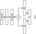
- Fig. 3 shows an embodiment of a method for identifying a device behind which an impairment of a network is caused.
- a street amplifier device 5 suffering from a partial or complete outage may be identified, wherein the house amplifier device 4b is connected to the street amplifier device 5.
- Identification of the street amplifier device can be performed by means of conventional network monitoring software.
- a switch-off signal is transmitted from the control device 2 to a switching device 3, wherein the switching device 3 is connected upstream a house amplifier device 4b behind which an impairment of the network 1 is suspected to be caused.
- the switching device 3 identifies whether the control device 2 is permitted to transmit at least one of the switch-off signal and the switch-on signal by checking a caller identification and/or a security code comprised in the respective signal. Without a proper authorization, the switching device 3 will simply disregard the received command.
- the control device 2 is able to determine in step S4 whether the impairment of the network 1 still exists. This may be done by means of the conventional network monitoring software. In case the impairment of the network 1 does not exist anymore, the house amplifier device 4b is identified in step S5a as the device behind which the impairment of the network 1 is caused. Alternatively, in case the impairment of the network 1 still exists, the house amplifier device 4b is identified in step S5b as a device behind which the impairment of the network 1 is not caused.
- control device 2 transmits a switch-on signal from the control device 2 to the switching device 3 in step S6. If a house amplifier device is identified not to be the device behind which the impairment of the network 1 is caused, the above method steps are continued with further house amplifier devices, e.g. in the same street, until the "correct" house amplifier device is found. Since the overall process takes less than one minute per house amplifier device, it is possible to identify the cause of a problem quickly. For example, if a fibre node/hub 8 serves 120 houses/house amplifiers, a problem identification can be done in less than two hours.
- Fig. 4 shows an embodiment of a system 6 for identifying a device behind which an impairment of a network 1 is caused.
- the system 6 comprises a control device 2 that is configured to transmit a switch-off signal to a switching device 3, wherein the switching device 3 is connected upstream a house amplifier device 4b behind which an impairment of the network 1 is suspected to be caused.
- the switch-off signal is transmitted using a Short Message Service (SMS).
- SMS Short Message Service
- the switching device 3 After the switch-off signal is received by the switching device 3, it turns of a power supply of the house amplifier device 4b. Prior to turning off the power supply, the switching device 3 may check whether the control device 2 is authorized to instruct the switching device 3 to do so, for example by checking a caller identification and/or a security code comprised in the respective signal.
- the control device 2 is further configured to determine whether the impairment of the network still exists, wherein in case the impairment of the network 1 does not exist anymore, the control device 2 is configured to identify the house amplifier device 4b as the device behind which the impairment of the network 1 is caused and, in case the impairment of the network 1 still exists, the control device 2 is configured to identify the house amplifier device 4b as a device which the impairment of the network 1 is not caused.
- control device 2 transmits a switch-on signal to the switching device 3, based upon which the switching device 3 turns on the power supply of the house amplifier device 4b again.
Landscapes
- Engineering & Computer Science (AREA)
- Signal Processing (AREA)
- Multimedia (AREA)
- Computer Networks & Wireless Communication (AREA)
- Computer Security & Cryptography (AREA)
- Alarm Systems (AREA)
Abstract
Description
- The present application proposes a method and a system for identifying a device behind which an impairment of a network is caused. Furthermore, a corresponding control device and a corresponding switching device are proposed.
- At present, finding the source of bad internet or complete outage of internet in cable networks is quite difficult. This is the case because a cable network works on coaxial cables that are notorious for being easy to break, crack and fragile. These cables are hidden underground usually outside and hence, quite safe. However, in customers' houses, said cables are exposed and - when connected to modems and splitters -most vulnerable. A simple loose connection in a customer's house or a dog bite can cause a huge problem in the cable network until the hub/fibre node. In private houses, about 90% of reported issues are caused by this factor.
- The prior art provides several tools that allow to detect on street level that a certain street is causing a semi or full network outage. However, a street usually comprises hundreds of households and, according to current approaches, a technical expert must go from door to door in order to investigate the issue for the outage manually. Besides the fact that the technician might meet unhappy residents or might even miss residents, the technician has to perform a lot of trips to solve the issue. Further, it might be even the case that the issue is considered solved but due to lack of a proper localization of the issue, issues tend to repeat and such increases time to resolve the same, thus decreasing customer satisfaction.
- In view of this, the technical problem can be seen to be that of providing a solution that allows to faster pin-point a troublemaker house without requiring troublesome field work for a technician. The solution should be simple, low-cost, and reliable.
- In order to solve this problem, a method for identifying a device behind which an impairment of a network is caused is proposed, the method comprising: transmitting a switch-off signal from a control device to a switching device, wherein the switching device is connected upstream a house amplifier device behind which an impairment of the network is suspected to be caused; determining, by the control device, whether the impairment of the network still exists; in case the impairment of the network does not exist anymore, identifying the house amplifier device as the device behind which the impairment of the network is caused; in case the impairment of the network still exists, identifying the house amplifier device as a device which the impairment of the network is not caused; and transmitting a switch-on signal from the control device to the switching device.
- With this approach, it is possible to easily localize a house causing network issues. Although an issue ultimately has to be still solved by a technician on-site, it is not required anymore for the technician to go from house to house since the switching device serves as a fixed part of the network. On the contrary, solutions known from the prior art such as analyzing modem pings, analyzing ticket histories or using artificial intelligence (AI) cannot reach an accurate solution since it is not possible to account for unpredictable things that may happen in households. For example, children playing and damaging network elements cannot be predicted because the AI solutions do not have daily intricate information and/or data about the customers' behaviour. These types of issues are not recognizable via modem pings either because once the issue appears, the modems are already compromised because of Return Path Impairment (RPI) or a full outage is causing loss of connection.
- However, the proposed solution may work with a GSM network and thus may be completely detached from the cable network itself and hence, even if a relevant part of the cable network is down, the switching device can still be reached. Moreover, in places with poor GSM network coverage at the installation site of the switching device, e.g. in basements, it is possible to simply attach an external antenna to the switching device to increase GSM network coverage. Since the switching device is only controlled with two different commands, said device does not need a constant connection and does not generate network traffic like other devices that work e.g. on 3G, 4G, or 5G communication networks, which require constant connection and - at times - also a restart.
- According to an aspect, the network is at least a part of a cable network providing at least one of a telephone service, an internet service, and a television service. According to another aspect, the method comprises identifying a street amplifier device suffering from a partial or complete outage, wherein the house amplifier device is connected to the street amplifier device. This is particularly advantageous since transmitting the switch-off signal can be subsequently transmitted only to house amplifier devices that belong to houses of a street or area, for which an issue has been encountered.
- According to yet another aspect, at least one of the switch-off signal and the switch-on signal is transmitted using a Short Message Service (SMS). This has the advantage that the established 2G/GSM communication standard can be used, which will not be discounted in the foreseeable future.
- Moreover, the method may further comprise identifying, by the switching device, whether the control device is permitted to transmit at least one of the switch-off signal and the switch-on signal by checking a caller identification and/or a security code comprised in the respective signal. This increases overall security because other devices are hindered from controlling the switching device.
- According to another aspect of the present invention it is suggested to use a pool testing approach, especially in case there is a huge number of possible houses on a street level with one or more of them being the house causing outage, whereby a switch-off signal is sent to a set of houses simultaneously, e.g. 60 houses simultaneously, and whereby it is checked whether the impairment of the network vanishes/disappears. If this is the case, one or more house of these set of houses causes the impairment and is identified as a target for further analysis. Otherwise, a switch-off signal is sent to another set of houses and the same determination is performed. Hence, it is possible to decrease the number of targets from e.g. 120 to 60 in a couple of minutes. After this, the number of potential houses can be reduced e.g. from 60 to 30 in the same manner and the step can be repeated likewise. Thus, in e.g. three more minutes, the number of houses can be brought down to 15 and 7 respectively. This approach is even faster than sending a switch-off signal to a plurality of houses sequentially. However, if e.g. only ten houses or less are connected to a
street amplifier device 5, the sequential approach may be more advantageous. - According to another embodiment, a system for identifying a device behind which an impairment of a network is caused is provided, the system comprising: a control device configured to transmit a switch-off signal from a control device to a switching device, wherein the switching device is connected upstream a house amplifier device behind which an impairment of the network is suspected to be caused; determine whether the impairment of the network still exists; in case the impairment of the network does not exist anymore, identify the house amplifier device as the device behind which the impairment of the network is caused; in case the impairment of the network still exists, identify the house amplifier device as a device which the impairment of the network is not caused; transmit a switch-on signal from the control device to the switching device; and the switching device configured to receive the switch-off signal from the control device; receive the switch-on signal from the control device.
- Advantageously, the network is a cable network providing at least one of a telephone service, an internet service, and a television service.
- According to a preferred embodiment, the control device is further configured to identify a street amplifier device suffering from a partial or complete outage, wherein the house amplifier device is connected to the street amplifier device.
- The control device may be further configured to transmit at least one of the switch-off signal and the switch-on signal using a Short Message Service (SMS).
- According to another aspect, the switching device is further configured to identify whether the control device is permitted to transmit at least one of the switch-off signal and the switch-on signal by checking a caller identification and/or a security code comprised in the respective signal.
- According to another embodiment, a control device for identifying a device behind which an impairment of a network is caused is provided, wherein the control device is configured to: transmit a switch-off signal from a control device to a switching device, wherein the switching device is connected upstream a house amplifier device behind which an impairment of the network is suspected to be caused; determine whether the impairment of the network still exists; in case the impairment of the network does not exist anymore, identify the house amplifier device as the device behind which the impairment of the network is caused; in case the impairment of the network still exists, identify the house amplifier device as a device which the impairment of the network is not caused; and transmit a switch-on signal from the control device to the switching device
- The control device may be further configured to identify a street amplifier device suffering from a partial or complete outage, wherein the house amplifier device is connected to the street amplifier device.
- According to another embodiment, a switching device, which is connected upstream a house amplifier device behind which an impairment of a network is suspected to be caused is provided, wherein the switching device is configured to receive a switch-off signal from a control device, and receive a switch-on signal from the control device.
- The switching device may be further configured to identify that a power supply for the switching device is interrupted, and send, to the control device, a notification that the power supply is interrupted.
- Advantageously, the switching device may be further configured to temporarily provide, from an energy storage of the switching device, particularly a condenser, power to enable the sending of the notification.
- Further details, features and advantages of the invention are explained in more detail below with reference to the embodiments shown in the figures of the drawings.
- Therein:
- Fig. 1
- shows an abstraction of a cable network infrastructure;
- Fig. 2
- shows a house in which a device behind which an impairment of a network is caused is located;
- Fig. 3
- shows an embodiment of a method for identifying a device behind which an impairment of a network is caused; and
- Fig. 4
- shows an embodiment of a system for identifying a device behind which an impairment of a network is caused.
-
Fig. 1 shows a cable network infrastructure in an abstracted manner. Abackbone network segment 10 is connected to at least one point ofpresence network segment 9. Likewise, said point ofpresence network segment 9 is connected to at least one fibre node/hub 8. Further, a connection from the fibre node/hub 8 is existing to at least onestreet amplifier device 5. - In case a semi or full network outage occurs caused by an issue that occurs downstream, i.e. behind, a
house amplifier device 5, the network may be impacted until fibre node/hub 8 level. Hence, an impact does not only concern users of modems that are connected to anhouse amplifier 4b behind which an impairment occurs, but also users with modems behindother house amplifiers - Throughout the embodiments, a
network 1 therefore refers to the part from a customer's modem level until fibre node/hub 8 level. - According to an embodiment, in case there is a huge number of possible houses, e.g. 120 houses, on a street level with one of them being the house causing outage, it is suggested to use a pool testing approach.
- According to such an approach, a switch-off signal is sent to e.g. 60 houses simultaneously and it is checked whether the impairment of the network vanishes/disappears. If this is the case, one of these 60 houses causes the impairment and is identified as a target for further analysis. Otherwise, a switch-off signal is sent to the other 60 houses and the same determination is performed. Hence, it is possible to decrease the number of targets from 120 to 60 in a couple of minutes. After this, the number of potential houses can be reduced from 60 to 30 in the same manner and the step can be repeated likewise. Thus, in e.g. three more minutes, the number of houses can be brought down to 15 and 7 respectively.
- This approach is even faster than sending a switch-off signal to a plurality of houses sequentially. However, if e.g. only ten houses or less are connected to a
street amplifier device 5, the sequential approach may be more advantageous. -
Fig. 2 shows a more detailed view of a house in which a device behind which an impairment of a network is caused is located. It is apparent fromFig. 2 that thehouse amplifier device 4b is located downstreamstreet amplifier device 5. - Furthermore, said
house amplifier device 4b serves to be connected to a plurality ofmodems Fig. 2 , the connection towardsmodem 7a is interrupted, for example due to a loose cable. - Furthermore,
Fig. 2 discloses that aswitching device 3 is connected upstream ahouse amplifier device 4b behind which an impairment of thenetwork 1 is suspected to be caused. -
Fig. 2 further shows acontrol device 2 for identifying a device behind which an impairment of anetwork 1 is caused. Saidcontrol device 2 has a wireless connection to theswitching device 3 and may control the same by sending a switch-off signal and sending a switch-on signal to the same. - By sending the switch-off signal from the
control device 2 to theswitching device 3, it can be determined whether the impairment of thenetwork 1 still exists. In detail, in case the impairment of thenetwork 1 does still exist, thecontrol device 2 identifies thehouse amplifier device 4b as the device behind which the impairment of thenetwork 1 is not caused. However, in the present case, the impairment of thenetwork 1 does not exist anymore and hence, thecontrol device 2 identifies thehouse amplifier device 4b as the device behind which the impairment of thenetwork 1 is caused. - After it has been successfully determined whether the impairment of the
network 1 still exists, thecontrol device 2 transmits a switch-on signal from thecontrol device 2 to theswitching device 3. Hence,modems house amplifier device 4b causes the problem. -
Fig. 3 shows an embodiment of a method for identifying a device behind which an impairment of a network is caused. In a first optional method step S1, astreet amplifier device 5 suffering from a partial or complete outage may be identified, wherein thehouse amplifier device 4b is connected to thestreet amplifier device 5. Identification of the street amplifier device can be performed by means of conventional network monitoring software. - Subsequently, in method step S2, a switch-off signal is transmitted from the
control device 2 to aswitching device 3, wherein theswitching device 3 is connected upstream ahouse amplifier device 4b behind which an impairment of thenetwork 1 is suspected to be caused. - According to another optional method step S3, the
switching device 3 identifies whether thecontrol device 2 is permitted to transmit at least one of the switch-off signal and the switch-on signal by checking a caller identification and/or a security code comprised in the respective signal. Without a proper authorization, theswitching device 3 will simply disregard the received command. - After that, the
control device 2 is able to determine in step S4 whether the impairment of thenetwork 1 still exists. This may be done by means of the conventional network monitoring software. In case the impairment of thenetwork 1 does not exist anymore, thehouse amplifier device 4b is identified in step S5a as the device behind which the impairment of thenetwork 1 is caused. Alternatively, in case the impairment of thenetwork 1 still exists, thehouse amplifier device 4b is identified in step S5b as a device behind which the impairment of thenetwork 1 is not caused. - Finally, the
control device 2 transmits a switch-on signal from thecontrol device 2 to theswitching device 3 in step S6. If a house amplifier device is identified not to be the device behind which the impairment of thenetwork 1 is caused, the above method steps are continued with further house amplifier devices, e.g. in the same street, until the "correct" house amplifier device is found. Since the overall process takes less than one minute per house amplifier device, it is possible to identify the cause of a problem quickly. For example, if a fibre node/hub 8 serves 120 houses/house amplifiers, a problem identification can be done in less than two hours. -
Fig. 4 shows an embodiment of asystem 6 for identifying a device behind which an impairment of anetwork 1 is caused. - The
system 6 comprises acontrol device 2 that is configured to transmit a switch-off signal to aswitching device 3, wherein theswitching device 3 is connected upstream ahouse amplifier device 4b behind which an impairment of thenetwork 1 is suspected to be caused. In the present case, the switch-off signal is transmitted using a Short Message Service (SMS). - After the switch-off signal is received by the
switching device 3, it turns of a power supply of thehouse amplifier device 4b. Prior to turning off the power supply, theswitching device 3 may check whether thecontrol device 2 is authorized to instruct theswitching device 3 to do so, for example by checking a caller identification and/or a security code comprised in the respective signal. - The
control device 2 is further configured to determine whether the impairment of the network still exists, wherein in case the impairment of thenetwork 1 does not exist anymore, thecontrol device 2 is configured to identify thehouse amplifier device 4b as the device behind which the impairment of thenetwork 1 is caused and, in case the impairment of thenetwork 1 still exists, thecontrol device 2 is configured to identify thehouse amplifier device 4b as a device which the impairment of thenetwork 1 is not caused. - After that, the
control device 2 transmits a switch-on signal to theswitching device 3, based upon which theswitching device 3 turns on the power supply of thehouse amplifier device 4b again. - The embodiments shown in the figures of the drawing and the embodiments explained in connection therewith serve only to explain the invention and are not limiting for the same.
-
- 1
- Network
- 2
- Control device
- 3
- Switching device
- 4a-4c
- House amplifier device
- 5
- Street amplifier device
- 6
- System
- 7a-7c
- Modem
- 8
- Fibre node/hub
- 9
- Point of presence
- 10
- Backbone
- S1
- Method step
- S2
- Method step
- S3
- Method step
- S4
- Method step
- S5a
- Method step
- S5b
- Method step
- S6
- Method step
Claims (16)
- A method for identifying a device behind which an impairment of a network (1) is caused, comprising:transmitting (S2) a switch-off signal from a control device (2) to a switching device (3), wherein the switching device (3) is connected upstream a house amplifier device (4b) behind which an impairment of the network (1) is suspected to be caused;determining (S4), by the control device (2), whether the impairment of the network (1) still exists;in case the impairment of the network (1) does not exist anymore, identifying (S5a) the house amplifier device (4b) as the device behind which the impairment of the network (1) is caused;in case the impairment of the network (1) still exists, identifying (S5b) the house amplifier device (4b) as a device behind which the impairment of the network (1) is not caused; andtransmitting (S6) a switch-on signal from the control device (2) to the switching device (3).
- The method of claim 1, wherein the network (1) is at least a part of a cable network providing at least one of a telephone service, an internet service, and a television service.
- The method of claim 1 or claim 2, further comprising:identifying (S1) a street amplifier device (5) suffering from a partial orcomplete outage, wherein the house amplifier device (4b) is connected to the street amplifier device (5).
- The method of any one of claims 1 to 3, wherein at least one of the switch-off signal and the switch-on signal is transmitted using a Short Message Service, SMS.
- The method of any one of claims 1 to 4, further comprising:identifying (S3), by the switching device (3), whether the control device is permitted to transmit at least one of the switch-off signal and the switch-on signal by checking a caller identification and/or a security code comprised in the respective signal.
- A method according to any one of claims 1 to 5, wherein a switch-off signal is sent to a set of houses simultaneously and whereby it is checked whether the impairment of the network vanishes/disappears, whereby in the case the impairment of the network vanishes/disappears one or more houses of these set of houses causes the impairment and is identified as a target for further analysis, otherwise, a switch-off signal is sent to another set of houses and the same determination is performed.
- A system (6) for identifying a device behind which an impairment of a network (1) is caused, comprising:a control device (2) configured totransmit (S2) a switch-off signal from a control device (2) to a switching device (3), wherein the switching device (3) is connected upstream a house amplifier device (4b) behind which an impairment of the network (1) is suspected to be caused;determine (S4) whether the impairment of the network (1) still exists;in case the impairment of the network (1) does not exist anymore, identify (S5a) the house amplifier device (4b) as the device behind which the impairment of the network (1) is caused;in case the impairment of the network (1) still exists, identify (S5b) the house amplifier device (4b) as a device which the impairment of the network (1) is not caused;transmit (S6) a switch-on signal from the control device (2) to the switching device (3); and
the switching device (3) configured toreceive (S2) the switch-off signal from the control device (2);receive (S6) the switch-on signal from the control device (2). - The system (6) of claim 7, wherein the network (1) is a cable network providing at least one of a telephone service, an internet service, and a television service.
- The system (6) of claim 7 or claim 8, wherein the control device (2) is further configured to:
identify (S1) a street amplifier device suffering from a partial or complete outage, wherein the house amplifier device behind which an impairment of the network (1) is suspected to be caused building is connected to the street amplifier device. - The system (6) of any one of claims 7 to 9, wherein the control device (2) is configured to transmit at least one of the switch-off signal and the switch-on signal using a Short Message Service, SMS.
- The system (6) of any one of claims 7 to 10, wherein the switching device (3) is further configured to:
identify (S3) whether the control device (2) is permitted to transmit at least one of the switch-off signal and the switch-on signal by checking a caller identification and/or a security code comprised in the respective signal. - A control device (2) for identifying a device behind which an impairment of a network (1) is caused configured to:transmit a switch-off signal from a control device (2) to a switching device (3), wherein the switching device (3) is connected upstream a house amplifier device (4b) behind which an impairment of the network (1) is suspected to be caused;determine whether the impairment of the network (1) still exists;in case the impairment of the network (1) does not exist anymore, identify the house amplifier device (4b) as the device behind which the impairment of the network (1) is caused;in case the impairment of the network (1) still exists, identify the house amplifier device (4b) as a device which the impairment of the network (1) is not caused; andtransmit a switch-on signal from the control device (2) to the switching device (3).
- The control device (2) of claim 12, further configured to:identify a street amplifier device suffering from a partial or complete outage,wherein the house amplifier device (4b) is connected to the street amplifier device.
- A switching device (3), which is connected upstream a house amplifier device (4b) behind which an impairment of the network (1) is suspected to be caused, configured to:receive a switch-off signal from a control device (2); andreceive a switch-on signal from the control device (2).
- The switching device (3) of claim 14, further configured to:identify that a power supply for the switching device (3) is interrupted; andsend, to the control device (2), a notification that the power supply is interrupted.
- The switching device (3) of claim 15, further configured to:temporarily provide, from an energy storage of the switching device (3),particularly a condenser, power to enable the sending of the notification.
Priority Applications (1)
| Application Number | Priority Date | Filing Date | Title |
|---|---|---|---|
| EP21196007.5A EP4149076A1 (en) | 2021-09-10 | 2021-09-10 | Identification of a device behind which an impairment of a network is caused |
Applications Claiming Priority (1)
| Application Number | Priority Date | Filing Date | Title |
|---|---|---|---|
| EP21196007.5A EP4149076A1 (en) | 2021-09-10 | 2021-09-10 | Identification of a device behind which an impairment of a network is caused |
Publications (1)
| Publication Number | Publication Date |
|---|---|
| EP4149076A1 true EP4149076A1 (en) | 2023-03-15 |
Family
ID=78008071
Family Applications (1)
| Application Number | Title | Priority Date | Filing Date |
|---|---|---|---|
| EP21196007.5A Pending EP4149076A1 (en) | 2021-09-10 | 2021-09-10 | Identification of a device behind which an impairment of a network is caused |
Country Status (1)
| Country | Link |
|---|---|
| EP (1) | EP4149076A1 (en) |
Citations (3)
| Publication number | Priority date | Publication date | Assignee | Title |
|---|---|---|---|---|
| EP1257089A2 (en) * | 2001-05-08 | 2002-11-13 | AT&T Corp. | Method and system for generating geographic visual displays of broadband network data |
| US20070169162A1 (en) * | 2006-01-18 | 2007-07-19 | Srinivas Kola | Hierarchical communications network with upstream signal controllable from head end |
| US20080320541A1 (en) * | 2007-06-19 | 2008-12-25 | Zinevich Victor M | Method and apparatus for locating network impairments |
-
2021
- 2021-09-10 EP EP21196007.5A patent/EP4149076A1/en active Pending
Patent Citations (3)
| Publication number | Priority date | Publication date | Assignee | Title |
|---|---|---|---|---|
| EP1257089A2 (en) * | 2001-05-08 | 2002-11-13 | AT&T Corp. | Method and system for generating geographic visual displays of broadband network data |
| US20070169162A1 (en) * | 2006-01-18 | 2007-07-19 | Srinivas Kola | Hierarchical communications network with upstream signal controllable from head end |
| US20080320541A1 (en) * | 2007-06-19 | 2008-12-25 | Zinevich Victor M | Method and apparatus for locating network impairments |
Non-Patent Citations (1)
| Title |
|---|
| PAING SOE ET AL: "Sms-Based Home Management System", INTERNATIONAL JOURNAL OF SCIENTIFIC & TECHNOLOGY RESEARCH, 1 January 2016 (2016-01-01), pages 88 - 91, XP055885439, Retrieved from the Internet <URL:https://www.ijstr.org/final-print/june2016/Sms-based-Home-Management-System.pdf> [retrieved on 20220131] * |
Similar Documents
| Publication | Publication Date | Title |
|---|---|---|
| US7424527B2 (en) | System and method for transmitting pollution information over an integrated wireless network | |
| CA2602289C (en) | Using a fixed network wireless data collection system to improve utility responsiveness to power outages | |
| US12431991B2 (en) | Antenna and environmental conditions monitoring for wireless and telecommunications for private, public, first responders, and emergency responder radio communication system (ERRCS) | |
| US7576646B2 (en) | Method and apparatus for adding wireless devices to a security system | |
| US20090184816A1 (en) | Alarm system walk test | |
| CN102625230A (en) | Building system communication method, apparatus and system thereof | |
| US10594412B2 (en) | Antenna monitoring for wireless and telecommunications for private, public, and first responders | |
| JP5907734B2 (en) | Cooperation system | |
| KR100984674B1 (en) | Method and system for managing self diagnosable p-type control panels | |
| AU2018255494B2 (en) | Emergency lighting system | |
| KR100979179B1 (en) | Method and system for managing self diagnosable p-type control panels | |
| US11417201B2 (en) | System and method for entry check-in protection | |
| US20050104723A1 (en) | Method for monitoring a parking lot with meters and corresponding parking meters | |
| KR101779050B1 (en) | Apparatus and method for repeater control | |
| KR102481233B1 (en) | Method for transmitting data between terminals and access point based on LoRa wireless communication technology | |
| KR101588603B1 (en) | Security features provided with a mobile two-way text sending and receiving system | |
| KR101036628B1 (en) | Home-use repeater with surveillance device and surveillance method | |
| KR100778297B1 (en) | Wireless communication system | |
| KR20010008240A (en) | CDMA Repeater Guard System by N:1 Muliple Connecting Method | |
| KR101304435B1 (en) | Repeater remote monitoring system | |
| KR20060074957A (en) | Unmanned security system and its operation method | |
| KR20250081572A (en) | System for maintaining a roadside equipment | |
| KR100545290B1 (en) | Integrated management method of base station and repeater for network failure determination | |
| KR19980084844A (en) | Data Transceiver and Data Transceiver System using CT-2 NET |
Legal Events
| Date | Code | Title | Description |
|---|---|---|---|
| PUAI | Public reference made under article 153(3) epc to a published international application that has entered the european phase |
Free format text: ORIGINAL CODE: 0009012 |
|
| STAA | Information on the status of an ep patent application or granted ep patent |
Free format text: STATUS: THE APPLICATION HAS BEEN PUBLISHED |
|
| AK | Designated contracting states |
Kind code of ref document: A1 Designated state(s): AL AT BE BG CH CY CZ DE DK EE ES FI FR GB GR HR HU IE IS IT LI LT LU LV MC MK MT NL NO PL PT RO RS SE SI SK SM TR |
|
| STAA | Information on the status of an ep patent application or granted ep patent |
Free format text: STATUS: REQUEST FOR EXAMINATION WAS MADE |
|
| 17P | Request for examination filed |
Effective date: 20230615 |
|
| RBV | Designated contracting states (corrected) |
Designated state(s): AL AT BE BG CH CY CZ DE DK EE ES FI FR GB GR HR HU IE IS IT LI LT LU LV MC MK MT NL NO PL PT RO RS SE SI SK SM TR |
|
| STAA | Information on the status of an ep patent application or granted ep patent |
Free format text: STATUS: EXAMINATION IS IN PROGRESS |
|
| 17Q | First examination report despatched |
Effective date: 20241031 |
|
| RIN1 | Information on inventor provided before grant (corrected) |
Inventor name: HELLWEG, PATRICK Inventor name: BOSSEMS, CHRISTOPH Inventor name: FAYYAZ, MUNEEB |