EP4149028A1 - Synchronization for backplane communication - Google Patents
Synchronization for backplane communication Download PDFInfo
- Publication number
- EP4149028A1 EP4149028A1 EP21306240.9A EP21306240A EP4149028A1 EP 4149028 A1 EP4149028 A1 EP 4149028A1 EP 21306240 A EP21306240 A EP 21306240A EP 4149028 A1 EP4149028 A1 EP 4149028A1
- Authority
- EP
- European Patent Office
- Prior art keywords
- primary
- control module
- communication line
- timestamp
- clock
- Prior art date
- Legal status (The legal status is an assumption and is not a legal conclusion. Google has not performed a legal analysis and makes no representation as to the accuracy of the status listed.)
- Granted
Links
Images

Classifications
-
- H—ELECTRICITY
- H04—ELECTRIC COMMUNICATION TECHNIQUE
- H04J—MULTIPLEX COMMUNICATION
- H04J3/00—Time-division multiplex systems
- H04J3/02—Details
- H04J3/06—Synchronising arrangements
- H04J3/0635—Clock or time synchronisation in a network
- H04J3/0638—Clock or time synchronisation among nodes; Internode synchronisation
- H04J3/0647—Synchronisation among TDM nodes
- H04J3/065—Synchronisation among TDM nodes using timestamps
-
- H—ELECTRICITY
- H04—ELECTRIC COMMUNICATION TECHNIQUE
- H04J—MULTIPLEX COMMUNICATION
- H04J3/00—Time-division multiplex systems
- H04J3/02—Details
- H04J3/06—Synchronising arrangements
- H04J3/0635—Clock or time synchronisation in a network
- H04J3/0638—Clock or time synchronisation among nodes; Internode synchronisation
- H04J3/0652—Synchronisation among time division multiple access [TDMA] nodes, e.g. time triggered protocol [TTP]
- H04J3/0655—Synchronisation among time division multiple access [TDMA] nodes, e.g. time triggered protocol [TTP] using timestamps
-
- H—ELECTRICITY
- H04—ELECTRIC COMMUNICATION TECHNIQUE
- H04J—MULTIPLEX COMMUNICATION
- H04J3/00—Time-division multiplex systems
- H04J3/02—Details
- H04J3/06—Synchronising arrangements
- H04J3/0635—Clock or time synchronisation in a network
- H04J3/0638—Clock or time synchronisation among nodes; Internode synchronisation
- H04J3/0658—Clock or time synchronisation among packet nodes
- H04J3/0661—Clock or time synchronisation among packet nodes using timestamps
- H04J3/0667—Bidirectional timestamps, e.g. NTP or PTP for compensation of clock drift and for compensation of propagation delays
-
- H—ELECTRICITY
- H04—ELECTRIC COMMUNICATION TECHNIQUE
- H04J—MULTIPLEX COMMUNICATION
- H04J3/00—Time-division multiplex systems
- H04J3/02—Details
- H04J3/06—Synchronising arrangements
- H04J3/0635—Clock or time synchronisation in a network
- H04J3/0685—Clock or time synchronisation in a node; Intranode synchronisation
-
- H—ELECTRICITY
- H04—ELECTRIC COMMUNICATION TECHNIQUE
- H04L—TRANSMISSION OF DIGITAL INFORMATION, e.g. TELEGRAPHIC COMMUNICATION
- H04L12/00—Data switching networks
- H04L12/28—Data switching networks characterised by path configuration, e.g. LAN [Local Area Networks] or WAN [Wide Area Networks]
- H04L12/40—Bus networks
- H04L12/403—Bus networks with centralised control, e.g. polling
- H04L12/4035—Bus networks with centralised control, e.g. polling in which slots of a TDMA packet structure are assigned based on a contention resolution carried out at a master unit
-
- H—ELECTRICITY
- H04—ELECTRIC COMMUNICATION TECHNIQUE
- H04L—TRANSMISSION OF DIGITAL INFORMATION, e.g. TELEGRAPHIC COMMUNICATION
- H04L49/00—Packet switching elements
- H04L49/35—Switches specially adapted for specific applications
- H04L49/354—Switches specially adapted for specific applications for supporting virtual local area networks [VLAN]
-
- H—ELECTRICITY
- H04—ELECTRIC COMMUNICATION TECHNIQUE
- H04L—TRANSMISSION OF DIGITAL INFORMATION, e.g. TELEGRAPHIC COMMUNICATION
- H04L12/00—Data switching networks
- H04L12/28—Data switching networks characterised by path configuration, e.g. LAN [Local Area Networks] or WAN [Wide Area Networks]
- H04L12/46—Interconnection of networks
-
- H—ELECTRICITY
- H04—ELECTRIC COMMUNICATION TECHNIQUE
- H04L—TRANSMISSION OF DIGITAL INFORMATION, e.g. TELEGRAPHIC COMMUNICATION
- H04L12/00—Data switching networks
- H04L12/28—Data switching networks characterised by path configuration, e.g. LAN [Local Area Networks] or WAN [Wide Area Networks]
- H04L12/40—Bus networks
- H04L2012/4026—Bus for use in automation systems
Definitions
- the present disclosure relates generally to industrial networks and, more particularly, to systems that support multiple industrial Ethernet protocols, fieldbus protocols, and industrial application processing, and provide high performance for backplane communication for programmable logic controller in industrial architecture.
- Industrial automation/control systems are employed for controlling operation of a wide variety of systems, including processes, machines, etc., and are typically adaptable to different control applications through configuration and interconnection of multiple control system components or devices, such as control modules, Input/Output (I/O) modules, I/O devices, etc.
- existing industrial control systems typically include a processor running or executing a control program to interact with an I/O system (e.g., typically one or more I/O modules or devices) to receive system information in the form of analog and/or digital inputs from field sensors and to provide outputs (analog and/or digital) to one or more actuators.
- Industrial control systems are increasingly being interconnected with management information and other systems in a manufacturing facility, and may be operatively connected to any number of communications networks to facilitate various business management functions such as inventory control, accounting, manufacturing control, etc., in addition to the process/machine control functionality.
- Industrial Ethernet networks e.g., such as Ethernet/IP networks that allow for direct connection of field devices to an Ethernet network
- a standalone I/O island is connected to a control device like a programmable logic controller PLC with a fieldbus like Ethernet/IP and contains a head driving clusters of I/O modules respectively through cluster managers.
- a cluster is a set of I/O modules, up to 32 modules, physically linked together through a backplane and an I/O module is a usual automation module converting electrical signals to digital values.
- the cluster manager and different modules can communicate by means of their respective switches through a multipoint communication line.
- a port of a switch may be configured to send a specific frame at a schedule time window, especially if the switches share a same clock and are synchronized.
- the heads and the cluster managers can be synchronized using a Generalized Precision Time Protocol (gPTP) which employs layer 2 (Ethernet) messages to establish a hierarchy of clocks and synchronize time in a gPTP domain which the heads and the cluster managers belong to.
- gPTP Generalized Precision Time Protocol
- Ethernet layer 2
- the I/O modules cannot transmit before being synchronized and a standard stack in a switch of a I/O module needs to transmit before starting the synchronization algorithm.
- an industrial system for controlling backplane communication comprising:
- the industrial system allows the I/O modules to be synchronized with the cluster manager without involving a switch nor a hub and enables the communication between I/O modules and the cluster manager while respecting real time constraint and low-cost products by the use of passive base plates and the unidirectional communication line.
- the use of the unidirectional communication line in passive base plates allows a high level of reliability with no active component in the backplane and minimized risk of failure and offers a low-cost solution as no external switch is needed.
- the mechanism related to a path delay is eliminated by means of the pulse received at the same time by the cluster manager and the I/O modules via the unidirectional communication line.
- the path delay is considered null or negligible so its calculation can be removed from a clock servo algorithm for synchronization.
- the primary timestamp and the secondary timestamp are created simultaneously, the path delay between the reception port of the cluster manager and the reception port of the at least one Input/Output module being considered null or negligible.
- the cluster manager is further linked to the at least one IO module via a multipoint communication line allowing the cluster manager to transmit data in frames on the multipoint communication line at scheduled time windows to the at least one IO module when the primary clock and the secondary clock are synchronized.
- the primary switch and the secondary switch are Time Sensitive Networking switches.
- the primary switch and the secondary switch are implemented with the IEEE 802.1Qbv time-aware scheduler to schedule static time windows and dynamic time windows.
- the primary clock and the secondary clock are synchronized based on Precision Time Protocol.
- the primary clock is able to be synchronized in time based on a Generalized Precision Time Protocol in a time domain which other cluster managers belong to.
- the message further comprises an error-detecting code to determine if the message contains errors.
- a method for controlling backplane communication of an industrial system that comprises:
- a computer-readable medium having embodied thereon a computer program for executing a method for controlling backplane communication of an industrial system.
- Said computer program comprises instructions which carry out steps according to the method according to the invention.
- TSN time sensitive network
- IEEE 802.1 time sensitive network has emerged as a popular technology.
- TSN refers to the IEEE 802.1Q defined standard technology to provide deterministic messaging on standard Ethernet.
- TSN is a Layer 2 technology and is centrally managed and delivers guarantees of delivery and minimized jitter using time scheduling for those real-time applications that require determinism.
- TSN is an Ethernet standard, rather than an Internet Protocol (IP) standard.
- IP Internet Protocol
- the forwarding decisions made by the TSN bridges use the Ethernet header contents, not the IP address.
- the payloads of the Ethernet frames can be anything and are not limited to IP. This means that TSN can be used in any environment and can carry the payload of any industrial application.
- an industrial communication system comprises a cluster manager CM, a set of I/O modules IOM, base plates BP and a unidirectional communication line UCL. Furthermore, the industrial communication system comprises a multipoint communication line MCL linking the cluster manager CM and the set of I/O modules IOM.
- the cluster manager CM is able to manage communication with a set of I/O modules IOM, up to 32, via the multipoint communication line like a multipoint low voltage differential signaling (MLVDS) bus, and optionally with another cluster manager via Ethernet and CAN (Controller Area Network) bus.
- the cluster manager CM is driven by a head that can drive other cluster managers.
- the cluster manager is included in the head connected via a fieldbus to a control device like a PLC.
- the head is also included in the PLC.
- An I/O module IOM can include Analog to Digital Converter (ADC) and Digital to Analog Converter (DAC) for connecting to sensors and the real world, communications modules, digital inputs and outputs, relays, and more.
- ADC Analog to Digital Converter
- DAC Digital to Analog Converter
- An I/O module communicates with the control manager CM through the communication bus with adapted packet formats.
- the base plates BP are respectively associated with the I/O modules that are plugged into them.
- the base plates BP may be designed to form a backplane for the set of I/O modules, each combination of base plate and associated I/O module forming a slice of the backplane.
- Each base plate is a passive base plate that offers no active bus driving circuitry, any desired arbitration logic being placed on the I/O module.
- a passive base plate is thus expected to not have a single point of failure (SPOF).
- the unidirectional communication line UCL is a physical medium configured to be coupled to multiple I/O modules and the cluster manager and provides a multi-drop capability from the cluster manager. More precisely, the cluster manager comprises a transmission port TPC and a reception port RPC on the unidirectional communication line and each Input/Output module comprises a reception port RPM on the unidirectional communication line.
- the unidirectional communication line is a signaling line allowing the cluster manager to send data that are received simultaneously by the cluster manager itself and the I/O modules, assuming the propagation time in the unidirectional communication line is negligible.
- the cluster manager CM comprises a primary switch PS and a primary control module PCM.
- the primary control module PCM controls the transmission port and the reception port on the unidirectional communication line, in order to transmit and receive data on this latter.
- An Input/Output module IOM comprises a secondary switch SS and a secondary control module SCM.
- the secondary control module SCM controls the reception port on the unidirectional communication line, in order to receive data on this latter.
- the primary switch PS and the secondary switch SS are defined as TSN switches which allow a communication between the cluster manager and an I/O module without any collision in the data traffic.
- TSN is a technology that is focused on time, and was developed to provide a way to make sure information can travel from point A to point B in a fixed and predictable amount of time.
- the primary switch PS and the secondary switch SS implement respectively a primary clock and a secondary clock.
- the primary switch PS is a time-aware relay and implements for example the standard 802.1 AS-Rev, and can be synchronized in time in a gPTP domain which heads and other cluster managers belong to.
- the primary switch PS is able to run a gPTP stack in slave mode in the gPTP domain and is able to run a PTP stack, called sPTP, in master mode in a time domain, called sPTP domain, which the cluster manager and the I/O modules belong to.
- a sPTP domain can be created for each cluster of I/O modules.
- the primary switch PS is configured to use the unidirectional communication line UCL to send a pulse that triggers a timestamp in any elements (I/O modules) of the backplane in order to synchronize the primary clock with the secondary clocks of the I/O modules.
- the unidirectional communication line is used to transport the time of the primary clock to all I/O modules.
- the secondary switch SS is able to run a sPTP stack in slave mode in order to be synchronized with the primary switch PS running a sPTP stack in master mode that can be updated in the gPTP domain.
- all the elements of a whole industrial system can be updated and synchronized in time: in the gPTP domain encompassing a northbound network and synchronizing all the cluster managers with heads, and in the sPTP domain encompassing a southbound network in each cluster of I/O modules and synchronizing all the I/O modules managers with their respective cluster manager.
- the primary control module PCM is able to generate a periodic pulse via the transmission port on the unidirectional communication line.
- the pulse is then received on the reception port RPC of the cluster manager and the reception port RPM of each I/O module.
- the primary control module PCM Upon reception of the pulse, the primary control module PCM is able to create a primary timestamp from the primary clock of the primary switch and each secondary control module SCM is configured to create a secondary timestamp from the secondary clock of the corresponding secondary switch.
- the primary control module PCM transmits a message via the transmission port on the unidirectional communication line, the message being received by all I/O modules linked to the unidirectional communication line and comprising the primary timestamp.
- the message can further comprise an error-detecting code like a cyclic redundancy check (CRC) to determine if the message containing the primary timestamp contains errors or has been corrupted.
- CRC cyclic redundancy check
- each I/O module Upon reception of the message, each I/O module is able to synchronize the secondary clock with the primary clock based on the received primary timestamp and the previously created secondary timestamp.
- this mechanism allows the synchronization of the secondary clock with the primary clock and removes the delay from the line: delay measurement and compensation are not needed anymore in comparison with a classic PTP event message sequences that occur during synchronization.
- the cluster manager CM is thus synchronized in time with the set of I/O modules and is able to communicate with the set of I/O modules via the multipoint communication line MCL.
- the cluster manager CM further contains a packet processor that manages the data frames, like Ethernet frames, coming from the I/O modules through the primary switch PS via the multipoint communication line MCL.
- the packet processor is able to extract the payload of each Ethernet frame, verify the signature of each payload, concatenate all payloads in one payload in only one concatenated Ethernet frame, calculate a new signature and send the concatenated Ethernet frame to a processing unit.
- the primary switch and the secondary switch define which ports are configured to send or received data.
- a port of the switch may be configured to send a specific frame at a schedule time window.
- a switch manages different traffic queues according to the concept of Time-Aware Shaping (TAS) introduced by IEEE 802.1Qbv standard.
- Time-Aware Shaping enables determinism by dividing traffic in different preconfigured time-slots configured in a Gate-Control-Lists (GCL).
- GCL Gate-Control-Lists
- the time aware shaper consists different traffic queues. Each queue is associated with a gate and has a transmission selection algorithm which selects the next packet transmitted from the queue. The queue can be organized in first in first out (FIFO).
- the state of a gate can either be open or close, and only open gates can transmit packets.
- a time aware gate opens and closes according to its configured time.
- the schedule of the gate states is specified in the GCL.
- Each entry of the list consists of a set of gate states and their duration.
- the switch commands the opening of a gate for a scheduled time window for transmitting the data in the queue associated with said gate, the other gates remaining closed.
- a switch may send data in a static time window, control data in another static time window, and potentially service data in a dynamic time window that is scheduled by the cluster manager.
- all the I/O modules can share the multipoint communication line MCL to transmit I/O data at respective scheduled static time windows with deterministic latency at each time cycle.
- the IEEE 802.1Qbv time-aware scheduler at least one I/O module can transmit service data on the communication bus at a scheduled dynamic time windows in a best effort way.
- a method for controlling backplane communication comprises steps S1 to S4.
- step S1 the primary control module PCM generates a pulse via the transmission port TPC on the unidirectional communication line UCL.
- the pulse is received by each I/O module on its reception port RPM and by the cluster manager itself on the reception port RPC.
- step S2 upon reception of the pulse, the primary control module PCM creates a primary timestamp from the primary clock of the primary switch PS. To that end, the primary control module PCM interrogates and captures the master PTP time base corresponding to the primary clock of the primary switch PS. The value of the master PTP time base captured by the primary control module PCM is sampled to create the primary timestamp.
- the secondary control module SCM creates a secondary timestamp from the secondary clock of the corresponding secondary switch SS. Similarly, the secondary control module SCM interrogates and captures the master PTP time base corresponding to the secondary clock of the secondary switch SS.
- step S3 the primary control module PCM transmits a message via the transmission port on the unidirectional communication line, the message comprising the primary timestamp and an error-detecting code.
- the message is received by each I/O module on its reception port RPM and by the cluster manager itself on the reception port RPC.
- step S4 after reception of the message, the secondary control module SCM of each I/O module is able to synchronize the secondary clock with the primary clock based on the received primary timestamp and the previously created secondary timestamp.
- the cluster manager implements two components operating the primary switch PS.
- a first component operates as described before, with the gPTP stack in slave mode and the sPTP stack in master mode.
- a second component runs only a sPTP stack in slave mode in a similar way as a secondary switch of a I/O module.
- the cluster manager after reception of the message, the cluster manager is able to synchronize an auxiliary clock with the primary clock based on the received primary timestamp and a previously created secondary timestamp by the auxiliary clock in step S2 upon reception of the pulse.
Landscapes
- Engineering & Computer Science (AREA)
- Computer Networks & Wireless Communication (AREA)
- Signal Processing (AREA)
- Synchronisation In Digital Transmission Systems (AREA)
- Communication Control (AREA)
- Information Transfer Systems (AREA)
- Small-Scale Networks (AREA)
Abstract
Description
- The present disclosure relates generally to industrial networks and, more particularly, to systems that support multiple industrial Ethernet protocols, fieldbus protocols, and industrial application processing, and provide high performance for backplane communication for programmable logic controller in industrial architecture.
- Industrial automation/control systems are employed for controlling operation of a wide variety of systems, including processes, machines, etc., and are typically adaptable to different control applications through configuration and interconnection of multiple control system components or devices, such as control modules, Input/Output (I/O) modules, I/O devices, etc. Existing industrial control systems typically include a processor running or executing a control program to interact with an I/O system (e.g., typically one or more I/O modules or devices) to receive system information in the form of analog and/or digital inputs from field sensors and to provide outputs (analog and/or digital) to one or more actuators. Industrial control systems are increasingly being interconnected with management information and other systems in a manufacturing facility, and may be operatively connected to any number of communications networks to facilitate various business management functions such as inventory control, accounting, manufacturing control, etc., in addition to the process/machine control functionality.
- A desire to integrate the business and control network structures to interconnect industrial control systems with general purpose systems, along with the evolution and development of fast Ethernet (e.g., in switch mode with full duplex capability), has allowed for Industrial Ethernet networks (e.g., such as Ethernet/IP networks that allow for direct connection of field devices to an Ethernet network) to be widely used in industrial applications. Indeed, industrial Ethernet is becoming the dominant (if not incumbent) technology in industrial automation.
- In a slice I/O architecture, a standalone I/O island is connected to a control device like a programmable logic controller PLC with a fieldbus like Ethernet/IP and contains a head driving clusters of I/O modules respectively through cluster managers. A cluster is a set of I/O modules, up to 32 modules, physically linked together through a backplane and an I/O module is a usual automation module converting electrical signals to digital values. In a cluster, the cluster manager and different modules can communicate by means of their respective switches through a multipoint communication line.
- For example, a port of a switch may be configured to send a specific frame at a schedule time window, especially if the switches share a same clock and are synchronized. The heads and the cluster managers can be synchronized using a Generalized Precision Time Protocol (gPTP) which employs layer 2 (Ethernet) messages to establish a hierarchy of clocks and synchronize time in a gPTP domain which the heads and the cluster managers belong to. For real-time communication with non-negotiable time boundaries for end-to-end transmission latencies, all switches should have a common time reference as their clocks are synchronizes among each other.
- However, the I/O modules cannot transmit before being synchronized and a standard stack in a switch of a I/O module needs to transmit before starting the synchronization algorithm.
- There is therefore a need for enabling an efficient synchronization of a cluster manager and I/O modules, the respecting reliability and real time constraints, being resistant to measurement errors.
- This summary is provided to introduce concepts related to the present inventive subject matter. This summary is not intended to identify essential features of the claimed subject matter nor is it intended for use in determining or limiting the scope of the claimed subject matter.
- In one implementation, there is provided an industrial system for controlling backplane communication, comprising:
- a cluster manager comprising a primary switch linked to a primary control module,
- at least one Input/Output, I/O, module comprising a secondary switch linked to a secondary control module,
- a unidirectional communication line linking the cluster manager to the at least one IO module through passive base plates,
- wherein the cluster manager comprises a transmission port and a reception port on the unidirectional communication line and the at least one Input/Output module comprises a reception port on the unidirectional communication line,
- wherein the primary control module is configured to generate a pulse via the transmission port on the unidirectional communication line,
- wherein, upon reception of the pulse, the primary control module is configured to create a primary timestamp from a primary clock of the primary switch and the secondary control module is configured to create a secondary timestamp from a secondary clock of the secondary switch,
- wherein the primary control module is configured to send a message via the transmission port on the unidirectional communication line to the secondary control module, the message comprising the primary timestamp,
- wherein, upon reception of the message, the secondary control module is configured to synchronize the secondary clock with the primary clock based on the received primary timestamp and secondary timestamp.
- Advantageously, the industrial system allows the I/O modules to be synchronized with the cluster manager without involving a switch nor a hub and enables the communication between I/O modules and the cluster manager while respecting real time constraint and low-cost products by the use of passive base plates and the unidirectional communication line. The use of the unidirectional communication line in passive base plates allows a high level of reliability with no active component in the backplane and minimized risk of failure and offers a low-cost solution as no external switch is needed.
- Moreover, for the synchronization, the mechanism related to a path delay is eliminated by means of the pulse received at the same time by the cluster manager and the I/O modules via the unidirectional communication line. The path delay is considered null or negligible so its calculation can be removed from a clock servo algorithm for synchronization.
- In an embodiment, the primary timestamp and the secondary timestamp are created simultaneously, the path delay between the reception port of the cluster manager and the reception port of the at least one Input/Output module being considered null or negligible.
- In an embodiment, the cluster manager is further linked to the at least one IO module via a multipoint communication line allowing the cluster manager to transmit data in frames on the multipoint communication line at scheduled time windows to the at least one IO module when the primary clock and the secondary clock are synchronized.
- In an embodiment, the primary switch and the secondary switch are Time Sensitive Networking switches.
- In an embodiment, the primary switch and the secondary switch are implemented with the IEEE 802.1Qbv time-aware scheduler to schedule static time windows and dynamic time windows.
- In an embodiment, the primary clock and the secondary clock are synchronized based on Precision Time Protocol.
- In an embodiment, the primary clock is able to be synchronized in time based on a Generalized Precision Time Protocol in a time domain which other cluster managers belong to.
- In an embodiment, the message further comprises an error-detecting code to determine if the message contains errors.
- In another implementation, there is provided a method for controlling backplane communication of an industrial system that comprises:
- a cluster manager comprising a primary switch linked to a primary control module,
- at least one Input/Output, I/O, module comprising a secondary switch linked to a secondary control module,
- a unidirectional communication line linking the cluster manager to the at least one IO module through passive base plates,
- wherein the cluster manager comprises a transmission port and a reception port on the unidirectional communication line and the at least one Input/Output module comprises a reception port on the unidirectional communication line,
- the method comprising:
- generating, by the primary control module, a pulse via the transmission port on the unidirectional communication line,
- creating, by the primary control module, upon reception of the pulse, a primary timestamp from a primary clock of the primary switch and the secondary control module is configured to create a secondary timestamp from a secondary clock of the secondary switch,
- sending, by the primary control module, a message via the transmission port on the unidirectional communication line to the secondary control module, the message comprising the primary timestamp,
- synchronizing, by the secondary control module, upon reception of the message, the secondary clock with the primary clock based on the received primary timestamp and secondary timestamp.
- In another implementation there is provided a computer-readable medium having embodied thereon a computer program for executing a method for controlling backplane communication of an industrial system. Said computer program comprises instructions which carry out steps according to the method according to the invention.
- The detailed description is described with reference to the accompanying figures. In the figures, the left-most digit(s) of a reference number identifies the figure in which the reference number first appears. The same numbers are used throughout the figures to reference like features and components. Some embodiments of system and/or methods in accordance with embodiments of the present subject matter are now described, by way of example only, and with reference to the accompanying figures, in which:
-
FIG. 1 shows a schematic block diagram of an industrial communication system using a unidirectional communication line between a cluster manager and I/O modules; -
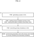
FIG. 2 is a flow diagram of a method for controlling backplane communication of an industrial system according to one embodiment. - The same reference number represents the same element or the same type of element on all drawings.
- It should be appreciated by those skilled in the art that any block diagrams herein represent conceptual views of illustrative systems embodying the principles of the present subject matter. Similarly, it will be appreciated that any flow charts, flow diagrams, state transition diagrams, pseudo code, and the like represent various processes which may be substantially represented in computer readable medium and so executed by a computer or processor, whether or not such computer or processor is explicitly shown.
- The figures and the following description illustrate specific exemplary embodiments of the invention. It will thus be appreciated that those skilled in the art will be able to devise various arrangements that, although not explicitly described or shown herein, embody the principles of the invention and are included within the scope of the invention. Furthermore, any examples described herein are intended to aid in understanding the principles of the invention, and are to be construed as being without limitation to such specifically recited examples and conditions. As a result, the invention is not limited to the specific embodiments or examples described below, but by the claims and their equivalents.
- In order to provide needed networking and communication support for Automated Control Systems, IEEE 802.1 time sensitive network (TSN) has emerged as a popular technology. TSN refers to the IEEE 802.1Q defined standard technology to provide deterministic messaging on standard Ethernet. TSN is a Layer 2 technology and is centrally managed and delivers guarantees of delivery and minimized jitter using time scheduling for those real-time applications that require determinism.
- The IEEE 802.1Q standards work at OSI Layer 2. TSN is an Ethernet standard, rather than an Internet Protocol (IP) standard. The forwarding decisions made by the TSN bridges use the Ethernet header contents, not the IP address. The payloads of the Ethernet frames can be anything and are not limited to IP. This means that TSN can be used in any environment and can carry the payload of any industrial application.
- Referring to
FIG. 1 , an industrial communication system comprises a cluster manager CM, a set of I/O modules IOM, base plates BP and a unidirectional communication line UCL. Furthermore, the industrial communication system comprises a multipoint communication line MCL linking the cluster manager CM and the set of I/O modules IOM. - The cluster manager CM is able to manage communication with a set of I/O modules IOM, up to 32, via the multipoint communication line like a multipoint low voltage differential signaling (MLVDS) bus, and optionally with another cluster manager via Ethernet and CAN (Controller Area Network) bus. The cluster manager CM is driven by a head that can drive other cluster managers. In one embodiment, the cluster manager is included in the head connected via a fieldbus to a control device like a PLC. In one embodiment, the head is also included in the PLC.
- An I/O module IOM can include Analog to Digital Converter (ADC) and Digital to Analog Converter (DAC) for connecting to sensors and the real world, communications modules, digital inputs and outputs, relays, and more. An I/O module communicates with the control manager CM through the communication bus with adapted packet formats.
- The base plates BP are respectively associated with the I/O modules that are plugged into them. The base plates BP may be designed to form a backplane for the set of I/O modules, each combination of base plate and associated I/O module forming a slice of the backplane.
- Each base plate is a passive base plate that offers no active bus driving circuitry, any desired arbitration logic being placed on the I/O module. A passive base plate is thus expected to not have a single point of failure (SPOF).
- The unidirectional communication line UCL is a physical medium configured to be coupled to multiple I/O modules and the cluster manager and provides a multi-drop capability from the cluster manager. More precisely, the cluster manager comprises a transmission port TPC and a reception port RPC on the unidirectional communication line and each Input/Output module comprises a reception port RPM on the unidirectional communication line. The unidirectional communication line is a signaling line allowing the cluster manager to send data that are received simultaneously by the cluster manager itself and the I/O modules, assuming the propagation time in the unidirectional communication line is negligible.
- The cluster manager CM comprises a primary switch PS and a primary control module PCM. The primary control module PCM controls the transmission port and the reception port on the unidirectional communication line, in order to transmit and receive data on this latter.
- An Input/Output module IOM comprises a secondary switch SS and a secondary control module SCM. The secondary control module SCM controls the reception port on the unidirectional communication line, in order to receive data on this latter.
- The primary switch PS and the secondary switch SS are defined as TSN switches which allow a communication between the cluster manager and an I/O module without any collision in the data traffic. As mentioned before, TSN is a technology that is focused on time, and was developed to provide a way to make sure information can travel from point A to point B in a fixed and predictable amount of time. The primary switch PS and the secondary switch SS implement respectively a primary clock and a secondary clock.
- The primary switch PS is a time-aware relay and implements for example the standard 802.1 AS-Rev, and can be synchronized in time in a gPTP domain which heads and other cluster managers belong to.
- The primary switch PS is able to run a gPTP stack in slave mode in the gPTP domain and is able to run a PTP stack, called sPTP, in master mode in a time domain, called sPTP domain, which the cluster manager and the I/O modules belong to. Thus a sPTP domain can be created for each cluster of I/O modules.
- The primary switch PS is configured to use the unidirectional communication line UCL to send a pulse that triggers a timestamp in any elements (I/O modules) of the backplane in order to synchronize the primary clock with the secondary clocks of the I/O modules. The unidirectional communication line is used to transport the time of the primary clock to all I/O modules.
- To that end, the secondary switch SS is able to run a sPTP stack in slave mode in order to be synchronized with the primary switch PS running a sPTP stack in master mode that can be updated in the gPTP domain.
- In this architecture, all the elements of a whole industrial system can be updated and synchronized in time: in the gPTP domain encompassing a northbound network and synchronizing all the cluster managers with heads, and in the sPTP domain encompassing a southbound network in each cluster of I/O modules and synchronizing all the I/O modules managers with their respective cluster manager.
- More specifically, the primary control module PCM is able to generate a periodic pulse via the transmission port on the unidirectional communication line. The pulse is then received on the reception port RPC of the cluster manager and the reception port RPM of each I/O module.
- Upon reception of the pulse, the primary control module PCM is able to create a primary timestamp from the primary clock of the primary switch and each secondary control module SCM is configured to create a secondary timestamp from the secondary clock of the corresponding secondary switch.
- The primary control module PCM transmits a message via the transmission port on the unidirectional communication line, the message being received by all I/O modules linked to the unidirectional communication line and comprising the primary timestamp. The message can further comprise an error-detecting code like a cyclic redundancy check (CRC) to determine if the message containing the primary timestamp contains errors or has been corrupted.
- Upon reception of the message, each I/O module is able to synchronize the secondary clock with the primary clock based on the received primary timestamp and the previously created secondary timestamp.
- As the primary timestamp was generated at the same time as the secondary timestamp, upon reception of the pulse, this mechanism allows the synchronization of the secondary clock with the primary clock and removes the delay from the line: delay measurement and compensation are not needed anymore in comparison with a classic PTP event message sequences that occur during synchronization.
- Once the all the clocks are synchronized, in the sPTP domain and thus in the gPTP domain, all switches have a common time reference for real-time communication with non-negotiable time boundaries for end-to-end transmission latencies. The cluster manager CM is thus synchronized in time with the set of I/O modules and is able to communicate with the set of I/O modules via the multipoint communication line MCL.
- The cluster manager CM further contains a packet processor that manages the data frames, like Ethernet frames, coming from the I/O modules through the primary switch PS via the multipoint communication line MCL. For example, the packet processor is able to extract the payload of each Ethernet frame, verify the signature of each payload, concatenate all payloads in one payload in only one concatenated Ethernet frame, calculate a new signature and send the concatenated Ethernet frame to a processing unit.
- The primary switch and the secondary switch define which ports are configured to send or received data. For example, a port of the switch may be configured to send a specific frame at a schedule time window. Especially, a switch manages different traffic queues according to the concept of Time-Aware Shaping (TAS) introduced by IEEE 802.1Qbv standard. Time-Aware Shaping enables determinism by dividing traffic in different preconfigured time-slots configured in a Gate-Control-Lists (GCL). The time aware shaper consists different traffic queues. Each queue is associated with a gate and has a transmission selection algorithm which selects the next packet transmitted from the queue. The queue can be organized in first in first out (FIFO). The state of a gate can either be open or close, and only open gates can transmit packets. A time aware gate opens and closes according to its configured time. The schedule of the gate states is specified in the GCL. Each entry of the list consists of a set of gate states and their duration.
- At each time cycle, the switch commands the opening of a gate for a scheduled time window for transmitting the data in the queue associated with said gate, the other gates remaining closed. At each time cycle, a switch may send data in a static time window, control data in another static time window, and potentially service data in a dynamic time window that is scheduled by the cluster manager.
- Thanks to the synchronized clocks of the switches of the I/O modules, all the I/O modules can share the multipoint communication line MCL to transmit I/O data at respective scheduled static time windows with deterministic latency at each time cycle. Thanks to the IEEE 802.1Qbv time-aware scheduler, at least one I/O module can transmit service data on the communication bus at a scheduled dynamic time windows in a best effort way.
- With reference to
FIG. 2 , a method for controlling backplane communication according to one embodiment of the invention comprises steps S1 to S4. - In step S1, the primary control module PCM generates a pulse via the transmission port TPC on the unidirectional communication line UCL. The pulse is received by each I/O module on its reception port RPM and by the cluster manager itself on the reception port RPC.
- In step S2, upon reception of the pulse, the primary control module PCM creates a primary timestamp from the primary clock of the primary switch PS. To that end, the primary control module PCM interrogates and captures the master PTP time base corresponding to the primary clock of the primary switch PS. The value of the master PTP time base captured by the primary control module PCM is sampled to create the primary timestamp.
- At the same time upon reception of the pulse at each I/O module, because the path delay is considered null or negligible, the secondary control module SCM creates a secondary timestamp from the secondary clock of the corresponding secondary switch SS. Similarly, the secondary control module SCM interrogates and captures the master PTP time base corresponding to the secondary clock of the secondary switch SS.
- In step S3, the primary control module PCM transmits a message via the transmission port on the unidirectional communication line, the message comprising the primary timestamp and an error-detecting code. The message is received by each I/O module on its reception port RPM and by the cluster manager itself on the reception port RPC.
- In step S4, after reception of the message, the secondary control module SCM of each I/O module is able to synchronize the secondary clock with the primary clock based on the received primary timestamp and the previously created secondary timestamp.
- In one embodiment, the cluster manager implements two components operating the primary switch PS. A first component operates as described before, with the gPTP stack in slave mode and the sPTP stack in master mode. A second component runs only a sPTP stack in slave mode in a similar way as a secondary switch of a I/O module.
- Besides the I/O modules, after reception of the message, the cluster manager is able to synchronize an auxiliary clock with the primary clock based on the received primary timestamp and a previously created secondary timestamp by the auxiliary clock in step S2 upon reception of the pulse.
- Although the present invention has been described above with reference to specific embodiments, it is not intended to be limited to the specific form set forth herein. Rather, the invention is limited only by the accompanying claims and, other embodiments than the specific above are equally possible within the scope of these appended claims.
- Furthermore, although exemplary embodiments have been described above in some exemplary combination of components and/or functions, it should be appreciated that, alternative embodiments may be provided by different combinations of members and/or functions without departing from the scope of the present disclosure. In addition, it is specifically contemplated that a particular feature described, either individually or as part of an embodiment, can be combined with other individually described features, or parts of other embodiments
Claims (10)
- An industrial system for controlling backplane communication, comprising:a cluster manager (CM) comprising a primary switch (PS) linked to a primary control module (PCM),at least one Input/Output, I/O, module (IOM) comprising a secondary switch (SS) linked to a secondary control module (SCM),a unidirectional communication line (UCL) linking the cluster manager (CM) to the at least one I/O module (IOM) through passive base plates (BP),wherein the cluster manager (CM) comprises a transmission port (TPC) and a reception port (RPC) on the unidirectional communication line and the at least one Input/Output module (IOM) comprises a reception port (RPM) on the unidirectional communication line,wherein the primary control module is configured to generate a pulse via the transmission port (TPC) on the unidirectional communication line,wherein, upon reception of the pulse, the primary control module (PCM) is configured to create a primary timestamp from a primary clock of the primary switch and the secondary control module (SCM) is configured to create a secondary timestamp from a secondary clock of the secondary switch,wherein the primary control module (PCM) is configured to send a message via the transmission port (TPC) on the unidirectional communication line to the secondary control module, the message comprising the primary timestamp,wherein, upon reception of the message, the secondary control module (SCM) is configured to synchronize the secondary clock with the primary clock based on the received primary timestamp and secondary timestamp.
- An industrial system according to claim 1, wherein the primary timestamp and the secondary timestamp are created simultaneously, the path delay between the reception port (RPC) of the cluster manager (CM) and the reception port (RPM) of the at least one Input/Output module (IOM) being considered null or negligible.
- An industrial system according to any of previous claims, wherein the cluster manager (CM) is further linked to the at least one IO module (IOM) via a multipoint communication line (MCL) allowing the cluster manager to transmit data in frames on the multipoint communication line (MCL) at scheduled time windows to the at least one IO module (IOM) when the primary clock and the secondary clock are synchronized.
- An industrial system according to any of previous claims, wherein the primary switch and the secondary switch are Time Sensitive Networking switches.
- An industrial system according to any of previous claims, wherein the primary switch and the secondary switch are implemented with the IEEE 802.1 Qbv time-aware scheduler to schedule static time windows and dynamic time windows.
- An industrial system according to any of previous claims, wherein the primary clock and the secondary clock are synchronized based on Precision Time Protocol.
- An industrial system according to any of previous claims, wherein the primary clock is able to be synchronized in time based on a Generalized Precision Time Protocol in a time domain which other cluster managers belong to.
- An industrial system according to any of previous claims, wherein the message further comprises an error-detecting code to determine if the message contains errors.
- A method for controlling backplane communication of an industrial system that comprises:a cluster manager (CM) comprising a primary switch (PS) linked to a primary control module (PCM),at least one Input/Output, I/O, module (IOM) comprising a secondary switch (SS) linked to a secondary control module (SCM),a unidirectional communication line (UCL) linking the cluster manager (CM) to the at least one IO module (IOM) through passive base plates (BP),wherein the cluster manager (CM) comprises a transmission port (TPC) and a reception port (RPC) on the unidirectional communication line and the at least one Input/Output module (IOM) comprises a reception port (RPM) on the unidirectional communication line,the method comprising:generating, by the primary control module (PCM), a pulse via the transmission port (TPC) on the unidirectional communication line,creating, by the primary control module (PCM), upon reception of the pulse, a primary timestamp from a primary clock of the primary switch and the secondary control module (SCM) is configured to create a secondary timestamp from a secondary clock of the secondary switch,sending, by the primary control module (PCM), a message via the transmission port on the unidirectional communication line to the secondary control module, the message comprising the primary timestamp,synchronizing, by the secondary control module (SCM), upon reception of the message, the secondary clock with the primary clock based on the received primary timestamp and secondary timestamp.
- A computer-readable medium having embodied thereon a computer program for executing a method for controlling backplane communication of an industrial system according to any of claims 1 to 8.
Priority Applications (5)
| Application Number | Priority Date | Filing Date | Title |
|---|---|---|---|
| ES21306240T ES3033772T3 (en) | 2021-09-10 | 2021-09-10 | Synchronization for backplane communication |
| EP21306240.9A EP4149028B1 (en) | 2021-09-10 | 2021-09-10 | Synchronization for backplane communication |
| BR102022011489-7A BR102022011489A2 (en) | 2021-09-10 | 2022-06-10 | COMMUNICATION SYNCHRONIZATION VIA DATA BUS |
| CN202210856012.9A CN115801162A (en) | 2021-09-10 | 2022-07-11 | Synchronization for backplane communications |
| US17/900,903 US20230078505A1 (en) | 2021-09-10 | 2022-09-01 | Synchronization for backplane communication |
Applications Claiming Priority (1)
| Application Number | Priority Date | Filing Date | Title |
|---|---|---|---|
| EP21306240.9A EP4149028B1 (en) | 2021-09-10 | 2021-09-10 | Synchronization for backplane communication |
Publications (2)
| Publication Number | Publication Date |
|---|---|
| EP4149028A1 true EP4149028A1 (en) | 2023-03-15 |
| EP4149028B1 EP4149028B1 (en) | 2025-05-28 |
Family
ID=78000648
Family Applications (1)
| Application Number | Title | Priority Date | Filing Date |
|---|---|---|---|
| EP21306240.9A Active EP4149028B1 (en) | 2021-09-10 | 2021-09-10 | Synchronization for backplane communication |
Country Status (5)
| Country | Link |
|---|---|
| US (1) | US20230078505A1 (en) |
| EP (1) | EP4149028B1 (en) |
| CN (1) | CN115801162A (en) |
| BR (1) | BR102022011489A2 (en) |
| ES (1) | ES3033772T3 (en) |
Citations (1)
| Publication number | Priority date | Publication date | Assignee | Title |
|---|---|---|---|---|
| EP1717978A1 (en) * | 2005-04-27 | 2006-11-02 | Rockwell Automation Technologies, Inc. | Time synchronization, deterministic data delivery and redundancy for cascaded nodes on full duplex ethernet networks |
Family Cites Families (5)
| Publication number | Priority date | Publication date | Assignee | Title |
|---|---|---|---|---|
| US12464041B2 (en) * | 2019-02-13 | 2025-11-04 | Telefonaktiebolaget Lm Ericsson (Publ) | Industrial automation with 5G and beyond |
| US11503557B2 (en) * | 2020-06-18 | 2022-11-15 | Kabushiki Kaisha Toshiba | Time synchronization in integrated 5G wireless and time-sensitive networking systems |
| US11575599B2 (en) * | 2021-02-24 | 2023-02-07 | Nokia Solutions And Networks Oy | Multi-tier deterministic networking |
| EP4349085B1 (en) * | 2021-06-04 | 2026-05-06 | Telefonaktiebolaget LM Ericsson (publ) | Improving time synchronization accuracy in a wireless network |
| CN117917065A (en) * | 2021-07-15 | 2024-04-19 | 通用电气公司 | Systems and methods for configuring network slices for time-sensitive networks |
-
2021
- 2021-09-10 EP EP21306240.9A patent/EP4149028B1/en active Active
- 2021-09-10 ES ES21306240T patent/ES3033772T3/en active Active
-
2022
- 2022-06-10 BR BR102022011489-7A patent/BR102022011489A2/en unknown
- 2022-07-11 CN CN202210856012.9A patent/CN115801162A/en active Pending
- 2022-09-01 US US17/900,903 patent/US20230078505A1/en active Pending
Patent Citations (1)
| Publication number | Priority date | Publication date | Assignee | Title |
|---|---|---|---|---|
| EP1717978A1 (en) * | 2005-04-27 | 2006-11-02 | Rockwell Automation Technologies, Inc. | Time synchronization, deterministic data delivery and redundancy for cascaded nodes on full duplex ethernet networks |
Non-Patent Citations (1)
| Title |
|---|
| LEYRER THOMAS ET AL: "Analysis and implementation of multi-protocol gigabit Ethernet switch for real-time control systems", 2021 IEEE INTERNATIONAL CONFERENCE ON COMMUNICATIONS WORKSHOPS (ICC WORKSHOPS), IEEE, 14 June 2021 (2021-06-14), pages 1 - 6, XP033939040, DOI: 10.1109/ICCWORKSHOPS50388.2021.9473718 * |
Also Published As
| Publication number | Publication date |
|---|---|
| BR102022011489A2 (en) | 2023-03-14 |
| ES3033772T3 (en) | 2025-08-07 |
| US20230078505A1 (en) | 2023-03-16 |
| CN115801162A (en) | 2023-03-14 |
| EP4149028B1 (en) | 2025-05-28 |
Similar Documents
| Publication | Publication Date | Title |
|---|---|---|
| US12362899B2 (en) | Time synchronization in industrial system | |
| CN102237718B (en) | Method and device of operating wind power electric field power network with improved data transmission protocol | |
| US7411966B2 (en) | Method and system for coupling data networks | |
| US12068970B2 (en) | Multipoint ethernet bus | |
| EP3903454B1 (en) | A tsn enabled controller | |
| EP1717978B1 (en) | Time synchronization, deterministic data delivery and redundancy for cascaded nodes on full duplex ethernet networks | |
| EP3883214B1 (en) | A method for implementing an industrial communication gateway | |
| WO2021079599A1 (en) | Control device and distributed control system | |
| US20070058682A1 (en) | Method for optimizing bandwidth utilization in bus systems | |
| US8792518B2 (en) | Automation system | |
| CN102918820B (en) | At the method and apparatus of two exchanged between equipment data of automated network | |
| US7770085B2 (en) | Replacement messages for identifying and preventing errors during the transmission of real time-critical data | |
| EP4149028B1 (en) | Synchronization for backplane communication | |
| Sandic et al. | Impact of anomalies within TTEthernet network on synchronization protocol: Analysis using OMNeT++ simulations | |
| CN119363844A (en) | A deterministic protocol conversion method for multi-protocol industrial equipment | |
| US20240356666A1 (en) | Absolute time in industrial system | |
| US20040105398A1 (en) | Method and electronic switching circuit for a scalable communication interface in automation components | |
| US20240356646A1 (en) | Optical ethernet bus | |
| Hantel et al. | The integration of time-sensitive networking into EtherNet/IP technologies | |
| Li et al. | TSN-Based Scheduling of Task-Network Co-Scheduling on In-Vehicle Multi-Core System | |
| Gou et al. | An Efficient UDP Enhancement Method for Modbus in Generic Networks | |
| Mateu | ENHANCING TSN ADOPTION BY INDUSTRY | |
| Ethernet | IEEE TSN (Time-Sensitive Networking): A Deterministic Ethernet Standard | |
| Fu et al. | Delay characteristics and synchronization architecture of networked control system | |
| Suethanuwong | Performance evaluation and optimization of standard-ethernet traffic in TTEthernet systems |
Legal Events
| Date | Code | Title | Description |
|---|---|---|---|
| PUAI | Public reference made under article 153(3) epc to a published international application that has entered the european phase |
Free format text: ORIGINAL CODE: 0009012 |
|
| STAA | Information on the status of an ep patent application or granted ep patent |
Free format text: STATUS: THE APPLICATION HAS BEEN PUBLISHED |
|
| AK | Designated contracting states |
Kind code of ref document: A1 Designated state(s): AL AT BE BG CH CY CZ DE DK EE ES FI FR GB GR HR HU IE IS IT LI LT LU LV MC MK MT NL NO PL PT RO RS SE SI SK SM TR |
|
| STAA | Information on the status of an ep patent application or granted ep patent |
Free format text: STATUS: REQUEST FOR EXAMINATION WAS MADE |
|
| 17P | Request for examination filed |
Effective date: 20230913 |
|
| RBV | Designated contracting states (corrected) |
Designated state(s): AL AT BE BG CH CY CZ DE DK EE ES FI FR GB GR HR HU IE IS IT LI LT LU LV MC MK MT NL NO PL PT RO RS SE SI SK SM TR |
|
| GRAP | Despatch of communication of intention to grant a patent |
Free format text: ORIGINAL CODE: EPIDOSNIGR1 |
|
| STAA | Information on the status of an ep patent application or granted ep patent |
Free format text: STATUS: GRANT OF PATENT IS INTENDED |
|
| GRAS | Grant fee paid |
Free format text: ORIGINAL CODE: EPIDOSNIGR3 |
|
| GRAA | (expected) grant |
Free format text: ORIGINAL CODE: 0009210 |
|
| STAA | Information on the status of an ep patent application or granted ep patent |
Free format text: STATUS: THE PATENT HAS BEEN GRANTED |
|
| INTG | Intention to grant announced |
Effective date: 20250327 |
|
| AK | Designated contracting states |
Kind code of ref document: B1 Designated state(s): AL AT BE BG CH CY CZ DE DK EE ES FI FR GB GR HR HU IE IS IT LI LT LU LV MC MK MT NL NO PL PT RO RS SE SI SK SM TR |
|
| REG | Reference to a national code |
Ref country code: GB Ref legal event code: FG4D |
|
| REG | Reference to a national code |
Ref country code: CH Ref legal event code: EP |
|
| REG | Reference to a national code |
Ref country code: IE Ref legal event code: FG4D Ref country code: DE Ref legal event code: R096 Ref document number: 602021031399 Country of ref document: DE |
|
| REG | Reference to a national code |
Ref country code: ES Ref legal event code: FG2A Ref document number: 3033772 Country of ref document: ES Kind code of ref document: T3 Effective date: 20250807 |
|
| REG | Reference to a national code |
Ref country code: NL Ref legal event code: MP Effective date: 20250528 |
|
| PG25 | Lapsed in a contracting state [announced via postgrant information from national office to epo] |
Ref country code: FI Free format text: LAPSE BECAUSE OF FAILURE TO SUBMIT A TRANSLATION OF THE DESCRIPTION OR TO PAY THE FEE WITHIN THE PRESCRIBED TIME-LIMIT Effective date: 20250528 |
|
| PGFP | Annual fee paid to national office [announced via postgrant information from national office to epo] |
Ref country code: DE Payment date: 20250926 Year of fee payment: 5 |
|
| REG | Reference to a national code |
Ref country code: LT Ref legal event code: MG9D |
|
| PG25 | Lapsed in a contracting state [announced via postgrant information from national office to epo] |
Ref country code: NO Free format text: LAPSE BECAUSE OF FAILURE TO SUBMIT A TRANSLATION OF THE DESCRIPTION OR TO PAY THE FEE WITHIN THE PRESCRIBED TIME-LIMIT Effective date: 20250828 Ref country code: GR Free format text: LAPSE BECAUSE OF FAILURE TO SUBMIT A TRANSLATION OF THE DESCRIPTION OR TO PAY THE FEE WITHIN THE PRESCRIBED TIME-LIMIT Effective date: 20250829 |
|
| PG25 | Lapsed in a contracting state [announced via postgrant information from national office to epo] |
Ref country code: NL Free format text: LAPSE BECAUSE OF FAILURE TO SUBMIT A TRANSLATION OF THE DESCRIPTION OR TO PAY THE FEE WITHIN THE PRESCRIBED TIME-LIMIT Effective date: 20250528 Ref country code: PL Free format text: LAPSE BECAUSE OF FAILURE TO SUBMIT A TRANSLATION OF THE DESCRIPTION OR TO PAY THE FEE WITHIN THE PRESCRIBED TIME-LIMIT Effective date: 20250528 |
|
| PGFP | Annual fee paid to national office [announced via postgrant information from national office to epo] |
Ref country code: IT Payment date: 20250922 Year of fee payment: 5 |
|
| PG25 | Lapsed in a contracting state [announced via postgrant information from national office to epo] |
Ref country code: BG Free format text: LAPSE BECAUSE OF FAILURE TO SUBMIT A TRANSLATION OF THE DESCRIPTION OR TO PAY THE FEE WITHIN THE PRESCRIBED TIME-LIMIT Effective date: 20250528 |
|
| PGFP | Annual fee paid to national office [announced via postgrant information from national office to epo] |
Ref country code: GB Payment date: 20250923 Year of fee payment: 5 |
|
| PG25 | Lapsed in a contracting state [announced via postgrant information from national office to epo] |
Ref country code: HR Free format text: LAPSE BECAUSE OF FAILURE TO SUBMIT A TRANSLATION OF THE DESCRIPTION OR TO PAY THE FEE WITHIN THE PRESCRIBED TIME-LIMIT Effective date: 20250528 |
|
| PGFP | Annual fee paid to national office [announced via postgrant information from national office to epo] |
Ref country code: FR Payment date: 20250925 Year of fee payment: 5 Ref country code: AT Payment date: 20251020 Year of fee payment: 5 |
|
| PG25 | Lapsed in a contracting state [announced via postgrant information from national office to epo] |
Ref country code: RS Free format text: LAPSE BECAUSE OF FAILURE TO SUBMIT A TRANSLATION OF THE DESCRIPTION OR TO PAY THE FEE WITHIN THE PRESCRIBED TIME-LIMIT Effective date: 20250828 |
|
| PG25 | Lapsed in a contracting state [announced via postgrant information from national office to epo] |
Ref country code: IS Free format text: LAPSE BECAUSE OF FAILURE TO SUBMIT A TRANSLATION OF THE DESCRIPTION OR TO PAY THE FEE WITHIN THE PRESCRIBED TIME-LIMIT Effective date: 20250928 |
|
| PG25 | Lapsed in a contracting state [announced via postgrant information from national office to epo] |
Ref country code: LV Free format text: LAPSE BECAUSE OF FAILURE TO SUBMIT A TRANSLATION OF THE DESCRIPTION OR TO PAY THE FEE WITHIN THE PRESCRIBED TIME-LIMIT Effective date: 20250528 |
|
| REG | Reference to a national code |
Ref country code: AT Ref legal event code: MK05 Ref document number: 1799263 Country of ref document: AT Kind code of ref document: T Effective date: 20250528 |
|
| PG25 | Lapsed in a contracting state [announced via postgrant information from national office to epo] |
Ref country code: DK Free format text: LAPSE BECAUSE OF FAILURE TO SUBMIT A TRANSLATION OF THE DESCRIPTION OR TO PAY THE FEE WITHIN THE PRESCRIBED TIME-LIMIT Effective date: 20250528 Ref country code: AT Free format text: LAPSE BECAUSE OF FAILURE TO SUBMIT A TRANSLATION OF THE DESCRIPTION OR TO PAY THE FEE WITHIN THE PRESCRIBED TIME-LIMIT Effective date: 20250528 Ref country code: SM Free format text: LAPSE BECAUSE OF FAILURE TO SUBMIT A TRANSLATION OF THE DESCRIPTION OR TO PAY THE FEE WITHIN THE PRESCRIBED TIME-LIMIT Effective date: 20250528 |
|
| PG25 | Lapsed in a contracting state [announced via postgrant information from national office to epo] |
Ref country code: CZ Free format text: LAPSE BECAUSE OF FAILURE TO SUBMIT A TRANSLATION OF THE DESCRIPTION OR TO PAY THE FEE WITHIN THE PRESCRIBED TIME-LIMIT Effective date: 20250528 |
|
| PG25 | Lapsed in a contracting state [announced via postgrant information from national office to epo] |
Ref country code: EE Free format text: LAPSE BECAUSE OF FAILURE TO SUBMIT A TRANSLATION OF THE DESCRIPTION OR TO PAY THE FEE WITHIN THE PRESCRIBED TIME-LIMIT Effective date: 20250528 |
|
| PG25 | Lapsed in a contracting state [announced via postgrant information from national office to epo] |
Ref country code: SK Free format text: LAPSE BECAUSE OF FAILURE TO SUBMIT A TRANSLATION OF THE DESCRIPTION OR TO PAY THE FEE WITHIN THE PRESCRIBED TIME-LIMIT Effective date: 20250528 |
|
| PGFP | Annual fee paid to national office [announced via postgrant information from national office to epo] |
Ref country code: ES Payment date: 20251015 Year of fee payment: 5 |
|
| REG | Reference to a national code |
Ref country code: DE Ref legal event code: R097 Ref document number: 602021031399 Country of ref document: DE |
|
| PG25 | Lapsed in a contracting state [announced via postgrant information from national office to epo] |
Ref country code: RO Free format text: LAPSE BECAUSE OF FAILURE TO SUBMIT A TRANSLATION OF THE DESCRIPTION OR TO PAY THE FEE WITHIN THE PRESCRIBED TIME-LIMIT Effective date: 20250528 |
|
| PLBE | No opposition filed within time limit |
Free format text: ORIGINAL CODE: 0009261 |
|
| STAA | Information on the status of an ep patent application or granted ep patent |
Free format text: STATUS: NO OPPOSITION FILED WITHIN TIME LIMIT |
|
| REG | Reference to a national code |
Ref country code: CH Ref legal event code: L10 Free format text: ST27 STATUS EVENT CODE: U-0-0-L10-L00 (AS PROVIDED BY THE NATIONAL OFFICE) Effective date: 20260409 |
|
| REG | Reference to a national code |
Ref country code: CH Ref legal event code: H13 Free format text: ST27 STATUS EVENT CODE: U-0-0-H10-H13 (AS PROVIDED BY THE NATIONAL OFFICE) Effective date: 20260504 |
|
| 26N | No opposition filed |
Effective date: 20260303 |