EP4148948A1 - Battery protection circuit and protection method thereof - Google Patents
Battery protection circuit and protection method thereof Download PDFInfo
- Publication number
- EP4148948A1 EP4148948A1 EP21861984.9A EP21861984A EP4148948A1 EP 4148948 A1 EP4148948 A1 EP 4148948A1 EP 21861984 A EP21861984 A EP 21861984A EP 4148948 A1 EP4148948 A1 EP 4148948A1
- Authority
- EP
- European Patent Office
- Prior art keywords
- battery cell
- voltage
- battery
- sensing line
- current
- Prior art date
- Legal status (The legal status is an assumption and is not a legal conclusion. Google has not performed a legal analysis and makes no representation as to the accuracy of the status listed.)
- Pending
Links
Images
Classifications
-
- H—ELECTRICITY
- H02—GENERATION; CONVERSION OR DISTRIBUTION OF ELECTRIC POWER
- H02J—ELECTRIC POWER NETWORKS; CIRCUIT ARRANGEMENTS OR SYSTEMS FOR SUPPLYING OR DISTRIBUTING ELECTRIC POWER; SYSTEMS FOR STORING ELECTRIC ENERGY
- H02J7/00—Circuit arrangements for charging or discharging batteries or for supplying loads from batteries
- H02J7/60—Circuit arrangements for charging or discharging batteries or for supplying loads from batteries including safety or protection arrangements
- H02J7/663—Circuit arrangements for charging or discharging batteries or for supplying loads from batteries including safety or protection arrangements using battery or load disconnect circuits
-
- G—PHYSICS
- G01—MEASURING; TESTING
- G01R—MEASURING ELECTRIC VARIABLES; MEASURING MAGNETIC VARIABLES
- G01R19/00—Arrangements for measuring currents or voltages or for indicating presence or sign thereof
- G01R19/165—Indicating that current or voltage is either above or below a predetermined value or within or outside a predetermined range of values
- G01R19/16533—Indicating that current or voltage is either above or below a predetermined value or within or outside a predetermined range of values characterised by the application
- G01R19/16538—Indicating that current or voltage is either above or below a predetermined value or within or outside a predetermined range of values characterised by the application in AC or DC supplies
- G01R19/16542—Indicating that current or voltage is either above or below a predetermined value or within or outside a predetermined range of values characterised by the application in AC or DC supplies for batteries
-
- G—PHYSICS
- G01—MEASURING; TESTING
- G01R—MEASURING ELECTRIC VARIABLES; MEASURING MAGNETIC VARIABLES
- G01R31/00—Arrangements for testing electric properties; Arrangements for locating electric faults; Arrangements for electrical testing characterised by what is being tested not provided for elsewhere
- G01R31/36—Arrangements for testing, measuring or monitoring the electrical condition of accumulators or electric batteries, e.g. capacity or state of charge [SoC]
- G01R31/382—Arrangements for monitoring battery or accumulator variables, e.g. SoC
- G01R31/3842—Arrangements for monitoring battery or accumulator variables, e.g. SoC combining voltage and current measurements
-
- H—ELECTRICITY
- H02—GENERATION; CONVERSION OR DISTRIBUTION OF ELECTRIC POWER
- H02J—ELECTRIC POWER NETWORKS; CIRCUIT ARRANGEMENTS OR SYSTEMS FOR SUPPLYING OR DISTRIBUTING ELECTRIC POWER; SYSTEMS FOR STORING ELECTRIC ENERGY
- H02J7/00—Circuit arrangements for charging or discharging batteries or for supplying loads from batteries
- H02J7/60—Circuit arrangements for charging or discharging batteries or for supplying loads from batteries including safety or protection arrangements
- H02J7/61—Circuit arrangements for charging or discharging batteries or for supplying loads from batteries including safety or protection arrangements against overcharge
-
- H—ELECTRICITY
- H02—GENERATION; CONVERSION OR DISTRIBUTION OF ELECTRIC POWER
- H02J—ELECTRIC POWER NETWORKS; CIRCUIT ARRANGEMENTS OR SYSTEMS FOR SUPPLYING OR DISTRIBUTING ELECTRIC POWER; SYSTEMS FOR STORING ELECTRIC ENERGY
- H02J7/00—Circuit arrangements for charging or discharging batteries or for supplying loads from batteries
- H02J7/60—Circuit arrangements for charging or discharging batteries or for supplying loads from batteries including safety or protection arrangements
- H02J7/62—Circuit arrangements for charging or discharging batteries or for supplying loads from batteries including safety or protection arrangements against overcurrent
-
- H—ELECTRICITY
- H02—GENERATION; CONVERSION OR DISTRIBUTION OF ELECTRIC POWER
- H02J—ELECTRIC POWER NETWORKS; CIRCUIT ARRANGEMENTS OR SYSTEMS FOR SUPPLYING OR DISTRIBUTING ELECTRIC POWER; SYSTEMS FOR STORING ELECTRIC ENERGY
- H02J7/00—Circuit arrangements for charging or discharging batteries or for supplying loads from batteries
- H02J7/60—Circuit arrangements for charging or discharging batteries or for supplying loads from batteries including safety or protection arrangements
- H02J7/63—Circuit arrangements for charging or discharging batteries or for supplying loads from batteries including safety or protection arrangements against overdischarge
-
- H—ELECTRICITY
- H02—GENERATION; CONVERSION OR DISTRIBUTION OF ELECTRIC POWER
- H02J—ELECTRIC POWER NETWORKS; CIRCUIT ARRANGEMENTS OR SYSTEMS FOR SUPPLYING OR DISTRIBUTING ELECTRIC POWER; SYSTEMS FOR STORING ELECTRIC ENERGY
- H02J7/00—Circuit arrangements for charging or discharging batteries or for supplying loads from batteries
- H02J7/80—Circuit arrangements for charging or discharging batteries or for supplying loads from batteries including monitoring or indicating arrangements
-
- Y—GENERAL TAGGING OF NEW TECHNOLOGICAL DEVELOPMENTS; GENERAL TAGGING OF CROSS-SECTIONAL TECHNOLOGIES SPANNING OVER SEVERAL SECTIONS OF THE IPC; TECHNICAL SUBJECTS COVERED BY FORMER USPC CROSS-REFERENCE ART COLLECTIONS [XRACs] AND DIGESTS
- Y02—TECHNOLOGIES OR APPLICATIONS FOR MITIGATION OR ADAPTATION AGAINST CLIMATE CHANGE
- Y02E—REDUCTION OF GREENHOUSE GAS [GHG] EMISSIONS, RELATED TO ENERGY GENERATION, TRANSMISSION OR DISTRIBUTION
- Y02E60/00—Enabling technologies; Technologies with a potential or indirect contribution to GHG emissions mitigation
- Y02E60/10—Energy storage using batteries
Definitions
- the present invention relates to a battery protection circuit and a method for protecting the same, and more particularly, to a battery protection circuit for protecting a battery from overcharge, overdischarge and overcurrent, and a method for protecting the same.
- Batteries are widely used in various fields ranging from small electronic devices such as smart phones, laptops, and tablet PCs to electric vehicles and energy storage systems (ESS).
- ESS energy storage systems
- a battery protection circuit that protects the battery from overcharge, overdischarge, overcurrent, and short circuit is used.
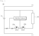
- the battery protection circuit 20 configures the charge/discharge FETs 22a and 22b on the current path between the battery cell 10 and the output unit 30 to the external system, and uses a method of protecting the battery by blocking the abnormal current by turning off the charge/discharge FETs 22a and 22b when an abnormality such as overcharge, overdischarge, or overcurrent occurs.
- the charge/discharge FETs 22a and 22b configured on the current path must use low-resistance FETs having a small resistance value in order to prevent current loss and heat generated by the current flowing through the current path.
- low-resistance FETs have the disadvantage of being larger and more expensive than general FETs, so that this causes problems such as an increase in price and size of the battery protection circuit, and an increase in internal resistance of the battery.
- Patent Document 1 KR2045999 B1
- An object of the present invention is to provide a battery protection circuit and method for protecting a battery from abnormal situations such as overcharge, overdischarge, and overcurrent by using a general FET.
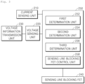
- a battery protection circuit for protecting one or more battery cells from abnormal situations including overcharge, overdischarge and overcurrent includes: a current sensing unit connected in series on a current output path formed between one terminal of the battery cell and an output unit to an external system and configured to sense a current of the battery cell flowing in the path; a voltage sensing unit connected to a voltage sensing line connected to both ends of the battery cell to sense a voltage of the battery cell; a voltage information transmission unit configured to transmit a voltage value of a battery cell sensed by the voltage sensing unit to the external system; a control unit configured to determine whether an abnormal situation occurs in a battery cell using a sensing values of the current sensing unit and the voltage sensing unit, and disconnect the voltage sensing line according to the determination result; and a sensing line blocking FET provided on the voltage sensing line to be turned off under the control of the control unit to disconnect the voltage sensing line.
- control unit includes: a first determination unit configured to compare whether the voltage value of the battery cell sensed by the voltage sensing unit is equal to or greater than a predetermined first reference value, and determine that the battery cell is in an overcharge state and output an overcharge signal when the voltage value of the battery cell is greater than or equal to a predetermined first reference value; a second determination unit configured to compare whether the voltage value of the battery cell sensed by the voltage sensing unit is less than or equal to a predetermined second reference value, determine that the battery cell is in an over-discharge state and output an overdischarge signal when the voltage value of the battery cell is less than or equal to a predetermined second reference value; a third determination unit configured to compare whether the current value of the battery cell sensed by the current sensing unit is equal to or greater than a predetermined third reference value, and determine that the battery cell is in an overcurrent state and output an overcurrent signal when the current value of the battery cell is equal to or greater than a predetermined third reference value; and a blocking FET control unit configured
- the voltage of the battery cell sensed by the voltage sensing unit is 0 V.
- the external system senses that the current battery cell is in a low voltage state and turns off the system power by itself.
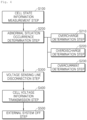
- a method of protecting one or more battery cells from abnormal situations including overcharge, overdischarge and overcurrent includes: a cell state information measurement step of measuring current and voltage values of a battery cell at predetermined periodic intervals through a sensing resistor provided on a current output path between the battery cell and an output unit to an external system and a voltage sensing line connected to both ends of the battery cell; an abnormal situation occurrence determination step of determining whether an abnormal situation occurs in a battery cell using the current and voltage values of the battery cell measured in the cell state information measurement step; a voltage sensing line disconnection step of disconnecting the voltage sensing line when it is determined that an abnormal situation occurs in the battery cell by the abnormal situation occurrence determination step; a cell voltage information transmission step of transmitting a voltage value of a battery cell measured through a voltage sensing line disconnected by the voltage sensing line disconnection step to an external system; and an external system power off step of automatically turning off the system power in the external system receiving the voltage value of the battery cell measured through the disconnected voltage sensing line through the cell voltage information transmission step.
- the abnormal situation occurrence determination step includes: an overcharge determination step of comparing whether the voltage value of the battery cell measured in the cell state information measurement step is equal to or greater than a predetermined first reference value, and determining that the battery cell is in an overcharge state when the voltage value of the battery cell is equal to or greater than a predetermined first reference value; an overdischarge determination step of comparing whether the voltage value of the battery cell measured in the cell state information measurement step is less than or equal to a predetermined second reference value, and determining that the battery cell is in an overdischarge state when the voltage value of the battery cell is less than or equal to a predetermined second reference value; and an overcurrent determination step of comparing whether the current value of the battery cell measured in the cell state information measurement step is equal to or greater than a predetermined third reference value, and determining that the battery cell is in an overcurrent state when the current value of the battery cell is equal to or greater than a predetermined third reference value, wherein when any one of the overcharge, the overdischarge and the overcurrent
- the voltage sensing line disconnection step includes turning off a sensing line blocking FET configured on the voltage sensing line.
- the voltage value of the battery cell transmitted to the external system is 0 V.
- the external system off step senses that the current battery cell is in a low voltage state and turns off the system power when the 0 V voltage value of the battery cell is transmitted by the cell voltage information transmission step in the external system.
- a battery pack includes such a battery protection circuit.
- the battery protection circuit of the present invention uses a general FET instead of a low resistance FET to protect the battery from abnormal situations such as overcharge, overdischarge, and overcurrent, thereby reducing the price and size of the battery protection circuit. In addition, there is an effect that the internal resistance of the battery is reduced.
- the battery protection circuit 200 of the present invention is a configuration that protects a battery cell from abnormal situations including overcharge, overdischarge, and overcurrent, and may include the following configuration.
- the current output path is formed between one terminal of the battery cell 100 and the output unit 300 to an external system (not shown), and is a path through which current flows from the battery cell 100 to the output unit 300, and may supply power to an external system (not shown) through this path.
- the external system refers to an electronic device including, for example, a mobile phone, a laptop computer, a tablet PC, etc., which is a connected to a connector (not shown) of the battery pack and uses the current from the battery cell 100 as driving power.
- the present invention is not limited thereto, and there may be more than one battery cell.
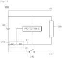
- the voltage sensing line is a configuration for sensing the voltage of the battery cell 100, and is connected to both ends of the battery cell 100 as shown in FIG. 2 , and the voltage sensing line L2 connected to the negative portion of the battery cell 100 may be connected in parallel to the current output path L1.
- This voltage sensing line is a general configuration configured in the battery protection circuit to sense the voltage of the battery cell 100, and unlike conventional voltage sensing lines, the voltage sensing line of the present invention is different in that the FET 240 that disconnects the voltage sensing line is placed in the middle.
- the present invention is to solve the above-mentioned problems by connecting the FET 240 to the voltage sensing line L2 instead of connecting the charge/discharge FET to the current output path L1. The principle will be described in detail when the control unit 250 is described below.
- the current sensing unit is a configuration that is connected in series on the current output path L1 to sense the current of the battery cell 100 flowing in the path, and may include, for example, a shunt resistor.
- the shunt resistor is a resistor for measuring current having a very low resistance value and high precision, and measures the current by using a voltage applied to the resistor generated according to the magnitude of the current.
- the voltage sensing unit is a configuration that is connected to both ends of the battery cell 100 through the voltage sensing line L2 to sense the voltage of the battery cell 100.
- the voltage sensing unit may sense the voltage of the battery cell 100 at a predetermined cycle interval.
- the voltage sensing unit senses the voltage at the rear end of the sensing line blocking FET 240 provided on the voltage sensing line L2, when the sensing line blocking FET 240 provided on the voltage sensing line L2 is controlled to be off and the line L2 is disconnected, the voltage value of the battery cell 100 sensed by the voltage sensing unit becomes 0V.
- the voltage information transmission unit is a configuration that transmits the voltage value of the battery cell 100 sensed by the voltage sensing unit 220 to an external system (not shown), and this may transmit the voltage value of the battery cell to an external system (not shown) through a connector (not shown) of the battery pack.
- the sensing line blocking FET is a configuration that is provided on the voltage sensing line L2 to disconnect the voltage sensing line L2 under the control of the control unit 250 to be described later.
- the sensing line blocking FET When the sensing line blocking FET is turned on in a normal state in which abnormal conditions including overcharge, overdischarge and overcurrent do not occur in the battery cell 100, but the above abnormal situation occurs, it is switched to an off state to disconnect the voltage sensing line L2.
- the voltage sensing unit 220 that senses the voltage of the battery cell through the voltage sensing line L2 senses the voltage of the battery cell as 0V.
- the control unit is a configuration that uses the sensing values of the current sensing unit 210 and the voltage sensing unit 220 to determine whether an abnormal situation including overcharge, overdischarge and overcurrent occurs in the battery cell, and disconnects the voltage sensing line L2 by turning off the sensing line blocking FET 240 according to the determination result.
- Such a control unit may be configured to include the following detailed configuration.
- the first determination unit may compare whether the voltage value sensed by the voltage sensing unit 220 is equal to or greater than a predetermined first reference value, and when the voltage value is equal to or greater than a predetermined first reference value, the first determination unit may determine that the current battery cell 100 is in an overcharge state. In this case, an overcharge signal indicating an overcharge state of the battery cell 100 may be output.
- the predetermined first reference value means an over voltage protection (OVP) value, which is a reference voltage value that is set to cut off in advance to protect the battery cell from overcharging.
- OVP over voltage protection
- the second determination unit may compare whether the voltage value sensed by the voltage sensing unit 220 is equal to or less than a predetermined second reference value, and when the voltage value is equal to or less than a predetermined second reference value, the second determination unit may determine that the current battery cell 100 is in an overdischarge state. In this case, an overdischarge signal indicating an overdischarge state of the battery cell 100 may be output.
- the predetermined second reference value means a under voltage protection (UVP) value, which is a reference voltage value that is set to block in advance in order to protect the battery cell from over-discharge.
- UVP under voltage protection
- the third determination unit may compare whether the current value sensed by the current sensing unit 210 is equal to or greater than a predetermined third reference value, and when the current value is equal to or greater than the third reference value, the third determination unit determines that the current battery cell 100 is in an overcurrent state. In this case, the overcurrent signal indicating the overcurrent state of the battery cell 100 may be output.
- the predetermined third reference value means an over current protection (OCP) value, which is a reference current value that is set to cut off in advance to protect the battery cells from overcurrent.
- OCP over current protection
- the blocking FET control unit may recognize that an abnormal situation occurs in the current battery cell 100, and cut off the abnormal current of the battery cell by disconnecting the voltage sensing line L2 by turning off the sensing line blocking FET 240 configured in the voltage sensing line L2.
- the voltage sensing line L2 when the voltage sensing line L2 is disconnected, the voltage of the battery cell sensed by the voltage sensing unit 220 becomes 0V. Then, the external system (not shown) recognizes that the voltage of the current battery cell is 0V by the voltage information transmission unit 230, so that the external system's own protection circuit senses the battery's low voltage state and turns off the system power itself. Accordingly, current does not flow in the current output path L1 between the battery cell 100 and the output unit 300 of the external system, so that the abnormal current of the battery may be blocked.
- the battery protection circuit according to the present invention is a method for transmitting a 0V voltage of a battery cell to an external system through disconnection of a voltage sensing line to block an abnormal current of a battery in the external system.
- the above-described voltage sensing unit 220, voltage information transmission unit 230, and control unit 250 may be implemented in a protection IC.
- a method for protecting a battery from abnormal situations including overcharge, overdischarge and overcurrent by using the battery protection circuit 200 according to the present invention may include the following steps.
- the cell state information measurement step is a step of measuring the current and voltage values of the battery cell 100 through the sensing resistor 210 provided on the current output path L1 between the battery cell 100 and the output unit 300 to the external system and the voltage sensing line L2 connected to both ends of the battery cell 100, and may be performed at predetermined periodic intervals.
- the abnormal situation occurrence determination step is a step of determining whether an abnormal situation including overcharge, overdischarge, and overcurrent occurs in the battery cell using the current and voltage values of the battery cells measured in the cell state information measurement step S100.
- the overcharge determination step may compare whether the voltage value of the battery cell measured in the cell state information measurement step S100 is equal to or greater than a predetermined first reference value, and when the voltage value is greater than or equal to the first reference value, the overcharge determination step determines that the battery cell is in an overcharge state (first determination unit 252).
- the overdischarge determination step compares whether the voltage value of the battery cell measured in the cell state information measurement step (S 100) is equal to or less than a predetermined second reference value, and when the voltage value is equal to or less than a predetermined second reference value, the overdischarge determination step may determine that the battery cell is in an overdischarge state (second determination unit 254).
- the overcurrent determination step may compare whether the voltage value of the battery cell measured in the cell state information measurement step S100 is equal to or greater than a predetermined third reference value, and when the voltage value is greater than or equal to the third reference value, the overcurrent determination step determines that the battery cell is in an overcurrent state (third determination unit 256).
- the abnormal situation occurrence determination step may determine that an abnormal situation occurs in the battery cell if any one of the overcharge, overdischarge and overcurrent states of the battery cell is determined through the overcharge determination step S210, overdischarge determination step S220, and overcurrent determination step S230.
- the voltage sensing line disconnection step may disconnect the voltage sensing line when it is determined that the battery cell corresponds to any one of an overcharge, an overdischarge, and an overcurrent state in the abnormal situation occurrence determination step S200.
- Disconnecting the voltage sensing line consists of turning off the sensing line blocking FET 240 configured on the voltage sensing line L2 connected to both ends of the battery cell. This step is performed by the blocking FET control unit 258 of the control unit 250 described above.
- the cell voltage information transmission step is a step of transmitting the voltage value of the battery cell measured through the voltage sensing line disconnected by the voltage sensing line disconnection step S300 to an external system (voltage information transmission unit 230). Through these steps, the external system may recognize the voltage state of the battery cell.
- the voltage value of the battery cell transmitted to the external system in this step is 0V because it is a value measured through the disconnected voltage sensing line.
- the external system off step is a step of automatically turning off the system power by sensing the current battery cell as being in a low voltage state as the voltage value, that is, the 0V value, of the battery cell measured through the voltage sensing line disconnected by the cell voltage information transmission step S400 is received from an external system (not shown). Accordingly, the charge/discharge current does not flow between the battery cell 100 and the external system (not shown), resulting in blocking the abnormal current of the battery corresponding to the abnormal situation.
Landscapes
- Engineering & Computer Science (AREA)
- Power Engineering (AREA)
- Physics & Mathematics (AREA)
- General Physics & Mathematics (AREA)
- Protection Of Static Devices (AREA)
- Charge And Discharge Circuits For Batteries Or The Like (AREA)
- Secondary Cells (AREA)
Abstract
Description
- The present invention relates to a battery protection circuit and a method for protecting the same, and more particularly, to a battery protection circuit for protecting a battery from overcharge, overdischarge and overcurrent, and a method for protecting the same.
- Batteries are widely used in various fields ranging from small electronic devices such as smart phones, laptops, and tablet PCs to electric vehicles and energy storage systems (ESS).
- However, while such a battery has efficiency and convenience that may be used in various fields, it has a risk of ignition when overheated due to a characteristic of high energy density. In addition, in the case of overdischarge, the performance of the battery may be deteriorated, and furthermore, a situation may occur in which safety is impaired.
- In order to secure the safety of such a battery, a battery protection circuit that protects the battery from overcharge, overdischarge, overcurrent, and short circuit is used.
- On the other hand, in general, as shown in
FIG. 1 , thebattery protection circuit 20 configures the charge/discharge FETs battery cell 10 and theoutput unit 30 to the external system, and uses a method of protecting the battery by blocking the abnormal current by turning off the charge/discharge FETs - However, the charge/
discharge FETs - Related prior art is disclosed below patent document 1.
(Patent Document 1)KR2045999 B1 - An object of the present invention is to provide a battery protection circuit and method for protecting a battery from abnormal situations such as overcharge, overdischarge, and overcurrent by using a general FET.
- A battery protection circuit for protecting one or more battery cells from abnormal situations including overcharge, overdischarge and overcurrent according to the present invention includes: a current sensing unit connected in series on a current output path formed between one terminal of the battery cell and an output unit to an external system and configured to sense a current of the battery cell flowing in the path; a voltage sensing unit connected to a voltage sensing line connected to both ends of the battery cell to sense a voltage of the battery cell; a voltage information transmission unit configured to transmit a voltage value of a battery cell sensed by the voltage sensing unit to the external system; a control unit configured to determine whether an abnormal situation occurs in a battery cell using a sensing values of the current sensing unit and the voltage sensing unit, and disconnect the voltage sensing line according to the determination result; and a sensing line blocking FET provided on the voltage sensing line to be turned off under the control of the control unit to disconnect the voltage sensing line.
- In detail, the control unit includes: a first determination unit configured to compare whether the voltage value of the battery cell sensed by the voltage sensing unit is equal to or greater than a predetermined first reference value, and determine that the battery cell is in an overcharge state and output an overcharge signal when the voltage value of the battery cell is greater than or equal to a predetermined first reference value; a second determination unit configured to compare whether the voltage value of the battery cell sensed by the voltage sensing unit is less than or equal to a predetermined second reference value, determine that the battery cell is in an over-discharge state and output an overdischarge signal when the voltage value of the battery cell is less than or equal to a predetermined second reference value; a third determination unit configured to compare whether the current value of the battery cell sensed by the current sensing unit is equal to or greater than a predetermined third reference value, and determine that the battery cell is in an overcurrent state and output an overcurrent signal when the current value of the battery cell is equal to or greater than a predetermined third reference value; and a blocking FET control unit configured to disconnect the voltage sensing line by turning off the sensing line blocking FET when any one of overcharge, overdischarge, and overcurrent signals is output from the first, second and third determination units.
- Moreover, when the voltage sensing line is disconnected by the blocking FET control unit, the voltage of the battery cell sensed by the voltage sensing unit is 0 V.
- Accordingly, when the voltage information transmission unit transmits the 0V voltage value of the battery cell to the external system, the external system senses that the current battery cell is in a low voltage state and turns off the system power by itself.
- A method of protecting one or more battery cells from abnormal situations including overcharge, overdischarge and overcurrent includes: a cell state information measurement step of measuring current and voltage values of a battery cell at predetermined periodic intervals through a sensing resistor provided on a current output path between the battery cell and an output unit to an external system and a voltage sensing line connected to both ends of the battery cell; an abnormal situation occurrence determination step of determining whether an abnormal situation occurs in a battery cell using the current and voltage values of the battery cell measured in the cell state information measurement step; a voltage sensing line disconnection step of disconnecting the voltage sensing line when it is determined that an abnormal situation occurs in the battery cell by the abnormal situation occurrence determination step; a cell voltage information transmission step of transmitting a voltage value of a battery cell measured through a voltage sensing line disconnected by the voltage sensing line disconnection step to an external system; and an external system power off step of automatically turning off the system power in the external system receiving the voltage value of the battery cell measured through the disconnected voltage sensing line through the cell voltage information transmission step.
- In detail, the abnormal situation occurrence determination step includes: an overcharge determination step of comparing whether the voltage value of the battery cell measured in the cell state information measurement step is equal to or greater than a predetermined first reference value, and determining that the battery cell is in an overcharge state when the voltage value of the battery cell is equal to or greater than a predetermined first reference value; an overdischarge determination step of comparing whether the voltage value of the battery cell measured in the cell state information measurement step is less than or equal to a predetermined second reference value, and determining that the battery cell is in an overdischarge state when the voltage value of the battery cell is less than or equal to a predetermined second reference value; and an overcurrent determination step of comparing whether the current value of the battery cell measured in the cell state information measurement step is equal to or greater than a predetermined third reference value, and determining that the battery cell is in an overcurrent state when the current value of the battery cell is equal to or greater than a predetermined third reference value, wherein when any one of the overcharge, the overdischarge and the overcurrent is determined, it is determined that an abnormal situation occurs in the battery cell.
- Furthermore, the voltage sensing line disconnection step includes turning off a sensing line blocking FET configured on the voltage sensing line.
- Accordingly, in the cell voltage information transmission step, the voltage value of the battery cell transmitted to the external system is 0 V.
- Accordingly, the external system off step senses that the current battery cell is in a low voltage state and turns off the system power when the 0 V voltage value of the battery cell is transmitted by the cell voltage information transmission step in the external system.
- Moreover, a battery pack includes such a battery protection circuit.
- The battery protection circuit of the present invention uses a general FET instead of a low resistance FET to protect the battery from abnormal situations such as overcharge, overdischarge, and overcurrent, thereby reducing the price and size of the battery protection circuit. In addition, there is an effect that the internal resistance of the battery is reduced.
-
-
FIG. 1 is a circuit diagram schematically showing a conventional battery protection circuit. -
FIG. 2 is a circuit diagram schematically illustrating a battery protection circuit according to the present invention. -
FIG. 3 is a block diagram showing a detailed configuration of a battery protection circuit according to the present invention. -
FIG. 4 is a flowchart illustrating a battery protection method using a battery protection circuit according to the present invention. - Hereinafter, embodiments of the present invention will be described in detail with reference to the accompanying drawings so that those of ordinary skill in the art may easily implement the present invention. However, the present invention may be implemented in various forms and is not limited to the embodiments described herein. In the drawings, parts irrelevant to the description are omitted in order to clearly describe the present invention, and like reference numerals refer to like elements throughout the specification.
- Hereinafter, the present invention will be described in detail with reference to the drawings.
- A battery protection circuit according to the present invention will be described with reference to
FIGS. 2 and3 . Thebattery protection circuit 200 of the present invention is a configuration that protects a battery cell from abnormal situations including overcharge, overdischarge, and overcurrent, and may include the following configuration. - First, the current output path is formed between one terminal of the
battery cell 100 and theoutput unit 300 to an external system (not shown), and is a path through which current flows from thebattery cell 100 to theoutput unit 300, and may supply power to an external system (not shown) through this path. - Here, the external system refers to an electronic device including, for example, a mobile phone, a laptop computer, a tablet PC, etc., which is a connected to a connector (not shown) of the battery pack and uses the current from the
battery cell 100 as driving power. - Meanwhile, although only one
battery cell 100 is illustrated inFIG. 2 , the present invention is not limited thereto, and there may be more than one battery cell. - The voltage sensing line is a configuration for sensing the voltage of the
battery cell 100, and is connected to both ends of thebattery cell 100 as shown inFIG. 2 , and the voltage sensing line L2 connected to the negative portion of thebattery cell 100 may be connected in parallel to the current output path L1. - This voltage sensing line is a general configuration configured in the battery protection circuit to sense the voltage of the
battery cell 100, and unlike conventional voltage sensing lines, the voltage sensing line of the present invention is different in that theFET 240 that disconnects the voltage sensing line is placed in the middle. - More specifically, in the case of the conventional battery protection circuit shown in
FIG. 1 as described above, since it is a method of blocking the abnormal current of the battery by connecting the charge/discharge FETs battery cell 10 to the external system (not shown), due to the fact that the charge/discharge FETs FET 240 to the voltage sensing line L2 instead of connecting the charge/discharge FET to the current output path L1. The principle will be described in detail when thecontrol unit 250 is described below. - The current sensing unit is a configuration that is connected in series on the current output path L1 to sense the current of the
battery cell 100 flowing in the path, and may include, for example, a shunt resistor. The shunt resistor is a resistor for measuring current having a very low resistance value and high precision, and measures the current by using a voltage applied to the resistor generated according to the magnitude of the current. - The voltage sensing unit is a configuration that is connected to both ends of the
battery cell 100 through the voltage sensing line L2 to sense the voltage of thebattery cell 100. The voltage sensing unit may sense the voltage of thebattery cell 100 at a predetermined cycle interval. - Here, since the voltage sensing unit senses the voltage at the rear end of the sensing
line blocking FET 240 provided on the voltage sensing line L2, when the sensingline blocking FET 240 provided on the voltage sensing line L2 is controlled to be off and the line L2 is disconnected, the voltage value of thebattery cell 100 sensed by the voltage sensing unit becomes 0V. - The voltage information transmission unit is a configuration that transmits the voltage value of the
battery cell 100 sensed by thevoltage sensing unit 220 to an external system (not shown), and this may transmit the voltage value of the battery cell to an external system (not shown) through a connector (not shown) of the battery pack. - The sensing line blocking FET is a configuration that is provided on the voltage sensing line L2 to disconnect the voltage sensing line L2 under the control of the
control unit 250 to be described later. When the sensing line blocking FET is turned on in a normal state in which abnormal conditions including overcharge, overdischarge and overcurrent do not occur in thebattery cell 100, but the above abnormal situation occurs, it is switched to an off state to disconnect the voltage sensing line L2. In this case, thevoltage sensing unit 220 that senses the voltage of the battery cell through the voltage sensing line L2 senses the voltage of the battery cell as 0V. - The control unit is a configuration that uses the sensing values of the
current sensing unit 210 and thevoltage sensing unit 220 to determine whether an abnormal situation including overcharge, overdischarge and overcurrent occurs in the battery cell, and disconnects the voltage sensing line L2 by turning off the sensingline blocking FET 240 according to the determination result. Such a control unit may be configured to include the following detailed configuration. - The first determination unit may compare whether the voltage value sensed by the
voltage sensing unit 220 is equal to or greater than a predetermined first reference value, and when the voltage value is equal to or greater than a predetermined first reference value, the first determination unit may determine that thecurrent battery cell 100 is in an overcharge state. In this case, an overcharge signal indicating an overcharge state of thebattery cell 100 may be output. - Here, the predetermined first reference value means an over voltage protection (OVP) value, which is a reference voltage value that is set to cut off in advance to protect the battery cell from overcharging.
- The second determination unit may compare whether the voltage value sensed by the
voltage sensing unit 220 is equal to or less than a predetermined second reference value, and when the voltage value is equal to or less than a predetermined second reference value, the second determination unit may determine that thecurrent battery cell 100 is in an overdischarge state. In this case, an overdischarge signal indicating an overdischarge state of thebattery cell 100 may be output. - Here, the predetermined second reference value means a under voltage protection (UVP) value, which is a reference voltage value that is set to block in advance in order to protect the battery cell from over-discharge.
- The third determination unit may compare whether the current value sensed by the
current sensing unit 210 is equal to or greater than a predetermined third reference value, and when the current value is equal to or greater than the third reference value, the third determination unit determines that thecurrent battery cell 100 is in an overcurrent state. In this case, the overcurrent signal indicating the overcurrent state of thebattery cell 100 may be output. - Here, the predetermined third reference value means an over current protection (OCP) value, which is a reference current value that is set to cut off in advance to protect the battery cells from overcurrent.
- When any one of the overcharge, overdischarge and overcurrent signals are output from the first, second and
third determination units current battery cell 100, and cut off the abnormal current of the battery cell by disconnecting the voltage sensing line L2 by turning off the sensingline blocking FET 240 configured in the voltage sensing line L2. - To explain the principle, when the voltage sensing line L2 is disconnected, the voltage of the battery cell sensed by the
voltage sensing unit 220 becomes 0V. Then, the external system (not shown) recognizes that the voltage of the current battery cell is 0V by the voltageinformation transmission unit 230, so that the external system's own protection circuit senses the battery's low voltage state and turns off the system power itself. Accordingly, current does not flow in the current output path L1 between thebattery cell 100 and theoutput unit 300 of the external system, so that the abnormal current of the battery may be blocked. - In other words, in the case of a conventional battery protection circuit, compared to the method of blocking the abnormal current of the battery directly inside the protection circuit, the battery protection circuit according to the present invention is a method for transmitting a 0V voltage of a battery cell to an external system through disconnection of a voltage sensing line to block an abnormal current of a battery in the external system.
- At this time, in relation to the voltage sensing path L2, because current does not flow, in order to prevent current loss and heat generation as in the past, there is no need to use a low-resistance FET, and there is no current loss and heat generation problem even with a general FET, and it is possible to protect the battery from overcharge, overdischarge, and abnormal situations including overcharge while solving the above conventional problems.
- Meanwhile, the above-described
voltage sensing unit 220, voltageinformation transmission unit 230, andcontrol unit 250 may be implemented in a protection IC. - A method for protecting a battery from abnormal situations including overcharge, overdischarge and overcurrent by using the
battery protection circuit 200 according to the present invention may include the following steps. - The cell state information measurement step is a step of measuring the current and voltage values of the
battery cell 100 through thesensing resistor 210 provided on the current output path L1 between thebattery cell 100 and theoutput unit 300 to the external system and the voltage sensing line L2 connected to both ends of thebattery cell 100, and may be performed at predetermined periodic intervals. - The abnormal situation occurrence determination step is a step of determining whether an abnormal situation including overcharge, overdischarge, and overcurrent occurs in the battery cell using the current and voltage values of the battery cells measured in the cell state information measurement step S100.
- The overcharge determination step may compare whether the voltage value of the battery cell measured in the cell state information measurement step S100 is equal to or greater than a predetermined first reference value, and when the voltage value is greater than or equal to the first reference value, the overcharge determination step determines that the battery cell is in an overcharge state (first determination unit 252).
- The overdischarge determination step compares whether the voltage value of the battery cell measured in the cell state information measurement step (S 100) is equal to or less than a predetermined second reference value, and when the voltage value is equal to or less than a predetermined second reference value, the overdischarge determination step may determine that the battery cell is in an overdischarge state (second determination unit 254).
- The overcurrent determination step may compare whether the voltage value of the battery cell measured in the cell state information measurement step S100 is equal to or greater than a predetermined third reference value, and when the voltage value is greater than or equal to the third reference value, the overcurrent determination step determines that the battery cell is in an overcurrent state (third determination unit 256).
- The abnormal situation occurrence determination step may determine that an abnormal situation occurs in the battery cell if any one of the overcharge, overdischarge and overcurrent states of the battery cell is determined through the overcharge determination step S210, overdischarge determination step S220, and overcurrent determination step S230.
- The voltage sensing line disconnection step may disconnect the voltage sensing line when it is determined that the battery cell corresponds to any one of an overcharge, an overdischarge, and an overcurrent state in the abnormal situation occurrence determination step S200. Disconnecting the voltage sensing line consists of turning off the sensing
line blocking FET 240 configured on the voltage sensing line L2 connected to both ends of the battery cell. This step is performed by the blockingFET control unit 258 of thecontrol unit 250 described above. - The cell voltage information transmission step is a step of transmitting the voltage value of the battery cell measured through the voltage sensing line disconnected by the voltage sensing line disconnection step S300 to an external system (voltage information transmission unit 230). Through these steps, the external system may recognize the voltage state of the battery cell.
- At this time, the voltage value of the battery cell transmitted to the external system in this step is 0V because it is a value measured through the disconnected voltage sensing line.
- The external system off step is a step of automatically turning off the system power by sensing the current battery cell as being in a low voltage state as the voltage value, that is, the 0V value, of the battery cell measured through the voltage sensing line disconnected by the cell voltage information transmission step S400 is received from an external system (not shown). Accordingly, the charge/discharge current does not flow between the
battery cell 100 and the external system (not shown), resulting in blocking the abnormal current of the battery corresponding to the abnormal situation. - As such, by connecting the FET on the voltage sensing line without configuring the charge/discharge FET in the current output path between the battery cell and the external system, when an abnormal situation of a battery occurs, as the external system recognizes the battery as a low voltage state and turns off the power by itself by disconnecting the voltage sensing line, it is possible to cut off the abnormal current of the battery.
- On the other hand, although the technical idea of the present invention has been specifically described according to the above embodiment, it should be noted that the above embodiments are for the purpose of explanation and not limitation. In addition, those skilled in the art in the technical field of the present invention will be able to understand that various embodiments are possible within the scope of the spirit of the present invention.
Claims (10)
- A battery protection circuit for protecting one or more battery cells from abnormal situations including overcharge, overdischarge and overcurrent, the battery protection circuit comprising:a current sensing unit connected in series on a current output path formed between one terminal of the battery cell and an output unit to an external system and configured to sense a current of the battery cell flowing in the path;a voltage sensing unit connected to a voltage sensing line connected to both ends of the battery cell to sense a voltage of the battery cell;a voltage information transmission unit configured to transmit a voltage value of a battery cell sensed by the voltage sensing unit to the external system;a control unit configured to determine whether an abnormal situation occurs in a battery cell using a sensing values of the current sensing unit and the voltage sensing unit, and disconnect the voltage sensing line according to the determination result; anda sensing line blocking FET provided on the voltage sensing line to be turned off under the control of the control unit to disconnect the voltage sensing line.
- The battery protection circuit of claim 1, wherein the control unit comprises:a first determination unit configured to compare whether the voltage value of the battery cell sensed by the voltage sensing unit is equal to or greater than a predetermined first reference value, and determine that the battery cell is in an overcharge state and output an overcharge signal when the voltage value of the battery cell is greater than or equal to a predetermined first reference value;a second determination unit configured to compare whether the voltage value of the battery cell sensed by the voltage sensing unit is less than or equal to a predetermined second reference value, determine that the battery cell is in an over-discharge state and output an overdischarge signal when the voltage value of the battery cell is less than or equal to a predetermined second reference value;a third determination unit configured to compare whether the current value of the battery cell sensed by the current sensing unit is equal to or greater than a predetermined third reference value, and determine that the battery cell is in an overcurrent state and output an overcurrent signal when the current value of the battery cell is equal to or greater than a predetermined third reference value; anda blocking FET control unit configured to disconnect the voltage sensing line by turning off the sensing line blocking FET when any one of overcharge, overdischarge, and overcurrent signals is output from the first, second and third determination units.
- The battery protection circuit of claim 2, wherein when the voltage sensing line is disconnected by the blocking FET control unit, the voltage of the battery cell sensed by the voltage sensing unit is 0 V.
- The battery protection circuit of claim 3, wherein when the voltage information transmission unit transmits the 0V voltage value of the battery cell to the external system, the external system senses that the current battery cell is in a low voltage state and turns off the system power by itself.
- A method of protecting one or more battery cells from abnormal situations including overcharge, overdischarge and overcurrent, the method comprising:a cell state information measurement step of measuring current and voltage values of a battery cell at predetermined periodic intervals through a sensing resistor provided on a current output path between the battery cell and an output unit to an external system and a voltage sensing line connected to both ends of the battery cell;an abnormal situation occurrence determination step of determining whether an abnormal situation occurs in a battery cell using the current and voltage values of the battery cell measured in the cell state information measurement step;a voltage sensing line disconnection step of disconnecting the voltage sensing line when it is determined that an abnormal situation occurs in the battery cell by the abnormal situation occurrence determination step;a cell voltage information transmission step of transmitting a voltage value of a battery cell measured through a voltage sensing line disconnected by the voltage sensing line disconnection step to an external system; andan external system power off step of automatically turning off the system power in the external system receiving the voltage value of the battery cell measured through the disconnected voltage sensing line through the cell voltage information transmission step.
- The method of claim 5, wherein the abnormal situation occurrence determination step comprises:an overcharge determination step of comparing whether the voltage value of the battery cell measured in the cell state information measurement step is equal to or greater than a predetermined first reference value, and determining that the battery cell is in an overcharge state when the voltage value of the battery cell is equal to or greater than a predetermined first reference value;an overdischarge determination step of comparing whether the voltage value of the battery cell measured in the cell state information measurement step is less than or equal to a predetermined second reference value, and determining that the battery cell is in an overdischarge state when the voltage value of the battery cell is less than or equal to a predetermined second reference value; andan overcurrent determination step of comparing whether the current value of the battery cell measured in the cell state information measurement step is equal to or greater than a predetermined third reference value, and determining that the battery cell is in an overcurrent state when the current value of the battery cell is equal to or greater than a predetermined third reference value,wherein when any one of the overcharge, the overdischarge and the overcurrent is determined, it is determined that an abnormal situation occurs in the battery cell.
- The method of claim 5, wherein the voltage sensing line disconnection step comprises turning off a sensing line blocking FET configured on the voltage sensing line.
- The method of claim 5, wherein in the cell voltage information transmission step, the voltage value of the battery cell transmitted to the external system is 0 V.
- The method of claim 8, wherein the external system off step senses that the current battery cell is in a low voltage state and turns off the system power when the 0 V voltage value of the battery cell is transmitted by the cell voltage information transmission step in the external system.
- A battery pack comprising a battery protection circuit according to any one of claims 1 to 4.
Applications Claiming Priority (2)
| Application Number | Priority Date | Filing Date | Title |
|---|---|---|---|
| KR1020200110093A KR102849475B1 (en) | 2020-08-31 | 2020-08-31 | Battery protection circuit and its protection method |
| PCT/KR2021/011156 WO2022045687A1 (en) | 2020-08-31 | 2021-08-20 | Battery protection circuit and protection method thereof |
Publications (2)
| Publication Number | Publication Date |
|---|---|
| EP4148948A1 true EP4148948A1 (en) | 2023-03-15 |
| EP4148948A4 EP4148948A4 (en) | 2024-01-17 |
Family
ID=80353597
Family Applications (1)
| Application Number | Title | Priority Date | Filing Date |
|---|---|---|---|
| EP21861984.9A Pending EP4148948A4 (en) | 2020-08-31 | 2021-08-20 | BATTERY PROTECTION CIRCUIT AND CORRESPONDING PROTECTION METHOD |
Country Status (6)
| Country | Link |
|---|---|
| US (1) | US20230208162A1 (en) |
| EP (1) | EP4148948A4 (en) |
| JP (1) | JP7531609B2 (en) |
| KR (1) | KR102849475B1 (en) |
| CN (1) | CN115461956B (en) |
| WO (1) | WO2022045687A1 (en) |
Families Citing this family (1)
| Publication number | Priority date | Publication date | Assignee | Title |
|---|---|---|---|---|
| WO2024162627A1 (en) * | 2023-01-30 | 2024-08-08 | 삼성전자주식회사 | Switch circuit for reducing leakage current, and electronic device using same |
Family Cites Families (19)
| Publication number | Priority date | Publication date | Assignee | Title |
|---|---|---|---|---|
| JP3439506B2 (en) * | 1992-11-24 | 2003-08-25 | セイコーインスツルメンツ株式会社 | Charge / discharge control circuit and rechargeable power supply |
| JP3382002B2 (en) * | 1994-02-28 | 2003-03-04 | 株式会社東芝 | Battery pack and equipment using battery pack for operation |
| KR100433532B1 (en) * | 2001-12-29 | 2004-05-31 | 삼성전자주식회사 | Apparatus and method for managing power |
| JP2006197736A (en) | 2005-01-14 | 2006-07-27 | Fuji Electric Holdings Co Ltd | Secondary battery charge / discharge controller |
| JP2007236033A (en) * | 2006-02-27 | 2007-09-13 | Sony Corp | Battery pack and battery protection method |
| KR100824888B1 (en) * | 2006-08-22 | 2008-04-23 | 삼성에스디아이 주식회사 | Hybrid battery pack and its charging method and discharge method |
| EP2003760A3 (en) | 2007-06-14 | 2018-01-24 | Black & Decker, Inc. | Temperature and polarization voltage compensation system |
| JP2010115070A (en) * | 2008-11-10 | 2010-05-20 | Panasonic Corp | Overcharge protection circuit of secondary battery |
| JP2012168728A (en) * | 2011-02-14 | 2012-09-06 | Mitsumi Electric Co Ltd | Protection module and state information management method in protection module |
| KR20130066462A (en) | 2011-12-12 | 2013-06-20 | 삼성에스디아이 주식회사 | Protection circuit of battery pack and battery pack using the same |
| US9209676B2 (en) * | 2012-12-07 | 2015-12-08 | Motorola Solutions, Inc. | Method and apparatus for charging batteries having different voltage ranges with a single conversion charger |
| JP5344104B1 (en) * | 2013-03-05 | 2013-11-20 | ミツミ電機株式会社 | Charge / discharge control circuit and charge / discharge control method |
| WO2016063760A1 (en) * | 2014-10-23 | 2016-04-28 | 株式会社豊田自動織機 | Power supply device, protective device, and protection method |
| US9906015B2 (en) * | 2015-07-30 | 2018-02-27 | Semiconductor Components Industries, Llc | Battery protection system with reference voltage control system |
| KR101755894B1 (en) * | 2015-11-23 | 2017-07-19 | 현대자동차주식회사 | Apparatus for preventing over discharge of vehicle battery and method thereof |
| KR102045999B1 (en) | 2015-11-27 | 2019-11-18 | 주식회사 엘지화학 | Apparatus for battery protection |
| JP6674318B2 (en) | 2016-05-16 | 2020-04-01 | 株式会社マキタ | Battery device |
| US10056767B2 (en) | 2016-06-23 | 2018-08-21 | Microsoft Technology Licensing, Llc | Battery protection having controllable switching elements |
| KR102232116B1 (en) * | 2017-06-13 | 2021-03-25 | 주식회사 엘지화학 | Overvoltage protection system using balancing resistor |
-
2020
- 2020-08-31 KR KR1020200110093A patent/KR102849475B1/en active Active
-
2021
- 2021-08-20 JP JP2022566440A patent/JP7531609B2/en active Active
- 2021-08-20 CN CN202180031879.4A patent/CN115461956B/en active Active
- 2021-08-20 WO PCT/KR2021/011156 patent/WO2022045687A1/en not_active Ceased
- 2021-08-20 EP EP21861984.9A patent/EP4148948A4/en active Pending
- 2021-08-20 US US17/926,905 patent/US20230208162A1/en active Pending
Also Published As
| Publication number | Publication date |
|---|---|
| KR20220028714A (en) | 2022-03-08 |
| US20230208162A1 (en) | 2023-06-29 |
| CN115461956A (en) | 2022-12-09 |
| CN115461956B (en) | 2026-01-02 |
| EP4148948A4 (en) | 2024-01-17 |
| JP2023525238A (en) | 2023-06-15 |
| JP7531609B2 (en) | 2024-08-09 |
| KR102849475B1 (en) | 2025-08-22 |
| WO2022045687A1 (en) | 2022-03-03 |
Similar Documents
| Publication | Publication Date | Title |
|---|---|---|
| US8148939B2 (en) | Battery pack using a secondary battery and connection system for connecting the battery pack to a charging device or a loading device | |
| US6624614B2 (en) | Charge and discharge controller | |
| US7019493B2 (en) | Method and apparatus for protection of batteries | |
| EP3588660B1 (en) | Battery pack and power system comprising same | |
| EP3605716A1 (en) | Battery management system and method for optimizing internal resistance of battery | |
| CN101465557B (en) | Portable device and battery pack for the same | |
| US20040212350A1 (en) | Dual use thermistor for battery cell thermal protection and battery pack overcharge/undercharge protection | |
| US20080111520A1 (en) | Battery pack | |
| CN103227484A (en) | Charge controller with protection function and battery pack | |
| US20090009138A1 (en) | Over-voltage protected battery charger with bypass | |
| EP3965257B1 (en) | Charging system and charger for reducing inrush current | |
| EP3648235B1 (en) | Battery pack having fastening recognition function | |
| JP2003174720A (en) | Protection circuit for secondary battery and protection circuit IC | |
| US20130049697A1 (en) | Battery protection integrated circuit architecture | |
| US8482257B2 (en) | Battery state monitoring circuit and battery device | |
| EP4148948A1 (en) | Battery protection circuit and protection method thereof | |
| US20070013342A1 (en) | Battery pack | |
| JP5373446B2 (en) | Protection circuit and battery pack | |
| CN112020809B (en) | Battery protection circuit and overcurrent blocking method using the battery protection circuit | |
| EP2221940B1 (en) | Self-discharge circuit for secondary battery, and secondary battery including the same | |
| KR101578707B1 (en) | A battery pack and method for controlling the same | |
| KR20070109084A (en) | Battery pack | |
| CN119561198A (en) | Battery pack and electronic equipment | |
| CN121485209A (en) | Energy-saving battery protection circuits, battery modules and electronic devices | |
| CN118610657A (en) | Battery device, electronic device and control method thereof |
Legal Events
| Date | Code | Title | Description |
|---|---|---|---|
| STAA | Information on the status of an ep patent application or granted ep patent |
Free format text: STATUS: THE INTERNATIONAL PUBLICATION HAS BEEN MADE |
|
| PUAI | Public reference made under article 153(3) epc to a published international application that has entered the european phase |
Free format text: ORIGINAL CODE: 0009012 |
|
| STAA | Information on the status of an ep patent application or granted ep patent |
Free format text: STATUS: REQUEST FOR EXAMINATION WAS MADE |
|
| 17P | Request for examination filed |
Effective date: 20221205 |
|
| AK | Designated contracting states |
Kind code of ref document: A1 Designated state(s): AL AT BE BG CH CY CZ DE DK EE ES FI FR GB GR HR HU IE IS IT LI LT LU LV MC MK MT NL NO PL PT RO RS SE SI SK SM TR |
|
| DAV | Request for validation of the european patent (deleted) | ||
| DAX | Request for extension of the european patent (deleted) | ||
| A4 | Supplementary search report drawn up and despatched |
Effective date: 20231220 |
|
| RIC1 | Information provided on ipc code assigned before grant |
Ipc: G01R 31/3842 20190101ALI20231214BHEP Ipc: H02J 7/00 20060101AFI20231214BHEP |