EP4148891A1 - Battery, battery module, battery pack, and electrical device - Google Patents
Battery, battery module, battery pack, and electrical device Download PDFInfo
- Publication number
- EP4148891A1 EP4148891A1 EP21927065.9A EP21927065A EP4148891A1 EP 4148891 A1 EP4148891 A1 EP 4148891A1 EP 21927065 A EP21927065 A EP 21927065A EP 4148891 A1 EP4148891 A1 EP 4148891A1
- Authority
- EP
- European Patent Office
- Prior art keywords
- coating
- polar substance
- battery
- negative
- positive
- Prior art date
- Legal status (The legal status is an assumption and is not a legal conclusion. Google has not performed a legal analysis and makes no representation as to the accuracy of the status listed.)
- Pending
Links
- 239000000126 substance Substances 0.000 claims abstract description 324
- 238000000576 coating method Methods 0.000 claims abstract description 313
- 239000011248 coating agent Substances 0.000 claims abstract description 310
- 239000011230 binding agent Substances 0.000 claims abstract description 174
- 229910052739 hydrogen Inorganic materials 0.000 claims abstract description 62
- 239000001257 hydrogen Substances 0.000 claims abstract description 61
- 239000012744 reinforcing agent Substances 0.000 claims description 146
- 239000006255 coating slurry Substances 0.000 claims description 95
- 229920003171 Poly (ethylene oxide) Polymers 0.000 claims description 86
- 229920002981 polyvinylidene fluoride Polymers 0.000 claims description 82
- 239000000203 mixture Substances 0.000 claims description 75
- 239000002033 PVDF binder Substances 0.000 claims description 72
- OKTJSMMVPCPJKN-UHFFFAOYSA-N Carbon Chemical compound [C] OKTJSMMVPCPJKN-UHFFFAOYSA-N 0.000 claims description 61
- 229920002401 polyacrylamide Polymers 0.000 claims description 50
- 229920002873 Polyethylenimine Polymers 0.000 claims description 44
- HMDDXIMCDZRSNE-UHFFFAOYSA-N [C].[Si] Chemical compound [C].[Si] HMDDXIMCDZRSNE-UHFFFAOYSA-N 0.000 claims description 43
- IXPNQXFRVYWDDI-UHFFFAOYSA-N 1-methyl-2,4-dioxo-1,3-diazinane-5-carboximidamide Chemical compound CN1CC(C(N)=N)C(=O)NC1=O IXPNQXFRVYWDDI-UHFFFAOYSA-N 0.000 claims description 42
- 239000000661 sodium alginate Substances 0.000 claims description 42
- 235000010413 sodium alginate Nutrition 0.000 claims description 42
- 229940005550 sodium alginate Drugs 0.000 claims description 42
- 229920000098 polyolefin Polymers 0.000 claims description 30
- 229910052799 carbon Inorganic materials 0.000 claims description 29
- 239000000463 material Substances 0.000 claims description 29
- 229920002396 Polyurea Polymers 0.000 claims description 22
- 239000002904 solvent Substances 0.000 claims description 20
- 239000002245 particle Substances 0.000 claims description 16
- 229920003048 styrene butadiene rubber Polymers 0.000 claims description 15
- 239000010703 silicon Substances 0.000 claims description 13
- 229910052710 silicon Inorganic materials 0.000 claims description 13
- 239000004814 polyurethane Substances 0.000 claims description 12
- 229920002635 polyurethane Polymers 0.000 claims description 12
- 150000002466 imines Chemical class 0.000 claims description 11
- 150000001408 amides Chemical class 0.000 claims description 8
- 229910021383 artificial graphite Inorganic materials 0.000 claims description 4
- 229910021382 natural graphite Inorganic materials 0.000 claims description 4
- 229910013467 LiNixCoyMnzO2 Inorganic materials 0.000 claims description 3
- 238000000034 method Methods 0.000 description 119
- 230000008569 process Effects 0.000 description 107
- 238000004519 manufacturing process Methods 0.000 description 71
- HBBGRARXTFLTSG-UHFFFAOYSA-N Lithium ion Chemical compound [Li+] HBBGRARXTFLTSG-UHFFFAOYSA-N 0.000 description 65
- 229910001416 lithium ion Inorganic materials 0.000 description 65
- 239000010410 layer Substances 0.000 description 62
- 239000004698 Polyethylene Substances 0.000 description 56
- 239000013543 active substance Substances 0.000 description 56
- 229920000573 polyethylene Polymers 0.000 description 56
- 239000002002 slurry Substances 0.000 description 40
- SECXISVLQFMRJM-UHFFFAOYSA-N N-Methylpyrrolidone Chemical compound CN1CCCC1=O SECXISVLQFMRJM-UHFFFAOYSA-N 0.000 description 33
- 238000012360 testing method Methods 0.000 description 30
- 238000012545 processing Methods 0.000 description 28
- PNEYBMLMFCGWSK-UHFFFAOYSA-N aluminium oxide Inorganic materials [O-2].[O-2].[O-2].[Al+3].[Al+3] PNEYBMLMFCGWSK-UHFFFAOYSA-N 0.000 description 26
- 229910021393 carbon nanotube Inorganic materials 0.000 description 24
- 239000002041 carbon nanotube Substances 0.000 description 24
- PXHVJJICTQNCMI-UHFFFAOYSA-N nickel Substances [Ni] PXHVJJICTQNCMI-UHFFFAOYSA-N 0.000 description 21
- 229910052782 aluminium Inorganic materials 0.000 description 20
- XAGFODPZIPBFFR-UHFFFAOYSA-N aluminium Chemical compound [Al] XAGFODPZIPBFFR-UHFFFAOYSA-N 0.000 description 20
- 239000003792 electrolyte Substances 0.000 description 20
- -1 polyethylene Polymers 0.000 description 20
- 229910011328 LiNi0.6Co0.2Mn0.2O2 Inorganic materials 0.000 description 18
- 238000001035 drying Methods 0.000 description 18
- 238000003825 pressing Methods 0.000 description 18
- XLYOFNOQVPJJNP-UHFFFAOYSA-N water Chemical compound O XLYOFNOQVPJJNP-UHFFFAOYSA-N 0.000 description 17
- 238000007756 gravure coating Methods 0.000 description 16
- WHXSMMKQMYFTQS-UHFFFAOYSA-N Lithium Chemical compound [Li] WHXSMMKQMYFTQS-UHFFFAOYSA-N 0.000 description 14
- 229910052744 lithium Inorganic materials 0.000 description 14
- 230000000052 comparative effect Effects 0.000 description 13
- 239000011888 foil Substances 0.000 description 13
- XUIMIQQOPSSXEZ-UHFFFAOYSA-N Silicon Chemical compound [Si] XUIMIQQOPSSXEZ-UHFFFAOYSA-N 0.000 description 12
- 239000002131 composite material Substances 0.000 description 12
- 230000015572 biosynthetic process Effects 0.000 description 11
- 229910052759 nickel Inorganic materials 0.000 description 11
- RYGMFSIKBFXOCR-UHFFFAOYSA-N Copper Chemical compound [Cu] RYGMFSIKBFXOCR-UHFFFAOYSA-N 0.000 description 10
- 239000002174 Styrene-butadiene Substances 0.000 description 10
- 229910052760 oxygen Inorganic materials 0.000 description 10
- 239000011889 copper foil Substances 0.000 description 9
- 239000008367 deionised water Substances 0.000 description 9
- 229910021641 deionized water Inorganic materials 0.000 description 9
- 239000000945 filler Substances 0.000 description 9
- 239000007788 liquid Substances 0.000 description 9
- 239000000654 additive Substances 0.000 description 8
- 230000032683 aging Effects 0.000 description 8
- 238000002347 injection Methods 0.000 description 8
- 239000007924 injection Substances 0.000 description 8
- VZSRBBMJRBPUNF-UHFFFAOYSA-N 2-(2,3-dihydro-1H-inden-2-ylamino)-N-[3-oxo-3-(2,4,6,7-tetrahydrotriazolo[4,5-c]pyridin-5-yl)propyl]pyrimidine-5-carboxamide Chemical compound C1C(CC2=CC=CC=C12)NC1=NC=C(C=N1)C(=O)NCCC(N1CC2=C(CC1)NN=N2)=O VZSRBBMJRBPUNF-UHFFFAOYSA-N 0.000 description 7
- ZRPAUEVGEGEPFQ-UHFFFAOYSA-N 2-[4-[2-(2,3-dihydro-1H-inden-2-ylamino)pyrimidin-5-yl]pyrazol-1-yl]-1-(2,4,6,7-tetrahydrotriazolo[4,5-c]pyridin-5-yl)ethanone Chemical compound C1C(CC2=CC=CC=C12)NC1=NC=C(C=N1)C=1C=NN(C=1)CC(=O)N1CC2=C(CC1)NN=N2 ZRPAUEVGEGEPFQ-UHFFFAOYSA-N 0.000 description 7
- CONKBQPVFMXDOV-QHCPKHFHSA-N 6-[(5S)-5-[[4-[2-(2,3-dihydro-1H-inden-2-ylamino)pyrimidin-5-yl]piperazin-1-yl]methyl]-2-oxo-1,3-oxazolidin-3-yl]-3H-1,3-benzoxazol-2-one Chemical compound C1C(CC2=CC=CC=C12)NC1=NC=C(C=N1)N1CCN(CC1)C[C@H]1CN(C(O1)=O)C1=CC2=C(NC(O2)=O)C=C1 CONKBQPVFMXDOV-QHCPKHFHSA-N 0.000 description 7
- 230000000996 additive effect Effects 0.000 description 7
- 239000004743 Polypropylene Substances 0.000 description 6
- 239000006258 conductive agent Substances 0.000 description 6
- 238000010586 diagram Methods 0.000 description 6
- 230000000694 effects Effects 0.000 description 6
- 125000000524 functional group Chemical group 0.000 description 6
- 229910052751 metal Inorganic materials 0.000 description 6
- 239000002184 metal Substances 0.000 description 6
- 229920001155 polypropylene Polymers 0.000 description 6
- 238000001556 precipitation Methods 0.000 description 6
- 230000032258 transport Effects 0.000 description 6
- HMUNWXXNJPVALC-UHFFFAOYSA-N 1-[4-[2-(2,3-dihydro-1H-inden-2-ylamino)pyrimidin-5-yl]piperazin-1-yl]-2-(2,4,6,7-tetrahydrotriazolo[4,5-c]pyridin-5-yl)ethanone Chemical compound C1C(CC2=CC=CC=C12)NC1=NC=C(C=N1)N1CCN(CC1)C(CN1CC2=C(CC1)NN=N2)=O HMUNWXXNJPVALC-UHFFFAOYSA-N 0.000 description 5
- SXAMGRAIZSSWIH-UHFFFAOYSA-N 2-[3-[2-(2,3-dihydro-1H-inden-2-ylamino)pyrimidin-5-yl]-1,2,4-oxadiazol-5-yl]-1-(2,4,6,7-tetrahydrotriazolo[4,5-c]pyridin-5-yl)ethanone Chemical compound C1C(CC2=CC=CC=C12)NC1=NC=C(C=N1)C1=NOC(=N1)CC(=O)N1CC2=C(CC1)NN=N2 SXAMGRAIZSSWIH-UHFFFAOYSA-N 0.000 description 5
- WZFUQSJFWNHZHM-UHFFFAOYSA-N 2-[4-[2-(2,3-dihydro-1H-inden-2-ylamino)pyrimidin-5-yl]piperazin-1-yl]-1-(2,4,6,7-tetrahydrotriazolo[4,5-c]pyridin-5-yl)ethanone Chemical compound C1C(CC2=CC=CC=C12)NC1=NC=C(C=N1)N1CCN(CC1)CC(=O)N1CC2=C(CC1)NN=N2 WZFUQSJFWNHZHM-UHFFFAOYSA-N 0.000 description 5
- YJLUBHOZZTYQIP-UHFFFAOYSA-N 2-[5-[2-(2,3-dihydro-1H-inden-2-ylamino)pyrimidin-5-yl]-1,3,4-oxadiazol-2-yl]-1-(2,4,6,7-tetrahydrotriazolo[4,5-c]pyridin-5-yl)ethanone Chemical compound C1C(CC2=CC=CC=C12)NC1=NC=C(C=N1)C1=NN=C(O1)CC(=O)N1CC2=C(CC1)NN=N2 YJLUBHOZZTYQIP-UHFFFAOYSA-N 0.000 description 5
- 238000007600 charging Methods 0.000 description 5
- 238000007654 immersion Methods 0.000 description 5
- 230000037427 ion transport Effects 0.000 description 5
- 229920001707 polybutylene terephthalate Polymers 0.000 description 5
- 239000007774 positive electrode material Substances 0.000 description 5
- CSCPPACGZOOCGX-UHFFFAOYSA-N Acetone Chemical compound CC(C)=O CSCPPACGZOOCGX-UHFFFAOYSA-N 0.000 description 4
- 229910019142 PO4 Inorganic materials 0.000 description 4
- 230000009471 action Effects 0.000 description 4
- 230000002542 deteriorative effect Effects 0.000 description 4
- 238000007599 discharging Methods 0.000 description 4
- 230000006872 improvement Effects 0.000 description 4
- 239000012212 insulator Substances 0.000 description 4
- 150000002500 ions Chemical class 0.000 description 4
- VNWKTOKETHGBQD-UHFFFAOYSA-N methane Chemical compound C VNWKTOKETHGBQD-UHFFFAOYSA-N 0.000 description 4
- 230000035699 permeability Effects 0.000 description 4
- NBIIXXVUZAFLBC-UHFFFAOYSA-K phosphate Chemical compound [O-]P([O-])([O-])=O NBIIXXVUZAFLBC-UHFFFAOYSA-K 0.000 description 4
- 239000010452 phosphate Substances 0.000 description 4
- 230000010287 polarization Effects 0.000 description 4
- 229920000139 polyethylene terephthalate Polymers 0.000 description 4
- 239000005020 polyethylene terephthalate Substances 0.000 description 4
- 229920000642 polymer Polymers 0.000 description 4
- 239000000843 powder Substances 0.000 description 4
- XEKOWRVHYACXOJ-UHFFFAOYSA-N Ethyl acetate Chemical compound CCOC(C)=O XEKOWRVHYACXOJ-UHFFFAOYSA-N 0.000 description 3
- 239000004952 Polyamide Substances 0.000 description 3
- RTAQQCXQSZGOHL-UHFFFAOYSA-N Titanium Chemical compound [Ti] RTAQQCXQSZGOHL-UHFFFAOYSA-N 0.000 description 3
- 238000004146 energy storage Methods 0.000 description 3
- 230000006870 function Effects 0.000 description 3
- 229910002804 graphite Inorganic materials 0.000 description 3
- 239000010439 graphite Substances 0.000 description 3
- 239000010416 ion conductor Substances 0.000 description 3
- 239000011572 manganese Substances 0.000 description 3
- 230000007246 mechanism Effects 0.000 description 3
- 229920002647 polyamide Polymers 0.000 description 3
- 238000007493 shaping process Methods 0.000 description 3
- 239000000243 solution Substances 0.000 description 3
- 238000010998 test method Methods 0.000 description 3
- 238000004804 winding Methods 0.000 description 3
- UPMLOUAZCHDJJD-UHFFFAOYSA-N 4,4'-Diphenylmethane Diisocyanate Chemical compound C1=CC(N=C=O)=CC=C1CC1=CC=C(N=C=O)C=C1 UPMLOUAZCHDJJD-UHFFFAOYSA-N 0.000 description 2
- 229910001316 Ag alloy Inorganic materials 0.000 description 2
- BTBUEUYNUDRHOZ-UHFFFAOYSA-N Borate Chemical compound [O-]B([O-])[O-] BTBUEUYNUDRHOZ-UHFFFAOYSA-N 0.000 description 2
- 229910012528 LiNi0.4Co0.4Mn0.2O2 Inorganic materials 0.000 description 2
- 229910002991 LiNi0.5Co0.2Mn0.3O2 Inorganic materials 0.000 description 2
- 229910015872 LiNi0.8Co0.1Mn0.1O2 Inorganic materials 0.000 description 2
- 206010027336 Menstruation delayed Diseases 0.000 description 2
- 229910000990 Ni alloy Inorganic materials 0.000 description 2
- 229920002845 Poly(methacrylic acid) Polymers 0.000 description 2
- 239000004793 Polystyrene Substances 0.000 description 2
- 239000004372 Polyvinyl alcohol Substances 0.000 description 2
- BQCADISMDOOEFD-UHFFFAOYSA-N Silver Chemical compound [Ag] BQCADISMDOOEFD-UHFFFAOYSA-N 0.000 description 2
- 229910001069 Ti alloy Inorganic materials 0.000 description 2
- 239000006230 acetylene black Substances 0.000 description 2
- 230000004913 activation Effects 0.000 description 2
- 239000002390 adhesive tape Substances 0.000 description 2
- 230000008901 benefit Effects 0.000 description 2
- 239000006229 carbon black Substances 0.000 description 2
- 239000002134 carbon nanofiber Substances 0.000 description 2
- 125000003178 carboxy group Chemical group [H]OC(*)=O 0.000 description 2
- 230000008859 change Effects 0.000 description 2
- 150000001875 compounds Chemical class 0.000 description 2
- 238000010280 constant potential charging Methods 0.000 description 2
- 238000010277 constant-current charging Methods 0.000 description 2
- 238000005516 engineering process Methods 0.000 description 2
- 125000002573 ethenylidene group Chemical group [*]=C=C([H])[H] 0.000 description 2
- FKRCODPIKNYEAC-UHFFFAOYSA-N ethyl propionate Chemical compound CCOC(=O)CC FKRCODPIKNYEAC-UHFFFAOYSA-N 0.000 description 2
- 238000002474 experimental method Methods 0.000 description 2
- 229910021389 graphene Inorganic materials 0.000 description 2
- 238000002329 infrared spectrum Methods 0.000 description 2
- 239000003273 ketjen black Substances 0.000 description 2
- 238000003475 lamination Methods 0.000 description 2
- GELKBWJHTRAYNV-UHFFFAOYSA-K lithium iron phosphate Chemical compound [Li+].[Fe+2].[O-]P([O-])([O-])=O GELKBWJHTRAYNV-UHFFFAOYSA-K 0.000 description 2
- 229910021437 lithium-transition metal oxide Inorganic materials 0.000 description 2
- DVATZODUVBMYHN-UHFFFAOYSA-K lithium;iron(2+);manganese(2+);phosphate Chemical compound [Li+].[Mn+2].[Fe+2].[O-]P([O-])([O-])=O DVATZODUVBMYHN-UHFFFAOYSA-K 0.000 description 2
- ILXAVRFGLBYNEJ-UHFFFAOYSA-K lithium;manganese(2+);phosphate Chemical compound [Li+].[Mn+2].[O-]P([O-])([O-])=O ILXAVRFGLBYNEJ-UHFFFAOYSA-K 0.000 description 2
- 239000007769 metal material Substances 0.000 description 2
- TZIHFWKZFHZASV-UHFFFAOYSA-N methyl formate Chemical compound COC=O TZIHFWKZFHZASV-UHFFFAOYSA-N 0.000 description 2
- 239000011812 mixed powder Substances 0.000 description 2
- 239000000178 monomer Substances 0.000 description 2
- 239000007773 negative electrode material Substances 0.000 description 2
- 239000010450 olivine Substances 0.000 description 2
- 229910052609 olivine Inorganic materials 0.000 description 2
- 239000003960 organic solvent Substances 0.000 description 2
- 229920003023 plastic Polymers 0.000 description 2
- 239000004033 plastic Substances 0.000 description 2
- 229920001343 polytetrafluoroethylene Polymers 0.000 description 2
- 239000004810 polytetrafluoroethylene Substances 0.000 description 2
- 229920002451 polyvinyl alcohol Polymers 0.000 description 2
- 238000002360 preparation method Methods 0.000 description 2
- 230000009467 reduction Effects 0.000 description 2
- 150000003839 salts Chemical class 0.000 description 2
- 238000000926 separation method Methods 0.000 description 2
- 238000004904 shortening Methods 0.000 description 2
- 239000002210 silicon-based material Substances 0.000 description 2
- 229910052709 silver Inorganic materials 0.000 description 2
- 239000004332 silver Substances 0.000 description 2
- 239000010935 stainless steel Substances 0.000 description 2
- 229910001220 stainless steel Inorganic materials 0.000 description 2
- 238000000967 suction filtration Methods 0.000 description 2
- HHVIBTZHLRERCL-UHFFFAOYSA-N sulfonyldimethane Chemical compound CS(C)(=O)=O HHVIBTZHLRERCL-UHFFFAOYSA-N 0.000 description 2
- 239000011366 tin-based material Substances 0.000 description 2
- 239000010936 titanium Substances 0.000 description 2
- 229910052719 titanium Inorganic materials 0.000 description 2
- DVKJHBMWWAPEIU-UHFFFAOYSA-N toluene 2,4-diisocyanate Chemical compound CC1=CC=C(N=C=O)C=C1N=C=O DVKJHBMWWAPEIU-UHFFFAOYSA-N 0.000 description 2
- ZZXUZKXVROWEIF-UHFFFAOYSA-N 1,2-butylene carbonate Chemical compound CCC1COC(=O)O1 ZZXUZKXVROWEIF-UHFFFAOYSA-N 0.000 description 1
- OHVLMTFVQDZYHP-UHFFFAOYSA-N 1-(2,4,6,7-tetrahydrotriazolo[4,5-c]pyridin-5-yl)-2-[4-[2-[[3-(trifluoromethoxy)phenyl]methylamino]pyrimidin-5-yl]piperazin-1-yl]ethanone Chemical compound N1N=NC=2CN(CCC=21)C(CN1CCN(CC1)C=1C=NC(=NC=1)NCC1=CC(=CC=C1)OC(F)(F)F)=O OHVLMTFVQDZYHP-UHFFFAOYSA-N 0.000 description 1
- KZEVSDGEBAJOTK-UHFFFAOYSA-N 1-(2,4,6,7-tetrahydrotriazolo[4,5-c]pyridin-5-yl)-2-[5-[2-[[3-(trifluoromethoxy)phenyl]methylamino]pyrimidin-5-yl]-1,3,4-oxadiazol-2-yl]ethanone Chemical compound N1N=NC=2CN(CCC=21)C(CC=1OC(=NN=1)C=1C=NC(=NC=1)NCC1=CC(=CC=C1)OC(F)(F)F)=O KZEVSDGEBAJOTK-UHFFFAOYSA-N 0.000 description 1
- HNAGHMKIPMKKBB-UHFFFAOYSA-N 1-benzylpyrrolidine-3-carboxamide Chemical compound C1C(C(=O)N)CCN1CC1=CC=CC=C1 HNAGHMKIPMKKBB-UHFFFAOYSA-N 0.000 description 1
- MBDUIEKYVPVZJH-UHFFFAOYSA-N 1-ethylsulfonylethane Chemical compound CCS(=O)(=O)CC MBDUIEKYVPVZJH-UHFFFAOYSA-N 0.000 description 1
- YBJCDTIWNDBNTM-UHFFFAOYSA-N 1-methylsulfonylethane Chemical compound CCS(C)(=O)=O YBJCDTIWNDBNTM-UHFFFAOYSA-N 0.000 description 1
- LDXJRKWFNNFDSA-UHFFFAOYSA-N 2-(2,4,6,7-tetrahydrotriazolo[4,5-c]pyridin-5-yl)-1-[4-[2-[[3-(trifluoromethoxy)phenyl]methylamino]pyrimidin-5-yl]piperazin-1-yl]ethanone Chemical compound C1CN(CC2=NNN=C21)CC(=O)N3CCN(CC3)C4=CN=C(N=C4)NCC5=CC(=CC=C5)OC(F)(F)F LDXJRKWFNNFDSA-UHFFFAOYSA-N 0.000 description 1
- UHOPWFKONJYLCF-UHFFFAOYSA-N 2-(2-sulfanylethyl)isoindole-1,3-dione Chemical compound C1=CC=C2C(=O)N(CCS)C(=O)C2=C1 UHOPWFKONJYLCF-UHFFFAOYSA-N 0.000 description 1
- JQMFQLVAJGZSQS-UHFFFAOYSA-N 2-[4-[2-(2,3-dihydro-1H-inden-2-ylamino)pyrimidin-5-yl]piperazin-1-yl]-N-(2-oxo-3H-1,3-benzoxazol-6-yl)acetamide Chemical compound C1C(CC2=CC=CC=C12)NC1=NC=C(C=N1)N1CCN(CC1)CC(=O)NC1=CC2=C(NC(O2)=O)C=C1 JQMFQLVAJGZSQS-UHFFFAOYSA-N 0.000 description 1
- IHCCLXNEEPMSIO-UHFFFAOYSA-N 2-[4-[2-(2,3-dihydro-1H-inden-2-ylamino)pyrimidin-5-yl]piperidin-1-yl]-1-(2,4,6,7-tetrahydrotriazolo[4,5-c]pyridin-5-yl)ethanone Chemical compound C1C(CC2=CC=CC=C12)NC1=NC=C(C=N1)C1CCN(CC1)CC(=O)N1CC2=C(CC1)NN=N2 IHCCLXNEEPMSIO-UHFFFAOYSA-N 0.000 description 1
- JVKRKMWZYMKVTQ-UHFFFAOYSA-N 2-[4-[2-(2,3-dihydro-1H-inden-2-ylamino)pyrimidin-5-yl]pyrazol-1-yl]-N-(2-oxo-3H-1,3-benzoxazol-6-yl)acetamide Chemical compound C1C(CC2=CC=CC=C12)NC1=NC=C(C=N1)C=1C=NN(C=1)CC(=O)NC1=CC2=C(NC(O2)=O)C=C1 JVKRKMWZYMKVTQ-UHFFFAOYSA-N 0.000 description 1
- VXZBYIWNGKSFOJ-UHFFFAOYSA-N 2-[4-[5-(2,3-dihydro-1H-inden-2-ylamino)pyrazin-2-yl]pyrazol-1-yl]-1-(2,4,6,7-tetrahydrotriazolo[4,5-c]pyridin-5-yl)ethanone Chemical compound C1C(CC2=CC=CC=C12)NC=1N=CC(=NC=1)C=1C=NN(C=1)CC(=O)N1CC2=C(CC1)NN=N2 VXZBYIWNGKSFOJ-UHFFFAOYSA-N 0.000 description 1
- YLZOPXRUQYQQID-UHFFFAOYSA-N 3-(2,4,6,7-tetrahydrotriazolo[4,5-c]pyridin-5-yl)-1-[4-[2-[[3-(trifluoromethoxy)phenyl]methylamino]pyrimidin-5-yl]piperazin-1-yl]propan-1-one Chemical compound N1N=NC=2CN(CCC=21)CCC(=O)N1CCN(CC1)C=1C=NC(=NC=1)NCC1=CC(=CC=C1)OC(F)(F)F YLZOPXRUQYQQID-UHFFFAOYSA-N 0.000 description 1
- YEJRWHAVMIAJKC-UHFFFAOYSA-N 4-Butyrolactone Chemical compound O=C1CCCO1 YEJRWHAVMIAJKC-UHFFFAOYSA-N 0.000 description 1
- SBLRHMKNNHXPHG-UHFFFAOYSA-N 4-fluoro-1,3-dioxolan-2-one Chemical compound FC1COC(=O)O1 SBLRHMKNNHXPHG-UHFFFAOYSA-N 0.000 description 1
- WTFUTSCZYYCBAY-SXBRIOAWSA-N 6-[(E)-C-[[4-[2-(2,3-dihydro-1H-inden-2-ylamino)pyrimidin-5-yl]piperazin-1-yl]methyl]-N-hydroxycarbonimidoyl]-3H-1,3-benzoxazol-2-one Chemical compound C1C(CC2=CC=CC=C12)NC1=NC=C(C=N1)N1CCN(CC1)C/C(=N/O)/C1=CC2=C(NC(O2)=O)C=C1 WTFUTSCZYYCBAY-SXBRIOAWSA-N 0.000 description 1
- DFGKGUXTPFWHIX-UHFFFAOYSA-N 6-[2-[4-[2-(2,3-dihydro-1H-inden-2-ylamino)pyrimidin-5-yl]piperazin-1-yl]acetyl]-3H-1,3-benzoxazol-2-one Chemical compound C1C(CC2=CC=CC=C12)NC1=NC=C(C=N1)N1CCN(CC1)CC(=O)C1=CC2=C(NC(O2)=O)C=C1 DFGKGUXTPFWHIX-UHFFFAOYSA-N 0.000 description 1
- LLQHSBBZNDXTIV-UHFFFAOYSA-N 6-[5-[[4-[2-(2,3-dihydro-1H-inden-2-ylamino)pyrimidin-5-yl]piperazin-1-yl]methyl]-4,5-dihydro-1,2-oxazol-3-yl]-3H-1,3-benzoxazol-2-one Chemical compound C1C(CC2=CC=CC=C12)NC1=NC=C(C=N1)N1CCN(CC1)CC1CC(=NO1)C1=CC2=C(NC(O2)=O)C=C1 LLQHSBBZNDXTIV-UHFFFAOYSA-N 0.000 description 1
- 239000004925 Acrylic resin Substances 0.000 description 1
- 229910000838 Al alloy Inorganic materials 0.000 description 1
- 229920001661 Chitosan Polymers 0.000 description 1
- 229910000881 Cu alloy Inorganic materials 0.000 description 1
- OIFBSDVPJOWBCH-UHFFFAOYSA-N Diethyl carbonate Chemical compound CCOC(=O)OCC OIFBSDVPJOWBCH-UHFFFAOYSA-N 0.000 description 1
- KMTRUDSVKNLOMY-UHFFFAOYSA-N Ethylene carbonate Chemical compound O=C1OCCO1 KMTRUDSVKNLOMY-UHFFFAOYSA-N 0.000 description 1
- 238000005033 Fourier transform infrared spectroscopy Methods 0.000 description 1
- JGFBQFKZKSSODQ-UHFFFAOYSA-N Isothiocyanatocyclopropane Chemical compound S=C=NC1CC1 JGFBQFKZKSSODQ-UHFFFAOYSA-N 0.000 description 1
- 229910032387 LiCoO2 Inorganic materials 0.000 description 1
- 229910052493 LiFePO4 Inorganic materials 0.000 description 1
- 229910002993 LiMnO2 Inorganic materials 0.000 description 1
- 229910000668 LiMnPO4 Inorganic materials 0.000 description 1
- 229910012619 LiNi0.5Co0.25Mn0.25O2 Inorganic materials 0.000 description 1
- 229910011669 LiNi0.7Co0.2Mn0.1O2 Inorganic materials 0.000 description 1
- 229910015717 LiNi0.85Co0.15Al0.05O2 Inorganic materials 0.000 description 1
- 229910003005 LiNiO2 Inorganic materials 0.000 description 1
- 229910001228 Li[Ni1/3Co1/3Mn1/3]O2 (NCM 111) Inorganic materials 0.000 description 1
- 229910000572 Lithium Nickel Cobalt Manganese Oxide (NCM) Inorganic materials 0.000 description 1
- 229910002097 Lithium manganese(III,IV) oxide Inorganic materials 0.000 description 1
- RJUFJBKOKNCXHH-UHFFFAOYSA-N Methyl propionate Chemical compound CCC(=O)OC RJUFJBKOKNCXHH-UHFFFAOYSA-N 0.000 description 1
- MKYBYDHXWVHEJW-UHFFFAOYSA-N N-[1-oxo-1-(2,4,6,7-tetrahydrotriazolo[4,5-c]pyridin-5-yl)propan-2-yl]-2-[[3-(trifluoromethoxy)phenyl]methylamino]pyrimidine-5-carboxamide Chemical compound O=C(C(C)NC(=O)C=1C=NC(=NC=1)NCC1=CC(=CC=C1)OC(F)(F)F)N1CC2=C(CC1)NN=N2 MKYBYDHXWVHEJW-UHFFFAOYSA-N 0.000 description 1
- NEAPKZHDYMQZCB-UHFFFAOYSA-N N-[2-[4-[2-(2,3-dihydro-1H-inden-2-ylamino)pyrimidin-5-yl]piperazin-1-yl]ethyl]-2-oxo-3H-1,3-benzoxazole-6-carboxamide Chemical compound C1CN(CCN1CCNC(=O)C2=CC3=C(C=C2)NC(=O)O3)C4=CN=C(N=C4)NC5CC6=CC=CC=C6C5 NEAPKZHDYMQZCB-UHFFFAOYSA-N 0.000 description 1
- NIPNSKYNPDTRPC-UHFFFAOYSA-N N-[2-oxo-2-(2,4,6,7-tetrahydrotriazolo[4,5-c]pyridin-5-yl)ethyl]-2-[[3-(trifluoromethoxy)phenyl]methylamino]pyrimidine-5-carboxamide Chemical compound O=C(CNC(=O)C=1C=NC(=NC=1)NCC1=CC(=CC=C1)OC(F)(F)F)N1CC2=C(CC1)NN=N2 NIPNSKYNPDTRPC-UHFFFAOYSA-N 0.000 description 1
- AFCARXCZXQIEQB-UHFFFAOYSA-N N-[3-oxo-3-(2,4,6,7-tetrahydrotriazolo[4,5-c]pyridin-5-yl)propyl]-2-[[3-(trifluoromethoxy)phenyl]methylamino]pyrimidine-5-carboxamide Chemical compound O=C(CCNC(=O)C=1C=NC(=NC=1)NCC1=CC(=CC=C1)OC(F)(F)F)N1CC2=C(CC1)NN=N2 AFCARXCZXQIEQB-UHFFFAOYSA-N 0.000 description 1
- 229920002292 Nylon 6 Polymers 0.000 description 1
- 229920002302 Nylon 6,6 Polymers 0.000 description 1
- XBDQKXXYIPTUBI-UHFFFAOYSA-M Propionate Chemical compound CCC([O-])=O XBDQKXXYIPTUBI-UHFFFAOYSA-M 0.000 description 1
- 229910000676 Si alloy Inorganic materials 0.000 description 1
- 229910001128 Sn alloy Inorganic materials 0.000 description 1
- 229920002125 Sokalan® Polymers 0.000 description 1
- 229910000831 Steel Inorganic materials 0.000 description 1
- 229920006172 Tetrafluoroethylene propylene Polymers 0.000 description 1
- ATJFFYVFTNAWJD-UHFFFAOYSA-N Tin Chemical compound [Sn] ATJFFYVFTNAWJD-UHFFFAOYSA-N 0.000 description 1
- 229920001807 Urea-formaldehyde Polymers 0.000 description 1
- VIEVWNYBKMKQIH-UHFFFAOYSA-N [Co]=O.[Mn].[Li] Chemical compound [Co]=O.[Mn].[Li] VIEVWNYBKMKQIH-UHFFFAOYSA-N 0.000 description 1
- QTHKJEYUQSLYTH-UHFFFAOYSA-N [Co]=O.[Ni].[Li] Chemical compound [Co]=O.[Ni].[Li] QTHKJEYUQSLYTH-UHFFFAOYSA-N 0.000 description 1
- UMVBXBACMIOFDO-UHFFFAOYSA-N [N].[Si] Chemical compound [N].[Si] UMVBXBACMIOFDO-UHFFFAOYSA-N 0.000 description 1
- FBDMTTNVIIVBKI-UHFFFAOYSA-N [O-2].[Mn+2].[Co+2].[Ni+2].[Li+] Chemical compound [O-2].[Mn+2].[Co+2].[Ni+2].[Li+] FBDMTTNVIIVBKI-UHFFFAOYSA-N 0.000 description 1
- OBNDGIHQAIXEAO-UHFFFAOYSA-N [O].[Si] Chemical compound [O].[Si] OBNDGIHQAIXEAO-UHFFFAOYSA-N 0.000 description 1
- KXKVLQRXCPHEJC-UHFFFAOYSA-N acetic acid trimethyl ester Natural products COC(C)=O KXKVLQRXCPHEJC-UHFFFAOYSA-N 0.000 description 1
- DPXJVFZANSGRMM-UHFFFAOYSA-N acetic acid;2,3,4,5,6-pentahydroxyhexanal;sodium Chemical compound [Na].CC(O)=O.OCC(O)C(O)C(O)C(O)C=O DPXJVFZANSGRMM-UHFFFAOYSA-N 0.000 description 1
- GZCGUPFRVQAUEE-SLPGGIOYSA-N aldehydo-D-glucose Chemical compound OC[C@@H](O)[C@@H](O)[C@H](O)[C@@H](O)C=O GZCGUPFRVQAUEE-SLPGGIOYSA-N 0.000 description 1
- NDPGDHBNXZOBJS-UHFFFAOYSA-N aluminum lithium cobalt(2+) nickel(2+) oxygen(2-) Chemical compound [Li+].[O--].[O--].[O--].[O--].[Al+3].[Co++].[Ni++] NDPGDHBNXZOBJS-UHFFFAOYSA-N 0.000 description 1
- 238000004458 analytical method Methods 0.000 description 1
- 230000000712 assembly Effects 0.000 description 1
- 238000000429 assembly Methods 0.000 description 1
- 238000000418 atomic force spectrum Methods 0.000 description 1
- 230000009286 beneficial effect Effects 0.000 description 1
- 238000012661 block copolymerization Methods 0.000 description 1
- OBNCKNCVKJNDBV-UHFFFAOYSA-N butanoic acid ethyl ester Natural products CCCC(=O)OCC OBNCKNCVKJNDBV-UHFFFAOYSA-N 0.000 description 1
- PWLNAUNEAKQYLH-UHFFFAOYSA-N butyric acid octyl ester Natural products CCCCCCCCOC(=O)CCC PWLNAUNEAKQYLH-UHFFFAOYSA-N 0.000 description 1
- 239000001768 carboxy methyl cellulose Substances 0.000 description 1
- 125000002057 carboxymethyl group Chemical group [H]OC(=O)C([H])([H])[*] 0.000 description 1
- 238000012512 characterization method Methods 0.000 description 1
- 238000006243 chemical reaction Methods 0.000 description 1
- 239000003153 chemical reaction reagent Substances 0.000 description 1
- 239000000470 constituent Substances 0.000 description 1
- 229920001577 copolymer Polymers 0.000 description 1
- 238000007334 copolymerization reaction Methods 0.000 description 1
- 229910052802 copper Inorganic materials 0.000 description 1
- 239000010949 copper Substances 0.000 description 1
- 230000003247 decreasing effect Effects 0.000 description 1
- 230000002950 deficient Effects 0.000 description 1
- 238000013461 design Methods 0.000 description 1
- 238000011161 development Methods 0.000 description 1
- 230000018109 developmental process Effects 0.000 description 1
- IEJIGPNLZYLLBP-UHFFFAOYSA-N dimethyl carbonate Chemical compound COC(=O)OC IEJIGPNLZYLLBP-UHFFFAOYSA-N 0.000 description 1
- VUPKGFBOKBGHFZ-UHFFFAOYSA-N dipropyl carbonate Chemical compound CCCOC(=O)OCCC VUPKGFBOKBGHFZ-UHFFFAOYSA-N 0.000 description 1
- 239000008151 electrolyte solution Substances 0.000 description 1
- 229940093499 ethyl acetate Drugs 0.000 description 1
- JBTWLSYIZRCDFO-UHFFFAOYSA-N ethyl methyl carbonate Chemical compound CCOC(=O)OC JBTWLSYIZRCDFO-UHFFFAOYSA-N 0.000 description 1
- CYEDOLFRAIXARV-UHFFFAOYSA-N ethyl propyl carbonate Chemical compound CCCOC(=O)OCC CYEDOLFRAIXARV-UHFFFAOYSA-N 0.000 description 1
- 239000003365 glass fiber Substances 0.000 description 1
- 229910021385 hard carbon Inorganic materials 0.000 description 1
- 238000007731 hot pressing Methods 0.000 description 1
- 230000005764 inhibitory process Effects 0.000 description 1
- 239000011229 interlayer Substances 0.000 description 1
- 229910000625 lithium cobalt oxide Inorganic materials 0.000 description 1
- 229910002102 lithium manganese oxide Inorganic materials 0.000 description 1
- FRMOHNDAXZZWQI-UHFFFAOYSA-N lithium manganese(2+) nickel(2+) oxygen(2-) Chemical compound [O-2].[Mn+2].[Ni+2].[Li+] FRMOHNDAXZZWQI-UHFFFAOYSA-N 0.000 description 1
- MHCFAGZWMAWTNR-UHFFFAOYSA-M lithium perchlorate Chemical compound [Li+].[O-]Cl(=O)(=O)=O MHCFAGZWMAWTNR-UHFFFAOYSA-M 0.000 description 1
- 229910001486 lithium perchlorate Inorganic materials 0.000 description 1
- 229910001496 lithium tetrafluoroborate Inorganic materials 0.000 description 1
- IGILRSKEFZLPKG-UHFFFAOYSA-M lithium;difluorophosphinate Chemical compound [Li+].[O-]P(F)(F)=O IGILRSKEFZLPKG-UHFFFAOYSA-M 0.000 description 1
- BFZPBUKRYWOWDV-UHFFFAOYSA-N lithium;oxido(oxo)cobalt Chemical compound [Li+].[O-][Co]=O BFZPBUKRYWOWDV-UHFFFAOYSA-N 0.000 description 1
- VLXXBCXTUVRROQ-UHFFFAOYSA-N lithium;oxido-oxo-(oxomanganiooxy)manganese Chemical compound [Li+].[O-][Mn](=O)O[Mn]=O VLXXBCXTUVRROQ-UHFFFAOYSA-N 0.000 description 1
- URIIGZKXFBNRAU-UHFFFAOYSA-N lithium;oxonickel Chemical compound [Li].[Ni]=O URIIGZKXFBNRAU-UHFFFAOYSA-N 0.000 description 1
- MCVFFRWZNYZUIJ-UHFFFAOYSA-M lithium;trifluoromethanesulfonate Chemical compound [Li+].[O-]S(=O)(=O)C(F)(F)F MCVFFRWZNYZUIJ-UHFFFAOYSA-M 0.000 description 1
- 230000007774 longterm Effects 0.000 description 1
- 229940017219 methyl propionate Drugs 0.000 description 1
- KKQAVHGECIBFRQ-UHFFFAOYSA-N methyl propyl carbonate Chemical compound CCCOC(=O)OC KKQAVHGECIBFRQ-UHFFFAOYSA-N 0.000 description 1
- 238000012986 modification Methods 0.000 description 1
- 230000004048 modification Effects 0.000 description 1
- YKYONYBAUNKHLG-UHFFFAOYSA-N n-Propyl acetate Natural products CCCOC(C)=O YKYONYBAUNKHLG-UHFFFAOYSA-N 0.000 description 1
- UUIQMZJEGPQKFD-UHFFFAOYSA-N n-butyric acid methyl ester Natural products CCCC(=O)OC UUIQMZJEGPQKFD-UHFFFAOYSA-N 0.000 description 1
- 150000002815 nickel Chemical class 0.000 description 1
- 239000004745 nonwoven fabric Substances 0.000 description 1
- 238000011056 performance test Methods 0.000 description 1
- 229920001495 poly(sodium acrylate) polymer Polymers 0.000 description 1
- 229920000768 polyamine Polymers 0.000 description 1
- 229920002961 polybutylene succinate Polymers 0.000 description 1
- 239000004631 polybutylene succinate Substances 0.000 description 1
- 229920001228 polyisocyanate Polymers 0.000 description 1
- 239000005056 polyisocyanate Substances 0.000 description 1
- 238000006116 polymerization reaction Methods 0.000 description 1
- 230000000379 polymerizing effect Effects 0.000 description 1
- 239000011148 porous material Substances 0.000 description 1
- 229940090181 propyl acetate Drugs 0.000 description 1
- RUOJZAUFBMNUDX-UHFFFAOYSA-N propylene carbonate Chemical compound CC1COC(=O)O1 RUOJZAUFBMNUDX-UHFFFAOYSA-N 0.000 description 1
- 230000003252 repetitive effect Effects 0.000 description 1
- 238000011160 research Methods 0.000 description 1
- 238000005096 rolling process Methods 0.000 description 1
- 238000007086 side reaction Methods 0.000 description 1
- 239000002356 single layer Substances 0.000 description 1
- 239000011734 sodium Substances 0.000 description 1
- 235000019812 sodium carboxymethyl cellulose Nutrition 0.000 description 1
- 229920001027 sodium carboxymethylcellulose Polymers 0.000 description 1
- NNMHYFLPFNGQFZ-UHFFFAOYSA-M sodium polyacrylate Chemical compound [Na+].[O-]C(=O)C=C NNMHYFLPFNGQFZ-UHFFFAOYSA-M 0.000 description 1
- 229910021384 soft carbon Inorganic materials 0.000 description 1
- 239000007787 solid Substances 0.000 description 1
- 239000010959 steel Substances 0.000 description 1
- HXJUTPCZVOIRIF-UHFFFAOYSA-N sulfolane Chemical compound O=S1(=O)CCCC1 HXJUTPCZVOIRIF-UHFFFAOYSA-N 0.000 description 1
- 229920001897 terpolymer Polymers 0.000 description 1
- 239000002562 thickening agent Substances 0.000 description 1
- 229910001887 tin oxide Inorganic materials 0.000 description 1
- NQPDZGIKBAWPEJ-UHFFFAOYSA-N valeric acid Chemical compound CCCCC(O)=O NQPDZGIKBAWPEJ-UHFFFAOYSA-N 0.000 description 1
- 238000012795 verification Methods 0.000 description 1
Images


Classifications
-
- H—ELECTRICITY
- H01—ELECTRIC ELEMENTS
- H01M—PROCESSES OR MEANS, e.g. BATTERIES, FOR THE DIRECT CONVERSION OF CHEMICAL ENERGY INTO ELECTRICAL ENERGY
- H01M50/00—Constructional details or processes of manufacture of the non-active parts of electrochemical cells other than fuel cells, e.g. hybrid cells
- H01M50/40—Separators; Membranes; Diaphragms; Spacing elements inside cells
- H01M50/46—Separators, membranes or diaphragms characterised by their combination with electrodes
- H01M50/461—Separators, membranes or diaphragms characterised by their combination with electrodes with adhesive layers between electrodes and separators
-
- H—ELECTRICITY
- H01—ELECTRIC ELEMENTS
- H01M—PROCESSES OR MEANS, e.g. BATTERIES, FOR THE DIRECT CONVERSION OF CHEMICAL ENERGY INTO ELECTRICAL ENERGY
- H01M50/00—Constructional details or processes of manufacture of the non-active parts of electrochemical cells other than fuel cells, e.g. hybrid cells
- H01M50/40—Separators; Membranes; Diaphragms; Spacing elements inside cells
- H01M50/409—Separators, membranes or diaphragms characterised by the material
- H01M50/411—Organic material
- H01M50/414—Synthetic resins, e.g. thermoplastics or thermosetting resins
-
- H—ELECTRICITY
- H01—ELECTRIC ELEMENTS
- H01M—PROCESSES OR MEANS, e.g. BATTERIES, FOR THE DIRECT CONVERSION OF CHEMICAL ENERGY INTO ELECTRICAL ENERGY
- H01M10/00—Secondary cells; Manufacture thereof
- H01M10/05—Accumulators with non-aqueous electrolyte
- H01M10/052—Li-accumulators
-
- H—ELECTRICITY
- H01—ELECTRIC ELEMENTS
- H01M—PROCESSES OR MEANS, e.g. BATTERIES, FOR THE DIRECT CONVERSION OF CHEMICAL ENERGY INTO ELECTRICAL ENERGY
- H01M10/00—Secondary cells; Manufacture thereof
- H01M10/05—Accumulators with non-aqueous electrolyte
- H01M10/052—Li-accumulators
- H01M10/0525—Rocking-chair batteries, i.e. batteries with lithium insertion or intercalation in both electrodes; Lithium-ion batteries
-
- H—ELECTRICITY
- H01—ELECTRIC ELEMENTS
- H01M—PROCESSES OR MEANS, e.g. BATTERIES, FOR THE DIRECT CONVERSION OF CHEMICAL ENERGY INTO ELECTRICAL ENERGY
- H01M10/00—Secondary cells; Manufacture thereof
- H01M10/05—Accumulators with non-aqueous electrolyte
- H01M10/058—Construction or manufacture
-
- H—ELECTRICITY
- H01—ELECTRIC ELEMENTS
- H01M—PROCESSES OR MEANS, e.g. BATTERIES, FOR THE DIRECT CONVERSION OF CHEMICAL ENERGY INTO ELECTRICAL ENERGY
- H01M10/00—Secondary cells; Manufacture thereof
- H01M10/05—Accumulators with non-aqueous electrolyte
- H01M10/058—Construction or manufacture
- H01M10/0585—Construction or manufacture of accumulators having only flat construction elements, i.e. flat positive electrodes, flat negative electrodes and flat separators
-
- H—ELECTRICITY
- H01—ELECTRIC ELEMENTS
- H01M—PROCESSES OR MEANS, e.g. BATTERIES, FOR THE DIRECT CONVERSION OF CHEMICAL ENERGY INTO ELECTRICAL ENERGY
- H01M4/00—Electrodes
- H01M4/02—Electrodes composed of, or comprising, active material
- H01M4/04—Processes of manufacture in general
- H01M4/0402—Methods of deposition of the material
- H01M4/0404—Methods of deposition of the material by coating on electrode collectors
-
- H—ELECTRICITY
- H01—ELECTRIC ELEMENTS
- H01M—PROCESSES OR MEANS, e.g. BATTERIES, FOR THE DIRECT CONVERSION OF CHEMICAL ENERGY INTO ELECTRICAL ENERGY
- H01M4/00—Electrodes
- H01M4/02—Electrodes composed of, or comprising, active material
- H01M4/13—Electrodes for accumulators with non-aqueous electrolyte, e.g. for lithium-accumulators; Processes of manufacture thereof
-
- H—ELECTRICITY
- H01—ELECTRIC ELEMENTS
- H01M—PROCESSES OR MEANS, e.g. BATTERIES, FOR THE DIRECT CONVERSION OF CHEMICAL ENERGY INTO ELECTRICAL ENERGY
- H01M4/00—Electrodes
- H01M4/02—Electrodes composed of, or comprising, active material
- H01M4/13—Electrodes for accumulators with non-aqueous electrolyte, e.g. for lithium-accumulators; Processes of manufacture thereof
- H01M4/133—Electrodes based on carbonaceous material, e.g. graphite-intercalation compounds or CFx
-
- H—ELECTRICITY
- H01—ELECTRIC ELEMENTS
- H01M—PROCESSES OR MEANS, e.g. BATTERIES, FOR THE DIRECT CONVERSION OF CHEMICAL ENERGY INTO ELECTRICAL ENERGY
- H01M4/00—Electrodes
- H01M4/02—Electrodes composed of, or comprising, active material
- H01M4/13—Electrodes for accumulators with non-aqueous electrolyte, e.g. for lithium-accumulators; Processes of manufacture thereof
- H01M4/134—Electrodes based on metals, Si or alloys
-
- H—ELECTRICITY
- H01—ELECTRIC ELEMENTS
- H01M—PROCESSES OR MEANS, e.g. BATTERIES, FOR THE DIRECT CONVERSION OF CHEMICAL ENERGY INTO ELECTRICAL ENERGY
- H01M4/00—Electrodes
- H01M4/02—Electrodes composed of, or comprising, active material
- H01M4/36—Selection of substances as active materials, active masses, active liquids
- H01M4/362—Composites
- H01M4/364—Composites as mixtures
-
- H—ELECTRICITY
- H01—ELECTRIC ELEMENTS
- H01M—PROCESSES OR MEANS, e.g. BATTERIES, FOR THE DIRECT CONVERSION OF CHEMICAL ENERGY INTO ELECTRICAL ENERGY
- H01M4/00—Electrodes
- H01M4/02—Electrodes composed of, or comprising, active material
- H01M4/36—Selection of substances as active materials, active masses, active liquids
- H01M4/362—Composites
- H01M4/366—Composites as layered products
-
- H—ELECTRICITY
- H01—ELECTRIC ELEMENTS
- H01M—PROCESSES OR MEANS, e.g. BATTERIES, FOR THE DIRECT CONVERSION OF CHEMICAL ENERGY INTO ELECTRICAL ENERGY
- H01M4/00—Electrodes
- H01M4/02—Electrodes composed of, or comprising, active material
- H01M4/36—Selection of substances as active materials, active masses, active liquids
- H01M4/38—Selection of substances as active materials, active masses, active liquids of elements or alloys
- H01M4/386—Silicon or alloys based on silicon
-
- H—ELECTRICITY
- H01—ELECTRIC ELEMENTS
- H01M—PROCESSES OR MEANS, e.g. BATTERIES, FOR THE DIRECT CONVERSION OF CHEMICAL ENERGY INTO ELECTRICAL ENERGY
- H01M4/00—Electrodes
- H01M4/02—Electrodes composed of, or comprising, active material
- H01M4/36—Selection of substances as active materials, active masses, active liquids
- H01M4/48—Selection of substances as active materials, active masses, active liquids of inorganic oxides or hydroxides
- H01M4/50—Selection of substances as active materials, active masses, active liquids of inorganic oxides or hydroxides of manganese
- H01M4/505—Selection of substances as active materials, active masses, active liquids of inorganic oxides or hydroxides of manganese of mixed oxides or hydroxides containing manganese for inserting or intercalating light metals, e.g. LiMn2O4 or LiMn2OxFy
-
- H—ELECTRICITY
- H01—ELECTRIC ELEMENTS
- H01M—PROCESSES OR MEANS, e.g. BATTERIES, FOR THE DIRECT CONVERSION OF CHEMICAL ENERGY INTO ELECTRICAL ENERGY
- H01M4/00—Electrodes
- H01M4/02—Electrodes composed of, or comprising, active material
- H01M4/36—Selection of substances as active materials, active masses, active liquids
- H01M4/48—Selection of substances as active materials, active masses, active liquids of inorganic oxides or hydroxides
- H01M4/52—Selection of substances as active materials, active masses, active liquids of inorganic oxides or hydroxides of nickel, cobalt or iron
- H01M4/525—Selection of substances as active materials, active masses, active liquids of inorganic oxides or hydroxides of nickel, cobalt or iron of mixed oxides or hydroxides containing iron, cobalt or nickel for inserting or intercalating light metals, e.g. LiNiO2, LiCoO2 or LiCoOxFy
-
- H—ELECTRICITY
- H01—ELECTRIC ELEMENTS
- H01M—PROCESSES OR MEANS, e.g. BATTERIES, FOR THE DIRECT CONVERSION OF CHEMICAL ENERGY INTO ELECTRICAL ENERGY
- H01M4/00—Electrodes
- H01M4/02—Electrodes composed of, or comprising, active material
- H01M4/36—Selection of substances as active materials, active masses, active liquids
- H01M4/58—Selection of substances as active materials, active masses, active liquids of inorganic compounds other than oxides or hydroxides, e.g. sulfides, selenides, tellurides, halogenides or LiCoFy; of polyanionic structures, e.g. phosphates, silicates or borates
- H01M4/583—Carbonaceous material, e.g. graphite-intercalation compounds or CFx
-
- H—ELECTRICITY
- H01—ELECTRIC ELEMENTS
- H01M—PROCESSES OR MEANS, e.g. BATTERIES, FOR THE DIRECT CONVERSION OF CHEMICAL ENERGY INTO ELECTRICAL ENERGY
- H01M4/00—Electrodes
- H01M4/02—Electrodes composed of, or comprising, active material
- H01M4/36—Selection of substances as active materials, active masses, active liquids
- H01M4/58—Selection of substances as active materials, active masses, active liquids of inorganic compounds other than oxides or hydroxides, e.g. sulfides, selenides, tellurides, halogenides or LiCoFy; of polyanionic structures, e.g. phosphates, silicates or borates
- H01M4/583—Carbonaceous material, e.g. graphite-intercalation compounds or CFx
- H01M4/587—Carbonaceous material, e.g. graphite-intercalation compounds or CFx for inserting or intercalating light metals
-
- H—ELECTRICITY
- H01—ELECTRIC ELEMENTS
- H01M—PROCESSES OR MEANS, e.g. BATTERIES, FOR THE DIRECT CONVERSION OF CHEMICAL ENERGY INTO ELECTRICAL ENERGY
- H01M4/00—Electrodes
- H01M4/02—Electrodes composed of, or comprising, active material
- H01M4/62—Selection of inactive substances as ingredients for active masses, e.g. binders, fillers
-
- H—ELECTRICITY
- H01—ELECTRIC ELEMENTS
- H01M—PROCESSES OR MEANS, e.g. BATTERIES, FOR THE DIRECT CONVERSION OF CHEMICAL ENERGY INTO ELECTRICAL ENERGY
- H01M4/00—Electrodes
- H01M4/02—Electrodes composed of, or comprising, active material
- H01M4/62—Selection of inactive substances as ingredients for active masses, e.g. binders, fillers
- H01M4/621—Binders
- H01M4/622—Binders being polymers
-
- H—ELECTRICITY
- H01—ELECTRIC ELEMENTS
- H01M—PROCESSES OR MEANS, e.g. BATTERIES, FOR THE DIRECT CONVERSION OF CHEMICAL ENERGY INTO ELECTRICAL ENERGY
- H01M4/00—Electrodes
- H01M4/02—Electrodes composed of, or comprising, active material
- H01M4/62—Selection of inactive substances as ingredients for active masses, e.g. binders, fillers
- H01M4/621—Binders
- H01M4/622—Binders being polymers
- H01M4/623—Binders being polymers fluorinated polymers
-
- H—ELECTRICITY
- H01—ELECTRIC ELEMENTS
- H01M—PROCESSES OR MEANS, e.g. BATTERIES, FOR THE DIRECT CONVERSION OF CHEMICAL ENERGY INTO ELECTRICAL ENERGY
- H01M50/00—Constructional details or processes of manufacture of the non-active parts of electrochemical cells other than fuel cells, e.g. hybrid cells
- H01M50/20—Mountings; Secondary casings or frames; Racks, modules or packs; Suspension devices; Shock absorbers; Transport or carrying devices; Holders
- H01M50/204—Racks, modules or packs for multiple batteries or multiple cells
-
- H—ELECTRICITY
- H01—ELECTRIC ELEMENTS
- H01M—PROCESSES OR MEANS, e.g. BATTERIES, FOR THE DIRECT CONVERSION OF CHEMICAL ENERGY INTO ELECTRICAL ENERGY
- H01M50/00—Constructional details or processes of manufacture of the non-active parts of electrochemical cells other than fuel cells, e.g. hybrid cells
- H01M50/40—Separators; Membranes; Diaphragms; Spacing elements inside cells
- H01M50/403—Manufacturing processes of separators, membranes or diaphragms
-
- H—ELECTRICITY
- H01—ELECTRIC ELEMENTS
- H01M—PROCESSES OR MEANS, e.g. BATTERIES, FOR THE DIRECT CONVERSION OF CHEMICAL ENERGY INTO ELECTRICAL ENERGY
- H01M50/00—Constructional details or processes of manufacture of the non-active parts of electrochemical cells other than fuel cells, e.g. hybrid cells
- H01M50/40—Separators; Membranes; Diaphragms; Spacing elements inside cells
- H01M50/409—Separators, membranes or diaphragms characterised by the material
-
- H—ELECTRICITY
- H01—ELECTRIC ELEMENTS
- H01M—PROCESSES OR MEANS, e.g. BATTERIES, FOR THE DIRECT CONVERSION OF CHEMICAL ENERGY INTO ELECTRICAL ENERGY
- H01M50/00—Constructional details or processes of manufacture of the non-active parts of electrochemical cells other than fuel cells, e.g. hybrid cells
- H01M50/40—Separators; Membranes; Diaphragms; Spacing elements inside cells
- H01M50/409—Separators, membranes or diaphragms characterised by the material
- H01M50/411—Organic material
- H01M50/414—Synthetic resins, e.g. thermoplastics or thermosetting resins
- H01M50/417—Polyolefins
-
- H—ELECTRICITY
- H01—ELECTRIC ELEMENTS
- H01M—PROCESSES OR MEANS, e.g. BATTERIES, FOR THE DIRECT CONVERSION OF CHEMICAL ENERGY INTO ELECTRICAL ENERGY
- H01M50/00—Constructional details or processes of manufacture of the non-active parts of electrochemical cells other than fuel cells, e.g. hybrid cells
- H01M50/40—Separators; Membranes; Diaphragms; Spacing elements inside cells
- H01M50/409—Separators, membranes or diaphragms characterised by the material
- H01M50/411—Organic material
- H01M50/414—Synthetic resins, e.g. thermoplastics or thermosetting resins
- H01M50/42—Acrylic resins
-
- H—ELECTRICITY
- H01—ELECTRIC ELEMENTS
- H01M—PROCESSES OR MEANS, e.g. BATTERIES, FOR THE DIRECT CONVERSION OF CHEMICAL ENERGY INTO ELECTRICAL ENERGY
- H01M50/00—Constructional details or processes of manufacture of the non-active parts of electrochemical cells other than fuel cells, e.g. hybrid cells
- H01M50/40—Separators; Membranes; Diaphragms; Spacing elements inside cells
- H01M50/409—Separators, membranes or diaphragms characterised by the material
- H01M50/411—Organic material
- H01M50/414—Synthetic resins, e.g. thermoplastics or thermosetting resins
- H01M50/423—Polyamide resins
-
- H—ELECTRICITY
- H01—ELECTRIC ELEMENTS
- H01M—PROCESSES OR MEANS, e.g. BATTERIES, FOR THE DIRECT CONVERSION OF CHEMICAL ENERGY INTO ELECTRICAL ENERGY
- H01M50/00—Constructional details or processes of manufacture of the non-active parts of electrochemical cells other than fuel cells, e.g. hybrid cells
- H01M50/40—Separators; Membranes; Diaphragms; Spacing elements inside cells
- H01M50/409—Separators, membranes or diaphragms characterised by the material
- H01M50/446—Composite material consisting of a mixture of organic and inorganic materials
-
- H—ELECTRICITY
- H01—ELECTRIC ELEMENTS
- H01M—PROCESSES OR MEANS, e.g. BATTERIES, FOR THE DIRECT CONVERSION OF CHEMICAL ENERGY INTO ELECTRICAL ENERGY
- H01M50/00—Constructional details or processes of manufacture of the non-active parts of electrochemical cells other than fuel cells, e.g. hybrid cells
- H01M50/40—Separators; Membranes; Diaphragms; Spacing elements inside cells
- H01M50/409—Separators, membranes or diaphragms characterised by the material
- H01M50/449—Separators, membranes or diaphragms characterised by the material having a layered structure
- H01M50/457—Separators, membranes or diaphragms characterised by the material having a layered structure comprising three or more layers
-
- H—ELECTRICITY
- H01—ELECTRIC ELEMENTS
- H01M—PROCESSES OR MEANS, e.g. BATTERIES, FOR THE DIRECT CONVERSION OF CHEMICAL ENERGY INTO ELECTRICAL ENERGY
- H01M50/00—Constructional details or processes of manufacture of the non-active parts of electrochemical cells other than fuel cells, e.g. hybrid cells
- H01M50/40—Separators; Membranes; Diaphragms; Spacing elements inside cells
- H01M50/489—Separators, membranes, diaphragms or spacing elements inside the cells, characterised by their physical properties, e.g. swelling degree, hydrophilicity or shut down properties
-
- H—ELECTRICITY
- H01—ELECTRIC ELEMENTS
- H01M—PROCESSES OR MEANS, e.g. BATTERIES, FOR THE DIRECT CONVERSION OF CHEMICAL ENERGY INTO ELECTRICAL ENERGY
- H01M2220/00—Batteries for particular applications
- H01M2220/20—Batteries in motive systems, e.g. vehicle, ship, plane
-
- Y—GENERAL TAGGING OF NEW TECHNOLOGICAL DEVELOPMENTS; GENERAL TAGGING OF CROSS-SECTIONAL TECHNOLOGIES SPANNING OVER SEVERAL SECTIONS OF THE IPC; TECHNICAL SUBJECTS COVERED BY FORMER USPC CROSS-REFERENCE ART COLLECTIONS [XRACs] AND DIGESTS
- Y02—TECHNOLOGIES OR APPLICATIONS FOR MITIGATION OR ADAPTATION AGAINST CLIMATE CHANGE
- Y02E—REDUCTION OF GREENHOUSE GAS [GHG] EMISSIONS, RELATED TO ENERGY GENERATION, TRANSMISSION OR DISTRIBUTION
- Y02E60/00—Enabling technologies; Technologies with a potential or indirect contribution to GHG emissions mitigation
- Y02E60/10—Energy storage using batteries
Definitions
- the present application relates to the field of lithium battery technologies, and particularly to a battery, a battery module, a battery pack and an electric device.
- lithium ion batteries have a more and more extensive application range
- the lithium ion batteries are widely applied to energy storage power systems, such as hydraulic power stations, thermal power stations, wind power stations, solar power stations, or the like, and to a plurality of fields, such as electric tools, electric bicycles, electric motorcycles, electric automobiles, military equipment, aerospace, or the like.
- energy storage power systems such as hydraulic power stations, thermal power stations, wind power stations, solar power stations, or the like
- a plurality of fields such as electric tools, electric bicycles, electric motorcycles, electric automobiles, military equipment, aerospace, or the like.
- higher requirements are also put forward for an energy density, a group margin, a cycle/rate performance, a safety performance, or the like, of the lithium ion battery.
- a separator is one of components of the battery, and may effectively prevent an internal short circuit caused by contact between a positive electrode and a negative electrode.
- the traditional separator is not connected with the positive electrode or the negative electrode by hydrogen bonds, and is only in physical contact with the positive electrode or the negative electrode, such that a bare cell is prone to expansion, which does not facilitate shaping of the cell. Therefore, the existing battery still needs to be improved.
- the present application is made in view of the above problem, and an object thereof is to provide a battery to further improve an overall performance (high-rate discharge performance and cycle performance) of the battery.
- the present application provides a battery, a battery module, a battery pack and an electric device.
- a first aspect of the present application provides a battery, including: a positive electrode, a separator and a negative electrode, wherein the separator includes a base film, a first coating provided on a first surface of the base film, and a second coating provided on a second surface of the base film, the first coating includes a first polar substance, the first polar substance includes one or more of polyolefin amide substances, polyolefin imine substances, polyolefin oxide substances, polyurethane substances and polyurea substances, and hydrogen bonds are formed between the first polar substance and a positive binder of the positive electrode; the second coating includes a second polar substance, the second polar substance includes one or more of polyolefin amide substances, polyolefin imine substances, polyolefin oxide substances, polyurethane substances and polyurea substances, and hydrogen bonds are formed between the second polar substance and a negative binder and/or a negative active component of the negative electrode.
- the hydrogen bond may be represented by X-H-Y, and X and Y may be one independently selected from N, O and F.
- the hydrogen bond is easy to form between the positive binder (containing -X) and the first polar substance (containing -YH); similarly, the hydrogen bond is also easy to form between the negative binder and/or the negative active component (containing -HX) and the second polar substance (containing -YH).
- binding forces between the separator and the positive electrode and the negative electrode are increased by the hydrogen bonds, thus reducing expansion of a bare cell in a processing process and a cycle expansion rate after several cycles, improving a high-rate discharge capacity of the battery, shortening a lithium ion transport path, and improving a cycle performance of the battery.
- a peeling force between the first coating and the positive electrode is not lower than 0.075N, optionally 0.075N-0.125N; a peeling force between the second coating and the negative electrode is not lower than 0.075N, optionally 0.075N-0.15N.
- the binding forces between the separator and the positive electrode and the negative electrode may be characterized by the peeling forces.
- the peeling force is within the reasonable range, the bare cell is not prone to expansion in the processing process and a cycle process, the separator is in close contact with the positive electrode and the negative electrode, and the battery has a strong high-rate discharge capability.
- a mass content w 1 of the first polar substance in the first coating and a mass content m 1 of the positive binder in a positive film layer have a ratio w 1 m 1 of (80-100):1; a mass content w 2 of the second polar substance in the second coating and a mass content m 2 of the negative binder in a negative film layer have a ratio w 2 m 2 of (32-50):1.
- w 1 m 1 and w 2 m 2 within the reasonable ranges, an optimal ratio of a performance to a cost of the battery may be considered, and the high-rate discharge capacity and the cycle performance of the battery may be improved.
- the mass content w 1 of the first polar substance in the first coating and the mass content w 2 of the second polar substance in the second coating have a ratio w 1 w 2 of 1:(1-1.3).
- the first polar substance has a mass content w 1 of 80%-90% in the first coating
- the positive binder has a mass content m 1 of 0.9%-1.2% in the positive film layer
- the second polar substance has a mass content w 2 of 80%-90% in the second coating
- the negative binder has a mass content m 2 of 2%-3% in the negative film layer.
- the first polar substance includes polyethylene oxide and polyacrylamide; the polyethylene oxide and the polyacrylamide have a mass ratio C1 of (2-6): 1.
- the second polar substance includes polyethylene imine and polyethylene oxide; the polyethylene imine and the polyethylene oxide have a mass ratio C2 of (2-6): 1.
- a small amount of low-cost polyethylene oxide is added into the polyethylene imine with high polarity, and hydrogen bonds are also formed between the polyethylene imine and the polyethylene oxide, which further increases a binding force in the second polar substance, thereby further improving the high-rate discharge performance and the cycle performance of the battery.
- the first coating includes a first reinforcing agent, and the mass content w 1 of the first polar substance in the first coating and a mass content k 1 of the first reinforcing agent in the first coating have a mass ratio w 1 k 1 of (5-9):1;
- the second coating includes a second reinforcing agent, and the mass content w 2 of the second polar substance in the second coating and a mass content k 2 of the second reinforcing agent in the second coating have a mass ratio w 2 k 2 of (5-9):1.
- hydrogen bonds may be formed between the first reinforcing agent and the first polar substance and between the second reinforcing agent and the second polar substance respectively, such that the bare cell is compacted more tightly in the processing process, the cycle expansion rate of the bare cell is low after plural charging and discharging cycles, and the high-rate discharge performance and the cycle performance of the battery are improved.
- the mass content k 1 of the first reinforcing agent in the first coating is not higher than the mass content k 2 of the second reinforcing agent in the second coating.
- the tension on the two sides of the separator may be kept consistent to prevent the short circuit inside the battery caused by inconsistent tension, and the cycle performance of the battery may be improved.
- the mass content k 1 of the first reinforcing agent in the first coating and the mass content k 2 of the second reinforcing agent in the second coating have a ratio k 1 k 2 of (0.8-1):1.
- the first reinforcing agent or the second reinforcing agent includes one or more of polyvinylidene difluoride and sodium alginate.
- the positive binder includes polyvinylidene fluoride
- the negative binder includes more than one of styrene butadiene rubber and sodium alginate.
- the negative active component includes a silicon-carbon mixture
- silicon in the silicon-carbon mixture has a particle size of 0.1-0.5 microns
- carbon in the silicon-carbon mixture is mixed carbon of artificial graphite and natural graphite
- the silicon-carbon mixture has a content of 95%-97% in the negative film layer.
- the first coating and the second coating have a mass ratio of 1:(1-1.5).
- the tension of the separator may be consistent to prevent the risk of the short circuit caused by inconsistent tension, and the cycle performance of the battery may be improved.
- the first coating is prepared from first coating slurry, and the first coating slurry includes the first polar substance, the first reinforcing agent and a first solvent; the first coating slurry has viscosity of 8,000mpa.s-12,000mpa.s.
- the second coating is prepared from second coating slurry, and the second coating slurry includes the second polar substance, the second reinforcing agent and a second solvent; the second coating slurry has viscosity of 5,000mpa.s-20,000mpa.s.
- a coating process of the first coating slurry or the second coating slurry on the base film may be optimized, a coating effect may be improved, consistency of the cell may be guaranteed to be good, and the cycle performance and the high-rate discharge performance of the battery may be improved.
- a second aspect of the present application provides a battery module, including the battery according to the first aspect of the present application.
- a third aspect of the present application provides a battery pack, including the battery module according to the second aspect of the present application.
- a fourth aspect of the present application provides an electric device, including at least one of the battery according to the first aspect of the present application, the battery module according to the second aspect of the present application, and the battery pack according to the third aspect of the present application.
- the present invention has the following beneficial effects.
- the hydrogen bonds are formed between the first polar substance and the positive binder, thus increasing the binding force between the separator and the positive electrode.
- the hydrogen bonds are formed between the second polar substance and the negative binder and/or a negative active substance, thus increasing the binding force between the separator and the negative electrode.
- the hydrogen bonds are formed between the first polar substance and the first reinforcing agent, thus increasing the binding force between the first coating and the base film of the separator.
- the hydrogen bonds are formed between the second polar substance and the second reinforcing agent, thus increasing the binding force between the second coating and the base film of the separator.
- expansion of the bare cell in the processing process may be improved, the cycle expansion rate of the bare cell in the cycle process may be reduced, and shaping of the bare cell is facilitated, such that the bare cell is more compact, and the high-rate discharge performance and the cycle performance of the battery are improved.
- a “range” disclosed herein is defined in terms of lower and upper limits, with a given range being defined by selecting one lower limit and one upper limit which define boundaries of the particular range.
- the ranges defined in this way may be inclusive or exclusive, and may be arbitrarily combined; that is, any lower limit may be combined with any upper limit to form a range.
- ranges of 60-120 and 80-110 are listed for a particular parameter, it is understood that ranges of 60-110 and 80-120 are also contemplated.
- listed minimum range values are 1 and 2
- listed maximum range values are 3, 4, and 5, the following ranges are all contemplated: 1-3, 1-4, 1-5, 2-3, 2-4, and 2-5.
- a numerical range of "a-b" represents a shorthand representation of any combination of real numbers between a and b, both a and b being real numbers.
- a numerical range of "0-5" indicates that all real numbers between “0 and 5" are listed herein, and "0-5" is only a shorthand representation of a combination of these numbers.
- a parameter is expressed to be an integer greater than or equal to 2
- the method includes steps (a) and (b), which means that the method may include steps (a) and (b) performed sequentially or steps (b) and (a) performed sequentially.
- the expression that the method may further include step (c) means that step (c) may be added to the method in any order; for example, the method may include steps (a), (b) and (c), or steps (a), (c) and (b), or steps (c), (a) and (b), or the like.
- the term "or” is inclusive, unless otherwise specified.
- the phrase “A or B” means “A, B, or both A and B”. More specifically, any one of the following conditions satisfies the condition "A or B”: A is true (or present) and B is false (or not present); A is false (or not present) and B is true (or present); or both A and B are true (or present).
- a positive electrode, a separator and a negative electrode are wound and compacted into a bare cell, and although the bare cell is compacted in the processing process, after a period of time, the bare cell tends to bounce, resulting in expansion of the bare cell.
- a negative active material for example, graphite
- graphite flakes have increased interlayer spacing, which may cause an increase of a thickness of the bare cell, resulting in the expansion of the bare cell.
- the bare cell may generate bubbles after the expansion, which damages interface stability of internal mechanisms of the cell, presses an electrolyte to an edge of an electrode plate, and thus causes a lithium precipitation problem.
- the bare cell after expanding, has a decreased group margin, and an aluminum shell is pressed to be deformed, thus reducing a cycle capability of the battery, accelerating cycle attenuation, and reducing a high-rate discharge performance.
- a surface of a base film of a separator may be coated with a polar substance, and hydrogen bonds may be formed between the polar substance and a positive binder and a negative binder or a negative active substance, so as to increase binding forces between the separator and a positive electrode and a negative electrode.
- some reinforcing agents may be mixed into the polar substance to increase the binding force of the separator.
- the inventor designs a battery in which the binding forces between the separator and the positive electrode and the negative electrode may be increased remarkably, the expansion of the bare cell in the processing process and a cycle expansion rate in the cycle use process are reduced, and the high-rate discharge performance and the cycle performance of the battery are improved greatly.
- One embodiment of the present application provides a battery.
- the battery includes: a positive electrode, a separator, a negative electrode and an electrolyte, wherein the separator includes a base film, a first coating provided on a first surface of the base film, and a second coating provided on a second surface of the base film;
- the first coating on the separator is a structure with a preset thickness including the first polar substance, and may be firmly bound to the positive binder by the first polar substance, thus preventing expansion of a bare cell in a processing process and a cycle expansion rate in a cycle use process.
- the first polar substance such as polyolefin amide, polyolefin imine, polyolefin oxide, polyurethane, polyurea, or the like, includes polar functional groups, and on the one hand, hydrogen bonds may be formed between the polar functional groups and the positive binder to increase a binding force between the first coating and the positive electrode; on the other hand, the first polar substance is a binder, and may also increase the binding force between the first coating and the positive electrode. Therefore, the first coating and the positive electrode are more firmly bound under the two actions of the polar functional group in the first polar substance and the first polar substance which is a binder.
- the first polar substance in the present application has a YH group, and Y is one of N, O and F.
- the positive binder has an X group, and X is one of N, O and F.
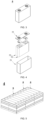
- a hydrogen bond X-H-Y may be formed between the positive binder having the X group and the YH group in the first polar substance in the present application, thereby more firmly binding the first coating and the positive electrode in the present application. More specifically, as shown in FIG. 1 , for example, the positive binder contains F, such that the hydrogen bond is easy to form between the positive binder and the first polar substance (-OH).
- the second coating of the separator is a structure with a preset thickness including the second polar substance, and may be firmly bound to the negative binder and/or the negative active substance by the second polar substance, thus preventing the expansion of the bare cell in the processing process and the cycle expansion rate in the cycle use process.
- the second polar substance such as polyolefin amide, polyolefin imine, polyolefin oxide, polyurethane, polyurea, or the like, includes polar functional groups, and on the one hand, hydrogen bonds may be formed between the polar functional groups and the negative binder and/or the negative active substance to increase a binding force between the second coating and the negative electrode; on the other hand, the second polar substance is a binder, and may also increase the binding force between the second coating and the negative electrode. Therefore, the second coating and the negative electrode are more firmly bound under the two actions of the polar functional group in the second polar substance and the second polar substance which is a binder.
- the second polar substance in the present application has a YH group, and Y is one of N, O and F.
- the negative binder and/or the negative active component have/has a -HX group, and X is one of N, O and F; herein, a hydrogen bond X-H-Y may be formed between the negative binder and/or the negative active component having the X group and the YH group in the second polar substance in the present application, thereby more firmly binding the second coating and the negative electrode in the present application. More specifically, as shown in FIG.
- the negative electrode contains -OH/- COOH; for example, the negative active substance contains -OH, the negative binder contains -COOH, and therefore, the hydrogen bond is also easy to form between the negative active substance or the negative binder and the second polarity substance (containing -NH 2 ).
- the binding forces between the separator and the positive electrode and the negative electrode may be increased by the hydrogen bonds respectively, so as to reduce the expansion of the bare cell in the processing process and the circle expansion rate in the cycle use process, facilitate shaping of the bare cell, and make the bare cell more compact, thereby shortening a transport path of lithium ions, more quickly transporting the lithium ions, and thus making the high-rate discharge performance and the cycle performance of the battery better.
- a peeling force between the first coating and the positive electrode is not lower than 0.075N, optionally 0.075N-0.125N.
- a peeling force between the second coating and the negative electrode is not lower than 0.075N, optionally 0.075N-0.15N.
- the peeling force is a maximum force required to peel a unit width of materials pasted together from a contact surface.
- the peeling force may reflect binding strength of the materials.
- existence and strength of the hydrogen bonds between the separator and the positive electrode and the negative electrode may be macroscopically reflected by the peeling force, so as to reflect the binding force between the separator and the positive electrode and the negative electrode.
- the peeling force between the separator (if the first coating does not contain the first polar substance) and the positive electrode is usually less than 0.035N, and at this point, the separator and the positive electrode have a small binding force, and no or quite few hydrogen bonds exist, but in the present application, after a test of the peeling force between a surface of the positive electrode and the coating of the separator, it is unexpectedly found that the peeling force between the first coating and the positive electrode is not less than 0.075N by adding the first polar substance into the first coating, which may thus further prove that the hydrogen bonds are formed between the first polar substance and the positive binder.
- the peeling force between the separator (if the second coating does not contain the second polar substance) and the negative electrode is also usually less than 0.035N, and at this point, the separator and the negative electrode have a small binding force, and no or quite few hydrogen bonds exist.
- the peeling force between the second coating and the negative electrode is not less than 0.075N by adding the second polar substance into the second coating, which may further prove that the hydrogen bonds are formed between the second polar substance and the negative binder or the negative active component.
- the peeling force between the first coating and the positive electrode or the peeling force between the second coating and the negative electrode is not less than 0.075N
- the bare cell is not prone to expansion in the processing process and the cycle use process, and the separator is in closer contact with the positive electrode and the negative electrode, which shortens the transport path of the lithium ions, such that the lithium ions may be transported more quickly, resulting in the better high-rate discharge performance and cycle performance of the battery.
- a mass content w 1 of the first polar substance in the first coating and a mass content m 1 of the positive binder in a positive film layer may have a ratio w 1 m 1 of (80-100):1.
- w 1 m 1 may reflect a relative content relationship between the first polar substance and the positive binder in the separator.
- w 1 m 1 is less than 80:1
- the first polar substance has an insufficient binding force, such that the first coating and the positive binder cannot be bound firmly, and thus, the expansion problem of the bare cell in the processing process and the cycle process cannot be well solved.
- an electron transport channel may be blocked by the positive binder with an excessively high content, and furthermore, the positive binder is usually an inert insulator and has poor conductivity and large polarization, thus influencing the cycle performance and the high-rate discharge performance of the battery.
- w 1 m 1 is greater than 100:1
- the base film is prone to blockage, thus reducing air permeability and affecting a dynamic performance of the separator; second, the first polar substance is prone to fall from the base film in the middle and later periods of a cycle, thus deteriorating the cycle performance and the high-rate discharge performance.
- the positive binder with an excessively low content may cause insufficient viscosity, and therefore, the positive electrode and the first coating have a small binding force.
- a numerical value of w 1 m 1 within the reasonable range may reduce the expansion of the bare cell in the processing process and the cycle use process, and improve the high-rate discharge performance and the cycle performance of the battery.
- the mass content w 1 of the first polar substance in the first coating and the mass content m 1 of the positive binder in the positive film layer have a ratio w 1 m 1 of 80:1, 87:1, 93:1, 97:1, 100:1, or the like.
- w 1 m 1 may be any above-mentioned point value or any range of values between the point values.
- a mass content w 2 of the second polar substance in the second coating and a mass content m 2 of the negative binder in a negative film layer may have a ratio w 2 m 2 of (32-50):1.
- w 2 m 2 may reflect a relative content relationship between the second polar substance and the negative binder in the separator.
- w 2 m 2 is less than 32:1
- the second polar substance has an insufficient binding force, such that the second coating and the negative binder cannot be bound firmly, and thus, the expansion problem of the bare cell in the processing process and the cycle process cannot be well solved.
- an electron transport channel may be blocked by the negative binder with an excessively high content, and furthermore, the negative binder is usually an inert insulator and has poor conductivity and large polarization, thus influencing the cycle performance and the high-rate discharge performance of the battery.
- the negative binder with an excessively low content may cause insufficient viscosity, and therefore, the negative electrode and the second coating have a small binding force.
- a numerical value of w 2 m 2 within the reasonable range may reduce the expansion of the bare cell in the processing process and the cycle process, and improve the high-rate discharge performance and the cycle performance of the battery.
- the mass content w 2 of the second polar substance in the second coating and the mass content m 2 of the negative binder in the negative film layer may have a ratio w 2 m 2 of 32:1, 36:1, 40:1, 45:1, 50:1, or the like.
- w2 m2 may be any above-mentioned point value or any range of values between the point values.
- the mass content w 1 of the first polar substance in the first coating and the mass content w 2 of the second polar substance in the second coating may have a ratio w 1 w 2 of 1:(1-1.3).
- w 1 w 2 may reflect contents of the polar substances with which two surfaces of the separator are coated.
- the separator may have consistent tension and be more stable, which may, on the one hand, prevent a short circuit risk caused by inconsistent tension, and on the other hand, improve the cycle performance and the high-rate discharge performance of the battery. If w 1 w 2 is less than 1: 1 or w 1 w 2 is greater than 1: 1.3, two surfaces of the separator have inconsistent tension, the separator is wrinkled, bubbles are generated on the surface, immersion by the electrolyte is not good, lithium is prone to precipitation, the cycle performance is deteriorated, cycle attenuation is accelerated, and the high-rate discharge performance is deteriorated.
- the mass content w 1 of the first polar substance in the first coating and the mass content w 2 of the second polar substance in the second coating have a ratio w 1 w 2 of 1:1, 1:1.3, or the like.
- w 1 w 2 may be any above-mentioned point value or any range of values between the point values.
- the first polar substance may have a mass content w 1 of 80%-90% in the first coating.
- w 1 may reflect the content of the first polar substance in the first coating.
- the first polar substance accounts for a main part in the first coating, which may increase the hydrogen bonds between the first polar substance and the positive binder, such that the first coating and the positive electrode have a better binding force. If the first polar substance has a content lower than 80% in the first coating and few hydrogen bonds are generated between the first polar substance and the positive binder, a binding performance between the separator and the positive electrode is improved limitedly, and an expansion improvement effect of the bare cell in the processing process and the cycle use process is not obvious; if the first polar substance has a content higher than 90% in the first coating, the base film is prone to blockage, thus reducing the air permeability and influencing the dynamic performance of the separator.
- the first polar substance has a mass content w 1 of 80%, 85%, 90%, or the like, in the first coating.
- W 1 may be any above-mentioned point value or any range of values between the point values.
- the positive binder may have a mass content m 1 of 0.9%-1.2% in the positive film layer.
- m 1 may reflect the content of the positive binder in the positive film layer.
- the positive electrode and the first coating may be bound firmly, thereby reducing the expansion of the bare cell in the processing process or the cycle use process, and improving the high-rate discharge performance and the cycle performance of the battery.
- the positive binder cannot have an excessively large content in a positive plate, and when m 1 is greater than 1.2%, the electron transport channel may be blocked by the positive binder with an excessively high content, and in addition, the positive binder is usually an inert insulator and has poor conductivity and large polarization, thus influencing the cycle performance and the high-rate discharge performance of the battery.
- the positive binder also cannot have an excessively small content in the positive plate, and when m 1 is less than 0.9%, the positive binder with an excessively low content may cause insufficient viscosity, and therefore, the positive electrode and the first coating have a small binding force.
- the positive binder may have a mass content m 1 of 0.9%, 1%, 1.2%, or the like, in the positive film layer.
- M 1 may be any above-mentioned point value or any range of values between the point values.
- the dynamic performance and the binding force between the first coating and the positive electrode may be considered, and an optimal ratio therebetween may be obtained, thus improving the high-rate discharge performance and the cycle performance of the battery.
- the second polar substance may have a mass content w 2 of 80%-90% in the second coating.
- w 2 may reflect the content of the second polar substance in the second coating.
- the second polar substance accounts for a main part in the second coating, which may increase the hydrogen bonds between the second polar substance and the negative binder, such that the second coating and the negative electrode have a better binding force. If the second polar substance has a content lower than 80% in the second coating and few hydrogen bonds are generated between the second polar substance and the negative binder, a binding performance between the separator and the negative electrode is improved limitedly, and an expansion improvement effect of the bare cell in the processing process and the cycle use process is not obvious; if the second polar substance has a content higher than 90% in the second coating, the base film is prone to blockage, thus reducing the air permeability and influencing the dynamic performance of the separator.
- the second polar substance has a mass content w 2 of 80%, 85%, 90%, or the like, in the second coating.
- w 2 may be any above-mentioned point value or any range of values between the point values.
- the negative binder may have a mass content m 2 of 2%-3% in the negative film layer.
- m 2 may reflect the content of the negative binder in the negative film layer.
- the negative electrode and the second coating may be bound firmly, thereby reducing the expansion of the bare cell in the processing process or the cycle use process, and improving the high-rate discharge performance and the cycle performance of the battery.
- the negative binder cannot have an excessively large content in a negative plate, and when m 1 is greater than 3%, the electron transport channel may be blocked by the negative binder with an excessively high content, and in addition, the negative binder is usually an inert insulator and has poor conductivity and large polarization, thus influencing the cycle performance and the high-rate discharge performance of the battery.
- the negative binder also cannot have an excessively small content in the negative plate, and when m 1 is less than 2%, the negative binder with an excessively low content may cause insufficient viscosity, and therefore, the negative electrode and the second coating have a small binding force.
- the negative binder may have a mass content m 2 of 2%, 2.6%, 3%, or the like, in the negative film layer.
- m 2 may be any above-mentioned point value or any range of values between the point values.
- the dynamic performance and the binding force between the second coating and the negative electrode may be considered, and an optimal ratio therebetween may be obtained, thus improving the high-rate discharge performance and the cycle performance of the battery.
- the first polar substance includes polyethylene oxide and polyacrylamide.
- the polyethylene oxide and the polyacrylamide may have a mass ratio C1 of (2-6):1.
- the polyethylene oxide is a lithium ion conductor, has characteristics of high conductivity, low activation energy, most negative electrode potential, or the like, may accelerate conduction of the lithium ions, and is required to account for a main part in the first polar substance.
- the polyacrylamide has a large chain length, a large molecular weight, and good thermal stability compared with the polyethylene oxide (PEO), and a surface connected with the positive electrode is usually oxidized at a high pressure, mixture of a small number of long chain molecules, such as the polyacrylamide, or the like, in the polyethylene oxide, particularly within the range defined in the present application, may improve cycle stability and the high-rate discharge performance of the battery.
- PEO polyethylene oxide
- the polyethylene oxide and the polyacrylamide have a mass ratio C1 less than 2:1, since the polyacrylamide is not a lithium ion conductor, a lithium ion conduction rate is low, thus influencing the cycle performance and the high-rate discharge performance of the battery. If the polyethylene oxide and the polyacrylamide have a mass ratio C1 greater than 6:1, the polyacrylamide has an excessively low content, resulting in poor thermal stability.
- the polyethylene oxide and the polyacrylamide may have a mass ratio C1 of 2:1, 3:1, 4.5:1, 5:1, 6:1, or the like.
- C1 may be any above-mentioned point value or any range of values between the point values.
- the second polar substance includes polyethylene imine and polyethylene oxide.
- the polyethylene imine and the polyethylene oxide may have a mass ratio C2 of (2-6):1.
- both the polyethylene imine and the polyethylene oxide are lithium ion conductors, have characteristics of high conductivity, low activation energy, most negative electrode potential, or the like, and may accelerate conduction of the lithium ions.
- the second active substance is located on a side connected with the negative electrode, and since the negative active substance, such as graphite, is prone to expansion, a binder with high polarity, such as polyethylene imine (PEI) is required to be selected; in addition, since polyethylene oxide is cheaper than polyethylene imine, a small amount of polyethylene oxide may be added into polyethylene imine in consideration of a cost factor, particularly within the range defined by the present application, such that the hydrogen bonds may be formed between the polyethylene oxide and the polyethylene imine while the cost is reduced, thus further increasing the binding force, reducing the expansion of the bare cell in the processing and cycle use processes, and improving the cycle performance and the high-rate discharge performance of the battery.
- PEI polyethylene imine
- the polyethylene imine and the polyethylene oxide have a mass ratio C2 less than 2:1, since the polyethylene imine has high polarity, when the content is excessively low, few hydrogen bonds are formed between the second polar substance and the negative binder or the negative active substance, and the second coating and the negative electrode have a reduced binding force, thus increasing the expansion of the bare cell in the processing process and the cycle use process, and influencing the cycle performance and the high-rate discharge performance of the battery. If the polyethylene imine and the polyethylene oxide have a mass ratio C2 greater than 6:1, a cost is increased.
- the polyethylene imine and the polyethylene oxide may have a mass ratio C2 of 2:1, 3:1, 4.5:1, 5:1, 6:1, or the like.
- C2 may be any above-mentioned point value or any range of values between the point values.
- polyamide may be one or a combination of more of polyacrylamide (PAM), nylon-66, nylon-6, or the like, in the first or second polar substance.
- the polyamide may have a weight-average molecular weight of 20,000-80,000, optionally 20,000, 30,000, 40,000, 50,000, 60,000, 70,000, 80,000, or the like, and the weight-average molecular weight of the polyamide may be any above-mentioned point value or any range of values between the point values.
- the polyolefin imine may be one or more of polyethylene imine (PEI), polyethylene polyamine, or the like, in the first or second polar substance.
- PEI polyethylene imine
- the polyolefin imine may have a weight-average molecular weight of 70,000-100,000, optionally 70,000, 80,000, 90,000, 100,000, or the like, and the weight-average molecular weight of the polyolefin imine may be any above-mentioned point value or any range of values between the point values.
- the polyolefin oxide may be polyethylene oxide (PEO), or the like, in the first or second polar substance.
- PEO polyethylene oxide
- the polyolefin oxide may have a weight-average molecular weight of 100,000-200,000, optionally 100,000, 120,000, 140,000, 160,000, 180,000, 200,000, or the like, and the weight-average molecular weight of the polyolefin oxide may be any above-mentioned point value or any range of values between the point values.
- the polyurethane in the first or second polar substance, for example, may be a polymer with a general formula containing - NHCOO-, and more specifically, the polyurethane may be formed by polymerizing at least one monomer of polyisocyanate, toluene diisocyanate (TDI), methylenediphenyl-4,4'-diisocyanate (MDI), polyaryl polym ethylene isocyanate (PAPI), or by copolymerizing two or more monomers, the polymerization including random copolymerization, block copolymerization, or the like.
- TDI toluene diisocyanate
- MDI methylenediphenyl-4,4'-diisocyanate
- PAPI polyaryl polym ethylene isocyanate
- the polyurethane may have a weight-average molecular weight of 1,000-10,000, optionally 1,000, 5,000, 10,000, or the like, and the weight-average molecular weight of the polyurethane may be any above-mentioned point value or any range of values between the point values.
- the polyurea in the first or second polar substance, may be, for example, a polymer with a general formula containing -NHCONH-, and more specifically, may be one or more of polyurea, urea-formaldehyde resin, or the like.
- the polyurea may have a weight-average molecular weight of 5,000-50,000, optionally 5,000, 10,000, 20,000, 30,000, 40,000, 50,000, or the like, and the weight-average molecular weight of the polyurea may be any above-mentioned point value or any range of values between the point values.
- the first coating includes a first reinforcing agent, and the mass content w 1 of the first polar substance in the first coating and a mass content k 1 of the first reinforcing agent in the first coating may have a mass ratio w 1 k 1 of (5-9):1.
- w 1 k 1 reflects a content relationship between the first reinforcing agent and the first polar substance.
- the binding force of the first polar substance on the base film may be enhanced by the first reinforcing agent. Only when the ratio of the first polar substance to the first reinforcing agent on the separator is within the reasonable range, the expansion of the bare cell in the processing process and the cycle expansion rate in the cycle use process may be reduced, and the cycle performance and the high-rate discharge performance of the battery may be improved.
- the first polar substance When w 1 k 1 is greater than 9:1, the first polar substance has an excessively high content, first, the base film is prone to blockage, thus reducing air permeability and affecting the dynamic performance of the separator; second, the first polar substance is prone to fall from the base film in the middle and later periods of the cycle, thus deteriorating the cycle performance and the high-rate discharge performance.
- the first polar substance When w 1 k 1 is less than 5:1, the first polar substance has an excessively low content in the first coating, and thus, few hydrogen bonds are formed between the first polar substance and the positive binder, and the first polar substance has an insufficient binding force, such that the first coating and the positive binder cannot be bound firmly, and thus, the expansion problem of the bare cell in the processing process and the cycle use process cannot be well solved.
- the first polar substance may stably exist on the separator by the first reinforcing agent, thereby reducing the expansion of the bare cell in the processing process and the cycle expansion rate in the cycle use process, and improving the cycle performance and the high-rate discharge performance of the battery.
- the mass content w 1 of the first polar substance in the first coating and the mass content k1 of the first reinforcing agent in the first coating may have a mass ratio w 1 k 1 of 5:1, 5.3:1, 6:1, 8:1, 9:1, or the like.
- w 1 k 1 may be any above-mentioned point value or any range of values between the point values.
- the second coating includes a second reinforcing agent, and the mass content w 2 of the second polar substance in the second coating and a mass content k 2 of the second reinforcing agent in the second coating may have a mass ratio w 2 k 2 of (5-9):1.
- w 2 k 2 reflects a content relationship between the second reinforcing agent and the second polar substance.
- the binding force of the second polar substance on the base film may be enhanced by the second reinforcing agent. Only when the ratio of the second polar substance to the second reinforcing agent on the separator is within the reasonable range, the expansion of the bare cell in the processing process and the cycle expansion rate in the cycle use process may be reduced, and the cycle performance and the high-rate discharge performance of the battery may be improved.
- w 2 k 2 is greater than 9:1, the second polar substance has an excessively high content and is prone to fall in the middle and later periods of the cycle, thus deteriorating the cycle performance and the high-rate discharge performance.
- the second polar substance When w 2 k 2 is less than 5:1, the second polar substance has an excessively low content in the second coating, and thus, few hydrogen bonds are formed between the second polar substance and the negative binder, and the second polar substance has an insufficient binding force, such that the second coating and the negative binder cannot be bound firmly, and thus, the expansion problem of the bare cell in the processing process and the cycle use process cannot be well solved.
- the hydrogen bond Y-H-F is easily formed between the second reinforcing agent (containing F) and the second polar substance (-YH), and the second polar substance may stably exist on the separator by the second reinforcing agent, thereby reducing the expansion of the bare cell in the processing process and the cycle expansion rate in the cycle use process, and improving the cycle performance and the high-rate discharge performance of the battery.
- the mass content w 2 of the second polar substance in the second coating and the mass content k 2 of the second reinforcing agent in the second coating may have a mass ratio w 2 k 2 of 5:1, 5.3:1, 6:1, 8:1, 9:1, or the like.
- w 2 k 2 may be any above-mentioned point value or any range of values between the point values.
- the mass content k 1 of the first reinforcing agent in the first coating is not higher than the mass content k 2 of the second reinforcing agent in the second coating.
- k 1 and k 2 may reflect contents of the reinforcing agents with which the two surfaces of the separator are coated, and k 1 and k 2 cannot be significantly different.
- the tension of the separator may be kept consistent, and the separator is more stable, which may, on the one hand, prevent the short circuit risk caused by inconsistent tension, and on the other hand, improve the cycle performance and the high-rate discharge performance of the battery. If k 1 is significantly different from k 2 , the two surfaces of the separator have inconsistent tension, the separator is wrinkled, bubbles are generated on the surface, immersion by the electrolyte is not good, lithium is prone to precipitation, the cycle performance is deteriorated, cycle attenuation is accelerated, and the high-rate discharge performance is deteriorated.
- the mass content k 1 of the first reinforcing agent in the first coating and the mass content k 2 of the second reinforcing agent in the second coating may have a ratio k 1 k 2 of (0.8-1):1.
- k 1 k 2 may reflect the relative contents of the reinforcing agents on the two surfaces of the separator.
- k 1 k 2 is less than 0.8:1 or k 1 k 2 is greater than 1:1, the two surfaces of the separator have inconsistent tension, the separator is wrinkled, bubbles are generated on the surface, immersion by the electrolyte is not good, lithium is prone to precipitation, the cycle performance is deteriorated, cycle attenuation is accelerated, and the high-rate discharge performance is deteriorated.
- the two surfaces of the separator have basically consistent contents, which may reduce a difference of the two surfaces of the separator.
- the mass content k 1 of the first reinforcing agent in the first coating and the mass content k 2 of the second reinforcing agent in the second coating may have a ratio k 1 k 2 of 0.80:1, 0.9:1, 0.95:1, 1:1, or the like.
- k 1 k 2 may be any above-mentioned point value or any range of values between the point values.
- the first reinforcing agent may have a mass content k 1 of 10%-20% in the first coating.
- the second reinforcing agent may have a mass percentage content k 2 of 10%-20% in the second coating.
- k 1 may reflect the content of the reinforcing agent in the first coating.
- k 2 may reflect the content of the second reinforcing agent in the second coating.
- the content of the first reinforcing agent in the first coating cannot be significantly different from the content of the second reinforcing agent in the second coating; if k 1 is significantly different from k 2 , the two surfaces of the separator have inconsistent tension, the separator is wrinkled, bubbles are generated on the surface, immersion by the electrolyte is not good, lithium is prone to precipitation, the cycle performance is deteriorated, cycle attenuation is accelerated, and the high-rate discharge performance is deteriorated.
- the two surfaces of the separator have basically consistent contents, which may reduce the difference of the two surfaces of the separator; the separator has consistent tension and is prevented from being wrinkled.
- the first reinforcing agent may have a mass content k 1 of 14%, 16.6%, 18%, 19%, 20%, or the like, in the first coating.
- K 1 may be any above-mentioned point value or any range of values between the point values.
- the second reinforcing agent may have a mass percentage content k 2 of 10%, 11%, 14%, 15.8%, 16.6%, 17%, 20%, or the like, in the second coating.
- k 2 may be any above-mentioned point value or any range of values between the point values.
- the first reinforcing agent or the second reinforcing agent includes one or more of polyvinylidene difluoride and sodium alginate; due to a low cost, the polyvinylidene difluoride is preferred.
- the positive binder includes polyvinylidene fluoride.
- the negative binder includes more than one of styrene butadiene rubber and sodium alginate.
- the first or second reinforcing agent has a weight-average molecular weight of 500-600,000, optionally 500, 10,000, 100,000, 200,000, 300,000, 400,000, 500,000, 600,000, or the like, and the weight-average molecular weight of the first or second reinforcing agent may be any above-mentioned point value or any range of values between the point values.
- the polyvinylidene difluoride may have a weight-average molecular weight of 100,000-600,000, optionally 100,000, 200,000, 300,000, 400,000, 500,000, 600,000, or the like, and the weight-average molecular weight of the polyvinylidene difluoride may be any above-mentioned point value or any range of values between the point values.
- the sodium alginate may have a weight-average molecular weight of 500-50,000, optionally 500, 10,000, 20,000, 30,000, 40,000, 50,000, or the like, and the weight-average molecular weight of the sodium alginate may be any above-mentioned point value or any range of values between the point values.
- the polyvinylidene difluoride and the sodium alginate may be applied to the first reinforcing agent, the second reinforcing agent, the positive binder or the negative binder.
- the first coating and the second coating may have a mass ratio of 1:(1-1.5).
- the first coating and the second coating may reflect the contents of the coated substances on the two surfaces of the separator, and the two contents cannot be significantly different; thus, by limiting the coating quantities of the first coating and the second coating within the reasonable ranges, the separator may have consistent tension and is more stable, which may, on the one hand, prevent the short circuit risk caused by inconsistent tension, and on the other hand, improve the cycle performance and the high-rate discharge performance of the battery.
- the two surfaces of the separator have inconsistent tension, the separator is wrinkled, bubbles are generated on the surface, immersion by the electrolyte is not good, lithium is prone to precipitation, the cycle performance is deteriorated, cycle attenuation is accelerated, and the high-rate discharge performance is deteriorated.
- the first coating and the second coating may have a mass ratio of 1:1, 1:2, 1:3, 1:4, 1:5, or the like.
- the mass ratio of the first coating to the second coating may be any above-mentioned point value or any range of values between the point values.
- the first coating or the second coating may further include a filler which may be, for example, alumina, and the filler may improve heat resistance and stability of the coating, and when used in combination with the first polar substance, may reduce the expansion of the bare cell in the processing process and the cycle use process, and improve the cycle performance and the high-rate discharge performance of the battery.
- a content of the filler is not particularly limited; for example, the filler may have a mass proportion greater than 0% and less than or equal to 25% in the first or second coating.
- the filler in the first or second coating with a content greater than 25% may block pores of the base film, thus resulting in a slow ion transport rate and affecting the cycle performance and the high-rate discharge performance of the battery.
- the filler may have a mass percent of 3.2%, 8%, 10%, 15%, 18.9%, 20%, 25%, or the like, in the first or second coating.
- the mass percent of the filler in the first or second coating may be any above-mentioned point value or any range of values between the point values.
- the first coating is prepared from first coating slurry.
- the first coating slurry includes the first polar substance, the first reinforcing agent and a first solvent; the first coating slurry may have viscosity of 8,000mpa.s-12,000mpa.s.
- the first coating slurry may be prepared using a method known in the art.
- the first polar substance and the first reinforcing agent may be mixed in the first solvent to form uniform slurry, i.e., the first coating slurry, and optionally, in the preparation process of the first coating slurry, the first polar substance, the first reinforcing agent and the filler may be mixed and then dissolved in the first solvent to prepare the first coating slurry.
- the first polar substance and the first reinforcing agent may be mixed in the first solvent to form uniform slurry, i.e., the first coating slurry, and optionally, in the preparation process of the first coating slurry, the first polar substance, the first reinforcing agent and the filler may be mixed and then dissolved in the first solvent to prepare the first coating slurry.
- viscosity of the first coating slurry greatly influences coating and an electrochemical performance of the cell, and if the first coating slurry has excessively high viscosity, gel is prone to formation, and coating is uneven, resulting in poor consistency of the cell and reduction of the cycle performance and the high-rate discharge performance of the battery. If the first coating slurry has excessively low viscosity, the base film cannot be well coated with the first coating slurry. Thus, by limiting the viscosity of the first coating slurry within the proper range, the base film may be well coated with the first coating slurry, the consistency of the cell may be guaranteed to be good, and the cycle performance and the high-rate discharge performance of the battery may be improved.
- the first coating slurry may have viscosity of 8,000mpa.s, 9,000mpa.s, 10,000mpa.s, 11,000mpa.s, 12,000mpa.s, or the like.
- a weight-average molecular weight of the first coating slurry may be any above-mentioned point value or any range of values between the point values.
- the first solvent is usually not limited, and more specifically, when the first reinforcing agent is sodium alginate, selection of the first solvent is not limited.
- the first solvent is an organic solvent which may be, for example, N,N-dimethyl pyrrolidone, acetone, or the like.
- the second coating is prepared from second coating slurry, and the second coating may be prepared using a method known in the art.
- the second coating slurry includes the second polar substance, the second reinforcing agent and a second solvent; the second coating slurry has viscosity of 5,000mpa.s-20,000mpa.s.
- the second coating slurry may be prepared using a method known in the art.
- the second polar substance and the second reinforcing agent may be mixed in the second solvent to form uniform slurry, i.e., the second coating slurry, and optionally, in the preparation process of the second coating slurry, the second polar substance, the second reinforcing agent and the filler may be mixed and then dissolved in the second solvent to prepare the second coating slurry.
- the second polar substance and the second reinforcing agent and the filler may be mixed and then dissolved in the second solvent to prepare the second coating slurry.
- viscosity of the second coating slurry greatly influences coating and an electrochemical performance of the cell, and if the second coating slurry has excessively high viscosity, gel is prone to formation, and coating is uneven, resulting in poor consistency of the cell and reduction of the cycle performance and the high-rate discharge performance of the battery. If the second coating slurry has excessively low viscosity, the base film cannot be well coated with the second coating slurry. Thus, by limiting the viscosity of the second coating slurry within the proper range, the base film may be well coated with the second coating slurry, the consistency of the cell may be guaranteed to be good, and the cycle performance and the high-rate discharge performance of the battery may be improved.
- the second coating slurry may have viscosity of 5,000mpa.s, 8,000mpa.s, 10,000mpa.s, 13,000mpa.s, 15,000mpa.s, 18,000mpa.s, 20,000mpa.s, or the like.
- a weight-average molecular weight of the second coating slurry may be any above-mentioned point value or any range of values between the point values.
- the second solvent is usually not limited, and more specifically, when the second reinforcing agent is sodium alginate, selection of the second solvent is not limited.
- the second solvent is an organic solvent which may be, for example, N,N-dimethyl pyrrolidone, acetone, or the like.
- a type of the base film is not particularly limited in the present application, and any well-known base film with a porous structure having good chemical stability and mechanical stability may be selected.
- the base film may be made of at least one of glass fibers, non-woven fabrics, polyethylene, polypropylene and polyvinylidene difluoride.
- the base film may be a single-layer film or a multi-layer composite film, which is not particularly limited.
- respective layers may be made of same or different materials, which is not particularly limited.
- the negative electrode includes a negative current collector and a negative film layer provided on at least one surface of the negative current collector, the negative film layer including a negative active component.
- the negative active component includes a silicon-carbon mixture, and silicon in the silicon-carbon mixture may have a particle size of 0.1-0.5 microns.
- Carbon is mixed carbon of artificial graphite and natural graphite.
- the particle size of the silicon greatly influences an electrochemical performance
- micron silicon has a smaller specific surface area and fewer side reactions than nanometer silicon
- the battery has the better cycle performance and high-rate discharge performance, and therefore, micron silicon is selected.
- the silicon has a particle size of 0.1 microns, 0.3 microns, 0.5 microns, or the like.
- the particle size of the silicon may be any above-mentioned point value or any range of values between the point values.
- the silicon-carbon mixture may have C:Si of 95-97: 3-5, or the like. More specifically, C:Si may be 95:5.
- the silicon-carbon mixture may have a content of 95%-97% in the negative film layer. Since the content of the silicon-carbon mixture affects an energy density of the cell, a high capacity of the battery may be realized only when the silicon-carbon mixture has a content greater than 95% in the negative film layer, so as to improve the cycle performance and the high-rate discharge performance of the battery.
- the silicon-carbon mixture may have a content of 95.9%, 96%, 96.7%, 96.8%, 97%, or the like, in the negative film layer.
- the content of the silicon-carbon mixture in the negative film layer may be any above-mentioned point value or any range of values between the point values.
- the negative active component may be a negative active material for a battery well known in the art.
- the negative active component may include at least one of the following materials: artificial graphite, natural graphite, soft carbon, hard carbon, silicon-based materials, tin-based materials, lithium titanate, or the like.
- the silicon-based material may be at least one of elemental silicon, a silicon-oxygen compound, a silicon-nitrogen composite, and a silicon alloy.
- the tin-based material may be at least one of elemental tin, a tin-oxide compound, and a tin alloy.
- the present application is not limited to these materials, and other conventional materials which may be used as the negative active component of the battery may be used. Only one of these negative active components may be used, or more than two thereof are used in combination.
- the negative current collector has two surfaces opposite in a thickness direction thereof, and the negative film layer is provided on one or both of the two opposite surfaces of the negative current collector.
- metal foil or a composite current collector may be used as the negative current collector.
- copper foil may be used as the metal foil.
- the composite current collector may include a high molecular material base layer and a metal layer formed on at least one surface of the high molecular material base layer.
- the composite current collector may be formed by forming a metal material (copper, a copper alloy, nickel, a nickel alloy, titanium, a titanium alloy, silver, a silver alloy, or the like) on the base layer of high molecular material (such as polypropylene (PP), polyethylene terephthalate (PET), polybutylene terephthalate (PBT), polystyrene (PS), polyethylene (PE), or the like).
- PP polypropylene
- PET polyethylene terephthalate
- PBT polybutylene terephthalate
- PS polystyrene
- PE polyethylene
- the negative film layer further optionally includes a negative binder.
- the negative binder may be at least one of styrene butadiene rubber (SBR), polyacrylic acid (PAA), sodium polyacrylate (PAAS), polyacrylamide (PAM), polyvinyl alcohol (PVA), sodium alginate (SA), polymethacrylic acid (PMAA), and carboxymethyl chitosan (CMCS).
- SBR styrene butadiene rubber
- PAA polyacrylic acid
- PAAS sodium polyacrylate
- PAM polyacrylamide
- PVA polyvinyl alcohol
- SA sodium alginate
- PMAA polymethacrylic acid
- CMCS carboxymethyl chitosan
- the negative binder is styrene butadiene rubber (SBR) and sodium alginate (SA).
- the negative film layer further optionally includes a conductive agent.
- the conductive agent may be at least one of superconducting carbon, acetylene black, carbon black, Ketjen black, carbon dots, carbon nanotubes, graphene, and carbon nanofibers.
- the negative film layer may further optionally include other additives, such as a thickener (for example, sodium carboxymethyl cellulose (CMC-Na)), or the like.
- a thickener for example, sodium carboxymethyl cellulose (CMC-Na)
- CMC-Na sodium carboxymethyl cellulose
- the negative electrode may be fabricated by: dispersing the above components for fabricating the negative electrode, such as the negative active component, the conductive agent, the binder, and any other component, in a solvent (for example, deionized water) to form negative slurry; and coating the negative current collector with the negative slurry, and performing drying, cold pressing and other processes to obtain the negative electrode.
- a solvent for example, deionized water
- the positive electrode includes a positive current collector and a positive film layer provided on at least one surface of the positive current collector, the positive film layer including a positive material according to the first aspect of the present application.
- the positive material may have a nickel content greater than 0.5, but different positive system bare cells have different expansion changes, and the separator in the present application especially has a remarkable improvement effect on the cycle expansion rate of the bare cell containing a high-nickel positive material.
- the nickel content is, for example, 0.8-0.9, although the unit cell parameters of the positive material have small changes, since the bare cell also has a small final cycle expansion rate, this nickel content is also within the scope claimed by the present application.
- the positive material may be LiNi 0.4 Co 0.4 Mn 0.2 O 2 , LiNi 0.5 Co 0.2 Mn 0.3 O 2 , LiNi 0.6 Co 0.2 Mn 0.2 O 2 , LiNi 0.7 Co 0.2 Mn 0.1 O 2 , LiNi 0.8 Co 0.1 Mn 0.1 O 2 , LiNi 0.9 Co 0.05 Mn 0.05 O 2 , or the like.
- the positive active material may be a positive active material for a battery well known in the art.
- the positive active material may include at least one of the following materials: lithium-contained phosphate of an olivine structure, lithium transition metal oxide and respective modified compounds thereof.
- the present application is not limited to these materials, and other conventional materials which may be used as the positive active material of the battery may be used. Only one of these positive active materials may be used, or more than two thereof are used in combination.
- lithium transition metal oxide may include, but are not limited to, at least one of lithium cobalt oxide (for example, LiCoO 2 ), lithium nickel oxide (for example, LiNiO 2 ), lithium manganese oxide (for example, LiMnO 2 , LiMn 2 O 4 ), lithium nickel cobalt oxide, lithium manganese cobalt oxide, lithium nickel manganese oxide, lithium nickel cobalt manganese oxide (for example, LiNi 1/3 Co 1/3 Mn 1/3 O 2 (also abbreviated as NCM 333 ), LiNi 0.5 Co 0.25 Mn 0.25 O 2 (also abbreviated as NCM 211 ), lithium nickel cobalt aluminum oxide (for example, LiNi 0.85 Co 0.15 Al 0.05 O 2 ), and modified compounds thereof, or the like.
- lithium cobalt oxide for example, LiCoO 2
- lithium nickel oxide for example, LiNiO 2
- lithium manganese oxide for example, LiMnO 2 , LiMn 2 O 4
- lithium nickel cobalt oxide lithium manganese
- lithium-contained phosphate of an olivine structure may include, but are not limited to, at least one of lithium iron phosphate (for example, LiFePO 4 (also abbreviated as LFP)), a composite material of lithium iron phosphate and carbon, lithium manganese phosphate (for example, LiMnPO 4 ), a composite material of lithium manganese phosphate and carbon, lithium iron manganese phosphate, and a composite material of lithium iron manganese phosphate and carbon.
- LiFePO 4 also abbreviated as LFP
- LiMnPO 4 lithium manganese phosphate
- LiMnPO 4 lithium manganese phosphate and carbon
- the positive current collector has two surfaces opposite in a thickness direction thereof, and the positive film layer is provided on one or both of the two opposite surfaces of the positive current collector.
- metal foil or a composite current collector may be used as the positive current collector.
- aluminum foil may be used as the metal foil.
- the composite current collector may include a high molecular material base layer and a metal layer formed on at least one surface of the high molecular material base layer.
- the composite current collector may be formed by forming a metal material (aluminum, an aluminum alloy, nickel, a nickel alloy, titanium, a titanium alloy, silver, a silver alloy, or the like) on the base layer of high molecular material (such as polypropylene (PP), polyethylene terephthalate (PET), polybutylene terephthalate (PBT), polystyrene (PS), polyethylene (PE), or the like).
- PP polypropylene
- PET polyethylene terephthalate
- PBT polybutylene terephthalate
- PS polystyrene
- PE polyethylene
- the positive film layer further optionally includes a positive binder.
- the positive binder may include at least one of polyvinylidene fluoride (PVDF), polytetrafluoroethylene (PTFE), a vinylidene fluoride-tetrafluoroethylene-propylene terpolymer, a vinylidene fluoride-hexafluoropropylene-tetrafluoroethyleneterpolymer, a tetrafluoroethylene-hexafluoropropylene copolymer, and fluorine-contained acrylate resin.
- the positive binder is polyvinylidene fluoride (PVDF).
- the positive film layer further optionally includes a conductive agent.
- the conductive agent may include at least one of superconducting carbon, acetylene black, carbon black, Ketjen black, carbon dots, carbon nanotubes, graphene, and carbon nanofibers.
- the positive electrode may be fabricated by: dispersing the above components for fabricating the positive electrode, such as the positive material, the conductive agent, the binder, and any other component, in a solvent (for example, N-methyl pyrrolidone) to form positive slurry; and coating the positive current collector with the positive slurry, and performing drying, cold pressing and other processes to obtain the positive electrode.
- a solvent for example, N-methyl pyrrolidone
- the electrolyte plays a role of conducting ions between the positive plate and the negative plate.
- a type of the electrolyte is not particularly limited in the present application and may be selected as desired.
- the electrolyte may be in a liquid, gel, or all solid state.
- the electrolyte is an electrolyte solution.
- the electrolyte includes electrolyte salt and a solvent.
- the electrolyte salt may be at least one of lithium hexafluorophosphate, lithium tetrafluoroborate, lithium perchlorate, lithium hexafluoroarsenate, lithium bis-fluorosulfonylimide, lithium bis-trifluoromethanesulfonylimide, lithium trifluoromethanesulfonate, lithium difluorophosphate, lithium difluorooxalato borate, lithium dioxalato borate, lithium difluorobisoxalate phosphate, and lithium tetrafluorooxalato phosphate.
- the solvent may be at least one of ethylene carbonate, propylene carbonate, ethyl methyl carbonate, diethyl carbonate, dimethyl carbonate, dipropyl carbonate, methyl propyl carbonate, ethyl propyl carbonate, butylene carbonate, fluoroethylene carbonate, methyl formate, methyl acetate, ethyl acetate, propyl acetate, methyl propionate, ethyl propionate, propyl propionate, methyl butyrate, ethyl butyrate, 1,4-butyrolactone, sulfolane, dimethyl sulfone, methyl ethyl sulfone, and diethyl sulfone.
- the electrolyte further optionally includes an additive.
- the additive may include a negative film layer forming additive and a positive film layer forming additive, and may further include an additive capable of improving certain performances of the battery, such as an additive for improving an overcharge performance of the battery, an additive for improving a high-temperature or low-temperature performance of the battery, or the like.
- the secondary battery includes a positive electrode, a negative electrode, an electrolyte, and a separator.
- active ions are inserted and extracted back and forth between the positive electrode and the negative electrode.
- the electrolyte plays a role of conducting the ions between the positive electrode and the negative electrode.
- the separator is provided between a positive plate and a negative plate, mainly functions to prevent a short circuit of the positive electrode and the negative electrode, and meanwhile may allow the ions to pass.
- the positive electrode, the negative electrode and the separator may be manufactured into an electrode assembly with a winding process or a lamination process.
- the secondary battery may include an outer package.
- the outer package may be configured to encapsulate the electrode assembly and the electrolyte.
- the outer package of the secondary battery may be a hard shell, such as a hard plastic shell, an aluminum shell, a steel shell, or the like.
- the outer package of the secondary battery may also be a soft package, such as a bag-type soft package.
- the soft package may be made of plastic, such as polypropylene, polybutylene terephthalate, polybutylene succinate, or the like.
- a shape of the secondary battery is not particularly limited in the present application, and may be a cylindrical shape, a square shape, or any other shape.
- FIG. 3 shows a secondary battery 5 of a square structure as an example.
- the outer package may include a housing 51 and a cover plate 53.
- the housing 51 may include a bottom plate and a side plate connected to the bottom plate, and the bottom plate and the side plate enclose an accommodating cavity.
- the housing 51 has an opening communicated with the accommodating cavity, and the cover plate 53 may cover the opening to close the accommodating cavity.
- the positive plate, the negative plate and the separator may form the electrode assembly 52 with a winding process or a lamination process.
- the electrode assembly 52 is encapsulated within the accommodating cavity.
- the electrolyte immerses the electrode assembly 52.
- One or more electrode assemblies 52 may be contained in the secondary battery 5, and those skilled in the art may make a choice according to specific practical requirements.
- the secondary batteries may be assembled into a battery module, one or more secondary batteries may be contained in the battery module, and the specific number may be selected by those skilled in the art according to an application and a capacity of the battery module.
- FIG. 5 shows a battery module 4 as an example.
- a plurality of secondary batteries 5 may be sequentially arranged in the battery module 4 in a length direction of the battery module 4.
- the secondary batteries 5 may be arranged in any other way.
- the plurality of secondary batteries 5 may be further fixed by fasteners.
- the battery module 4 may further include a casing having an accommodating space in which the plurality of secondary batteries 5 are accommodated.
- the above-mentioned battery modules may be further assembled into a battery pack, one or more battery modules may be contained in the battery pack, and the specific number may be selected by those skilled in the art according to an application and a capacity of the battery pack.
- FIGS. 6 and 7 show a battery pack 1 as an example.
- the battery pack 1 may include a battery box and a plurality of battery modules 4 arranged in the battery box.
- the battery box includes an upper box 2 and a lower box 3, and the upper box 2 may cover the lower box 3 to form an enclosed space for accommodating the battery module 4.
- the plurality of battery modules 4 may be arranged in the battery box in any manner.
- the present application further provides an electric device, including at least one of the secondary battery, the battery module and the battery pack according to the present application.
- the secondary battery, the battery module, or the battery pack may be used as a power source or an energy storage unit of the electric device.
- the electric device may include, but is not limited to, a mobile apparatus (for example, a mobile phone, a notebook computer, or the like), an electric vehicle (for example, a battery electric vehicle, a hybrid electric vehicle, a plug-in hybrid electric vehicle, an electric bicycle, an electric scooter, an electric golf cart, an electric truck, or the like), an electric train, a ship, a satellite, an energy storage system, or the like.
- the secondary battery, the battery module, or the battery pack may be selected according to use requirements of the electric device.
- FIG. 8 shows an electric device as an example.
- the electric device is a battery electric vehicle, a hybrid electric vehicle, a plug-in hybrid electric vehicle, or the like.
- a battery pack or a battery module may be used.
- the device may be a mobile phone, a tablet computer, a notebook computer, or the like.
- the device is required to be thin and light, and a secondary battery may be used as the power source thereof.
- a positive active substance LiNi 0.6 Co 0.2 Mn 0.2 O 2 , a positive binder PVDF and conductive carbon were mixed according to a mass ratio of 97:1.07:1.93 and dissolved in NMP, the mixture was stirred for 6h to obtain positive slurry, aluminum foil was coated with the positive slurry, and drying and cold pressing were performed to obtain the positive electrode.
- a mass content w 1 of the first polar substance in the first coating and a mass content m 1 of the positive binder in a positive film layer had a ratio w 1 m 1 of 75:1.
- a mass content w 2 of the second polar substance in the second coating and a mass content m 2 of the negative binder in a negative film layer had a ratio w 2 m 2 of 30:1.
- the positive electrode, the separator and the negative electrode were stacked in sequence, the first coating of the separator being in contact with the positive electrode, and the second coating of the separator being in contact with the negative electrode; and then, the positive electrode, the separator and the negative electrode were wound to obtain a bare cell.
- the bare cell was placed into an aluminum shell, a top cover was welded, and liquid injection, standing at a high temperature, formation, aging and other processes were performed to obtain the lithium ion battery.
- example 1-1 For the fabrication process of the lithium ion battery, reference was overall made to example 1-1 except that the positive active substance LiNi 0.6 Co 0.2 Mn 0.2 O 2 , the positive binder PVDF and the conductive carbon had a mass ratio of 97:1:2, and the negative active substance (carbon-silicon mixture), the negative binder and the carbon nanotubes had a mass ratio of 97:2.5:0.5.
- the mass content w 1 of the first polar substance in the first coating and the mass content m 1 of the positive binder in the positive film layer had a ratio w 1 m 1 of 80:1.
- the mass content w 2 of the second polar substance in the second coating and the mass content m 2 of the negative binder in the negative film layer had a ratio w 2 m 2 of 32:1.
- example 1-1 For the fabrication process of the lithium ion battery, reference was overall made to example 1-1 except that the positive active substance LiNi 0.6 Co 0.2 Mn 0.2 O 2 , the positive binder PVDF and the conductive carbon had a mass ratio of 97:0.91:2.09, and the negative active substance (carbon-silicon mixture), the negative binder and the carbon nanotubes had a mass ratio of 97:2.2:0.8.
- the mass content w 1 of the first polar substance in the first coating and the mass content m 1 of the positive binder in the positive film layer had a ratio w 1 m 1 of 87:1.
- the mass content w 2 of the second polar substance in the second coating and the mass content m 2 of the negative binder in the negative film layer had a ratio w 2 m 2 of 36:1.
- example 1-1 For the fabrication process of the lithium ion battery, reference was overall made to example 1-1 except that the positive active substance LiNi 0.6 Co 0.2 Mn 0.2 O 2 , the positive binder PVDF and the conductive carbon had a mass ratio of 97:0.86:2.14, and the negative active substance (carbon-silicon mixture), the negative binder and the carbon nanotubes had a mass ratio of 97:2:1.
- the mass content w 1 of the first polar substance in the first coating and the mass content m 1 of the positive binder in the positive film layer had a ratio w 1 m 1 of 93:1.
- the mass content w 2 of the second polar substance in the second coating and the mass content m 2 of the negative binder in the negative film layer had a ratio w 2 m 2 of 40:1.
- example 1-1 For the fabrication process of the lithium ion battery, reference was overall made to example 1-1 except that the positive active substance LiNi 0.6 Co 0.2 Mn 0.2 O 2 , the positive binder PVDF and the conductive carbon had a mass ratio of 97:0.82:2.18, and the negative active substance (carbon-silicon mixture), the negative binder and the carbon nanotubes had a mass ratio of 97:1.77:1.23.
- the mass content w 1 of the first polar substance in the first coating and the mass content m 1 of the positive binder in the positive film layer had a ratio w 1 m 1 of 97:1.
- the mass content w 2 of the second polar substance in the second coating and the mass content m 2 of the negative binder in the negative film layer had a ratio w 2 m 2 of 45:1.
- example 1-1 For the fabrication process of the lithium ion battery, reference was overall made to example 1-1 except that the positive active substance LiNi 0.6 Co 0.2 Mn 0.2 O 2 , the positive binder PVDF and the conductive carbon had a mass ratio of 97:0.8:2.2, and the negative active substance (carbon-silicon mixture), the negative binder and the carbon nanotubes had a mass ratio of 97:1.6:1.4.
- the mass content w 1 of the first polar substance in the first coating and the mass content m 1 of the positive binder in the positive film layer had a ratio w 1 m 1 of 100:1.
- the mass content w 2 of the second polar substance in the second coating and the mass content m 2 of the negative binder in the negative film layer had a ratio w 2 m 2 of 50:1.
- example 1-1 For the fabrication process of the lithium ion battery, reference was overall made to example 1-1 except that the positive active substance LiNi 0.6 Co 0.2 Mn 0.2 O 2 , the positive binder PVDF and the conductive carbon were mixed according to a mass ratio of 97:0.76:2.24, and the negative active substance (carbon-silicon mixture), the negative binder and the carbon nanotubes were mixed according to a mass ratio of 97:1.5:1.5.
- the mass content w 1 of the first polar substance in the first coating and the mass content m 1 of the positive binder in the positive film layer had a ratio w 1 m 1 of 105:1.
- the mass content w 2 of the second polar substance in the second coating and the mass content m 2 of the negative binder in the negative film layer had a ratio w 2 m 2 of 53:1.
- a mass content w 1 of the first polar substance in the first coating and a mass content w 2 of the second polar substance in the second coating had a ratio w 1 w 2 of 1:0.8.
- a positive active substance LiNi 0.6 Co 0.2 Mn 0.2 O 2 , a positive binder PVDF and conductive carbon were mixed according to a mass ratio of 97:1:2 and dissolved in NMP, the mixture was stirred for 6h to obtain positive slurry, aluminum foil was coated with the positive slurry, and drying and cold pressing were performed to obtain the positive electrode.
- the positive electrode, the separator and the negative electrode were stacked in sequence, the first coating of the separator being in contact with the positive electrode, and the second coating of the separator being in contact with the negative electrode; and then, the positive electrode, the separator and the negative electrode were wound to obtain a bare cell.
- the bare cell was placed into an aluminum shell, a top cover was welded, and liquid injection, standing at a high temperature, formation, aging and other processes were performed to obtain the lithium ion battery.
- This example was basically same as example 2-1 except that the first polar substance PAM and the alumina had a mass ratio of 85:15, and the second polar substance PEO and the alumina had a mass ratio of 85:15.
- the mass content w 1 of the first polar substance in the first coating and the mass content w 2 of the second polar substance in the second coating had a ratio w 1 w 2 of 1:1.
- example 2-1 For the fabrication process of the lithium ion battery, reference was overall made to example 2-1 except that the first polar substance PAM and the alumina had a mass ratio of 71.1:28.9, and the second polar substance PEO and the alumina had a mass ratio of 92.5:7.5.
- example 2-1 For the fabrication process of the lithium ion battery, reference was overall made to example 2-1 except that the first polar substance PAM and the alumina had a mass ratio of 65:35, and the second polar substance PEO and the alumina had a mass ratio of 97.5:2.5.
- a positive active substance LiNi 0.6 Co 0.2 Mn 0.2 O 2 , a positive binder PVDF and conductive carbon were mixed according to a mass ratio of 97:0.8:2.2 and dissolved in NMP to obtain positive slurry, the positive slurry was stirred for 6h, aluminum foil was coated with the positive slurry, and drying and cold pressing were performed to obtain the positive electrode.
- the positive electrode, the separator and the negative electrode were stacked in sequence, the first coating of the separator being in contact with the positive electrode, and the second coating of the separator being in contact with the negative electrode; and then, the positive electrode, the separator and the negative electrode were wound to obtain a bare cell.
- the bare cell was placed into an aluminum shell, a top cover was welded, and liquid injection, standing at a high temperature, formation, aging and other processes were performed to obtain the lithium ion battery.
- the first polar substance polyurea
- the second polar substance PAM had a mass proportion of 80% in the second coating.
- the positive active substance LiNi 0.6 Co 0.2 Mn 0.2 O 2 , the positive binder PVDF and the conductive carbon had a mass ratio of 97:0.9:2.3.
- the negative active substance carbon-silicon mixture
- the negative binder and the carbon nanotubes had a mass ratio of 97:2:1.
- the first polar substance polyurea
- the second polar substance PAM had a mass proportion of 85% in the second coating.
- the positive active substance LiNi 0.6 Co 0.2 Mn 0.2 O 2 , the positive binder PVDF and the conductive carbon had a mass ratio of 97:1:2.
- the negative active substance carbon-silicon mixture
- the negative binder and the carbon nanotubes had a mass ratio of 97:2.6:0.4.
- the first polar substance polyurea
- the second polar substance PAM had a mass proportion of 90% in the second coating.
- the positive active substance LiNi 0.6 Co 0.2 Mn 0.2 O 2 , the positive binder PVDF and the conductive carbon had a mass ratio of 97:1.2:1.8.
- the negative active substance carbon-silicon mixture
- the negative binder and the carbon nanotubes had a mass ratio of 97:3:0.
- the first polar substance polyurea
- the second polar substance PAM had a mass proportion of 92% in the second coating.
- the positive active substance LiNi 0.6 Co 0.2 Mn 0.2 O 2 , the positive binder PVDF and the conductive carbon had a mass ratio of 97:1.5:0.5.
- the negative active substance carbon-silicon mixture
- the negative binder and the carbon nanotubes had a mass ratio of 96.8:3.2:0.
- a mass content k 1 of the first reinforcing agent in the first coating and a mass content k 2 of the second reinforcing agent in the second coating had a ratio k 1 k 2 of 0.7:1.
- a positive active substance LiNi 0.6 Co 0.2 Mn 0.2 O 2 , a positive binder PVDF and conductive carbon were mixed according to a mass ratio of 97:1:2 and dissolved in NMP, the mixture was stirred for 6h to obtain positive slurry, aluminum foil was coated with the positive slurry, and drying and cold pressing were performed to obtain the positive electrode.
- the positive electrode, the separator and the negative electrode were stacked in sequence, the first coating of the separator being in contact with the positive electrode, and the second coating of the separator being in contact with the negative electrode; and then, the positive electrode, the separator and the negative electrode were wound to obtain a bare cell.
- the bare cell was placed into an aluminum shell, a top cover was welded, and liquid injection, standing at a high temperature, formation, aging and other processes were performed to obtain the lithium ion battery.
- example 4-1 For the fabrication process of the lithium ion battery, reference was overall made to example 4-1 except that the first polar substance PEO, the first reinforcing agent PVDF and the alumina had a mass ratio of 80:16.6:3.4.
- example 4-1 For the fabrication process of the lithium ion battery, reference was overall made to example 4-1 except that the first polar substance PEO, the first reinforcing agent PVDF and the alumina had a mass ratio of 80:18:2.
- example 4-1 For the fabrication process of the lithium ion battery, reference was overall made to example 4-1 except that the first polar substance PEO, the first reinforcing agent PVDF and the alumina had a mass ratio of 80:19:1. The mass content k 1 of the first reinforcing agent in the first coating and the mass content k 2 of the second reinforcing agent in the second coating had a ratio k 1 k 2 of 0.95:1.
- example 4-1 For the fabrication process of the lithium ion battery, reference was overall made to example 4-1 except that the first polar substance PEO and the first reinforcing agent PVDF had a mass ratio of 80:20.
- a mass content w 1 of the first polar substance in the first coating and a mass content k 1 of the first reinforcing agent in the first coating had a mass ratio w 1 k 1 of 4.6:1;
- the second coating includes a second reinforcing agent, and a mass content w 2 of the second polar substance in the second coating and a mass content k 2 of the second reinforcing agent in the second coating had a mass ratio w 2 k 2 of 4.9:1.
- a positive active substance LiNi 0.6 Co 0.2 Mn 0.2 O 2 , a positive binder PVDF and conductive carbon were mixed according to a mass ratio of 97:1:2 and dissolved in NMP, the mixture was stirred for 6h to obtain positive slurry, aluminum foil was coated with the positive slurry, and drying and cold pressing were performed to obtain the positive electrode.
- the positive electrode, the separator and the negative electrode were stacked in sequence, the first coating of the separator being in contact with the positive electrode, and the second coating of the separator being in contact with the negative electrode; and then, the positive electrode, the separator and the negative electrode were wound to obtain a bare cell.
- the bare cell was placed into an aluminum shell, a top cover was welded, and liquid injection, standing at a high temperature, formation, aging and other processes were performed to obtain the lithium ion battery.
- example 5-1 For the fabrication process of the lithium ion battery, reference was overall made to example 5-1 except that the first polar substance PAM, the first reinforcing agent PVDF and the alumina had a mass ratio of 80:16:4. The second polar substance PEO and the second reinforcing agent PVDF had a mass ratio of 83.4:16.6.
- the mass content w 1 of the first polar substance in the first coating and the mass content k 1 of the first reinforcing agent in the first coating had a mass ratio w 1 k 1 of 5:1;
- the mass content w 2 of the second polar substance in the second coating and the mass content k 2 of the second reinforcing agent in the second coating had a mass ratio w 2 k 2 of 5:1.
- example 5-1 For the fabrication process of the lithium ion battery, reference was overall made to example 5-1 except that the first polar substance PAM, the first reinforcing agent PVDF and the alumina had a mass ratio of 80:15:5.
- the mass content w 1 of the first polar substance in the first coating and the mass content k 1 of the first reinforcing agent in the first coating had a mass ratio w 1 k 1 of 5.3:1;
- the mass content w 2 of the second polar substance in the second coating and the mass content k 2 of the second reinforcing agent in the second coating had a mass ratio w 2 k 2 of 5.3:1.
- example 5-1 For the fabrication process of the lithium ion battery, reference was overall made to example 5-1 except that the first polar substance PAM, the first reinforcing agent PVDF and the alumina had a mass ratio of 80:13.3:6.7.
- the second polar substance PEO and the second reinforcing agent PVDF had a mass ratio of 86:14.
- the mass content w 1 of the first polar substance in the first coating and the mass content k 1 of the first reinforcing agent in the first coating had a mass ratio w 1 k 1 of 6:1;
- the mass content w 2 of the second polar substance in the second coating and the mass content k 2 of the second reinforcing agent in the second coating had a mass ratio w 2 k 2 of 6:1.
- example 5-1 For the fabrication process of the lithium ion battery, reference was overall made to example 5-1 except that the first polar substance PAM, the first reinforcing agent PVDF and the alumina had a mass ratio of 80:10:10. The second polar substance PEO and the second reinforcing agent PVDF had a mass ratio of 89:11.
- the mass content w 1 of the first polar substance in the first coating and the mass content k 1 of the first reinforcing agent in the first coating had a mass ratio w 1 k 1 of 8:1;
- the mass content w 2 of the second polar substance in the second coating and the mass content k 2 of the second reinforcing agent in the second coating had a mass ratio w 2 k 2 of 8:1.
- example 5-1 For the fabrication process of the lithium ion battery, reference was overall made to example 5-1 except that the first polar substance PAM, the first reinforcing agent PVDF and the alumina had a mass ratio of 80:8.9:11.1.
- the mass content w 1 of the first polar substance in the first coating and the mass content k 1 of the first reinforcing agent in the first coating had a mass ratio w 1 k 1 of 9:1;
- the second coating includes the second reinforcing agent, and the mass content w 2 of the second polar substance in the second coating and the mass content k 2 of the second reinforcing agent in the second coating had a mass ratio w 2 k 2 of 9:1.
- example 5-1 For the fabrication process of the lithium ion battery, reference was overall made to example 5-1 except that the first polar substance PAM, the first reinforcing agent PVDF and the alumina had a mass ratio of 80:8.6:11.4. The second polar substance PEO and the second reinforcing agent PVDF had a mass ratio of 90.3:9.7.
- the mass content w 1 of the first polar substance in the first coating and the mass content k 1 of the first reinforcing agent in the first coating had a mass ratio w 1 k 1 of 9.3:1;
- the second coating includes the second reinforcing agent, and the mass content w 2 of the second polar substance in the second coating and the mass content k 2 of the second reinforcing agent in the second coating had a mass ratio w 2 k 2 of 9.3:1.
- a positive active substance LiNi 0.6 Co 0.2 Mn 0.2 O 2 , a positive binder PVDF and conductive carbon were mixed according to a mass ratio of 97:1:2 and dissolved in NMP, the mixture was stirred for 6h to obtain positive slurry, aluminum foil was coated with the positive slurry, and drying and cold pressing were performed to obtain the positive electrode.
- the positive electrode, the separator and the negative electrode were stacked in sequence, the first coating of the separator being in contact with the positive electrode, and the second coating of the separator being in contact with the negative electrode; and then, the positive electrode, the separator and the negative electrode were wound to obtain a bare cell.
- the bare cell was placed into an aluminum shell, a top cover was welded, and liquid injection, standing at a high temperature, formation, aging and other processes were performed to obtain the lithium ion battery.
- the negative binder and the carbon nanotubes had a mass ratio of 96.7:2.5:0.8.
- This example was basically same as example 6-1 except that the negative active substance (carbon-silicon mixture (Si had a particle size of 0.3 ⁇ m)), the negative binder and the carbon nanotubes had a mass ratio of 97:2.5:0.5.
- the negative active substance carbon-silicon mixture (Si had a particle size of 0.3 ⁇ m)
- the negative binder and the carbon nanotubes had a mass ratio of 97:2.5:0.5.
- the negative binder and the carbon nanotubes had a mass ratio of 96.8:2.5:0.7.
- example 6-1 For the fabrication process of the lithium ion battery, reference was overall made to example 6-1 except that the negative active substance (carbon-silicon mixture (Si had a particle size of 0.6 ⁇ m)), the negative binder and the carbon nanotubes had a mass ratio of 96:2.5:1.5.
- the negative active substance carbon-silicon mixture (Si had a particle size of 0.6 ⁇ m)
- the negative binder and the carbon nanotubes had a mass ratio of 96:2.5:1.5.
- a positive active substance LiNi 0.4 Co 0.4 Mn 0.2 O 2 , a positive binder PVDF and conductive carbon were mixed according to a mass ratio of 97:1:2 and dissolved in NMP, the mixture was stirred for 6h to obtain positive slurry, aluminum foil was coated with the positive slurry, and drying and cold pressing were performed to obtain the positive electrode.
- the positive electrode, the separator and the negative electrode were stacked in sequence, the first coating of the separator being in contact with the positive electrode, and the second coating of the separator being in contact with the negative electrode; and then, the positive electrode, the separator and the negative electrode were wound to obtain a bare cell.
- the bare cell was placed into an aluminum shell, a top cover was welded, and liquid injection, standing at a high temperature, formation, aging and other processes were performed to obtain the lithium ion battery.
- example 7-1 For the fabrication process of the lithium ion battery, reference was overall made to example 7-1 except that the positive active substance was LiNi 0.5 Co 0.2 Mn 0.3 O 2 .
- example 7-1 For the fabrication process of the lithium ion battery, reference was overall made to example 7-1 except that the positive active substance was LiNi 0.6 Co 0.2 Mn 0.2 O 2 .
- example 7-1 For the fabrication process of the lithium ion battery, reference was overall made to example 7-1 except that the positive active substance was LiNi 0.8 Co 0.1 Mn 0.1 O 2 .
- example 7-1 For the fabrication process of the lithium ion battery, reference was overall made to example 7-1 except that the positive active substance was LiNi 0.9 Co 0.05 Mn 0.05 O 2 .
- a positive active substance LiNi 0.4 Co 0.4 Mn 0.4 O 2 , a positive binder PVDF and conductive carbon were mixed according to a mass ratio of 97:1:2 and dissolved in NMP, the mixture was stirred for 6h to obtain positive slurry, aluminum foil was coated with the positive slurry, and drying and cold pressing were performed to obtain the positive electrode.
- the positive electrode, the separator and the negative electrode were stacked in sequence, the first coating of the separator being in contact with the positive electrode, and the second coating of the separator being in contact with the negative electrode; and then, the positive electrode, the separator and the negative electrode were wound to obtain a bare cell.
- the bare cell was placed into an aluminum shell, a top cover was welded, and liquid injection, standing at a high temperature, formation, aging and other processes were performed to obtain the lithium ion battery.
- example 8-1 For the fabrication process of the lithium ion battery, reference was overall made to example 8-1 except that the PEO and the PAM had a mass ratio of 2:1 in the first polar substance, and the PEI and the PEO had a mass ratio of 2:1 in the second polar substance.
- example 8-1 For the fabrication process of the lithium ion battery, reference was overall made to example 8-1 except that the PEO and the PAM had a mass ratio of 3:1 in the first polar substance, and the PEI and the PEO had a mass ratio of 3:1 in the second polar substance.
- example 8-1 For the fabrication process of the lithium ion battery, reference was overall made to example 8-1 except that the PEO and the PAM had a mass ratio of 4.5:1 in the first polar substance, and the PEI and the PEO had a mass ratio of 4.5:1 in the second polar substance.
- example 8-1 For the fabrication process of the lithium ion battery, reference was overall made to example 8-1 except that the PEO and the PAM had a mass ratio of 5:1 in the first polar substance, and the PEI and the PEO had a mass ratio of 5:1 in the second polar substance.
- example 8-1 For the fabrication process of the lithium ion battery, reference was overall made to example 8-1 except that the PEO and the PAM had a mass ratio of 6:1 in the first polar substance, and the PEI and the PEO had a mass ratio of 6:1 in the second polar substance.
- example 8-1 For the fabrication process of the lithium ion battery, reference was overall made to example 8-1 except that the PEO and the PAM had a mass ratio of 6.3:1 in the first polar substance, and the PEI and the PEO had a mass ratio of 6.3:1 in the second polar substance.
- the separators of an example and a comparative example were cut into test samples having a length of 100mm and a width of 10mm.
- a stainless steel plate with a width of 25mm was taken, double-sided adhesive tape (with a width of 11mm) was pasted, the test sample was pasted to the double-sided adhesive tape on the stainless steel plate, and a press roller of 2,000g was used for rolling back and forth three times (300mm/min) on a surface of the test sample.
- the test sample was bent by 180 degrees, an organic-inorganic mixed layer and the base film of the test sample were manually peeled by 25mm, the test sample was fixed on a testing machine (such as INSTRON 336) to keep the peeling surface and a force line of the testing machine consistent, the testing machine performed continuous peeling at 30mm/min to obtain a peeling force curve, an average value of a stable section was taken as a peeling force F0, and a binding force F between the organic-inorganic mixed layer and a current collector in the test sample was calculated by the following formula.
- F F0/width of test sample (unit of F: N/m).
- the test was performed according to the standard GB/T6040-2002 "Infrared Spectrum Analysis Method" using an IS10 Fourier transform infrared spectrometer of Thermo Nicolet Corporation.
- the positive slurry obtained in the example and the comparative example was subjected to suction filtration to obtain positive powder; the PE base film was coated with the first coating slurry obtained in the example and the comparative example, and the PE base film was removed after suction filtration to obtain first coating powder.
- the positive powder and the first coating powder were mixed and further dried to obtain mixed powder; an infrared test was performed on the mixed powder.
- the infrared test method between the second coating and the negative electrode was same as the above method.
- High-rate discharge capacity the batteries of all the examples and comparative examples were subjected to constant-current and constant-voltage charging at a charging current of 1/3C in a 25°C environment until an upper limit voltage was 4.35V. Then, constant-current discharge was performed at discharge currents of 1/3C, 3C and 5C until the final voltage was 2.8V, and a discharge capacity value at this point was recorded.
- Test results of related parameters and performances of the batteries of the above Examples 1-1 to 1-7 are shown in Table 1 below.
- Table 1 Test results of parameters and performances of Examples 1-1 to 1-7 Separator, positive electrode and negative electrode Battery performance First coating and positive electrode Second coating and negative electrode First polar substanc e w 1 Positiv e binder m 1 w 1 m 1 Peelin 9 force (N) Second polar substanc e w 2 Negativ e binder m 2 w 2 m 2 Peelin 9 force (N) w 1 w 2 Cycle expansio n rate Capacity conservati on rate after 1,000 cycles 5C discharg e capacity (Ah) S1 -1 PEO 80 % PVDF 1.07 % 75:1 0.075 PEI 80 % SA+SB R 2.66 % 30: 1 0.085 1:0.9 4 1.7% 81.2% 153.1 S1 -2 PEO 80 % PVDF 1% 80:1 0.085 PEI 80 % SA+SB R 2.5% 32: 1
- Test results of related parameters and performances of the batteries of the above Examples 2-1 to 2-4 are shown in Table 2 below. Table 2.
- Test results of parameters and performances of Examples 2-1 to 2-4 Separator, positive electrode and negative electrode Battery performance First coating and positive electrode Second coating and negative electrode First polar substanc e w 1 Positiv e binder m 1 w 1 m 1 Peelin 9 force (N) Second polar substanc e w 2 Negativ e binder m 2 w 2 m 2 Peelin 9 force (N) w 1 w 2 Cycle expansio n rate Capacity conservati on rate after 1,000 cycles 5C discharg e capacity (Ah) S2 -1 PAM 96.8 % PVDF 1 % 96.8: 1 0.076 PEO 77.5 % SA+SB R 2.5 % 31: 1 0.075 1:0.
- Test results of related parameters and performances of the batteries of the above Examples 3-1 to 3-5 are shown in Table 3 below. Table 3.
- Test results of parameters and performances of Examples 3-1 to 3-5 Separator, positive electrode and negative electrode Battery performance First coating and positive electrode Second coating and negative electrode First polar substanc e w 1 Positiv e binder m 1 w 1 m 1 Peelin 9 force (N) Second polar substanc e w 2 Negativ e binder m 2 w 2 m 2 Peelin 9 force (N) w 1 w 2 Cycle expansio n rate Capacity conservatio n rate after 1,000 cycles 5C discharg e capacity (Ah) S3 -1 Polyurea 75 % PVDF 0.8 % 93.7: 1 0.075 PAM 75 % SA+SB R 1.8 % 41.6: 1 0.078 1: 1 1.8% 78.2% 148.3 S3 -2 Polyurea 80 % PVDF 0.9 % 88.8: 1 0.078 PAM 80
- w 1 m 1 and w 2 m 2 reflect influences of the relative content relationship between the first polar substance and the positive binder and the relative content relationship between the second polar substance and the negative binder in the separator on the battery performance.
- good results of the battery performances such as the cycle expansion rate, the capacity conservation rate after 1,000 cycles and the 5C discharge capacity, are obtained by adjusting w 1 m 1 and w 2 m 2 , and particularly when w 1 m 1 is (80-100):1 and w 2 m 2 is (32-50):1, the battery performance is better.
- w 1 w 2 reflects influences of a ratio of the relative content of the first polar substance in the first coating to the relative content of the second polar substance in the second coating in the separator on the battery performance.
- good results of the battery performances such as the cycle expansion rate, the capacity conservation rate after 1,000 cycles and the 5C discharge capacity, are obtained by adjusting w 1 w 2 , and particularly when w 1 w 2 is 1:(1-1.3), the battery performance is better.
- Examples 6-1 to 6-5 reflect influences of the particle size of silicon on the battery performance. Good results of the battery performances, such as the cycle expansion rate, the capacity conservation rate after 1,000 cycles and the 5C discharge capacity, are obtained, and particularly when the particle size of silicon ranges from 0.1 microns to 0.5 microns, the battery performance is better.
- the expansion of the bare cell may be significantly improved by adjusting the content of Ni in the ternary positive material, good results of the battery performances, such as the cycle expansion rate and the capacity conservation rate after 1,000 cycles, are obtained, and particularly the Ni content ranges from 0.5 to 0.9, the battery performance is better.
- the first polar substance is PEO
- the first reinforcing agent is PVDF
- the positive binder is PEO
- the second polar substance is PEI
- the second reinforcing agent is PVDF
- the negative binders are SA and SBR
- the negative active substance is a carbon-silicon mixture.
- H on -OH in the carbon-silicon mixture is more electron-deficient than H of - NH 2 , and therefore, the hydrogen bond is easily formed between N on -NH 2 in the second polar substance PEI and H on -OH in the carbon-silicon mixture.
- a hydrogen bond is formed between N on -NH 2 in the second polar substance PEI and H on -COOH in the negative binder SA.
- a hydrogen bond may be formed between H on -OH in the carbon-silicon mixture and H on - COOH in SA.
- a peak of the hydrogen bond exists between 3,200cm -1 and 3,600cm -1 , and when the first polar substance or the second polar substance is not added in Comparative Example 1, the hydrogen bond is hardly generated, but in Example 1, the peak is broad and obvious due to hydrogen bond connection on the surfaces A and B.
Landscapes
- Chemical & Material Sciences (AREA)
- Chemical Kinetics & Catalysis (AREA)
- Electrochemistry (AREA)
- General Chemical & Material Sciences (AREA)
- Engineering & Computer Science (AREA)
- Inorganic Chemistry (AREA)
- Composite Materials (AREA)
- Manufacturing & Machinery (AREA)
- Materials Engineering (AREA)
- Battery Electrode And Active Subsutance (AREA)
- Secondary Cells (AREA)
- Cell Separators (AREA)
Abstract
Description
- The present application relates to the field of lithium battery technologies, and particularly to a battery, a battery module, a battery pack and an electric device.
- In recent years, as lithium ion batteries have a more and more extensive application range, the lithium ion batteries are widely applied to energy storage power systems, such as hydraulic power stations, thermal power stations, wind power stations, solar power stations, or the like, and to a plurality of fields, such as electric tools, electric bicycles, electric motorcycles, electric automobiles, military equipment, aerospace, or the like. Due to a great development of the lithium ion battery, higher requirements are also put forward for an energy density, a group margin, a cycle/rate performance, a safety performance, or the like, of the lithium ion battery.
- In addition, a separator is one of components of the battery, and may effectively prevent an internal short circuit caused by contact between a positive electrode and a negative electrode. However, the traditional separator is not connected with the positive electrode or the negative electrode by hydrogen bonds, and is only in physical contact with the positive electrode or the negative electrode, such that a bare cell is prone to expansion, which does not facilitate shaping of the cell. Therefore, the existing battery still needs to be improved.
- The present application is made in view of the above problem, and an object thereof is to provide a battery to further improve an overall performance (high-rate discharge performance and cycle performance) of the battery.
- In order to achieve the above object, the present application provides a battery, a battery module, a battery pack and an electric device.
- A first aspect of the present application provides a battery, including: a positive electrode, a separator and a negative electrode, wherein the separator includes a base film, a first coating provided on a first surface of the base film, and a second coating provided on a second surface of the base film, the first coating includes a first polar substance, the first polar substance includes one or more of polyolefin amide substances, polyolefin imine substances, polyolefin oxide substances, polyurethane substances and polyurea substances, and hydrogen bonds are formed between the first polar substance and a positive binder of the positive electrode; the second coating includes a second polar substance, the second polar substance includes one or more of polyolefin amide substances, polyolefin imine substances, polyolefin oxide substances, polyurethane substances and polyurea substances, and hydrogen bonds are formed between the second polar substance and a negative binder and/or a negative active component of the negative electrode.
- In the present application, the hydrogen bond may be represented by X-H-Y, and X and Y may be one independently selected from N, O and F. The hydrogen bond is easy to form between the positive binder (containing -X) and the first polar substance (containing -YH); similarly, the hydrogen bond is also easy to form between the negative binder and/or the negative active component (containing -HX) and the second polar substance (containing -YH). Therefore, in the present application, binding forces between the separator and the positive electrode and the negative electrode are increased by the hydrogen bonds, thus reducing expansion of a bare cell in a processing process and a cycle expansion rate after several cycles, improving a high-rate discharge capacity of the battery, shortening a lithium ion transport path, and improving a cycle performance of the battery.
- In any embodiment, a peeling force between the first coating and the positive electrode is not lower than 0.075N, optionally 0.075N-0.125N; a peeling force between the second coating and the negative electrode is not lower than 0.075N, optionally 0.075N-0.15N. Thus, the binding forces between the separator and the positive electrode and the negative electrode may be characterized by the peeling forces. When the peeling force is within the reasonable range, the bare cell is not prone to expansion in the processing process and a cycle process, the separator is in close contact with the positive electrode and the negative electrode, and the battery has a strong high-rate discharge capability.
- In any embodiment, a mass content w1 of the first polar substance in the first coating and a mass content m1 of the positive binder in a positive film layer have a ratio


- In any embodiment, the mass content w1 of the first polar substance in the first coating and the mass content w2 of the second polar substance in the second coating have a ratio


- In any embodiment, the first polar substance has a mass content w1 of 80%-90% in the first coating, and the positive binder has a mass content m1 of 0.9%-1.2% in the positive film layer. The second polar substance has a mass content w2 of 80%-90% in the second coating, and the negative binder has a mass content m2 of 2%-3% in the negative film layer. Thus, the battery has both the good high-rate discharge performance and cycle performance by limiting the above parameters within the reasonable ranges.
- In any embodiment, the first polar substance includes polyethylene oxide and polyacrylamide; the polyethylene oxide and the polyacrylamide have a mass ratio C1 of (2-6): 1. The second polar substance includes polyethylene imine and polyethylene oxide; the polyethylene imine and the polyethylene oxide have a mass ratio C2 of (2-6): 1. Thus, in the first polar substance, a small number of polyacrylamide long-chain molecules are mixed in the polyethylene oxide, thus improving cycle stability of the battery. In the second polar substance, a small amount of low-cost polyethylene oxide is added into the polyethylene imine with high polarity, and hydrogen bonds are also formed between the polyethylene imine and the polyethylene oxide, which further increases a binding force in the second polar substance, thereby further improving the high-rate discharge performance and the cycle performance of the battery.
- In any embodiment, the first coating includes a first reinforcing agent, and the mass content w1 of the first polar substance in the first coating and a mass content k1 of the first reinforcing agent in the first coating have a mass ratio


- In any embodiment, the mass content k1 of the first reinforcing agent in the first coating is not higher than the mass content k2 of the second reinforcing agent in the second coating. Thus, by limiting

- In any embodiment, the mass content k1 of the first reinforcing agent in the first coating and the mass content k2 of the second reinforcing agent in the second coating have a ratio

- In any embodiment, the first reinforcing agent or the second reinforcing agent includes one or more of polyvinylidene difluoride and sodium alginate. The positive binder includes polyvinylidene fluoride, and the negative binder includes more than one of styrene butadiene rubber and sodium alginate.
- In any embodiment, the negative active component includes a silicon-carbon mixture, silicon in the silicon-carbon mixture has a particle size of 0.1-0.5 microns, carbon in the silicon-carbon mixture is mixed carbon of artificial graphite and natural graphite, and the silicon-carbon mixture has a content of 95%-97% in the negative film layer. Thus, the cycle performance of the battery may be better by limiting the particle size of the silicon within the reasonable range, and the high-rate charging-discharging performance of the battery may be achieved by limiting the content of the silicon-carbon mixture in the negative film layer within the reasonable range.
- In any embodiment, the first coating and the second coating have a mass ratio of 1:(1-1.5). Thus, by limiting coating quantities of the first coating and the second coating within reasonable ranges, the tension of the separator may be consistent to prevent the risk of the short circuit caused by inconsistent tension, and the cycle performance of the battery may be improved.
- In any embodiment, the first coating is prepared from first coating slurry, and the first coating slurry includes the first polar substance, the first reinforcing agent and a first solvent; the first coating slurry has viscosity of 8,000mpa.s-12,000mpa.s. The second coating is prepared from second coating slurry, and the second coating slurry includes the second polar substance, the second reinforcing agent and a second solvent; the second coating slurry has viscosity of 5,000mpa.s-20,000mpa.s. Thus, by limiting the viscosity of the first coating slurry and the viscosity of the second coating slurry within the proper ranges respectively, a coating process of the first coating slurry or the second coating slurry on the base film may be optimized, a coating effect may be improved, consistency of the cell may be guaranteed to be good, and the cycle performance and the high-rate discharge performance of the battery may be improved.
- In any embodiment, the positive electrode includes a positive material LiNixCoyMnzO2, where x+y+z=1, and x=0.5-0.9, optionally, x=0.5-0.7 or x=0.8-0.9. The separator in the present application especially has a remarkable improvement effect on the cycle expansion rate of the bare cell containing a high-nickel positive material, and especially, the separator in the present application more remarkably improves the cycle expansion rate of the bare cell containing the positive material with a nickel content x=0.5-0.7, and therefore more remarkably improves the high-rate discharge performance and the cycle performance of a high nickel battery.
- A second aspect of the present application provides a battery module, including the battery according to the first aspect of the present application.
- A third aspect of the present application provides a battery pack, including the battery module according to the second aspect of the present application.
- A fourth aspect of the present application provides an electric device, including at least one of the battery according to the first aspect of the present application, the battery module according to the second aspect of the present application, and the battery pack according to the third aspect of the present application.
- Compared with a prior art, the present invention has the following beneficial effects.
- In the present application, the hydrogen bonds are formed between the first polar substance and the positive binder, thus increasing the binding force between the separator and the positive electrode. The hydrogen bonds are formed between the second polar substance and the negative binder and/or a negative active substance, thus increasing the binding force between the separator and the negative electrode. The hydrogen bonds are formed between the first polar substance and the first reinforcing agent, thus increasing the binding force between the first coating and the base film of the separator. The hydrogen bonds are formed between the second polar substance and the second reinforcing agent, thus increasing the binding force between the second coating and the base film of the separator. Thus, with the present application, expansion of the bare cell in the processing process may be improved, the cycle expansion rate of the bare cell in the cycle process may be reduced, and shaping of the bare cell is facilitated, such that the bare cell is more compact, and the high-rate discharge performance and the cycle performance of the battery are improved.
-
-
FIG. 1 is a schematic diagram of a reaction principle of formation of hydrogen bonds between a polar substance on a separator and a positive electrode and a negative electrode. -
FIG. 2 is a schematic diagram of infrared characterization of Examples 1-4 and Comparative Examples 1-3 of the present application. -
FIG. 3 is a schematic diagram of a secondary battery according to an embodiment of the present application. -
FIG. 4 is an exploded view of the secondary battery according to the embodiment of the present application shown inFIG. 3 . -
FIG. 5 is a schematic diagram of a battery module according to an embodiment of the present application. -
FIG. 6 is a schematic diagram of a battery pack according to an embodiment of the present application. -
FIG. 7 is an exploded view of the battery pack according to the embodiment of the present application shown inFIG. 6 . -
FIG. 8 is a schematic diagram of an electric device in which the secondary battery is used as a power source according to an embodiment of the present application. - 1, battery pack; 2, upper box; 3, lower box; 4, battery module; 5, secondary battery; 51, housing; 52, electrode assembly; 53, top cover assembly
- Hereinafter, embodiments which specifically disclose a battery, a battery module, a battery pack and an electric device according to the present application will be described in detail with reference to the accompanying drawings as appropriate. However, unnecessary detailed descriptions may be omitted in some cases. For example, detailed descriptions of well-known matters and repetitive descriptions of actually same structures may be omitted. This is for avoiding unnecessary and redundant description in the following, and facilitating the understanding of the person skilled in the art. Furthermore, the drawings and the following description are provided for those skilled in the art to fully understand the present application, and are not intended to limit the subject matter recited in the claims.
- A "range" disclosed herein is defined in terms of lower and upper limits, with a given range being defined by selecting one lower limit and one upper limit which define boundaries of the particular range. The ranges defined in this way may be inclusive or exclusive, and may be arbitrarily combined; that is, any lower limit may be combined with any upper limit to form a range. For example, if ranges of 60-120 and 80-110 are listed for a particular parameter, it is understood that ranges of 60-110 and 80-120 are also contemplated. Furthermore, if listed minimum range values are 1 and 2, and listed maximum range values are 3, 4, and 5, the following ranges are all contemplated: 1-3, 1-4, 1-5, 2-3, 2-4, and 2-5. In the present application, unless stated otherwise, a numerical range of "a-b" represents a shorthand representation of any combination of real numbers between a and b, both a and b being real numbers. For example, a numerical range of "0-5" indicates that all real numbers between "0 and 5" are listed herein, and "0-5" is only a shorthand representation of a combination of these numbers. In addition, when a parameter is expressed to be an integer greater than or equal to 2, the expression equivalently discloses that the parameter is, for example, an integer of 2, 3, 4, 5, 6, 7, 8, 9, 10, 11, 12, or the like.
- All embodiments and optional embodiments of the present application may be combined with each other to form new technical solutions, unless otherwise specified.
- All technical features and optional technical features of the present application may be combined with each other to form new technical solutions, unless otherwise specified.
- All steps of the present application may be performed sequentially or randomly, preferably sequentially, unless otherwise specified. For example, the method includes steps (a) and (b), which means that the method may include steps (a) and (b) performed sequentially or steps (b) and (a) performed sequentially. For example, the expression that the method may further include step (c) means that step (c) may be added to the method in any order; for example, the method may include steps (a), (b) and (c), or steps (a), (c) and (b), or steps (c), (a) and (b), or the like.
- The terms "include" and "contain" mentioned herein are either open or closed, unless otherwise specified. For example, the terms "include" and "contain" may mean that additional components not listed may also be included or contained, or only listed components may be included or contained.
- In the present application, the term "or" is inclusive, unless otherwise specified. For example, the phrase "A or B" means "A, B, or both A and B". More specifically, any one of the following conditions satisfies the condition "A or B": A is true (or present) and B is false (or not present); A is false (or not present) and B is true (or present); or both A and B are true (or present).
- With long-term experience for fabrication of lithium ion batteries, the inventor of the present application finds that: on the one hand, in a processing process, a positive electrode, a separator and a negative electrode are wound and compacted into a bare cell, and although the bare cell is compacted in the processing process, after a period of time, the bare cell tends to bounce, resulting in expansion of the bare cell. On the other hand, in a cycle process, a negative active material (for example, graphite) has increased lattice, and graphite flakes have increased interlayer spacing, which may cause an increase of a thickness of the bare cell, resulting in the expansion of the bare cell.
- Based on the above-mentioned two reasons for the expansion of the bare cell, the bare cell may generate bubbles after the expansion, which damages interface stability of internal mechanisms of the cell, presses an electrolyte to an edge of an electrode plate, and thus causes a lithium precipitation problem. In addition, after expanding, the bare cell has a decreased group margin, and an aluminum shell is pressed to be deformed, thus reducing a cycle capability of the battery, accelerating cycle attenuation, and reducing a high-rate discharge performance.
- After lots of experiments and researches, the inventor finds that inhibition of an influence of the expansion of the bare cell on the performance of the battery may be started with the following ideas: in a first aspect, a surface of a base film of a separator may be coated with a polar substance, and hydrogen bonds may be formed between the polar substance and a positive binder and a negative binder or a negative active substance, so as to increase binding forces between the separator and a positive electrode and a negative electrode. In another aspect, some reinforcing agents may be mixed into the polar substance to increase the binding force of the separator. Therefore, starting from cooperation of the two actions, by comprehensively modifying the separator and fully and cooperatively utilizing the above-mentioned two actions, the inventor designs a battery in which the binding forces between the separator and the positive electrode and the negative electrode may be increased remarkably, the expansion of the bare cell in the processing process and a cycle expansion rate in the cycle use process are reduced, and the high-rate discharge performance and the cycle performance of the battery are improved greatly.
- One embodiment of the present application provides a battery.
- The battery includes: a positive electrode, a separator, a negative electrode and an electrolyte, wherein the separator includes a base film, a first coating provided on a first surface of the base film, and a second coating provided on a second surface of the base film;
- the first coating includes a first polar substance, the first polar substance includes one or more of polyolefin amide substances, polyolefin imine substances, polyolefin oxide substances, polyurethane substances and polyurea substances, and hydrogen bonds are formed between the first polar substance and a positive binder of the positive electrode; and
- the second coating includes a second polar substance, the second polar substance includes one or more of polyolefin amide substances, polyolefin imine substances, polyolefin oxide substances, polyurethane substances and polyurea substances, and hydrogen bonds are formed between the second polar substance and a negative binder and/or a negative active component of the negative electrode.
- In the present application, the first coating on the separator is a structure with a preset thickness including the first polar substance, and may be firmly bound to the positive binder by the first polar substance, thus preventing expansion of a bare cell in a processing process and a cycle expansion rate in a cycle use process.
- Further, the first polar substance, such as polyolefin amide, polyolefin imine, polyolefin oxide, polyurethane, polyurea, or the like, includes polar functional groups, and on the one hand, hydrogen bonds may be formed between the polar functional groups and the positive binder to increase a binding force between the first coating and the positive electrode; on the other hand, the first polar substance is a binder, and may also increase the binding force between the first coating and the positive electrode. Therefore, the first coating and the positive electrode are more firmly bound under the two actions of the polar functional group in the first polar substance and the first polar substance which is a binder.
- Specifically, the first polar substance in the present application has a YH group, and Y is one of N, O and F. The positive binder has an X group, and X is one of N, O and F. Herein, a hydrogen bond X-H-Y may be formed between the positive binder having the X group and the YH group in the first polar substance in the present application, thereby more firmly binding the first coating and the positive electrode in the present application. More specifically, as shown in
FIG. 1 , for example, the positive binder contains F, such that the hydrogen bond is easy to form between the positive binder and the first polar substance (-OH). - In the present application, the second coating of the separator is a structure with a preset thickness including the second polar substance, and may be firmly bound to the negative binder and/or the negative active substance by the second polar substance, thus preventing the expansion of the bare cell in the processing process and the cycle expansion rate in the cycle use process.
- Further, the second polar substance, such as polyolefin amide, polyolefin imine, polyolefin oxide, polyurethane, polyurea, or the like, includes polar functional groups, and on the one hand, hydrogen bonds may be formed between the polar functional groups and the negative binder and/or the negative active substance to increase a binding force between the second coating and the negative electrode; on the other hand, the second polar substance is a binder, and may also increase the binding force between the second coating and the negative electrode. Therefore, the second coating and the negative electrode are more firmly bound under the two actions of the polar functional group in the second polar substance and the second polar substance which is a binder.
- Specifically, the second polar substance in the present application has a YH group, and Y is one of N, O and F. The negative binder and/or the negative active component have/has a -HX group, and X is one of N, O and F; herein, a hydrogen bond X-H-Y may be formed between the negative binder and/or the negative active component having the X group and the YH group in the second polar substance in the present application, thereby more firmly binding the second coating and the negative electrode in the present application. More specifically, as shown in
FIG. 1 , the negative electrode contains -OH/- COOH; for example, the negative active substance contains -OH, the negative binder contains -COOH, and therefore, the hydrogen bond is also easy to form between the negative active substance or the negative binder and the second polarity substance (containing -NH2). - In the present application, in the first coating and the second coating of the separator, the binding forces between the separator and the positive electrode and the negative electrode may be increased by the hydrogen bonds respectively, so as to reduce the expansion of the bare cell in the processing process and the circle expansion rate in the cycle use process, facilitate shaping of the bare cell, and make the bare cell more compact, thereby shortening a transport path of lithium ions, more quickly transporting the lithium ions, and thus making the high-rate discharge performance and the cycle performance of the battery better.
- In some embodiments, a peeling force between the first coating and the positive electrode is not lower than 0.075N, optionally 0.075N-0.125N. A peeling force between the second coating and the negative electrode is not lower than 0.075N, optionally 0.075N-0.15N.
- Usually, the peeling force is a maximum force required to peel a unit width of materials pasted together from a contact surface. The peeling force may reflect binding strength of the materials. For a detailed test method for the peeling force, reference may be made to a test method part in the example. Specifically, in the present application, existence and strength of the hydrogen bonds between the separator and the positive electrode and the negative electrode may be macroscopically reflected by the peeling force, so as to reflect the binding force between the separator and the positive electrode and the negative electrode.
- After verification by a lot of experiments, those skilled in the art learn that the peeling force between the separator (if the first coating does not contain the first polar substance) and the positive electrode is usually less than 0.035N, and at this point, the separator and the positive electrode have a small binding force, and no or quite few hydrogen bonds exist, but in the present application, after a test of the peeling force between a surface of the positive electrode and the coating of the separator, it is unexpectedly found that the peeling force between the first coating and the positive electrode is not less than 0.075N by adding the first polar substance into the first coating, which may thus further prove that the hydrogen bonds are formed between the first polar substance and the positive binder. In addition, those skilled in the art learn that the peeling force between the separator (if the second coating does not contain the second polar substance) and the negative electrode is also usually less than 0.035N, and at this point, the separator and the negative electrode have a small binding force, and no or quite few hydrogen bonds exist. But in the present application, after a test of the peeling force between a surface of the negative electrode and the coating of the separator, it is unexpectedly found that the peeling force between the second coating and the negative electrode is not less than 0.075N by adding the second polar substance into the second coating, which may further prove that the hydrogen bonds are formed between the second polar substance and the negative binder or the negative active component.
- In the present application, when the peeling force between the first coating and the positive electrode or the peeling force between the second coating and the negative electrode is not less than 0.075N, the bare cell is not prone to expansion in the processing process and the cycle use process, and the separator is in closer contact with the positive electrode and the negative electrode, which shortens the transport path of the lithium ions, such that the lithium ions may be transported more quickly, resulting in the better high-rate discharge performance and cycle performance of the battery.
- In some embodiments, a mass content w1 of the first polar substance in the first coating and a mass content m1 of the positive binder in a positive film layer may have a ratio

- In the present application,

- Further, when
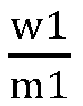
- Further, when

- Therefore, a numerical value of

- Optionally, the mass content w1 of the first polar substance in the first coating and the mass content m1 of the positive binder in the positive film layer have a ratio


- A mass content w2 of the second polar substance in the second coating and a mass content m2 of the negative binder in a negative film layer may have a ratio

- In the present application,

- Further, when

- Further, when

- Therefore, a numerical value of

- Optionally, the mass content w2 of the second polar substance in the second coating and the mass content m2 of the negative binder in the negative film layer may have a ratio


- In some embodiments, the mass content w1 of the first polar substance in the first coating and the mass content w2 of the second polar substance in the second coating may have a ratio

- In the present application,

- In the present application, by limiting


- Optionally, the mass content w1 of the first polar substance in the first coating and the mass content w2 of the second polar substance in the second coating have a ratio

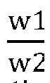
- Usually, coating quantities of the first polar substance and the second polar substance cannot be different greatly and are optionally basically equal, i.e.,

- In some embodiments, the first polar substance may have a mass content w1 of 80%-90% in the first coating.
- In the present application, w1 may reflect the content of the first polar substance in the first coating.
- In the present application, the first polar substance accounts for a main part in the first coating, which may increase the hydrogen bonds between the first polar substance and the positive binder, such that the first coating and the positive electrode have a better binding force. If the first polar substance has a content lower than 80% in the first coating and few hydrogen bonds are generated between the first polar substance and the positive binder, a binding performance between the separator and the positive electrode is improved limitedly, and an expansion improvement effect of the bare cell in the processing process and the cycle use process is not obvious; if the first polar substance has a content higher than 90% in the first coating, the base film is prone to blockage, thus reducing the air permeability and influencing the dynamic performance of the separator.
- Optionally, the first polar substance has a mass content w1 of 80%, 85%, 90%, or the like, in the first coating. W1 may be any above-mentioned point value or any range of values between the point values.
- In some embodiments, the positive binder may have a mass content m1 of 0.9%-1.2% in the positive film layer.
- In the present application, m1 may reflect the content of the positive binder in the positive film layer.
- When m1 is within this range, the positive electrode and the first coating may be bound firmly, thereby reducing the expansion of the bare cell in the processing process or the cycle use process, and improving the high-rate discharge performance and the cycle performance of the battery. Usually, the positive binder cannot have an excessively large content in a positive plate, and when m1 is greater than 1.2%, the electron transport channel may be blocked by the positive binder with an excessively high content, and in addition, the positive binder is usually an inert insulator and has poor conductivity and large polarization, thus influencing the cycle performance and the high-rate discharge performance of the battery. Usually, the positive binder also cannot have an excessively small content in the positive plate, and when m1 is less than 0.9%, the positive binder with an excessively low content may cause insufficient viscosity, and therefore, the positive electrode and the first coating have a small binding force.
- Optionally, the positive binder may have a mass content m1 of 0.9%, 1%, 1.2%, or the like, in the positive film layer. M1 may be any above-mentioned point value or any range of values between the point values.
- Thus, by limiting the above parameters w1, m1 within the reasonable ranges, the dynamic performance and the binding force between the first coating and the positive electrode may be considered, and an optimal ratio therebetween may be obtained, thus improving the high-rate discharge performance and the cycle performance of the battery.
- In some embodiments, the second polar substance may have a mass content w2 of 80%-90% in the second coating.
- In the present application, w2 may reflect the content of the second polar substance in the second coating.
- In the present application, the second polar substance accounts for a main part in the second coating, which may increase the hydrogen bonds between the second polar substance and the negative binder, such that the second coating and the negative electrode have a better binding force. If the second polar substance has a content lower than 80% in the second coating and few hydrogen bonds are generated between the second polar substance and the negative binder, a binding performance between the separator and the negative electrode is improved limitedly, and an expansion improvement effect of the bare cell in the processing process and the cycle use process is not obvious; if the second polar substance has a content higher than 90% in the second coating, the base film is prone to blockage, thus reducing the air permeability and influencing the dynamic performance of the separator.
- Optionally, the second polar substance has a mass content w2 of 80%, 85%, 90%, or the like, in the second coating. w2 may be any above-mentioned point value or any range of values between the point values.
- In some embodiments, the negative binder may have a mass content m2 of 2%-3% in the negative film layer.
- In the present application, m2 may reflect the content of the negative binder in the negative film layer.
- In the present application when m2 is within this range, the negative electrode and the second coating may be bound firmly, thereby reducing the expansion of the bare cell in the processing process or the cycle use process, and improving the high-rate discharge performance and the cycle performance of the battery. Usually, the negative binder cannot have an excessively large content in a negative plate, and when m1 is greater than 3%, the electron transport channel may be blocked by the negative binder with an excessively high content, and in addition, the negative binder is usually an inert insulator and has poor conductivity and large polarization, thus influencing the cycle performance and the high-rate discharge performance of the battery. Usually, the negative binder also cannot have an excessively small content in the negative plate, and when m1 is less than 2%, the negative binder with an excessively low content may cause insufficient viscosity, and therefore, the negative electrode and the second coating have a small binding force.
- Optionally, the negative binder may have a mass content m2 of 2%, 2.6%, 3%, or the like, in the negative film layer. m2 may be any above-mentioned point value or any range of values between the point values.
- Thus, by limiting the above parameters w2, m2 within the reasonable ranges, the dynamic performance and the binding force between the second coating and the negative electrode may be considered, and an optimal ratio therebetween may be obtained, thus improving the high-rate discharge performance and the cycle performance of the battery.
- In some embodiments, the first polar substance includes polyethylene oxide and polyacrylamide. The polyethylene oxide and the polyacrylamide may have a mass ratio C1 of (2-6):1.
- Usually, different polar substances may achieve different functions, and thus, advantages of the substances may be combined. Specifically, in the present application, in the first active substance, the polyethylene oxide is a lithium ion conductor, has characteristics of high conductivity, low activation energy, most negative electrode potential, or the like, may accelerate conduction of the lithium ions, and is required to account for a main part in the first polar substance. Since the polyacrylamide has a large chain length, a large molecular weight, and good thermal stability compared with the polyethylene oxide (PEO), and a surface connected with the positive electrode is usually oxidized at a high pressure, mixture of a small number of long chain molecules, such as the polyacrylamide, or the like, in the polyethylene oxide, particularly within the range defined in the present application, may improve cycle stability and the high-rate discharge performance of the battery.
- Further, if the polyethylene oxide and the polyacrylamide have a mass ratio C1 less than 2:1, since the polyacrylamide is not a lithium ion conductor, a lithium ion conduction rate is low, thus influencing the cycle performance and the high-rate discharge performance of the battery. If the polyethylene oxide and the polyacrylamide have a mass ratio C1 greater than 6:1, the polyacrylamide has an excessively low content, resulting in poor thermal stability.
- Optionally, the polyethylene oxide and the polyacrylamide may have a mass ratio C1 of 2:1, 3:1, 4.5:1, 5:1, 6:1, or the like. C1 may be any above-mentioned point value or any range of values between the point values.
- The second polar substance includes polyethylene imine and polyethylene oxide. The polyethylene imine and the polyethylene oxide may have a mass ratio C2 of (2-6):1.
- Usually, different polar substances may achieve different functions, and thus, advantages of the substances may be combined. Specifically, in the present application, in the second active substance, both the polyethylene imine and the polyethylene oxide are lithium ion conductors, have characteristics of high conductivity, low activation energy, most negative electrode potential, or the like, and may accelerate conduction of the lithium ions. Furthermore, the second active substance is located on a side connected with the negative electrode, and since the negative active substance, such as graphite, is prone to expansion, a binder with high polarity, such as polyethylene imine (PEI) is required to be selected; in addition, since polyethylene oxide is cheaper than polyethylene imine, a small amount of polyethylene oxide may be added into polyethylene imine in consideration of a cost factor, particularly within the range defined by the present application, such that the hydrogen bonds may be formed between the polyethylene oxide and the polyethylene imine while the cost is reduced, thus further increasing the binding force, reducing the expansion of the bare cell in the processing and cycle use processes, and improving the cycle performance and the high-rate discharge performance of the battery.
- If the polyethylene imine and the polyethylene oxide have a mass ratio C2 less than 2:1, since the polyethylene imine has high polarity, when the content is excessively low, few hydrogen bonds are formed between the second polar substance and the negative binder or the negative active substance, and the second coating and the negative electrode have a reduced binding force, thus increasing the expansion of the bare cell in the processing process and the cycle use process, and influencing the cycle performance and the high-rate discharge performance of the battery. If the polyethylene imine and the polyethylene oxide have a mass ratio C2 greater than 6:1, a cost is increased.
- Optionally, the polyethylene imine and the polyethylene oxide may have a mass ratio C2 of 2:1, 3:1, 4.5:1, 5:1, 6:1, or the like. C2 may be any above-mentioned point value or any range of values between the point values.
- In some embodiments, for example, polyamide may be one or a combination of more of polyacrylamide (PAM), nylon-66, nylon-6, or the like, in the first or second polar substance. The polyamide may have a weight-average molecular weight of 20,000-80,000, optionally 20,000, 30,000, 40,000, 50,000, 60,000, 70,000, 80,000, or the like, and the weight-average molecular weight of the polyamide may be any above-mentioned point value or any range of values between the point values.
- In some embodiments, for example, the polyolefin imine may be one or more of polyethylene imine (PEI), polyethylene polyamine, or the like, in the first or second polar substance. The polyolefin imine may have a weight-average molecular weight of 70,000-100,000, optionally 70,000, 80,000, 90,000, 100,000, or the like, and the weight-average molecular weight of the polyolefin imine may be any above-mentioned point value or any range of values between the point values.
- In some embodiments, for example, the polyolefin oxide may be polyethylene oxide (PEO), or the like, in the first or second polar substance. The polyolefin oxide may have a weight-average molecular weight of 100,000-200,000, optionally 100,000, 120,000, 140,000, 160,000, 180,000, 200,000, or the like, and the weight-average molecular weight of the polyolefin oxide may be any above-mentioned point value or any range of values between the point values.
- In some embodiments, in the first or second polar substance, for example, the polyurethane may be a polymer with a general formula containing - NHCOO-, and more specifically, the polyurethane may be formed by polymerizing at least one monomer of polyisocyanate, toluene diisocyanate (TDI), methylenediphenyl-4,4'-diisocyanate (MDI), polyaryl polym ethylene isocyanate (PAPI), or by copolymerizing two or more monomers, the polymerization including random copolymerization, block copolymerization, or the like. The polyurethane may have a weight-average molecular weight of 1,000-10,000, optionally 1,000, 5,000, 10,000, or the like, and the weight-average molecular weight of the polyurethane may be any above-mentioned point value or any range of values between the point values.
- In some embodiments, in the first or second polar substance, the polyurea may be, for example, a polymer with a general formula containing -NHCONH-, and more specifically, may be one or more of polyurea, urea-formaldehyde resin, or the like. The polyurea may have a weight-average molecular weight of 5,000-50,000, optionally 5,000, 10,000, 20,000, 30,000, 40,000, 50,000, or the like, and the weight-average molecular weight of the polyurea may be any above-mentioned point value or any range of values between the point values.
- In some embodiments, the first coating includes a first reinforcing agent, and the mass content w1 of the first polar substance in the first coating and a mass content k1 of the first reinforcing agent in the first coating may have a mass ratio

- In the present application,

- In the present application, since the first polar substance has a risk of separation from the base film in the middle or late period of the cycle of the battery, the binding force of the first polar substance on the base film may be enhanced by the first reinforcing agent. Only when the ratio of the first polar substance to the first reinforcing agent on the separator is within the reasonable range, the expansion of the bare cell in the processing process and the cycle expansion rate in the cycle use process may be reduced, and the cycle performance and the high-rate discharge performance of the battery may be improved. When


- Further, by analyzing a mechanism of forming the hydrogen bond between the first reinforcing agent and the first polar substance, since the hydrogen bond Y-H-F is easily formed between the first reinforcing agent (containing F) and the first polar substance (-YH), the first polar substance may stably exist on the separator by the first reinforcing agent, thereby reducing the expansion of the bare cell in the processing process and the cycle expansion rate in the cycle use process, and improving the cycle performance and the high-rate discharge performance of the battery.
- Optionally, the mass content w1 of the first polar substance in the first coating and the mass content k1 of the first reinforcing agent in the first coating may have a mass ratio


- In some embodiments, the second coating includes a second reinforcing agent, and the mass content w2 of the second polar substance in the second coating and a mass content k2 of the second reinforcing agent in the second coating may have a mass ratio

- In the present application,

- In the present application, since the second polar substance has a risk of separation from the base film in the middle or late period of the cycle of the battery, the binding force of the second polar substance on the base film may be enhanced by the second reinforcing agent. Only when the ratio of the second polar substance to the second reinforcing agent on the separator is within the reasonable range, the expansion of the bare cell in the processing process and the cycle expansion rate in the cycle use process may be reduced, and the cycle performance and the high-rate discharge performance of the battery may be improved. When


- Further, by analyzing a mechanism of forming the hydrogen bond between the second reinforcing agent and the second polar substance, the hydrogen bond Y-H-F is easily formed between the second reinforcing agent (containing F) and the second polar substance (-YH), and the second polar substance may stably exist on the separator by the second reinforcing agent, thereby reducing the expansion of the bare cell in the processing process and the cycle expansion rate in the cycle use process, and improving the cycle performance and the high-rate discharge performance of the battery.
- Optionally, the mass content w2 of the second polar substance in the second coating and the mass content k2 of the second reinforcing agent in the second coating may have a mass ratio


- In some embodiments, the mass content k1 of the first reinforcing agent in the first coating is not higher than the mass content k2 of the second reinforcing agent in the second coating.
- In the present application, k1 and k2 may reflect contents of the reinforcing agents with which the two surfaces of the separator are coated, and k1 and k2 cannot be significantly different.
- Usually, when k1 is not higher than k2, the tension of the separator may be kept consistent, and the separator is more stable, which may, on the one hand, prevent the short circuit risk caused by inconsistent tension, and on the other hand, improve the cycle performance and the high-rate discharge performance of the battery. If k1 is significantly different from k2, the two surfaces of the separator have inconsistent tension, the separator is wrinkled, bubbles are generated on the surface, immersion by the electrolyte is not good, lithium is prone to precipitation, the cycle performance is deteriorated, cycle attenuation is accelerated, and the high-rate discharge performance is deteriorated.
- In some embodiments, the mass content k1 of the first reinforcing agent in the first coating and the mass content k2 of the second reinforcing agent in the second coating may have a ratio

- In the present application,


- Preferably, the two surfaces of the separator have basically consistent contents, which may reduce a difference of the two surfaces of the separator.
- Optionally, the mass content k1 of the first reinforcing agent in the first coating and the mass content k2 of the second reinforcing agent in the second coating may have a ratio


- In some embodiments, the first reinforcing agent may have a mass content k1 of 10%-20% in the first coating. The second reinforcing agent may have a mass percentage content k2 of 10%-20% in the second coating.
- In the present application, k1 may reflect the content of the reinforcing agent in the first coating. k2 may reflect the content of the second reinforcing agent in the second coating.
- In the present application, the content of the first reinforcing agent in the first coating cannot be significantly different from the content of the second reinforcing agent in the second coating; if k1 is significantly different from k2, the two surfaces of the separator have inconsistent tension, the separator is wrinkled, bubbles are generated on the surface, immersion by the electrolyte is not good, lithium is prone to precipitation, the cycle performance is deteriorated, cycle attenuation is accelerated, and the high-rate discharge performance is deteriorated. Thus, by limiting the above parameters within the reasonable ranges, there may exist small influences on lithium ion transport dynamics while the stability of the separator is improved, dynamics and viscosity may be considered to obtain an optimal ratio, and the cycle performance and the high-rate discharge performance of the battery may be improved.
- Optionally, the two surfaces of the separator have basically consistent contents, which may reduce the difference of the two surfaces of the separator; the separator has consistent tension and is prevented from being wrinkled.
- Optionally, the first reinforcing agent may have a mass content k1 of 14%, 16.6%, 18%, 19%, 20%, or the like, in the first coating. K1 may be any above-mentioned point value or any range of values between the point values.
- Optionally, the second reinforcing agent may have a mass percentage content k2 of 10%, 11%, 14%, 15.8%, 16.6%, 17%, 20%, or the like, in the second coating. k2 may be any above-mentioned point value or any range of values between the point values.
- In some embodiments, the first reinforcing agent or the second reinforcing agent includes one or more of polyvinylidene difluoride and sodium alginate; due to a low cost, the polyvinylidene difluoride is preferred. The positive binder includes polyvinylidene fluoride. The negative binder includes more than one of styrene butadiene rubber and sodium alginate.
- In some embodiments, the first or second reinforcing agent has a weight-average molecular weight of 500-600,000, optionally 500, 10,000, 100,000, 200,000, 300,000, 400,000, 500,000, 600,000, or the like, and the weight-average molecular weight of the first or second reinforcing agent may be any above-mentioned point value or any range of values between the point values.
- Further, the polyvinylidene difluoride may have a weight-average molecular weight of 100,000-600,000, optionally 100,000, 200,000, 300,000, 400,000, 500,000, 600,000, or the like, and the weight-average molecular weight of the polyvinylidene difluoride may be any above-mentioned point value or any range of values between the point values.
- Further, the sodium alginate may have a weight-average molecular weight of 500-50,000, optionally 500, 10,000, 20,000, 30,000, 40,000, 50,000, or the like, and the weight-average molecular weight of the sodium alginate may be any above-mentioned point value or any range of values between the point values. The polyvinylidene difluoride and the sodium alginate may be applied to the first reinforcing agent, the second reinforcing agent, the positive binder or the negative binder.
- In some embodiments, the first coating and the second coating may have a mass ratio of 1:(1-1.5).
- In the present application, the first coating and the second coating may reflect the contents of the coated substances on the two surfaces of the separator, and the two contents cannot be significantly different; thus, by limiting the coating quantities of the first coating and the second coating within the reasonable ranges, the separator may have consistent tension and is more stable, which may, on the one hand, prevent the short circuit risk caused by inconsistent tension, and on the other hand, improve the cycle performance and the high-rate discharge performance of the battery. If the contents of the first and second coatings are significantly different, the two surfaces of the separator have inconsistent tension, the separator is wrinkled, bubbles are generated on the surface, immersion by the electrolyte is not good, lithium is prone to precipitation, the cycle performance is deteriorated, cycle attenuation is accelerated, and the high-rate discharge performance is deteriorated.
- Optionally, the first coating and the second coating may have a mass ratio of 1:1, 1:2, 1:3, 1:4, 1:5, or the like. The mass ratio of the first coating to the second coating may be any above-mentioned point value or any range of values between the point values.
- In some embodiments, the first coating or the second coating may further include a filler which may be, for example, alumina, and the filler may improve heat resistance and stability of the coating, and when used in combination with the first polar substance, may reduce the expansion of the bare cell in the processing process and the cycle use process, and improve the cycle performance and the high-rate discharge performance of the battery. A content of the filler is not particularly limited; for example, the filler may have a mass proportion greater than 0% and less than or equal to 25% in the first or second coating. The filler in the first or second coating with a content greater than 25% may block pores of the base film, thus resulting in a slow ion transport rate and affecting the cycle performance and the high-rate discharge performance of the battery.
- Optionally, the filler may have a mass percent of 3.2%, 8%, 10%, 15%, 18.9%, 20%, 25%, or the like, in the first or second coating. The mass percent of the filler in the first or second coating may be any above-mentioned point value or any range of values between the point values.
- In some embodiments, the first coating is prepared from first coating slurry. The first coating slurry includes the first polar substance, the first reinforcing agent and a first solvent; the first coating slurry may have viscosity of 8,000mpa.s-12,000mpa.s.
- In the present application, the first coating slurry may be prepared using a method known in the art. For example, the first polar substance and the first reinforcing agent may be mixed in the first solvent to form uniform slurry, i.e., the first coating slurry, and optionally, in the preparation process of the first coating slurry, the first polar substance, the first reinforcing agent and the filler may be mixed and then dissolved in the first solvent to prepare the first coating slurry. For quantities of the substances, reference may be made to the foregoing setting of the mass ratios of the components in the first coating in the present application.
- In the present application, viscosity of the first coating slurry greatly influences coating and an electrochemical performance of the cell, and if the first coating slurry has excessively high viscosity, gel is prone to formation, and coating is uneven, resulting in poor consistency of the cell and reduction of the cycle performance and the high-rate discharge performance of the battery. If the first coating slurry has excessively low viscosity, the base film cannot be well coated with the first coating slurry. Thus, by limiting the viscosity of the first coating slurry within the proper range, the base film may be well coated with the first coating slurry, the consistency of the cell may be guaranteed to be good, and the cycle performance and the high-rate discharge performance of the battery may be improved.
- Optionally, the first coating slurry may have viscosity of 8,000mpa.s, 9,000mpa.s, 10,000mpa.s, 11,000mpa.s, 12,000mpa.s, or the like. A weight-average molecular weight of the first coating slurry may be any above-mentioned point value or any range of values between the point values.
- Further, the first solvent is usually not limited, and more specifically, when the first reinforcing agent is sodium alginate, selection of the first solvent is not limited. When the first reinforcing agent is polyvinylidene difluoride, the first solvent is an organic solvent which may be, for example, N,N-dimethyl pyrrolidone, acetone, or the like.
- In some embodiments, the second coating is prepared from second coating slurry, and the second coating may be prepared using a method known in the art. The second coating slurry includes the second polar substance, the second reinforcing agent and a second solvent; the second coating slurry has viscosity of 5,000mpa.s-20,000mpa.s.
- In the present application, the second coating slurry may be prepared using a method known in the art. For example, the second polar substance and the second reinforcing agent may be mixed in the second solvent to form uniform slurry, i.e., the second coating slurry, and optionally, in the preparation process of the second coating slurry, the second polar substance, the second reinforcing agent and the filler may be mixed and then dissolved in the second solvent to prepare the second coating slurry. For quantities of the substances, reference may be made to the foregoing setting of the mass ratios of the components in the second coating in the present application.
- In the present application, viscosity of the second coating slurry greatly influences coating and an electrochemical performance of the cell, and if the second coating slurry has excessively high viscosity, gel is prone to formation, and coating is uneven, resulting in poor consistency of the cell and reduction of the cycle performance and the high-rate discharge performance of the battery. If the second coating slurry has excessively low viscosity, the base film cannot be well coated with the second coating slurry. Thus, by limiting the viscosity of the second coating slurry within the proper range, the base film may be well coated with the second coating slurry, the consistency of the cell may be guaranteed to be good, and the cycle performance and the high-rate discharge performance of the battery may be improved.
- Optionally, the second coating slurry may have viscosity of 5,000mpa.s, 8,000mpa.s, 10,000mpa.s, 13,000mpa.s, 15,000mpa.s, 18,000mpa.s, 20,000mpa.s, or the like. A weight-average molecular weight of the second coating slurry may be any above-mentioned point value or any range of values between the point values.
- Further, the second solvent is usually not limited, and more specifically, when the second reinforcing agent is sodium alginate, selection of the second solvent is not limited. When the second reinforcing agent is polyvinylidene difluoride, the second solvent is an organic solvent which may be, for example, N,N-dimethyl pyrrolidone, acetone, or the like.
- In some embodiments, a type of the base film is not particularly limited in the present application, and any well-known base film with a porous structure having good chemical stability and mechanical stability may be selected.
- In some embodiments, the base film may be made of at least one of glass fibers, non-woven fabrics, polyethylene, polypropylene and polyvinylidene difluoride. The base film may be a single-layer film or a multi-layer composite film, which is not particularly limited. When the base film is a multi-layer composite film, respective layers may be made of same or different materials, which is not particularly limited.
- The negative electrode includes a negative current collector and a negative film layer provided on at least one surface of the negative current collector, the negative film layer including a negative active component.
- In some embodiments, the negative active component includes a silicon-carbon mixture, and silicon in the silicon-carbon mixture may have a particle size of 0.1-0.5 microns. Carbon is mixed carbon of artificial graphite and natural graphite.
- In the present application, the particle size of the silicon greatly influences an electrochemical performance, micron silicon has a smaller specific surface area and fewer side reactions than nanometer silicon, the battery has the better cycle performance and high-rate discharge performance, and therefore, micron silicon is selected.
- Optionally, the silicon has a particle size of 0.1 microns, 0.3 microns, 0.5 microns, or the like. The particle size of the silicon may be any above-mentioned point value or any range of values between the point values.
- Optionally, the silicon-carbon mixture may have C:Si of 95-97: 3-5, or the like. More specifically, C:Si may be 95:5.
- Further, the silicon-carbon mixture may have a content of 95%-97% in the negative film layer. Since the content of the silicon-carbon mixture affects an energy density of the cell, a high capacity of the battery may be realized only when the silicon-carbon mixture has a content greater than 95% in the negative film layer, so as to improve the cycle performance and the high-rate discharge performance of the battery.
- Optionally, the silicon-carbon mixture may have a content of 95.9%, 96%, 96.7%, 96.8%, 97%, or the like, in the negative film layer. The content of the silicon-carbon mixture in the negative film layer may be any above-mentioned point value or any range of values between the point values.
- Optionally, the negative active component may be a negative active material for a battery well known in the art. As an example, the negative active component may include at least one of the following materials: artificial graphite, natural graphite, soft carbon, hard carbon, silicon-based materials, tin-based materials, lithium titanate, or the like. The silicon-based material may be at least one of elemental silicon, a silicon-oxygen compound, a silicon-nitrogen composite, and a silicon alloy. The tin-based material may be at least one of elemental tin, a tin-oxide compound, and a tin alloy. However, the present application is not limited to these materials, and other conventional materials which may be used as the negative active component of the battery may be used. Only one of these negative active components may be used, or more than two thereof are used in combination.
- As an example, the negative current collector has two surfaces opposite in a thickness direction thereof, and the negative film layer is provided on one or both of the two opposite surfaces of the negative current collector.
- In some embodiments, metal foil or a composite current collector may be used as the negative current collector. For example, copper foil may be used as the metal foil. The composite current collector may include a high molecular material base layer and a metal layer formed on at least one surface of the high molecular material base layer. The composite current collector may be formed by forming a metal material (copper, a copper alloy, nickel, a nickel alloy, titanium, a titanium alloy, silver, a silver alloy, or the like) on the base layer of high molecular material (such as polypropylene (PP), polyethylene terephthalate (PET), polybutylene terephthalate (PBT), polystyrene (PS), polyethylene (PE), or the like).
- In some embodiments, the negative film layer further optionally includes a negative binder. The negative binder may be at least one of styrene butadiene rubber (SBR), polyacrylic acid (PAA), sodium polyacrylate (PAAS), polyacrylamide (PAM), polyvinyl alcohol (PVA), sodium alginate (SA), polymethacrylic acid (PMAA), and carboxymethyl chitosan (CMCS). Optionally, the negative binder is styrene butadiene rubber (SBR) and sodium alginate (SA).
- In some embodiments, the negative film layer further optionally includes a conductive agent. The conductive agent may be at least one of superconducting carbon, acetylene black, carbon black, Ketjen black, carbon dots, carbon nanotubes, graphene, and carbon nanofibers.
- In some embodiments, the negative film layer may further optionally include other additives, such as a thickener (for example, sodium carboxymethyl cellulose (CMC-Na)), or the like.
- In some embodiments, the negative electrode may be fabricated by: dispersing the above components for fabricating the negative electrode, such as the negative active component, the conductive agent, the binder, and any other component, in a solvent (for example, deionized water) to form negative slurry; and coating the negative current collector with the negative slurry, and performing drying, cold pressing and other processes to obtain the negative electrode.
- The positive electrode includes a positive current collector and a positive film layer provided on at least one surface of the positive current collector, the positive film layer including a positive material according to the first aspect of the present application.
- In some embodiments, the positive electrode includes a positive material LiNixCoyMnzO2, where x+y+z=1, and x=0.5-0.9, optionally x=0.5-0.7 or x=0.8-0.9.
- In the present application, generally speaking, the positive material may have a nickel content greater than 0.5, but different positive system bare cells have different expansion changes, and the separator in the present application especially has a remarkable improvement effect on the cycle expansion rate of the bare cell containing a high-nickel positive material.
- More specifically, when the nickel content x=0.5-0.7, unit cell parameters of the positive material change greatly, the positive material also has a large volume change, and final expansion of the bare cell changes greatly compared with initial expansion thereof, but the obtained bare cell has a small cycle expansion rate, and in the present application, within the aforementioned range, the cycle expansion rate of the bare cell is improved more remarkably, and a cycle conservation rate is better. When the nickel content is, for example, 0.8-0.9, although the unit cell parameters of the positive material have small changes, since the bare cell also has a small final cycle expansion rate, this nickel content is also within the scope claimed by the present application.
- Optionally, x=0.4, x=0.5, x=0.6, x=0.7, x=0.8, x=0.9, or the like, and the nickel content may be any above-mentioned point value or any range of values between the point values.
- Optionally, the positive material may be LiNi0.4Co0.4Mn0.2O2, LiNi0.5Co0.2Mn0.3O2, LiNi0.6Co0.2Mn0.2O2, LiNi0.7Co0.2Mn0.1O2, LiNi0.8Co0.1Mn0.1O2, LiNi0.9Co0.05Mn0.05O2, or the like.
- Further optionally, the positive active material may be a positive active material for a battery well known in the art. As an example, the positive active material may include at least one of the following materials: lithium-contained phosphate of an olivine structure, lithium transition metal oxide and respective modified compounds thereof. However, the present application is not limited to these materials, and other conventional materials which may be used as the positive active material of the battery may be used. Only one of these positive active materials may be used, or more than two thereof are used in combination. Examples of the lithium transition metal oxide may include, but are not limited to, at least one of lithium cobalt oxide (for example, LiCoO2), lithium nickel oxide (for example, LiNiO2), lithium manganese oxide (for example, LiMnO2, LiMn2O4), lithium nickel cobalt oxide, lithium manganese cobalt oxide, lithium nickel manganese oxide, lithium nickel cobalt manganese oxide (for example, LiNi1/3Co1/3Mn1/3O2 (also abbreviated as NCM333), LiNi0.5Co0.25Mn0.25O2 (also abbreviated as NCM211), lithium nickel cobalt aluminum oxide (for example, LiNi0.85Co0.15Al0.05O2), and modified compounds thereof, or the like. Examples of the lithium-contained phosphate of an olivine structure may include, but are not limited to, at least one of lithium iron phosphate (for example, LiFePO4 (also abbreviated as LFP)), a composite material of lithium iron phosphate and carbon, lithium manganese phosphate (for example, LiMnPO4), a composite material of lithium manganese phosphate and carbon, lithium iron manganese phosphate, and a composite material of lithium iron manganese phosphate and carbon.
- As an example, the positive current collector has two surfaces opposite in a thickness direction thereof, and the positive film layer is provided on one or both of the two opposite surfaces of the positive current collector.
- In some embodiments, metal foil or a composite current collector may be used as the positive current collector. For example, aluminum foil may be used as the metal foil. The composite current collector may include a high molecular material base layer and a metal layer formed on at least one surface of the high molecular material base layer. The composite current collector may be formed by forming a metal material (aluminum, an aluminum alloy, nickel, a nickel alloy, titanium, a titanium alloy, silver, a silver alloy, or the like) on the base layer of high molecular material (such as polypropylene (PP), polyethylene terephthalate (PET), polybutylene terephthalate (PBT), polystyrene (PS), polyethylene (PE), or the like).
- In some embodiments, the positive film layer further optionally includes a positive binder. As an example, the positive binder may include at least one of polyvinylidene fluoride (PVDF), polytetrafluoroethylene (PTFE), a vinylidene fluoride-tetrafluoroethylene-propylene terpolymer, a vinylidene fluoride-hexafluoropropylene-tetrafluoroethyleneterpolymer, a tetrafluoroethylene-hexafluoropropylene copolymer, and fluorine-contained acrylate resin. Optionally, the positive binder is polyvinylidene fluoride (PVDF).
- In some embodiments, the positive film layer further optionally includes a conductive agent. As an example, the conductive agent may include at least one of superconducting carbon, acetylene black, carbon black, Ketjen black, carbon dots, carbon nanotubes, graphene, and carbon nanofibers.
- In some embodiments, the positive electrode may be fabricated by: dispersing the above components for fabricating the positive electrode, such as the positive material, the conductive agent, the binder, and any other component, in a solvent (for example, N-methyl pyrrolidone) to form positive slurry; and coating the positive current collector with the positive slurry, and performing drying, cold pressing and other processes to obtain the positive electrode.
- The electrolyte plays a role of conducting ions between the positive plate and the negative plate. A type of the electrolyte is not particularly limited in the present application and may be selected as desired. For example, the electrolyte may be in a liquid, gel, or all solid state.
- In some embodiments, the electrolyte is an electrolyte solution. The electrolyte includes electrolyte salt and a solvent.
- In some embodiments, the electrolyte salt may be at least one of lithium hexafluorophosphate, lithium tetrafluoroborate, lithium perchlorate, lithium hexafluoroarsenate, lithium bis-fluorosulfonylimide, lithium bis-trifluoromethanesulfonylimide, lithium trifluoromethanesulfonate, lithium difluorophosphate, lithium difluorooxalato borate, lithium dioxalato borate, lithium difluorobisoxalate phosphate, and lithium tetrafluorooxalato phosphate.
- In some embodiments, the solvent may be at least one of ethylene carbonate, propylene carbonate, ethyl methyl carbonate, diethyl carbonate, dimethyl carbonate, dipropyl carbonate, methyl propyl carbonate, ethyl propyl carbonate, butylene carbonate, fluoroethylene carbonate, methyl formate, methyl acetate, ethyl acetate, propyl acetate, methyl propionate, ethyl propionate, propyl propionate, methyl butyrate, ethyl butyrate, 1,4-butyrolactone, sulfolane, dimethyl sulfone, methyl ethyl sulfone, and diethyl sulfone.
- In some embodiments, the electrolyte further optionally includes an additive. For example, the additive may include a negative film layer forming additive and a positive film layer forming additive, and may further include an additive capable of improving certain performances of the battery, such as an additive for improving an overcharge performance of the battery, an additive for improving a high-temperature or low-temperature performance of the battery, or the like.
- The battery according to the present application is described below with reference to the drawings as appropriate.
- One embodiment of the present application provides a secondary battery. Usually, the secondary battery includes a positive electrode, a negative electrode, an electrolyte, and a separator. During a charging and discharging process of the battery, active ions are inserted and extracted back and forth between the positive electrode and the negative electrode. The electrolyte plays a role of conducting the ions between the positive electrode and the negative electrode. The separator is provided between a positive plate and a negative plate, mainly functions to prevent a short circuit of the positive electrode and the negative electrode, and meanwhile may allow the ions to pass.
- In some embodiments, the positive electrode, the negative electrode and the separator may be manufactured into an electrode assembly with a winding process or a lamination process.
- In some embodiments, the secondary battery may include an outer package. The outer package may be configured to encapsulate the electrode assembly and the electrolyte.
- In some embodiments, the outer package of the secondary battery may be a hard shell, such as a hard plastic shell, an aluminum shell, a steel shell, or the like. The outer package of the secondary battery may also be a soft package, such as a bag-type soft package. The soft package may be made of plastic, such as polypropylene, polybutylene terephthalate, polybutylene succinate, or the like.
- A shape of the secondary battery is not particularly limited in the present application, and may be a cylindrical shape, a square shape, or any other shape. For example,
FIG. 3 shows asecondary battery 5 of a square structure as an example. - In some embodiments, referring to
FIG. 4 , the outer package may include ahousing 51 and acover plate 53. Thehousing 51 may include a bottom plate and a side plate connected to the bottom plate, and the bottom plate and the side plate enclose an accommodating cavity. Thehousing 51 has an opening communicated with the accommodating cavity, and thecover plate 53 may cover the opening to close the accommodating cavity. The positive plate, the negative plate and the separator may form theelectrode assembly 52 with a winding process or a lamination process. Theelectrode assembly 52 is encapsulated within the accommodating cavity. The electrolyte immerses theelectrode assembly 52. One ormore electrode assemblies 52 may be contained in thesecondary battery 5, and those skilled in the art may make a choice according to specific practical requirements. - In addition, the battery module, the battery pack and the electric device according to the present invention will be described below with reference to the drawings as appropriate.
- In some embodiments, the secondary batteries may be assembled into a battery module, one or more secondary batteries may be contained in the battery module, and the specific number may be selected by those skilled in the art according to an application and a capacity of the battery module.
-
FIG. 5 shows abattery module 4 as an example. Referring toFIG. 5 , a plurality ofsecondary batteries 5 may be sequentially arranged in thebattery module 4 in a length direction of thebattery module 4. Certainly, thesecondary batteries 5 may be arranged in any other way. The plurality ofsecondary batteries 5 may be further fixed by fasteners. - Optionally, the
battery module 4 may further include a casing having an accommodating space in which the plurality ofsecondary batteries 5 are accommodated. - In some embodiments, the above-mentioned battery modules may be further assembled into a battery pack, one or more battery modules may be contained in the battery pack, and the specific number may be selected by those skilled in the art according to an application and a capacity of the battery pack.
-
FIGS. 6 and 7 show abattery pack 1 as an example. Referring toFIGS. 6 and 7 , thebattery pack 1 may include a battery box and a plurality ofbattery modules 4 arranged in the battery box. The battery box includes anupper box 2 and alower box 3, and theupper box 2 may cover thelower box 3 to form an enclosed space for accommodating thebattery module 4. The plurality ofbattery modules 4 may be arranged in the battery box in any manner. - In addition, the present application further provides an electric device, including at least one of the secondary battery, the battery module and the battery pack according to the present application. The secondary battery, the battery module, or the battery pack may be used as a power source or an energy storage unit of the electric device. The electric device may include, but is not limited to, a mobile apparatus (for example, a mobile phone, a notebook computer, or the like), an electric vehicle (for example, a battery electric vehicle, a hybrid electric vehicle, a plug-in hybrid electric vehicle, an electric bicycle, an electric scooter, an electric golf cart, an electric truck, or the like), an electric train, a ship, a satellite, an energy storage system, or the like.
- The secondary battery, the battery module, or the battery pack may be selected according to use requirements of the electric device.
-
FIG. 8 shows an electric device as an example. The electric device is a battery electric vehicle, a hybrid electric vehicle, a plug-in hybrid electric vehicle, or the like. In order to meet demands of the electric device for high power and high energy density of the secondary battery, a battery pack or a battery module may be used. - As another example, the device may be a mobile phone, a tablet computer, a notebook computer, or the like. Usually, the device is required to be thin and light, and a secondary battery may be used as the power source thereof.
- Hereinafter, examples of the present application will be described. The examples described below are illustrative, and merely used to explain the present application. The examples shall not be construed to limit the present application. If the specific technologies or conditions are not specified in the examples, a step will be performed in accordance with the techniques or conditions described in the literature in the art or in accordance with the product instructions. The reagents or instruments used in the present invention, the manufacturers of which are not indicated, are the commercially available conventional products.
-
- 1) A first polar substance PEO and alumina were dissolved in NMP according to a mass ratio of 80:20, the mixture was stirred to be even to obtain first coating slurry, and a surface A of a PE base film (surface of the PE base film close to a positive electrode) was coated with the first coating slurry using a gravure coating method.
- 2) A second polar substance PEI and alumina were dissolved in deionized water according to a mass ratio of 80:20, the mixture was stirred to be even to obtain second coating slurry, and a surface B of the PE base film (surface of the PE base film close to a negative electrode) was coated with the second coating slurry using a gravure coating method.
- 3) The PE base film coated with the first coating slurry in step 1) and the second coating slurry in step 2) was dried at 60°C for 1h to form a first coating and a second coating on the two surfaces of the PE base film, and the separator was obtained.
- A positive active substance LiNi0.6Co0.2Mn0.2O2, a positive binder PVDF and conductive carbon were mixed according to a mass ratio of 97:1.07:1.93 and dissolved in NMP, the mixture was stirred for 6h to obtain positive slurry, aluminum foil was coated with the positive slurry, and drying and cold pressing were performed to obtain the positive electrode.
- A mass content w1 of the first polar substance in the first coating and a mass content m1 of the positive binder in a positive film layer had a ratio

- SA and SBR were mixed according to a mass ratio of 80:20 to obtain a negative binder, a negative active substance (carbon-silicon mixture (C:Si=95:5)), the negative binder and carbon nanotubes were mixed according to a mass ratio of 97:2.66:0.34 and dissolved in water, the mixture was stirred for 6h to obtain negative slurry, copper foil was coated with the negative slurry, and drying and cold pressing were performed to obtain the negative electrode.
- A mass content w2 of the second polar substance in the second coating and a mass content m2 of the negative binder in a negative film layer had a ratio

- The positive electrode, the separator and the negative electrode were stacked in sequence, the first coating of the separator being in contact with the positive electrode, and the second coating of the separator being in contact with the negative electrode; and then, the positive electrode, the separator and the negative electrode were wound to obtain a bare cell. The bare cell was placed into an aluminum shell, a top cover was welded, and liquid injection, standing at a high temperature, formation, aging and other processes were performed to obtain the lithium ion battery.
- For the fabrication process of the lithium ion battery, reference was overall made to example 1-1 except that the positive active substance LiNi0.6Co0.2Mn0.2O2, the positive binder PVDF and the conductive carbon had a mass ratio of 97:1:2, and the negative active substance (carbon-silicon mixture), the negative binder and the carbon nanotubes had a mass ratio of 97:2.5:0.5.
- The mass content w1 of the first polar substance in the first coating and the mass content m1 of the positive binder in the positive film layer had a ratio


- For the fabrication process of the lithium ion battery, reference was overall made to example 1-1 except that the positive active substance LiNi0.6Co0.2Mn0.2O2, the positive binder PVDF and the conductive carbon had a mass ratio of 97:0.91:2.09, and the negative active substance (carbon-silicon mixture), the negative binder and the carbon nanotubes had a mass ratio of 97:2.2:0.8.
- The mass content w1 of the first polar substance in the first coating and the mass content m1 of the positive binder in the positive film layer had a ratio


- For the fabrication process of the lithium ion battery, reference was overall made to example 1-1 except that the positive active substance LiNi0.6Co0.2Mn0.2O2, the positive binder PVDF and the conductive carbon had a mass ratio of 97:0.86:2.14, and the negative active substance (carbon-silicon mixture), the negative binder and the carbon nanotubes had a mass ratio of 97:2:1.
- The mass content w1 of the first polar substance in the first coating and the mass content m1 of the positive binder in the positive film layer had a ratio


- For the fabrication process of the lithium ion battery, reference was overall made to example 1-1 except that the positive active substance LiNi0.6Co0.2Mn0.2O2, the positive binder PVDF and the conductive carbon had a mass ratio of 97:0.82:2.18, and the negative active substance (carbon-silicon mixture), the negative binder and the carbon nanotubes had a mass ratio of 97:1.77:1.23.
- The mass content w1 of the first polar substance in the first coating and the mass content m1 of the positive binder in the positive film layer had a ratio


- For the fabrication process of the lithium ion battery, reference was overall made to example 1-1 except that the positive active substance LiNi0.6Co0.2Mn0.2O2, the positive binder PVDF and the conductive carbon had a mass ratio of 97:0.8:2.2, and the negative active substance (carbon-silicon mixture), the negative binder and the carbon nanotubes had a mass ratio of 97:1.6:1.4.
- The mass content w1 of the first polar substance in the first coating and the mass content m1 of the positive binder in the positive film layer had a ratio


- For the fabrication process of the lithium ion battery, reference was overall made to example 1-1 except that the positive active substance LiNi0.6Co0.2Mn0.2O2, the positive binder PVDF and the conductive carbon were mixed according to a mass ratio of 97:0.76:2.24, and the negative active substance (carbon-silicon mixture), the negative binder and the carbon nanotubes were mixed according to a mass ratio of 97:1.5:1.5.
- The mass content w1 of the first polar substance in the first coating and the mass content m1 of the positive binder in the positive film layer had a ratio


-
- 1) A first polar substance PAM and alumina were dissolved in NMP according to a mass ratio of 96.8:3.2, the mixture was stirred to be even to obtain first coating slurry, and a surface A of a PE base film (surface of the PE base film close to a positive electrode) was coated with the first coating slurry using a gravure coating method.
- 2) A second polar substance PEO and alumina were dissolved in deionized water according to a mass ratio of 77.5:22.5, the mixture was stirred to be even to obtain second coating slurry, and a surface B of the PE base film (surface of the PE base film close to a negative electrode) was coated with the second coating slurry using a gravure coating method.
- 3) The PE base film coated with the first coating slurry in step 1) and the second coating slurry in step 2) was dried at 60°C for 1h to form a first coating and a second coating on the two surfaces of the PE base film, and the separator was obtained.
- A mass content w1 of the first polar substance in the first coating and a mass content w2 of the second polar substance in the second coating had a ratio

- A positive active substance LiNi0.6Co0.2Mn0.2O2, a positive binder PVDF and conductive carbon were mixed according to a mass ratio of 97:1:2 and dissolved in NMP, the mixture was stirred for 6h to obtain positive slurry, aluminum foil was coated with the positive slurry, and drying and cold pressing were performed to obtain the positive electrode.
- SA and SBR were mixed according to a mass ratio of 80:20 to obtain a negative binder, a negative active substance (carbon-silicon mixture (C:Si=95:5)), the negative binder and carbon nanotubes were mixed according to a mass ratio of 97:2.5:0.5 and dissolved in water, the mixture was stirred for 6h to obtain negative slurry, copper foil was coated with the negative slurry, and drying and cold pressing were performed to obtain the negative electrode.
- The positive electrode, the separator and the negative electrode were stacked in sequence, the first coating of the separator being in contact with the positive electrode, and the second coating of the separator being in contact with the negative electrode; and then, the positive electrode, the separator and the negative electrode were wound to obtain a bare cell. The bare cell was placed into an aluminum shell, a top cover was welded, and liquid injection, standing at a high temperature, formation, aging and other processes were performed to obtain the lithium ion battery.
- This example was basically same as example 2-1 except that the first polar substance PAM and the alumina had a mass ratio of 85:15, and the second polar substance PEO and the alumina had a mass ratio of 85:15. The mass content w1 of the first polar substance in the first coating and the mass content w2 of the second polar substance in the second coating had a ratio

- For the fabrication process of the lithium ion battery, reference was overall made to example 2-1 except that the first polar substance PAM and the alumina had a mass ratio of 71.1:28.9, and the second polar substance PEO and the alumina had a mass ratio of 92.5:7.5. The mass content w1 of the first polar substance in the first coating and the mass content w2 of the second polar substance in the second coating had a ratio
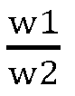
- For the fabrication process of the lithium ion battery, reference was overall made to example 2-1 except that the first polar substance PAM and the alumina had a mass ratio of 65:35, and the second polar substance PEO and the alumina had a mass ratio of 97.5:2.5. The mass content w1 of the first polar substance in the first coating and the mass content w2 of the second polar substance in the second coating had a ratio

-
- 1) A first polar substance (polyurea) and alumina were dissolved in NMP according to a mass ratio of 75:25, the mixture was stirred to be even to obtain first coating slurry, and a surface A of a PE base film (surface of the PE base film close to a positive electrode) was coated with the first coating slurry using a gravure coating method.
- 2) A second polar substance PAM and alumina were dissolved in deionized water according to a mass ratio of 75:25, the mixture was stirred to be even to obtain second coating slurry, and a surface B of the PE base film (surface of the PE base film close to a negative electrode) was coated with the second coating slurry using a gravure coating method.
- 3) The PE base film coated with the first coating slurry in step 1) and the second coating slurry in step 2) was dried at 60°C for 1h to form a first coating and a second coating on the two surfaces of the PE base film, and the separator was obtained.
- A positive active substance LiNi0.6Co0.2Mn0.2O2, a positive binder PVDF and conductive carbon were mixed according to a mass ratio of 97:0.8:2.2 and dissolved in NMP to obtain positive slurry, the positive slurry was stirred for 6h, aluminum foil was coated with the positive slurry, and drying and cold pressing were performed to obtain the positive electrode.
- SA and SBR were mixed according to a mass ratio of 80:20 to obtain a negative binder, a negative active substance (carbon-silicon mixture (C:Si=95: 5)), the negative binder and carbon nanotubes were mixed according to a mass ratio of 97:1.8:1.2 and dissolved in water, the mixture was stirred for 6h to obtain negative slurry, copper foil was coated with the negative slurry, and drying and cold pressing were performed to obtain the negative electrode.
- The positive electrode, the separator and the negative electrode were stacked in sequence, the first coating of the separator being in contact with the positive electrode, and the second coating of the separator being in contact with the negative electrode; and then, the positive electrode, the separator and the negative electrode were wound to obtain a bare cell. The bare cell was placed into an aluminum shell, a top cover was welded, and liquid injection, standing at a high temperature, formation, aging and other processes were performed to obtain the lithium ion battery.
- For the fabrication process of the lithium ion battery, reference was overall made to example 3-1 except that the first polar substance (polyurea) had a mass proportion of 80% in the first coating, and the second polar substance PAM had a mass proportion of 80% in the second coating. The positive active substance LiNi0.6Co0.2Mn0.2O2, the positive binder PVDF and the conductive carbon had a mass ratio of 97:0.9:2.3. The negative active substance (carbon-silicon mixture), the negative binder and the carbon nanotubes had a mass ratio of 97:2:1.
- For the fabrication process of the lithium ion battery, reference was overall made to example 3-1 except that the first polar substance (polyurea) had a mass proportion of 85% in the first coating, and the second polar substance PAM had a mass proportion of 85% in the second coating. The positive active substance LiNi0.6Co0.2Mn0.2O2, the positive binder PVDF and the conductive carbon had a mass ratio of 97:1:2. The negative active substance (carbon-silicon mixture), the negative binder and the carbon nanotubes had a mass ratio of 97:2.6:0.4.
- For the fabrication process of the lithium ion battery, reference was overall made to example 3-1 except that the first polar substance (polyurea) had a mass proportion of 90% in the first coating, and the second polar substance PAM had a mass proportion of 90% in the second coating. The positive active substance LiNi0.6Co0.2Mn0.2O2, the positive binder PVDF and the conductive carbon had a mass ratio of 97:1.2:1.8. The negative active substance (carbon-silicon mixture), the negative binder and the carbon nanotubes had a mass ratio of 97:3:0.
- For the fabrication process of the lithium ion battery, reference was overall made to example 3-1 except that the first polar substance (polyurea) had a mass proportion of 92% in the first coating, and the second polar substance PAM had a mass proportion of 92% in the second coating. The positive active substance LiNi0.6Co0.2Mn0.2O2, the positive binder PVDF and the conductive carbon had a mass ratio of 97:1.5:0.5. The negative active substance (carbon-silicon mixture), the negative binder and the carbon nanotubes had a mass ratio of 96.8:3.2:0.
-
- 1) A first polar substance PEO, a first reinforcing agent PVDF and alumina were dissolved in NMP according to a mass ratio of 80:14:6, the mixture was stirred to be even to obtain first coating slurry, and a surface A of a PE base film (surface of the PE base film close to a positive electrode) was coated with the first coating slurry using a gravure coating method.
- 2) A second polar substance PEI and a first reinforcing agent PVDF were dissolved in deionized water according to a mass ratio of 80:20, the mixture was stirred to be even to obtain second coating slurry, and a surface B of the PE base film (surface of the PE base film close to a negative electrode) was coated with the second coating slurry using a gravure coating method.
- 3) The PE base film coated with the first coating slurry in step 1) and the second coating slurry in step 2) was dried at 60°C for 1h to form a first coating and a second coating on the two surfaces of the PE base film, and the separator was obtained.
- A mass content k1 of the first reinforcing agent in the first coating and a mass content k2 of the second reinforcing agent in the second coating had a ratio

- A positive active substance LiNi0.6Co0.2Mn0.2O2, a positive binder PVDF and conductive carbon were mixed according to a mass ratio of 97:1:2 and dissolved in NMP, the mixture was stirred for 6h to obtain positive slurry, aluminum foil was coated with the positive slurry, and drying and cold pressing were performed to obtain the positive electrode.
- SA and SBR were mixed according to a mass ratio of 80:20 to obtain a negative binder, a negative active substance (carbon-silicon mixture (C:Si=95: 5)), the negative binder and carbon nanotubes were mixed according to a mass ratio of 97:2.5:0.5 and dissolved in water, the mixture was stirred for 6h to obtain negative slurry, copper foil was coated with the negative slurry, and drying and cold pressing were performed to obtain the negative electrode.
- The positive electrode, the separator and the negative electrode were stacked in sequence, the first coating of the separator being in contact with the positive electrode, and the second coating of the separator being in contact with the negative electrode; and then, the positive electrode, the separator and the negative electrode were wound to obtain a bare cell. The bare cell was placed into an aluminum shell, a top cover was welded, and liquid injection, standing at a high temperature, formation, aging and other processes were performed to obtain the lithium ion battery.
- For the fabrication process of the lithium ion battery, reference was overall made to example 4-1 except that the first polar substance PEO, the first reinforcing agent PVDF and the alumina had a mass ratio of 80:16.6:3.4. The mass content k1 of the first reinforcing agent in the first coating and the mass content k2 of the second reinforcing agent in the second coating had a ratio

- For the fabrication process of the lithium ion battery, reference was overall made to example 4-1 except that the first polar substance PEO, the first reinforcing agent PVDF and the alumina had a mass ratio of 80:18:2. The mass content k1 of the first reinforcing agent in the first coating and the mass content k2 of the second reinforcing agent in the second coating had a ratio

- For the fabrication process of the lithium ion battery, reference was overall made to example 4-1 except that the first polar substance PEO, the first reinforcing agent PVDF and the alumina had a mass ratio of 80:19:1. The mass content k1 of the first reinforcing agent in the first coating and the mass content k2 of the second reinforcing agent in the second coating had a ratio

- For the fabrication process of the lithium ion battery, reference was overall made to example 4-1 except that the first polar substance PEO and the first reinforcing agent PVDF had a mass ratio of 80:20. The mass content k1 of the first reinforcing agent in the first coating and the mass content k2 of the second reinforcing agent in the second coating had a ratio

-
- 1) A first polar substance PAM, a first reinforcing agent PVDF and alumina were dissolved in NMP according to a mass ratio of 80:17.4:2.6, the mixture was stirred to be even to obtain first coating slurry, and a surface A of a PE base film (surface of the PE base film close to a positive electrode) was coated with the first coating slurry using a gravure coating method.
- 2) A second polar substance PEO and a first reinforcing agent PVDF were dissolved in deionized water according to a mass ratio of 83:17, the mixture was stirred to be even to obtain second coating slurry, and a surface B of the PE base film (surface of the PE base film close to a negative electrode) was coated with the second coating slurry using a gravure coating method.
- 3) The PE base film coated with the first coating slurry in step 1) and the second coating slurry in step 2) was dried at 60°C for 1h to form a first coating and a second coating on the two surfaces of the PE base film, and the separator was obtained.
- A mass content w1 of the first polar substance in the first coating and a mass content k1 of the first reinforcing agent in the first coating had a mass ratio


- A positive active substance LiNi0.6Co0.2Mn0.2O2, a positive binder PVDF and conductive carbon were mixed according to a mass ratio of 97:1:2 and dissolved in NMP, the mixture was stirred for 6h to obtain positive slurry, aluminum foil was coated with the positive slurry, and drying and cold pressing were performed to obtain the positive electrode.
- SA and SBR were mixed according to a mass ratio of 80:20 to obtain a negative binder, a negative active substance (carbon-silicon mixture (C:Si=95: 5)), the negative binder and carbon nanotubes were mixed according to a mass ratio of 97:2.5:0.5 and dissolved in water, the mixture was stirred for 6h to obtain negative slurry, copper foil was coated with the negative slurry, and drying and cold pressing were performed to obtain the negative electrode.
- The positive electrode, the separator and the negative electrode were stacked in sequence, the first coating of the separator being in contact with the positive electrode, and the second coating of the separator being in contact with the negative electrode; and then, the positive electrode, the separator and the negative electrode were wound to obtain a bare cell. The bare cell was placed into an aluminum shell, a top cover was welded, and liquid injection, standing at a high temperature, formation, aging and other processes were performed to obtain the lithium ion battery.
- For the fabrication process of the lithium ion battery, reference was overall made to example 5-1 except that the first polar substance PAM, the first reinforcing agent PVDF and the alumina had a mass ratio of 80:16:4. The second polar substance PEO and the second reinforcing agent PVDF had a mass ratio of 83.4:16.6.
- The mass content w1 of the first polar substance in the first coating and the mass content k1 of the first reinforcing agent in the first coating had a mass ratio

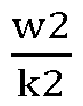
- For the fabrication process of the lithium ion battery, reference was overall made to example 5-1 except that the first polar substance PAM, the first reinforcing agent PVDF and the alumina had a mass ratio of 80:15:5. The second polar substance PEO, the second reinforcing agent PVDF and the alumina had a mass ratio of 84.2:15.8.
- The mass content w1 of the first polar substance in the first coating and the mass content k1 of the first reinforcing agent in the first coating had a mass ratio


- For the fabrication process of the lithium ion battery, reference was overall made to example 5-1 except that the first polar substance PAM, the first reinforcing agent PVDF and the alumina had a mass ratio of 80:13.3:6.7. The second polar substance PEO and the second reinforcing agent PVDF had a mass ratio of 86:14.
- The mass content w1 of the first polar substance in the first coating and the mass content k1 of the first reinforcing agent in the first coating had a mass ratio


- For the fabrication process of the lithium ion battery, reference was overall made to example 5-1 except that the first polar substance PAM, the first reinforcing agent PVDF and the alumina had a mass ratio of 80:10:10. The second polar substance PEO and the second reinforcing agent PVDF had a mass ratio of 89:11.
- The mass content w1 of the first polar substance in the first coating and the mass content k1 of the first reinforcing agent in the first coating had a mass ratio


- For the fabrication process of the lithium ion battery, reference was overall made to example 5-1 except that the first polar substance PAM, the first reinforcing agent PVDF and the alumina had a mass ratio of 80:8.9:11.1. The second polar substance PEO, the second reinforcing agent PVDF and the alumina had a mass ratio of 90:10.
- The mass content w1 of the first polar substance in the first coating and the mass content k1 of the first reinforcing agent in the first coating had a mass ratio


- For the fabrication process of the lithium ion battery, reference was overall made to example 5-1 except that the first polar substance PAM, the first reinforcing agent PVDF and the alumina had a mass ratio of 80:8.6:11.4. The second polar substance PEO and the second reinforcing agent PVDF had a mass ratio of 90.3:9.7.
- The mass content w1 of the first polar substance in the first coating and the mass content k1 of the first reinforcing agent in the first coating had a mass ratio


-
- 1) A first polar substance PEO and a first reinforcing agent PVDF were dissolved in NMP according to a mass ratio of 80:20, the mixture was stirred to be even to obtain first coating slurry, and a surface A of a PE base film (surface of the PE base film close to a positive electrode) was coated with the first coating slurry using a gravure coating method.
- 2) A second polar substance PEO and a first reinforcing agent PVDF were dissolved in deionized water according to a mass ratio of 80:20, the mixture was stirred to be even to obtain second coating slurry, and a surface B of the PE base film (surface of the PE base film close to a negative electrode) was coated with the second coating slurry using a gravure coating method.
- 3) The PE base film coated with the first coating slurry in step 1) and the second coating slurry in step 2) was dried at 60°C for 1h to form a first coating and a second coating on the two surfaces of the PE base film, and the separator was obtained.
- A positive active substance LiNi0.6Co0.2Mn0.2O2, a positive binder PVDF and conductive carbon were mixed according to a mass ratio of 97:1:2 and dissolved in NMP, the mixture was stirred for 6h to obtain positive slurry, aluminum foil was coated with the positive slurry, and drying and cold pressing were performed to obtain the positive electrode.
- SA and SBR were mixed according to a mass ratio of 80:20 to obtain a negative binder, a negative active substance (carbon-silicon mixture (C:Si=95:5, Si had a particle size of 0.05µm)), the negative binder and carbon nanotubes were mixed according to a mass ratio of 95.9:2.5:1.6 and dissolved in water, the mixture was stirred for 6h to obtain negative slurry, copper foil was coated with the negative slurry, and drying and cold pressing were performed to obtain the negative electrode.
- The positive electrode, the separator and the negative electrode were stacked in sequence, the first coating of the separator being in contact with the positive electrode, and the second coating of the separator being in contact with the negative electrode; and then, the positive electrode, the separator and the negative electrode were wound to obtain a bare cell. The bare cell was placed into an aluminum shell, a top cover was welded, and liquid injection, standing at a high temperature, formation, aging and other processes were performed to obtain the lithium ion battery.
- For the fabrication process of the lithium ion battery, reference was overall made to example 6-1 except that the negative active substance (carbon-silicon mixture (C:Si=95:5, Si had a particle size of 0.1µm)), the negative binder and the carbon nanotubes had a mass ratio of 96.7:2.5:0.8.
- This example was basically same as example 6-1 except that the negative active substance (carbon-silicon mixture (Si had a particle size of 0.3µm)), the negative binder and the carbon nanotubes had a mass ratio of 97:2.5:0.5.
- For the fabrication process of the lithium ion battery, reference was overall made to example 6-1 except that the negative active substance (carbon-silicon mixture (C:Si=95:5, Si had a particle size of 0.5µm)), the negative binder and the carbon nanotubes had a mass ratio of 96.8:2.5:0.7.
- For the fabrication process of the lithium ion battery, reference was overall made to example 6-1 except that the negative active substance (carbon-silicon mixture (Si had a particle size of 0.6µm)), the negative binder and the carbon nanotubes had a mass ratio of 96:2.5:1.5.
-
- 1) A first polar substance PEO and a first reinforcing agent PVDF were dissolved in NMP according to a mass ratio of 80:20, the mixture was stirred to be even to obtain first coating slurry, and a surface A of a PE base film (surface of the PE base film close to a positive electrode) was coated with the first coating slurry using a gravure coating method.
- 2) A second polar substance PEO and a first reinforcing agent PVDF were dissolved in deionized water according to a mass ratio of 80:20, the mixture was stirred to be even to obtain second coating slurry, and a surface B of the PE base film (surface of the PE base film close to a negative electrode) was coated with the second coating slurry using a gravure coating method.
- 3) The PE base film coated with the first coating slurry in step 1) and the second coating slurry in step 2) was dried at 60°C for 1h to form a first coating and a second coating on the two surfaces of the PE base film, and the separator was obtained.
- A positive active substance LiNi0.4Co0.4Mn0.2O2, a positive binder PVDF and conductive carbon were mixed according to a mass ratio of 97:1:2 and dissolved in NMP, the mixture was stirred for 6h to obtain positive slurry, aluminum foil was coated with the positive slurry, and drying and cold pressing were performed to obtain the positive electrode.
- SA and SBR were mixed according to a mass ratio of 80:20 to obtain a negative binder, a negative active substance (carbon-silicon mixture (C:Si=95:5, Si had a particle size of 0.3µm)), the negative binder and carbon nanotubes were mixed according to a mass ratio of 97:2.5:0.5 and dissolved in water, the mixture was stirred for 6h to obtain negative slurry, copper foil was coated with the negative slurry, and drying and cold pressing were performed to obtain the negative electrode.
- The positive electrode, the separator and the negative electrode were stacked in sequence, the first coating of the separator being in contact with the positive electrode, and the second coating of the separator being in contact with the negative electrode; and then, the positive electrode, the separator and the negative electrode were wound to obtain a bare cell. The bare cell was placed into an aluminum shell, a top cover was welded, and liquid injection, standing at a high temperature, formation, aging and other processes were performed to obtain the lithium ion battery.
- For the fabrication process of the lithium ion battery, reference was overall made to example 7-1 except that the positive active substance was LiNi0.5Co0.2Mn0.3O2.
- For the fabrication process of the lithium ion battery, reference was overall made to example 7-1 except that the positive active substance was LiNi0.6Co0.2Mn0.2O2.
- For the fabrication process of the lithium ion battery, reference was overall made to example 7-1 except that the positive active substance was LiNi0.8Co0.1Mn0.1O2.
- For the fabrication process of the lithium ion battery, reference was overall made to example 7-1 except that the positive active substance was LiNi0.9Co0.05Mn0.05O2.
-
- 1) PEO and PAM were mixed according to a mass ratio of 1.8:1 to obtain a first polar substance, the first polar substance and a first reinforcing agent PVDF were dissolved in NMP according to a mass ratio of 80:20, the mixture was stirred to be even to obtain first coating slurry, and a surface A of a PE base film (surface of the PE base film close to a positive electrode) was coated with the first coating slurry using a gravure coating method.
- 2) PEI and PEO were mixed according to a mass ratio of 1.8:1 to obtain a second polar substance, the second polar substance and a first reinforcing agent PVDF were dissolved in deionized water according to a mass ratio of 80:20, the mixture was stirred to be even to obtain second coating slurry, and a surface B of the PE base film (surface of the PE base film close to a negative electrode) was coated with the second coating slurry using a gravure coating method.
- 3) The PE base film coated with the first coating slurry in step 1) and the second coating slurry in step 2) was dried at 60°C for 1h to form a first coating and a second coating on the two surfaces of the PE base film, and the separator was obtained.
- A positive active substance LiNi0.4Co0.4Mn0.4O2, a positive binder PVDF and conductive carbon were mixed according to a mass ratio of 97:1:2 and dissolved in NMP, the mixture was stirred for 6h to obtain positive slurry, aluminum foil was coated with the positive slurry, and drying and cold pressing were performed to obtain the positive electrode.
- SA and SBR were mixed according to a mass ratio of 80:20 to obtain a negative binder, a negative active substance (carbon-silicon mixture (C:Si=95:5, Si had a particle size of 0.3µm)), the negative binder and carbon nanotubes were mixed according to a mass ratio of 97:2.5:0.5 and dissolved in water, the mixture was stirred for 6h to obtain negative slurry, copper foil was coated with the negative slurry, and drying and cold pressing were performed to obtain the negative electrode.
- The positive electrode, the separator and the negative electrode were stacked in sequence, the first coating of the separator being in contact with the positive electrode, and the second coating of the separator being in contact with the negative electrode; and then, the positive electrode, the separator and the negative electrode were wound to obtain a bare cell. The bare cell was placed into an aluminum shell, a top cover was welded, and liquid injection, standing at a high temperature, formation, aging and other processes were performed to obtain the lithium ion battery.
- For the fabrication process of the lithium ion battery, reference was overall made to example 8-1 except that the PEO and the PAM had a mass ratio of 2:1 in the first polar substance, and the PEI and the PEO had a mass ratio of 2:1 in the second polar substance.
- For the fabrication process of the lithium ion battery, reference was overall made to example 8-1 except that the PEO and the PAM had a mass ratio of 3:1 in the first polar substance, and the PEI and the PEO had a mass ratio of 3:1 in the second polar substance.
- For the fabrication process of the lithium ion battery, reference was overall made to example 8-1 except that the PEO and the PAM had a mass ratio of 4.5:1 in the first polar substance, and the PEI and the PEO had a mass ratio of 4.5:1 in the second polar substance.
- For the fabrication process of the lithium ion battery, reference was overall made to example 8-1 except that the PEO and the PAM had a mass ratio of 5:1 in the first polar substance, and the PEI and the PEO had a mass ratio of 5:1 in the second polar substance.
- For the fabrication process of the lithium ion battery, reference was overall made to example 8-1 except that the PEO and the PAM had a mass ratio of 6:1 in the first polar substance, and the PEI and the PEO had a mass ratio of 6:1 in the second polar substance.
- For the fabrication process of the lithium ion battery, reference was overall made to example 8-1 except that the PEO and the PAM had a mass ratio of 6.3:1 in the first polar substance, and the PEI and the PEO had a mass ratio of 6.3:1 in the second polar substance.
- For the fabrication process of the lithium ion battery, reference was overall made to Examples 1-2 except that the first polar substance PEO and the second polar substance PEI were not contained.
- For the fabrication process of the lithium ion battery, reference was overall made to Examples 1-2 except that the first polar substance PEO was not included, and the second polar substance PEI had a proportion of 100% in the second coating.
- For the fabrication process of the lithium ion battery, reference was overall made to Examples 1-2 except that the second polar substance PEI was not included, and the first polar substance PEO had a proportion of 100% in the first coating.
- The separators of an example and a comparative example were cut into test samples having a length of 100mm and a width of 10mm. A stainless steel plate with a width of 25mm was taken, double-sided adhesive tape (with a width of 11mm) was pasted, the test sample was pasted to the double-sided adhesive tape on the stainless steel plate, and a press roller of 2,000g was used for rolling back and forth three times (300mm/min) on a surface of the test sample. The test sample was bent by 180 degrees, an organic-inorganic mixed layer and the base film of the test sample were manually peeled by 25mm, the test sample was fixed on a testing machine (such as INSTRON 336) to keep the peeling surface and a force line of the testing machine consistent, the testing machine performed continuous peeling at 30mm/min to obtain a peeling force curve, an average value of a stable section was taken as a peeling force F0, and a binding force F between the organic-inorganic mixed layer and a current collector in the test sample was calculated by the following formula. F=F0/width of test sample (unit of F: N/m).
- The test was performed according to the standard GB/T6040-2002 "Infrared Spectrum Analysis Method" using an IS10 Fourier transform infrared spectrometer of Thermo Nicolet Corporation. The positive slurry obtained in the example and the comparative example was subjected to suction filtration to obtain positive powder; the PE base film was coated with the first coating slurry obtained in the example and the comparative example, and the PE base film was removed after suction filtration to obtain first coating powder. The positive powder and the first coating powder were mixed and further dried to obtain mixed powder; an infrared test was performed on the mixed powder. The infrared test method between the second coating and the negative electrode was same as the above method.
- 3. Normal temperature cycle performance: the batteries of all the examples and comparative examples were subjected to constant-current and constant-voltage charging at a charging current of 1C in a 25°C environment until an upper limit voltage was 4.35V. Then, constant-current discharge was performed at a discharge current of 1C until a final voltage was 2.8V, and a first discharge capacity value C0 at this point was recorded. The batteries of all the examples and comparative examples were then charged at a voltage of 3.3V to 4.3V at 0.33C0 and discharged at 1C0, this process was repeated continuously, and a discharge capacity Cn after 1,000 cycles was recorded. Capacity conservation rate at 1,000th cycle=(discharge capacity at 1,000th cycle/discharge capacity at first cycle)×100%.
- 4. High-rate discharge capacity: the batteries of all the examples and comparative examples were subjected to constant-current and constant-voltage charging at a charging current of 1/3C in a 25°C environment until an upper limit voltage was 4.35V. Then, constant-current discharge was performed at discharge currents of 1/3C, 3C and 5C until the final voltage was 2.8V, and a discharge capacity value at this point was recorded.
- 5. Method for testing cycle expansion rate of winding assembly
- A thickness of the bare cell after hot pressing was measured using a vernier caliper, and after 1,000 cycles, the cell was disassembled to measure the thickness of the bare cell, expansion rate=(diameter of bare cell after cycle-diameter of bare cell before cycle)/thickness of bare cell before cycle.
- Test results of related parameters and performances of the batteries of the above Examples 1-1 to 1-7 are shown in Table 1 below.
Table 1. Test results of parameters and performances of Examples 1-1 to 1-7 Separator, positive electrode and negative electrode Battery performance First coating and positive electrode Second coating and negative electrode First polar substanc e w1 Positiv e binder m1 
Peelin 9 force (N) Second polar substanc e w2 Negativ e binder m2 
Peelin 9 force (N) 
Cycle expansio n rate Capacity conservati on rate after 1,000 cycles 5C discharg e capacity (Ah) S1 -1 PEO 80 % PVDF 1.07 % 75:1 0.075 PEI 80 % SA+SB R 2.66 % 30: 1 0.085 1:0.9 4 1.7% 81.2% 153.1 S1 -2 PEO 80 % PVDF 1% 80:1 0.085 PEI 80 % SA+SB R 2.5% 32: 1 0.092 1:1 1.5% 84.6% 159.4 S1 -3 PEO 80 % PVDF 0.91 % 87:1 0.090 PEI 80 % SA+SB R 2.2% 36: 1 0.1 1:1.0 6 1.2% 87.0% 165.2 S1 -4 PEO 80 % PVDF 0.86 % 93:1 0.095 PEI 80 % SA+SB R 2% 40: 1 0.111 1:1.0 9 1.1% 88.1% 171.1 S1-5 PEO 80% PVDF 0.82 % 97:1 0.085 PEI 80 % SA+SBR 1.77 % 45:1 0.098 1:1.15 1.4% 86.2% 163.5 S1 -6 PEO 80 % PVDF 0.8% 100: 1 0.083 PEI 80 % SA+SB R 1.6% 50: 1 0.09 1:1.2 1 1.5% 83.7% 157.3 S1 -7 PEO 80 % PVDF 0.76 105: 1 0.08 PEI 80 % SA+SB R 1.5% 53: 1 0.083 1:1.2 5 1.6% 82.1% 155.4 - Test results of related parameters and performances of the batteries of the above Examples 2-1 to 2-4 are shown in Table 2 below.
Table 2. Test results of parameters and performances of Examples 2-1 to 2-4 Separator, positive electrode and negative electrode Battery performance First coating and positive electrode Second coating and negative electrode First polar substanc e w1 Positiv e binder m1 
Peelin 9 force (N) Second polar substanc e w2 Negativ e binder m2 
Peelin 9 force (N) 
Cycle expansio n rate Capacity conservati on rate after 1,000 cycles 5C discharg e capacity (Ah) S2 -1 PAM 96.8 % PVDF 1 % 96.8: 1 0.076 PEO 77.5 % SA+SB R 2.5 % 31: 1 0.075 1:0. 8 1.6% 85.6% 158.2 S2 -2 PAM 85 % PVDF 1 % 85:1 0.086 PEO 85% SA+SB R 2.5 % 34: 1 0.098 1:1 1.2% 87.2% 167.2 S2 -3 PAM 71.1 % PVDF 1 % 71.1: 1 0.079 PEO 92.5 % SA+SB R 2.5 % 37: 1 0.081 1:1. 3 1.3% 86.0% 163.1 S2 -4 PAM 65 % PVDF 1 % 65:1 0.077 PEO 97.5 % SA+SB R 2.5 % 39: 1 0.076 1:1. 5 1.5% 85.8% 160.5 - Test results of related parameters and performances of the batteries of the above Examples 3-1 to 3-5 are shown in Table 3 below.
Table 3. Test results of parameters and performances of Examples 3-1 to 3-5 Separator, positive electrode and negative electrode Battery performance First coating and positive electrode Second coating and negative electrode First polar substanc e w1 Positiv e binder m1 
Peelin 9 force (N) Second polar substanc e w2 Negativ e binder m2 
Peelin 9 force (N) 
Cycle expansio n rate Capacity conservatio n rate after 1,000 cycles 5C discharg e capacity (Ah) S3 -1 Polyurea 75 % PVDF 0.8 % 93.7: 1 0.075 PAM 75 % SA+SB R 1.8 % 41.6: 1 0.078 1: 1 1.8% 78.2% 148.3 S3 -2 Polyurea 80 % PVDF 0.9 % 88.8: 1 0.078 PAM 80 % SA+SB R 2% 40:1 0.079 1: 1 1.5% 82.0% 159.5 S3 -3 Polyurea 85 % PVDF 1% 85:1 0.080 PAM 85 % SA+SB R 2.6 % 32.6: 1 0.083 1: 1 1.4% 84.1% 164.2 S3 -4 Polyurea 90 % PVDF 1.2 % 75:1 0.077 PAM 90 % SA+SB R 3% 30:1 0.080 1: 1 1.6% 80.8% 155.3 S3 -5 Polyurea 92 % PVDF 1.5 % 61.3: 1 0.076 PAM 92 % SA+SB R 3.2 % 28.8: 1 0.077 1: 1 1.7% 79.4% 150.3 - Test results of related parameters and performances of the batteries of the above Examples 4-1 to 4-5 are shown in Table 4 below.

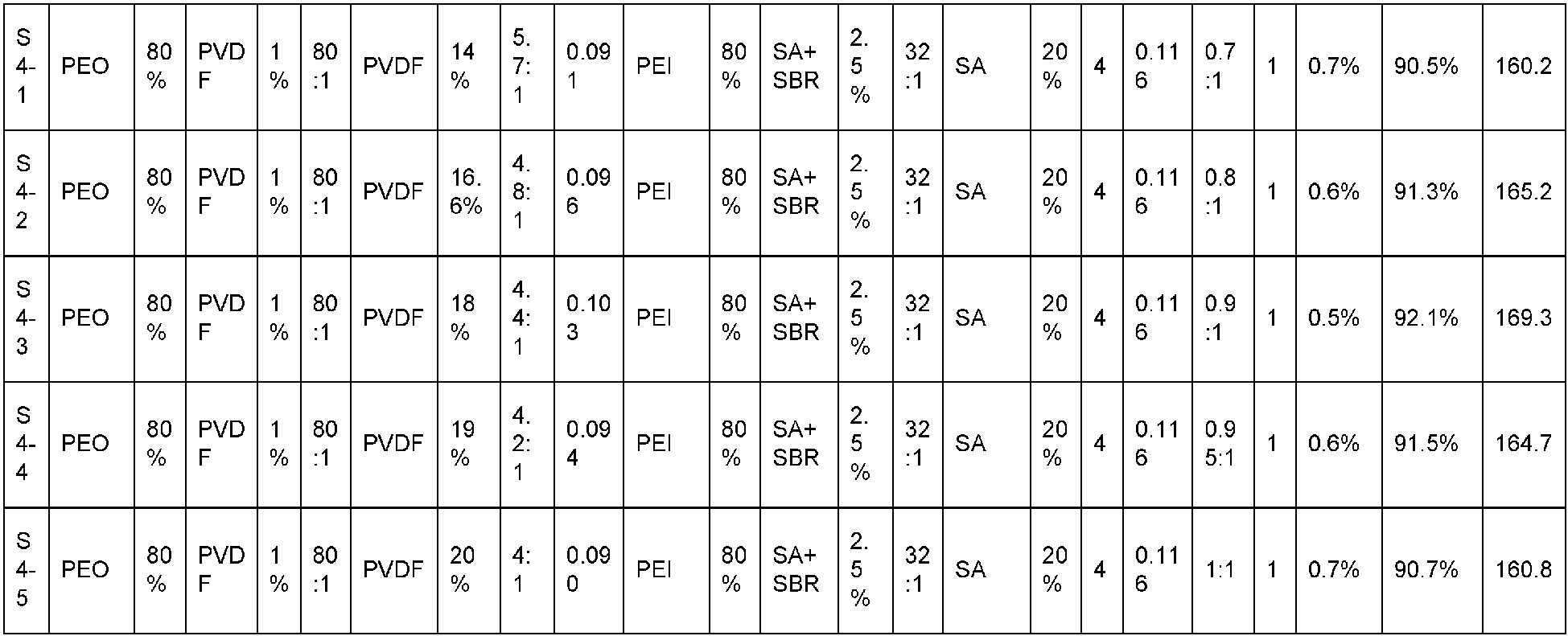
- Test results of related parameters and performances of the batteries of the above Examples 5-1 to 5-7 are shown in Table 5 below.


- Test results of related parameters and performances of the batteries of the above Examples 6-1 to 6-5 are shown in Table 6 below.


- Test results of related parameters and performances of the batteries of the above Examples 7-1 to 7-5 are shown in Table 7 below.


- Test results of related parameters and performances of the batteries of the above Examples 8-1 to 8-7 are shown in Table 8 below.


- Test results of related parameters and performances of the batteries of the above Comparative Examples 1 to 3 are shown in Table 9 below.


- From the above results, in Table 1,


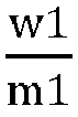


- In Table 2,


- In Table 3, when a value of

- In Table 4, in Examples 4-1 to 4-5, good results of the battery performances, such as the cycle expansion rate, the capacity conservation rate after 1,000 cycles and the 5C discharge capacity, are obtained by adjusting the mass ratio of the mass content k1 of the first reinforcing agent in the first coating to the mass content k2 of the second reinforcing agent in the second coating, and particularly when

- In Table 5, in Examples 5-1 to 5-7, by adjusting the mass ratio


- In Table 6, Examples 6-1 to 6-5 reflect influences of the particle size of silicon on the battery performance. Good results of the battery performances, such as the cycle expansion rate, the capacity conservation rate after 1,000 cycles and the 5C discharge capacity, are obtained, and particularly when the particle size of silicon ranges from 0.1 microns to 0.5 microns, the battery performance is better.
- In Table 7, in Examples 7-1 to 7-4, the expansion of the bare cell may be significantly improved by adjusting the content of Ni in the ternary positive material, good results of the battery performances, such as the cycle expansion rate and the capacity conservation rate after 1,000 cycles, are obtained, and particularly the Ni content ranges from 0.5 to 0.9, the battery performance is better.
- In Table 8, in Examples 8-1 to 8-7, good results of the battery performances, such as the cycle expansion rate, the capacity conservation rate after 1,000 cycles and the 5C discharge capacity, are obtained by adjusting the mass ratio C1 of the polyethylene oxide to the polyacrylamide and the mass ratio C2 of the polyethylene imine to the polyethylene oxide, and particularly when values of C1 and C2 are (2-6):1, the battery performance is better.
- In contrast, in Table 9, in Comparative Examples 1 to 3, the battery performances, such as the cycle expansion rate, the capacity conservation rate after 1,000 cycles and the 5C discharge capacity, are not effectively improved.
- Furthermore, as shown in
FIG. 1 , the first polar substance is PEO, the first reinforcing agent is PVDF, the positive binder is PEO, the second polar substance is PEI, the second reinforcing agent is PVDF, the negative binders are SA and SBR, and the negative active substance is a carbon-silicon mixture. - Between the positive electrode and the separator, F on the positive binder PVDF and H of the first polar substance PEO form a hydrogen bond.
- In the first coating, F on the first reinforcing agent PVDF and H of the first polar substance PEO form a hydrogen bond.
- Between the negative electrode and the separator, since electronegativity of N is lower than electronegativity of O which is lower than electronegativity of F, H on -OH in the carbon-silicon mixture is more electron-deficient than H of - NH2, and therefore, the hydrogen bond is easily formed between N on -NH2 in the second polar substance PEI and H on -OH in the carbon-silicon mixture. Similarly, a hydrogen bond is formed between N on -NH2 in the second polar substance PEI and H on -COOH in the negative binder SA. A hydrogen bond may be formed between H on -OH in the carbon-silicon mixture and H on - COOH in SA.
- In the second coating, a hydrogen bond is formed between F of the second reinforcing agent PVDF and H of the PEI.
- As shown in
FIG. 2 , a peak of the hydrogen bond exists between 3,200cm-1 and 3,600cm-1, and when the first polar substance or the second polar substance is not added in Comparative Example 1, the hydrogen bond is hardly generated, but in Example 1, the peak is broad and obvious due to hydrogen bond connection on the surfaces A and B. In addition, it should be noted that four hydrogen bonds of O-H-O, F-H-O, N-H-O and F-H-N are ordered into F-H-O, F-H-N, O-H-O and N-H-O in a descending order of bond energy, the bond energy has a small difference between 25KJ/mol and 40KJ/mol, a plurality of hydrogen bonds exist in one wavenumber range, and normally, the more the hydrogen bonds are, the more the displayed peaks are, and the wider the peaks are. - It should be noted that the present application is not limited to the above embodiments. The above-mentioned embodiments are merely examples, and embodiments having substantially the same configuration as the technical idea and exerting the same effects within the scope of the technical solution of the present application are all included in the technical scope of the present application. Furthermore, other embodiments configured by applying various modifications that can be conceived by those skilled in the art to the embodiments and combining some constituent elements in the embodiments are also included in the scope of the present application without departing from the scope of the gist of the present application.
Claims (17)
- A battery, characterized by comprising:a positive electrode, a separator and a negative electrode, wherein the separator comprises a base film, a first coating provided on a first surface of the base film, and a second coating provided on a second surface of the base film, whereinthe first coating comprises a first polar substance, the first polar substance comprises one or more of polyolefin amide substances, polyolefin imine substances, polyolefin oxide substances, polyurethane substances and polyurea substances, and hydrogen bonds are formed between the first polar substance and a positive binder of the positive electrode; andthe second coating comprises a second polar substance, the second polar substance comprises one or more of polyolefin amide substances, polyolefin imine substances, polyolefin oxide substances, polyurethane substances and polyurea substances, and hydrogen bonds are formed between the second polar substance and a negative binder and/or a negative active component of the negative electrode.
- The battery according to claim 1,
wherein a peeling force between the first coating and the positive electrode is not lower than 0.075N, optionally 0.075N-0.125N; a peeling force between the second coating and the negative electrode is not lower than 0.075N, optionally 0.075N-0.15N. - The battery according to any one of claim 1 or 2,wherein a mass content w1 of the first polar substance in the first coating and a mass content m1 of the positive binder in a positive film layer have a ratio
 a mass content w2 of the second polar substance in the second coating and a mass content m2 of the negative binder in a negative film layer have a ratio
- The battery according to any one of claims 1 to 3,
wherein a mass content w1 of the first polar substance in the first coating and a mass content w2 of the second polar substance in the second coating have a ratio
- The battery according to any one of claims 1 to 4,wherein the first polar substance has a mass content w1 of 80%-90% in the first coating, and the positive binder has a mass content m1 of 0.9%-1.2% in a positive film layer; andthe second polar substance has a mass content w2 of 80%-90% in the second coating, and the negative binder has a mass content m2 of 2%-3% in a negative film layer.
- The battery according to any one of claims 1 to 5,wherein the first polar substance comprises polyethylene oxide and polyacrylamide; the polyethylene oxide and the polyacrylamide have a mass ratio C1 of (2-6):1; andthe second polar substance comprises polyethylene imine and polyethylene oxide; the polyethylene imine and the polyethylene oxide have a mass ratio C2 of (2-6):1.
- The battery according to any one of claims 1 to 6,
wherein the first coating comprises a first reinforcing agent, and a mass content w1 of the first polar substance in the first coating and a mass content k1 of the first reinforcing agent in the first coating have a mass ratio

- The battery according to claim 7,
wherein the mass content k1 of the first reinforcing agent in the first coating is not higher than the mass content k2 of the second reinforcing agent in the second coating. - The battery according to claim 7,
wherein the mass content k1 of the first reinforcing agent in the first coating and the mass content k2 of the second reinforcing agent in the second coating have a ratio
- The battery according to claim 7,wherein the first reinforcing agent or the second reinforcing agent comprises one or more of polyvinylidene difluoride and sodium alginate; andthe positive binder comprises polyvinylidene fluoride, and the negative binder comprises more than one of styrene butadiene rubber and sodium alginate.
- The battery according to any one of claims 1 to 10,
wherein the negative active component comprises a silicon-carbon mixture, silicon in the silicon-carbon mixture has a particle size of 0.1-0.5 microns, carbon in the silicon-carbon mixture is mixed carbon of artificial graphite and natural graphite, and the silicon-carbon mixture has a content of 95%-97% in a negative film layer. - The battery according to any one of claims 1 to 11,
wherein the first coating and the second coating have a mass ratio of 1:(1-1.5). - The battery according to claim 7,wherein the first coating is prepared from first coating slurry, and the first coating slurry comprises the first polar substance, the first reinforcing agent and a first solvent,wherein the first coating slurry has a viscosity of 8,000mpa.s-12,000mpa.s; andthe second coating is prepared from second coating slurry, and the second coating slurry comprises the second polar substance, the second reinforcing agent and a second solvent;wherein the second coating slurry has a viscosity of 5,000mpa.s-20,000mpa.s.
- The battery according to any one of claims 1 to 13,
wherein the positive electrode comprises a positive material LiNixCoyMnzO2, where x+y+z=1, and x=0.5-0.9, optionally, x=0.5-0.7 or x=0.8-0.9. - A battery module, characterized by comprising the battery according to any one of claims 1 to 14.
- A battery pack, characterized by comprising the battery module according to claim 15.
- An electric device, characterized by comprising more than one of the battery according to any one of claims 1 to 14, the battery module according to claim 15 and the battery pack according to claim 16.
Applications Claiming Priority (1)
| Application Number | Priority Date | Filing Date | Title |
|---|---|---|---|
| PCT/CN2021/108971 WO2023004633A1 (en) | 2021-07-28 | 2021-07-28 | Battery, battery module, battery pack, and electrical device |
Publications (2)
| Publication Number | Publication Date |
|---|---|
| EP4148891A1 true EP4148891A1 (en) | 2023-03-15 |
| EP4148891A4 EP4148891A4 (en) | 2024-06-19 |
Family
ID=85086116
Family Applications (1)
| Application Number | Title | Priority Date | Filing Date |
|---|---|---|---|
| EP21927065.9A Pending EP4148891A4 (en) | 2021-07-28 | 2021-07-28 | Battery, battery module, battery pack, and electrical device |
Country Status (6)
| Country | Link |
|---|---|
| US (1) | US12148949B2 (en) |
| EP (1) | EP4148891A4 (en) |
| JP (1) | JP7432753B2 (en) |
| KR (1) | KR102759598B1 (en) |
| CN (1) | CN116349077B (en) |
| WO (1) | WO2023004633A1 (en) |
Families Citing this family (4)
| Publication number | Priority date | Publication date | Assignee | Title |
|---|---|---|---|---|
| EP4629428A4 (en) * | 2023-04-17 | 2026-04-01 | Contemporary Amperex Technology Co Ltd | INSULATION FILM, BATTERY CELL, BATTERY AND ELECTRICAL DEVICE |
| CN116799437B (en) * | 2023-08-18 | 2023-10-31 | 荣耀终端有限公司 | Battery and electronic equipment |
| WO2026000294A1 (en) * | 2024-06-27 | 2026-01-02 | 深圳市星源材质科技股份有限公司 | Separator, preparation method therefor, and use thereof |
| CN118610475A (en) * | 2024-06-28 | 2024-09-06 | 江阴纳力新材料科技有限公司 | A modified current collector base film and its preparation method and application |
Family Cites Families (31)
| Publication number | Priority date | Publication date | Assignee | Title |
|---|---|---|---|---|
| US7820320B2 (en) * | 2001-08-20 | 2010-10-26 | Power Paper Ltd. | Method of making a thin layer electrochemical cell with self-formed separator |
| KR100859755B1 (en) * | 2007-02-07 | 2008-09-24 | 한국과학기술원 | Li / SOCl2 battery including separator for battery coated with polyurethane-based polymer compound |
| KR101845117B1 (en) * | 2010-12-14 | 2018-04-03 | 교리쯔 가가꾸 산교 가부시키가이샤 | Battery electrode or separator surface protective agent, battery electrode or separator protected by same, and battery having battery electrode or separator |
| US9450223B2 (en) * | 2012-02-06 | 2016-09-20 | Samsung Sdi Co., Ltd. | Lithium secondary battery |
| JP6523609B2 (en) * | 2013-03-26 | 2019-06-05 | 株式会社東芝 | Electrode for non-aqueous electrolyte battery, non-aqueous electrolyte secondary battery and battery pack |
| KR102210881B1 (en) * | 2013-04-16 | 2021-02-03 | 삼성에스디아이 주식회사 | Seaparator and lithium battery containing the separator |
| CN103247770A (en) * | 2013-04-25 | 2013-08-14 | 东莞新能源科技有限公司 | A kind of lithium-ion battery diaphragm and preparation method thereof |
| KR20150122293A (en) * | 2014-04-22 | 2015-11-02 | 에스케이이노베이션 주식회사 | Anode binder for secondary battery, electrode for secondary battery and secondary battery comprising the same |
| EP3809509B1 (en) * | 2015-05-11 | 2022-07-27 | Contemporary Amperex Technology Co., Limited | Composite diaphragm and lithium ion battery using same |
| US10243188B2 (en) * | 2015-06-09 | 2019-03-26 | GM Global Technology Operations LLC | Separator for lithium-based batteries |
| CN107925086B (en) * | 2015-08-14 | 2020-10-09 | 旭化成株式会社 | Electrode for electrochemical element |
| KR102019838B1 (en) * | 2015-09-30 | 2019-09-10 | 주식회사 엘지화학 | Lithium secondary battery comprising non-aqueous liquid electrolyte |
| CN105591055A (en) * | 2015-12-17 | 2016-05-18 | 中南大学 | High-multiplying power lithium ion battery and preparation method thereof |
| US10224528B2 (en) * | 2016-06-17 | 2019-03-05 | Bosch Battery Systems Llc | Battery assembly including spacer |
| CN109792020B (en) * | 2017-01-06 | 2022-08-26 | 株式会社Lg新能源 | Battery separator including functional binder and electrochemical device including the same |
| JP6779157B2 (en) | 2017-02-22 | 2020-11-04 | 帝人株式会社 | Separator for non-aqueous secondary battery and non-aqueous secondary battery |
| KR102231395B1 (en) * | 2017-03-17 | 2021-03-24 | 도레이 카부시키가이샤 | Battery separator, electrode body and non-aqueous electrolyte secondary battery |
| TW201912736A (en) * | 2017-09-11 | 2019-04-01 | 日商可樂麗股份有限公司 | Coating liquid for separator for non-aqueous electrolyte battery, and separator for non-aqueous electrolyte battery and non-aqueous electrolyte battery using the same |
| CN109841783A (en) * | 2017-11-28 | 2019-06-04 | 宁德时代新能源科技股份有限公司 | Lithium ion battery and isolating membrane thereof |
| CN110197922B (en) * | 2018-02-26 | 2021-03-19 | 宁德新能源科技有限公司 | Separator and Lithium Ion Batteries |
| KR20180048554A (en) * | 2018-05-03 | 2018-05-10 | 인천대학교 산학협력단 | Polymeric binder for anodes using interaction between polyacrylic acid and polyaniline |
| CN109698354B (en) * | 2018-12-26 | 2021-03-23 | 中国科学院过程工程研究所 | A binder, negative electrode slurry using the same, and preparation method and application thereof |
| KR102342671B1 (en) * | 2019-01-04 | 2021-12-22 | 삼성에스디아이 주식회사 | Separator for rechargeable lithium battery and rechargeable lithium battery including the same |
| TW202044646A (en) | 2019-04-04 | 2020-12-01 | 美商希爾格得有限公司 | Polyamide-imide coated separators for high energy rechargeable lithium batteries |
| KR102376449B1 (en) * | 2019-04-30 | 2022-03-18 | 삼성에스디아이 주식회사 | Separator for rechargeable lithium battery and rechargeable lithium battery including the same |
| CN110970591B (en) * | 2019-12-18 | 2021-05-04 | 江苏厚生新能源科技有限公司 | Coating slurry with high adhesion and high ion conductivity and preparation method, lithium battery separator |
| KR102580238B1 (en) * | 2020-03-10 | 2023-09-19 | 삼성에스디아이 주식회사 | Coating Composition for Separator, Method for preparing Separator, Seaparator, and Lithium battery comprising the Separator |
| CN111403664A (en) | 2020-03-24 | 2020-07-10 | 珠海冠宇动力电池有限公司 | A kind of polyphenylurea separator and preparation method thereof and lithium ion battery |
| CN111370761B (en) * | 2020-03-25 | 2021-08-20 | 中航锂电技术研究院有限公司 | PEO film and preparation method thereof and solid-state battery |
| CN112928386B (en) * | 2021-01-22 | 2022-06-17 | 江苏厚生新能源科技有限公司 | A kind of functional coating and its preparation method and application |
| CN113061209A (en) * | 2021-03-15 | 2021-07-02 | 珠海冠宇电池股份有限公司 | Binder and lithium ion battery comprising same |
-
2021
- 2021-07-28 WO PCT/CN2021/108971 patent/WO2023004633A1/en not_active Ceased
- 2021-07-28 CN CN202180071500.2A patent/CN116349077B/en active Active
- 2021-07-28 EP EP21927065.9A patent/EP4148891A4/en active Pending
- 2021-07-28 JP JP2022550822A patent/JP7432753B2/en active Active
- 2021-07-28 KR KR1020227029101A patent/KR102759598B1/en active Active
-
2022
- 2022-10-03 US US17/937,768 patent/US12148949B2/en active Active
Also Published As
| Publication number | Publication date |
|---|---|
| JP7432753B2 (en) | 2024-02-16 |
| US12148949B2 (en) | 2024-11-19 |
| CN116349077A (en) | 2023-06-27 |
| US20230117614A1 (en) | 2023-04-20 |
| KR20230019406A (en) | 2023-02-08 |
| CN116349077B (en) | 2025-07-08 |
| WO2023004633A1 (en) | 2023-02-02 |
| JP2023538163A (en) | 2023-09-07 |
| EP4148891A4 (en) | 2024-06-19 |
| KR102759598B1 (en) | 2025-01-24 |
Similar Documents
| Publication | Publication Date | Title |
|---|---|---|
| EP4148891A1 (en) | Battery, battery module, battery pack, and electrical device | |
| KR102816342B1 (en) | Secondary battery and device containing secondary battery | |
| EP4024533B1 (en) | Binder composition and preparation method for secondary battery | |
| US11962003B2 (en) | Negative electrode active material for lithium secondary battery, and negative electrode and lithium secondary battery including the same | |
| EP4421889A1 (en) | Positive electrode plate, secondary battery, battery module, battery pack, and power consuming device | |
| CN116435504A (en) | Electrode pole piece and its preparation method, secondary battery, battery module and battery pack | |
| EP4343881A1 (en) | Undercoat adhesive for dry-method electrode and preparation method therefor, composite current collector, battery electrode plate, secondary battery, battery module, battery pack and electric device | |
| EP4287331A1 (en) | Secondary battery, battery module, battery pack, and electrical device | |
| EP4210132A1 (en) | Electrode assembly, secondary battery, battery module, battery pack, and electrical device | |
| EP4418390A1 (en) | Membrane and preparation method therefor, secondary battery, battery module, battery pack, and power consumption device | |
| EP4550456A1 (en) | Composite negative electrode active material and preparation method therefor, negative electrode sheet comprising composite negative electrode active material, secondary battery, and electrical device | |
| CN116830319A (en) | Negative electrode plates, secondary batteries and electrical devices | |
| EP4231404A1 (en) | Composite electrolyte and solid-state battery comprising same | |
| CN115133030A (en) | Anode plate of lithium ion battery and its application | |
| EP4372049A1 (en) | Binder composition and isolation film comprising same | |
| EP4195349B1 (en) | Secondary battery | |
| EP4280298A1 (en) | Secondary battery having long service life, battery module, battery pack, and electric apparatus | |
| EP4550437A1 (en) | Negative pole piece, secondary battery, battery module, battery pack, and electrical device | |
| EP4672416A1 (en) | ELECTROCHEMICAL DEVICE AND ELECTRICAL DEVICE | |
| WO2024259956A1 (en) | Preparation method for positive electrode sheet, positive electrode sheet, battery cell, battery and electrical device | |
| EP4243144A1 (en) | Secondary battery | |
| CN119153634B (en) | Composite positive electrode material and preparation method thereof, positive electrode sheet containing same, battery and electric device | |
| US12191523B2 (en) | Polymer-modified porous material, membrane electrode, secondary battery, and electric device | |
| EP4318726A1 (en) | Secondary battery and preparation method therefor, and battery module, battery pack and electric apparatus | |
| EP4510265A1 (en) | Electrolyte solution, secondary battery, battery module, battery pack, and electric device |
Legal Events
| Date | Code | Title | Description |
|---|---|---|---|
| STAA | Information on the status of an ep patent application or granted ep patent |
Free format text: STATUS: UNKNOWN |
|
| STAA | Information on the status of an ep patent application or granted ep patent |
Free format text: STATUS: THE INTERNATIONAL PUBLICATION HAS BEEN MADE |
|
| PUAI | Public reference made under article 153(3) epc to a published international application that has entered the european phase |
Free format text: ORIGINAL CODE: 0009012 |
|
| STAA | Information on the status of an ep patent application or granted ep patent |
Free format text: STATUS: REQUEST FOR EXAMINATION WAS MADE |
|
| 17P | Request for examination filed |
Effective date: 20221010 |
|
| AK | Designated contracting states |
Kind code of ref document: A1 Designated state(s): AL AT BE BG CH CY CZ DE DK EE ES FI FR GB GR HR HU IE IS IT LI LT LU LV MC MK MT NL NO PL PT RO RS SE SI SK SM TR |
|
| A4 | Supplementary search report drawn up and despatched |
Effective date: 20240521 |
|
| RIC1 | Information provided on ipc code assigned before grant |
Ipc: H01M 50/489 20210101ALI20240514BHEP Ipc: H01M 50/46 20210101ALI20240514BHEP Ipc: H01M 50/457 20210101ALI20240514BHEP Ipc: H01M 50/417 20210101ALI20240514BHEP Ipc: H01M 50/414 20210101ALI20240514BHEP Ipc: H01M 50/204 20210101ALI20240514BHEP Ipc: H01M 4/587 20100101ALI20240514BHEP Ipc: H01M 4/525 20100101ALI20240514BHEP Ipc: H01M 4/505 20100101ALI20240514BHEP Ipc: H01M 4/38 20060101ALI20240514BHEP Ipc: H01M 4/36 20060101ALI20240514BHEP Ipc: H01M 4/04 20060101ALI20240514BHEP Ipc: H01M 50/423 20210101ALI20240514BHEP Ipc: H01M 4/62 20060101ALI20240514BHEP Ipc: H01M 50/409 20210101ALI20240514BHEP Ipc: H01M 10/0525 20100101ALI20240514BHEP Ipc: H01M 10/052 20100101ALI20240514BHEP Ipc: H01M 50/446 20210101ALI20240514BHEP Ipc: H01M 50/403 20210101ALI20240514BHEP Ipc: H01M 50/443 20210101AFI20240514BHEP |
|
| RAP1 | Party data changed (applicant data changed or rights of an application transferred) |
Owner name: CONTEMPORARY AMPEREX TECHNOLOGY(HONG KONG) LIMITED |
|
| DAV | Request for validation of the european patent (deleted) | ||
| DAX | Request for extension of the european patent (deleted) |