EP4148886A1 - Secondary battery and method for manufacturing same - Google Patents
Secondary battery and method for manufacturing same Download PDFInfo
- Publication number
- EP4148886A1 EP4148886A1 EP21872975.4A EP21872975A EP4148886A1 EP 4148886 A1 EP4148886 A1 EP 4148886A1 EP 21872975 A EP21872975 A EP 21872975A EP 4148886 A1 EP4148886 A1 EP 4148886A1
- Authority
- EP
- European Patent Office
- Prior art keywords
- gas
- pouch
- secondary battery
- gas discharge
- transmitting film
- Prior art date
- Legal status (The legal status is an assumption and is not a legal conclusion. Google has not performed a legal analysis and makes no representation as to the accuracy of the status listed.)
- Granted
Links
Images








Classifications
-
- H—ELECTRICITY
- H01—ELECTRIC ELEMENTS
- H01M—PROCESSES OR MEANS, e.g. BATTERIES, FOR THE DIRECT CONVERSION OF CHEMICAL ENERGY INTO ELECTRICAL ENERGY
- H01M50/00—Constructional details or processes of manufacture of the non-active parts of electrochemical cells other than fuel cells, e.g. hybrid cells
- H01M50/30—Arrangements for facilitating escape of gases
-
- H—ELECTRICITY
- H01—ELECTRIC ELEMENTS
- H01M—PROCESSES OR MEANS, e.g. BATTERIES, FOR THE DIRECT CONVERSION OF CHEMICAL ENERGY INTO ELECTRICAL ENERGY
- H01M50/00—Constructional details or processes of manufacture of the non-active parts of electrochemical cells other than fuel cells, e.g. hybrid cells
- H01M50/30—Arrangements for facilitating escape of gases
- H01M50/394—Gas-pervious parts or elements
-
- H—ELECTRICITY
- H01—ELECTRIC ELEMENTS
- H01M—PROCESSES OR MEANS, e.g. BATTERIES, FOR THE DIRECT CONVERSION OF CHEMICAL ENERGY INTO ELECTRICAL ENERGY
- H01M50/00—Constructional details or processes of manufacture of the non-active parts of electrochemical cells other than fuel cells, e.g. hybrid cells
- H01M50/10—Primary casings; Jackets or wrappings
- H01M50/102—Primary casings; Jackets or wrappings characterised by their shape or physical structure
- H01M50/105—Pouches or flexible bags
-
- H—ELECTRICITY
- H01—ELECTRIC ELEMENTS
- H01M—PROCESSES OR MEANS, e.g. BATTERIES, FOR THE DIRECT CONVERSION OF CHEMICAL ENERGY INTO ELECTRICAL ENERGY
- H01M50/00—Constructional details or processes of manufacture of the non-active parts of electrochemical cells other than fuel cells, e.g. hybrid cells
- H01M50/10—Primary casings; Jackets or wrappings
- H01M50/172—Arrangements of electric connectors penetrating the casing
- H01M50/174—Arrangements of electric connectors penetrating the casing adapted for the shape of the cells
- H01M50/178—Arrangements of electric connectors penetrating the casing adapted for the shape of the cells for pouch or flexible bag cells
-
- H—ELECTRICITY
- H01—ELECTRIC ELEMENTS
- H01M—PROCESSES OR MEANS, e.g. BATTERIES, FOR THE DIRECT CONVERSION OF CHEMICAL ENERGY INTO ELECTRICAL ENERGY
- H01M50/00—Constructional details or processes of manufacture of the non-active parts of electrochemical cells other than fuel cells, e.g. hybrid cells
- H01M50/10—Primary casings; Jackets or wrappings
- H01M50/183—Sealing members
-
- Y—GENERAL TAGGING OF NEW TECHNOLOGICAL DEVELOPMENTS; GENERAL TAGGING OF CROSS-SECTIONAL TECHNOLOGIES SPANNING OVER SEVERAL SECTIONS OF THE IPC; TECHNICAL SUBJECTS COVERED BY FORMER USPC CROSS-REFERENCE ART COLLECTIONS [XRACs] AND DIGESTS
- Y02—TECHNOLOGIES OR APPLICATIONS FOR MITIGATION OR ADAPTATION AGAINST CLIMATE CHANGE
- Y02E—REDUCTION OF GREENHOUSE GAS [GHG] EMISSIONS, RELATED TO ENERGY GENERATION, TRANSMISSION OR DISTRIBUTION
- Y02E60/00—Enabling technologies; Technologies with a potential or indirect contribution to GHG emissions mitigation
- Y02E60/10—Energy storage using batteries
-
- Y—GENERAL TAGGING OF NEW TECHNOLOGICAL DEVELOPMENTS; GENERAL TAGGING OF CROSS-SECTIONAL TECHNOLOGIES SPANNING OVER SEVERAL SECTIONS OF THE IPC; TECHNICAL SUBJECTS COVERED BY FORMER USPC CROSS-REFERENCE ART COLLECTIONS [XRACs] AND DIGESTS
- Y02—TECHNOLOGIES OR APPLICATIONS FOR MITIGATION OR ADAPTATION AGAINST CLIMATE CHANGE
- Y02P—CLIMATE CHANGE MITIGATION TECHNOLOGIES IN THE PRODUCTION OR PROCESSING OF GOODS
- Y02P70/00—Climate change mitigation technologies in the production process for final industrial or consumer products
- Y02P70/50—Manufacturing or production processes characterised by the final manufactured product
Definitions
- the present invention relates to a secondary battery having a structure that discharges a gas inside a pouch and blocks an inflow of moisture outside the pouch, and a method for manufacturing the same.
- secondary batteries refer to chargeable and dischargeable batteries, unlike primary batteries that are not chargeable.
- Such a secondary battery is being widely used in the high-tech electronic fields such as mobile phones, notebook computers, and camcorders.
- the secondary batteries are classified into a can type secondary battery, in which an electrode assembly is embedded in a metal can, and a pouch type secondary battery in which an electrode assembly is embedded in a pouch.
- the pouch type secondary battery comprises an electrode assembly, an electrode lead coupled to an electrode tab of the electrode assembly, and a pouch accommodating the electrode assembly in a state in which a front end of the electrode lead is drawn out.
- the secondary battery having the above structure has a problem in that when a gas pressure inside the pouch increases due to overcharging or short circuit, the pouch is vented to cause explosion or ignition.
- the present invention is invented to solve the above problems, and an object of the present invention is to provide a secondary battery, which comprises a gas discharge part that discharges only a gas generated in a pouch to the outside, thereby preventing a pouch from being exploded or ignited while the pouch is vented, particularly, preventing moisture from being introduced into the pouch so as to prevent the secondary battery from being deteriorated in performance, and a method for manufacturing the same.
- an object of the present invention provides is to provide a secondary battery comprising a gas discharge part between an electrode lead and a sealing part, between which possibility of venting is high, thereby improving safety of the secondary battery, and a method for manufacturing the same.
- a secondary battery according to the present invention for achieving the above objects comprises: an electrode assembly to which an electrode lead is coupled; a pouch comprising an accommodation part configured to accommodate the electrode assembly in a state, in which a front end of the electrode lead is withdrawn to the outside, and a sealing part formed along a circumference of the accommodation part to seal the accommodation part; and a gas discharge part provided in the pouch to discharge a gas from the inside to the outside of the pouch and block an inflow of moisture from the outside to the inside of the pouch, wherein the gas discharge part comprises: a gas transmitting film having air permeability, by which the gas inside the accommodation part is discharged to the outside; and a moisture absorbing material that absorbs the passing through the gas transmitting film to block the inflow of the moisture from the outside to the inside of the pouch.
- the gas discharge part may be provided between the electrode lead and the sealing part.
- the gas discharge part may be provided in the sealing part.
- An adhesive film configured to seal a gap between the gas discharge part and the sealing part may be provided between the gas discharge part and the sealing part.
- the adhesive film may be made of a material having air permeability.
- the adhesive film may be provided to surround an entire outer circumferential surface of the gas transmitting film so as not to expose the gas discharge part to the outside.
- the adhesive film may have air permeability less than that of the gas transmitting film.
- the moisture absorbing material may be provided on an outer surface of the gas transmitting film.
- the moisture absorbing material may be provided to be contained in the gas transmitting film.
- the gas transmitting film may be made of a thermoplastic resin, and the moisture absorbing material may be made of oxide that absorbs moisture.
- a method for manufacturing a secondary battery according to the present invention comprises: a process (a) of preparing a pouch provided with an upper case and a lower case, wherein the upper case is provided with an upper accommodation surface and an upper sealing surface, and the lower case is provided with a lower accommodation surface and a lower sealing surface; a process (b) of disposing an electrode assembly, to which an electrode lead is coupled, in an accommodation part formed by connecting the upper accommodation surface to the lower accommodation surface after the upper case and the lower case are disposed to correspond to each other; a process (c) of manufacturing a gas discharge part comprising a gas transmitting film having air permeability and a moisture absorbing material that absorbs moisture passing through the gas transmitting film; a process (d) of disposing the gas discharge part between the upper sealing surface of the upper case and the lower sealing surface of the lower case; and a process (e) of thermally fusing the upper sealing surface and the lower sealing surface to form a sealing part.
- the gas discharge part may be provided between the upper sealing surface and the lower sealing surface, which correspond to the electrode lead.
- the method may further comprise, after the gas discharge part is manufactured in the process (c), a process of attaching an adhesive film to the outside of the gas discharge part.
- the moisture absorbing material may be provided outside the gas transmitting film.
- the moisture absorbing material may be contained in the gas transmitting film when the gas transmitting film is manufactured.
- the secondary battery of the present invention may comprise the gas discharge part between the electrode lead and the sealing part of the pouch, and the gas discharge part may comprise the gas transmitting film and the moisture absorbing material. That is, the gas discharge part may be provided between the pouch of the electrode lead and the sealing part, between which the possibility of the venting is high, to improve the safety of the secondary battery.
- the gas discharge part may stably discharge the gas from the inside of the pouch to the outside through the gas transmitting film and may absorb the moisture, which passes through the gas transmitting film, through the moisture absorbing material to block the inflow of the moisture into the pouch.
- a secondary battery 100 according to a first embodiment of the present invention has a structure that discharges a gas from the inside of a pouch to the outside and blocks an inflow of moisture from the outside to the inside of the pouch.
- the secondary battery 100 comprises an electrode assembly 110 to which an electrode lead 130 is coupled, a pouch 120 accommodating the electrode assembly 110 in a state, in which a front end of the electrode lead 130 is withdrawn to the outside, and a gas discharge part 140 provided between the electrode lead 130 and the pouch 120 to discharge a gas from the outside to the inside of the pouch 120 and block an inflow of moisture from the outside to the inside of the pouch 120.
- the electrode assembly 110 has a structure in which a plurality of electrodes are stacked in a vertical direction with a separator therebetween.
- an electrode tab is provided on the electrode, and the electrode lead 130 is coupled to the electrode tab.
- the plurality of electrodes comprise a first electrode and a second electrode
- the electrode tab comprises a first electrode tab provided on the first electrode and a second electrode tab provided on the second electrode.
- the electrode lead 130 comprises a first electrode lead coupled to the first electrode tab and a second electrode lead coupled to the second electrode tab.
- the first electrode may be a positive electrode
- the second electrode may be a negative electrode, and vice versa.
- the pouch 120 comprises an accommodation part 120a accommodating the electrode assembly 110 and an electrolyte (not shown) in the state in which the electrode lead 130 is withdrawn to the outside, and a sealing part 120b formed along an edge of the accommodation part 120a to seal the accommodation part 120a.
- the pouch 120 comprises an upper case 121 and a lower case 122.
- the upper case 121 comprises an upper accommodation surface 121a having an accommodation groove accommodating an upper portion of the electrode assembly 110, and an upper sealing surface 121b formed along an edge of the upper accommodation surface 121a.
- the lower case 122 comprises a lower accommodation surface 122a having an accommodation groove accommodating a lower portion of the electrode assembly 110 and a lower sealing surface 122b formed along an edge of the lower accommodation surface 122a.
- the pouch 120 having such a structure forms the accommodation part 120a accommodating the entire electrode assembly 110 while the upper accommodation surface 121a and the lower accommodation surface 122a are vertically connected to each other and forms the sealing part 120b that thermally fuses the upper sealing surface 121a and the lower sealing surface 122b to seal the accommodation part 120a.
- the front end of the electrode lead 130 is withdrawn to the outside through the sealing part 120b disposed on one of the edges of the accommodating part 120a That is, the front end of the electrode lead 130 is withdrawn between the upper sealing surface 121a and the lower sealing surface 122b.
- the sealing part 120b through which the electrode lead 130 is withdrawn has weak sealing strength when compared to the rest of the sealing part 120b. Thus, when a gas pressure inside the pouch greatly increases, venting may occur between the electrode lead 130 and the sealing part 120b to cause explosion or ignition.
- the secondary battery 100 may comprise the gas discharge part 140, which is provided in the pouch 120 to discharge the gas from the outside to the inside of the pouch 120 and block an inflow of moisture from the outside to the inside of the pouch 120, thereby preventing the explosion or the ignition from occurring through the gas discharge part 140.
- the gas discharge part 140 is provided between the electrode lead 130 and the sealing part 120b and comprises a gas transmitting film 141 having air permeability for discharging a gas inside the accommodation part 120a to the outside and a moisture absorbing material 142 absorbing moisture passing through the gas transmitting film 141 to block the inflow of the moisture from the outside to the inside of the pouch 120.
- the gas generated inside the pouch may be discharged through the gas discharge part 140 to improve safety.
- the gas discharge part 140 may comprise a material that absorbs moisture to block the inflow of the moisture from the outside to the inside of the pouch 120 and discharge only the gas inside the pouch 120.
- the gas discharge part 140 is provided between the electrode lead 130 and the sealing part 120b to discharge the gas from the inside to the outside of the pouch 120 and block the inflow of the moisture from the outside to the inside of the pouch 120. That is, the gas discharge part 140 has a structure capable of discharging only the gas inside the pouch to the outside.
- the gas discharge part 140 comprises the gas transmitting film 141 discharging the gas from the inside to the outside of the pouch 120 and the moisture absorbing material 142 absorbing the moisture introduced into the pouch through the gas transmitting film 141.
- the gas transmitting film 141 is provided between the electrode lead 130 and the sealing part 120b.
- the gas transmitting film 141 is provided in a shape surrounding the electrode lead 130 between the electrode lead 130 and the sealing part 120b to seal a gap between the electrode lead 130 and the gas discharge part 140.
- both ends of the gas transmitting film 141 are disposed to protrude to the inside and outside of the sealing part 120b.
- an area of the gas transmitting film 141 exposed to the inside and outside of the pouch 120 may increase to improve gas discharge performance and minimize a phenomenon in which the gas transmitting film 141 is blocked by foreign substances.
- the gas transmitting film 141 having such a structure may be made of a synthetic resin material having air permeability and preferably made of a thermoplastic resin.
- the gas transmitting film may be made of polypropylene.
- the gas generated inside the pouch 120 may be discharged to the outside.
- the gas transmitting film 141 is provided in a shape surrounding a circumference of the electrode lead 130 to effectively discharge the gas inside the pouch before the gap between the electrode lead and the sealing part is vented.
- the moisture absorbing material 142 is provided as a material that absorbs moisture and disposed on an outer surface of the gas transmitting film 141.
- the moisture absorbing material 142 is provided on the gas transmitting film 141 to absorb and remove the moisture introduced through the gas transmitting film 141 from the outside of the pouch 120. That is, the moisture absorbing material 142 blocks the inflow of the moisture from the outside to the inside of the pouch 120.
- the moisture absorbing material 142 has a film shape, is provided as oxide absorbing the moisture, and is provided in a shape surrounding an outer circumference of the gas transmitting film 141.
- the moisture absorbing material 142 is provided as any one of CaO, LiCl, Si 3 N 4 , SiO 2 , Al 2 O 3 , mullite, ZrO 2 , Y 2 O 3 , MgO, BeO, TiB 2 , TiC, HfC, and ZrC.
- the moisture absorbing material may further comprise a getter.
- the getter may be difficult to be used alone and thus may be used as a composite material comprising a binder. That is, the composite material in which the getter and the binder are combined at a set ratio may be prepared in the form of a film.
- the getter refers to a material that absorbs a gas or moisture remaining in a vacuum object.
- a plurality of moisture absorbing materials 142 may be disposed outside the gas transmitting film 141 at regular intervals along a longitudinal direction of the electrode lead 130.
- the inflow of the moisture may be blocked in multiple stages through the plurality of moisture absorbing materials.
- the moisture absorbing material 142 having the film shape may be further disposed between the electrode lead 130 and the gas transmitting film 141.
- a plurality of electrode leads 130 may be disposed at regular intervals in the longitudinal direction between the electrode lead 130 and the gas transmitting film 141.
- the moisture to be introduced between the inside and outside of the gas transmitting film 141 may be effectively absorbed and removed, and in particular, the inflow of the moisture may be blocked in multiple stages.
- the moisture absorbing material 142 may be provided to be contained inside the gas transmitting film, thereby minimizing an increase in thickness of the gas discharge part and obtain an effect of blocking the gas discharge and the moisture inflow. Particularly, the moisture absorbing material 142 may be contained to be dispersed throughout the gas transmitting film 141 or be contained in the form of a lump at a center of the gas transmitting film 141.
- the moisture absorbing material 142 may be embedded in the gas transmitting film 141 so as not to be exposed to the outside. That is, the external exposure of the moisture absorbing material 142 may be prevented to prevent the electrolyte from being contaminated by the moisture absorbing material.
- An adhesive film 143 may be provided between the gas discharge part 140 and the sealing part 120b to improve bonding strength and sealing strength between the gas discharge part 140 and the sealing part 120b.
- the adhesive film 143 may use any one of polypropylene (PP) and polyethylene (PE).
- the adhesive film 143 is configured to bond and seal the gas transmitting film provided with the moisture absorbing material between the electrode lead and the sealing part, is made of a synthetic resin material having air permeability, and is provided in a shape surrounding a circumference of the gas transmitting film provided with the moisture absorbing material.
- the adhesive member 143 may seal the gap between the gas transmitting film 141 and the sealing part 120b and discharge the gas inside the pouch to the outside together with the gas transmitting film.
- the adhesive film 143 has air permeability less than that of the gas transmitting film 141. This is for discharging the gas inside the pouch together with the gas transmitting film 141 while minimizing weakening of the adhesive force of the adhesive film 143 due to the gas discharge.
- the adhesive film 143 may be provided in the shape that surrounds the entire outer circumferential surface of the gas transmitting film so that the moisture absorbing material is not exposed to the outside, thereby protecting the moisture absorbing material and preventing the electrolyte inside the pouch from being contaminated by the moisture absorbing material.
- the secondary battery 100 according to the first embodiment of the present invention comprises the gas discharge part 140 between the electrode lead and the sealing part, the gas inside the pouch may be effectively discharged, and the inflow of the moisture from the outside to the inside of the pouch may be effectively blocked. As a result, the safety may be improved.
- a method for manufacturing the secondary battery according to the first embodiment of the present invention comprises a process (a) of preparing a pouch, a process (b) of disposing an electrode assembly, a process (c) of manufacturing a gas discharge part, a process (d) of disposing the gas discharge part, and a process (e) of completing the secondary battery in which the gas discharge part is formed.
- the pouch 120 having an upper case 121 and a lower case 122 is prepared.
- the upper case 121 comprises an upper accommodation surface 121a and an upper sealing surface 121b
- the lower case 122 comprises a lower accommodation surface 122a and a lower sealing surface 122b.
- the upper accommodation surface 121a and the lower accommodation surface 122a are vertically disposed to form an accommodation part 120a accommodating the electrode assembly, and the upper sealing surface 121b and the lower sealing surface 122b are bonded to each other to form a sealing part 120b sealing the accommodation part 120a.
- the upper case 121 and the lower case 122 are disposed to correspond to each other, and then, the electrode assembly 110, to which an electrode lead 130 is coupled, is disposed in the accommodation part 120a formed by connecting the upper accommodation surface 121a to the lower accommodation surface 122a.
- the gas discharge part 140 comprising a gas transmitting film 141 having air permeability and a moisture absorbing material 142 that absorbs moisture is manufactured, and an adhesive film 143 having adhesive force is attached to the outside of the gas discharge part.
- the gas discharge part 140 is provided with two gas discharge films 140a and 140b in which the gas transmitting film 141 having the air permeability and the moisture absorbing material 142 absorbing moisture are sequentially stacked, and the adhesive film 143 is attached to an outer surface of each of the gas discharge films 140a and 140b.
- the gas transmitting film 141, the moisture absorbing material 142, and the adhesive film 143 have a three-layered structure.
- the adhesive film 143 has an area greater than that of each of the gas transmitting film 141 and the moisture absorbing material 142, and thus, when the gas discharge part is formed, the gas transmitting film 141 and the moisture absorbing material 142 may be surrounded through the adhesive film 143.
- the moisture absorbing material 142 may have an area less than that of each of the gas transmitting film 141 and the adhesive film 143 so as to be embedded between the gas transmitting film 141 and the adhesive film 143.
- the moisture absorbing material 142 is provided as any one of CaO, LiCl, Si 3 N 4 , SiO 2 , Al 2 O 3 , mullite, ZrO 2 , Y 2 O 3 , MgO, BeO, TiB 2 , TiC, HfC, and ZrC, which are excellent in moisture absorption.
- the adhesive film 143 has air permeability, but has air permeability less than that of the gas transmitting film 141.
- the gas discharge part is disposed between the upper sealing surface of the upper case and the lower sealing surface of the lower case.
- the gas discharge films 140a and 140b are symmetrically disposed on top and bottom surfaces of the electrode lead 130 disposed between the upper sealing surface 121b and the lower sealing surface 122b.
- the gas transmitting film 141 is disposed to face the electrode lead 130.
- the process (d) may further comprise a process of bonding the gas exhaust films 140a and 140b disposed on the top and bottom surfaces of the electrode lead 130.
- the gas exhaust films 140a and 140b are compressed and bonded with heat and a pressure.
- the process of bonding the gas discharge films may be performed simultaneously with the process (e) or may be performed separately from the process (e).
- the gas discharge part 140 is manufactured by pressing the gas discharge film 140a disposed on the top and bottom surfaces of the electrode lead 130.
- the gas transmitting films 141 respectively disposed on the top and bottom surfaces of the electrode lead 130 are bonded to each other to surround a circumference of the electrode lead 130, and the moisture absorbing materials 142 respectively disposed on the top and bottom surfaces of the electrode lead 130 may be bonded to surround a circumference of the gas transmitting film.
- the adhesive films 143 respectively disposed on the top and bottom surfaces of the electrode lead 130 are bonded to seal a gap between the electrode lead and the sealing part.
- the adhesive film 143 since the adhesive film 143 has an area greater than that of the gas transmitting film 141, the entire gas transmitting film may be surrounded to prevent the moisture absorbing material 142 from being exposed to the outside.
- the sealing part 120b is formed by thermally sealing the upper sealing surface 121b and the lower sealing surface 122b.
- the gas discharge part 140 disposed in the electrode lead 130 together with the sealing part 120b is also bonded to the sealing part 120b to seal the gap between the electrode lead 130 and the sealing part 120b.
- the secondary battery 100 comprising the gas discharge part as illustrated in FIG. 1 may be manufactured.
- the gas inside the pouch may be discharged to the outside through the gas discharge part provided between the electrode lead and the sealing part to prevent the pouch from being vented.
- the adhesive film 143 also has air permeability, the gas inside the pouch may be partially discharged.
- moisture from the outside of the pouch 120 may be introduced through the gas discharge part, but may be absorbed through the moisture absorbing material 142 contained in the gas discharge part 140, and as a result, an inflow of the moisture into the pouch may be blocked.
- a secondary battery 100 comprises a gas discharge part 140 provided between an electrode lead 130 and a sealing part 120b of a pouch 120, and the gas discharge part 140 comprises a gas transmitting film 141 and a moisture absorbing material 142.
- an adhesive film 143 is attached to the outside of the gas discharge part.
- the adhesive film 143 comprises end surfaces 143a provided on both sides of the gas discharge part 140 exposed to the inside and outside of the pouch 120 and a circumferential surface 143b provided on a remaining surface of the gas discharge part 140.
- each of the end surfaces 143a has a thickness less than that of the circumferential surface 143b to further increase in air permeability than that of the circumferential surface 143b. That is, the thickness ⁇ of the circumferential surface 143b is formed to be thicker than the thickness ⁇ of the end surface 143a.
- the circumferential surface 143b may improve sealing force between the electrode lead and the sealing part, and the end surface 143a may adjust a discharge amount of gas discharged from the inside to the outside of the pouch while preventing the moisture absorbing material from being exposed.
- a secondary battery 100 comprises a gas discharge part 140.
- the gas discharge part 140 comprises a gas transmitting film 141 and a moisture absorbing material 142.
- an adhesive film 143 is attached to the outside of the gas discharge part 140.
- the moisture absorbing material 142 may be contained throughout the gas transmitting film 141.
- the moisture absorbing material 142 may be manufactured as the gas transmitting film 141 containing the moisture adsorbing material 142 while being contained when the gas transmitting film 141 is manufactured.
- a composite material may be prepared by mixing the moisture absorbing material 142 and the gas transmitting film 141, and also, the composite material may be processed in the form of a film to manufacture the gas transmitting film 141 containing the moisture absorbing material 142.
- the moisture passing through the gas transmitting film may be absorbed and removed through the moisture absorbing material, and the gas inside the pouch may also be discharged through the moisture absorbing material to improve the gas discharge performance.
- a secondary battery 100 As illustrated in FIGS. 15 and 16 , a secondary battery 100 according to a fourth embodiment of the present invention comprises an electrode assembly 120 to which an electrode lead is coupled, a pouch 120, and a gas discharge part 140.
- the gas discharge part 140 comprises a gas transmitting film 141 and a moisture absorbing material 142.
- the gas discharge part 140 is provided in a sealing part 120b of the pouch 120 on which the electrode lead is not disposed.
- the gas discharge part 140 is disposed between an upper sealing surface 121b and a lower sealing surface 122b without the electrode lead and is coupled together when the upper sealing surface 121b and the lower sealing surface 122b are thermally fused.
- An adhesive film 143 is provided between the gas discharge part 140 and the sealing part 120b.
- the adhesive film 143 is attached to the outside of the gas discharge part 140.
- the secondary battery 100 according to the fourth embodiment of the present invention may comprise the gas exhaust part even in the sealing part without the electrode lead, and as a result, the gas generated inside the secondary battery may be effectively discharged, and the inflow of moisture from the outside to the inside of the secondary battery may be blocked.
Landscapes
- Chemical & Material Sciences (AREA)
- Chemical Kinetics & Catalysis (AREA)
- Electrochemistry (AREA)
- General Chemical & Material Sciences (AREA)
- Sealing Battery Cases Or Jackets (AREA)
- Gas Exhaust Devices For Batteries (AREA)
- Connection Of Batteries Or Terminals (AREA)
Abstract
Description
- The present application claims the benefit of the priority of
Korean Patent Application Nos. 10-2020-0126429, filed on September 28, 2020 10-2020-0126430, filed on September 28, 2020 10-2021-0125592, filed on September 23, 2021 - The present invention relates to a secondary battery having a structure that discharges a gas inside a pouch and blocks an inflow of moisture outside the pouch, and a method for manufacturing the same.
- In general, secondary batteries refer to chargeable and dischargeable batteries, unlike primary batteries that are not chargeable. Such a secondary battery is being widely used in the high-tech electronic fields such as mobile phones, notebook computers, and camcorders.
- The secondary batteries are classified into a can type secondary battery, in which an electrode assembly is embedded in a metal can, and a pouch type secondary battery in which an electrode assembly is embedded in a pouch. Also, the pouch type secondary battery comprises an electrode assembly, an electrode lead coupled to an electrode tab of the electrode assembly, and a pouch accommodating the electrode assembly in a state in which a front end of the electrode lead is drawn out.
- However, the secondary battery having the above structure has a problem in that when a gas pressure inside the pouch increases due to overcharging or short circuit, the pouch is vented to cause explosion or ignition.
- The present invention is invented to solve the above problems, and an object of the present invention is to provide a secondary battery, which comprises a gas discharge part that discharges only a gas generated in a pouch to the outside, thereby preventing a pouch from being exploded or ignited while the pouch is vented, particularly, preventing moisture from being introduced into the pouch so as to prevent the secondary battery from being deteriorated in performance, and a method for manufacturing the same.
- In addition, an object of the present invention provides is to provide a secondary battery comprising a gas discharge part between an electrode lead and a sealing part, between which possibility of venting is high, thereby improving safety of the secondary battery, and a method for manufacturing the same.
- A secondary battery according to the present invention for achieving the above objects comprises: an electrode assembly to which an electrode lead is coupled; a pouch comprising an accommodation part configured to accommodate the electrode assembly in a state, in which a front end of the electrode lead is withdrawn to the outside, and a sealing part formed along a circumference of the accommodation part to seal the accommodation part; and a gas discharge part provided in the pouch to discharge a gas from the inside to the outside of the pouch and block an inflow of moisture from the outside to the inside of the pouch, wherein the gas discharge part comprises: a gas transmitting film having air permeability, by which the gas inside the accommodation part is discharged to the outside; and a moisture absorbing material that absorbs the passing through the gas transmitting film to block the inflow of the moisture from the outside to the inside of the pouch.
- The gas discharge part may be provided between the electrode lead and the sealing part.
- The gas discharge part may be provided in the sealing part.
- An adhesive film configured to seal a gap between the gas discharge part and the sealing part may be provided between the gas discharge part and the sealing part.
- The adhesive film may be made of a material having air permeability.
- The adhesive film may be provided to surround an entire outer circumferential surface of the gas transmitting film so as not to expose the gas discharge part to the outside.
- The adhesive film may have air permeability less than that of the gas transmitting film.
- The moisture absorbing material may be provided on an outer surface of the gas transmitting film.
- The moisture absorbing material may be provided to be contained in the gas transmitting film.
- The gas transmitting film may be made of a thermoplastic resin, and the moisture absorbing material may be made of oxide that absorbs moisture.
- A method for manufacturing a secondary battery according to the present invention comprises: a process (a) of preparing a pouch provided with an upper case and a lower case, wherein the upper case is provided with an upper accommodation surface and an upper sealing surface, and the lower case is provided with a lower accommodation surface and a lower sealing surface; a process (b) of disposing an electrode assembly, to which an electrode lead is coupled, in an accommodation part formed by connecting the upper accommodation surface to the lower accommodation surface after the upper case and the lower case are disposed to correspond to each other; a process (c) of manufacturing a gas discharge part comprising a gas transmitting film having air permeability and a moisture absorbing material that absorbs moisture passing through the gas transmitting film; a process (d) of disposing the gas discharge part between the upper sealing surface of the upper case and the lower sealing surface of the lower case; and a process (e) of thermally fusing the upper sealing surface and the lower sealing surface to form a sealing part.
- In the process (d), the gas discharge part may be provided between the upper sealing surface and the lower sealing surface, which correspond to the electrode lead.
- The method may further comprise, after the gas discharge part is manufactured in the process (c), a process of attaching an adhesive film to the outside of the gas discharge part.
- In the process(c), the moisture absorbing material may be provided outside the gas transmitting film.
- In the process (c), the moisture absorbing material may be contained in the gas transmitting film when the gas transmitting film is manufactured.
- The secondary battery of the present invention may comprise the gas discharge part between the electrode lead and the sealing part of the pouch, and the gas discharge part may comprise the gas transmitting film and the moisture absorbing material. That is, the gas discharge part may be provided between the pouch of the electrode lead and the sealing part, between which the possibility of the venting is high, to improve the safety of the secondary battery.
- That is to say, the gas discharge part may stably discharge the gas from the inside of the pouch to the outside through the gas transmitting film and may absorb the moisture, which passes through the gas transmitting film, through the moisture absorbing material to block the inflow of the moisture into the pouch.
-
-
FIG. 1 is an exploded perspective view of a secondary battery according to a first embodiment of the present invention. -
FIG. 2 is a plan view of the secondary battery according to the first embodiment of the present invention. -
FIG. 3 is a cross-sectional view taken along line A-A ofFIG. 2 . -
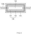
FIG. 4 is a cross-sectional view taken along line B-B ofFIG. 3 . -
FIG. 5 is a cross-sectional view illustrating a second example of a moisture absorbing material of the secondary battery according to the first embodiment of the present invention. -
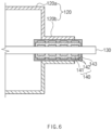
FIG. 6 is a cross-sectional view illustrating a third example of the moisture absorbing material of the secondary battery according to the first embodiment of the present invention. -
FIG. 7 is a flowchart illustrating a method for manufacturing the second battery according to the first embodiment of the present invention. -
FIGS. 8 to 12 are views illustrating the method for manufacturing the secondary battery according to the first embodiment of the present invention, whereinFIG. 8 is a perspective view illustrating a process of preparing a pouch, -
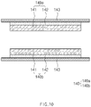
FIG. 9 is a perspective view illustrating a process of disposing an electrode assembly,FIG. 10 is a view illustrating a process of manufacturing a gas discharge part,FIG. 11 is a perspective illustrating a process of disposing the gas discharge part, andFIG. 12 is a perspective view illustrating a process of manufacturing a secondary battery to which the gas discharge part is coupled. -
FIG. 13 is a cross-sectional view of a secondary battery according to a second embodiment of the present invention. -
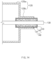
FIG. 14 is a cross-sectional view of a secondary battery according to a third embodiment of the present invention. -
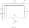
FIG. 15 is a plan view of a secondary battery according to a fourth embodiment of the present invention. -
FIG. 16 is a cross-sectional view taken along line C-C ofFIG. 15 . - Hereinafter, embodiments of the present invention will be described in detail with reference to the accompanying drawings in such a manner that the technical idea of the present invention may easily be carried out by a person with ordinary skill in the art to which the invention pertains. The present invention may, however, be embodied in different forms and should not be construed as limited to the embodiments set forth herein. In the drawings, anything unnecessary for describing the present invention will be omitted for clarity, and also like reference numerals in the drawings denote like elements.
- A
secondary battery 100 according to a first embodiment of the present invention has a structure that discharges a gas from the inside of a pouch to the outside and blocks an inflow of moisture from the outside to the inside of the pouch. - That is, as illustrated in
FIGS. 1 and2 , thesecondary battery 100 according to the first embodiment of the present invention comprises anelectrode assembly 110 to which anelectrode lead 130 is coupled, apouch 120 accommodating theelectrode assembly 110 in a state, in which a front end of theelectrode lead 130 is withdrawn to the outside, and agas discharge part 140 provided between theelectrode lead 130 and thepouch 120 to discharge a gas from the outside to the inside of thepouch 120 and block an inflow of moisture from the outside to the inside of thepouch 120. - The
electrode assembly 110 has a structure in which a plurality of electrodes are stacked in a vertical direction with a separator therebetween. Here, an electrode tab is provided on the electrode, and theelectrode lead 130 is coupled to the electrode tab. - The plurality of electrodes comprise a first electrode and a second electrode, and the electrode tab comprises a first electrode tab provided on the first electrode and a second electrode tab provided on the second electrode. The
electrode lead 130 comprises a first electrode lead coupled to the first electrode tab and a second electrode lead coupled to the second electrode tab. - Here, the first electrode may be a positive electrode, and the second electrode may be a negative electrode, and vice versa.
- The
pouch 120 comprises anaccommodation part 120a accommodating theelectrode assembly 110 and an electrolyte (not shown) in the state in which theelectrode lead 130 is withdrawn to the outside, and asealing part 120b formed along an edge of theaccommodation part 120a to seal theaccommodation part 120a. - The
pouch 120 comprises anupper case 121 and alower case 122. Theupper case 121 comprises anupper accommodation surface 121a having an accommodation groove accommodating an upper portion of theelectrode assembly 110, and anupper sealing surface 121b formed along an edge of theupper accommodation surface 121a. Thelower case 122 comprises alower accommodation surface 122a having an accommodation groove accommodating a lower portion of theelectrode assembly 110 and alower sealing surface 122b formed along an edge of thelower accommodation surface 122a. - The
pouch 120 having such a structure forms theaccommodation part 120a accommodating theentire electrode assembly 110 while theupper accommodation surface 121a and thelower accommodation surface 122a are vertically connected to each other and forms the sealingpart 120b that thermally fuses theupper sealing surface 121a and thelower sealing surface 122b to seal theaccommodation part 120a. - Here, the front end of the
electrode lead 130 is withdrawn to the outside through the sealingpart 120b disposed on one of the edges of theaccommodating part 120a That is, the front end of theelectrode lead 130 is withdrawn between theupper sealing surface 121a and thelower sealing surface 122b. - The sealing
part 120b through which theelectrode lead 130 is withdrawn has weak sealing strength when compared to the rest of the sealingpart 120b. Thus, when a gas pressure inside the pouch greatly increases, venting may occur between theelectrode lead 130 and the sealingpart 120b to cause explosion or ignition. - In order to solve the above problem, the
secondary battery 100 according to the first embodiment of the present invention may comprise thegas discharge part 140, which is provided in thepouch 120 to discharge the gas from the outside to the inside of thepouch 120 and block an inflow of moisture from the outside to the inside of thepouch 120, thereby preventing the explosion or the ignition from occurring through thegas discharge part 140. - For example, referring to
FIG. 2 , thegas discharge part 140 is provided between theelectrode lead 130 and the sealingpart 120b and comprises agas transmitting film 141 having air permeability for discharging a gas inside theaccommodation part 120a to the outside and amoisture absorbing material 142 absorbing moisture passing through thegas transmitting film 141 to block the inflow of the moisture from the outside to the inside of thepouch 120. Thus, the gas generated inside the pouch may be discharged through thegas discharge part 140 to improve safety. Particularly, thegas discharge part 140 may comprise a material that absorbs moisture to block the inflow of the moisture from the outside to the inside of thepouch 120 and discharge only the gas inside thepouch 120. - Hereinafter, the
gas discharge part 140 will be described in more detail. - As illustrated in
FIGS. 3 and4 , thegas discharge part 140 is provided between theelectrode lead 130 and the sealingpart 120b to discharge the gas from the inside to the outside of thepouch 120 and block the inflow of the moisture from the outside to the inside of thepouch 120. That is, thegas discharge part 140 has a structure capable of discharging only the gas inside the pouch to the outside. - For example, the
gas discharge part 140 comprises thegas transmitting film 141 discharging the gas from the inside to the outside of thepouch 120 and themoisture absorbing material 142 absorbing the moisture introduced into the pouch through thegas transmitting film 141. - The
gas transmitting film 141 is provided between theelectrode lead 130 and the sealingpart 120b. Preferably, thegas transmitting film 141 is provided in a shape surrounding theelectrode lead 130 between theelectrode lead 130 and the sealingpart 120b to seal a gap between theelectrode lead 130 and thegas discharge part 140. Particularly, both ends of thegas transmitting film 141 are disposed to protrude to the inside and outside of the sealingpart 120b. Thus, an area of thegas transmitting film 141 exposed to the inside and outside of thepouch 120 may increase to improve gas discharge performance and minimize a phenomenon in which thegas transmitting film 141 is blocked by foreign substances. - The
gas transmitting film 141 having such a structure may be made of a synthetic resin material having air permeability and preferably made of a thermoplastic resin. For example, the gas transmitting film may be made of polypropylene. Thus, the gas generated inside thepouch 120 may be discharged to the outside. Particularly, while thegas transmitting film 141 is provided in a shape surrounding a circumference of theelectrode lead 130 to effectively discharge the gas inside the pouch before the gap between the electrode lead and the sealing part is vented. - The
moisture absorbing material 142 is provided as a material that absorbs moisture and disposed on an outer surface of thegas transmitting film 141. Thus, themoisture absorbing material 142 is provided on thegas transmitting film 141 to absorb and remove the moisture introduced through thegas transmitting film 141 from the outside of thepouch 120. That is, themoisture absorbing material 142 blocks the inflow of the moisture from the outside to the inside of thepouch 120. - That is, the
moisture absorbing material 142 has a film shape, is provided as oxide absorbing the moisture, and is provided in a shape surrounding an outer circumference of thegas transmitting film 141. - Here, the
moisture absorbing material 142 is provided as any one of CaO, LiCl, Si3N4, SiO2, Al2O3, mullite, ZrO2, Y2O3, MgO, BeO, TiB2, TiC, HfC, and ZrC. Here, the moisture absorbing material may further comprise a getter. - The getter may be difficult to be used alone and thus may be used as a composite material comprising a binder. That is, the composite material in which the getter and the binder are combined at a set ratio may be prepared in the form of a film. The getter refers to a material that absorbs a gas or moisture remaining in a vacuum object.
- Referring to
FIG. 5 , a plurality ofmoisture absorbing materials 142, each of which has the film shape, may be disposed outside thegas transmitting film 141 at regular intervals along a longitudinal direction of theelectrode lead 130. Thus, the inflow of the moisture may be blocked in multiple stages through the plurality of moisture absorbing materials. - Referring to
FIG. 6 , themoisture absorbing material 142 having the film shape may be further disposed between theelectrode lead 130 and thegas transmitting film 141. Particularly, a plurality of electrode leads 130 may be disposed at regular intervals in the longitudinal direction between theelectrode lead 130 and thegas transmitting film 141. Thus, the moisture to be introduced between the inside and outside of thegas transmitting film 141 may be effectively absorbed and removed, and in particular, the inflow of the moisture may be blocked in multiple stages. - The
moisture absorbing material 142 may be provided to be contained inside the gas transmitting film, thereby minimizing an increase in thickness of the gas discharge part and obtain an effect of blocking the gas discharge and the moisture inflow. Particularly, themoisture absorbing material 142 may be contained to be dispersed throughout thegas transmitting film 141 or be contained in the form of a lump at a center of thegas transmitting film 141. - The
moisture absorbing material 142 may be embedded in thegas transmitting film 141 so as not to be exposed to the outside. That is, the external exposure of themoisture absorbing material 142 may be prevented to prevent the electrolyte from being contaminated by the moisture absorbing material. - An
adhesive film 143 may be provided between thegas discharge part 140 and the sealingpart 120b to improve bonding strength and sealing strength between thegas discharge part 140 and the sealingpart 120b. - The
adhesive film 143 may use any one of polypropylene (PP) and polyethylene (PE). - That is, the
adhesive film 143 is configured to bond and seal the gas transmitting film provided with the moisture absorbing material between the electrode lead and the sealing part, is made of a synthetic resin material having air permeability, and is provided in a shape surrounding a circumference of the gas transmitting film provided with the moisture absorbing material. Thus, theadhesive member 143 may seal the gap between thegas transmitting film 141 and the sealingpart 120b and discharge the gas inside the pouch to the outside together with the gas transmitting film. - Here, the
adhesive film 143 has air permeability less than that of thegas transmitting film 141. This is for discharging the gas inside the pouch together with thegas transmitting film 141 while minimizing weakening of the adhesive force of theadhesive film 143 due to the gas discharge. - The
adhesive film 143 may be provided in the shape that surrounds the entire outer circumferential surface of the gas transmitting film so that the moisture absorbing material is not exposed to the outside, thereby protecting the moisture absorbing material and preventing the electrolyte inside the pouch from being contaminated by the moisture absorbing material. - Particularly, it is possible to adjust discharging force of the gas passing through the
gas transmitting film 141 through theadhesive film 143. - Therefore, since the
secondary battery 100 according to the first embodiment of the present invention comprises thegas discharge part 140 between the electrode lead and the sealing part, the gas inside the pouch may be effectively discharged, and the inflow of the moisture from the outside to the inside of the pouch may be effectively blocked. As a result, the safety may be improved. - Hereinafter, a method for manufacturing the secondary battery according to the first embodiment of the present invention will be described.
- As illustrated in
FIGS. 7 to 12 , a method for manufacturing the secondary battery according to the first embodiment of the present invention comprises a process (a) of preparing a pouch, a process (b) of disposing an electrode assembly, a process (c) of manufacturing a gas discharge part, a process (d) of disposing the gas discharge part, and a process (e) of completing the secondary battery in which the gas discharge part is formed. - In the process (a), referring to
FIG. 8 , thepouch 120 having anupper case 121 and alower case 122 is prepared. Here, theupper case 121 comprises anupper accommodation surface 121a and anupper sealing surface 121b, and thelower case 122 comprises alower accommodation surface 122a and alower sealing surface 122b. - The
upper accommodation surface 121a and thelower accommodation surface 122a are vertically disposed to form anaccommodation part 120a accommodating the electrode assembly, and theupper sealing surface 121b and thelower sealing surface 122b are bonded to each other to form a sealingpart 120b sealing theaccommodation part 120a. - In the process (b), referring to
FIG. 9 , theupper case 121 and thelower case 122 are disposed to correspond to each other, and then, theelectrode assembly 110, to which anelectrode lead 130 is coupled, is disposed in theaccommodation part 120a formed by connecting theupper accommodation surface 121a to thelower accommodation surface 122a. - In the process (c), referring to
FIG. 10 , thegas discharge part 140 comprising agas transmitting film 141 having air permeability and amoisture absorbing material 142 that absorbs moisture is manufactured, and anadhesive film 143 having adhesive force is attached to the outside of the gas discharge part. - For example, the
gas discharge part 140 is provided with twogas discharge films gas transmitting film 141 having the air permeability and themoisture absorbing material 142 absorbing moisture are sequentially stacked, and theadhesive film 143 is attached to an outer surface of each of thegas discharge films - That is, the
gas transmitting film 141, themoisture absorbing material 142, and theadhesive film 143 have a three-layered structure. - Here, the
adhesive film 143 has an area greater than that of each of thegas transmitting film 141 and themoisture absorbing material 142, and thus, when the gas discharge part is formed, thegas transmitting film 141 and themoisture absorbing material 142 may be surrounded through theadhesive film 143. - In addition, the
moisture absorbing material 142 may have an area less than that of each of thegas transmitting film 141 and theadhesive film 143 so as to be embedded between thegas transmitting film 141 and theadhesive film 143. - The
moisture absorbing material 142 is provided as any one of CaO, LiCl, Si3N4, SiO2, Al2O3, mullite, ZrO2, Y2O3, MgO, BeO, TiB2, TiC, HfC, and ZrC, which are excellent in moisture absorption. - The
adhesive film 143 has air permeability, but has air permeability less than that of thegas transmitting film 141. - In the process (d), referring to
FIG. 11 , the gas discharge part is disposed between the upper sealing surface of the upper case and the lower sealing surface of the lower case. - More preferably, in the process (d), the
gas discharge films electrode lead 130 disposed between theupper sealing surface 121b and thelower sealing surface 122b. Here, thegas transmitting film 141 is disposed to face theelectrode lead 130. - The process (d) may further comprise a process of bonding the
gas exhaust films electrode lead 130. Here, in the process of bonding the gas exhaust films, thegas exhaust films - In the present invention, an example in which the process of bonding the
gas discharge film 140a is performed separately with respect to the process (e) will be described as an embodiment. - In the process of bonding the gas discharge film, the
gas discharge part 140 is manufactured by pressing thegas discharge film 140a disposed on the top and bottom surfaces of theelectrode lead 130. - That is, the
gas transmitting films 141 respectively disposed on the top and bottom surfaces of theelectrode lead 130 are bonded to each other to surround a circumference of theelectrode lead 130, and themoisture absorbing materials 142 respectively disposed on the top and bottom surfaces of theelectrode lead 130 may be bonded to surround a circumference of the gas transmitting film. In addition, theadhesive films 143 respectively disposed on the top and bottom surfaces of theelectrode lead 130 are bonded to seal a gap between the electrode lead and the sealing part. - Here, since the
adhesive film 143 has an area greater than that of thegas transmitting film 141, the entire gas transmitting film may be surrounded to prevent themoisture absorbing material 142 from being exposed to the outside. - In the process (e), referring to
FIG. 12 , the sealingpart 120b is formed by thermally sealing theupper sealing surface 121b and thelower sealing surface 122b. Here, thegas discharge part 140 disposed in theelectrode lead 130 together with the sealingpart 120b is also bonded to the sealingpart 120b to seal the gap between theelectrode lead 130 and the sealingpart 120b. - When the process (e) is completed as described above, the
secondary battery 100 comprising the gas discharge part as illustrated inFIG. 1 may be manufactured. - Thereafter, when a gas pressure inside the
secondary battery 100 rises, the gas inside the pouch may be discharged to the outside through the gas discharge part provided between the electrode lead and the sealing part to prevent the pouch from being vented. Here, since theadhesive film 143 also has air permeability, the gas inside the pouch may be partially discharged. Thus, it is possible to prevent the gas pressure inside the secondary battery from significantly increasing, thereby improving safety of the secondary battery. - Here, moisture from the outside of the
pouch 120 may be introduced through the gas discharge part, but may be absorbed through themoisture absorbing material 142 contained in thegas discharge part 140, and as a result, an inflow of the moisture into the pouch may be blocked. - Hereinafter, in descriptions of another embodiment of the present invention, constituents having the same function as the above-mentioned embodiment have been given the same reference numeral in the drawings, and thus duplicated description will be omitted.
- As illustrated in
FIG. 13 , asecondary battery 100 according to a second embodiment of the present invention comprises agas discharge part 140 provided between anelectrode lead 130 and a sealingpart 120b of apouch 120, and thegas discharge part 140 comprises agas transmitting film 141 and amoisture absorbing material 142. Here, anadhesive film 143 is attached to the outside of the gas discharge part. - The
adhesive film 143 comprises end surfaces 143a provided on both sides of thegas discharge part 140 exposed to the inside and outside of thepouch 120 and acircumferential surface 143b provided on a remaining surface of thegas discharge part 140. - Here, each of the end surfaces 143a has a thickness less than that of the
circumferential surface 143b to further increase in air permeability than that of thecircumferential surface 143b. That is, the thickness α of thecircumferential surface 143b is formed to be thicker than the thickness β of the end surface 143a. Thus, thecircumferential surface 143b may improve sealing force between the electrode lead and the sealing part, and the end surface 143a may adjust a discharge amount of gas discharged from the inside to the outside of the pouch while preventing the moisture absorbing material from being exposed. - As illustrated in
FIG. 14 , asecondary battery 100 according to a third embodiment of the present invention comprises agas discharge part 140. Here, thegas discharge part 140 comprises agas transmitting film 141 and amoisture absorbing material 142. Also, anadhesive film 143 is attached to the outside of thegas discharge part 140. - Here, the
moisture absorbing material 142 may be contained throughout thegas transmitting film 141. - That is, in the process (c) of manufacturing the secondary battery according to the first embodiment of the present invention, which is described above, the
moisture absorbing material 142 may be manufactured as thegas transmitting film 141 containing themoisture adsorbing material 142 while being contained when thegas transmitting film 141 is manufactured. - In more detail, a composite material may be prepared by mixing the
moisture absorbing material 142 and thegas transmitting film 141, and also, the composite material may be processed in the form of a film to manufacture thegas transmitting film 141 containing themoisture absorbing material 142. - Therefore, in the
secondary battery 100 according to the third embodiment of the present invention, the moisture passing through the gas transmitting film may be absorbed and removed through the moisture absorbing material, and the gas inside the pouch may also be discharged through the moisture absorbing material to improve the gas discharge performance. - As illustrated in
FIGS. 15 and16 , asecondary battery 100 according to a fourth embodiment of the present invention comprises anelectrode assembly 120 to which an electrode lead is coupled, apouch 120, and agas discharge part 140. Here, thegas discharge part 140 comprises agas transmitting film 141 and amoisture absorbing material 142. - Here, the
gas discharge part 140 is provided in a sealingpart 120b of thepouch 120 on which the electrode lead is not disposed. - That is, the
gas discharge part 140 is disposed between anupper sealing surface 121b and alower sealing surface 122b without the electrode lead and is coupled together when theupper sealing surface 121b and thelower sealing surface 122b are thermally fused. - An
adhesive film 143 is provided between thegas discharge part 140 and the sealingpart 120b. Here, theadhesive film 143 is attached to the outside of thegas discharge part 140. - Therefore, the
secondary battery 100 according to the fourth embodiment of the present invention may comprise the gas exhaust part even in the sealing part without the electrode lead, and as a result, the gas generated inside the secondary battery may be effectively discharged, and the inflow of moisture from the outside to the inside of the secondary battery may be blocked. - Accordingly, the scope of the present invention is defined by the appended claims more than the foregoing description and the exemplary embodiments described therein. Various modifications made within the meaning of an equivalent of the claims of the invention and within the claims are to be regarded to be in the scope of the present invention.
-
- 100:
- Secondary battery
- 110:
- Electrode assembly
- 120:
- Pouch
- 130:
- Electrode lead
- 140:
- Gas discharge part
- 141:
- Gas transmitting film
- 142:
- Moisture absorbing material
- 143:
- Adhesive film
Claims (15)
- A secondary battery comprising:an electrode assembly to which an electrode lead is coupled;a pouch comprising an accommodation part configured to accommodate the electrode assembly in a state, in which a front end of the electrode lead is withdrawn to the outside, and a sealing part formed along a circumference of the accommodation part to seal the accommodation part; anda gas discharge part provided in the pouch to discharge a gas from the inside to the outside of the pouch and block an inflow of moisture from the outside to the inside of the pouch,wherein the gas discharge part comprises: a gas transmitting film having air permeability, by which the gas inside the accommodation part is discharged to the outside; and a moisture absorbing material that absorbs the passing through the gas transmitting film to block the inflow of the moisture from the outside to the inside of the pouch.
- The secondary battery of claim 1, wherein the gas discharge part is provided between the electrode lead and the sealing part.
- The secondary battery of claim 1, wherein the gas discharge part is provided in the sealing part.
- The secondary battery of claim 2 or 3, wherein an adhesive film configured to seal a gap between the gas discharge part and the sealing part is provided between the gas discharge part and the sealing part.
- The secondary battery of claim 4, wherein the adhesive film is made of a material having air permeability.
- The secondary battery of claim 5, wherein the adhesive film is provided to surround an entire outer circumferential surface of the gas transmitting film so as not to expose the gas discharge part to the outside.
- The secondary battery of claim 5, wherein the adhesive film has air permeability less than that of the gas transmitting film.
- The secondary battery of claim 1, wherein the moisture absorbing material is provided on an outer surface of the gas transmitting film.
- The secondary battery of claim 1, wherein the moisture absorbing material is provided to be contained in the gas transmitting film.
- The secondary battery of claim 1, wherein the gas transmitting film is made of a thermoplastic resin, and
the moisture absorbing material is made of oxide that absorbs moisture. - A method for manufacturing a secondary battery, the method comprising:a process (a) of preparing a pouch provided with an upper case and a lower case, wherein the upper case is provided with an upper accommodation surface and an upper sealing surface, and the lower case is provided with a lower accommodation surface and a lower sealing surface;a process (b) of disposing an electrode assembly, to which an electrode lead is coupled, in an accommodation part formed by connecting the upper accommodation surface to the lower accommodation surface after the upper case and the lower case are disposed to correspond to each other;a process (c) of manufacturing a gas discharge part comprising a gas transmitting film having air permeability and a moisture absorbing material that absorbs moisture passing through the gas transmitting film;a process (d) of disposing the gas discharge part between the upper sealing surface of the upper case and the lower sealing surface of the lower case; anda process (e) of thermally fusing the upper sealing surface and the lower sealing surface to form a sealing part.
- The method of claim 11, wherein, in the process (d), the gas discharge part is provided between the upper sealing surface and the lower sealing surface, which correspond to the electrode lead.
- The method of claim 11, further comprising, after the gas discharge part is manufactured in the process (c), a process of attaching an adhesive film to the outside of the gas discharge part.
- The method of claim 11, wherein, in the process(c), the moisture absorbing material is provided outside the gas transmitting film.
- The method of claim 11, wherein, in the process (c), the moisture absorbing material is contained in the gas transmitting film when the gas transmitting film is manufactured.
Applications Claiming Priority (4)
| Application Number | Priority Date | Filing Date | Title |
|---|---|---|---|
| KR20200126430 | 2020-09-28 | ||
| KR20200126429 | 2020-09-28 | ||
| KR1020210125592A KR102736109B1 (en) | 2020-09-28 | 2021-09-23 | Secondary battery and manufacturing method for the same |
| PCT/KR2021/013124 WO2022065947A1 (en) | 2020-09-28 | 2021-09-27 | Secondary battery and method for manufacturing same |
Publications (3)
| Publication Number | Publication Date |
|---|---|
| EP4148886A1 true EP4148886A1 (en) | 2023-03-15 |
| EP4148886A4 EP4148886A4 (en) | 2024-07-10 |
| EP4148886B1 EP4148886B1 (en) | 2026-03-25 |
Family
ID=80846763
Family Applications (1)
| Application Number | Title | Priority Date | Filing Date |
|---|---|---|---|
| EP21872975.4A Active EP4148886B1 (en) | 2020-09-28 | 2021-09-27 | Secondary battery and method for manufacturing the same |
Country Status (5)
| Country | Link |
|---|---|
| US (1) | US20230216133A1 (en) |
| EP (1) | EP4148886B1 (en) |
| JP (1) | JP7631373B2 (en) |
| CN (1) | CN115769426A (en) |
| WO (1) | WO2022065947A1 (en) |
Families Citing this family (2)
| Publication number | Priority date | Publication date | Assignee | Title |
|---|---|---|---|---|
| CN120077509A (en) * | 2022-10-12 | 2025-05-30 | 大日本印刷株式会社 | Power storage device |
| CN120322892A (en) * | 2022-12-19 | 2025-07-15 | 株式会社 Lg新能源 | Soft pack secondary battery |
Family Cites Families (13)
| Publication number | Priority date | Publication date | Assignee | Title |
|---|---|---|---|---|
| JP3858689B2 (en) * | 2001-12-21 | 2006-12-20 | 日本電気株式会社 | BATTERY USING LAMINATE PACKAGE AND METHOD FOR MANUFACTURING THE SAME |
| JP4635415B2 (en) | 2003-07-15 | 2011-02-23 | 凸版印刷株式会社 | Sealing material for electrode tab |
| JP2006236775A (en) * | 2005-02-24 | 2006-09-07 | Nissan Motor Co Ltd | Secondary battery |
| KR100684724B1 (en) * | 2005-04-26 | 2007-02-20 | 삼성에스디아이 주식회사 | Secondary Battery and Safety Device Used in It |
| KR101182948B1 (en) * | 2006-01-09 | 2012-09-13 | 삼성에스디아이 주식회사 | Electrode Tab and Pouch Type Lithium Secondary Battery Using the Same |
| US8071231B2 (en) * | 2006-08-28 | 2011-12-06 | Lg Chem, Ltd. | Secondary battery including one-way exhaust valve |
| KR20090076364A (en) * | 2008-01-08 | 2009-07-13 | 주식회사 엘지화학 | Pouch Type Battery |
| JP2011108433A (en) * | 2009-11-16 | 2011-06-02 | Sumitomo Heavy Ind Ltd | Power storage device |
| JP2014212034A (en) * | 2013-04-18 | 2014-11-13 | 株式会社カネカ | Nonaqueous electrolyte secondary battery |
| KR20150135878A (en) * | 2014-05-26 | 2015-12-04 | 킴스테크날리지 주식회사 | Electrochemical Cell with Gas Permeable Membrane |
| JP6646352B2 (en) * | 2014-08-29 | 2020-02-14 | 住友化学株式会社 | Organic electroluminescence device |
| KR101904587B1 (en) * | 2015-09-01 | 2018-10-04 | 주식회사 엘지화학 | Battery cell and method for manufacturing the same |
| KR102555751B1 (en) * | 2017-10-17 | 2023-07-14 | 주식회사 엘지에너지솔루션 | Gas Dischargeable Pouch-Type Case for Secondary Battery |
-
2021
- 2021-09-27 US US18/009,116 patent/US20230216133A1/en active Pending
- 2021-09-27 WO PCT/KR2021/013124 patent/WO2022065947A1/en not_active Ceased
- 2021-09-27 EP EP21872975.4A patent/EP4148886B1/en active Active
- 2021-09-27 JP JP2022568643A patent/JP7631373B2/en active Active
- 2021-09-27 CN CN202180037936.XA patent/CN115769426A/en active Pending
Also Published As
| Publication number | Publication date |
|---|---|
| WO2022065947A1 (en) | 2022-03-31 |
| JP7631373B2 (en) | 2025-02-18 |
| CN115769426A (en) | 2023-03-07 |
| EP4148886A4 (en) | 2024-07-10 |
| US20230216133A1 (en) | 2023-07-06 |
| JP2023525540A (en) | 2023-06-16 |
| EP4148886B1 (en) | 2026-03-25 |
Similar Documents
| Publication | Publication Date | Title |
|---|---|---|
| KR102736109B1 (en) | Secondary battery and manufacturing method for the same | |
| US11557810B2 (en) | Battery cell having main gas discharge tube and method for manufacturing the same | |
| CN102210053B (en) | Layered secondary battery | |
| EP3637492A1 (en) | Pouch-type secondary battery sealing block for preventing cracks, pouch-type battery case manufactured by using same, and sealing method for pouch-type battery case | |
| KR101440096B1 (en) | Pouch for battery, and pouch type battery including the same | |
| KR101424003B1 (en) | Pouch-type Secondary Battery for preventing swelling phenomena | |
| EP4148886B1 (en) | Secondary battery and method for manufacturing the same | |
| EP3817082A1 (en) | Pouch case and method for manufacturing pouch-type secondary battery comprising same | |
| KR20170132565A (en) | Manufacturin method of rechargeable battery | |
| CN116250131B (en) | Battery cell and battery module including the battery cell | |
| KR102790386B1 (en) | Battery cell and battery cell manufacturing device for manufacturing the same | |
| KR20190096619A (en) | Pouch, secondary battery comprising the same, and preparation method therof | |
| EP4148846A1 (en) | Battery cell having protective member | |
| CN120657338A (en) | Battery cell and battery module comprising same | |
| KR20230173641A (en) | Battery cell and battery module including the same | |
| KR20140015201A (en) | Sealing tool for pouch case and manufacturing methode of pouch-type secondary battery | |
| US20230361399A1 (en) | Secondary battery | |
| US20230207933A1 (en) | Secondary Battery and Method for Manufacturing the Same, and Battery Pack | |
| CN108496270A (en) | secondary battery | |
| US11967734B2 (en) | Electrode assembly, secondary battery comprising the same, method for manufacturing secondary battery, and battery pack | |
| KR20160071108A (en) | Pouch type secondary battery and method of fabricating the same | |
| EP4138195B1 (en) | Secondary battery | |
| JP7592216B2 (en) | Battery cell and battery module including the battery cell | |
| EP4583264A1 (en) | Pouch-type battery case, manufacturing method therefor, and secondary battery manufacturing method | |
| US20230361396A1 (en) | Secondary battery |
Legal Events
| Date | Code | Title | Description |
|---|---|---|---|
| STAA | Information on the status of an ep patent application or granted ep patent |
Free format text: STATUS: THE INTERNATIONAL PUBLICATION HAS BEEN MADE |
|
| PUAI | Public reference made under article 153(3) epc to a published international application that has entered the european phase |
Free format text: ORIGINAL CODE: 0009012 |
|
| STAA | Information on the status of an ep patent application or granted ep patent |
Free format text: STATUS: REQUEST FOR EXAMINATION WAS MADE |
|
| 17P | Request for examination filed |
Effective date: 20221208 |
|
| AK | Designated contracting states |
Kind code of ref document: A1 Designated state(s): AL AT BE BG CH CY CZ DE DK EE ES FI FR GB GR HR HU IE IS IT LI LT LU LV MC MK MT NL NO PL PT RO RS SE SI SK SM TR |
|
| DAV | Request for validation of the european patent (deleted) | ||
| DAX | Request for extension of the european patent (deleted) | ||
| A4 | Supplementary search report drawn up and despatched |
Effective date: 20240611 |
|
| RIC1 | Information provided on ipc code assigned before grant |
Ipc: H01M 50/178 20210101ALI20240605BHEP Ipc: H01M 50/105 20210101ALI20240605BHEP Ipc: H01M 10/02 20060101ALI20240605BHEP Ipc: H01M 50/543 20210101ALI20240605BHEP Ipc: H01M 50/183 20210101ALI20240605BHEP Ipc: H01M 50/172 20210101ALI20240605BHEP Ipc: H01M 50/572 20210101ALI20240605BHEP Ipc: H01M 50/116 20210101ALI20240605BHEP Ipc: H01M 50/30 20210101AFI20240605BHEP |
|
| GRAP | Despatch of communication of intention to grant a patent |
Free format text: ORIGINAL CODE: EPIDOSNIGR1 |
|
| STAA | Information on the status of an ep patent application or granted ep patent |
Free format text: STATUS: GRANT OF PATENT IS INTENDED |
|
| INTG | Intention to grant announced |
Effective date: 20250225 |
|
| RIC1 | Information provided on ipc code assigned before grant |
Ipc: H01M 50/178 20210101ALI20250218BHEP Ipc: H01M 50/105 20210101ALI20250218BHEP Ipc: H01M 10/02 20060101ALI20250218BHEP Ipc: H01M 50/543 20210101ALI20250218BHEP Ipc: H01M 50/183 20210101ALI20250218BHEP Ipc: H01M 50/172 20210101ALI20250218BHEP Ipc: H01M 50/572 20210101ALI20250218BHEP Ipc: H01M 50/116 20210101ALI20250218BHEP Ipc: H01M 50/30 20210101AFI20250218BHEP |
|
| P01 | Opt-out of the competence of the unified patent court (upc) registered |
Free format text: CASE NUMBER: APP_13975/2025 Effective date: 20250321 |
|
| GRAJ | Information related to disapproval of communication of intention to grant by the applicant or resumption of examination proceedings by the epo deleted |
Free format text: ORIGINAL CODE: EPIDOSDIGR1 |
|
| STAA | Information on the status of an ep patent application or granted ep patent |
Free format text: STATUS: REQUEST FOR EXAMINATION WAS MADE |
|
| TPAC | Observations filed by third parties |
Free format text: ORIGINAL CODE: EPIDOSNTIPA |
|
| STAA | Information on the status of an ep patent application or granted ep patent |
Free format text: STATUS: EXAMINATION IS IN PROGRESS |
|
| INTC | Intention to grant announced (deleted) | ||
| 17Q | First examination report despatched |
Effective date: 20250602 |
|
| GRAP | Despatch of communication of intention to grant a patent |
Free format text: ORIGINAL CODE: EPIDOSNIGR1 |
|
| STAA | Information on the status of an ep patent application or granted ep patent |
Free format text: STATUS: GRANT OF PATENT IS INTENDED |
|
| INTG | Intention to grant announced |
Effective date: 20251106 |
|
| GRAS | Grant fee paid |
Free format text: ORIGINAL CODE: EPIDOSNIGR3 |
|
| GRAA | (expected) grant |
Free format text: ORIGINAL CODE: 0009210 |
|
| STAA | Information on the status of an ep patent application or granted ep patent |
Free format text: STATUS: THE PATENT HAS BEEN GRANTED |
|
| AK | Designated contracting states |
Kind code of ref document: B1 Designated state(s): AL AT BE BG CH CY CZ DE DK EE ES FI FR GB GR HR HU IE IS IT LI LT LU LV MC MK MT NL NO PL PT RO RS SE SI SK SM TR |
|
| REG | Reference to a national code |
Ref country code: CH Ref legal event code: F10 Free format text: ST27 STATUS EVENT CODE: U-0-0-F10-F00 (AS PROVIDED BY THE NATIONAL OFFICE) Effective date: 20260325 Ref country code: GB Ref legal event code: FG4D |
|
| REG | Reference to a national code |
Ref country code: DE Ref legal event code: R096 Ref document number: 602021050809 Country of ref document: DE |
|
| REG | Reference to a national code |
Ref country code: IE Ref legal event code: FG4D |