EP4148883A1 - Battery pack - Google Patents
Battery pack Download PDFInfo
- Publication number
- EP4148883A1 EP4148883A1 EP22192712.2A EP22192712A EP4148883A1 EP 4148883 A1 EP4148883 A1 EP 4148883A1 EP 22192712 A EP22192712 A EP 22192712A EP 4148883 A1 EP4148883 A1 EP 4148883A1
- Authority
- EP
- European Patent Office
- Prior art keywords
- pack
- battery
- cover
- battery cell
- present disclosure
- Prior art date
- Legal status (The legal status is an assumption and is not a legal conclusion. Google has not performed a legal analysis and makes no representation as to the accuracy of the status listed.)
- Pending
Links
Images



Classifications
-
- H—ELECTRICITY
- H01—ELECTRIC ELEMENTS
- H01M—PROCESSES OR MEANS, e.g. BATTERIES, FOR THE DIRECT CONVERSION OF CHEMICAL ENERGY INTO ELECTRICAL ENERGY
- H01M50/00—Constructional details or processes of manufacture of the non-active parts of electrochemical cells other than fuel cells, e.g. hybrid cells
- H01M50/30—Arrangements for facilitating escape of gases
- H01M50/383—Flame arresting or ignition-preventing means
-
- H—ELECTRICITY
- H01—ELECTRIC ELEMENTS
- H01M—PROCESSES OR MEANS, e.g. BATTERIES, FOR THE DIRECT CONVERSION OF CHEMICAL ENERGY INTO ELECTRICAL ENERGY
- H01M50/00—Constructional details or processes of manufacture of the non-active parts of electrochemical cells other than fuel cells, e.g. hybrid cells
- H01M50/20—Mountings; Secondary casings or frames; Racks, modules or packs; Suspension devices; Shock absorbers; Transport or carrying devices; Holders
- H01M50/204—Racks, modules or packs for multiple batteries or multiple cells
- H01M50/207—Racks, modules or packs for multiple batteries or multiple cells characterised by their shape
- H01M50/211—Racks, modules or packs for multiple batteries or multiple cells characterised by their shape adapted for pouch cells
-
- H—ELECTRICITY
- H01—ELECTRIC ELEMENTS
- H01M—PROCESSES OR MEANS, e.g. BATTERIES, FOR THE DIRECT CONVERSION OF CHEMICAL ENERGY INTO ELECTRICAL ENERGY
- H01M50/00—Constructional details or processes of manufacture of the non-active parts of electrochemical cells other than fuel cells, e.g. hybrid cells
- H01M50/20—Mountings; Secondary casings or frames; Racks, modules or packs; Suspension devices; Shock absorbers; Transport or carrying devices; Holders
- H01M50/233—Mountings; Secondary casings or frames; Racks, modules or packs; Suspension devices; Shock absorbers; Transport or carrying devices; Holders characterised by physical properties of casings or racks, e.g. dimensions
- H01M50/24—Mountings; Secondary casings or frames; Racks, modules or packs; Suspension devices; Shock absorbers; Transport or carrying devices; Holders characterised by physical properties of casings or racks, e.g. dimensions adapted for protecting batteries from their environment, e.g. from corrosion
-
- H—ELECTRICITY
- H01—ELECTRIC ELEMENTS
- H01M—PROCESSES OR MEANS, e.g. BATTERIES, FOR THE DIRECT CONVERSION OF CHEMICAL ENERGY INTO ELECTRICAL ENERGY
- H01M50/00—Constructional details or processes of manufacture of the non-active parts of electrochemical cells other than fuel cells, e.g. hybrid cells
- H01M50/20—Mountings; Secondary casings or frames; Racks, modules or packs; Suspension devices; Shock absorbers; Transport or carrying devices; Holders
- H01M50/271—Lids or covers for the racks or secondary casings
-
- H—ELECTRICITY
- H01—ELECTRIC ELEMENTS
- H01M—PROCESSES OR MEANS, e.g. BATTERIES, FOR THE DIRECT CONVERSION OF CHEMICAL ENERGY INTO ELECTRICAL ENERGY
- H01M50/00—Constructional details or processes of manufacture of the non-active parts of electrochemical cells other than fuel cells, e.g. hybrid cells
- H01M50/20—Mountings; Secondary casings or frames; Racks, modules or packs; Suspension devices; Shock absorbers; Transport or carrying devices; Holders
- H01M50/289—Mountings; Secondary casings or frames; Racks, modules or packs; Suspension devices; Shock absorbers; Transport or carrying devices; Holders characterised by spacing elements or positioning means within frames, racks or packs
-
- H—ELECTRICITY
- H01—ELECTRIC ELEMENTS
- H01M—PROCESSES OR MEANS, e.g. BATTERIES, FOR THE DIRECT CONVERSION OF CHEMICAL ENERGY INTO ELECTRICAL ENERGY
- H01M50/00—Constructional details or processes of manufacture of the non-active parts of electrochemical cells other than fuel cells, e.g. hybrid cells
- H01M50/30—Arrangements for facilitating escape of gases
-
- H—ELECTRICITY
- H01—ELECTRIC ELEMENTS
- H01M—PROCESSES OR MEANS, e.g. BATTERIES, FOR THE DIRECT CONVERSION OF CHEMICAL ENERGY INTO ELECTRICAL ENERGY
- H01M50/00—Constructional details or processes of manufacture of the non-active parts of electrochemical cells other than fuel cells, e.g. hybrid cells
- H01M50/50—Current conducting connections for cells or batteries
- H01M50/502—Interconnectors for connecting terminals of adjacent batteries; Interconnectors for connecting cells outside a battery casing
- H01M50/507—Interconnectors for connecting terminals of adjacent batteries; Interconnectors for connecting cells outside a battery casing comprising an arrangement of two or more busbars within a container structure, e.g. busbar modules
-
- H—ELECTRICITY
- H01—ELECTRIC ELEMENTS
- H01M—PROCESSES OR MEANS, e.g. BATTERIES, FOR THE DIRECT CONVERSION OF CHEMICAL ENERGY INTO ELECTRICAL ENERGY
- H01M50/00—Constructional details or processes of manufacture of the non-active parts of electrochemical cells other than fuel cells, e.g. hybrid cells
- H01M50/50—Current conducting connections for cells or batteries
- H01M50/528—Fixed electrical connections, i.e. not intended for disconnection
- H01M50/529—Intercell connections through partitions, e.g. in a battery casing
-
- H—ELECTRICITY
- H01—ELECTRIC ELEMENTS
- H01M—PROCESSES OR MEANS, e.g. BATTERIES, FOR THE DIRECT CONVERSION OF CHEMICAL ENERGY INTO ELECTRICAL ENERGY
- H01M2200/00—Safety devices for primary or secondary batteries
-
- Y—GENERAL TAGGING OF NEW TECHNOLOGICAL DEVELOPMENTS; GENERAL TAGGING OF CROSS-SECTIONAL TECHNOLOGIES SPANNING OVER SEVERAL SECTIONS OF THE IPC; TECHNICAL SUBJECTS COVERED BY FORMER USPC CROSS-REFERENCE ART COLLECTIONS [XRACs] AND DIGESTS
- Y02—TECHNOLOGIES OR APPLICATIONS FOR MITIGATION OR ADAPTATION AGAINST CLIMATE CHANGE
- Y02E—REDUCTION OF GREENHOUSE GAS [GHG] EMISSIONS, RELATED TO ENERGY GENERATION, TRANSMISSION OR DISTRIBUTION
- Y02E60/00—Enabling technologies; Technologies with a potential or indirect contribution to GHG emissions mitigation
- Y02E60/10—Energy storage using batteries
Definitions
- the present disclosure relates to a battery pack.
- a secondary battery is a battery capable of charging and discharging, and has a wide application range including relatively small portable electronic devices, mid-sized to large-sized automobiles, and power storage devices.
- the secondary battery may be used as a secondary battery cell, and the secondary battery cell may have a configuration in which a stack body including a positive electrode, a negative electrode, and a separator is disposed and an electrolyte is filled in an exterior material.
- the battery pack When the plurality of secondary battery cells in the battery pack are overcharged, exposed to heat, or exposed to various events such as receiving external shocks, or the like, the battery pack may have a risk of ignition or explosion.
- At least one of gas, flame, heat, or a conductive material may propagate to the other secondary battery cell adjacent to the one secondary battery cell.
- An aspect of the present disclosure is to improve airtightness and safety of a battery pack.
- An aspect of the present disclosure is to delay or minimize heat propagation in a battery pack.
- a battery pack includes a pack housing having a plurality of accommodation spaces; a partition member coupled to the pack housing and partitioning the plurality of accommodation spaces; a pack unit respectively disposed in the plurality of accommodation spaces; a first pack cover contacting the partition member and covering the plurality of accommodation spaces or the pack unit; and a second pack cover covering the first pack cover and the pack housing.
- the pack unit may include a plurality of battery cells, wherein at least one or more heat propagation blocking member are configured between the plurality of battery cells.
- the first pack cover may be in contact with the heat propagation blocking member to isolate the plurality of battery cells from each other in the pack unit.
- a region of the first pack cover facing the battery cell may be planar.
- a region of the first pack cover contacting the heat propagation blocking member may protrude toward the heat propagation blocking member.
- At least a portion of a region of the first pack cover, facing the battery cell may be in contact with the battery cell.
- At least a portion of the battery pack of claim 2 wherein at least a portion of an inner surface of the first pack cover, facing the battery cell, is spaced apart from the battery cell to form a venting path between the at least portion of the inner surface of the first pack cover and the battery cell.
- the heat propagation blocking member may pass through the first pack cover.
- the battery pack may further include a bus bar assembly to which electrode tab of the battery cell is connected.
- the bus bar assembly may include: a bus bar member to which the electrode tab of the battery cell is connected; and an insulating member supporting the bus bar member.
- the battery pack may further include end plates located on front and rear surfaces of the pack unit and facing the battery cell.
- an X axis is a direction, parallel to a direction perpendicular to a stacking direction of battery cells
- a Y axis is a direction, parallel to the stacking direction of the battery cells
- a Z axis is a direction, parallel to a height direction of the battery cells.
- FIG. 1 is an exploded perspective view of a battery pack according to an embodiment of the present disclosure.
- a battery pack 1000 may include a pack housing 100 having an accommodation space 111, at least one pack unit 200 accommodated in the pack housing 100, and a pack cover C covering the unit body 200 or the accommodation space 111 in which the pack unit 200 is present.
- the pack housing 100 may include at least one partition member 112, and the partition member 112 may partition the accommodation space 111.
- the partition member 112 may be provided as a single member, or a plurality of partition members 112 may be coupled to the pack housing 100, but this is not necessarily limited by the present disclosure.
- the at least one pack unit 200 may be provided in the accommodation space 111 partitioned by the partition member 112.
- the pack unit 200 may be provided as a plurality of pack units 200.
- the partition member 112 may partition the accommodation space 111 by the number corresponding to the plurality of pack units 200.
- Each of the plurality of pack units 200 may be accommodated in the accommodation space 111 partitioned into a plurality of spaces by the partition member 112.
- the number of the accommodating space 111 to be partitioned, the number of partition members 112 to be adopted, and the number of pack units 200 existing in the accommodating space 111 are not limited by the present disclosure, and may be appropriately selected and applied according to a specification of the battery pack 1000 to be required, or the like.
- the pack cover C may be coupled to at least one of the pack housing 100 and the partition member 112 to cover the accommodation space 111 or the pack unit 200.
- At least a portion of a region in which the pack cover C faces the accommodation space 111 or the pack unit 200 may protrude toward the accommodation space 111 or the pack unit 200.
- the protruding region of the pack cover C may be in contact with at least one of the pack housing 100 and the partition member 112 to isolate spaces, each in which the plurality of pack units 200 are present, for example, spaces partitioned by the partition member 112, from each other.
- Movement of a material between the pack units 200 isolated from each other may be blocked, and the material may refer collectively to a material generated when a thermal runaway phenomenon, ignition, explosion, or the like occurs in a pack unit 200 among the plurality of pack units 200, and a by-product formed by the thermal runaway phenomenon, the ignition, and the explosion, or the like.
- the partition member 112 may be provided as a hollow form, to contribute to reducing overall weight of the battery pack 1000, but this is not necessarily limited by the present disclosure.
- the pack cover C may include a first pack cover 300 and a second pack cover 400.
- the second pack cover 400 may be present on top of the first pack cover 300 in a +Z direction, and may be in contact with the first pack cover 300 .
- the second pack cover 400 may cover at least one of the first pack cover 300, the accommodation space 111, and the pack unit 200.
- the second pack cover 400 may be coupled to at least one of the pack housing 100, the partition member 112, or the first pack cover 300 by bolting, welding, bonding, or the like, but a method thereof is not necessarily limited by the present disclosure.
- the second pack cover 400 may press the first pack cover 300 in a -Z direction, and may compact the first pack cover 300 in a direction in which the pack unit 200 exists, to contribute to increasing airtightness of a space in which one pack unit 200 is disposed.
- the second pack cover 400 may press the first pack cover 300, a separate component for fastening the first pack cover 300 to the pack housing 100 may not be required. This may contribute to simplifying a structure of the battery pack 1000.
- a first pack cover 300 may cover the pack unit 200 or the accommodation space 111 from the bottom of the second pack cover 400 in the -Z direction.
- the first pack cover 300 may be provided as a plurality of first pack covers 300, and the number of first pack covers 300 corresponding to the number of the pack units 200 may be provided.
- the first pack cover 300 and the pack unit 200 may correspond in a one-to-one relationship, and each of the plurality of pack units 200 may be covered by each of the plurality of first pack covers 300.
- the first pack cover 300 may be present on the top of the plurality of pack units 200 in the +Z direction, and may cover an upper portion of each of the pack units 200, to isolate or seal a space allocated to one pack unit 200.
- airtightness of the accommodation space 111 in which one pack unit 200 is present may be improved.
- a thermal runaway phenomenon, ignition, explosion, or the like occurs in the one pack unit 200, transferring of the thermal runaway phenomenon, the ignition, the explosion, or the like to the other pack unit 200, or propagation of a material generated by these may be delayed, minimized, or prevented.
- the material generated by the thermal runaway phenomenon, the ignition, the explosion, or the like may be, for example, at least one of flame, gas, or a particle.
- the gas may be at least any one or more of a gas generated by an electrolyte, or a combustion gas, and the particle may be at least one of combustion material particles, or a particle of an element constituting the battery pack 1000.
- the second pack cover 400 may be disposed on the top of the pack unit 200 to delay, minimize, or prevent propagation of the gas from the pack unit 200, in which the gas is initially generated, to the other pack unit 200.
- the partition member 112 may include a first venting hole 112a, which may be a through-hole in a region facing the pack unit 200, and may include a first hollow portion 112b, which may be a hollow portion therein. At least one of gas or combustion gas by the electrolyte, generated in the pack unit 200 may be introduced into the first venting hole 112a.
- the first hollow portion 112b may be present in the partition member 112 in at least one direction of a direction parallel to the X-axis, or a direction parallel to the Y-axis.
- the first hollow portion 112b existing in a direction parallel to the Y-axis may be connected to the first venting hole 112a and a second hollow portion 110 formed in the pack housing 100.
- the second hollow portion 110 may be present in the pack housing 100 in at least one direction of a direction parallel to the X-axis, or a direction parallel to the Y-axis.
- the second hollow portion 110 existing in a direction parallel to the X-axis may be connected to the first hollow portion 112b existing in a direction parallel to the Y-axis of the partition member 112, as described above.
- the second hollow portion 110 existing in a direction parallel to the Y-axis may be connected to the first hollow portion 112b of the partition member 112 existing in a direction parallel to the X-axis.
- the first hollow portion 112b and the second hollow portion 110 may be continuously present to have a predetermined section in the pack housing 100, and the second hollow portion 110 may be provided in communication with an outside of the pack housing 100.
- the pack housing 100 may include a second venting hole 110a in a region facing the partition member 112.
- the second venting hole 110a may serve to connect the second hollow portion 110 existing in a direction parallel to the X-axis of the pack housing 100 and the first hollow portion 112b existing in a direction parallel to the Y-axis of the partition member 112, and may serve to connect the second hollow portion 110 existing in a direction parallel to the Y axis of the pack housing 100 and the first hollow portion 112b existing in a direction parallel to the X axis of the partition member 112.
- At least one of gas or combustion gas generated by the electrolyte generated in the pack unit 200 may flow into the first venting hole 112a and may pass through the first hollow portion 112b and the second hollow portion 110, to be discharged to the outside of the pack housing 100.
- the first hollow portion 112b and the second hollow portion 110 not only create an effect of forming an exhaust path of at least one of gas or combustion gas by the electrolyte generated in the pack unit 200, but also contribute to reducing a weight of the battery pack 1000.
- FIG. 2 is a partially exploded perspective view of a pack unit 200 according to an embodiment of the present disclosure.
- the pack unit 200 may include a plurality of cell groups 210 formed by including a plurality of battery cells 211, and at least one heat propagation blocking member 220 disposed between the battery cells 211 or the cell groups 210.
- the battery cells 211 may be stacked in a +Y direction or a -Y direction to form one cell group 210.
- the number of battery cells 211 stacked to form the one cell group 210 is not necessarily limited by the present disclosure, and may be appropriately selected and applied according to a specification of a battery pack to be required.
- the cell group 210 may be stacked in the +Y direction or the -Y direction. At least one of a buffer pad (not illustrated) disposed between the battery cells 211 to correspond to expansion of the battery cells 211, or a cooling pad (not illustrated) disposed between the battery cells 211 to cool the battery cells 211, may be disposed in the cell group 210, but this is not necessarily limited by the present disclosure.
- the heat propagation blocking member 220 may be disposed between the plurality of battery cells 211 constituting the cell group 210 or between the plurality of cell groups 210, or both thereof.
- the plurality of cell groups 210 with the heat propagation blocking member 220 interposed therebetween may be isolated from each other.
- the heat propagation blocking member 220 may serve to delay, minimize, or prevent propagation of a thermal runaway phenomenon, ignition, explosion, or the like occurring in one cell group 210 to an adjacent cell group 210, and may serve to delay, minimize, or prevent propagation of damage due to the thermal runaway phenomenon, the ignition, the explosion, or the like to a cell group 210 in which no thermal runaway phenomenon, ignition, explosion, or the like has occurred.
- the plurality of cell groups 210 and the plurality of heat propagation blocking member 220, stacked in +Y direction or the -Y direction, may be supported by at least one of an end plate 201 or a bus bar assembly 202.
- the bus bar assembly 202 may include a bus bar member 203 electrically connected to an electrode tab 211a of the battery cell 211, and an insulating member 204 supporting the bus bar member 203.
- the bus bar member 203 may include a slot 203a to which the electrode tab 211a is connected.
- the slot 203a may be a passage through which at least one of gas or combustion gas by an electrolyte generated in the battery cell 211 is discharged. In an embodiment of the present disclosure, at least any one of gas and combustion gas by the electrolyte leaked into the slot 203a may be introduced into a venting hole (112a in FIG. 1 ) provided in a partition member (112 in FIG. 1 ).
- the battery cells 211 located on a front surface and a rear surface of the pack unit 200, may face the end plate 201, and the end plate 201 may be disposed in a region in which the bus bar assembly 202 does not exist.
- the end plate 201 may be coupled to the bus bar assembly 202, but this is also not necessarily limited by the present disclosure, which may be appropriately selected and applied according to a specification of a battery pack to be required.
- the pack unit 200 when configured by at least one of the bus bar assembly 202 or the end plate 201, the pack unit 200 may be completed without using a separate member. Therefore, there may be an advantage of reducing light an overall weight of a battery pack.
- the end plate 201 and the bus bar assembly 202 may support the pack unit 200 to expose upper and lower portions of the pack unit 200 in the Z-axis direction.
- the pack unit 200 of which lower portion is exposed by at least one of the end plate 201 or the bus bar assembly 202 may be directly seated on a bottom surface of a pack housing (100 in FIG. 1 ) .
- a pack unit 200 When a pack unit 200 is supported by at least any one of the end plate 201 or the bus bar assembly 202, a plurality of battery cells 211 may be formed as the pack unit 200, even without a case (not illustrated) covering a bottom of the pack unit 200.
- the pack unit 200 formed in this manner may be directly seated on the bottom surface of the pack housing (100 in FIG. 1 ), a weight of a battery pack may be reduced, or a size of the battery cells 211 may be increased to increase capacity of the battery pack.
- a resin (not illustrated) or the like may be applied between the bottom of the pack unit 200 and the pack housing (100 in FIG. 1 ), but this is not necessarily limited by the present disclosure.
- FIG. 3 is a cross-sectional view of FIG. 1 , taken along line A-A'. To increase visibility of the drawing, a cross-sectional view of the battery cell 211 is not illustrated in FIG. 3 .
- the partition member 112 may be provided integrally in the pack housing 100, and may protrude from the pack housing 100 to be disposed between the pack units 200.
- An uppermost portion of the partition member 112 in the +Z direction may be present on a higher level, as compared to an uppermost portion of a battery cell 211, an uppermost portion of a heat propagation blocking member 220, and an uppermost portion of the first pack cover 300 in the +Z direction.
- One pack unit 200 may be formed by stacking a plurality of cell groups 210 in the +Y direction or the -Y direction, and disposing the heat propagation blocking member 220 between the cell groups 210.
- An upper portion of the one pack unit 200 in the +Z direction may be primarily covered by the first pack cover 300, and may be secondarily covered by the second pack cover 400 present on the top of the first pack cover 300 in the +Z direction.
- the second pack cover 400 may cover at least a portion of the plurality of pack units 200, at least a portion of the accommodation space (111 in FIG. 1 ), at least a portion of the partition member 112, and at least a portion of the pack housing 100.
- An inner surface of the second pack cover 400 facing the pack unit 200 may be in contact with the pack housing 100, the first pack cover 300, and the partition member 112, and the second pack cover 400 may press the first pack cover 300 by a weight of the second pack cover 400.
- FIG. 4 is a view in which a portion of FIG. 3 is enlarged and disassembled.
- a height H1 of the pack housing 100 may be longer than a height H2 of the battery cell 211, in a height direction.
- the height direction may be a direction, intersecting a direction in which the battery cells 211 are stacked.
- a level of an uppermost portion of the pack housing 100 in the +Z direction may be higher than a level of an uppermost portion of the battery cell 211 in the +Z direction. Therefore, the uppermost portion of the pack housing 100 in the +Z direction may be present on a higher level than the uppermost portion of the battery cell 211 in the +Z direction.
- the pack unit 200 may be easily accommodated in the pack housing 100, and a space in which one pack unit 200 is present may be easily isolated from other spaces in the pack housing 100.
- FIG. 5 is a partially enlarged view of FIG. 3 .
- one heat propagation blocking member 220 may be disposed between a cell group 210a existing in an outermost portion of the pack unit 200 and contacting the end plate 201, and a cell group 210b adjacent to the cell group 210a.
- the other heat propagation blocking member 220 may be disposed between the cell group 210b and a cell group 210c adjacent to the cell group 210b.
- a heat propagation blocking member 220 may be disposed for a cell group 210 in a pack unit 200, in the same manner as described above, and the heat propagation blocking member 220 may be in contact with the cell group 210, respectively, to isolate the cell groups 210 from each other in the pack unit 200.
- a surface of the first pack cover 300 facing the battery cell 211 may be in contact with the battery cell 211, and a surface of the first pack cover 300 facing the heat propagation blocking member 220 may be in contact with the heat propagation blocking member 220.
- a height level of the heat propagation blocking member 220 may be lower than a height level of the battery cell 211.
- a surface of the first pack cover 300 facing the battery cell 211 may be provided as a planar surface in the Y-axis direction, and the planar surface may be a planar portion 301.
- a surface of the first pack cover 300 facing the heat propagation blocking member 220 may be connected to the planar portion 301 and may protrude in a direction facing the heat propagation blocking member 220, to become a protruding portion 302.
- a cross-sectional shape of the first pack cover 300 may be such that the planar portion 301 and the protruding portion 302 are alternately arranged in the Y-axis direction, and the planar portion 301 and the protruding portion 302 may form a concave-convex portion in the cross-sectional shape of the first pack cover 300.
- a height H3 of the planar portion 301, the surface of the first pack cover 300 facing the battery cell 211, may be, at least, equal to the height H2 of the battery cell 211.
- gas generated from the pack unit 200 may be guided to a separate external venting path(not illustrated) provided in the pack housing 100, to be discharged to an outside of the pack housing 100, or may be discharged through a slot (203a in FIG. 2 ) formed in the bus bar member (203 in FIG. 1 ) to pass through a first venting hole (112a in FIG. 1 ), a first hollow portion (112b in FIG. 1 ), a second venting hole (110a in FIG. 1 ), and a second hollow portion (110 in FIG. 1 ), to be discharged to the outside of the pack housing 100. Since explanations related to venting do not fall within the main characteristics of the present disclosure, a detailed description thereof will be omitted.
- FIG. 6 is a partially enlarged view of a portion corresponding to FIG. 3 , according to another embodiment of the present disclosure.
- a first pack cover 300 may include a concave-convex portion in the cross-sectional shape of a region of the first pack cover 300 facing a pack unit 200.
- An embodiment illustrated in FIG. 6 may be different from the embodiment illustrated in FIG. 5 in view that the first pack cover 300 has an irregular surface to include a third hollow portion 303.
- the third hollow portion 303 may be formed on a surface of the first pack cover 300, opposite to a surface of which the first pack cover 300 faces the pack unit 200.
- the third hollow portion 303 may be formed in a region in which the first pack cover 300 protrudes toward the heat propagation blocking member 220.
- the third hollow portion 303 may be provided as a plurality of third hollow portions 303 on the first pack cover 300, and the plurality of third hollow portions 303 may be spaced apart from each other on the first pack cover 300 by a predetermined distance in the Y-axis direction.
- the third hollow portion 303 may be continuous in the X-axis (X in FIG. 1 ) direction, and an upper portion of the third hollow portion 303 may be sealed by being covered by a second pack cover 400.
- the third hollow portion 303 may be used as a flow path through which a refrigerant flows or as a flow path for venting, but this is not necessarily limited by the present disclosure, and may be appropriately selected and applied according to a specification of a battery pack to be required.
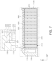
- FIG. 7 is a partially enlarged view of a portion corresponding to FIG. 3 , according to another embodiment of the present disclosure.
- an inner surface of a first pack cover 300 facing a pack unit 200 may be spaced apart from a battery cell 211 or a cell group 210, to form a venting path 310 between the first pack cover 300 and the cell group 210.
- the first pack cover 300 may also be in contact with a heat propagation blocking member 220 to form a plurality of venting path 310.
- Each of the venting path 310 may exist on a plurality of cell groups 210.
- the venting path 310 may be connected to at least one of a separate external venting path (not illustrated) and a first venting hole (112a in FIG. 1 ), formed in a pack housing 100.
- FIG. 8 is a partially enlarged view of a portion corresponding to FIG. 3 , according to another embodiment of the present disclosure.
- a heat propagation blocking member 220 may pass through a first pack cover 300, and an end portion 221 of the heat propagation blocking member 220 may exist in a third hollow portion 303.
- a through-hole (not illustrated) formed on the first pack cover 300 and through which the heat propagation blocking member 220 passes, and an outer periphery of the heat propagation blocking member 220 may be formed to have tolerance in intermediate fitting or loosely fitting.
- airtightness of a battery pack may be improved, and heat propagation in the battery pack may be delayed or minimized.
- safety of a battery pack may be improved.
Landscapes
- Chemical & Material Sciences (AREA)
- Chemical Kinetics & Catalysis (AREA)
- Electrochemistry (AREA)
- General Chemical & Material Sciences (AREA)
- Battery Mounting, Suspending (AREA)
- Secondary Cells (AREA)
Abstract
Description
- The present disclosure relates to a battery pack.
- A secondary battery is a battery capable of charging and discharging, and has a wide application range including relatively small portable electronic devices, mid-sized to large-sized automobiles, and power storage devices.
- The secondary battery may be used as a secondary battery cell, and the secondary battery cell may have a configuration in which a stack body including a positive electrode, a negative electrode, and a separator is disposed and an electrolyte is filled in an exterior material.
- When a plurality of secondary battery cells are electrically connected to form a battery pack, capacity and an output amount of the battery pack may increase.
- When the plurality of secondary battery cells in the battery pack are overcharged, exposed to heat, or exposed to various events such as receiving external shocks, or the like, the battery pack may have a risk of ignition or explosion.
- In particular, when ignition or explosions occur in one secondary battery cell of the secondary battery cells constituting the battery pack, at least one of gas, flame, heat, or a conductive material may propagate to the other secondary battery cell adjacent to the one secondary battery cell.
- Therefore, in order to prevent ignition or explosion of a battery pack, it may be very important to minimize or prevent propagation of at least one of gas, flame, heat, or a conductive material from one secondary battery cell in which the ignition or explosion is first started to the other secondary battery cell.
- An aspect of the present disclosure is to improve airtightness and safety of a battery pack.
- An aspect of the present disclosure is to delay or minimize heat propagation in a battery pack.
- According to an aspect of the present disclosure, a battery pack includes a pack housing having a plurality of accommodation spaces; a partition member coupled to the pack housing and partitioning the plurality of accommodation spaces; a pack unit respectively disposed in the plurality of accommodation spaces; a first pack cover contacting the partition member and covering the plurality of accommodation spaces or the pack unit; and a second pack cover covering the first pack cover and the pack housing.
- In an embodiment, the pack unit may include a plurality of battery cells, wherein at least one or more heat propagation blocking member are configured between the plurality of battery cells.
- Also, in an embodiment, the first pack cover may be in contact with the heat propagation blocking member to isolate the plurality of battery cells from each other in the pack unit.
- Also, in an embodiment, a region of the first pack cover facing the battery cell may be planar.
- Also, in an embodiment, a region of the first pack cover contacting the heat propagation blocking member may protrude toward the heat propagation blocking member.
- Also, in an embodiment, at least a portion of a region of the first pack cover, facing the battery cell, may be in contact with the battery cell.
- Also, in an embodiment, at least a portion of the battery pack of claim 2, wherein at least a portion of an inner surface of the first pack cover, facing the battery cell, is spaced apart from the battery cell to form a venting path between the at least portion of the inner surface of the first pack cover and the battery cell.
- In addition, in an embodiment, the heat propagation blocking member may pass through the first pack cover.
- Also, in an embodiment, the battery pack may further include a bus bar assembly to which electrode tab of the battery cell is connected.
- In one embodiment, the bus bar assembly may include: a bus bar member to which the electrode tab of the battery cell is connected; and an insulating member supporting the bus bar member.
- Also, in an embodiment, the battery pack may further include end plates located on front and rear surfaces of the pack unit and facing the battery cell.
- The above and other aspects, features, and advantages of the present disclosure will be more clearly understood from the following detailed description, taken in conjunction with the accompanying drawings, in which:
-
FIG. 1 is an exploded perspective view of a battery pack according to an embodiment of the present disclosure. -
FIG. 2 is a partially exploded perspective view of a pack unit according to an embodiment of the present disclosure. -
FIG. 3 is a cross-sectional view ofFIG. 1 , taken along line A-A'. -
FIG. 4 is a view in which a portion ofFIG. 3 is enlarged and disassembled. -
FIG. 5 is a partially enlarged view ofFIG. 3 . -
FIG. 6 is a partially enlarged view of a portion corresponding toFIG. 3 , according to another embodiment of the present disclosure. -
FIG. 7 is a partially enlarged view of a portion corresponding toFIG. 3 , according to another embodiment of the present disclosure. -
FIG. 8 is a partially enlarged view of a portion corresponding toFIG. 3 , according to another embodiment of the present disclosure. - In order to help understanding of a description of embodiments of the present disclosure, elements indicated with the same reference numerals in the accompanying drawings are the same elements, and related elements among the elements that perform the same action in each embodiment are marked with the same numeral or related numerals.
- In addition, in order to clarify a gist of the present disclosure, a description of elements and techniques well known in the prior art will be omitted, and hereinafter, the present disclosure will be described in detail with reference to the accompanying drawings.
- However, it can be understood that the spirit of the present disclosure is not limited to embodiments to be provided, and specific components may be proposed in other forms in which specific elements are added, changed, or deleted by those skilled in the art, but this is also included within the scope of the same spirit as the present disclosure.
- Hereinafter, as illustrated in the accompanying drawings, an X axis is a direction, parallel to a direction perpendicular to a stacking direction of battery cells, a Y axis is a direction, parallel to the stacking direction of the battery cells, and a Z axis is a direction, parallel to a height direction of the battery cells.
-
FIG. 1 is an exploded perspective view of a battery pack according to an embodiment of the present disclosure. - As illustrated in
FIG. 1 , abattery pack 1000 according to an embodiment of the present disclosure may include apack housing 100 having anaccommodation space 111, at least onepack unit 200 accommodated in thepack housing 100, and a pack cover C covering theunit body 200 or theaccommodation space 111 in which thepack unit 200 is present. - The
pack housing 100 may include at least onepartition member 112, and thepartition member 112 may partition theaccommodation space 111. Thepartition member 112 may be provided as a single member, or a plurality ofpartition members 112 may be coupled to thepack housing 100, but this is not necessarily limited by the present disclosure. - The at least one
pack unit 200 may be provided in theaccommodation space 111 partitioned by thepartition member 112. - In an embodiment of the present disclosure, the
pack unit 200 may be provided as a plurality ofpack units 200. In addition, thepartition member 112 may partition theaccommodation space 111 by the number corresponding to the plurality ofpack units 200. - Each of the plurality of
pack units 200 may be accommodated in theaccommodation space 111 partitioned into a plurality of spaces by thepartition member 112. - The number of the
accommodating space 111 to be partitioned, the number ofpartition members 112 to be adopted, and the number ofpack units 200 existing in theaccommodating space 111 are not limited by the present disclosure, and may be appropriately selected and applied according to a specification of thebattery pack 1000 to be required, or the like. - The pack cover C may be coupled to at least one of the
pack housing 100 and thepartition member 112 to cover theaccommodation space 111 or thepack unit 200. - At least a portion of a region in which the pack cover C faces the
accommodation space 111 or thepack unit 200 may protrude toward theaccommodation space 111 or thepack unit 200. The protruding region of the pack cover C may be in contact with at least one of thepack housing 100 and thepartition member 112 to isolate spaces, each in which the plurality ofpack units 200 are present, for example, spaces partitioned by thepartition member 112, from each other. - Movement of a material between the
pack units 200 isolated from each other may be blocked, and the material may refer collectively to a material generated when a thermal runaway phenomenon, ignition, explosion, or the like occurs in apack unit 200 among the plurality ofpack units 200, and a by-product formed by the thermal runaway phenomenon, the ignition, and the explosion, or the like. - In addition, the
partition member 112 may be provided as a hollow form, to contribute to reducing overall weight of thebattery pack 1000, but this is not necessarily limited by the present disclosure. - In an embodiment of the present disclosure, the pack cover C may include a
first pack cover 300 and asecond pack cover 400. Thesecond pack cover 400 may be present on top of thefirst pack cover 300 in a +Z direction, and may be in contact with thefirst pack cover 300 . In addition, thesecond pack cover 400 may cover at least one of thefirst pack cover 300, theaccommodation space 111, and thepack unit 200. - The
second pack cover 400 may be coupled to at least one of thepack housing 100, thepartition member 112, or thefirst pack cover 300 by bolting, welding, bonding, or the like, but a method thereof is not necessarily limited by the present disclosure. - The
second pack cover 400 may press thefirst pack cover 300 in a -Z direction, and may compact thefirst pack cover 300 in a direction in which thepack unit 200 exists, to contribute to increasing airtightness of a space in which onepack unit 200 is disposed. - In addition, since the
second pack cover 400 may press thefirst pack cover 300, a separate component for fastening thefirst pack cover 300 to thepack housing 100 may not be required. This may contribute to simplifying a structure of thebattery pack 1000. - A
first pack cover 300 according to an embodiment of the present disclosure may cover thepack unit 200 or theaccommodation space 111 from the bottom of thesecond pack cover 400 in the -Z direction. - The
first pack cover 300 may be provided as a plurality of first pack covers 300, and the number of first pack covers 300 corresponding to the number of thepack units 200 may be provided. Thefirst pack cover 300 and thepack unit 200 may correspond in a one-to-one relationship, and each of the plurality ofpack units 200 may be covered by each of the plurality of first pack covers 300. - The
first pack cover 300 may be present on the top of the plurality ofpack units 200 in the +Z direction, and may cover an upper portion of each of thepack units 200, to isolate or seal a space allocated to onepack unit 200. - Therefore, airtightness of the
accommodation space 111 in which onepack unit 200 is present may be improved. In addition, when a thermal runaway phenomenon, ignition, explosion, or the like occurs in the onepack unit 200, transferring of the thermal runaway phenomenon, the ignition, the explosion, or the like to theother pack unit 200, or propagation of a material generated by these may be delayed, minimized, or prevented. - The material generated by the thermal runaway phenomenon, the ignition, the explosion, or the like may be, for example, at least one of flame, gas, or a particle. The gas may be at least any one or more of a gas generated by an electrolyte, or a combustion gas, and the particle may be at least one of combustion material particles, or a particle of an element constituting the
battery pack 1000. - When the material generated by the thermal runaway phenomenon, the ignition, the explosion, or the like is gas, because the gas may be highly likely to propagate through a path existing the top of the
pack unit 200 in the +Z direction due to nature of the gas, by thesecond pack cover 400 may be disposed on the top of thepack unit 200 to delay, minimize, or prevent propagation of the gas from thepack unit 200, in which the gas is initially generated, to theother pack unit 200. - In an embodiment of the present disclosure, the
partition member 112 may include afirst venting hole 112a, which may be a through-hole in a region facing thepack unit 200, and may include a firsthollow portion 112b, which may be a hollow portion therein. At least one of gas or combustion gas by the electrolyte, generated in thepack unit 200 may be introduced into thefirst venting hole 112a. - The first
hollow portion 112b may be present in thepartition member 112 in at least one direction of a direction parallel to the X-axis, or a direction parallel to the Y-axis. In an embodiment of the present disclosure, the firsthollow portion 112b existing in a direction parallel to the Y-axis may be connected to thefirst venting hole 112a and a secondhollow portion 110 formed in thepack housing 100. - The second
hollow portion 110 may be present in thepack housing 100 in at least one direction of a direction parallel to the X-axis, or a direction parallel to the Y-axis. The secondhollow portion 110 existing in a direction parallel to the X-axis may be connected to the firsthollow portion 112b existing in a direction parallel to the Y-axis of thepartition member 112, as described above. The secondhollow portion 110 existing in a direction parallel to the Y-axis may be connected to the firsthollow portion 112b of thepartition member 112 existing in a direction parallel to the X-axis. - The first
hollow portion 112b and the secondhollow portion 110 may be continuously present to have a predetermined section in thepack housing 100, and the secondhollow portion 110 may be provided in communication with an outside of thepack housing 100. In addition, thepack housing 100 may include asecond venting hole 110a in a region facing thepartition member 112. Thesecond venting hole 110a may serve to connect the secondhollow portion 110 existing in a direction parallel to the X-axis of thepack housing 100 and the firsthollow portion 112b existing in a direction parallel to the Y-axis of thepartition member 112, and may serve to connect the secondhollow portion 110 existing in a direction parallel to the Y axis of thepack housing 100 and the firsthollow portion 112b existing in a direction parallel to the X axis of thepartition member 112. - Therefore, at least one of gas or combustion gas generated by the electrolyte generated in the
pack unit 200 may flow into thefirst venting hole 112a and may pass through the firsthollow portion 112b and the secondhollow portion 110, to be discharged to the outside of thepack housing 100. The firsthollow portion 112b and the secondhollow portion 110 not only create an effect of forming an exhaust path of at least one of gas or combustion gas by the electrolyte generated in thepack unit 200, but also contribute to reducing a weight of thebattery pack 1000. -
FIG. 2 is a partially exploded perspective view of apack unit 200 according to an embodiment of the present disclosure. - As illustrated in
FIG. 2 , thepack unit 200 may include a plurality ofcell groups 210 formed by including a plurality ofbattery cells 211, and at least one heatpropagation blocking member 220 disposed between thebattery cells 211 or thecell groups 210. - The
battery cells 211 may be stacked in a +Y direction or a -Y direction to form onecell group 210. - The number of
battery cells 211 stacked to form the onecell group 210 is not necessarily limited by the present disclosure, and may be appropriately selected and applied according to a specification of a battery pack to be required. - The
cell group 210 may be stacked in the +Y direction or the -Y direction. At least one of a buffer pad (not illustrated) disposed between thebattery cells 211 to correspond to expansion of thebattery cells 211, or a cooling pad (not illustrated) disposed between thebattery cells 211 to cool thebattery cells 211, may be disposed in thecell group 210, but this is not necessarily limited by the present disclosure. - The heat
propagation blocking member 220 may be disposed between the plurality ofbattery cells 211 constituting thecell group 210 or between the plurality ofcell groups 210, or both thereof. The plurality ofcell groups 210 with the heatpropagation blocking member 220 interposed therebetween may be isolated from each other. - The heat
propagation blocking member 220 may serve to delay, minimize, or prevent propagation of a thermal runaway phenomenon, ignition, explosion, or the like occurring in onecell group 210 to anadjacent cell group 210, and may serve to delay, minimize, or prevent propagation of damage due to the thermal runaway phenomenon, the ignition, the explosion, or the like to acell group 210 in which no thermal runaway phenomenon, ignition, explosion, or the like has occurred. - The plurality of
cell groups 210 and the plurality of heatpropagation blocking member 220, stacked in +Y direction or the -Y direction, may be supported by at least one of anend plate 201 or abus bar assembly 202. - The
bus bar assembly 202 may include abus bar member 203 electrically connected to anelectrode tab 211a of thebattery cell 211, and an insulatingmember 204 supporting thebus bar member 203. Thebus bar member 203 may include aslot 203a to which theelectrode tab 211a is connected. Theslot 203a may be a passage through which at least one of gas or combustion gas by an electrolyte generated in thebattery cell 211 is discharged. In an embodiment of the present disclosure, at least any one of gas and combustion gas by the electrolyte leaked into theslot 203a may be introduced into a venting hole (112a inFIG. 1 ) provided in a partition member (112 inFIG. 1 ). - The
battery cells 211, located on a front surface and a rear surface of thepack unit 200, may face theend plate 201, and theend plate 201 may be disposed in a region in which thebus bar assembly 202 does not exist. In an embodiment of the present disclosure, theend plate 201 may be coupled to thebus bar assembly 202, but this is also not necessarily limited by the present disclosure, which may be appropriately selected and applied according to a specification of a battery pack to be required. - In this manner, when the
pack unit 200 is configured by at least one of thebus bar assembly 202 or theend plate 201, thepack unit 200 may be completed without using a separate member. Therefore, there may be an advantage of reducing light an overall weight of a battery pack. - In an embodiment of the present disclosure, the
end plate 201 and thebus bar assembly 202 may support thepack unit 200 to expose upper and lower portions of thepack unit 200 in the Z-axis direction. - The
pack unit 200 of which lower portion is exposed by at least one of theend plate 201 or thebus bar assembly 202 may be directly seated on a bottom surface of a pack housing (100 inFIG. 1 ) . When apack unit 200 is supported by at least any one of theend plate 201 or thebus bar assembly 202, a plurality ofbattery cells 211 may be formed as thepack unit 200, even without a case (not illustrated) covering a bottom of thepack unit 200. In addition, since thepack unit 200 formed in this manner may be directly seated on the bottom surface of the pack housing (100 inFIG. 1 ), a weight of a battery pack may be reduced, or a size of thebattery cells 211 may be increased to increase capacity of the battery pack. - A resin (not illustrated) or the like may be applied between the bottom of the
pack unit 200 and the pack housing (100 inFIG. 1 ), but this is not necessarily limited by the present disclosure. -
FIG. 3 is a cross-sectional view ofFIG. 1 , taken along line A-A'. To increase visibility of the drawing, a cross-sectional view of thebattery cell 211 is not illustrated inFIG. 3 . - As illustrated in
FIG. 3 , in an embodiment of the present disclosure, thepartition member 112 may be provided integrally in thepack housing 100, and may protrude from thepack housing 100 to be disposed between thepack units 200. An uppermost portion of thepartition member 112 in the +Z direction may be present on a higher level, as compared to an uppermost portion of abattery cell 211, an uppermost portion of a heatpropagation blocking member 220, and an uppermost portion of thefirst pack cover 300 in the +Z direction. - According to this, it is possible to easily isolate or seal each of the
pack units 200 in thepack housing 100 only by designing a height of thepack housing 100, a height of thepartition member 112, and a height of thepack unit 200, without a separate configuration. - One
pack unit 200 according to an embodiment of the present disclosure may be formed by stacking a plurality ofcell groups 210 in the +Y direction or the -Y direction, and disposing the heatpropagation blocking member 220 between thecell groups 210. - An upper portion of the one
pack unit 200 in the +Z direction may be primarily covered by thefirst pack cover 300, and may be secondarily covered by thesecond pack cover 400 present on the top of thefirst pack cover 300 in the +Z direction. - The
second pack cover 400 may cover at least a portion of the plurality ofpack units 200, at least a portion of the accommodation space (111 inFIG. 1 ), at least a portion of thepartition member 112, and at least a portion of thepack housing 100. An inner surface of thesecond pack cover 400 facing thepack unit 200 may be in contact with thepack housing 100, thefirst pack cover 300, and thepartition member 112, and thesecond pack cover 400 may press thefirst pack cover 300 by a weight of thesecond pack cover 400. -
FIG. 4 is a view in which a portion ofFIG. 3 is enlarged and disassembled. - As illustrated in
FIG. 4 , in an embodiment of the present disclosure, a height H1 of thepack housing 100 may be longer than a height H2 of thebattery cell 211, in a height direction. In this case, the height direction may be a direction, intersecting a direction in which thebattery cells 211 are stacked. - In addition, a level of an uppermost portion of the
pack housing 100 in the +Z direction may be higher than a level of an uppermost portion of thebattery cell 211 in the +Z direction. Therefore, the uppermost portion of thepack housing 100 in the +Z direction may be present on a higher level than the uppermost portion of thebattery cell 211 in the +Z direction. - Therefore, the
pack unit 200 may be easily accommodated in thepack housing 100, and a space in which onepack unit 200 is present may be easily isolated from other spaces in thepack housing 100. -
FIG. 5 is a partially enlarged view ofFIG. 3 . - As illustrated in
FIG. 5 , one heatpropagation blocking member 220 may be disposed between acell group 210a existing in an outermost portion of thepack unit 200 and contacting theend plate 201, and acell group 210b adjacent to thecell group 210a. - In addition, the other heat
propagation blocking member 220 may be disposed between thecell group 210b and acell group 210c adjacent to thecell group 210b. In an embodiment of the present disclosure, a heatpropagation blocking member 220 may be disposed for acell group 210 in apack unit 200, in the same manner as described above, and the heatpropagation blocking member 220 may be in contact with thecell group 210, respectively, to isolate thecell groups 210 from each other in thepack unit 200. - In an embodiment of the present disclosure, a surface of the
first pack cover 300 facing thebattery cell 211 may be in contact with thebattery cell 211, and a surface of thefirst pack cover 300 facing the heatpropagation blocking member 220 may be in contact with the heatpropagation blocking member 220. In this case, a height level of the heatpropagation blocking member 220 may be lower than a height level of thebattery cell 211. - A surface of the
first pack cover 300 facing thebattery cell 211 may be provided as a planar surface in the Y-axis direction, and the planar surface may be aplanar portion 301. A surface of thefirst pack cover 300 facing the heatpropagation blocking member 220 may be connected to theplanar portion 301 and may protrude in a direction facing the heatpropagation blocking member 220, to become a protrudingportion 302. - In this case, a cross-sectional shape of the
first pack cover 300 may be such that theplanar portion 301 and the protrudingportion 302 are alternately arranged in the Y-axis direction, and theplanar portion 301 and the protrudingportion 302 may form a concave-convex portion in the cross-sectional shape of thefirst pack cover 300. - A height H3 of the
planar portion 301, the surface of thefirst pack cover 300 facing thebattery cell 211, may be, at least, equal to the height H2 of thebattery cell 211. - Therefore, it is possible to increase airtightness of a space in which one
cell group 210 is disposed, to prevent a space in which each of thecell groups 210 is present from communicating with each other, and to isolate thecell groups 210 from each other. - In this case, gas generated from the
pack unit 200 may be guided to a separate external venting path(not illustrated) provided in thepack housing 100, to be discharged to an outside of thepack housing 100, or may be discharged through a slot (203a inFIG. 2 ) formed in the bus bar member (203 inFIG. 1 ) to pass through a first venting hole (112a inFIG. 1 ), a first hollow portion (112b inFIG. 1 ), a second venting hole (110a inFIG. 1 ), and a second hollow portion (110 inFIG. 1 ), to be discharged to the outside of thepack housing 100. Since explanations related to venting do not fall within the main characteristics of the present disclosure, a detailed description thereof will be omitted. -
FIG. 6 is a partially enlarged view of a portion corresponding toFIG. 3 , according to another embodiment of the present disclosure. - As illustrated in
FIG. 6 , afirst pack cover 300 may include a concave-convex portion in the cross-sectional shape of a region of thefirst pack cover 300 facing apack unit 200. An embodiment illustrated inFIG. 6 may be different from the embodiment illustrated inFIG. 5 in view that thefirst pack cover 300 has an irregular surface to include a thirdhollow portion 303. - The third
hollow portion 303 may be formed on a surface of thefirst pack cover 300, opposite to a surface of which thefirst pack cover 300 faces thepack unit 200. In addition, the thirdhollow portion 303 may be formed in a region in which thefirst pack cover 300 protrudes toward the heatpropagation blocking member 220. - The third
hollow portion 303 may be provided as a plurality of thirdhollow portions 303 on thefirst pack cover 300, and the plurality of thirdhollow portions 303 may be spaced apart from each other on thefirst pack cover 300 by a predetermined distance in the Y-axis direction. In addition, the thirdhollow portion 303 may be continuous in the X-axis (X inFIG. 1 ) direction, and an upper portion of the thirdhollow portion 303 may be sealed by being covered by asecond pack cover 400. - The third
hollow portion 303 may be used as a flow path through which a refrigerant flows or as a flow path for venting, but this is not necessarily limited by the present disclosure, and may be appropriately selected and applied according to a specification of a battery pack to be required. -
FIG. 7 is a partially enlarged view of a portion corresponding toFIG. 3 , according to another embodiment of the present disclosure. - As illustrated in
FIG. 7 , an inner surface of afirst pack cover 300 facing apack unit 200 may be spaced apart from abattery cell 211 or acell group 210, to form aventing path 310 between thefirst pack cover 300 and thecell group 210. - The
first pack cover 300 may also be in contact with a heatpropagation blocking member 220 to form a plurality of ventingpath 310. Each of the ventingpath 310 may exist on a plurality ofcell groups 210. - The venting
path 310 may be connected to at least one of a separate external venting path (not illustrated) and a first venting hole (112a inFIG. 1 ), formed in apack housing 100. -
FIG. 8 is a partially enlarged view of a portion corresponding toFIG. 3 , according to another embodiment of the present disclosure. - As illustrated in
FIG. 8 , a heatpropagation blocking member 220 may pass through afirst pack cover 300, and anend portion 221 of the heatpropagation blocking member 220 may exist in a thirdhollow portion 303. - In an embodiment of the present disclosure, a through-hole (not illustrated) formed on the
first pack cover 300 and through which the heatpropagation blocking member 220 passes, and an outer periphery of the heatpropagation blocking member 220 may be formed to have tolerance in intermediate fitting or loosely fitting. - According to this, it is possible to improve performance for assembling between the heat
propagation blocking member 220 and thefirst pack cover 300, and it is possible to improve performance for coupling between the heatpropagation blocking member 220 and thefirst pack cover 300. - In addition, when a thermal runaway phenomenon, ignition, explosion, or the like occurs in a space in which any one
cell group 210 is disposed, breakage of coupling between thefirst pack cover 300 and the heatpropagation blocking member 220 by a pressure thereof may be delayed, minimized, or prevented. - According to the present disclosure, airtightness of a battery pack may be improved, and heat propagation in the battery pack may be delayed or minimized.
- In addition, according to the present disclosure, safety of a battery pack may be improved.
- While example embodiments have been illustrated and described above, it will be apparent to those skilled in the art that modifications and variations could be made without departing from the scope of the present disclosure as defined by the appended claims.
Claims (11)
- A battery pack comprising:a pack housing having a plurality of accommodation spaces;a partition member coupled to the pack housing and partitioning the plurality of accommodation spaces;a pack unit respectively disposed in the plurality of accommodation spaces;a first pack cover contacting the partition member and covering the plurality of accommodation spaces or the pack unit; anda second pack cover covering the first pack cover and the pack housing.
- The battery pack of claim 1, wherein the pack unit comprises a plurality of battery cells,
wherein at least one or more heat propagation blocking member are configured between the plurality of battery cells. - The battery pack of claim 2, wherein the first pack cover is in contact with the heat propagation blocking member to isolate the plurality of battery cells from each other in the pack unit.
- The battery pack of claim 2 or 3, wherein a region of the first pack cover facing the battery cell is planar.
- The battery pack of any one of claims 2 to 4, wherein a region of the first pack cover contacting the heat propagation blocking member protrudes toward the heat propagation blocking member.
- The battery pack of any one of claims 2 to 5, wherein at least a portion of a region of the first pack cover, facing the battery cell, is in contact with the battery cell.
- The battery pack of any one of claims 2 to 5, wherein at least a portion of an inner surface of the first pack cover, facing the battery cell, is spaced apart from the battery cell to form a venting path between the at least portion of the inner surface of the first pack cover and the battery cell.
- The battery pack of any one of claims 2 to 7, wherein the heat propagation blocking member passes through the first pack cover.
- The battery pack of any one of claims 2 to 7, further comprising a bus bar assembly to which electrode tab of the battery cell is connected.
- The battery pack of claim 9, wherein the bus bar assembly comprises:a bus bar member to which the electrode tab of the battery cell is connected; andan insulating member supporting the bus bar member.
- The battery pack of any one of claims 2 to 9, further comprising end plates located on front and rear surfaces of the pack unit and facing the battery cell.
Applications Claiming Priority (1)
| Application Number | Priority Date | Filing Date | Title |
|---|---|---|---|
| KR1020210120401A KR102961021B1 (en) | 2021-09-09 | Battery Pack |
Publications (1)
| Publication Number | Publication Date |
|---|---|
| EP4148883A1 true EP4148883A1 (en) | 2023-03-15 |
Family
ID=83151653
Family Applications (1)
| Application Number | Title | Priority Date | Filing Date |
|---|---|---|---|
| EP22192712.2A Pending EP4148883A1 (en) | 2021-09-09 | 2022-08-30 | Battery pack |
Country Status (3)
| Country | Link |
|---|---|
| US (1) | US12482895B2 (en) |
| EP (1) | EP4148883A1 (en) |
| CN (1) | CN115799727A (en) |
Families Citing this family (2)
| Publication number | Priority date | Publication date | Assignee | Title |
|---|---|---|---|---|
| CN116325326B (en) * | 2022-02-25 | 2025-07-25 | 宁德时代新能源科技股份有限公司 | Battery, electric device, method and equipment for preparing battery |
| US20230327268A1 (en) * | 2022-03-23 | 2023-10-12 | Ford Global Technologies, Llc | Multi-piece enclosure covers for traction battery packs with cell-to-pack battery systems |
Citations (3)
| Publication number | Priority date | Publication date | Assignee | Title |
|---|---|---|---|---|
| US20200152942A1 (en) * | 2014-02-03 | 2020-05-14 | Ursatech Ltd. | Intumescent battery housing |
| EP3828988A1 (en) * | 2019-03-06 | 2021-06-02 | LG Chem, Ltd. | Ess module having structure enabling prevention of external exposure of flame, and battery pack comprising same |
| EP4084201A1 (en) * | 2021-04-27 | 2022-11-02 | SK On Co., Ltd. | Battery pack |
Family Cites Families (7)
| Publication number | Priority date | Publication date | Assignee | Title |
|---|---|---|---|---|
| KR101046192B1 (en) | 2007-10-30 | 2011-07-05 | 에스케이이노베이션 주식회사 | Overcharge safety device for secondary battery |
| CN102110795B (en) | 2009-12-24 | 2015-03-04 | 三洋电机株式会社 | Battery |
| KR101191657B1 (en) * | 2010-07-19 | 2012-10-17 | 에스비리모티브 주식회사 | Battery module |
| JP6384423B2 (en) * | 2015-08-07 | 2018-09-05 | 株式会社デンソー | Battery pack |
| KR102282482B1 (en) * | 2018-02-06 | 2021-07-26 | 주식회사 엘지에너지솔루션 | Battery module and battery pack including the same |
| KR102748983B1 (en) | 2019-07-03 | 2024-12-30 | 주식회사 엘지에너지솔루션 | Battery Module Including Flame Retardant Plate, Battery Rack and Power Storage Device Including the Same |
| KR102887154B1 (en) * | 2019-12-17 | 2025-11-17 | 에스케이온 주식회사 | Bettery module |
-
2022
- 2022-08-30 EP EP22192712.2A patent/EP4148883A1/en active Pending
- 2022-09-01 CN CN202211067258.4A patent/CN115799727A/en active Pending
- 2022-09-08 US US17/930,698 patent/US12482895B2/en active Active
Patent Citations (3)
| Publication number | Priority date | Publication date | Assignee | Title |
|---|---|---|---|---|
| US20200152942A1 (en) * | 2014-02-03 | 2020-05-14 | Ursatech Ltd. | Intumescent battery housing |
| EP3828988A1 (en) * | 2019-03-06 | 2021-06-02 | LG Chem, Ltd. | Ess module having structure enabling prevention of external exposure of flame, and battery pack comprising same |
| EP4084201A1 (en) * | 2021-04-27 | 2022-11-02 | SK On Co., Ltd. | Battery pack |
Also Published As
| Publication number | Publication date |
|---|---|
| US12482895B2 (en) | 2025-11-25 |
| KR20230037269A (en) | 2023-03-16 |
| CN115799727A (en) | 2023-03-14 |
| US20230069871A1 (en) | 2023-03-09 |
Similar Documents
| Publication | Publication Date | Title |
|---|---|---|
| US12603353B2 (en) | Battery pack case, and battery pack including the same | |
| US12586865B2 (en) | Battery module, and battery pack and vehicle comprising the same | |
| EP4075572A2 (en) | Battery pack and method of manufacturing the same | |
| EP4391184B1 (en) | Battery pack having double top cover with venting gas passage | |
| US20230231264A1 (en) | Battery pack | |
| EP4145610B1 (en) | Battery module and battery pack comprising same | |
| KR20220155879A (en) | Battery pack having a gas venting path | |
| CN119013833A (en) | Battery pack having variable coupling part for preventing structural collapse | |
| US20230291071A1 (en) | Battery pack | |
| US12482895B2 (en) | Battery pack | |
| US20240204347A1 (en) | Battery device | |
| KR20220112548A (en) | Battery module and battery pack including the same | |
| CN115066795A (en) | Battery pack and apparatus including the same | |
| KR20230164949A (en) | Battery module, battery pack and vehicle including the same | |
| US20230291059A1 (en) | Battery pack | |
| KR20240033834A (en) | Battery pack and vehicle including the same | |
| US20250096407A1 (en) | Battery Pack And Vehicle Including Same | |
| US20250055122A1 (en) | Battery pack | |
| JP7789914B2 (en) | Battery module, battery pack including the same, and automobile including the same | |
| US20240356153A1 (en) | Battery Pack and Vehicle Including the Same | |
| US20260005351A1 (en) | Battery Pack and Device Including the Same | |
| US20240222751A1 (en) | Battery module, battery pack including the battery module, and energy storage system and vehicle including the battery pack | |
| KR20210112656A (en) | Battery module | |
| KR102961021B1 (en) | Battery Pack | |
| EP4738590A1 (en) | Battery module, and battery pack and vehicle including same |
Legal Events
| Date | Code | Title | Description |
|---|---|---|---|
| PUAI | Public reference made under article 153(3) epc to a published international application that has entered the european phase |
Free format text: ORIGINAL CODE: 0009012 |
|
| STAA | Information on the status of an ep patent application or granted ep patent |
Free format text: STATUS: THE APPLICATION HAS BEEN PUBLISHED |
|
| AK | Designated contracting states |
Kind code of ref document: A1 Designated state(s): AL AT BE BG CH CY CZ DE DK EE ES FI FR GB GR HR HU IE IS IT LI LT LU LV MC MK MT NL NO PL PT RO RS SE SI SK SM TR |
|
| P01 | Opt-out of the competence of the unified patent court (upc) registered |
Effective date: 20230602 |
|
| STAA | Information on the status of an ep patent application or granted ep patent |
Free format text: STATUS: REQUEST FOR EXAMINATION WAS MADE |
|
| 17P | Request for examination filed |
Effective date: 20230831 |
|
| RBV | Designated contracting states (corrected) |
Designated state(s): AL AT BE BG CH CY CZ DE DK EE ES FI FR GB GR HR HU IE IS IT LI LT LU LV MC MK MT NL NO PL PT RO RS SE SI SK SM TR |
|
| STAA | Information on the status of an ep patent application or granted ep patent |
Free format text: STATUS: EXAMINATION IS IN PROGRESS |
|
| 17Q | First examination report despatched |
Effective date: 20260119 |