EP4148856A1 - Method for manufacturing lithium secondary battery - Google Patents
Method for manufacturing lithium secondary battery Download PDFInfo
- Publication number
- EP4148856A1 EP4148856A1 EP22813868.1A EP22813868A EP4148856A1 EP 4148856 A1 EP4148856 A1 EP 4148856A1 EP 22813868 A EP22813868 A EP 22813868A EP 4148856 A1 EP4148856 A1 EP 4148856A1
- Authority
- EP
- European Patent Office
- Prior art keywords
- charging
- electrolyte
- battery cell
- stepwise
- sei film
- Prior art date
- Legal status (The legal status is an assumption and is not a legal conclusion. Google has not performed a legal analysis and makes no representation as to the accuracy of the status listed.)
- Granted
Links
Images


Classifications
-
- H—ELECTRICITY
- H01—ELECTRIC ELEMENTS
- H01M—PROCESSES OR MEANS, e.g. BATTERIES, FOR THE DIRECT CONVERSION OF CHEMICAL ENERGY INTO ELECTRICAL ENERGY
- H01M4/00—Electrodes
- H01M4/02—Electrodes composed of, or comprising, active material
- H01M4/04—Processes of manufacture in general
-
- H—ELECTRICITY
- H01—ELECTRIC ELEMENTS
- H01M—PROCESSES OR MEANS, e.g. BATTERIES, FOR THE DIRECT CONVERSION OF CHEMICAL ENERGY INTO ELECTRICAL ENERGY
- H01M10/00—Secondary cells; Manufacture thereof
- H01M10/42—Methods or arrangements for servicing or maintenance of secondary cells or secondary half-cells
- H01M10/4235—Safety or regulating additives or arrangements in electrodes, separators or electrolyte
-
- H—ELECTRICITY
- H01—ELECTRIC ELEMENTS
- H01M—PROCESSES OR MEANS, e.g. BATTERIES, FOR THE DIRECT CONVERSION OF CHEMICAL ENERGY INTO ELECTRICAL ENERGY
- H01M10/00—Secondary cells; Manufacture thereof
- H01M10/05—Accumulators with non-aqueous electrolyte
- H01M10/058—Construction or manufacture
-
- H—ELECTRICITY
- H01—ELECTRIC ELEMENTS
- H01M—PROCESSES OR MEANS, e.g. BATTERIES, FOR THE DIRECT CONVERSION OF CHEMICAL ENERGY INTO ELECTRICAL ENERGY
- H01M10/00—Secondary cells; Manufacture thereof
- H01M10/05—Accumulators with non-aqueous electrolyte
- H01M10/052—Li-accumulators
-
- H—ELECTRICITY
- H01—ELECTRIC ELEMENTS
- H01M—PROCESSES OR MEANS, e.g. BATTERIES, FOR THE DIRECT CONVERSION OF CHEMICAL ENERGY INTO ELECTRICAL ENERGY
- H01M10/00—Secondary cells; Manufacture thereof
- H01M10/05—Accumulators with non-aqueous electrolyte
- H01M10/052—Li-accumulators
- H01M10/0525—Rocking-chair batteries, i.e. batteries with lithium insertion or intercalation in both electrodes; Lithium-ion batteries
-
- H—ELECTRICITY
- H01—ELECTRIC ELEMENTS
- H01M—PROCESSES OR MEANS, e.g. BATTERIES, FOR THE DIRECT CONVERSION OF CHEMICAL ENERGY INTO ELECTRICAL ENERGY
- H01M10/00—Secondary cells; Manufacture thereof
- H01M10/05—Accumulators with non-aqueous electrolyte
- H01M10/056—Accumulators with non-aqueous electrolyte characterised by the materials used as electrolytes, e.g. mixed inorganic/organic electrolytes
- H01M10/0564—Accumulators with non-aqueous electrolyte characterised by the materials used as electrolytes, e.g. mixed inorganic/organic electrolytes the electrolyte being constituted of organic materials only
- H01M10/0566—Liquid materials
- H01M10/0568—Liquid materials characterised by the solutes
-
- H—ELECTRICITY
- H01—ELECTRIC ELEMENTS
- H01M—PROCESSES OR MEANS, e.g. BATTERIES, FOR THE DIRECT CONVERSION OF CHEMICAL ENERGY INTO ELECTRICAL ENERGY
- H01M10/00—Secondary cells; Manufacture thereof
- H01M10/05—Accumulators with non-aqueous electrolyte
- H01M10/056—Accumulators with non-aqueous electrolyte characterised by the materials used as electrolytes, e.g. mixed inorganic/organic electrolytes
- H01M10/0564—Accumulators with non-aqueous electrolyte characterised by the materials used as electrolytes, e.g. mixed inorganic/organic electrolytes the electrolyte being constituted of organic materials only
- H01M10/0566—Liquid materials
- H01M10/0569—Liquid materials characterised by the solvents
-
- H—ELECTRICITY
- H01—ELECTRIC ELEMENTS
- H01M—PROCESSES OR MEANS, e.g. BATTERIES, FOR THE DIRECT CONVERSION OF CHEMICAL ENERGY INTO ELECTRICAL ENERGY
- H01M10/00—Secondary cells; Manufacture thereof
- H01M10/42—Methods or arrangements for servicing or maintenance of secondary cells or secondary half-cells
- H01M10/44—Methods for charging or discharging
- H01M10/446—Initial charging measures
-
- H—ELECTRICITY
- H01—ELECTRIC ELEMENTS
- H01M—PROCESSES OR MEANS, e.g. BATTERIES, FOR THE DIRECT CONVERSION OF CHEMICAL ENERGY INTO ELECTRICAL ENERGY
- H01M50/00—Constructional details or processes of manufacture of the non-active parts of electrochemical cells other than fuel cells, e.g. hybrid cells
- H01M50/60—Arrangements or processes for filling or topping-up with liquids; Arrangements or processes for draining liquids from casings
- H01M50/609—Arrangements or processes for filling with liquid, e.g. electrolytes
-
- H—ELECTRICITY
- H01—ELECTRIC ELEMENTS
- H01M—PROCESSES OR MEANS, e.g. BATTERIES, FOR THE DIRECT CONVERSION OF CHEMICAL ENERGY INTO ELECTRICAL ENERGY
- H01M10/00—Secondary cells; Manufacture thereof
- H01M10/05—Accumulators with non-aqueous electrolyte
- H01M10/056—Accumulators with non-aqueous electrolyte characterised by the materials used as electrolytes, e.g. mixed inorganic/organic electrolytes
- H01M10/0564—Accumulators with non-aqueous electrolyte characterised by the materials used as electrolytes, e.g. mixed inorganic/organic electrolytes the electrolyte being constituted of organic materials only
- H01M10/0566—Liquid materials
- H01M10/0567—Liquid materials characterised by the additives
-
- H—ELECTRICITY
- H01—ELECTRIC ELEMENTS
- H01M—PROCESSES OR MEANS, e.g. BATTERIES, FOR THE DIRECT CONVERSION OF CHEMICAL ENERGY INTO ELECTRICAL ENERGY
- H01M2300/00—Electrolytes
- H01M2300/0017—Non-aqueous electrolytes
- H01M2300/0025—Organic electrolyte
-
- H—ELECTRICITY
- H01—ELECTRIC ELEMENTS
- H01M—PROCESSES OR MEANS, e.g. BATTERIES, FOR THE DIRECT CONVERSION OF CHEMICAL ENERGY INTO ELECTRICAL ENERGY
- H01M4/00—Electrodes
- H01M4/02—Electrodes composed of, or comprising, active material
- H01M4/04—Processes of manufacture in general
- H01M4/0438—Processes of manufacture in general by electrochemical processing
- H01M4/044—Activating, forming or electrochemical attack of the supporting material
- H01M4/0445—Forming after manufacture of the electrode, e.g. first charge, cycling
- H01M4/0447—Forming after manufacture of the electrode, e.g. first charge, cycling of complete cells or cells stacks
-
- Y—GENERAL TAGGING OF NEW TECHNOLOGICAL DEVELOPMENTS; GENERAL TAGGING OF CROSS-SECTIONAL TECHNOLOGIES SPANNING OVER SEVERAL SECTIONS OF THE IPC; TECHNICAL SUBJECTS COVERED BY FORMER USPC CROSS-REFERENCE ART COLLECTIONS [XRACs] AND DIGESTS
- Y02—TECHNOLOGIES OR APPLICATIONS FOR MITIGATION OR ADAPTATION AGAINST CLIMATE CHANGE
- Y02E—REDUCTION OF GREENHOUSE GAS [GHG] EMISSIONS, RELATED TO ENERGY GENERATION, TRANSMISSION OR DISTRIBUTION
- Y02E60/00—Enabling technologies; Technologies with a potential or indirect contribution to GHG emissions mitigation
- Y02E60/10—Energy storage using batteries
-
- Y—GENERAL TAGGING OF NEW TECHNOLOGICAL DEVELOPMENTS; GENERAL TAGGING OF CROSS-SECTIONAL TECHNOLOGIES SPANNING OVER SEVERAL SECTIONS OF THE IPC; TECHNICAL SUBJECTS COVERED BY FORMER USPC CROSS-REFERENCE ART COLLECTIONS [XRACs] AND DIGESTS
- Y02—TECHNOLOGIES OR APPLICATIONS FOR MITIGATION OR ADAPTATION AGAINST CLIMATE CHANGE
- Y02P—CLIMATE CHANGE MITIGATION TECHNOLOGIES IN THE PRODUCTION OR PROCESSING OF GOODS
- Y02P70/00—Climate change mitigation technologies in the production process for final industrial or consumer products
- Y02P70/50—Manufacturing or production processes characterised by the final manufactured product
Definitions
- the present invention relates to a method of producing a lithium secondary battery for reducing the generation of gas during an activation process, and a lithium secondary battery produced thereby.
- the present invention relates to a method of producing a lithium secondary battery, which is intended to minimize an amount of activation gas generated by a reaction between a solvent of an electrolyte and an electrode by uniformly and stably forming a solid electrolyte interface (SEI) film by improving an electrolyte injection process and a primary charging process in the production of a lithium secondary battery.
- SEI solid electrolyte interface
- EVs electric vehicles
- HEVs hybrid electric vehicles
- fossil fuels such as gasoline and diesel vehicles
- Ni-MH secondary batteries have been mainly used as a power source of the EVs, HEVs, and the like, studies on the use of lithium secondary batteries having a high energy density, high discharge voltage, and output stability are being actively conducted, and some of them have been commercialized.
- the lithium secondary battery is a battery composed of a positive electrode, a negative electrode, an electrolyte that provides the migration path of lithium ions between the positive electrode and the negative electrode, and a separator, and charging and discharging proceed by repeating a process of intercalating and deintercalating lithium ions from a lithium metal oxide of the positive electrode to a carbon-based negative electrode.
- lithium reacts with the carbon electrode due to having high reactivity to produce Li 2 CO 3 , LiO, LiOH, or the like, and thus a film is formed on the surface of the negative electrode.
- This film is referred to as a solid electrolyte interface (SEI) film, and a SEI film formed during initial charging prevents a reaction of lithium ions with the carbon negative electrode or other materials during charging and discharging.
- SEI film acts as an ion tunnel to allow only lithium ions to pass through.
- the ion tunnel serves to solvate lithium ions and thus prevent the collapse of a structure of the carbon negative electrode due to the co-intercalation of the lithium ion and an organic solvent, which is contained in an electrolyte, have a high molecular weight, and move along with the lithium ions, to the carbon negative electrode.
- the SEI film formed during initial charging may not be stably maintained or uniformly formed according to charging conditions.
- an organic solvent in an electrolyte reacts with an electrode again to generate gas, repeating the vicious cycle.
- One object of the present invention is to provide a method of producing a lithium secondary battery, which is capable of reducing a gas generation amount by stably forming a SEI film by improving an electrolyte injection process and a primary charging process in production of a lithium secondary battery.
- Another object of the present invention is to provide a lithium secondary battery produced by the above-described method of producing a lithium secondary battery.
- one aspect of the present invention provides a method of producing a lithium secondary battery, which includes:
- Another aspect of the present invention provides a lithium secondary battery produced by the above-described method.
- a SEI film is stably formed due to an additive for forming a SEI film in injection of a first electrolyte so as to suppress a reaction between an organic solvent and an electrode in injection of a second electrolyte, and thus the generation of gas due to the reaction can be minimized.
- the method allows a SEI film to be more easily formed by a stepwise charging process of gradually increasing the magnitude of a charging current or a stepwise charging & pulse charging and discharging in primary charging after injection of a first electrolyte, and also allows the formed SEI film to be stabilized, and thus gas generated during an activation process can be further reduced, and the resistance of a final battery cell produced by the method can be reduced.
- a method of producing a lithium secondary battery according to the present invention includes: (a) injecting a first electrolyte including an additive for forming a solid electrolyte interface (SEI) film into a battery cell in which an electrode assembly including a positive electrode, a negative electrode, and a separator interposed between the positive electrode and the negative electrode is accommodated in a battery case; (b) pre-aging the battery cell containing the first electrolyte injected thereinto; (c) primary charging the pre-aged battery cell so that a predetermined state of charge (SOC) is reached to activate the battery cell; (d) degassing the primary charged battery cell to remove gas inside the battery cell; and (e) injecting a second electrolyte not including the additive for forming a SEI film into the degassed battery cell, wherein the primary charging includes a stepwise charging process performed by gradually increasing the magnitude of a charging current according to the SOC of the battery cell.
- SEI solid electrolyte interface
- FIG. 1 is a flowchart showing a method of producing a lithium secondary battery according to an embodiment of the present invention.
- a first electrolyte including an additive for forming a SEI film is injected into a battery cell in which an electrode assembly including a positive electrode, a negative electrode, and a separator interposed between the positive electrode and the negative electrode is accommodated in a battery case.
- the electrode assembly may be manufactured by a method typically known in the art.
- the positive electrode in the electrode assembly has a structure in which a positive electrode mixture layer is stacked on one surface or both surfaces of an electrode current collector.
- the positive electrode mixture layer includes a conductive material, a binder polymer, and the like in addition to a positive electrode active material, and a positive electrode additive typically used in the art may be further included as necessary.
- the positive electrode active material may be a lithium-containing oxide, and the same or different positive electrode active materials may be used.
- a lithium-containing oxide a lithium-containing transition metal oxide may be used.
- the lithium-containing transition metal oxide may be coated with a metal such as aluminum (Al) or a metal oxide.
- a metal such as aluminum (Al) or a metal oxide.
- one or more of sulfides, selenides, and halides may be used.
- a current collector used in the positive electrode may be used without limitation as long as it is a metal with high conductivity, to which a positive electrode active material slurry is able to be easily adhered and which has no reactivity in the voltage range of a secondary battery.
- a current collector may be used in any of various forms such as a film, a sheet, a foil, a net, a porous material, a foam, and a non-woven fabric and have a thickness of 3 to 500 ⁇ m.
- Examples of a solvent for forming the positive electrode include water and an organic solvent such as N-methyl pyrrolidone (NMP), dimethylformamide (DMF), acetone, dimethylacetamide, and the like, and these solvents may be used alone or in combination of two or more thereof.
- the solvent is used in an amount sufficient to dissolve and disperse the positive electrode active material, the binder, and the conductive material in consideration of the thickness of an applied slurry and manufacturing yield.
- binder various types of binder polymers such as polyvinylidene fluoride-co-hexafluoropropylene (PVDF-co-HFP), polyvinylidene fluoride, polyacrylonitrile, polymethyl methacrylate, polyvinyl alcohol, carboxymethylcellulose (CMC), starch, hydroxypropyl cellulose, regenerated cellulose, polyvinylpyrrolidone, polytetrafluoroethylene, polyethylene, polypropylene, polyacrylic acid, an ethylene-propylene-diene monomer (EPDM), a sulfonated EPDM, styrene butadiene rubber (SBR), fluoro-rubber, polyacrylic acid, a polymer whose hydrogens have been substituted with Li, Na, Ca, or the like, and various copolymers thereof may be used.
- PVDF-co-HFP polyvinylidene fluoride-co-hexafluoropropylene
- CMC carboxymethylcellulose
- the conductive material is not particularly limited as long as it does not cause a chemical change in the battery and has conductivity.
- graphite such as natural graphite, artificial graphite, or the like; carbon black such as acetylene black, Ketjen black, channel black, furnace black, lamp black, thermal black, or the like; a conductive fiber such as carbon fiber, metal fiber, or the like; a conductive tube such as carbon nanotubes or the like; fluorocarbon powder; metal powder such as aluminum powder, nickel powder, or the like; a conductive whisker such as zinc oxide, potassium titanate, or the like; a conductive metal oxide such as titanium oxide or the like; or a conductive material such as a polyphenylene derivative or the like may be used.
- the conductive material may be used in an amount of 1 wt% to 20 wt% with respect to the total weight of the positive electrode slurry.
- the negative electrode has a structure in which a negative electrode active material layer is stacked on one surface or both surfaces of a negative electrode current collector.
- the negative electrode active material layer includes a negative electrode active material, a conductive material, a binder polymer, and the like, and a negative electrode additive typically used in the art may be further included as necessary.
- the negative electrode active material may include a carbonaceous material, lithium metal, silicon, tin, or the like.
- a carbonaceous material is used as the negative electrode active material
- both low-crystallinity carbon and high-crystallinity carbon may be used.
- Representative examples of the low-crystallinity carbon include soft carbon and hard carbon
- representative examples of the high-crystallinity carbon include natural graphite, Kish graphite, pyrolytic carbon, mesophase pitch-based carbon fiber, meso-carbon microbeads, mesophase pitches, and high-temperature calcined carbon such as petroleum or coal tar pitch-derived cokes, and the like.
- Non-limiting examples of a current collector used in the negative electrode include a foil made of copper, gold, nickel, a copper alloy, and a combination thereof. Also, the current collector may be used by stacking substrates made of the above-described materials. Specifically, the negative electrode current collector is formed of the above-described metal component and includes a metal plate having a through hole formed in the thickness direction and an ion-conductive porous reinforcing material filled in the through hole of the metal plate.
- the negative electrode may include a conductive material and a binder which are typically used in the art.
- a carbon-based conductive material is mainly used and includes a sphere-type or needle-type carbon-based conductive material.
- the sphere-type carbon-based conductive material fills the empty space (pore) between active material particles while being mixed with a binder so as to improve physical contact between active materials, thereby reducing interfacial resistance and enhancing adhesion between the lower positive electrode active material and the current collector.
- Examples of the sphere-type carbon-based conductive material include carbon black including Denka black.
- any binder typically used in the art may be used without limitation.
- various types of binders such as polyvinylidene fluoride-co-hexafluoropropylene (PVDF-co-HFP), polyvinylidene fluoride (PVDF), polyacrylonitrile, polymethyl methacrylate, styrene butadiene rubber (SBR), carboxymethylcellulose (CMC), and the like may be used.
- An amount of the binder polymer is proportional to an amount of the conductive material included in the upper positive electrode active material layer and the lower positive electrode active material layer. This is because the binder polymer is intended to impart adhesion to the conductive material whose particle size is relatively smaller than that of the active material, and thus a larger amount of the binder polymer is required as an amount of the conductive material increases, and a smaller amount of the binder polymer is used as an amount of the conductive material decreases.
- any separator may be used as long as it is a porous substrate used in a lithium secondary battery.
- a polyolefin-based porous membrane or a non-woven fabric may be used, but the present invention is not limited thereto.
- the polyolefin-based porous membrane is, for example, a membrane formed of one or a mixture of polyethylene such as high-density polyethylene, linear low-density polyethylene, low-density polyethylene, and ultra-high-molecular-weight polyethylene, and polyolefin-based polymers such as polypropylene, polybutylene, polypentene, and the like.
- the thickness of the porous substrate may be 5 to 50 ⁇ m.
- the size and porosity of pores present in the porous substrate may be 0.01 to 50 ⁇ m and 10 to 95%, respectively.
- a porous coating layer including inorganic particles and a binder polymer may be further included on at least one surface of the porous substrate.
- the electrode assembly manufactured by the above method is inserted in a battery case.
- the battery case used in the present invention may be a battery case having the appearance of a cylindrical form, a prismatic form, a pouch form, or a coin form, and there is no particular limitation on the appearance thereof.
- a battery cell in which the electrode assembly is accommodated in the battery case is not a battery cell as a final product but a so-called fresh cell.
- An electrolyte to be injected into a lithium secondary battery of the present invention is divided into a first electrolyte including an additive for forming a SEI film and a second electrolyte not including an additive for forming a SEI film, and a predetermined amount of the first electrolyte is injected into a lithium secondary battery in step (a).
- the first electrolyte may include a non-aqueous organic solvent and a lithium salt, and since the first electrolyte includes an additive for forming a SEI film, a stable SEI film may be formed on a carbon negative electrode surface in primary charging to be described below due to the additive.
- the non-aqueous organic solvent is not limited as long as it is capable of minimizing decomposition caused by an oxidation reaction in a charging/discharging process of a battery and may be, for example, one or a mixture of two or more selected from the group consisting of a cyclic carbonate, a linear carbonate, an ester, an ether, and a ketone.
- a carbonate-based organic solvent is preferably used.
- the cyclic carbonate include ethylene carbonate (EC), propylene carbonate (PC), and butylene carbonate (BC) and representative examples of the linear carbonate include dimethyl carbonate (DMC), diethyl carbonate (DEC), dipropyl carbonate (DPC), ethyl methyl carbonate (EMC), methyl propyl carbonate (MPC), and ethyl propyl carbonate (EPC).
- any lithium salt typically used in an electrolyte of a lithium secondary battery such as LiPF 6 , LiAsF 6 , LiCF 3 SO 3 , LiN(CF 3 SO 2 ) 2 , LiBF 4 , LiBF 6 , LiSbF 6 , LiN(C 2 F 5 SO 2 ) 2 , LiAlO 4 , LiAlCl 4 , LiSO 3 CF 3 , and LiClO 4 , may be used without limitation, and these lithium salts may be used alone or in combination of two or more thereof.
- the first electrolyte includes an additive for forming a SEI film.
- the inclusion of an additive for forming a SEI film in the first electrolyte is intended to uniformly form a SEI film on the entire surface of an electrode, specifically, a negative electrode, before the injection of a relatively large amount of a second electrolyte.
- the additive is decomposed to form a SEI film on an electrode in primary charging after the injection of the first electrolyte.
- the SEI film is uniformly and densely formed so as to cover the entire surface of an electrode, even when a second electrolyte is injected, gas generation caused by a reaction between the electrolyte and the electrode can be substantially reduced.
- the additive for forming a SEI film may be one or a mixture of two or more selected from the group consisting of vinylene carbonate (VC), vinyl ethylene carbonate (VEC), fluoroethylene carbonate (FEC), cyclic sulfite, saturated sultone, unsaturated sultone, non-cyclic sulfone, lithium oxalyldifluoroborate (LiODFB), and a derivative thereof.
- VC vinylene carbonate
- VEC vinyl ethylene carbonate
- FEC fluoroethylene carbonate
- cyclic sulfite saturated sultone
- unsaturated sultone unsaturated sultone
- non-cyclic sulfone non-cyclic sulfone
- LiODFB lithium oxalyldifluoroborate
- S sulfur
- propane sultone (PS) propane sultone
- PRS propene sultone
- ESa ethylene sulfate
- the additive for forming a SEI film is preferably included in an amount of 0.1 to 10 wt% with respect to the total weight of the first electrolyte.
- the amount of the additive is less than 0.1 wt%, the effect of the additive is insignificant, and when the amount of the additive exceeds 10 wt%, the additive is decomposed to generate gas.
- the first electrolyte is included in an amount sufficient to serve to transfer the additive for forming a SEI film onto an electrode and ensure the wettability of an electrode. Also, when a large amount of the first electrolyte is injected, the electrolyte may react with an electrode to generate a large amount of gas. Therefore, an amount of the first electrolyte may be appropriately determined in view of ensuring electrode wettability and preventing gas generation. That is, the first electrolyte and the second electrolyte may be used in a weight ratio of 20:80 to 40:60, more specifically, 20:80 to 70:30.
- step (b) the battery cell containing the first electrolyte injected thereinto is pre-aged.
- the pre-aging is performed to allow the first electrolyte to be sufficiently impregnated into an electrode of the battery cell, that is, to enhance wettability.
- the pre-aging is performed, for example, at room temperature for 1 to 3 days, but the present invention is not limited thereto.
- the pre-aging may be performed at a temperature below and above room temperature (e.g., 25 ⁇ 5 °C), and as a pre-aging temperature increases, a pre-aging time may decrease proportionally thereto. Therefore, the pre-aging temperature and time may be appropriately determined under conditions suitable for impregnation of the first electrolyte in consideration of an amount of the electrolyte.
- step (c) the pre-aged cell is primary charged so that a predetermined state of charge (SOC) is reached to activate the cell (formation).
- the primary charging is a very important process for stably forming a SEI film and minimizing gas generation in addition to step (a) of including the additive for forming a SEI film. This process stabilizes the structure of the battery cell and makes it usable.
- lithium ions from a positive electrode active material move and are intercalated into a negative electrode active material.
- lithium ions react with an electrolyte in a negative electrode due to having high reactivity to produce a compound such as Li 2 CO 3 , LiO, LiOH, or the like, and the compound forms a SEI film on the negative electrode surface.
- the additive for forming a SEI film included in the first electrolyte is decomposed to help the formation of a SEI film on the electrode.
- charging preferably proceeds up to the most appropriate predetermined SOC in the primary charging in consideration of the capacity of a produced battery cell and prevention of lithium precipitation.
- the predetermined SOC may be appropriately selected in a range of at most 70%, that is, 70% or less.
- the primary charging preferably proceeds until a maximum SOC value reaches 70% or less.
- the primary charging includes a stepwise charging process performed by gradually increasing the magnitude of a charging current according to the SOC of the battery cell. That is, a stepwise charging method in which charging is performed by gradually increasing the magnitude of a charging current according to an SOC value (magnitude) is employed instead of a charging at once by applying a constant current or constant voltage up to SOC 70%.
- This is intended to stably form a film on a negative electrode by easily decomposing the additive for forming a SEI film included in the first electrolyte.
- charging may proceed while the additive for forming a SEI film is not completely decomposed, and thus the formed SEI film is not uniform and may be broken.
- a gas generation amount increases as described below.
- the present invention employs a stepwise charging process of gradually increasing the magnitude of a charging current according to the SOC of the battery cell.
- a charging current in the stepwise charging process may be selected in a low current range of 0.01 to 0.5C. That is, even when charging current is gradually increased, it is preferable that a maximum charging current does not exceed 0.5C in consideration of the formation and stabilization of a SEI film. Also, when charging proceeds at a low current of 0.01C to 0.5C, the film formation reaction of the additive for forming a SEI film may be sufficiently induced. When charging proceeds at a current below 0.01C, an excessive amount of time is consumed for charging, and therefore, charging in the above low current range is preferred.
- the charging current of a first step which is the lowest, may be selected in a range of 0.01 to 0.05C.
- a carbonate-based or sulfur (S)-based additive for forming a SEI film is easily decomposed in the above low current range of 0.01 to 0.05C.
- the additive When charging proceeds at a charging current above 0.05C, the additive may be insufficiently decomposed, and thus it is preferable that the charging current of a first step is selected in the above range for a sufficient reaction of the additive.
- a charging pause for stabilizing a SEI film is preferably included at least once between specific steps of the stepwise charging process.
- the duration of the pause may be appropriately determined according to the type and amount of an additive, the type and amount of an electrolyte, and the like.
- the pause may last for an appropriate time in a time range of 1 to 10 minutes.
- the number of steps in the stepwise charging process may be determined in an appropriate range for film stabilization.
- the stepwise charging may be performed by gradually increasing a charging current in at least 2 to 3 steps, but the present invention is not limited thereto.
- the number of times of the pause may also be determined in an appropriate range for film stabilization, and the pause may be included at least once. In principle, there is no limitation at which steps the pause is included between. However, since the pause is intended to stabilize a film, it is necessary to satisfy a film formation condition, and thus the pause needs to be included at least after a first step of the stepwise charging process.
- pulse charging and discharging in which charging and discharging are repeated at a predetermined C-rate is performed after the stepwise charging process or between specific steps of the stepwise charging process.
- each charging and discharging time in the pulse charging and discharging is also shorter than the duration of each step in the stepwise charging process. This is because, since the pulse charging and discharging is intended for further stabilization by microscopically forming and decomposing the SEI film formed in the stepwise charging process, when the duration of the pulse charging and discharging is longer than that of the stepwise charging process, the micro-behavior of the SEI film may be broken to degrade film stability.
- the pulse charging and discharging may be performed after a series of steps of the stepwise charging process, but it is also possible to perform the pulse charging and discharging between specific steps of the stepwise charging process as necessary.
- a charging pause for stabilizing a SEI film may be included at least once between specific steps of the stepwise charging process, between the stepwise charging process and the pulse charging and discharging, or after the pulse charging and discharging.
- the duration of the pause may be appropriately determined according to the type and amount of an additive, the type and amount of an electrolyte, and the like.
- the pause may last for an appropriate time in a time range of 1 to 10 minutes.
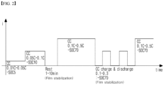
- FIG. 2 is a graph showing an example of the primary charging of step (c) in a method of producing a lithium secondary battery according to an embodiment of the present invention according to a charging current and time.
- the stepwise charging may be firstly performed by gradually increasing a C-rate in a low current C-rate range of 0.01 to 0.5C from SOC 0% to SOC 70% in the primary charging.
- the C-rate may be selected in a low charging current range of 0.01C to 0.05C as described above, and charging proceeds up to SOC 5%.
- charging is performed by increasing a charging current in a relatively higher C-rate range of 0.05 to 0.1C up to SOC 10%.
- charging may proceed at a C-rate of 0.1 to 0.5C, which is relatively higher than that in the second charging step, up to SOC 70%.
- a pause section is included between the second charging step and the third charging step to stabilize a film.
- the primary charging is terminated with the stepwise charging, and then a degassing process may be performed.
- pulse charging and discharging in which charging and discharging are repeated at a charging current of 0.1 to 0.3C in an SOC range of 0 to 70% is performed to achieve film stabilization.
- the stepwise charging may proceed again at a higher C-rate than charging current in the pulse charging and discharging (e.g., at the same C-rate as charging current in the third charging step) up to SOC 70%.
- modified stepwise charging or modified stepwise charging & pulse charging and discharging may be performed in a range capable of stably, more uniformly, and densely forming and maintaining a SEI film.
- the primary charged battery cell is degassed to remove gas inside the battery cell.
- the degassing may be performed by opening an electrolyte inlet of a battery case in the primary charging.
- the degassing process may include a process of discharging gas through an outlet formed in a portion (gas pocket) of a battery case and fusing the outlet.
- the degassing process is capable of removing gas generated during the primary charging, but when a large amount of gas is generated, gas is not completely discharged, and thus some gas may remain in a battery cell.
- the present invention employs a method of reducing a gas generation amount through the stepwise charging or the stepwise charging & pulse charging and discharging as described above at the beginning. Also, although gas is discharged in the degassing process, when gas is generated due to a solvent reaction of a second electrolyte in injection of the second electrolyte as described below, the degassing process may not be performed again, and thus the gas may not be discharged.
- a SEI film is formed so as to uniformly cover an electrode in the primary charging by including the additive for forming a SEI film in the injection of the first electrolyte, and particularly, the SEI film is more densely and uniformly formed by the stepwise charging or the stepwise charging & pulse charging and discharging, a solvent reaction caused by injecting a second electrolyte is suppressed by the SEI film as much as possible, and thus a gas generation amount is further reduced.
- step (e) of the method of producing a lithium secondary battery according to the present invention a second electrolyte not including an additive for forming a SEI film is injected into the degassed battery cell.
- the total amount of the first electrolyte and the second electrolyte is determined to be a set value required for charging and discharging a battery cell as a product.
- the second electrolyte may be used in a weight ratio of 60 to 80% relative to the first electrolyte (20 to 40%). Since the SEI film is uniformly and stably formed due to the additive of the first electrolyte, an additive for forming a SEI film is not included in the second electrolyte. Therefore, even when a larger amount of the second electrolyte is injected compared to the first electrolyte as described above, the SEI film may prevent a reaction between the electrode and the second electrolyte to reduce a gas generation amount.
- the second electrolyte includes a non-aqueous organic solvent and a lithium salt.
- the non-aqueous organic solvent and lithium salt of the second electrolyte may be the same as or different from the organic solvent and lithium salt included in the first electrolyte.
- aging may be further performed for impregnation of the second electrolyte and film stabilization.
- the aging may be performed at a higher temperature than that in the pre-aging.
- the aging may be repeatedly performed at room temperature and a high temperature.
- a SEI film may be further stabilized by thermal energy and electrochemical energy and uniformly formed with a uniform thickness without partiality.
- the battery which has been subjected to the high-temperature aging is secondarily charged, for example, at a charging current of 0.2 to 1C until 100% of designed battery capacity is reached. That is, charging as much as the capacity (SOC) remaining after the primary charging may be performed.
- SOC capacity
- a lithium secondary battery may be produced by the above-described method of producing a lithium secondary battery, and therefore, the present invention provides a lithium secondary battery produced by the above-described method.
- the lithium secondary battery according to the present invention is preferably used not only in a battery cell used as a power source of small-sized devices but also as a unit cell of a medium-to-large-sized battery module including a plurality of battery cells.
- Preferred examples of the medium-to-large-sized devices include electric vehicles, hybrid electric vehicles, plug-in hybrid electric vehicles, power storage systems, and the like, but the present invention is not limited thereto.
- a porous polyethylene separator was interposed between the above manufactured positive electrode and negative electrode, and the resultant was accommodated in a pouch-type case to produce a battery cell.
- An electrolyte in which 1M LiPF 6 was dissolved in a solvent obtained by mixing ethylene carbonate (EC) and ethyl methyl carbonate (EMC) in a volume ratio of 30:70 was prepared as a first electrolyte, wherein vinylene carbonate (based on a carbonate) and propane sultone (based on sulfur) as additives for forming a SEI film were included each in an amount of 3 wt% with respect to the total weight of the first and second electrolytes in the electrolyte.
- the first electrolyte was injected into the battery of Preparation Example, and the resulting battery was pre-aged at room temperature for 2 days.
- the battery cell was subjected to three-step charging including a first charging step at 0.01C up to SOC 0 to 2%, a second charging step at 0.1C up to SOC 2 to 5%, and a third charging step at 0.2C up to SOC 5 to 70% while gradually increasing charging current and SOC. A pause for a minute was included between the second charging step and the third charging step.
- a pressure of 5 kgf/cm 2 was applied to the primary charged battery cell to remove gas, and a second electrolyte including the same organic solvent and lithium salt as those of the first electrolyte was injected into the battery case.
- a weight ratio of the first electrolyte and the second electrolyte was 30:70.
- the second electrolyte was injected, and the resultant was aged at room temperature for 12 hours and at 60 °C for 12 hours to produce a lithium secondary battery.
- a battery cell of Example 2 was produced in the same manner as in Example 1 except for the primary charging conditions. That is, the battery cell was subjected to a first charging step at 0.01C up to SOC 0 to 2% and a second charging step at 0.1C up to SOC 2 to 5% and then paused for a minute. Afterward, the battery cell was subjected to pulse charging and discharging in which charging and discharging were repeated 5 times at 0.1C in a SOC range of 0 to 5% and then paused for a minute. Finally, the battery cell was charged again at 0.2C from SOC 5% to SOC 70%.
- a lithium secondary battery of Example 2 was produced under the same conditions for gas removal after primary charging, second electrolyte injection, and aging as in Example 1.
- a battery cell of Comparative Example 1 was produced under the same conditions as in Example 1 except that different primary charging conditions were applied to the battery cell of Preparation Example.
- primary charging was performed at a charging current of 0.2C (constant current) up to SOC 70% without performing the stepwise charging as in Example 1 and the stepwise charging & pulse charging and discharging as in Example 2.
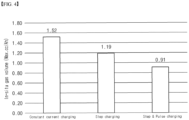
- FIG. 4 is a graph showing the comparison of maximum gas generation amounts of Examples 1 and 2 and Comparative Example 1.
- a SEI film is more robustly and densely formed or stabilized by combining separate injection and stepwise charging or by combining separate injection and stepwise charging & pulse charging and discharging, and thus the amount of gas generated by a solvent reaction between the electrolyte and the electrode can be substantially reduced.
- Each battery cell of Examples 1 and 2 and Comparative Example 1 was charged at a constant current of 0.2 C and a constant voltage (CC-CV) up to SOC 100% and SOC 20% to produce a final battery cell.
- CC-CV constant voltage
- the impedance of the battery cell was measured by inputting alternating current signals of various frequencies using an impedance analyzer.
- FIG. 5 is a graph showing the impedance measurement data for each frequency of the final battery cells produced according to Examples 1 and 2 and Comparative Example 1.
- the impedance analyzer measures the impedance of the battery cell for each frequency using electrochemical impedance spectroscopy (EIS) under a plurality of predetermined frequency conditions.
- EIS electrochemical impedance spectroscopy
- the frequency condition of the EIS impedance analyzer was 0.01 to 10,000 Hz, and the amplitude was 5 to 10 mV.
- Example 1 As shown in FIG. 5 , it can be confirmed that the impedance of the battery cell of Example 1 in which stepwise charging was performed was lower than that of Comparative Example 1 in which charging at a constant current was performed, and the impedance of Example 2 was lower than that of Example 1.
Landscapes
- Chemical & Material Sciences (AREA)
- Chemical Kinetics & Catalysis (AREA)
- Electrochemistry (AREA)
- General Chemical & Material Sciences (AREA)
- Engineering & Computer Science (AREA)
- Manufacturing & Machinery (AREA)
- General Physics & Mathematics (AREA)
- Physics & Mathematics (AREA)
- Condensed Matter Physics & Semiconductors (AREA)
- Inorganic Chemistry (AREA)
- Materials Engineering (AREA)
- Secondary Cells (AREA)
- Battery Electrode And Active Subsutance (AREA)
Abstract
Description
- The present invention relates to a method of producing a lithium secondary battery for reducing the generation of gas during an activation process, and a lithium secondary battery produced thereby.
- More specifically, the present invention relates to a method of producing a lithium secondary battery, which is intended to minimize an amount of activation gas generated by a reaction between a solvent of an electrolyte and an electrode by uniformly and stably forming a solid electrolyte interface (SEI) film by improving an electrolyte injection process and a primary charging process in the production of a lithium secondary battery.
- This application claims the benefit of priority based on
Korean Patent Application No. 10-2021-0076579, filed on June 14, 2021 - As the technology for mobile devices is developed and the demand for mobile devices increases, the demand for secondary batteries as a power source is rapidly increasing, and among secondary batteries, lithium secondary batteries having a high energy density, a high action potential, a long cycle lifespan, and a low self-discharge rate have been commercialized and widely used.
- As interest in environmental issues has increased in recent years, many studies have been conducted on electric vehicles (EVs), hybrid electric vehicles (HEVs), and the like which are able to replace vehicles using fossil fuels, such as gasoline and diesel vehicles, which are one of the main causes of air pollution.
- Although nickel-metal hydride (Ni-MH) secondary batteries have been mainly used as a power source of the EVs, HEVs, and the like, studies on the use of lithium secondary batteries having a high energy density, high discharge voltage, and output stability are being actively conducted, and some of them have been commercialized.
- The lithium secondary battery is a battery composed of a positive electrode, a negative electrode, an electrolyte that provides the migration path of lithium ions between the positive electrode and the negative electrode, and a separator, and charging and discharging proceed by repeating a process of intercalating and deintercalating lithium ions from a lithium metal oxide of the positive electrode to a carbon-based negative electrode. In this case, lithium reacts with the carbon electrode due to having high reactivity to produce Li2CO3, LiO, LiOH, or the like, and thus a film is formed on the surface of the negative electrode. This film is referred to as a solid electrolyte interface (SEI) film, and a SEI film formed during initial charging prevents a reaction of lithium ions with the carbon negative electrode or other materials during charging and discharging. Also, the SEI film acts as an ion tunnel to allow only lithium ions to pass through. The ion tunnel serves to solvate lithium ions and thus prevent the collapse of a structure of the carbon negative electrode due to the co-intercalation of the lithium ion and an organic solvent, which is contained in an electrolyte, have a high molecular weight, and move along with the lithium ions, to the carbon negative electrode.
- Therefore, in order to enhance the high-temperature cycle characteristics and low-temperature output characteristics of lithium secondary batteries, it is necessary to form a robust SEI film on the negative electrode of lithium secondary batteries.
- However, there is a problem in that an organic solvent in an electrolyte reacts with the surface of an electrode, for example, a negative electrode, during initial charging in an activation process to generate gas. The generated gas is trapped inside a battery to cause capacity degradation and lithium precipitation. Also, since the gas is generated or consumed by an additional reaction during an aging process, it is important to minimize a gas generation amount during initial charging.
- In addition, the SEI film formed during initial charging may not be stably maintained or uniformly formed according to charging conditions. When the SEI film is not stabilized, an organic solvent in an electrolyte reacts with an electrode again to generate gas, repeating the vicious cycle.
- Therefore, there is a need to develop a technology that is capable of minimizing gas generation while forming a uniform and robust SEI film.
-
Korean Laid-Open Patent Publication No. 10-2017-0034774 - One object of the present invention is to provide a method of producing a lithium secondary battery, which is capable of reducing a gas generation amount by stably forming a SEI film by improving an electrolyte injection process and a primary charging process in production of a lithium secondary battery.
- Another object of the present invention is to provide a lithium secondary battery produced by the above-described method of producing a lithium secondary battery.
- In order to solve the above problem, one aspect of the present invention provides a method of producing a lithium secondary battery, which includes:
- (a) injecting a first electrolyte including an additive for forming a solid electrolyte interface (SEI) film into a battery cell in which an electrode assembly including a positive electrode, a negative electrode, and a separator interposed between the positive electrode and the negative electrode is accommodated in a battery case;
- (b) pre-aging the battery cell containing the first electrolyte injected thereinto;
- (c) primary charging the pre-aged battery cell so that a predetermined state of charge (SOC) is reached to activate the battery cell;
- (d) degassing the primary charged battery cell to remove gas inside the battery cell; and
- (e) injecting a second electrolyte not including the additive for forming a SEI film into the degassed battery cell,
- Another aspect of the present invention provides a lithium secondary battery produced by the above-described method.
- According to a method of producing a lithium secondary battery of the present invention, a SEI film is stably formed due to an additive for forming a SEI film in injection of a first electrolyte so as to suppress a reaction between an organic solvent and an electrode in injection of a second electrolyte, and thus the generation of gas due to the reaction can be minimized.
- In addition, the method allows a SEI film to be more easily formed by a stepwise charging process of gradually increasing the magnitude of a charging current or a stepwise charging & pulse charging and discharging in primary charging after injection of a first electrolyte, and also allows the formed SEI film to be stabilized, and thus gas generated during an activation process can be further reduced, and the resistance of a final battery cell produced by the method can be reduced.
-
-
FIG. 1 is a flowchart showing a method of producing a lithium secondary battery according to an embodiment of the present invention. -
FIG. 2 is a graph showing an example of primary charging of a step (c) in a method of producing a lithium secondary battery according to an embodiment of the present invention. -
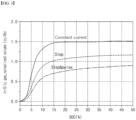
FIG. 3 is a graph showing the comparison of gas generation amounts of lithium secondary batteries produced according to Examples 1 and 2 of the present invention and Comparative Example 1. -
FIG. 4 is a graph showing the comparison of maximum gas generation amounts of Examples 1 and 2 and Comparative Example 1. -
FIG. 5 is a graph showing the impedance measurement data for each frequency of final battery cells produced according to Examples 1 and 2 and Comparative Example 1. - Hereinafter, the present invention will be described in further detail to help in understanding the present invention.
- Terms and words used in this specification and the claims should not be interpreted as being limited to commonly used meanings or meanings in dictionaries and should be interpreted with meanings and concepts which are consistent with the technological scope of the present invention based on the principle that the inventors can appropriately define concepts of terms in order to describe the invention in the best way.
- A method of producing a lithium secondary battery according to the present invention includes: (a) injecting a first electrolyte including an additive for forming a solid electrolyte interface (SEI) film into a battery cell in which an electrode assembly including a positive electrode, a negative electrode, and a separator interposed between the positive electrode and the negative electrode is accommodated in a battery case; (b) pre-aging the battery cell containing the first electrolyte injected thereinto; (c) primary charging the pre-aged battery cell so that a predetermined state of charge (SOC) is reached to activate the battery cell; (d) degassing the primary charged battery cell to remove gas inside the battery cell; and (e) injecting a second electrolyte not including the additive for forming a SEI film into the degassed battery cell, wherein the primary charging includes a stepwise charging process performed by gradually increasing the magnitude of a charging current according to the SOC of the battery cell.
-
FIG. 1 is a flowchart showing a method of producing a lithium secondary battery according to an embodiment of the present invention. - Hereinafter, each step will be described in further detail with reference to
FIG. 1 . - First, in step (a), a first electrolyte including an additive for forming a SEI film is injected into a battery cell in which an electrode assembly including a positive electrode, a negative electrode, and a separator interposed between the positive electrode and the negative electrode is accommodated in a battery case.
- The electrode assembly may be manufactured by a method typically known in the art.
- The positive electrode in the electrode assembly has a structure in which a positive electrode mixture layer is stacked on one surface or both surfaces of an electrode current collector. As one example, the positive electrode mixture layer includes a conductive material, a binder polymer, and the like in addition to a positive electrode active material, and a positive electrode additive typically used in the art may be further included as necessary.
- The positive electrode active material may be a lithium-containing oxide, and the same or different positive electrode active materials may be used. As the lithium-containing oxide, a lithium-containing transition metal oxide may be used.
- For example, the lithium-containing transition metal oxide may be any one or a mixture of two or more selected from the group consisting of LixCoO2 (0.5<x<1.3), LixNiO2 (0.5<x<1.3), LixMnO2 (0.5<x<1.3), LixMn2O4 (0.5<x<1.3), Lix(NiaCobMnc)O2 (0.5<x<1.3, 0<a<1, 0<b<1, 0<c<1, a+b+c=1), LixNi1-yCoyO2 (0.5<x<1.3, 0<y<1), LixCo1-yMnyO2 (0.5<x<1.3, 0≤y<1), LixNi1-yMnyO2 (0.5<x<1.3, 0≤y<1), Lix(NiaCobMnc)O4 (0.5<x<1.3, 0<a<2, 0<b<2, 0<c<2, a+b+c=2), LixMn2-zNizO4 (0.5<x<1.3, 0<z<2), LixMn2-zCozO4 (0.5<x<1.3, 0<z<2), LixCoPO4 (0.5<x<1.3), and LixFePO4 (0.5<x<1.3) , but the present invention is not limited thereto. Also, the lithium-containing transition metal oxide may be coated with a metal such as aluminum (Al) or a metal oxide. Also, in addition to the lithium-containing transition metal oxide, one or more of sulfides, selenides, and halides may be used.
- A current collector used in the positive electrode may be used without limitation as long as it is a metal with high conductivity, to which a positive electrode active material slurry is able to be easily adhered and which has no reactivity in the voltage range of a secondary battery. For example, copper, stainless steel, aluminum, nickel, titanium, calcined carbon, copper or stainless steel whose surface has been treated with carbon, nickel, titanium, silver, or the like, an aluminum-cadmium alloy, or the like may be used. The current collector may be used in any of various forms such as a film, a sheet, a foil, a net, a porous material, a foam, and a non-woven fabric and have a thickness of 3 to 500 µm.
- Examples of a solvent for forming the positive electrode include water and an organic solvent such as N-methyl pyrrolidone (NMP), dimethylformamide (DMF), acetone, dimethylacetamide, and the like, and these solvents may be used alone or in combination of two or more thereof. The solvent is used in an amount sufficient to dissolve and disperse the positive electrode active material, the binder, and the conductive material in consideration of the thickness of an applied slurry and manufacturing yield.
- As the binder, various types of binder polymers such as polyvinylidene fluoride-co-hexafluoropropylene (PVDF-co-HFP), polyvinylidene fluoride, polyacrylonitrile, polymethyl methacrylate, polyvinyl alcohol, carboxymethylcellulose (CMC), starch, hydroxypropyl cellulose, regenerated cellulose, polyvinylpyrrolidone, polytetrafluoroethylene, polyethylene, polypropylene, polyacrylic acid, an ethylene-propylene-diene monomer (EPDM), a sulfonated EPDM, styrene butadiene rubber (SBR), fluoro-rubber, polyacrylic acid, a polymer whose hydrogens have been substituted with Li, Na, Ca, or the like, and various copolymers thereof may be used.
- The conductive material is not particularly limited as long as it does not cause a chemical change in the battery and has conductivity. For example, graphite such as natural graphite, artificial graphite, or the like; carbon black such as acetylene black, Ketjen black, channel black, furnace black, lamp black, thermal black, or the like; a conductive fiber such as carbon fiber, metal fiber, or the like; a conductive tube such as carbon nanotubes or the like; fluorocarbon powder; metal powder such as aluminum powder, nickel powder, or the like; a conductive whisker such as zinc oxide, potassium titanate, or the like; a conductive metal oxide such as titanium oxide or the like; or a conductive material such as a polyphenylene derivative or the like may be used. The conductive material may be used in an amount of 1 wt% to 20 wt% with respect to the total weight of the positive electrode slurry.
- The negative electrode has a structure in which a negative electrode active material layer is stacked on one surface or both surfaces of a negative electrode current collector. As one example, the negative electrode active material layer includes a negative electrode active material, a conductive material, a binder polymer, and the like, and a negative electrode additive typically used in the art may be further included as necessary.
- The negative electrode active material may include a carbonaceous material, lithium metal, silicon, tin, or the like. When a carbonaceous material is used as the negative electrode active material, both low-crystallinity carbon and high-crystallinity carbon may be used. Representative examples of the low-crystallinity carbon include soft carbon and hard carbon, and representative examples of the high-crystallinity carbon include natural graphite, Kish graphite, pyrolytic carbon, mesophase pitch-based carbon fiber, meso-carbon microbeads, mesophase pitches, and high-temperature calcined carbon such as petroleum or coal tar pitch-derived cokes, and the like.
- Non-limiting examples of a current collector used in the negative electrode include a foil made of copper, gold, nickel, a copper alloy, and a combination thereof. Also, the current collector may be used by stacking substrates made of the above-described materials. Specifically, the negative electrode current collector is formed of the above-described metal component and includes a metal plate having a through hole formed in the thickness direction and an ion-conductive porous reinforcing material filled in the through hole of the metal plate.
- In addition, the negative electrode may include a conductive material and a binder which are typically used in the art.
- As the conductive material, a carbon-based conductive material is mainly used and includes a sphere-type or needle-type carbon-based conductive material. The sphere-type carbon-based conductive material fills the empty space (pore) between active material particles while being mixed with a binder so as to improve physical contact between active materials, thereby reducing interfacial resistance and enhancing adhesion between the lower positive electrode active material and the current collector. Examples of the sphere-type carbon-based conductive material include carbon black including Denka black.
- As the binder polymer, any binder typically used in the art may be used without limitation. For example, various types of binders such as polyvinylidene fluoride-co-hexafluoropropylene (PVDF-co-HFP), polyvinylidene fluoride (PVDF), polyacrylonitrile, polymethyl methacrylate, styrene butadiene rubber (SBR), carboxymethylcellulose (CMC), and the like may be used.
- An amount of the binder polymer is proportional to an amount of the conductive material included in the upper positive electrode active material layer and the lower positive electrode active material layer. This is because the binder polymer is intended to impart adhesion to the conductive material whose particle size is relatively smaller than that of the active material, and thus a larger amount of the binder polymer is required as an amount of the conductive material increases, and a smaller amount of the binder polymer is used as an amount of the conductive material decreases.
- As the separator, any separator may be used as long as it is a porous substrate used in a lithium secondary battery. For example, a polyolefin-based porous membrane or a non-woven fabric may be used, but the present invention is not limited thereto. The polyolefin-based porous membrane is, for example, a membrane formed of one or a mixture of polyethylene such as high-density polyethylene, linear low-density polyethylene, low-density polyethylene, and ultra-high-molecular-weight polyethylene, and polyolefin-based polymers such as polypropylene, polybutylene, polypentene, and the like.
- Although there is no particular limitation on the thickness of the porous substrate, the thickness may be 5 to 50 µm. Also, although there is no particular limitation on the size and porosity of pores present in the porous substrate, the size and porosity may be 0.01 to 50 µm and 10 to 95%, respectively.
- Meanwhile, in order to enhance the mechanical strength of a separator composed of the porous substrate and suppress a short circuit between the positive electrode and the negative electrode, a porous coating layer including inorganic particles and a binder polymer may be further included on at least one surface of the porous substrate.
- The electrode assembly manufactured by the above method is inserted in a battery case. The battery case used in the present invention may be a battery case having the appearance of a cylindrical form, a prismatic form, a pouch form, or a coin form, and there is no particular limitation on the appearance thereof. A battery cell in which the electrode assembly is accommodated in the battery case is not a battery cell as a final product but a so-called fresh cell.
- An electrolyte to be injected into a lithium secondary battery of the present invention is divided into a first electrolyte including an additive for forming a SEI film and a second electrolyte not including an additive for forming a SEI film, and a predetermined amount of the first electrolyte is injected into a lithium secondary battery in step (a).
- The first electrolyte may include a non-aqueous organic solvent and a lithium salt, and since the first electrolyte includes an additive for forming a SEI film, a stable SEI film may be formed on a carbon negative electrode surface in primary charging to be described below due to the additive.
- The non-aqueous organic solvent is not limited as long as it is capable of minimizing decomposition caused by an oxidation reaction in a charging/discharging process of a battery and may be, for example, one or a mixture of two or more selected from the group consisting of a cyclic carbonate, a linear carbonate, an ester, an ether, and a ketone.
- Among the organic solvents, especially, a carbonate-based organic solvent is preferably used. Examples of the cyclic carbonate include ethylene carbonate (EC), propylene carbonate (PC), and butylene carbonate (BC) and representative examples of the linear carbonate include dimethyl carbonate (DMC), diethyl carbonate (DEC), dipropyl carbonate (DPC), ethyl methyl carbonate (EMC), methyl propyl carbonate (MPC), and ethyl propyl carbonate (EPC).
- As the lithium salt, any lithium salt typically used in an electrolyte of a lithium secondary battery, such as LiPF6, LiAsF6, LiCF3SO3, LiN(CF3SO2)2, LiBF4, LiBF6, LiSbF6, LiN(C2F5SO2)2, LiAlO4, LiAlCl4, LiSO3CF3, and LiClO4, may be used without limitation, and these lithium salts may be used alone or in combination of two or more thereof.
- In addition, the first electrolyte includes an additive for forming a SEI film. The inclusion of an additive for forming a SEI film in the first electrolyte is intended to uniformly form a SEI film on the entire surface of an electrode, specifically, a negative electrode, before the injection of a relatively large amount of a second electrolyte. As described below, the additive is decomposed to form a SEI film on an electrode in primary charging after the injection of the first electrolyte. When the SEI film is uniformly and densely formed so as to cover the entire surface of an electrode, even when a second electrolyte is injected, gas generation caused by a reaction between the electrolyte and the electrode can be substantially reduced.
- The additive for forming a SEI film may be one or a mixture of two or more selected from the group consisting of vinylene carbonate (VC), vinyl ethylene carbonate (VEC), fluoroethylene carbonate (FEC), cyclic sulfite, saturated sultone, unsaturated sultone, non-cyclic sulfone, lithium oxalyldifluoroborate (LiODFB), and a derivative thereof. Specifically, as a sulfur (S)-based additive, propane sultone (PS), 1-3 propene sultone (PRS), ethylene sulfate (ESa), or the like may be used.
- The additive for forming a SEI film is preferably included in an amount of 0.1 to 10 wt% with respect to the total weight of the first electrolyte. When the amount of the additive is less than 0.1 wt%, the effect of the additive is insignificant, and when the amount of the additive exceeds 10 wt%, the additive is decomposed to generate gas.
- The first electrolyte is included in an amount sufficient to serve to transfer the additive for forming a SEI film onto an electrode and ensure the wettability of an electrode. Also, when a large amount of the first electrolyte is injected, the electrolyte may react with an electrode to generate a large amount of gas. Therefore, an amount of the first electrolyte may be appropriately determined in view of ensuring electrode wettability and preventing gas generation. That is, the first electrolyte and the second electrolyte may be used in a weight ratio of 20:80 to 40:60, more specifically, 20:80 to 70:30. When the proportion of the first electrolyte is less than 20%, electrode wettability is degraded, and thus it is difficult to perform a smooth charging reaction in primary charging, and when the proportion of the first electrolyte exceeds 40%, gas is generated, and thus the formation of a SEI film is hindered.
- Next, in step (b), the battery cell containing the first electrolyte injected thereinto is pre-aged.
- The pre-aging is performed to allow the first electrolyte to be sufficiently impregnated into an electrode of the battery cell, that is, to enhance wettability. The pre-aging is performed, for example, at room temperature for 1 to 3 days, but the present invention is not limited thereto. In order to enhance wettability, the pre-aging may be performed at a temperature below and above room temperature (e.g., 25±5 °C), and as a pre-aging temperature increases, a pre-aging time may decrease proportionally thereto. Therefore, the pre-aging temperature and time may be appropriately determined under conditions suitable for impregnation of the first electrolyte in consideration of an amount of the electrolyte.
- Next, in step (c), the pre-aged cell is primary charged so that a predetermined state of charge (SOC) is reached to activate the cell (formation). In the present invention, the primary charging is a very important process for stably forming a SEI film and minimizing gas generation in addition to step (a) of including the additive for forming a SEI film. This process stabilizes the structure of the battery cell and makes it usable.
- In the primary charging, lithium ions from a positive electrode active material move and are intercalated into a negative electrode active material. In this case, lithium ions react with an electrolyte in a negative electrode due to having high reactivity to produce a compound such as Li2CO3, LiO, LiOH, or the like, and the compound forms a SEI film on the negative electrode surface. In this process, the additive for forming a SEI film included in the first electrolyte is decomposed to help the formation of a SEI film on the electrode.
- When an SOC increases up to 100% in the primary charging, the capacity of a finally produced battery cell increases. However, since the battery cell of the present invention is a fresh cell, when charging proceeds up to SOC 100% in the primary charging, lithium is precipitated to degrade battery characteristics.
- Therefore, charging preferably proceeds up to the most appropriate predetermined SOC in the primary charging in consideration of the capacity of a produced battery cell and prevention of lithium precipitation. For example, the predetermined SOC may be appropriately selected in a range of at most 70%, that is, 70% or less. When an SOC exceeds 70% in the primary charging, lithium precipitation is caused as described above. Therefore, the primary charging preferably proceeds until a maximum SOC value reaches 70% or less.
- In the present invention, the primary charging includes a stepwise charging process performed by gradually increasing the magnitude of a charging current according to the SOC of the battery cell. That is, a stepwise charging method in which charging is performed by gradually increasing the magnitude of a charging current according to an SOC value (magnitude) is employed instead of a charging at once by applying a constant current or constant voltage up to SOC 70%. This is intended to stably form a film on a negative electrode by easily decomposing the additive for forming a SEI film included in the first electrolyte. When charging is performed with an excessive SOC or excessive charging current at the beginning, charging may proceed while the additive for forming a SEI film is not completely decomposed, and thus the formed SEI film is not uniform and may be broken. In particular, when charging proceeds at a high charging current in a low SOC range, a gas generation amount increases as described below.
- Therefore, the present invention employs a stepwise charging process of gradually increasing the magnitude of a charging current according to the SOC of the battery cell.
- A charging current in the stepwise charging process may be selected in a low current range of 0.01 to 0.5C. That is, even when charging current is gradually increased, it is preferable that a maximum charging current does not exceed 0.5C in consideration of the formation and stabilization of a SEI film. Also, when charging proceeds at a low current of 0.01C to 0.5C, the film formation reaction of the additive for forming a SEI film may be sufficiently induced. When charging proceeds at a current below 0.01C, an excessive amount of time is consumed for charging, and therefore, charging in the above low current range is preferred.
- In the stepwise charging process, the charging current of a first step, which is the lowest, may be selected in a range of 0.01 to 0.05C. Generally, a carbonate-based or sulfur (S)-based additive for forming a SEI film is easily decomposed in the above low current range of 0.01 to 0.05C. When charging proceeds at a charging current above 0.05C, the additive may be insufficiently decomposed, and thus it is preferable that the charging current of a first step is selected in the above range for a sufficient reaction of the additive.
- Meanwhile, a charging pause for stabilizing a SEI film is preferably included at least once between specific steps of the stepwise charging process. The duration of the pause may be appropriately determined according to the type and amount of an additive, the type and amount of an electrolyte, and the like. For example, the pause may last for an appropriate time in a time range of 1 to 10 minutes.
- The number of steps in the stepwise charging process may be determined in an appropriate range for film stabilization. For example, the stepwise charging may be performed by gradually increasing a charging current in at least 2 to 3 steps, but the present invention is not limited thereto. The number of times of the pause may also be determined in an appropriate range for film stabilization, and the pause may be included at least once. In principle, there is no limitation at which steps the pause is included between. However, since the pause is intended to stabilize a film, it is necessary to satisfy a film formation condition, and thus the pause needs to be included at least after a first step of the stepwise charging process.
- According to the method of producing a lithium secondary battery of an embodiment of the present invention, in the primary charging, pulse charging and discharging in which charging and discharging are repeated at a predetermined C-rate is performed after the stepwise charging process or between specific steps of the stepwise charging process.
- When the pulse charging and discharging is performed as described above, a process of microscopically forming or decomposing a SEI film is repeated. This repetitive pulse charging and discharging may allow a SEI film to be more densely and uniformly formed on an electrode. It is favorable that the predetermined C-rate in the pulse charging and discharging is lower than the maximum C-rate in the stepwise charging process, but the present invention is not limited thereto. In order to perform faster charging and discharging and also rapidly reach a high SOC, in some cases, charging and discharging may proceed at a higher charging current than the maximum C-rate in the stepwise charging process. However, in any cases, it is necessary to perform charging up to an SOC value less than or equal to the maximum SOC (e.g., 70% or less) of an activation process.
- Meanwhile, it is preferable that each charging and discharging time in the pulse charging and discharging is also shorter than the duration of each step in the stepwise charging process. This is because, since the pulse charging and discharging is intended for further stabilization by microscopically forming and decomposing the SEI film formed in the stepwise charging process, when the duration of the pulse charging and discharging is longer than that of the stepwise charging process, the micro-behavior of the SEI film may be broken to degrade film stability. The pulse charging and discharging may be performed after a series of steps of the stepwise charging process, but it is also possible to perform the pulse charging and discharging between specific steps of the stepwise charging process as necessary.
- As described above, when the pulse charging and discharging is performed in the primary charging in addition to the stepwise charging, a SEI film is further stabilized, and thus a gas generation amount of a battery cell can be further reduced as described below.
- A charging pause for stabilizing a SEI film may be included at least once between specific steps of the stepwise charging process, between the stepwise charging process and the pulse charging and discharging, or after the pulse charging and discharging. The duration of the pause may be appropriately determined according to the type and amount of an additive, the type and amount of an electrolyte, and the like. For example, the pause may last for an appropriate time in a time range of 1 to 10 minutes.
-
FIG. 2 is a graph showing an example of the primary charging of step (c) in a method of producing a lithium secondary battery according to an embodiment of the present invention according to a charging current and time. - As shown in
FIG. 2 , the stepwise charging may be firstly performed by gradually increasing a C-rate in a low current C-rate range of 0.01 to 0.5C fromSOC 0% to SOC 70% in the primary charging. In the first charging step of the stepwise charging, the C-rate may be selected in a low charging current range of 0.01C to 0.05C as described above, and charging proceeds up toSOC 5%. Next, charging is performed by increasing a charging current in a relatively higher C-rate range of 0.05 to 0.1C up toSOC 10%. Then, charging may proceed at a C-rate of 0.1 to 0.5C, which is relatively higher than that in the second charging step, up to SOC 70%. In this embodiment, a pause section is included between the second charging step and the third charging step to stabilize a film. In an embodiment of the present invention, the primary charging is terminated with the stepwise charging, and then a degassing process may be performed. - However, in an embodiment shown in
FIG. 2 , after the stepwise charging, pulse charging and discharging in which charging and discharging are repeated at a charging current of 0.1 to 0.3C in an SOC range of 0 to 70% is performed to achieve film stabilization. - Afterward, as shown in
FIG. 2 , the stepwise charging may proceed again at a higher C-rate than charging current in the pulse charging and discharging (e.g., at the same C-rate as charging current in the third charging step) up to SOC 70%. - Since the primary charging in the manner shown in
FIG. 2 is one exemplary embodiment, various types of modified stepwise charging or modified stepwise charging & pulse charging and discharging may be performed in a range capable of stably, more uniformly, and densely forming and maintaining a SEI film. - In step (d), the primary charged battery cell is degassed to remove gas inside the battery cell. In order to remove gas, the degassing may be performed by opening an electrolyte inlet of a battery case in the primary charging. Alternatively, when a pouch-type battery cell is used, the degassing process may include a process of discharging gas through an outlet formed in a portion (gas pocket) of a battery case and fusing the outlet. As described above, the degassing process is capable of removing gas generated during the primary charging, but when a large amount of gas is generated, gas is not completely discharged, and thus some gas may remain in a battery cell. Therefore, the present invention employs a method of reducing a gas generation amount through the stepwise charging or the stepwise charging & pulse charging and discharging as described above at the beginning. Also, although gas is discharged in the degassing process, when gas is generated due to a solvent reaction of a second electrolyte in injection of the second electrolyte as described below, the degassing process may not be performed again, and thus the gas may not be discharged. In the present invention, since a SEI film is formed so as to uniformly cover an electrode in the primary charging by including the additive for forming a SEI film in the injection of the first electrolyte, and particularly, the SEI film is more densely and uniformly formed by the stepwise charging or the stepwise charging & pulse charging and discharging, a solvent reaction caused by injecting a second electrolyte is suppressed by the SEI film as much as possible, and thus a gas generation amount is further reduced.
- Referring to
FIG. 1 again, in step (e) of the method of producing a lithium secondary battery according to the present invention, a second electrolyte not including an additive for forming a SEI film is injected into the degassed battery cell. - The total amount of the first electrolyte and the second electrolyte is determined to be a set value required for charging and discharging a battery cell as a product. As described above, the second electrolyte may be used in a weight ratio of 60 to 80% relative to the first electrolyte (20 to 40%). Since the SEI film is uniformly and stably formed due to the additive of the first electrolyte, an additive for forming a SEI film is not included in the second electrolyte. Therefore, even when a larger amount of the second electrolyte is injected compared to the first electrolyte as described above, the SEI film may prevent a reaction between the electrode and the second electrolyte to reduce a gas generation amount.
- The second electrolyte includes a non-aqueous organic solvent and a lithium salt. The non-aqueous organic solvent and lithium salt of the second electrolyte may be the same as or different from the organic solvent and lithium salt included in the first electrolyte.
- As an embodiment, after the injection of the second electrolyte, aging may be further performed for impregnation of the second electrolyte and film stabilization.
- Since the SEI film is uniformly and robustly formed by the above-described process, the aging may be performed at a higher temperature than that in the pre-aging. Alternatively, the aging may be repeatedly performed at room temperature and a high temperature. When aging is performed at a high temperature, for example, when the battery cell was allowed to stand at a high temperature of 45 to 60 °C for a half-day or 1 to 2 days, a SEI film may be further stabilized by thermal energy and electrochemical energy and uniformly formed with a uniform thickness without partiality.
- The battery which has been subjected to the high-temperature aging is secondarily charged, for example, at a charging current of 0.2 to 1C until 100% of designed battery capacity is reached. That is, charging as much as the capacity (SOC) remaining after the primary charging may be performed.
- A lithium secondary battery may be produced by the above-described method of producing a lithium secondary battery, and therefore, the present invention provides a lithium secondary battery produced by the above-described method.
- The lithium secondary battery according to the present invention is preferably used not only in a battery cell used as a power source of small-sized devices but also as a unit cell of a medium-to-large-sized battery module including a plurality of battery cells.
- Preferred examples of the medium-to-large-sized devices include electric vehicles, hybrid electric vehicles, plug-in hybrid electric vehicles, power storage systems, and the like, but the present invention is not limited thereto.
- Hereinafter, examples and experimental examples will be described for more specifically describing the present invention, but the present invention is not limited to the following examples and experimental examples. Examples of the present invention may be modified into various other forms, and the scope of the present invention is not limited to the examples to be described below. The examples of the present invention are provided so that this disclosure will be thorough and complete, and will fully convey the concept of embodiments to those skilled in the art.
- 97 parts by weight of Li[Ni0.6Mn0.2Co0.2]O2 that functions as a positive electrode active material, 1.5 parts by weight of graphite that functions as a conductive material, and 1.5 parts by weight of polyvinylidene fluoride (PVdF) that functions as a binder were mixed to prepare a positive electrode mixture. The obtained positive electrode mixture was dispersed in N-methyl-2-pyrrolidone that functions as a solvent to prepare a positive electrode slurry. The slurry was applied onto both surfaces of a 20 µm-thick aluminum foil as a positive electrode current collector, dried, and pressed to manufacture a positive electrode.
- 96.5 parts by weight of artificial graphite and natural graphite (weight ratio: 90:10) that function as negative electrode active materials, 2 parts by weight of styrene butadiene rubber (SBR) that functions as a binder, and 1.5 parts by weight of carboxymethylcellulose (CMC) were mixed to prepare a negative electrode mixture. The negative electrode mixture was dispersed in ion exchanged water that functions as a solvent to prepare a negative electrode slurry. The slurry was applied onto both surfaces of a 20 µm-thick copper foil as a negative electrode current collector, dried, and pressed to manufacture a negative electrode.
- A porous polyethylene separator was interposed between the above manufactured positive electrode and negative electrode, and the resultant was accommodated in a pouch-type case to produce a battery cell.
- An electrolyte in which 1M LiPF6 was dissolved in a solvent obtained by mixing ethylene carbonate (EC) and ethyl methyl carbonate (EMC) in a volume ratio of 30:70 was prepared as a first electrolyte, wherein vinylene carbonate (based on a carbonate) and propane sultone (based on sulfur) as additives for forming a SEI film were included each in an amount of 3 wt% with respect to the total weight of the first and second electrolytes in the electrolyte.
- The first electrolyte was injected into the battery of Preparation Example, and the resulting battery was pre-aged at room temperature for 2 days.
- Afterward, the battery cell was subjected to three-step charging including a first charging step at 0.01C up to
SOC 0 to 2%, a second charging step at 0.1C up to SOC 2 to 5%, and a third charging step at 0.2C up toSOC 5 to 70% while gradually increasing charging current and SOC. A pause for a minute was included between the second charging step and the third charging step. - A pressure of 5 kgf/cm2 was applied to the primary charged battery cell to remove gas, and a second electrolyte including the same organic solvent and lithium salt as those of the first electrolyte was injected into the battery case. A weight ratio of the first electrolyte and the second electrolyte was 30:70.
- The second electrolyte was injected, and the resultant was aged at room temperature for 12 hours and at 60 °C for 12 hours to produce a lithium secondary battery.
- A battery cell of Example 2 was produced in the same manner as in Example 1 except for the primary charging conditions. That is, the battery cell was subjected to a first charging step at 0.01C up to
SOC 0 to 2% and a second charging step at 0.1C up to SOC 2 to 5% and then paused for a minute. Afterward, the battery cell was subjected to pulse charging and discharging in which charging and discharging were repeated 5 times at 0.1C in a SOC range of 0 to 5% and then paused for a minute. Finally, the battery cell was charged again at 0.2C fromSOC 5% to SOC 70%. - A lithium secondary battery of Example 2 was produced under the same conditions for gas removal after primary charging, second electrolyte injection, and aging as in Example 1.
- A battery cell of Comparative Example 1 was produced under the same conditions as in Example 1 except that different primary charging conditions were applied to the battery cell of Preparation Example. In Comparative Example 1, primary charging was performed at a charging current of 0.2C (constant current) up to SOC 70% without performing the stepwise charging as in Example 1 and the stepwise charging & pulse charging and discharging as in Example 2.
- Experimental Example 1: Comparison of gas generation amount of battery cell
- When each battery cell of Examples 1 and 2 and Comparative Example 1 was immersed in a water tank containing silicone oil and charged in real time under the same conditions, gas was generated, and thus the volume of the battery cell was changed. This volume change was measured by a buoyancy measurement method. The gas volume was calculated by inverse calculation from the weight reduced due to the generation of buoyancy and is shown in
FIG. 3 . - Referring to
FIG. 3 , in the case of the battery cell of Comparative Example 1 in which primary charging at a constant current was performed, it can be confirmed that a large amount of gas was generated according to an SOC increase even when the first electrolyte and the second electrolyte were separately injected. On the other hand, in the case of the battery cell of Example 1 in which both separate injection and stepwise charging were performed, it can be confirmed that a smaller amount of gas was generated than in Comparative Example 1. Also, in the case of the battery cell of Example 2 in which all of separate injection, stepwise charging, and pulse charging and discharging were performed, it can be confirmed that the smallest amount of gas was generated. As shown inFIG. 3 , all of the battery cells showed that, when a maximum gas generation amount was reached, the amount of generated gas became saturated as the SOC increases. -
FIG. 4 is a graph showing the comparison of maximum gas generation amounts of Examples 1 and 2 and Comparative Example 1. - It can be confirmed that a maximum gas generation amount also decreased in the order of constant current charging, stepwise charging, and stepwise charging & pulse charging and discharging.
- From these results, it can be seen that a SEI film is more robustly and densely formed or stabilized by combining separate injection and stepwise charging or by combining separate injection and stepwise charging & pulse charging and discharging, and thus the amount of gas generated by a solvent reaction between the electrolyte and the electrode can be substantially reduced.
- Each battery cell of Examples 1 and 2 and Comparative Example 1 was charged at a constant current of 0.2 C and a constant voltage (CC-CV) up to SOC 100% and
SOC 20% to produce a final battery cell. - The impedance of the battery cell was measured by inputting alternating current signals of various frequencies using an impedance analyzer.
-
FIG. 5 is a graph showing the impedance measurement data for each frequency of the final battery cells produced according to Examples 1 and 2 and Comparative Example 1. The impedance analyzer measures the impedance of the battery cell for each frequency using electrochemical impedance spectroscopy (EIS) under a plurality of predetermined frequency conditions. The frequency condition of the EIS impedance analyzer was 0.01 to 10,000 Hz, and the amplitude was 5 to 10 mV. - As shown in
FIG. 5 , it can be confirmed that the impedance of the battery cell of Example 1 in which stepwise charging was performed was lower than that of Comparative Example 1 in which charging at a constant current was performed, and the impedance of Example 2 was lower than that of Example 1. - It is speculated that, since a more uniform and denser SEI film is formed by separate injection and stepwise charging and by separate injection and stepwise charging & pulse charging and discharging, the resistance (impedance) value of the battery cell also decreases.
Claims (16)
- A method of producing a lithium secondary battery, comprising:(a) injecting a first electrolyte including an additive for forming a solid electrolyte interface (SEI) film into a battery cell in which an electrode assembly including a positive electrode, a negative electrode, and a separator interposed between the positive electrode and the negative electrode is accommodated in a battery case;(b) pre-aging the battery cell containing the first electrolyte injected thereinto;(c) primary charging the pre-aged battery cell so that a predetermined state of charge (SOC) is reached to activate the battery cell;(d) degassing the primary charged battery cell to remove gas inside the battery cell; and(e) injecting a second electrolyte not including the additive for forming a SEI film into the degassed battery cell,wherein the primary charging includes a stepwise charging process performed by gradually increasing the magnitude of a charging current according to the SOC of the battery cell.
- The method of claim 1, wherein the first electrolyte includes a non-aqueous organic solvent and a lithium salt.
- The method of claim 2, wherein the non-aqueous organic solvent is one or a mixture of two or more selected from the group consisting of a cyclic carbonate, a linear carbonate, an ester, an ether, and a ketone.
- The method of claim 2, wherein the lithium salt is one or a mixture of two or more selected from the group consisting of LiPF6, LiAsF6, LiCF3SO3, LiN(CF3SO2)2, LiBF4, LiBF6, LiSbF6, LiN(C2F5SO2)2, LiAlO4, LiAlCl4, LiSO3CF3, and LiClO4.
- The method of claim 1, wherein the additive for forming a SEI film is one or a mixture of two or more selected from the group consisting of vinylene carbonate (VC), vinyl ethylene carbonate (VEC), fluoroethylene carbonate (FEC), cyclic sulfite, saturated sultone, unsaturated sultone, non-cyclic sulfone, lithium oxalyldifluoroborate (LiODFB), and a derivative thereof.
- The method of claim 1, wherein the additive for forming a SEI film is included in an amount of 0.1 to 10 wt% with respect to the total weight of the first electrolyte.
- The method of claim 1, wherein the second electrolyte includes a non-aqueous solvent and a lithium salt, and
the non-aqueous solvent and lithium salt of the second electrolyte are the same as or different from the non-aqueous solvent and lithium salt included in the first electrolyte. - The method of claim 1, wherein a weight ratio of the first electrolyte and the second electrolyte is 20:80 to 40:60.
- The method of claim 1, wherein a charging current in the stepwise charging process is selected in a low current range of 0.01 to 0.5C.
- The method of claim 9, wherein a charging current in a first step of the stepwise charging process is selected in a low current range of 0.01 to 0.05C.
- The method of claim 1, wherein the predetermined SOC is 70% or less.
- The method of claim 1, wherein a charging pause for stabilizing a SEI film is included at least once between specific steps of the stepwise charging process.
- The method of claim 1, wherein, in the primary charging, pulse charging and discharging in which charging and discharging are repeated at a predetermined C-rate is performed after the stepwise charging process or between specific steps of the stepwise charging process.
- The method of claim 13, wherein a charging pause for stabilizing a SEI film is included at least once between specific steps of the stepwise charging process, between the stepwise charging process and the pulse charging and discharging, or after the pulse charging and discharging.
- The method of claim 1, further comprising, after the step (e), aging the battery cell by maintaining the battery cell at room temperature and/or a high temperature for a predetermined time.
- A lithium secondary battery produced by the method according to claim 1.
Applications Claiming Priority (2)
| Application Number | Priority Date | Filing Date | Title |
|---|---|---|---|
| KR1020210076579A KR20220167519A (en) | 2021-06-14 | 2021-06-14 | Manufacturing method of lithium secondary battery |
| PCT/KR2022/003676 WO2022265187A1 (en) | 2021-06-14 | 2022-03-16 | Method for manufacturing lithium secondary battery |
Publications (3)
| Publication Number | Publication Date |
|---|---|
| EP4148856A1 true EP4148856A1 (en) | 2023-03-15 |
| EP4148856A4 EP4148856A4 (en) | 2024-11-13 |
| EP4148856B1 EP4148856B1 (en) | 2025-10-08 |
Family
ID=84527180
Family Applications (1)
| Application Number | Title | Priority Date | Filing Date |
|---|---|---|---|
| EP22813868.1A Active EP4148856B1 (en) | 2021-06-14 | 2022-03-16 | Method of producing lithium secondary battery |
Country Status (7)
| Country | Link |
|---|---|
| US (1) | US20240106009A1 (en) |
| EP (1) | EP4148856B1 (en) |
| KR (1) | KR20220167519A (en) |
| CN (1) | CN115943512A (en) |
| ES (1) | ES3058839T3 (en) |
| PL (1) | PL4148856T3 (en) |
| WO (1) | WO2022265187A1 (en) |
Families Citing this family (5)
| Publication number | Priority date | Publication date | Assignee | Title |
|---|---|---|---|---|
| WO2024136553A1 (en) * | 2022-12-23 | 2024-06-27 | 주식회사 엘지에너지솔루션 | Lithium secondary battery and manufacturing method therefor |
| CN120693695A (en) | 2023-02-15 | 2025-09-23 | 卡尔斯鲁厄技术研究所 | Methods and apparatus for forming electrochemical devices |
| DE102024110213A1 (en) | 2024-01-31 | 2025-07-31 | GM Global Technology Operations LLC | Process for producing preactivated lithium transition metal oxides for rechargeable batteries that cycle lithium ions |
| CN118472418B (en) * | 2024-05-28 | 2025-07-18 | 大连中比动力电池有限公司 | Electrolyte infiltration method for optimizing cylindrical battery |
| CN119725823B (en) * | 2025-02-26 | 2025-05-27 | 江苏天合储能有限公司 | Lithium ion battery formation method and lithium ion battery |
Family Cites Families (20)
| Publication number | Priority date | Publication date | Assignee | Title |
|---|---|---|---|---|
| JP3740323B2 (en) * | 1998-07-31 | 2006-02-01 | キヤノン株式会社 | Secondary battery charging method and apparatus |
| KR100555034B1 (en) * | 2003-06-18 | 2006-03-03 | 삼성에스디아이 주식회사 | Post Treatment Method of Lithium Secondary Battery |
| JP2006228651A (en) * | 2005-02-21 | 2006-08-31 | Sanyo Electric Co Ltd | Nonaqueous electrolyte secondary battery and its charging method |
| CN101315994B (en) * | 2007-05-31 | 2010-06-02 | 上海比亚迪有限公司 | Formation method for lithium ion secondary battery |
| JP5924552B2 (en) * | 2011-11-24 | 2016-05-25 | トヨタ自動車株式会社 | Non-aqueous electrolyte secondary battery and manufacturing method thereof |
| JP6058968B2 (en) * | 2012-10-15 | 2017-01-11 | トヨタ自動車株式会社 | Manufacturing method of secondary battery |
| CN104956522A (en) * | 2013-01-30 | 2015-09-30 | 那诺思卡乐康母庞特公司 | Phased introduction of lithium into the pre-lithiated anode of a lithium ion electrochemical cell |
| KR101732652B1 (en) * | 2014-09-30 | 2017-05-24 | 주식회사 엘지화학 | A method for manufacturing a Lithium ion Secondary Battery |
| KR102170026B1 (en) | 2015-09-21 | 2020-10-26 | 주식회사 엘지화학 | Preparing methode for lithium secondary battery having improved low temperature property and lithium secondary battery |
| KR102095969B1 (en) * | 2015-09-23 | 2020-04-01 | 주식회사 엘지화학 | Process of Manufacturing Secondary Battery Including Pre-wetting Process |
| KR102145492B1 (en) * | 2016-06-14 | 2020-08-18 | 주식회사 엘지화학 | Battery System with Improved Rate Characteristic and Method for Generating Battery System |
| JP7169526B2 (en) * | 2019-08-28 | 2022-11-11 | トヨタ自動車株式会社 | Method for manufacturing non-aqueous electrolyte secondary battery |
| JP2021044173A (en) * | 2019-09-12 | 2021-03-18 | アイシン精機株式会社 | Electrolyte for power storage device, power storage device, and manufacturing method of power storage device |
| CN110690509B (en) * | 2019-10-15 | 2020-11-06 | 宇恒电池有限公司 | Opening formation method of lithium ion battery |
| KR102821892B1 (en) * | 2019-11-19 | 2025-06-18 | 주식회사 엘지에너지솔루션 | Methods of activation for secondary battery |
| JP7223677B2 (en) * | 2019-11-29 | 2023-02-16 | プライムアースEvエナジー株式会社 | Method for manufacturing nickel-metal hydride storage battery |
| KR20210076579A (en) | 2019-12-16 | 2021-06-24 | (주)수정 | A removable cover for the wheels of a clean room conveyer and its fastening plate |
| CN111682272A (en) * | 2020-05-07 | 2020-09-18 | 惠州亿纬创能电池有限公司 | Lithium ion battery formation method and lithium ion battery |
| KR102773463B1 (en) * | 2020-05-22 | 2025-02-27 | 주식회사 엘지에너지솔루션 | Methods of activation for secondary battery |
| CN111554991B (en) * | 2020-06-10 | 2021-11-23 | 湖北亿纬动力有限公司 | Negative pressure formation method and battery |
-
2021
- 2021-06-14 KR KR1020210076579A patent/KR20220167519A/en active Pending
-
2022
- 2022-03-16 WO PCT/KR2022/003676 patent/WO2022265187A1/en not_active Ceased
- 2022-03-16 ES ES22813868T patent/ES3058839T3/en active Active
- 2022-03-16 PL PL22813868.1T patent/PL4148856T3/en unknown
- 2022-03-16 EP EP22813868.1A patent/EP4148856B1/en active Active
- 2022-03-16 CN CN202280005129.4A patent/CN115943512A/en active Pending
- 2022-03-16 US US18/009,907 patent/US20240106009A1/en active Pending
Also Published As
| Publication number | Publication date |
|---|---|
| KR20220167519A (en) | 2022-12-21 |
| US20240106009A1 (en) | 2024-03-28 |
| EP4148856A4 (en) | 2024-11-13 |
| EP4148856B1 (en) | 2025-10-08 |
| ES3058839T3 (en) | 2026-03-13 |
| PL4148856T3 (en) | 2026-02-23 |
| WO2022265187A1 (en) | 2022-12-22 |
| CN115943512A (en) | 2023-04-07 |
Similar Documents
| Publication | Publication Date | Title |
|---|---|---|
| US12107259B2 (en) | Negative electrode comprising a protective layer for a lithium secondary battery, method for manufacturing same, and lithium secondary battery including same | |
| EP4148856B1 (en) | Method of producing lithium secondary battery | |
| KR102516891B1 (en) | Anode for all solid state secondary battery and manufacturing thereof | |
| KR102402110B1 (en) | Pre-lithiation method of negative electrode for secondary battery | |
| EP3399582B1 (en) | Lithium secondary battery | |
| JP5723778B2 (en) | Non-aqueous electrolyte for lithium secondary battery and lithium secondary battery provided with the same | |
| EP3975305A1 (en) | Method for manufacturing secondary battery | |
| WO2009035222A1 (en) | Non-aqueous electrolyte lithium secondary battery | |
| US12021217B2 (en) | Method of manufacturing negative electrode for secondary battery | |
| US11233273B2 (en) | Method for manufacturing electrochemical device using pretreatment discharge | |
| EP3340344B1 (en) | Method for manufacturing a lithium secondary battery separator | |
| CN115004405B (en) | Method for manufacturing secondary battery | |
| KR102617872B1 (en) | Sulfur-carbon composite, method for preparing the same and lithium secondary battery comprising the same | |
| US20230066827A1 (en) | Method of manufacturing negative electrode | |
| KR101613766B1 (en) | Gel polymer electrolyte and secondary battery comprising the same | |
| CN114600273A (en) | Method for prelithiating negative electrodes | |
| EP4307406A1 (en) | Lithium secondary battery | |
| CN117136444A (en) | Lithium secondary battery | |
| KR20140071549A (en) | Electrolyte Solution for Lithium Secondary Battery and Lithium Secondary Battery Comprising The Same | |
| EP4357301A1 (en) | Method for preparing negative electrode active material, negative electrode, and secondary battery |
Legal Events
| Date | Code | Title | Description |
|---|---|---|---|
| STAA | Information on the status of an ep patent application or granted ep patent |
Free format text: STATUS: UNKNOWN |
|
| STAA | Information on the status of an ep patent application or granted ep patent |
Free format text: STATUS: THE INTERNATIONAL PUBLICATION HAS BEEN MADE |
|
| PUAI | Public reference made under article 153(3) epc to a published international application that has entered the european phase |
Free format text: ORIGINAL CODE: 0009012 |
|
| STAA | Information on the status of an ep patent application or granted ep patent |
Free format text: STATUS: REQUEST FOR EXAMINATION WAS MADE |
|
| 17P | Request for examination filed |
Effective date: 20221208 |
|
| AK | Designated contracting states |
Kind code of ref document: A1 Designated state(s): AL AT BE BG CH CY CZ DE DK EE ES FI FR GB GR HR HU IE IS IT LI LT LU LV MC MK MT NL NO PL PT RO RS SE SI SK SM TR |
|
| DAV | Request for validation of the european patent (deleted) | ||
| DAX | Request for extension of the european patent (deleted) | ||
| A4 | Supplementary search report drawn up and despatched |
Effective date: 20241011 |
|
| RIC1 | Information provided on ipc code assigned before grant |
Ipc: H01M 4/04 20060101ALI20241007BHEP Ipc: H01M 10/0567 20100101ALI20241007BHEP Ipc: H01M 10/052 20100101ALI20241007BHEP Ipc: H01M 10/44 20060101ALI20241007BHEP Ipc: H01M 10/058 20100101AFI20241007BHEP |
|
| GRAP | Despatch of communication of intention to grant a patent |
Free format text: ORIGINAL CODE: EPIDOSNIGR1 |
|
| STAA | Information on the status of an ep patent application or granted ep patent |
Free format text: STATUS: GRANT OF PATENT IS INTENDED |
|
| INTG | Intention to grant announced |
Effective date: 20250708 |
|
| GRAS | Grant fee paid |
Free format text: ORIGINAL CODE: EPIDOSNIGR3 |
|
| GRAA | (expected) grant |
Free format text: ORIGINAL CODE: 0009210 |
|
| STAA | Information on the status of an ep patent application or granted ep patent |
Free format text: STATUS: THE PATENT HAS BEEN GRANTED |
|
| AK | Designated contracting states |
Kind code of ref document: B1 Designated state(s): AL AT BE BG CH CY CZ DE DK EE ES FI FR GB GR HR HU IE IS IT LI LT LU LV MC MK MT NL NO PL PT RO RS SE SI SK SM TR |
|
| REG | Reference to a national code |
Ref country code: GB Ref legal event code: FG4D Ref country code: CH Ref legal event code: F10 Free format text: ST27 STATUS EVENT CODE: U-0-0-F10-F00 (AS PROVIDED BY THE NATIONAL OFFICE) Effective date: 20251008 |
|
| REG | Reference to a national code |
Ref country code: DE Ref legal event code: R096 Ref document number: 602022022794 Country of ref document: DE |
|
| REG | Reference to a national code |
Ref country code: IE Ref legal event code: FG4D |
|
| P01 | Opt-out of the competence of the unified patent court (upc) registered |
Free format text: CASE NUMBER: UPC_APP_9457_4148856/2025 Effective date: 20251009 |
|
| REG | Reference to a national code |
Ref country code: SE Ref legal event code: TRGR |
|
| REG | Reference to a national code |
Ref country code: NL Ref legal event code: MP Effective date: 20251008 |
|
| REG | Reference to a national code |
Ref country code: ES Ref legal event code: FG2A Ref document number: 3058839 Country of ref document: ES Kind code of ref document: T3 Effective date: 20260313 |
|
| REG | Reference to a national code |
Ref country code: AT Ref legal event code: MK05 Ref document number: 1845618 Country of ref document: AT Kind code of ref document: T Effective date: 20251008 |
|
| PG25 | Lapsed in a contracting state [announced via postgrant information from national office to epo] |
Ref country code: NL Free format text: LAPSE BECAUSE OF FAILURE TO SUBMIT A TRANSLATION OF THE DESCRIPTION OR TO PAY THE FEE WITHIN THE PRESCRIBED TIME-LIMIT Effective date: 20251008 |
|
| PGFP | Annual fee paid to national office [announced via postgrant information from national office to epo] |
Ref country code: SE Payment date: 20260223 Year of fee payment: 5 |
|
| PGFP | Annual fee paid to national office [announced via postgrant information from national office to epo] |
Ref country code: GB Payment date: 20260224 Year of fee payment: 5 |
|
| REG | Reference to a national code |
Ref country code: LT Ref legal event code: MG9D |
|
| PG25 | Lapsed in a contracting state [announced via postgrant information from national office to epo] |
Ref country code: NO Free format text: LAPSE BECAUSE OF FAILURE TO SUBMIT A TRANSLATION OF THE DESCRIPTION OR TO PAY THE FEE WITHIN THE PRESCRIBED TIME-LIMIT Effective date: 20260108 |
|
| PGFP | Annual fee paid to national office [announced via postgrant information from national office to epo] |
Ref country code: DE Payment date: 20260220 Year of fee payment: 5 |
|
| PG25 | Lapsed in a contracting state [announced via postgrant information from national office to epo] |
Ref country code: FI Free format text: LAPSE BECAUSE OF FAILURE TO SUBMIT A TRANSLATION OF THE DESCRIPTION OR TO PAY THE FEE WITHIN THE PRESCRIBED TIME-LIMIT Effective date: 20251008 Ref country code: AT Free format text: LAPSE BECAUSE OF FAILURE TO SUBMIT A TRANSLATION OF THE DESCRIPTION OR TO PAY THE FEE WITHIN THE PRESCRIBED TIME-LIMIT Effective date: 20251008 Ref country code: HR Free format text: LAPSE BECAUSE OF FAILURE TO SUBMIT A TRANSLATION OF THE DESCRIPTION OR TO PAY THE FEE WITHIN THE PRESCRIBED TIME-LIMIT Effective date: 20251008 |
|
| PGFP | Annual fee paid to national office [announced via postgrant information from national office to epo] |
Ref country code: BE Payment date: 20260220 Year of fee payment: 5 |
|
| PGFP | Annual fee paid to national office [announced via postgrant information from national office to epo] |
Ref country code: HU Payment date: 20260310 Year of fee payment: 5 |
|
| PG25 | Lapsed in a contracting state [announced via postgrant information from national office to epo] |
Ref country code: RS Free format text: LAPSE BECAUSE OF FAILURE TO SUBMIT A TRANSLATION OF THE DESCRIPTION OR TO PAY THE FEE WITHIN THE PRESCRIBED TIME-LIMIT Effective date: 20260108 |
|
| PG25 | Lapsed in a contracting state [announced via postgrant information from national office to epo] |
Ref country code: IS Free format text: LAPSE BECAUSE OF FAILURE TO SUBMIT A TRANSLATION OF THE DESCRIPTION OR TO PAY THE FEE WITHIN THE PRESCRIBED TIME-LIMIT Effective date: 20260208 |
|
| PGFP | Annual fee paid to national office [announced via postgrant information from national office to epo] |
Ref country code: FR Payment date: 20260224 Year of fee payment: 5 |
|
| PG25 | Lapsed in a contracting state [announced via postgrant information from national office to epo] |
Ref country code: PT Free format text: LAPSE BECAUSE OF FAILURE TO SUBMIT A TRANSLATION OF THE DESCRIPTION OR TO PAY THE FEE WITHIN THE PRESCRIBED TIME-LIMIT Effective date: 20260209 |
|
| PGFP | Annual fee paid to national office [announced via postgrant information from national office to epo] |
Ref country code: PL Payment date: 20260223 Year of fee payment: 5 |
|
| PG25 | Lapsed in a contracting state [announced via postgrant information from national office to epo] |
Ref country code: LV Free format text: LAPSE BECAUSE OF FAILURE TO SUBMIT A TRANSLATION OF THE DESCRIPTION OR TO PAY THE FEE WITHIN THE PRESCRIBED TIME-LIMIT Effective date: 20251008 |
|
| PG25 | Lapsed in a contracting state [announced via postgrant information from national office to epo] |
Ref country code: BG Free format text: LAPSE BECAUSE OF FAILURE TO SUBMIT A TRANSLATION OF THE DESCRIPTION OR TO PAY THE FEE WITHIN THE PRESCRIBED TIME-LIMIT Effective date: 20251008 |